EP3786359A1 - Steam box with multiple valves and diffuser plates and a method to adjust the amount of steam exiting a steam box - Google Patents
Steam box with multiple valves and diffuser plates and a method to adjust the amount of steam exiting a steam box Download PDFInfo
- Publication number
- EP3786359A1 EP3786359A1 EP20192884.3A EP20192884A EP3786359A1 EP 3786359 A1 EP3786359 A1 EP 3786359A1 EP 20192884 A EP20192884 A EP 20192884A EP 3786359 A1 EP3786359 A1 EP 3786359A1
- Authority
- EP
- European Patent Office
- Prior art keywords
- steam
- diffuser
- housing
- steam box
- value
- Prior art date
- Legal status (The legal status is an assumption and is not a legal conclusion. Google has not performed a legal analysis and makes no representation as to the accuracy of the status listed.)
- Withdrawn
Links
- 238000000034 method Methods 0.000 title claims description 12
- 238000005259 measurement Methods 0.000 claims description 20
- 238000004519 manufacturing process Methods 0.000 claims description 8
- 230000008859 change Effects 0.000 claims description 6
- 230000035515 penetration Effects 0.000 abstract description 3
- XLYOFNOQVPJJNP-UHFFFAOYSA-N water Substances O XLYOFNOQVPJJNP-UHFFFAOYSA-N 0.000 description 13
- 238000013461 design Methods 0.000 description 11
- 238000001035 drying Methods 0.000 description 7
- 238000011144 upstream manufacturing Methods 0.000 description 6
- 239000000835 fiber Substances 0.000 description 5
- 238000009835 boiling Methods 0.000 description 4
- 239000000498 cooling water Substances 0.000 description 4
- 238000009792 diffusion process Methods 0.000 description 4
- 239000012530 fluid Substances 0.000 description 4
- 238000003491 array Methods 0.000 description 3
- 238000000576 coating method Methods 0.000 description 3
- 230000003247 decreasing effect Effects 0.000 description 3
- 239000007788 liquid Substances 0.000 description 3
- 238000007639 printing Methods 0.000 description 3
- 239000002699 waste material Substances 0.000 description 3
- 230000000712 assembly Effects 0.000 description 2
- 238000000429 assembly Methods 0.000 description 2
- 238000003490 calendering Methods 0.000 description 2
- 238000004891 communication Methods 0.000 description 2
- 230000007423 decrease Effects 0.000 description 2
- 238000005265 energy consumption Methods 0.000 description 2
- 239000000463 material Substances 0.000 description 2
- 239000000047 product Substances 0.000 description 2
- 239000002002 slurry Substances 0.000 description 2
- 239000000126 substance Substances 0.000 description 2
- 229920001131 Pulp (paper) Polymers 0.000 description 1
- 229910000831 Steel Inorganic materials 0.000 description 1
- 238000010521 absorption reaction Methods 0.000 description 1
- 230000008901 benefit Effects 0.000 description 1
- 239000000919 ceramic Substances 0.000 description 1
- 239000011248 coating agent Substances 0.000 description 1
- 238000010276 construction Methods 0.000 description 1
- 239000004744 fabric Substances 0.000 description 1
- 239000002657 fibrous material Substances 0.000 description 1
- 239000012467 final product Substances 0.000 description 1
- 239000011888 foil Substances 0.000 description 1
- 230000005484 gravity Effects 0.000 description 1
- 230000008676 import Effects 0.000 description 1
- 238000012986 modification Methods 0.000 description 1
- 230000004048 modification Effects 0.000 description 1
- 230000008569 process Effects 0.000 description 1
- 238000012545 processing Methods 0.000 description 1
- 238000005086 pumping Methods 0.000 description 1
- 230000009467 reduction Effects 0.000 description 1
- 230000001105 regulatory effect Effects 0.000 description 1
- 230000008439 repair process Effects 0.000 description 1
- 230000004044 response Effects 0.000 description 1
- 229910001220 stainless steel Inorganic materials 0.000 description 1
- 239000010935 stainless steel Substances 0.000 description 1
- 239000010959 steel Substances 0.000 description 1
- 238000011282 treatment Methods 0.000 description 1
- 238000004804 winding Methods 0.000 description 1
Images





Classifications
-
- D—TEXTILES; PAPER
- D21—PAPER-MAKING; PRODUCTION OF CELLULOSE
- D21F—PAPER-MAKING MACHINES; METHODS OF PRODUCING PAPER THEREON
- D21F7/00—Other details of machines for making continuous webs of paper
- D21F7/008—Steam showers
-
- D—TEXTILES; PAPER
- D21—PAPER-MAKING; PRODUCTION OF CELLULOSE
- D21F—PAPER-MAKING MACHINES; METHODS OF PRODUCING PAPER THEREON
- D21F7/00—Other details of machines for making continuous webs of paper
-
- D—TEXTILES; PAPER
- D21—PAPER-MAKING; PRODUCTION OF CELLULOSE
- D21F—PAPER-MAKING MACHINES; METHODS OF PRODUCING PAPER THEREON
- D21F7/00—Other details of machines for making continuous webs of paper
- D21F7/003—Indicating or regulating the moisture content of the layer
-
- D—TEXTILES; PAPER
- D21—PAPER-MAKING; PRODUCTION OF CELLULOSE
- D21G—CALENDERS; ACCESSORIES FOR PAPER-MAKING MACHINES
- D21G9/00—Other accessories for paper-making machines
- D21G9/0009—Paper-making control systems
Definitions
- the top 6 of the diffuser housing 9 , the walls 8 of the diffuser housing 9 , and a "y-th" diffuser plate of the plurality of diffuser plates can define a "y-th" diffuser chamber in the diffuser housing 9 , wherein "y" is the number of the indicated diffuser chamber.
- the CD moisture profile sensor 65 indicates that more than 40% to 462/3% of the maximum steam capacity is sufficient to dry a particular section of the web 20 , operators or algorithms can open the valves 13 disposed over the first diffuser chamber 10a , the second diffuser chamber 10b , and the third diffuser chamber 10c while closing the valves disposed over the fourth diffuser chamber 10d.
- the valves 13 over the active diffuser chambers 10a , 10b , 10c are fully open; therefore, the steam 7 c exits the exhaust orifices 17 of the first, second, and third diffuser chambers 10a , 10b , 10c at a constant speed.
- the valves are disposed in the steam box
- the steam box comprises a diffuser housing disposed within a steam box housing, the diffuser housing comprising a top, walls, and a plurality of diffuser plates, wherein the top, the walls, and a first diffuser plate of the plurality of diffuser plates define a first diffuser chamber in the diffuser housing, wherein the top, the walls, and a second diffuser plate of the plurality of diffuser plates define a second diffuser chamber in the diffuser housing, wherein a first valve outlet of at least a first valve of the valves fluidly communicates with the first diffuser chamber, wherein at a second valve outlet of at least a second valve of the valves fluidly communicates with the second diffuser chamber, wherein the first diffuser plate defines a first steam exhaust orifice area having a first value, wherein the second diffuser plate defines a second steam exhaust orifice area, and wherein the second steam exhaust orifice area has a
Landscapes
- Paper (AREA)
Abstract
Description
- This application claims the benefit of the earlier filing date of
U.S. Provisional Patent Application No. 62/892,184 filed on August 27, 2019 - The present disclosure relates generally to paper-making machines and more particularly to apparatuses, systems, and methods for utilizing a type of steam distributor called a "steam box."
- Modern papermaking machines share many of the design principles of the Fourdrinier-type papermaking machine. To describe paper production with a modern papermaking machine briefly, the process starts with operators pumping a slurry of highly diluted wood pulp and water into a holding tank commonly known as a "headbox." The headbox then ejects the slurry at high velocity onto a wire mesh to form a nascent paper web. A downstream press section then dewaters much of the web and a subsequent dryer section further reduces the web's remaining moisture. After the drying section, the paper sheet may pass through a size press section for chemical or material treatments to improve the paper's physical and chemical properties. The dried paper sheet then passes through a calendaring section for finishing before winding in a reel section for collection.
- Several web properties contribute to the quality and grade of the final product. Two of the most significant properties are the web's moisture profile and the web's temperature profile. Moisture profile variation occurs naturally throughout the production process. The two main culprits are: the fibers themselves and equipment variability. For example, the nonuniform nature of how the paper mat is formed can cause uneven drainage across the width of the paper machine, thereby allowing for some spots to be drier than others. Equipment on the machine can also have slight variations in the CD that would cause the paper mat to drain differently. For example, the forming section of a paper machine contains boxes with angular ceramic foil blades. If these blades are not uniform across the CD, they will cause drainage at different rates. Dryer cans (i.e. large steam heated steel drums) can have fiber build up on them that can cause the paper to dry unevenly as well. In extreme cases, if a sheet becomes too dry, the sheet can crack and break, which results in machine downtime and production loss.
- Variations in the web's cross-machine direction ("CD") moisture profile for example, can lead to paper mills applying more fiber to dryer areas of the web. This can lead to web thickness variations. If these variations are not equalized, the final paper product will have thickness variations that will degrade the paper's quality and cost the mills more to produce. Furthermore, thickness variations can contribute to the uneven application of coating to a paper, which can result in uneven printing. Temperature profile variations can cause uneven drying of the paper, which can result in curling issues, which in turn can make the paper unsellable.
- Steam boxes are commonly used in the press and fourdrinier sections when the web is traveling over a vacuum source to mitigate moisture and temperature profile variation and to facilitate dewatering generally. Steam boxes can also be used in the drying and calendaring sections to relax the paper fibers to improve smoothness or gloss. As the name suggests, the steam box is a steam receptacle and distributor. Piping and valves typically introduce steam into the steam box, and the steam box in turn expels the collected steam onto a fast-moving paper web disposed adjacent to steam exhaust holes. A thin layer of air is disposed between the exhaust side of the steam box and the moving web.
- When the steam box introduces steam into the web, the steam raises the temperature of the water disposed inside of the web, thereby lowering the water's viscosity. When used correctly, the entrapped water's lowered viscosity allows the vacuum to remove the water faster and more easily. Stated simply, the more steam a section of the web receives, the dryer that section becomes.
- Many current steam boxes have steam valves configured to introduce steam into a single internal steam diffuser chamber. The steam collects in the single diffuser chamber and then diffuses though exhaust holes in a plate disposed at the bottom of the diffuser chamber. The steam box disclosed in
US. Pat. App. No. 11/122,131 provides an example of this arrangement. These steam boxes are designed to have steam exit these exhaust holes consistently at 100% of the design-rated exit flow capacity. For example, if the steam box was rated to introduce steam into the web at a rate of 200 kilo per ton of paper produced, ideal production assumptions can only be met if the steam is exiting the steam box at full capacity (i.e. at a rate of 200 kg per ton of paper produced). - However, dynamic operating conditions and web's variable CD moisture profile may encourage the operator to reduce the steam's exit rate periodically. This rate can be expressed as a percentage of the steam box's total exit rate capacity. The design disclosed in
US. Pat. App. No. 11/122,131 permits the operator to partially close the steam valves that introduce steam into the diffuser chamber to reduce the exit rate of the steam. This practice not only reduces the steam's exit capacity, but also reduces the distance the steam travels over time (or stated inversely, this practice increases the time required for the steam to travel the same distance). For example, an operator may choose to close the steam input valve by 30% with the goal of reducing the rate of steam being introduced into the web, however, the actual rate of steam exiting the exhaust holes is unlikely to be 30%. - Furthermore, the reduced steam exit speed, which is tied to the steam's reduced exit capacity in conventional designs, can result in several problems. For example, the design disclosed in
US. Pat. App. No. 11/122,131 does not give the operator reliable control over the steam's impulse (i.e. the force the steam exerts on its surroundings). If the speed, and therefore the impulse of the steam exiting the steam box is too low, the steam will not penetrate the layer of air disposed between the exhaust side of the steam box and the fast-moving web. When this happens, the steam box is not effectively drying the web. Lower steam exit speeds also allow the steam to diffuse more before reaching the web. As a result, an operator's ability to target a desired section of the web degrades as steam exit speed decreases. - Conversely, if the impulse of the steam is too high, the steam will destroy the surface of the web, and render this surface unsuitable for receiving coatings downstream, which can eventually render the paper unsuitable for printing. If the steam impulse is too great, the steam can also accumulate in areas of higher pressure over the web, thereby re-directing incoming steam to untargeted areas of the web, and causing some of the steam to flow back toward the exhaust side of the steam box without interacting with the web. This steam blowback increases energy consumption and waste.
- The problem of inconsistent steam penetration of a fibrous sheet is solved by a steam box having a steam header, a diffuser housing disposed within the steam header, wherein walls disposed in the diffuser housing divide an inside of the diffuser housing into multiple diffuser chambers, wherein a valve is configured to fluidly and programmatically communicate with each of the multiple diffuser chambers, such that a steam from the header box may selectively enter one of the diffuser chambers depending upon the valve's orientation in an open or closed position; and multiple orifices of different sizes per diffuser chamber. Ideally, exemplary steam boxes may also comprise a diffuser plates per diffuser chamber. Preferably, the diffuser plates may be located at a bottom of the diffuser chamber. Exemplary steam box systems may further comprise control equipment to manage the flow of steam from the steam header into the diffuser chambers.
- Without being bound by theory, it is believed that a steam box in accordance with the present disclosure will provide a constant exit steam speed instead of a varying steam speed with valve position, which is what currently happens with conventional designs. It is envisioned that steam exiting a steam box in accordance with the present disclosure can constantly penetrate the web at a desirably constant speed and thereby give proper zone definition without steam spilling into other zones. Steam spilling into other zones can cause poor moisture control.
- Moisture profile on a paper machine is generally controlled by the scanner near the reel. Control programs are set up so that one zone of the steam box matches up to a multiple of scanner measurement zones. This is because scanners normally measure the moisture profile at a high resolution. If steam box zones begin to spill into each other, the moisture profile control program will not be able to work effectively as CD zone 2 may cause excess dryness in
CD zones - In certain exemplary embodiments, a steam box may comprise: a steam box housing; multiple valves per diffusion zone; multiple orifices of different sizes per diffusion zone; a removable diffuser plate per at least one diffusion zone; a steam header disposed within the steam box housing; and control equipment.
- The steam box housing may preferably be made from stainless steel. In certain exemplary embodiments, the control equipment may comprise a programmable logic controller ("PLC") or a distributed control system ("DCS").
- Without being bound by theory, it is believed that the steam box housing gives the steam box strength and stability as well as a place for the steam to gather. The steam header distributes steam into the steam box. The valves control the flow of steam. The orifice ensures that the steam exists the diffusion zone at the desired rate. The diffuser plates introduce the steam to the paper at the desired rate. The control equipment provides interface between the system and the environment.
- Other exemplary embodiments may further comprise a feedback system for steam exiting the diffuser plates. It is contemplated that steam boxes as described herein may be used on the wet end of the paper machine (i.e. the section of the machine where pulp exits the headbox to be formed into sheets of paper on forming fabrics) and the dry end of the paper machine to relax fibers through the application of heat and moisture to improve smoothness or gloss.
- It is contemplated that the pressure in the steam box should not exceed 15 pounds per square inch ("psi"). It is further contemplated that the temperature should not exceed: 150 degrees Celsius ("°C") or about 300 degrees Fahrenheit ("°F").
- It is further contemplated that steam box assemblies and systems in accordance with the present disclosure can minimize the amount of steam held in reserve in the diffuser chambers over conventional designs. Therefore, steam box assemblies in accordance with the present disclosure may be smaller than conventional steam boxes, thereby allowing more placement versatility on the paper machine.
- The foregoing will be apparent from the following more description of exemplary embodiments of the disclosure, as illustrated in the accompanying drawings. The drawings are not necessarily to scale, with emphasis instead being placed upon illustrating the disclosed embodiments.
-
FIG. 1 is a cross-sectional view of an exemplary steam box having multiple diffuser chambers. -
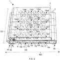
FIG. 2 is a top-down perspective view of an exemplary steam box in accordance with this disclosure. -
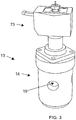
FIG. 3 is a view of a valve used with the exemplary steam box and exemplary system. -
FIG. 4 is a top-down perspective view showing removable diffuser plates from the diffuser chambers. -
FIG. 5 is a bottom-up perspective view showing the removable diffuser plates. -
FIG. 6 depicts further cross-sectional view of the exemplary steam boxes and systems described herein. -
FIG. 7 is a close-up bottom-up perspective view of a portion of an exemplary steam box detailing the removeable diffuser plates. -
FIG. 8 is a cross-sectional side view of a conventional steam box. -
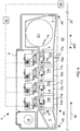
FIG. 9 is a schematic representation of an exemplary steam box system comprising a steam capacity control system. - The following detailed description of the preferred embodiments is presented only for illustrative and descriptive purposes and is not intended to be exhaustive or to limit the scope of the invention as defined by the claims. The embodiments were selected and described to best explain the principles of the invention and its practical application. One of ordinary skill in the art will recognize that many variations can be made to the invention disclosed in this specification without departing from the scope of the invention.
- Similar reference characters indicate corresponding parts throughout the several views unless otherwise stated. Although the drawings represent embodiments of various features and components according to the present disclosure, the drawings are not necessarily to scale and certain features may be exaggerated in order to better illustrate embodiments of the present disclosure, and such exemplifications are not to be construed as limiting the scope of the present disclosure.
- Except as otherwise expressly stated herein, the following rules of interpretation apply to this specification: (a) all words used herein shall be construed to be of such gender or number (singular or plural) as to circumstances require; (b) the singular terms "a," "an," and "the," as used in the specification and the appended claims include plural references unless the context clearly dictates otherwise; (c) the antecedent term "about" applied to a recited range or value denotes an approximation within the deviation in the range or values known or expected in the art from the measurements; (d) the words "herein," "hereby," "hereto," "hereinbefore," and "hereinafter," and words of similar import, refer to this specification in its entirety and not to any particular paragraph, claim, or other subdivision, unless otherwise specified; (e) descriptive headings are for convenience only and shall not control or affect the meaning or construction of any part of the specification; and (f) "or" and "any" are not exclusive and "include" and "including" are not limiting. Further, the terms, "comprising," "having," "including," and "containing" are to be construed as open-ended terms (i.e., meaning "including but not limited to").
- References in the specification to "one embodiment," "an embodiment," "an exemplary embodiment," etc., indicate that the embodiment described may include a feature, structure, or characteristic, but every embodiment may not necessarily include the feature, structure, or characteristic. Moreover, such phrases are not necessarily referring to the same embodiment. Further, when a particular feature, structure, or characteristic is described in connection with an embodiment, it is submitted that it is within the knowledge of one skilled in the art to affect such feature, structure, or characteristic in connection with other embodiments whether or not explicitly described.
- To the extent necessary to provide descriptive support, the subject matter and/or text of the appended claims is incorporated herein by reference in their entirety.
- Recitation of ranges of values herein are merely intended to serve as a shorthand method of referring individually to each separate value falling within the range of within any sub ranges there between, unless otherwise clearly indicated herein. Each separate value within a recited range is incorporated into the specification or claims as if each separate value were individually recited herein. Where a specific range of values is provided, it is understood that each intervening value, to the tenth or less of the unit of the lower limit between the upper and lower limit of that range and any other stated or intervening value in that stated range or sub range hereof, is included herein unless the context clearly dictates otherwise. All subranges are also included. The upper and lower limits of these smaller ranges are also included therein, subject to any specifically and expressly excluded limit in the stated range.
- It should be noted that some of the terms used herein are relative terms. For example, the terms "upper" and "lower" are relative to each other in location, i.e. an upper component is located at a higher elevation than a lower component in a given orientation, but these terms can change if the device is flipped. The terms "inlet' and "outlet" are relative to a fluid flowing through them with respect to a given structure, e.g. a fluid flows through the inlet into the structure and flows through the outlet out of the structure. The terms "upstream" and "downstream" are relative to the direction in which a fluid flows through various components, i.e. the flow of fluids through an upstream component prior to flowing through the downstream component.
- The terms "horizontal" and "vertical" are used to indicate direction relative to an absolute reference, i.e. ground level. However, these terms should not be construed to require structure to be absolutely parallel or absolutely perpendicular to each other. For example, a first vertical structure and a second vertical structure are not necessarily parallel to each other. The terms "top" and "bottom" or "base" are used to refer to locations/surfaces where the top is always higher than the bottom/base relative to an absolute reference, i.e. the surface of the Earth. The terms "upwards" and "downwards" are also relative to an absolute reference; an upwards flow is always against the gravity of the Earth.
-
FIG. 8 is a cross-sectional side view of aconventional steam box 50. Thesteam box 50 has ahousing 47, asteam inlet 63 disposed in a wall of thehousing 47, and asingle diffuser chamber 74 enclosed within thehousing 47. In operation,steam 7a from a steam source flows into asteam header 68 from thesteam inlet 63. Thesteam 7a then flows into one ormore valve conduits 79. Eachvalve conduit 79 connects to avalve 80 and thereby fluidly communicates with thevalve 80.Multiple valves 80 can extend along the width of thesteam box 50 in the cross-machine direction ("CD," seeFIG. 2 ). In different operational states, the depicted valves have a fully open position, a partially open position, and a fully closed position. If thevalve 80 is fully open, allsteam 7b traversing thevalve 80 exits thevalve 80 into thesingle diffuser chamber 74. The steam pressure in thesteam header 68 is regulated by a pressure control valve (see 77,FIG. 9 ) disposed in the steam supply line (see 76,FIG. 9 ) upstream of thesteam box 50. Thepressure control valve 77 regulates the amount ofsteam flow 7a entering thesteam box 50. Ifsteam 7a is entering thesteam box 50, thevalve 80 regulates amount ofsteam 7c exiting thesteam box 50. The steam supply system (78,FIG. 9 ) regulates the pressure in thesteam header 68, the steam's temperature, provides over-pressure safety relief, and removes condensate from the steam entering the steam box 50 (seeFIG. 9 ). - The portion of the
steam 7b that flows into thediffuser chamber 74 accumulates in thediffuser chamber 74 before exiting anexhaust side 89 of thesteam box 50 throughsteam exhaust orifices 67. Thesteam 7c that exits through theexhaust orifices 67 may contact the movingweb 20 disposed below the steam box. A layer ofair 53 is disposed between theexhaust side 89 of thesteam box 50 and theweb 20. - A portion of the
steam 7a diffuses into anouter steam header 66 from thesteam header 68. Thissteam 7d then exits thesteam box 50 near theupstream end 45 and thedownstream end 46 of thesteam box 50 at an angle to seal in thesteam 7c that exits thesteam box 50 through theexhaust orifices 67. Thisangled steam jet 7d effectively traps thesteam 7c between theexhaust side 89 of thesteam box 50 and the movingweb 20. This allows for appreciable "dwell time" of thesteam 7c between theexhaust side 89 and theweb 20, which permitsmore steam 7c to diffuse into theweb 20. However, the presence of theouter steam header 66 for theangled exhaust orifices 95 through which theangled steam 7d flows adds extra material to thesteam box 50, thereby making thesteam box 50 bulky, which can contribute to positioning restrictions within a paper or tissue making machine. Theangled steam jet 7d is also a further source of steam expenditure. - The
web 20 moves in direction M. A sensor (see 65,FIG. 6 ) can be disposed downstream of thesteam box 50. Thesensor 65 measures the moisture content of theweb 20 and relays the measurement information to a controller (see 69,FIG. 6 ). Thesensor 65 provides a CD moisture profile of theweb 20. If there are CD variations in the web's moisture profile (e.g. if portions of the web are too wet or too dry), operators or algorithms can open, close, and partiallyopen valves 80 arrayed along the CD in thesteam box 50 to attempt to equalize the moisture profile. - However,
steam boxes 50 like thesteam boxes 50 depicted inFIG. 8 , are designed to havesteam 7c exit theseexhaust orifices 67 consistently at 100% of the design-rated exit flow capacity. For example, if the steam box is rated to introducesteam 7c into the web at a rate of 200 kilograms ("kg") per ton ("T") of paper (or tissue) produced, ideal production assumptions can only be met if the steam is exiting the steam box at a rate of 200 kg/T of paper (or tissue) produced. - When an operator or algorithm partially closes a valve 80 (such that the
valve 80 is in a partially open position) to attempt to equalize the web's moisture profile in response to sensor readings, the operator or algorithm not only reduces the amount of exitingsteam 7c (expressed as a percentage of the design-rated exit flow), but the operator or algorithm also increases the time required for the remainingsteam 7b entering thesingle diffuser box 74 to reach thesteam exhaust orifices 67. Furthermore, when an operator or algorithm partially closes avalve 80, the operator or algorithm also increases the time required for thesteam 7c exiting thesteam exhaust orifices 67 to travel to the movingweb 20. As such, thesteam 7c exits theexhaust side 89 of thesteam box 50 not only at an amount that is below the design-rated capacity (the design-rated capacity capable as being expressed in kg/T of paper produced), but thesteam 7c also exits theexhaust side 89 of thesteam box 50 at a lower speed. As a result, the paper or tissue producer expends more energy to produce less paper or tissue product. - The design of the
steam box 50 inFIG. 8 also can also lead to other problems. For example, if the speed, and therefore the impulse of thesteam 7c exiting thesteam box 50 is too low, thesteam 7c will not penetrate the layer orair 53 disposed between theexhaust side 89 of thesteam box 50 and theweb 20. When this happens, thesteam box 50 is not effectively drying theweb 20 and the energy is wasted. Lower steam exit speeds also allowsteam 7c to diffuse more in the layer ofair 53 before reaching theweb 20. As a result, an operator's ability to target a desired section of theweb 20 degrades as steam exit speed decreases. - Conversely, if the impulse of the
steam 7c is too high, the steam will destroy the surface of theweb 20. This can render this surface unsuitable for receiving coatings downstream, which can eventually render the paper unsuitable for printing. If the steam impulse is too great, the steam can also accumulate in areas of higher pressure over theweb 20, thereby re-directing incoming steam to untargeted areas of the web, and causing some of thesteam 7c to flow back toward theexhaust side 89 of thesteam box 50 without interacting with theweb 20. This steam blowback also increases energy consumption and waste. - The Applicant has discovered that the steam output of conventional steam boxes drops off in a non-linear manner. To address the problems of
conventional steam boxes 50, Applicant details several exemplary embodiments in accordance with the present disclosure. -
FIG. 1 is a cross-sectional view of an exemplary embodiment of asteam box 1 in accordance with the present disclosure. Thesteam box 1 comprises asteam box housing 3 and asteam header 5 disposed within thesteam box housing 3.Steam 7a from the steam inlet (21 inFIG. 6 ) collects in thesteam header 5. Thesteam box 1 further comprises adiffuser housing 9 disposed within thesteam header 5. Thediffuser housing 9 hasmultiple walls 8 that extend from the top of thediffuser housing 9. Themultiple walls 8 divide an inside 10 of thediffuser housing 9 into multiple diffuser chambers see 10a, 10b, 10c, 10d arranged adjacently in the machine direction ("MD"), and thereby define multiple diffuser chambers. The multiple diffuser chambers comprise at least afirst diffuser chamber 10a and asecond diffuser chamber 10b. Thefirst diffuser chamber 10a is adjacently disposed to thesecond diffuser chamber 10b in the MD Thesteam box 1 is disposed above a fibrous web 20 (e.g. which later dries through further processing into a sheet of paper, tissue, or other non-woven sheet of fibrous material depending upon the production equipment and feed stock). - Each
diffuser chamber steam box housing 3 may define ends (not depicted in the cross-sectional view) of thediffuser chambers steam box 1 distal from thetop 6 of thediffuser housing 9 and adjacent to themultiple diffuser chambers exhaust side 89 of thesteam box 1. Thediffuser chambers diffuser plate 15 and therefore theexhaust side 89 of thesteam box 1. Thediffuser plate 15 can further define any of thediffuser chambers diffuser plate 15 can be asingle diffuser plate 15 havingorifices 17 that define multiple steam exhaust orifice areas OAs (FIG. 5 ). In such embodiments, a first steam exhaust orifice area OA1 is disposed at theexhaust side 89 adjacent to thefirst diffuser chamber 10a. A second steam exhaust orifice area OA2 is disposed at theexhaust side 89 adjacent to thesecond diffuser chamber 10b. In such embodiments that comprise more than two diffuser chambers, a steam exhaust orifice area OAz is disposed at theexhaust side 89 adjacent to the z diffuser chamber, where "z" is the number of the diffuser chamber. In other exemplary embodiments, adiffuser plate 15 can be disposed under two ormore diffuser chambers different diffuser plate different diffuser chamber first diffuser plate 15a is disposed under afirst diffuser chamber 10a, asecond diffuser plate 15b is disposed under asecond diffuser chamber 10b, etc. -
Multiple valves 13 can be disposed on thetop 6 of thediffuser housing 9 such that eachvalve 13 fluidly communicates with at least one of thediffuser chambers FIG. 2 , 13a1, 13a2, 13a3, 13a4, 13b1, 13b2, 13b3, 13b4, 13c1, 13c2, 13c3, 13c4, 13d1, 13d2, 13d3, 13d4) of themultiple valves 13 has a valve outlet 22. For the purposes of this disclosure, a particular valve (e.g. 13a1) or set of valves (e.g. 13a) disposed over a particular diffuser chamber (e.g. 10a) can be referred to as a valve (e.g. 13a1) or set of valves (e.g. 13a) of saiddiffuser chamber 10a. Thediffuser plate 15 has one or moresteam exhaust orifices 17 through which thesteam 7c may flow when thevalves 13 are in an open position. Unlike in prior steam boxes, thevalves 13 of the present disclosure are configured to be either fully open (i.e. 100% open; the "open position") or fully closed, (i.e. 0% open; the "closed position"). When a valve is in the fully open position,steam 7b flows into the diffuser chamber (e.g. 10a, 10b, 10c, 10d) over which thevalve 13 is disposed. - In certain exemplary embodiments, the
valve 13 may be a solenoid valve (seeFIG. 3 ). When the valve is in an open position,steam 7a flows from thesteam header 5 through avalve orifice 19 and out of the valve outlet 22 into one of themultiple diffuser chambers valve 13 can be said to "fluidly communicate" with a diffuser chamber. It is contemplated that in certain exemplary embodiments, the size of thevalve orifice 19 may vary to optimize the flow ofsteam 7a from thesteam header 5 into aspecific diffuser chamber - In certain exemplary embodiments, there are
multiple diffuser plates 15. In these embodiments, eachdiffuser plate diffuser chamber top 6 of thediffuser housing 9, thewalls 8 of thediffuser housing 9, and afirst diffuser plate 15a of the plurality ofdiffuser plates 15 define afirst diffuser chamber 10a in thediffuser housing 9. Thetop 6 of thediffuser housing 9, thewalls 8 of thediffuser housing 9, and asecond diffuser plate 15b of the plurality ofdiffuser plates 15 define asecond diffuser chamber 10b in thediffuser housing 9. Thetop 6 of thediffuser housing 9, thewalls 8 of thediffuser housing 9, and athird diffuser plate 15c of the plurality ofdiffuser plates 15 define athird diffuser chamber 10c in thediffuser housing 9. Thetop 6 of thediffuser housing 9, thewalls 8 of thediffuser housing 9, and afourth diffuser plate 15d of the plurality ofdiffuser plates 15 define afourth diffuser chamber 10d in thediffuser housing 9. In embodiments comprising five diffuser chambers (not depicted), thetop 6 of thediffuser housing 9, thewalls 8 of thediffuser housing 9, and a fifth diffuser plate of the plurality of diffuser plates can define a fifth diffuser chamber in thediffuser housing 9. In embodiments comprising more than five diffuser chambers, thetop 6 of thediffuser housing 9, thewalls 8 of thediffuser housing 9, and a "y-th" diffuser plate of the plurality of diffuser plates can define a "y-th" diffuser chamber in thediffuser housing 9, wherein "y" is the number of the indicated diffuser chamber. - A
first valve outlet 22a of at least a first valve 13a1 of themultiple valves 13 is disposed in thefirst diffuser chamber 10a.Steam 7a can pass from thesteam header 5 through the valve (e.g. 13a1) when the valve (e.g. 13a1) is in the open position. In this manner, each of thevalves 13 can be configured to fluidly communicate with the valve'srespective diffuser chamber second valve 13b fluidly communicates with thesecond diffuser chamber 10b. Likewise, at least athird valve 13c fluidly communicates with thethird diffuser chamber 10c and at least afourth valve 13d fluidly communicates with thefourth diffuser chamber 10d. In embodiments comprising five diffuser chambers, at least a fifth valve can fluidly communicate with the fifth diffuser chamber. In embodiments comprising more than five diffuser chambers, a "y-th" valve fluidly communicates with the "y-th" diffuser chamber, wherein "y" is the number of the indicated diffuser chamber. - The number of
steam exhaust orifices 17 perdiffuser plate 15 varies depending upon the desired capacity ofsteam 7c exiting a givendiffuser chamber FIG. 5 , thefirst diffuser plate 15a defines a first steam exhaust orifice area OA1 (represented schematically and not to scale by the area inside the rectangle OA1). The first steam exhaust orifice area OA1 has a first value. In the depicted exemplary embodiment, thefirst diffuser plate 15a defines the first steam exhaust orifice area OA1 with a single linearsteam exhaust orifice 17. It will be understood that in other exemplary embodiments, the steam exhaust orifice(s) 17 may assume a variety of shapes. For example, the steam exhaust orifice(s) 17 may be a plurality of holes. Thesteam exhaust orifices 17 may be arranged in any pattern, or lack thereof in thediffuser plate 15. The "steam exhaust orifice area" represents the total area occupied by steam exhaust orifice(s) 17 for the steam exhaust orifice(s) 17 disposed under a givendiffuser chamber steam 7c does not exit theexhaust side 89 substantially perpendicular to the section of theweb 20 disposed adjacent to theexhaust side 89 of thesteam box 1. -
Steam 7b that collects in thefirst diffuser chamber 10a moves from an area of higher pressure to an area of lower pressure and thereby exits thefirst diffuser chamber 10a through the first steam exhaust orifice area OA1. In this manner, thediffuser chambers diffuser plates steam 7c into the movingweb 20. The value of the first steam exhaust orifice area OA1 can be represented by "v." - The
second diffuser plate 15b defines a second steam exhaust orifice area OA2 (FIG. 5 ). The second steam exhaust orifice area OA2 has a second value. The second value is equal to an exponentiation vn, wherein "v" is the first value, and "n" is a real number excluding 0. - For example, in
FIG. 1 andFIG. 5 , vn is a power of 2. The first value of the first steam exhaust orifice area OA1 is v0 where v = 2. Stated differently, 20 = 1. The second value of the second steam exhaust orifice area OA2 is v1 where v = 2. Stated differently, 21 = 2. The third value of the third steam exhaust orifice area OA3 is v2 where v = 2. Stated differently, 22 = 4. The fourth value of the fourth steam exhaust orifice area OA4 is v3 where v = 2. Stated differently, 23 = 8. - Although
FIG. 1 andFIG. 5 depictdiffuser plates steam exhaust orifices 17 decreasing from 8, to 4, to 2, to 1 as theweb 20 moves from theupstream end 45 to thedownstream end 46, it will be understood that in other exemplary embodiments, operators may re-position the diffuser plates (see 15d, 15c, 15b, 15a) to accommodate the properties of aparticular paper web 20. For example, an exemplary embodiment may havediffusers plates 15 having steam exhaust orifice areas OAs arranged respectively from 4, to 8, to 1, to 2 from theupstream end 45 to thedownstream end 46. Still other exemplary embodiments may arrange thediffuser plates 15 having steam exhaust orifice areas OAs arranged respectively from 4, to 4, to 4, to 2. In other exemplary embodiments, the values of the steam exhaust orifice areas OAs are equal to the exponentiation vn, but the exponentiation vn is a power of 3. In yet other exemplary embodiments, the exponentiation vn can have values other that powers of 2 and powers of 3. Combinations and permutations of any of the described embodiments or examples are within the scope of this disclosure. - Without being bound by theory, Applicant believes that exemplary embodiments in accordance with the present disclosure separate the properties of steam capacity (also known as the amount of available steam to be introduced into the web 20) and steam speed.
Steam boxes 1 in accordance with the present disclosure permit controlled variation of the amount of available steam available to be ejected from thesteam exhaust orifices 17 without varying the speed at which steam 7c is ejected fromactive diffuser chambers 10. - It is envisioned that steam exiting a
steam box 1 in accordance with the present disclosure can constantly penetrate theweb 20 at a desirably constant speed and thereby give proper zone definition without steam spilling into other zones. For example, in certain exemplary embodiments wherein theweb 20 is a paper web, anexemplary steam box 1 can be configured to expel steam fromactive diffuser chambers 10 at a rate of 27 meters per second ("m/s"). In exemplary embodiments wherein theweb 20 is a tissue web, anexemplary steam box 1 can be configured to expel steam fromactive diffuser chambers 10 at a rate of 1.4 times the web speed. For example, if the web moves by thesteam box 1 at a rate of between 1,000 to 1,800 meters per minute ("m/min."), thesteam box 1 can expelsteam 7c at a rate of between 23⅓ m/s - 42 m/s. - Referring to the embodiment depicted in
FIG. 1 , the capacity of the depicteddiffuser chambers valves 13 are in the open position is 100% of the design-rated steam output capacity. If readings from the CDmoisture profile sensor 65 indicate that theweb 20 is dryer than expected, operators or algorithms can close all the valves disposed over a certain diffuser chamber to reduce theavailable steam 7c and thereby avoid waste. - For example, if the CD
moisture profile sensor 65 indicates that more than 40% to 462/3% of the maximum steam capacity is sufficient to dry a particular section of theweb 20, operators or algorithms can open thevalves 13 disposed over thefirst diffuser chamber 10a, thesecond diffuser chamber 10b, and thethird diffuser chamber 10c while closing the valves disposed over thefourth diffuser chamber 10d. Thevalves 13 over theactive diffuser chambers steam 7c exits theexhaust orifices 17 of the first, second, andthird diffuser chambers steam 7c exiting theactive diffuser chambers web 20 over a given time. The speed at which thesteam 7c exits theactive diffuser chambers web 20 and to be fully absorbed by the web 20 (i.e. to condense in theweb 20 nearly completely). By maintaining the speed at which thesteam 7c is introduced into theweb 20, it is contemplated that the steam can maintain a nearly constant impulse sufficient to penetrate the laminate layer orair 53 disposed between theexhaust side 89 and theweb 20, while giving operators greater control over increasing or decreasing the web temperature at more precise positions than was previously thought possible. The different capacities of steam leaving different active diffuser chambers (e.g. 10a and 10b) have the same impulse, and thereby separate the properties of steam capacity from steam speed. - The
steam 7c condensing in theweb 20 raises the temperature of water entrapped in the web, thereby lowering the water's viscosity and facilitating of the removal of the liquid, which now includes the condensedsteam 7c, via a vacuum source in the press section. For this reason, the temperature of the steam can desirably be just above the boiling temperature of water adjusted for pressure. Stated simply, the lower the viscosity of the liquid in theweb 20, the more liquid the vacuum source in the press section can remove. In this manner, the embodiments in accordance with the present disclosure allow the reduction of available steam capacity without altering the speed at which the remainingsteam 7c exits theexhaust orifices 17. - The steam capacity of given
diffuser chamber diffuser plates FIG. 1 ) the greater capacity that diffuserchamber steam - In the depicted embodiment, the
first diffuser plate 15a has the smallest first steam exhaust orifice area OA. When the first set ofvalves 15a are fully open,steam 7c exits thefirst diffuser chamber 10a through thefirst diffuser plate 15a at a rate of 1x, where "x" is the first diffuser chamber's steam capacity. Steam capacity can be expressed in kilograms per hour ("kg/hr") or as a percentage of the steam box's total steam capacity. - The
second diffuser plate 15b hasorifices 17 configured to expel steam at a steam capacity rate of 2x. Thethird diffuser plate 15c hasorifices 17 configured to expel steam at a steam capacity rate of 4x. Thefourth diffuser plate 15d hasorifices 17 configured to expel steam at a steam capacity rate of 8x. Other exemplary embodiments can have more than four diffuser chambers. Still other exemplary embodiments can have two diffuser chambers. Yet other exemplary embodiments can have three diffuser chambers. - It will be appreciated that in any of the
diffuser plates steam exhaust orifices 17. The multiplesteam exhaust orifices 17 may be arranged in any manner provided that the collectivemultiple orifices 17 of eachdiffuser plate diffuser chamber FIG. 5 depictsmultiple orifices 17 for each diffuser plates disposed in a line or in a series of lines. - A steam box controller (69,
FIG. 6 andFIG. 9 ) signally communicates with each of thevalves 13. Thesteam box controller 69 sets the valves into the open position or the closed position. It is contemplated that the exemplary embodiments will permit a constant steam speed while allowing operators to vary the amount of available steam (i.e. steam capacity) based on need. For example, with fourdiffuser chambers valves 13 associated with each of the fourdiffuser chambers first diffuser plate 15a can have anorifice 17 designed to permitsteam 7c to exit thefirst diffuser plate 15a toward theweb 20 at a steam capacity of 1x, where "x" is the first diffuser chamber's steam capacity. Asecond diffuser plate 15b can then be designed to have an exit steam capacity of 2x. Athird diffuser plate 15c can be designed to have an exit steam capacity of 4x. Afourth diffuser plate 15d can be designed to have an exit steam capacity of 8x. Thesteam box controller 69 can be programed to count in a base two system to selectively open and close thevalves steam box controller 69 can effectively count in binary to selectively open andclose valves 13 to allowsteam 7 to flow out of at least onediffuser orifice 17 are a rate between 0% and 100%. - With exemplary embodiments comprising four diffuser chambers, 10a, 10b, 10c, 10d, the operator can control the amount of
steam 7c ejected into theweb 20 as a percentage of the steam box's total steam capacity (i.e. 100%) while ensuring that the amount of steam ejected toward the movingweb 20 is ejected at a constant speed, thereby ensuring good penetration and good zone definition. Good zone definition (e.g. both CD zone and MD zone definition) prevents steam from diffusing into adjacent zones that may not need additional drying. - For example, in an
exemplary steam box 1 having four diffuser chambers, 10a, 10b, 10c, 10d, "x" is 6

first diffuser chamber 10a when the set of valves 13a disposed above thefirst diffuser chamber 10a are in the open position. Stated yet another way,
steam 7c into the web at a rate of
first diffuser chamber 10a. In embodiments wherein thesteam box 1 comprises four diffuser chambers, opening only the set of valves 13a disposed above thefirst diffuser chamber 10a is referred to as "Step 1". In the depicted embodiment, a total of sixteen steps (i.e. fifteen steps plus a step 0) are available to permit the exemplary system to change the operating steam capacity (expressed as a percentage of the steam box's maximum design-rated steam capacity) depending upon web moisture profile variations while ensuring that the speed of steam output for any of the selected total amount of steam output remains constant. The below table details the sixteen steps, each step's actual steam output (i.e. the steam box's operating steam capacity associated with each step, expressed as a percentage of the steam box's maximum design-rated steam capacity), and the corresponding diffuser chambers that havevalves 13 in the open position. It will be understood that "active diffuser chamber" means a diffuser chamber for which thevalves 13 disposed over said diffuser chamber are in the open position.Table 1 Steam Capacity Target Range from the CD Control Software [%] Step Number Step Number in Binary Active Diffuser Chambers Actual Steam Capacity Output [%] 0 - 3⅓ 0 0 none 0 > 3⅓ - 10 1 1 10a 

2 10 10b 13⅓ 
3 11 10b, 10a 20 > 23⅓ - 30 4 100 10c 

5 101 10c, 10a 33⅓ 
6 110 10c, 10b 40 > 43⅓ - 50 7 111 10c, 10b, 10a 

8 1000 10d 53⅓ 
9 1001 10d, 10a 60 > 63⅓ - 70 10 1010 10d, 10b 

11 1011 10d, 10b, 10a 73⅓ 
12 1100 10d, 10c 80 > 83⅓ - 90 13 1101 10d, 10c, 10a 

14 1110 10d, 10c, 10b 93⅓ 
15 1111 10d, 10c, 10b, 10a 100 - Other
exemplary steam boxes 1 can have five or more diffuser chambers. In asteam box 1 having five diffuser chambers for example, the resolution of the change in available steam flow output is 3.22580645%. It will be understood that "active diffuser chamber" means a diffuser chamber for which the valves disposed over said diffuser chamber are in the open position. The first diffuser chamber (see 10a), second diffuser chamber (see 10b), third diffuser chamber (see 10c), fourth diffuser chamber (see 10d), and fifth diffuser chamber are abbreviated 1, 2, 3, 4, and 5 respectively in the below Table 2. The resolution of 3.22580645% has been rounded to three significant figures in the below table.Table 2 Steam Capacity Target Range from the CD Control Software [%] Step Number Step Number in Binary Active Diffuser Chambers Actual Steam Capacity Output [%] 0 - 1.6 0 0 none 0 > 1.6 - 4.83 1 1 1 3.23 > 4.83 - 8.06 2 10 2 6.46 > 8.06 - 11.29 3 11 2, 1 9.69 > 11.29 - 14.52 4 100 3 12.92 > 14.52 - 17.75 5 101 3, 1 16.15 > 17.75 - 20.98 6 110 3, 2 19.38 > 20.98 - 24.21 7 111 3,2,1 22.61 > 24.21 - 27.44 8 1000 4 25.84 > 27.44 - 30.67 9 1001 4, 1 29.07 > 30.67 - 33.90 10 1010 4, 2 32.3 > 33.90 - 37.13 11 1011 4, 2, 1 35.53 > 37.13 - 40.36 12 1100 4, 3 38.76 > 40.36 - 43.59 13 1101 4,3,1 41.99 > 43.59 - 46.82 14 1110 4,3,2 45.22 > 46.82 - 50.05 15 1111 4, 3, 2, 1 48.45 > 50.05 - 53.28 16 10000 5 51.68 > 53.28 - 56.51 17 10001 5, 1 54.91 > 56.51 - 59.74 18 10010 5, 2 58.14 > 59.74 - 62.97 19 10011 5, 2, 1 61.37 > 62.97 - 66.20 20 10100 5, 3 64.60 > 66.20 - 69.43 21 10101 5, 3, 1 67.83 > 69.43 - 72.66 22 10110 5, 3, 2 71.06 > 72.66 - 75.89 23 10111 5, 3, 2, 1 74.29 > 75.89 - 79.12 24 11000 5, 4 77.52 > 79.12 - 82.35 25 11001 5, 4, 1 80.75 > 82.35 - 85.58 26 11010 5, 4, 2 83.98 > 85.58 - 88.81 27 11011 5, 4, 2, 1 87.21 > 88.81 - 92.04 28 11100 5, 4, 3 90.44 > 92.04 - 95.27 29 11101 5, 4, 3, 1 93.67 > 95.27 - 98.50 30 11110 5, 4, 3, 2 96.90 > 98.50 - 100 31 11111 5, 4, 3, 2, 1 100 -
FIG. 2 is a top-down perspective view of anexemplary steam box 1.FIG. 2 further details themultiple valves 13 fluidly communicating with thediffuser chambers first diffuser chamber 10a are designated with the reference character prefix 13a. Likewise, the set of valves fluidly communicating with thesecond diffuser chamber 10b are designated with thereference character prefix 13b and the set of valves fluidly communicating with thethird diffuser chamber 10c are designated with thereference character prefix 10c. Finally, the set of valves configured to fluidly communicate with thefourth diffuser chamber 10d are designated with thereference character prefix 13d. - The
diffuser chambers steam box 1 in the CD. Adjacent diffuser chambers (e.g. 10a and 10b) are arranged in the MD. The area under a diffuser chamber (e.g. 10a) defines a MD zone. Each MD zone extends lengthwise in the CD. Themultiple valves 13 are further classified by CD zone (e.g. 1, 2, 3, 4 inFIG. 2 ). Each CD zone extends lengthwise in the MD. Adjacent CD zones (e.g. 1 and 2) are arranged in the CD. For reference, the last number for a valve character reference indicates the CD zone of that valve (e.g. 13c3 is inCD zone 3 and MD zone c). - Referring to
FIG. 6 , in operation,steam 7a enters thehousing 3 of thesteam box 1 through thesteam inlet 21. Thesteam 7a collects in thesteam header 5. If any of the valves in a set ofvalves steam 7a will flow through the open valve (e.g. 13a1 inFIG. 6 ) and into the associated diffuser chamber (e.g. thefirst diffuser chamber 10a inFIG. 6 ). Thesteam 7b then collects in the associated diffuser chamber (e.g.first diffuser chamber 10a) before exiting the associated diffuser chamber through theorifices 17 in the associated diffuser plate (e.g. thefirst diffuser plate 15a inFIG. 6 ). Thesteam 7c desirably exits at a speed sufficient to penetrate the laminate layer ofair 53 disposed between theexhaust side 89 of thesteam box 1. Thesteam 7c may further exit thesteam box 1 at a speed at which thesteam 7c can fully condense into the movingweb 20. Fully condensed steam will heat the water entrapped in theweb 20 evenly, lower the water's viscosity, and permit the vacuum source to remove more water in a given time interval than would be possible if thesteam 7c were not fully condensed in theweb 20. -
Conduit 33 permits cables from thesteam box controller 69 to connect to the valve actuators (seesolenoid component 73,FIG. 3 ). - A
sensor 65 can be disposed downstream of thedownstream end 46 of thesteam box 1. Thesensor 65 can be a CD moisture sensor configured to measure the CD moisture profile of the web. Thesensor 65 signally communicates with acontroller 69. That is, thesensor 65 can convey the measurement to thecontroller 69 via a signal through an electrical conduit (e.g. a conductive wire) or wirelessly. - The CD moisture profile generally represents the CD moisture profile of the
web 20 at a given time. The CD moisture profile typically indicates the moisture of theweb 20 at CD zones that correspond to the CD zones (e.g. 1, 2, 3, 4 inFIG. 2 ) of thesteam box 1. Thecontroller 69 will evaluate the signal from thesensor 65 and adjust the open or closed position of thevalves 13 to equalize the CD moisture profile. - For example, if the moisture profile of CD zone 2 is wetter than
CD zones controller 69 will open one or more valves in CD zone 2 (e.g. one of more of 13a2, 13b2, 13c2, 13d2 inFIG. 2 ) to equalize the moisture profile and thereby promote even and consistent drying of theweb 20. - By way of a further example, if a particular CD moisture profile indicated that the aggregate steam output of
CD zone 1 should be 20% of the total possible output ofCD zone 1, CD zone 2's aggregate steam output should be 80% of CD zone 2's total possible output,CD zone 3 should be 50% ofCD zone 3's total possible output, and CD zone 4 should be 60% of CD zone 4's total possible output, the followingvalves 13 would be open: - CD zone 1: 13a1 and 13b1 = 20% of actual steam output for
CD zone 1; - CD zone 2: 13c2 and 13d2; = 80% of actual steam output for CD zone 2;
- CD zone 3: 13d3 = 53⅓% of actual steam output for
CD zone 3; - CD zone 4: 134, 13a4 = 60% of actual steam output for CD zone 4.
-
FIG. 3 is a detailed view of avalve 13 than can be used with thesteam box assembly 1. The valve may be a solenoid steam valve comprising asteam valve component 14 and asolenoid component 73. -
FIG 4 is a perspective view of anexemplary steam box 1.FIG. 4 highlights an embodiment in which thediffuser plates 15 are removable.FIG. 4 depicts thefourth diffuser plate 15a being slid out from under thefourth diffuser chamber 10a. It is contemplated that having multipleremovable diffuser plates 15 may allow servicers to repair and replace worn plates while minimizing downtime. Further,removable diffuser plates 15 may allow operators to change the pattern oforifices 17 on eachdiffuser plate 15 to adjust for different physical characteristics of a web 20 (FIG. 1 ) or to accommodate changing characteristics for a runningweb 20.FIG. 4 also depicts asteam inlet conduit 21. Thisinlet conduit 21 conveyssteam 7 from a steam source into thesteam header 5. -
FIG. 7 depicts further views of an exemplary steam box embodiment. It is contemplated that the use ofmultiple valves 13,multiple diffuser chambers multiple diffuser plates 15 can allow designers to make theoverall steam box 1 more compact than conventional designs. The depicted embodiment lacks theouter steam header 66 and theangled exhaust orifices 95 shown in theconvention steam box 50 inFIG. 8 , thereby permitting exemplary embodiments to be smaller than conventional designs like those depicted inFIG. 8 . Exemplary embodiments can forgo theouter steam header 66 and theangled exhaust orifices 95 because the exemplary embodiments can preserve optimal steam speed to optimal steam absorption into theweb 20. Furthermore, preserving a constant rate of steam speed with the exemplary embodiments permits less steam "dwell time" between theexhaust side 89 and theweb 20 compared to the conventional design disclosed inFIG. 8 . The reduced dwell time permitsexemplary steam boxes 1 to be shorter in the MD compared to designs that useouter steam headers 66 andangled exhaust orifices 95. -
FIG. 7 further details a key 23 and lock 27 assembly that can be used to remove theremovable diffuser plates 15. In the depicted embodiment, thediffuser plates 15 have abackside 16 extending through thesteam box housing 3. Thebackside 16 has alock assembly 17 configured to receive a key 23. The key 23 may be a ring, handle, lever, or other device configured to unlock theremovable diffuser plate 15 and preferably to facilitate the removal ofsuch diffuser plate 15. The diffuser plate may slide alongrails 25 as thediffuser plate 15 exits thesteam box housing 3. It will be understood that any way of removably securing thediffuser plate 15 to thesteam box 1 is considered to be within the scope of this disclosure. -
FIG. 9 is a schematic representation of an exemplary steam box system in accordance with the present disclosure. Theweb 20 moves in direction M under anexemplary steam box 1 and ameasurement platform 61 disposed downstream of thesteam box 1. One ormore sensors 65 are disposed in themeasurement platform 61. Thesensor 65 typically travels back and forth across the CD of theweb 20 and scans theweb 20 to create a high-resolution CD moisture profile every time thesensor 65 traverses theweb 20. Measurement intervals may vary, but thesensor 65 commonly traverses theweb 20 every 30 to 60 seconds. Thesensor 65 then transmits the high-resolution CD moisture profile toCD control software 62. Although theCD control software 62 is depicted as a separate object inFIG. 9 , it is understood that the CD control software may run in themeasurement platform 61, thesteam box controller 69, or on any other platform configured to run software. - The CD moisture profile is readable by the
CD control software 62. The CD control software then maps the high-resolution CD moisture profile into a CD control profile that matches the moisture content of the web 20 a steam box CD zone. For example, the high-resolution CD moisture profile typically comprises a series of arrays of sensor data. Arrays 1 - 10 for example may correspond to the area of theweb 20 affected byCD zone 1 of theexemplary steam box 1. Arrays 11 - 20 may correspond to CD zone 2, etc. TheCD control software 62 then calculates a steam capacity target (expressed in a percentage of the steam box's total available flow capacity (Table 1 and Table 2)) for steam flow from the CD zones after every scanner update. If the moisture of a given CD zone is less than the average for example, the steam box setpoint will be decreased. If the moisture of a given CD zone is higher than the average, the steam flow capacity will increase. - The
CD control software 62 generates an output. The output contains the setpoint data for thesteam box controller 69. The output is transmitted as a signal to thesteam box controller 69 to adjust the steam flow capacity. Thesteam box controller 69 rounds the steam capacity target to the closest binary number that will be used to control the valves 13 (Table 1 and Table 2). For example, with reference to the embodiment disclosed inFIG. 2 and to Table 1, if the CD control software sets the steam capacity target of CD zone 2 to 72% of CD zone 2's total steam output capacity, then thesteam box controller 69 will round 72% to the closest step in Table 1, which is step 11. The number "11" is expressed as "1011" in binary. The binary expression "1011," when transmitted programmatically as an electrical or pneumatic signal, to thesteam box 1, will open valves 13d2, 13b2, and 13a2 and close valve 13c2 to adjust the output capacity of CD zone 2 while maintaining a constant steam speed for thesteam 7c that exits theexhaust side 89 of thesteam box 1 in CD zone 2. The actual steam capacity output of CD zone 2 will be 73⅓% of CD zone 2's total output capacity. - Feedback and status signals from the
steam box controller 69 can be transmitted back to theCD control software 62. It will be appreciated that signals can be transmitted via wires (e.g. Ethernet, serial communication link, or other physical connectivity) or wirelessly. - Upon receipt of the setpoint data, the
steam box controller 69 converts the setpoints to electrical or pneumatic signals to control the open or closed position of thevalves 13 in each CD zone. The electrical or pneumatic signals may be transmitted to thesteam box 1 via one signal line per CD zone. In other exemplary embodiments, a single interface may be used withintelligent control valves 13. Thesteam box controller 69 can also transmit status or feedback signals to theCD control software 62 and an operator display. It will be appreciated that operator displays may be used to visualize any of the data utilized by this exemplary system. The displays may be secured proximate to system equipment, or the displays may be on portable devices. -
FIG. 9 further details asteam supply system 78. Thesteam supply system 78 comprises asteam supply controller 71 such as a DCS or a PLC. Thesteam supply controller 71 controls aflow indicator 72, atemperature controller 75, interlocks 81, and apressure controller 82. Theflow indicator 72 signally communicates with aflow sensor 83. "Signally communicates" means that a signal is transmitted from one point and is received by another via wires or wirelessly. InFIG. 9 , the signal communication is represented by the dotted lines between two points. Thetemperature controller 75 signally communicates with atemperature valve 84 and atemperature sensor 85. Theinterlocks 81 signally communicate with avent valve 86 and adrain valve 87. Thevent valve 86 anddrain valve 87 are typically used with the start-up and shut down of thesteam supply system 87. Thepressure controller 82 signally communicates with thepressure control valve 77 and apressure sensor 88. -
Steam 7 from thesteam source 90 travels through thesteam supply line 76 past theflow sensor 83. Theflow sensor 83 can measure the amount ofsteam 7 and the rate ofsteam 7 entering thesteam supply system 78.Steam 7 from thesteam source 90 may have a temperature of over 300 degrees Fahrenheit ("°F") and enter thesteam supply system 78 at a pressure of between about 70 pounds per inch ("ppi") to about 150 ppi.Exemplary steam boxes 1 can be rated to accommodate pressures of less than 15 ppi. - To reduce the pressure of the
incoming steam 7, thepressure controller 82 open and closes thepressure control valve 77 to limit the amount of steam available to thesteam box 1. Readings from thepressure sensor 88 indicate the adjustments that thepressure controller 82 should make. If the readings from thepressure sensor 88 ever indicate that the steam in thesteam supply line 76 surpasses the design-rated pressure of thesteam box 1, asafety valve 94 will open to vent theexcess steam 7. - It is desirable to reduce the temperature of the
steam 7 to be just above the boiling point of water for the steam's pressure. Being just above the boiling point permits thesteam 7c to condense into theweb 20 faster than hotter steam that is significantly above water's boiling point. Thetemperature sensor 85 measures the temperature of thesteam 7 in thesteam supply line 76 and transmits the steam's temperature at intervals to thetemperature controller 75. Thetemperature controller 75 in turn transmits signals to thetemperature valve 84, which regulates the amount of coolingwater 93 that is introduced into thesteam supply line 76. The coolingwater 93 thereby reduces the steam's temperature to desirable levels. The coolingwater 93 originates in acooling water source 91 and mixes with thesteam 7 in a desuperheater 92 disposed in thesteam supply line 76. - An exemplary steam box comprises: a diffuser housing disposed within the steam header, wherein walls disposed in the diffuser housing divide an inside of the diffuser housing into multiple diffuser chambers, wherein a valve is configured to fluidly and programmatically communicate with each of the multiple diffuser chambers, such that a steam from the header box selectively enters one of the diffuser chambers depending upon the valve's orientation in an open or closed position, and multiple orifices of different sizes per diffuser chamber.
- An exemplary steam box can further comprise a first diffuser plate having a steam exhaust orifice configured to permit an exit flow of steam at 1x, where "x" is the first diffuser chamber steam capacity. An exemplary steam box can further comprise a second diffuser plate configured to have an exit flow of steam at 2x, wherein "x" is the first diffuser chamber steam capacity. An exemplary steam box can further comprise a third diffuser plate configured to have an exit flow of steam at 4x, wherein "x" is the first diffuser chamber steam capacity. An exemplary steam box can further comprise fourth diffuser plate configured to have an exit flow of steam at 8x, wherein "x" is the first diffuser chamber steam capacity. In certain exemplary embodiments, the first diffuser chamber steam capacity is 1% to

- An exemplary steam box assembly can comprise: a steam box housing; a diffuser housing disposed within the steam box housing, wherein the diffuser housing comprises a top, and walls extending downwardly from the top; wherein the top of the diffuser housing and the walls of the diffuser housing define multiple diffuser chambers disposed adjacently in a machine direction, and wherein the multiple diffuser chambers further comprise a first diffuser chamber adjacently disposed to a second diffuser chamber; a diffuser plate engaged to the steam box housing distal from the top of the diffuser housing and adjacent to the multiple diffuser chambers to define an exhaust side, the diffuser plate having orifices defining multiple steam exhaust orifice areas, wherein a first steam exhaust orifice area of the multiple steam exhaust orifice areas is disposed at the exhaust side adjacent to the first diffuser chamber, wherein a second steam exhaust orifice area of the multiple steam exhaust orifice areas is disposed at the exhaust side adjacent to the second diffuser chamber; and multiple valves, wherein each valve of the multiple valves has a valve outlet, wherein each valve of the multiple valves is configured to have an open position and a closed position, wherein a first valve outlet of a first valve of the multiple valves fluidly communicates with the first diffuser chamber, wherein a second valve outlet of at least a second valve of the multiple valves fluidly communicates with the second diffuser chamber, wherein the first steam exhaust orifice area has a first value, wherein the second steam exhaust orifice area has a second value, and wherein the second value is equal to an exponentiation vn, wherein "v" is the first value, and "n" is a real number excluding 0.
- A further exemplary steam box system can comprise: a steam box housing; a diffuser housing disposed within the steam box housing, wherein the diffuser housing comprises a top, and walls extending downwardly from the top, wherein the top of the diffuser housing and the walls of the diffuser housing define multiple diffuser chambers in the diffuser housing disposed adjacently in a machine direction, and wherein the multiple diffuser chambers further comprise a first diffuser chamber adjacently disposed to a second diffuser chamber; a diffuser plate engaged to the steam box housing distal from the top of the diffuser housing and adjacent to the multiple diffuser chambers to define an exhaust side, the diffuser plate having orifices defining multiple steam exhaust orifice areas, wherein a first steam exhaust orifice area of the multiple steam exhaust orifice areas is disposed at the exhaust side adjacent to the first diffuser chamber, wherein a second steam exhaust orifice area of the multiple steam exhaust orifice areas is disposed at the exhaust side adjacent to the second diffuser chamber; multiple valves, wherein each valve of the multiple valves has a valve outlet, wherein each valve of the multiple valves is configured to have an open position and a closed position, wherein a first valve outlet of a first valve of the multiple valves fluidly communicates with the first diffuser chamber, wherein a second valve outlet of at least a second valve of the multiple valves fluidly communicates with the second diffuser chamber, wherein the first steam exhaust orifice area has a first value, wherein the second steam exhaust orifice area has a second value, and wherein the second value is equal to an exponentiation vn, wherein "v" is the first value, and "n" is a real number excluding 0; a sensor disposed downstream of the steam box, wherein the sensor is configured to obtain a measurement of a CD moisture profile of a fibrous web at a time interval; and a controller configured to receive the measurement and to compare the measurement to a desired CD moisture profile, wherein the controller is further configured to open or close at least one valve of the multiple valves to adjust an amount of steam output.
- An exemplary method to adjust the amount of available steam exiting a steam box can comprise: (a). measuring a CD moisture profile of a fibrous web in a paper, tissue, or non-woven manufacturing line to obtain a CD moisture profile measurement; (b). comparing the CD moisture profile measurement to a desired CD moisture profile; (c.) adjusting valves of a steam box from an open position to a closed position, or from the closed position to the open position to change the amount of available steam introduced into a diffuser chamber of a steam box; and (d.) repeating steps a. through c. until the CD moisture profile measurement equals the desired CD moisture profile, wherein the valves are disposed in the steam box, wherein the steam box comprises a diffuser housing disposed within a steam box housing, the diffuser housing comprising a top, walls, and a plurality of diffuser plates, wherein the top, the walls, and a first diffuser plate of the plurality of diffuser plates define a first diffuser chamber in the diffuser housing, wherein the top, the walls, and a second diffuser plate of the plurality of diffuser plates define a second diffuser chamber in the diffuser housing, wherein a first valve outlet of at least a first valve of the valves fluidly communicates with the first diffuser chamber, wherein at a second valve outlet of at least a second valve of the valves fluidly communicates with the second diffuser chamber, wherein the first diffuser plate defines a first steam exhaust orifice area having a first value, wherein the second diffuser plate defines a second steam exhaust orifice area, and wherein the second steam exhaust orifice area has a second value, the second value being equal to an exponentiation vn, wherein "v" is the first value, and "n" is a real number excluding 0.
- An exemplary steam box assembly can further comprise a first diffuser plate having a steam exhaust orifice configured to permit an exit flow of steam at 1x, where "x" is a first diffuser chamber steam capacity.
- An exemplary steam box assembly can further comprise a second diffuser plate configured to have an exit flow of steam at 2x, wherein "x" is the first diffuser chamber steam capacity.
- An exemplary steam box assembly can further comprise a third diffuser plate configured to have an exit flow of steam at 4x, wherein "x" is the first diffuser chamber steam capacity.
- An exemplary steam box assembly can further comprise fourth diffuser plate configured to have an exit flow of steam at 8x, wherein "x" is the first diffuser chamber steam capacity.
- The first diffuser chamber can have a steam capacity that is about

- An exemplary steam box assembly can comprise: a steam box housing; a diffuser housing disposed within the steam box housing, wherein the diffuser housing comprises a top, and walls; a diffuser plate slidably engaged to a bottom of the steam box housing, wherein the top of the diffuser housing and the walls of the diffuser housing define multiple diffuser chambers, and a first diffuser plate of the plurality of diffuser plates define a first diffuser chamber in the diffuser housing, wherein the top of the diffuser housing, the walls of the diffuser housing, and a second diffuser plate of the plurality of diffuser plates define a second diffuser chamber in the diffuser housing; and multiple valves, wherein each valve of the multiple valves has a valve outlet, wherein each valve of the multiple valves is configured to have an open position and a closed position, wherein a first valve outlet of at least a first valve of the multiple valves fluidly communicates with the first diffuser chamber, wherein at a second valve outlet of at least a second valve of the multiple valves fluidly communicates with the second diffuser chamber, wherein the first diffuser plate defines a first steam exhaust orifice area having a first value, wherein the second diffuser plate defines a second steam exhaust orifice area, and wherein the second steam exhaust orifice area has a second value.
- In certain exemplary embodiments, the top of the diffuser housing, the walls of the diffuser housing, and a third diffuser plate of the plurality of diffuser plates further define a third diffuser chamber in the diffuser housing, and wherein the third diffuser plate defines a third steam exhaust orifice area, and wherein the third steam exhaust orifice area has a third value, the third value being equal to a second exponentiation vn, wherein "v" is the first value, and "n" is a real number excluding 0.
- In certain exemplary embodiments, the top of the diffuser housing, the walls of the diffuser housing, and a fourth diffuser plate of the plurality of diffuser plates define a fourth diffuser chamber in the diffuser housing, and wherein the fourth diffuser plate defines a fourth steam exhaust orifice area, and wherein the fourth steam exhaust orifice area has a fourth value, the fourth value being equal to a third exponentiation vn, wherein "v" is the first value, and "n" is a real number excluding 0.
- In certain exemplary embodiments, wherein vn is a power of 2, the second value is twice the first value, the third value is four times the first value, and the fourth value is eight times the first value.
- In certain exemplary embodiments, the top of the diffuser housing, the walls of the diffuser housing, and a fifth diffuser plate of the plurality of diffuser plates define a fifth diffuser chamber in the diffuser housing, and wherein the fifth diffuser plate defines a fifth steam exhaust orifice area, and wherein the fifth steam exhaust orifice area has a fifth value, the fifth value being equal to a fourth exponentiation vn, wherein "v" is the first value, and "n" is a real number excluding 0.
- In certain exemplary embodiments, the second value being equal to an exponentiation vn, wherein "v" is the first value, and "n" is a real number excluding 0.
- While the invention has been described in connection with what is presently considered to be the most practical and preferred embodiment, it is to be understood that the invention is not to be limited to the disclosed embodiment, but on the contrary, is intended to cover various modifications and equivalent arrangements included within the scope of the invention.
Claims (19)
- A steam box assembly comprising:a steam box housing;a diffuser housing disposed within the steam box housing, wherein the diffuser housing comprises a top, and walls extending downwardly from the top;wherein the top of the diffuser housing and the walls of the diffuser housing define multiple diffuser chambers disposed adjacently in a machine direction, andwherein the multiple diffuser chambers further comprise a first diffuser chamber adjacently disposed to a second diffuser chamber;a diffuser plate engaged to the steam box housing distal from the top of the diffuser housing and adjacent to the multiple diffuser chambers to define an exhaust side, the diffuser plate having orifices defining multiple steam exhaust orifice areas,wherein a first steam exhaust orifice area of the multiple steam exhaust orifice areas is disposed at the exhaust side adjacent to the first diffuser chamber,wherein a second steam exhaust orifice area of the multiple steam exhaust orifice areas is disposed at the exhaust side adjacent to the second diffuser chamber; and multiple valves,wherein each valve of the multiple valves has a valve outlet,wherein each valve of the multiple valves is configured to have an open position and a closed position,wherein a first valve outlet of a first valve of the multiple valves fluidly communicates with the first diffuser chamber,wherein a second valve outlet of at least a second valve of the multiple valves fluidly communicates with the second diffuser chamber,wherein the first steam exhaust orifice area has a first value,wherein the second steam exhaust orifice area has a second value, andwherein the second value is equal to an exponentiation vn, wherein "v" is the first value, and "n" is a real number excluding 0.
- The steam box of claim 1, wherein vn is a power of 2.
- The steam box of claim 1, wherein vn is a power of 3.
- The steam box of claim 1, wherein vn is a power other than a power of 2 and a power of 3.
- The steam box of any one of claims 1-4 further comprising multiple diffuser plates.
- A steam box system comprising:a steam box assembly as in any one of claims 1-5;a sensor disposed downstream of the steam box, wherein the sensor is configured to obtain a measurement of a CD moisture profile of a fibrous web at a time interval; anda controller configured to receive the measurement and to compare the measurement to a desired CD moisture profile, wherein the controller is further configured to open or close at least one valve of the multiple valves to adjust an amount of steam output.
- A method to adjust the amount of available steam exiting a steam box comprising:a. measuring a CD moisture profile of a fibrous web in a paper, tissue, or non-woven manufacturing line to obtain a CD moisture profile measurement;b. comparing the CD moisture profile measurement to a desired CD moisture profile;c. adjusting valves of a steam box from an open position to a closed position, or from the closed position to the open position to change the amount of available steam introduced into a diffuser chamber of a steam box; andd. repeating steps a. through c. until the CD moisture profile measurement equals the desired CD moisture profile,wherein the valves are disposed in the steam box,
wherein the steam box comprises a diffuser housing disposed within a steam box housing, the diffuser housing comprising a top, walls, and a plurality of diffuser plates,
wherein the top, the walls, and a first diffuser plate of the plurality of diffuser plates define a first diffuser chamber in the diffuser housing,
wherein the top, the walls, and a second diffuser plate of the plurality of diffuser plates define a second diffuser chamber in the diffuser housing,
wherein a first valve outlet of at least a first valve of the valves fluidly communicates with the first diffuser chamber,
wherein at a second valve outlet of at least a second valve of the valves fluidly communicates with the second diffuser chamber,
wherein the first diffuser plate defines a first steam exhaust orifice area having a first value,
wherein the second diffuser plate defines a second steam exhaust orifice area, and wherein the second steam exhaust orifice area has a second value, the second value being equal to an exponentiation vn, wherein "v" is the first value, and "n" is a real number excluding 0. - The method of claim 7 wherein the steam box further comprises a first diffuser plate having a steam exhaust orifice configured to permit an exit flow of steam at 1x, where "x" is a first diffuser chamber steam capacity.
- The method of claim 7 or 8 wherein the steam box further comprises a second diffuser plate configured to have an exit flow of steam at 2x, wherein "x" is the first diffuser chamber steam capacity.
- The method of claim 7, 8 or 9 wherein the steam box further comprises a third diffuser plate configured to have an exit flow of steam at 4x, wherein "x" is the first diffuser chamber steam capacity.
- The method of any one of claims 7-10 wherein the steam box further comprises a fourth diffuser plate configured to have an exit flow of steam at 8x, wherein "x" is the first diffuser chamber steam capacity.
- The method of any one of claims 7-11, wherein the first diffuser chamber steam capacity is about

- The method of any one of claims 7-11, wherein the first diffuser chamber steam capacity is about 3.23% of the steam box's total steam capacity.
- A steam box assembly comprising:a steam box housing;a diffuser housing disposed within the steam box housing, wherein the diffuser housing comprises a top, and walls;a diffuser plate slidably engaged to a bottom of the steam box housing,wherein the top of the diffuser housing and the walls of the diffuser housing define multiple diffuser chambers, and a first diffuser plate of the plurality of diffuser plates define a first diffuser chamber in the diffuser housing,wherein the top of the diffuser housing, the walls of the diffuser housing, and a second diffuser plate of the plurality of diffuser plates define a second diffuser chamber in the diffuser housing; andmultiple valves, wherein each valve of the multiple valves has a valve outlet,wherein each valve of the multiple valves is configured to have an open position and a closed position,wherein a first valve outlet of at least a first valve of the multiple valves fluidly communicates with the first diffuser chamber,wherein at a second valve outlet of at least a second valve of the multiple valves fluidly communicates with the second diffuser chamber,wherein the first diffuser plate defines a first steam exhaust orifice area having a first value,wherein the second diffuser plate defines a second steam exhaust orifice area, andwherein the second steam exhaust orifice area has a second value.
- The steam box assembly of claim 14, wherein the top of the diffuser housing, the walls of the diffuser housing, and a third diffuser plate of the plurality of diffuser plates further define a third diffuser chamber in the diffuser housing, and wherein the third diffuser plate defines a third steam exhaust orifice area, and wherein the third steam exhaust orifice area has a third value, the third value being equal to a second exponentiation vn, wherein "v" is the first value, and "n" is a real number excluding 0.
- The steam box of claim 14, wherein the top of the diffuser housing, the walls of the diffuser housing, and a fourth diffuser plate of the plurality of diffuser plates define a fourth diffuser chamber in the diffuser housing, and wherein the fourth diffuser plate defines a fourth steam exhaust orifice area, and wherein the fourth steam exhaust orifice area has a fourth value, the fourth value being equal to a third exponentiation vn, wherein "v" is the first value, and "n" is a real number excluding 0.
- The steam box assembly of claim 14, 15 or 16, wherein vn is a power of 2, the second value is twice the first value, the third value is four times the first value, and the fourth value is eight times the first value.
- The steam box assembly of claim 14, wherein the top of the diffuser housing, the walls of the diffuser housing, and a fifth diffuser plate of the plurality of diffuser plates define a fifth diffuser chamber in the diffuser housing, and wherein the fifth diffuser plate defines a fifth steam exhaust orifice area, and wherein the fifth steam exhaust orifice area has a fifth value, the fifth value being equal to a fourth exponentiation vn, wherein "v" is the first value, and "n" is a real number excluding 0.
- The steam box assembly of any one of claims 14-18, the second value being equal to an exponentiation vn, wherein "v" is the first value, and "n" is a real number excluding 0.
Applications Claiming Priority (2)
| Application Number | Priority Date | Filing Date | Title |
|---|---|---|---|
| US201962892184P | 2019-08-27 | 2019-08-27 | |
| US16/999,777 US11421383B2 (en) | 2019-08-27 | 2020-08-21 | Steam box with multiple valves and diffuser plates and related system |
Publications (1)
| Publication Number | Publication Date |
|---|---|
| EP3786359A1 true EP3786359A1 (en) | 2021-03-03 |
Family
ID=72243026
Family Applications (1)
| Application Number | Title | Priority Date | Filing Date |
|---|---|---|---|
| EP20192884.3A Withdrawn EP3786359A1 (en) | 2019-08-27 | 2020-08-26 | Steam box with multiple valves and diffuser plates and a method to adjust the amount of steam exiting a steam box |
Country Status (3)
| Country | Link |
|---|---|
| US (1) | US11421383B2 (en) |
| EP (1) | EP3786359A1 (en) |
| CA (1) | CA3091000A1 (en) |
Citations (3)
| Publication number | Priority date | Publication date | Assignee | Title |
|---|---|---|---|---|
| US4358900A (en) * | 1980-09-24 | 1982-11-16 | Dove Norman F | Apparatus to supply steam including steam evacuation |
| US5711087A (en) * | 1996-03-22 | 1998-01-27 | Measurex Devron Inc. | Apparatus for profile control of a sheet having a removable screen |
| US12213108B2 (en) | 2018-11-01 | 2025-01-28 | Beijing Xiaomi Mobile Software Co., Ltd. | Method and apparatus for determining resource position, base station and storage medium |
Family Cites Families (9)
| Publication number | Priority date | Publication date | Assignee | Title |
|---|---|---|---|---|
| US4836894A (en) | 1982-09-30 | 1989-06-06 | Beloit Corporation | Profiling air/steam system for paper-making machines |
| US5077913A (en) | 1989-08-31 | 1992-01-07 | Measurex Corporation | Self-cleaning steambox |
| FI3463U1 (en) | 1998-02-13 | 1998-07-10 | Valmet Corp | ANGLADA |
| FI4283U1 (en) | 1999-09-06 | 1999-12-31 | Neles Automation Oy | ANGLADA |
| DE10154828A1 (en) | 2001-11-08 | 2003-05-15 | Voith Paper Patent Gmbh | steam blow |
| FI121674B (en) * | 2003-01-09 | 2011-02-28 | Metso Paper Inc | Method and apparatus for wetting a moving paper or cardboard web |
| US7513975B2 (en) | 2003-06-25 | 2009-04-07 | Honeywell International Inc. | Cross-direction actuator and control system with adaptive footprint |
| CA2506235C (en) | 2004-05-03 | 2013-12-10 | Transphase Technology Ltd. | Steam box |
| WO2013116397A1 (en) | 2012-01-30 | 2013-08-08 | Paperchine Inc. | A cover device for a drainage apparatus for a papermaking machine |
-
2020
- 2020-08-21 US US16/999,777 patent/US11421383B2/en active Active
- 2020-08-24 CA CA3091000A patent/CA3091000A1/en active Pending
- 2020-08-26 EP EP20192884.3A patent/EP3786359A1/en not_active Withdrawn
Patent Citations (3)
| Publication number | Priority date | Publication date | Assignee | Title |
|---|---|---|---|---|
| US4358900A (en) * | 1980-09-24 | 1982-11-16 | Dove Norman F | Apparatus to supply steam including steam evacuation |
| US5711087A (en) * | 1996-03-22 | 1998-01-27 | Measurex Devron Inc. | Apparatus for profile control of a sheet having a removable screen |
| US12213108B2 (en) | 2018-11-01 | 2025-01-28 | Beijing Xiaomi Mobile Software Co., Ltd. | Method and apparatus for determining resource position, base station and storage medium |
Also Published As
| Publication number | Publication date |
|---|---|
| US11421383B2 (en) | 2022-08-23 |
| US20210062425A1 (en) | 2021-03-04 |
| CA3091000A1 (en) | 2021-02-27 |
Similar Documents
| Publication | Publication Date | Title |
|---|---|---|
| US4687548A (en) | Method and apparatus for controlling distortion of fibre orientation in a paper web | |
| CA2311358C (en) | Method and apparatus for drying a paper web | |
| FI91900C (en) | Process at the drying portion of a paper machine to reduce the curvature tendency and drying portion of the paper intended to carry out the procedure | |
| EP1099793B1 (en) | Method and device in the regulation of the headbox | |
| US6423184B2 (en) | Method and equipment for regulation of the initial part of the dryer section in a paper machine | |
| CZ9900014A3 (en) | Process and apparatus for applying a material to paper | |
| RU2469143C2 (en) | Apparatus for washing and disinfection of fibrous mass, system to control such apparatus and method for treatment of fibrous mass on such apparatus | |
| JP4951529B2 (en) | System and method for controlling a press section and pulp dryer for dewatering paper using a chemical dehydrating agent | |
| US8349136B2 (en) | Method for optimizing the energy balance in forming sections in machines for the production of fibrous webs, and forming section | |
| CA2126115C (en) | Method, device and arrangement for regulating the control of a transverse profile of a paper web in a paper machine | |
| US11421383B2 (en) | Steam box with multiple valves and diffuser plates and related system | |
| CN109689968B (en) | Plant for washing and dewatering pulp, system for controlling such plant and method for treating pulp in such plant | |
| US5077913A (en) | Self-cleaning steambox | |
| CA2032292A1 (en) | Method and device in headbox of paper, board or pulp drying machine | |
| FI86751C (en) | Process for dewatering pulp, which includes simultaneously forming paper web in a horizontal-level two-wire system and a device applying such a process | |
| DE102004017810A1 (en) | Papermaking industry drying and processing arrangement with heated cylinder, includes outer pressure hood comprising assembly of cells with individually-controlled heating fluid connections | |
| DE69811426T2 (en) | Curl and profile correction with high velocity hoods | |
| US6616810B1 (en) | Device for removing water from a fibrous material strip | |
| USRE31065E (en) | Steam distribution system | |
| US7634860B2 (en) | Steam box | |
| DE102004017807A1 (en) | dry arrangement | |
| SE527778C2 (en) | Method and apparatus for a double-wire press | |
| CN1886554B (en) | Gap type forming section for a two fabric paper making machine | |
| CN100549292C (en) | Method and apparatus for a twin wire press | |
| US7311039B2 (en) | Method and arrangement for preventing vibrations in a multi-nip calender or calender array |
Legal Events
| Date | Code | Title | Description |
|---|---|---|---|
| PUAI | Public reference made under article 153(3) epc to a published international application that has entered the european phase |
Free format text: ORIGINAL CODE: 0009012 |
|
| STAA | Information on the status of an ep patent application or granted ep patent |
Free format text: STATUS: THE APPLICATION HAS BEEN PUBLISHED |
|
| AK | Designated contracting states |
Kind code of ref document: A1 Designated state(s): AL AT BE BG CH CY CZ DE DK EE ES FI FR GB GR HR HU IE IS IT LI LT LU LV MC MK MT NL NO PL PT RO RS SE SI SK SM TR |
|
| AX | Request for extension of the european patent |
Extension state: BA ME |
|
| STAA | Information on the status of an ep patent application or granted ep patent |
Free format text: STATUS: REQUEST FOR EXAMINATION WAS MADE |
|
| 17P | Request for examination filed |
Effective date: 20210729 |
|
| RBV | Designated contracting states (corrected) |
Designated state(s): AL AT BE BG CH CY CZ DE DK EE ES FI FR GB GR HR HU IE IS IT LI LT LU LV MC MK MT NL NO PL PT RO RS SE SI SK SM TR |
|
| STAA | Information on the status of an ep patent application or granted ep patent |
Free format text: STATUS: THE APPLICATION HAS BEEN WITHDRAWN |
|
| 18W | Application withdrawn |
Effective date: 20231110 |