EP3786146A1 - Method for producing methacrolein from formaldehyde and propionaldehyde and production plant therefor - Google Patents
Method for producing methacrolein from formaldehyde and propionaldehyde and production plant therefor Download PDFInfo
- Publication number
- EP3786146A1 EP3786146A1 EP19194665.6A EP19194665A EP3786146A1 EP 3786146 A1 EP3786146 A1 EP 3786146A1 EP 19194665 A EP19194665 A EP 19194665A EP 3786146 A1 EP3786146 A1 EP 3786146A1
- Authority
- EP
- European Patent Office
- Prior art keywords
- mixture
- distillation column
- distillation
- substance mixture
- condenser
- Prior art date
- Legal status (The legal status is an assumption and is not a legal conclusion. Google has not performed a legal analysis and makes no representation as to the accuracy of the status listed.)
- Ceased
Links
Images


Classifications
-
- C—CHEMISTRY; METALLURGY
- C07—ORGANIC CHEMISTRY
- C07C—ACYCLIC OR CARBOCYCLIC COMPOUNDS
- C07C45/00—Preparation of compounds having >C = O groups bound only to carbon or hydrogen atoms; Preparation of chelates of such compounds
- C07C45/61—Preparation of compounds having >C = O groups bound only to carbon or hydrogen atoms; Preparation of chelates of such compounds by reactions not involving the formation of >C = O groups
- C07C45/67—Preparation of compounds having >C = O groups bound only to carbon or hydrogen atoms; Preparation of chelates of such compounds by reactions not involving the formation of >C = O groups by isomerisation; by change of size of the carbon skeleton
- C07C45/68—Preparation of compounds having >C = O groups bound only to carbon or hydrogen atoms; Preparation of chelates of such compounds by reactions not involving the formation of >C = O groups by isomerisation; by change of size of the carbon skeleton by increase in the number of carbon atoms
- C07C45/72—Preparation of compounds having >C = O groups bound only to carbon or hydrogen atoms; Preparation of chelates of such compounds by reactions not involving the formation of >C = O groups by isomerisation; by change of size of the carbon skeleton by increase in the number of carbon atoms by reaction of compounds containing >C = O groups with the same or other compounds containing >C = O groups
- C07C45/75—Reactions with formaldehyde
-
- C—CHEMISTRY; METALLURGY
- C07—ORGANIC CHEMISTRY
- C07C—ACYCLIC OR CARBOCYCLIC COMPOUNDS
- C07C45/00—Preparation of compounds having >C = O groups bound only to carbon or hydrogen atoms; Preparation of chelates of such compounds
- C07C45/78—Separation; Purification; Stabilisation; Use of additives
- C07C45/81—Separation; Purification; Stabilisation; Use of additives by change in the physical state, e.g. crystallisation
- C07C45/82—Separation; Purification; Stabilisation; Use of additives by change in the physical state, e.g. crystallisation by distillation
Definitions
- the present invention relates to a method and a production plant for producing methacrolein from formaldehyde and propionaldehyde in the presence of a homogeneous catalyst mixture which is based on at least one acid and one base.
- the reaction is usually carried out at higher temperatures in order to achieve higher reaction rates and thus a faster conversion of the starting materials formaldehyde and propionaldehyde into methacrolein.
- the reaction mixture still containing the catalyst mixture remains at a higher temperature for a long time, by-products are increasingly formed and / or di-methacrolein is formed, which is undesirable. Because the higher the requirements for the purity of the final methacrolein product, the more effort is required to separate the by-products or the di-methacrolein.
- the DE 3213681 A1 describes a process in which methacrolein is produced in a tubular reactor under excess pressure in the liquid phase from formaldehyde and propionaldehyde in the presence of a homogeneous catalyst mixture.
- the reaction mixture is let down to normal pressure and passed into a first distillation column.
- a gaseous overhead stream which contains methacrolein and water is withdrawn from the top of the first distillation column. Water and catalyst mixture collect in the sump.
- the homogeneous catalyst mixture is thus separated off in the first distillation column.
- the DE 3213681 A1 a reactor operation, which gives good reaction results with only a small amount of catalyst mixture. In this way, less catalyst mixture is used from the outset.
- the sump is completely disposed of.
- part of the sump is disposed of and the remaining part is returned to the reactor.
- the bottom is fed to a second distillation column, with which water is separated off by distillation at the top.
- the concentration of the catalyst mixture in the bottom of the second distillation column is accordingly higher than in the bottom of the first distillation column.
- the bottom of the second distillation column is returned to the reactor.
- only part of the bottom of the second distillation column is returned to the reactor and the remaining part is disposed of.
- the first and second variants are, compared to the third and fourth variants, energetically more favorable and clearly simpler in terms of equipment.
- more catalyst mixture is lost than in the third and fourth variant: in the first variant, because the entire sump is disposed of, and in the second variant, because not any amount of water can be recycled into the reactor and therefore the amount of recyclable catalyst mixture is lower.
- the second, third and fourth variants are suitable for reducing the amount of problematic wastewater.
- the second variant this is done in that part of the bottom of the first distillation column is returned to the reactor, in the third variant in that the entire bottom of the second distillation column can be returned to the reactor through the distillative separation of water, and consequently none problematic wastewater is obtained, and in the fourth variant in that the amount of problematic wastewater is further reduced compared to the second variant due to the separation of water by distillation and the partial recycling of the bottom of the second distillation column into the reactor.
- the overhead stream of the first distillation column is condensed in a condenser.
- the condensate is separated in a liquid-liquid phase separator into a liquid organic phase, which mainly contains methacrolein, and a liquid aqueous phase.
- the organic phase is collected as a product in a collecting container.
- the aqueous phase is returned to the first distillation column.
- the WO 2016/042000 A1 proposes a process in which the reaction mixture still containing the catalyst mixture is fed as quickly as possible to a distillation column in which the catalyst mixture is separated off.
- methacrolein is produced from formaldehyde and propionaldehyde in the presence of a homogeneous catalyst mixture under excess pressure in the liquid phase.
- the reaction mixture is let down and passed into a first distillation column.
- a gaseous overhead stream which contains methacrolein and water is withdrawn from the top of the first distillation column.
- water and catalyst mixture accumulate. The homogeneous catalyst mixture is thus separated off in the first distillation column.
- the overhead stream of the first distillation column is condensed.
- the condensate is passed into a liquid-liquid phase separator in which a liquid organic phase and a liquid aqueous phase are separated from one another.
- the organic phase contains methacrolein in such a high concentration that it is discharged as a product stream.
- the aqueous phase is wholly or partly returned to the first distillation column.
- the EP 2829531 A1 is a further publication which proposes a process in which the reaction mixture still containing the catalyst mixture is fed as quickly as possible to a distillation column in which the catalyst mixture is separated off.
- methacrolein is produced from formaldehyde and propionaldehyde in the presence of a homogeneous catalyst mixture under excess pressure in the liquid phase.
- the reaction mixture is let down and passed into a distillation column.
- a gaseous overhead stream which contains methacrolein and water is withdrawn from the top of the distillation column. Water and catalyst mixture accumulate in the bottom of the distillation column. The homogeneous catalyst mixture is thus separated off in the distillation column.
- EP 2829531 A1 propose to recycle part of the bottom stream into the reactor and to feed the other part to a work-up through a membrane separation stage.
- the retentate of the membrane separation stage in which the catalyst mixture is enriched, is at least partially returned to the reactor.
- the part of the retentate that is not returned is disposed of.
- the permeate, as a less contaminated aqueous phase, is fed separately for disposal.
- the overhead stream of the distillation column is condensed.
- the condensate is passed into a liquid-liquid phase separator in which a liquid organic phase and a liquid aqueous phase are separated from one another.
- the organic phase contains methacrolein in such a high concentration that it is discharged as a product stream.
- the aqueous phase is returned to the distillation column.
- EP 2829531 A1 it is proposed to return it to the liquid-liquid phase separator in a first variant and to direct it to the membrane separation stage in a second variant, into which at least part of the aqueous phase from the liquid-liquid phase separator is also passed, him in a third variant, fed back into the reactor, which can also be done with part of the aqueous phase from the liquid-liquid phase separator, or in a fourth variant, it can be disposed of.
- the WO 2018/217961 A1 is another publication which proposes the way to cool the reaction mixture considerably in order to significantly reduce the side reactions and / or the formation of di-methacrolein. It discloses a process for producing methacrolein from formaldehyde and propionaldehyde in the presence of a homogeneous catalyst mixture, in which the reaction is carried out at temperatures of more than 100 ° C., for example at temperatures in the range of 150-220 ° C., and overpressure in the liquid phase .
- the reaction mixture containing the homogeneous catalyst mixture is strongly cooled, namely to less than 15.degree. C., preferably to less than 5.degree. As it cools down, there is also a corresponding reduction in pressure.
- the cooled reaction mixture is passed into a first liquid-liquid phase separator, in which a liquid organic phase, which contains a high proportion of methacrolein, and a liquid aqueous phase, which contains a homogeneous catalyst mixture, are separated from one another.
- the aqueous phase is passed into a first distillation column and the organic phase in a second distillation column.
- a mixture of substances which is purer from the outset is also fed to the first and second distillation column, which leads to even purer top and bottom streams of the first and second distillation column.
- an aqueous sidestream is removed from the first distillation column in order to reduce the water content in the bottom of the first distillation column, as a result of which the concentration of the catalyst mixture in the bottom of the first distillation column is increased. Since not any amount of water can be returned to the reactor, the amount of catalyst mixture that can be returned to the reactor is increased and the amount of problematic waste water that has to be disposed of is reduced.
- Part of the bottom of the first distillation column is returned to the reactor, a further part is discharged and the remaining part is returned to the first distillation column.
- the top stream of the first distillation column is condensed and passed into a second liquid-liquid phase separator in which a liquid organic phase and a liquid aqueous phase are separated from one another.
- the second liquid-liquid phase separator is used to wash out the methanol contained in the overhead stream of the first distillation column additional water supplied.
- the liquid aqueous phase is discharged.
- the liquid organic phase from the second liquid-liquid phase separator is also passed into the second distillation column.
- the overhead stream of the second distillation column is condensed and passed into the first liquid-liquid phase separator.
- the bottom of the second distillation column which predominantly contains methacrolein, is passed into a third distillation column, with the exception of a portion that is returned to the second distillation column. Undesired organic components are separated off via the bottom of the third distillation column.
- the top stream of the third distillation column is condensed and contains methacrolein in high purity.
- WO 2018/127963 A1 a process for the preparation of methacrolein from formaldehyde and propionaldehyde in the presence of a homogeneous catalyst mixture is known, which is from the WO 2018/217961 A1 known processes differs in particular in that the overhead stream of the first distillation column after its condensation is not passed into a second liquid-liquid phase separator, but is discharged as a second product stream.
- the process can be developed in such a way that part of the condensed overhead stream of the second distillation column is passed into a separate decanter and a liquid organic phase separated in this decanter is passed into the second distillation column and / or added to the bottom stream of the second distillation column. It can also be developed in that part of the condensed overhead stream of the first distillation column is passed into a further separate decanter, a liquid organic phase separated in this decanter being passed into the second distillation column and a liquid aqueous phase separated in this decanter into the first distillation column is passed.
- the present invention is based on the object of creating a process for the preparation of methacrolein from formaldehyde and propionaldehyde in the presence of a catalyst based at least on an acid and a base, with which a good work-up of the reaction mixture leaving the reactor with a good energy balance can be carried out and which can be implemented as simply as possible in terms of apparatus.
- the invention is also based on the object of creating a corresponding manufacturing plant.
- the process object is achieved according to the invention with a process having the features of claim 1.
- the reaction mixture leaving the reactor is liquid and is under pressure.
- a fraction of the reaction mixture goes over into the gas phase, whereby the first expansion substance mixture, i.e. the fraction of the reaction mixture that passes into the gas phase as a result of the expansion, and the second expansion substance mixture, i.e. the fraction of the reaction mixture remaining in the liquid phase, arise.
- the methacrolein content in the first relaxation substance mixture is higher than in the second relaxation substance mixture.
- releasing the pressure is already a step towards obtaining a substance mixture with an increased methacrolein content.
- the first expansion substance mixture and the second expansion substance mixture are separated from one another in the expansion tank.
- the pressure When the pressure is released, it cools down. For this cooling, no additional energy or equipment expenditure has to be undertaken. In addition, the amount of energy corresponding to the pressure reduction remains in the system despite the cooling associated with the pressure reduction.
- the reaction mixture has a temperature selected from the range from 100 to 210 ° C., preferably a temperature selected from the range from 130 to 180 ° C., and is one from the range from 15 to 100 bar (absolute) selected pressure, preferably with a pressure selected from the range from 22 to 50 bar (absolute), the pressure being selected so that the reaction mixture in the reactor (1) remains liquid at the selected temperature.
- a good proportion of the first expansion substance mixture can be generated by the pressure release.
- a good proportion of the first expansion substance mixture can be generated by the pressure release, this proportion being in a good ratio to the pressure and heat energy applied stands.
- condensate from the first condenser can be passed into a first phase separator and separated into a first separating substance mixture and a second separating substance mixture in the first phase separator, the first separating substance mixture being present as an organic phase containing methacrolein and the second separating substance mixture being an aqueous phase.
- the aqueous phase and thus a lot of water, is separated off from the organic phase, which can contain a high proportion of methacrolein, in a simple and effective manner.
- the second separating substance mixture can preferably be passed into a second distillation column and separated therein into at least a third distillation substance mixture and a fourth distillation substance mixture, the third distillation substance mixture being present as a gas phase at the top of the second distillation column and the fourth distillation substance mixture being present in the bottom of the second distillation column and containing water.
- a good part of the methacrolein contained in the second release agent mixture can still be drawn off overhead. Since the catalyst mixture also collects in the sump of the first distillation column and the amount of catalyst mixture contained in the second separating substance mixture is correspondingly small, a sump can be obtained in the second distillation column which is only slightly contaminated with problematic substances, which is advantageous with regard to its disposal is.
- the third mixture of distillation substances can be removed from the top of the second distillation column and introduced into the first condenser.
- the third mixture of distillation substances dissolves into its condensate, which is passed into the first phase separator.
- the third mixture of distillation substances can be introduced into a second condenser and condensed in this, and condensate can be discharged from the second condenser and introduced into the first phase separator.
- the third mixture of distillation substances can be condensed independently of the first condenser.
- the second condenser can be used for at least partial recycling of the third distillation substance mixture into the second distillation column.
- the third mixture of distillation substances can be introduced into a second condenser and condensed in it and condensate discharged from the second condenser and introduced into a second phase separator and separated into a third separating substance mixture and a fourth separating substance mixture in the second phase separator, the third separating substance mixture being organic Phase is present, which contains methacrolein, and the fourth release agent mixture as an aqueous phase.
- the third release agent mixture can be used as a separate product stream of well worked up methacrolein from the first release agent mixture or can be combined with the first release agent mixture to form a common product stream of well worked up methacrolein.
- the third separating substance mixture does not necessarily have to be introduced into the first phase separator.
- the second condenser and the second phase separator there is a special possibility of returning a fraction of the third distillation mixture to the second distillation column, namely the fourth separating substance mixture, and thereby performing particularly good material separation in the second distillation column, in particular particularly good separation of methacrolein on the one hand and water on the other hand.
- the third distillation substance mixture is particularly preferably introduced into the first distillation column. In this way, the third mixture of distillation substances is fed to the work-up carried out by means of the first distillation column and the first phase separator.
- the third mixture of distillation substances is advantageously introduced into the expansion tank.
- the third mixture of distillation substances is fed via the expansion vessel to the work-up carried out by means of the first distillation column and the first phase separator.
- the second separating substance mixture can be introduced into the first distillation column.
- This recycling of the second separating substance mixture into the first distillation column can improve the purity of the first distillation substance mixture, ie the proportion of substances in the first distillation substance mixture that are to be separated off at the top of the first distillation column can be increased by said recycling.
- the recycled second release agent mixture can be used to the To counteract the entrainment of droplets and / or droplets over the top of the first distillation column from this.
- the object of the device is achieved according to the invention with a manufacturing plant having the features of claim 11.
- the reaction mixture admitting the reactor is liquid and is under pressure. If it is depressurized, a fraction of the reaction mixture goes into the gas phase, whereby the first expansion substance mixture is formed, and a fraction of the reaction mixture remains in the liquid phase, whereby the second expansion substance mixture is formed.
- the methacrolein content of the first expansion substance mixture is higher than the methacrolein content of the second expansion substance mixture.
- the relaxation of the pressure is therefore a step towards obtaining a substance mixture with an increased methacrolein content.
- the first and second flash substance mixtures can be separated from one another and thus each can be fed to further processing steps separately.
- Relaxation is accompanied by cooling. No additional equipment or energy expenditure is required for this cooling. In addition, the amount of energy corresponding to the pressure reduction remains in the system despite the cooling associated with the pressure reduction.
- the first expansion substance mixture can be passed straight into the first condenser and condensed there with the first distillation substance mixture coming from the top of the first distillation column.
- the first distillation column is fluidically connected to the second outlet of the expansion tank and the first condenser is fluidically connected to the first outlet of the expansion tank and the top of the first distillation column.
- the production plant can preferably have a first phase separator fluidically connected to the first condenser, with which a first separating substance mixture of organic phase contained in the condensate supplied by the first condenser can be separated from a second separating substance mixture of aqueous phase contained in the condensate supplied by the first condenser, the first phase separator may have a first outlet for discharging the first mixture of separating substances and a second outlet for discharging the second mixture of separating substances.
- the aqueous phase and thus a lot of water, can be separated from the organic phase, which can contain a high proportion of methacrolein, in a simple and effective manner.
- the production plant can particularly advantageously have a second distillation column having a top and a bottom, with which the second separating substance mixture is divided into at least a third distillation substance mixture present as a gas phase and containing methacrolein and a fourth distillation substance mixture present as a liquid phase and containing water can be separated, as well as a phase separator discharge line arrangement connecting the second distillation column to the second outlet of the first phase separator, through which the second separating substance mixture can be passed from the second outlet of the first phase separator into the second distillation column.
- a good part of the methacrolein contained in the second separating substance mixture can still be separated off - contained in the third distillation substance mixture withdrawn at the top. Since the amount of catalyst mixture contained in the second separating agent mixture is correspondingly small, a residue which collects in the bottom of the second distillation column and is only slightly contaminated with problematic substances can be obtained, which is advantageous with regard to its disposal.
- a distillation column discharge line arrangement can fluidically connect the top of the second distillation column to the first condenser and the third distillation substance mixture can be passed through the distillation column discharge line arrangement from the top of the second distillation column into the first condenser.
- This structure allows the third mixture of distillation substances to be condensed in the first condenser. There is consequently no need for a separate condenser for condensing the third mixture of distillation substances, and the outlay on equipment is therefore reduced.
- the third mixture of distillation substances enters its condensate, which can be passed into the first phase separator.
- the production plant can advantageously have a second condenser and a distillation column discharge line arrangement fluidically connecting the top of the second distillation column to the second condenser, the third distillation substance mixture being passed through the distillation column discharge line arrangement from the top of the second distillation column into the second condenser and condensed in the second condenser, and wherein the second capacitor can be fluidically connected to the first phase separator, whereby condensate of the second capacitor can be passed on from the second capacitor into the first phase separator.
- the second condenser the third mixture of distillation substances can be condensed independently of the first condenser.
- the second condenser can be used for at least partial recycling of the third distillation substance mixture into the second distillation column.
- the production plant can preferably have a second condenser, a distillation column discharge line arrangement fluidically connecting the top of the second distillation column to the second condenser, the third distillation substance mixture being passed through the distillation column discharge line arrangement from the top of the second distillation column into the second condenser and condensed in the second condenser, and a second phase separator fluidically connected to the second condenser, whereby condensate of the second condenser can be conducted from the second condenser further into the second phase separator, with which an im fed from the second condenser
- a third organic phase separating substance mixture containing condensate can be separated from a fourth aqueous phase separating substance mixture contained in the condensate supplied by the second condenser, the second phase separator having a first outlet for discharging the third separating substance mixture and a second outlet for discharging the fourth separating substance mixture.
- the third separating substance mixture can be used as a separate product stream of well worked up methacrolein from the first separating substance mixture or can be combined with the first separating substance mixture to form a common product stream of well worked up methacrolein.
- the third separating substance mixture does not necessarily have to be introduced into the first phase separator.
- a distillation column discharge line arrangement can fluidically connect the top of the second distillation column to the first distillation column and the third distillation substance mixture can be passed through the distillation column discharge line arrangement from the top of the second distillation column into the first distillation column.
- the third mixture of distillation substances can be fed to the work-up carried out by means of the first distillation column and the first phase separator.
- a distillation column discharge line arrangement can fluidically connect the top of the second distillation column to the expansion vessel and the third distillation substance mixture can be passed through the distillation column discharge line arrangement from the top of the second distillation column into the expansion vessel.
- the third mixture of distillation substances can be fed via the expansion vessel to the work-up by means of the work-up carried out by the first distillation column and the first phase separator.
- a phase separator discharge line arrangement connecting the first distillation column to the second outlet of the first phase separator can be provided, through which the second separating substance mixture can be passed from the second outlet of the first phase separator into the first distillation column.
- This allows the second separating substance mixture to be recycled into the first distillation column, whereby the purity of the first distillation substance mixture can be improved, i.e. the proportion of substances in the first distillation substance mixture that are to be separated off at the top of the first distillation column can be increased by the above-mentioned recycling.
- it can recirculated second separating substance mixture can be used to counteract the entrainment of droplets and / or droplets via the top of the first distillation column out of this.
- the production plant can particularly preferably be used for producing methacrolein, in particular for producing methacrolein from formaldehyde and propionaldehyde in the presence of a homogeneous catalyst mixture which is based on at least one acid and one base.
- the production plant 100 of the first embodiment of the invention illustrated therein has a reactor 1 in which a reaction can be carried out in the liquid phase under excess pressure, in which formaldehyde and propionaldehyde in the presence of water and in the presence of a homogeneous catalyst, which is based on at least one Based on acid and a base, methacrolein is formed.
- a reactor discharge line arrangement 2 fluidly connects the reactor 1 to an expansion valve 3, as a result of which the reaction substance mixture can be conducted from the reactor 1 through the reactor discharge line arrangement 2 to the expansion valve 3.
- the reaction mixture coming from the reactor 1 and under excess pressure can be expanded to a lower pressure, with the expansion valve 3 being able to regulate the pressure in the reactor 1 at the same time.
- the relief valve 3 could also be referred to as a pressure holding and relief valve.
- the expansion valve 3 is fluidically connected to an expansion tank 5 of the manufacturing plant 100, specifically via an expansion valve discharge line arrangement 4.
- a first expansion substance mixture which is the fraction of the reaction mixture that passes into the gas phase as a result of an expansion of the reaction mixture
- a second expansion substance mixture which the after the Relaxation of the reaction mixture in the liquid phase fraction of the reaction mixture remaining are to be separated from one another.
- the relaxation container 5 can also be drawn as a relaxation drum, whereby it does not have to have a drum shape, or as a flash box.
- the expansion tank 5 has a first outlet 6 for removing the first expansion substance mixture and a second outlet 7 for removing the second expansion substance mixture.
- the manufacturing system 100 also has a first capacitor 9.
- the first outlet 6 of the expansion tank 5 is fluidically connected to the first condenser 9 via a first expansion tank discharge line arrangement 8, through which the first expansion substance mixture can be conducted from the expansion tank 5 into the first condenser 9.
- the first expansion substance mixture can be condensed with the first condenser 9.
- the production plant 100 also has a first distillation column 11, which has a top 12 and a sump 13.
- the second outlet 7 of the expansion tank 5 is fluidically connected to the first distillation column 11 via a second expansion tank discharge line arrangement 10, whereby the second expansion substance mixture can be passed through the second expansion tank discharge line arrangement 10 from the expansion tank 5 into the first distillation column 11.
- the second expansion substance mixture can be separated into a first distillation substance mixture present as a gas phase, which contains methacrolein, and a second distillation substance mixture present as a liquid phase, which contains water and catalyst.
- the head 12 of the first distillation column 11 is fluidically connected to the first condenser 9 via a first distillation column discharge line arrangement 14.
- the first distillation substance mixture can be passed from the top 12 of the first distillation column 11 into the first condenser 9 through the first distillation column discharge line arrangement 14.
- the first distillation substance mixture supplied can be condensed in the first condenser 9.
- the first expansion tank discharge line arrangement 8 and the first distillation column discharge line arrangement 14 are each connected to a separate inlet of the first condenser 9.
- the bottom 13 of the first distillation column 11 is fluidically connected to the reactor 1 by a second distillation column discharge line arrangement 15.
- the second distillation substance mixture can be passed from the first distillation column 11 into the reactor 1 through the second distillation column discharge line arrangement 15.
- the production system 100 also has a first phase separator 18.
- the first phase separator 18 is fluidically connected to a condensate outlet 16 of the first condenser 9 via a condenser discharge line arrangement 17. Condensate from the first capacitor 9 can be conducted from the first capacitor 9 into the first phase separator 18 through the capacitor discharge line arrangement 17.
- a first separating substance mixture of organic phase contained in the condensate of the first condenser 9 can be separated from a second separating substance mixture of aqueous phase contained in the condensate of the first condenser 9.
- the first phase separator 18 has a first outlet 19 for discharging the first separating substance mixture and a second outlet 20 for discharging the second separating substance mixture.
- a first phase separator discharge line arrangement 21 is fluidically connected to the first outlet 19 of the first phase separator 18, through which the first separating substance mixture can be discharged from the first phase separator 18.
- a second phase separator discharge line arrangement 22 is fluidically connected to the second outlet 20, through which second separating substance mixture can be discharged from the first phase separator 18.
- the production plant 100 also has a second distillation column 23, which has a top 24 and a sump 25.
- the second outlet 20 of the first phase separator 18 is fluidically connected to the second distillation column 23 via the second phase separator discharge line arrangement 22.
- the second separating substance mixture can be passed from the second outlet of the first phase separator 18 into the second distillation column 23 via the second phase separator discharge line arrangement 22.
- the second separating substance mixture can be separated into at least a third distillation substance mixture present as a gas phase and containing methacrolein and a fourth distillation substance mixture present as a liquid phase and containing water.
- a third distillation column discharge line arrangement 26 is fluidically connected to the top 24 of the second distillation column 23.
- the third distillation column discharge line arrangement 26 fluidly connects the head 24 of the second distillation column 23 to the first condenser 9, with the third distillation substance mixture being able to be passed through the third distillation column discharge line arrangement 26 from the head 24 of the second distillation column 23 into the first condenser 9.
- the third distillation column discharge line arrangement 26 is connected to its own inlet of the first condenser 9.
- a fourth distillation column discharge line arrangement 27 through which the fourth distillation substance mixture can be discharged from the second distillation column 23 is fluidly connected to the bottom 25 of the second distillation column 23.
- the production plant 100 has a membrane plant 28 which is fluidically connected to the sump 13 of the first distillation column 11.
- the membrane system 28 is fluidically connected to the sump 13 of the first distillation column 11 by the second distillation column discharge line arrangement 15, whereby the second distillation substance mixture can be passed through the second distillation column discharge line arrangement 15 from the sump 13 of the first distillation column 11 into the membrane system 28.
- the second separating substance mixture can also be discharged from the production plant 100 through the second distillation column discharge line arrangement 15.
- the second distillation column discharge line arrangement 15 of the in Figure 1 has a first section 29, a second section 30, a third section 31 and a fourth section 32.
- the first section 29 is on the one hand fluidly connected to the bottom 13 of the first distillation column 11 and on the other hand is fluidically connected to the second section 30, the third section 31 and the fourth section 32.
- the second section 30 is fluidically connected to the reactor 1, whereby the second distillation substance mixture can be passed from the bottom 13 of the first distillation column 11 through the first and second sections 29, 30 of the second distillation column discharge line arrangement 15 from the bottom 13 of the first distillation column 11 into the reactor 1 .
- Distillation column discharge line arrangement 15 the second mixture of distillation substances can be discharged from the production plant 100.
- the fourth section 32 is fluidically connected to the membrane system 28, whereby the second distillation substance mixture can be passed through the first and fourth sections 29, 32 of the second distillation column discharge line arrangement 15 from the sump 13 of the first distillation column 11 into the membrane system 28.
- the membrane system 28 With the membrane system 28, at least part of the catalyst which is contained in the second distillation substance mixture fed to the membrane system 28 can be retained.
- the membrane system 28 has a first outlet 33 for discharging the retentate mixture which contains the retained catalyst, and a second outlet 34 for discharging the permeate mixture.
- the first outlet 33 is fluidically connected to a first membrane system discharge line arrangement 35 through which the retentate substance mixture can be discharged from the membrane system 28 via the first outlet 33 of the membrane system 28.
- the first membrane system discharge line arrangement 35 has a first section 36, a second section 37 and a third section 38.
- the first section 36 is fluidically connected on the one hand to the first outlet 33 of the membrane system 28 and on the other hand to the second section 37 and the third section 38 of the first membrane system discharge line arrangement 35.
- the second section 37 of the first membrane system discharge line arrangement 35 is fluidically connected to the second section 30 of the second distillation column discharge line arrangement 15, whereby a retentate mixture from the membrane system 28 via its first outlet 33, the first and second sections 36, 37 of the first membrane system discharge line arrangement 35 can be passed into the second section 30 of the second distillation column discharge line arrangement 15 and through this further into the reactor 1.
- Retentate substance mixture can be discharged from the manufacturing plant 100 through the first and third sections 36, 38 of the first membrane system discharge line arrangement 35.
- a second membrane system discharge line arrangement 39 is fluidically connected to the second output 34 of the membrane system 28, whereby a permeate mixture can be discharged from the second output 34 of the membrane system 28 through the second membrane system discharge line system 39 from the manufacturing system 100.
- a formaldehyde source 40 is fluidically connected to the second distillation column discharge line arrangement 15 via a formaldehyde feed arrangement 41, whereby formaldehyde can be passed through the formaldehyde feed arrangement 41 into the second distillation column discharge line arrangement 15 and through this further into the reactor 1.
- a propionalaldehyde source 42 is via a Propionaldehyde feed arrangement 43 fluidly connected to the second distillation column discharge line arrangement 15, whereby propionaldehyde can be passed from the propionaldehyde source 42 through the propionaldehyde feed arrangement 43 into the second distillation column discharge line arrangement 15 and through this further into reactor 1.
- a base source 44 is fluidly connected to the second distillation column discharge line arrangement 45 via a base supply line arrangement 45 15 connected, whereby a base or bases through the base supply arrangement g 45 can or can be passed into the second distillation column discharge line arrangement 15 and through this further into the reactor 1.
- An acid source 46 is fluidically connected to the second distillation column discharge line arrangement 15 via an acid supply line arrangement 47, whereby acid or acids through the acid supply line arrangement 47 into the second Distillation column discharge line arrangement 15 can be passed or can and through this further into the reactor 1.
- the method described below for producing methacrolein from formaldehyde and propionaldehyde in the presence of water and a homogeneous catalyst which is based on at least one acid and one base can be carried out.
- Formaldehyde, propionaldehyde, water and homogeneous catalyst are introduced into reactor 1 through second section 30 of second distillation column discharge line arrangement 15.
- Fresh formaldehyde is introduced from the formaldehyde source 40 via the formaldehyde supply arrangement 41 into the second section 30 of the second distillation column discharge line arrangement 15, fresh propionaldehyde from the propionaldehyde source 42 via the propionaldehyde supply arrangement 43, one or more fresh bases from the base source 44 via the base supply arrangement 44 and one or more several fresh acids from the acid source 46 via the acid feed arrangement 47.
- the formaldehyde, the acid or acids and the base or bases are each present in an aqueous solution, i. H. these aqueous solutions bring water with them.
- the acid or acids, in combination with the base or bases are the homogeneous catalyst.
- Suitable aqueous formaldehyde solutions are, for example, those with a content of 30 to 55% by weight, based on the total mass of the formaldehyde solution, with a preferably low methanol content of, for example, 0.3 to 10% by weight, based on the total mass of the formaldehyde solution.
- Propionaldehyde is available in highly concentrated form.
- propionaldehyde feed mixture is available with a residual water content of 0.1 to 2.5% by weight based on the total mass of the propionaldehyde feed mixture and a propionic acid content of 0.01 to 1% by weight based on the total mass of the propionaldehyde feed mixture.
- a slight excess of formaldehyde over propionaldehyde in the reactor inlet is preferred.
- a molar ratio of propionaldehyde to formaldehyde in the reactor inlet in the range from 0.90 to 0.99 is particularly preferably selected, very particularly preferably from 0.95 to 0.98. In this way, on the one hand, a good conversion can be achieved with low formaldehyde consumption. On the other hand, the catalytic converter is also spared. Because formaldehyde levels that are too high promote the conversion of dimethylamine to trimethylamine.
- Suitable acids are in particular inorganic acids, organic monocarboxylic acids, organic dicarboxylic acids and organic polycarboxylic acids. Other organic acids can in principle also be used, but are usually not used for price reasons. Organic monocarboxylic acids are preferably used.
- Sulfuric acid and / or phosphoric acid can be used as inorganic acids.
- organic monocarboxylic acids aliphatic organic monocarboxylic acids are preferred. Of the aliphatic monocarboxylic acids, those with two to ten carbon atoms are preferred, especially those with two, three or four carbon atoms.
- aliphatic di- and polycarboxylic acids those with two to ten carbon atoms are preferred, especially those with two, four, five or six carbon atoms.
- the organic dicarboxylic acids and the organic polycarboxylic acids can be aromatic, araliphatic and aliphatic carboxylic acids, aliphatic di- and polycarboxylic acids being preferred.
- acetic acid propionic acid, methoxyacetic acid, n-butyric acid, isobutyric acid, oxalic acid, succinic acid, tartaric acid, glutaric acid, adipic acid, maleic acid or fumaric acid can be used, with acetic acid being preferred.
- Mixtures of two or more acids can also be used.
- One or more bases can be used.
- amines can be used, for example: dimethylamine, diethylamine, methylethylamine, methylpropylamine, dipropylamine, dibutylamine, di-isopropylamine, di-iso-butylamine, methyl-isopropylamine, methyl-iso-butylamine, methyl-sec-butylamine, methyl- (2 methylpentyl amine, methyl (2-ethylhexyl) amine, pyrrolidine, piperidine, morpholine, N-methylpiperazine, N-hydroxyethyl piperazine, piperazine, hexamethyleneimine, diethanolamine, methylethanolamine, methylcyclohexylamine, methylcyclopentalamine or dicyclohexylamine
- Mixtures of two or more bases can also be used.
- the amines are preferably selected so that at least one of the amines used does not have a hydroxyl group.
- the proportion of amines with at least one hydroxyl group in the reactor is particularly preferably at most 50% by weight, preferably at most 30% by weight, and particularly preferably at most 10% by weight, based on the weight of the amines used.
- the proportion of acid or acids (in total) based on propionaldehyde in the reactor is preferably in the range from 0.1 to 20 mol%, particularly preferably in the range from 0.5 to 10 mol% and very particularly preferably in the range from 1 up to 5 mol%. If the amount of acid in the reactor is too low - and therefore too little catalyst - the reactor would have to be built quite large and operated quite hot. If the amount of acid is too high - and thus too much catalyst - the reactor would become quite hot.
- acids can bind bases. If, for example, acetic acid is chosen as the acid and dimethylamine as the base, the acetic acid binds the volatile dimethylamine. This counteracts the case that the dimethylamine reaches the top of the first distillation column 11 as a highly volatile component.
- acetic acid is chosen as the acid and dimethylamine as the base
- a molar ratio of acetic acid to dimethylamine in the range from 2.0 to 1.1 at the reactor inlet is well suited, a molar ratio of acetic acid to dimethylamine of 1.1 being particularly preferred .
- the proportion of the base or bases (in total) based on propionaldehyde in the reactor inlet is preferably in the range from 0.1 to 20 mol% based on moles of propionaldehyde at the inlet of the reactor, particularly preferably in the range from 0.5 to 15 mol% based on moles of propionaldehyde at the inlet of the reactor and very particularly preferably in the range from 1 to 10 mol% based on moles of propionaldehyde at the inlet of the reactor. If too few base or bases are used, the reaction is less selective and the reactor has to be operated at higher temperatures. If too much base or bases are used, the implementation of the reaction becomes increasingly uneconomical and the wastewater is even more polluted.
- the molar ratio of dimethylamine to propionaldehyde in the reactor inlet is preferably in the range from 0.08 to 0.12, particularly preferably 0.08 to 0.1.
- a stoichiometric ratio of acid to base of greater than one is preferred in order to have sufficient acedity to cleave the Mannich base and, in particular if a volatile base is used, to be able to bind the base well so that it can be readily absorbed into the sump 13 of the to be able to transfer first distillation column and to be able to discharge from there.
- reactor 1 a Mannich reaction takes place in the liquid phase, in which formaldehyde and propionaldehyde are converted to methacrolein in the presence of water and in the presence of the homogeneous catalyst.
- the reaction temperature at the outlet of the reaction zone of the reactor 1 is chosen so that it is preferably in the range from 100 ° C to 210 ° C, particularly preferably in the range from 110 ° C to 200 ° C, very particularly preferably in the range from 120 ° C to 190 ° C and very particularly preferably in the range from 130 ° C to 180 ° C. In this way, a high conversion and a good yield can be achieved.
- the pressure in the reactor 1 is selected to be at least high enough that the reaction mixture in the reactor 1 remains liquid.
- a suitable pressure is set in the reactor 1, which is preferably in the range from 15 to 100 bar, particularly preferably in the range from 18 to 80 bar, very particularly preferably in the range from 22 to 50 bar and very particularly preferably in the range of 25 to 40 bar.
- the pressures are absolute pressures.
- the Mannich reaction and also other subsequent reactions can still proceed to a considerable extent, especially if the reaction mixture is further below is the pressure prevailing in the reaction zone and essentially continues to have the temperature at which it was when it emerged from the reaction zone.
- the reaction residence time is understood to be the average time which elapses between the entry of the starting materials into the reaction zone of the reactor 1 and the beginning of the expansion of the reaction mixture in the expansion valve 3.
- the residence time in the reaction zone is preferably in the range from 0.001 minutes to 25 minutes, particularly preferably in the range from 0.001 minutes to 10 minutes, very particularly preferably in the range from 0.1 seconds to 300 seconds, very particularly preferably in the range from 1 second to 50 seconds, even more preferably in the range from 5 to 20 seconds. With a good yield, secondary and subsequent reactions can be effectively limited.
- the reaction mixture is passed via the reactor discharge line arrangement 2 to the expansion valve 3 and, with the aid of the expansion valve 3, is expanded to a desired pressure, for example to a pressure in the range from 500 mbar (absolute) to normal pressure.
- a desired pressure for example to a pressure in the range from 500 mbar (absolute) to normal pressure.
- a first expansion substance mixture is produced, namely the fraction of the reaction mixture which passes into the gas phase as a result of the expansion.
- the fraction of the reaction mixture remaining in the liquid phase after the expansion is a second expansion substance mixture.
- the first expansion substance mixture contains a higher proportion by weight of methacrolein than the second expansion substance mixture. In this case, more than 90% by weight of the total metharcolein contained in the reaction mixture can get into the first expansion substance mixture.
- the method is preferably operated in such a way that the first and second expansion substance mixture after the expansion have a temperature in the range from approx. 60 to 120 ° C, preferably a temperature in the range from approx. 70 to 110 ° C and particularly preferably a temperature in the range from approx. 80 to 90 ° C. It has been found that in these temperature ranges the extent of the undesired secondary and secondary reactions that can take place is less critical than expected.
- the first and the second relaxation substance mixture can remain in the specified temperature ranges for a few minutes, preferably 0.1 to 15 minutes, particularly preferably 1 to 5 minutes, even more preferably 0.5 to 3 minutes. These are residence times which are well acceptable with regard to undesired secondary and secondary reactions.
- the dwell time of the first expansion substance mixture in the expansion vessel 5 is preferably less than that of the second expansion substance mixture.
- reaction mixture fed to the expansion valve 3 has, for example, a temperature of 165 ° C. and a pressure of 35 bar (absolute) and the composition, based on its total mass, contains 63.51% by weight of water and 29.04% by weight of methacrolein, can rapid relaxation to 0.85 bar (absolute) to a temperature of the first and secondly, lead release substance mixture of 78.9 ° C. (compare first inventive test example).
- the first expansion substance mixture and the second expansion substance mixture are passed through the expansion valve discharge line arrangement 4 into the expansion tank 5.
- the first expansion substance mixture and the second expansion substance mixture are separated from one another.
- the first expansion substance mixture is passed via the first outlet 6 of the expansion tank 5 and the first expansion tank discharge line arrangement 8 into the first condenser 9.
- the second expansion substance mixture is passed into the first distillation column 11 via the second outlet 7 of the expansion tank 5 and the second expansion tank discharge line arrangement 10.
- the expansion tank 5 is preferably operated in such a way that there is a good level of the second expansion substance mixture in it, the residence time of the second expansion substance mixture in the expansion vessel 5 being significantly higher than the residence time of the first expansion substance mixture.
- the first expansion substance mixture is condensed in the first condenser 9.
- the second expansion substance mixture is separated into a first distillation substance mixture and a second distillation substance mixture, the first distillation substance mixture being present as a gas phase at the top 12 of the first distillation column 11 and the second distillation substance mixture in the bottom 13 of the first distillation column 11 as a liquid phase.
- the first mixture of distillation substances has a higher proportion by weight of methacrolein than the second mixture of distillation substances.
- the first mixture of distillation substances also contains unconverted propionaldehyde and unconverted formaldehyde.
- the second mixture of distillation substances has a higher proportion by weight of water than the first mixture of distillation substances.
- the second distillation substance mixture contains at least the greater part of the catalyst fed in through the second expansion substance mixture compared to the first distillation substance mixture.
- the second mixture of distillation substances contains unreacted formaldehyde.
- the first distillation column 11 can be operated, for example, at normal pressure so that a temperature of slightly above 100 ° C. prevails in its bottom 13.
- the increase a little over 100 ° C. (for normal pressure) is due to the catalyst content present in the sump 13, which increases the boiling temperature of the second distillation substance mixture accordingly.
- the temperature at the top 12 of the first distillation column 11 can be selected in the range from 68 to 98.degree. C., preferably in the range from 80 to 90.degree. C., at atmospheric pressure. As a result, more water gets into the head 12 than at lower temperatures at the head 12.
- the first mixture of distillation substances is passed into the first condenser 9 and is also condensed there.
- the condensate of the first condenser 9 contains an organic phase (first separating substance mixture), which contains methacrolein, and an aqueous phase (second separating substance mixture).
- the condensate of the first condenser 9 is conducted into the first phase separator 18 via its condensate outlet 16 and the condenser discharge line arrangement 17.
- the organic and the aqueous phase i.e. the first and second separating substance mixture
- the organic phase i.e. H. the first separating substance mixture is discharged via the first outlet 19 of the first phase separator 18 and the first phase separator discharge line arrangement 21, for example into a tank or a further processing plant, such as a plant for producing methyl methacrylate.
- the aqueous phase i.e. H.
- the second separating substance mixture is passed via the second outlet 20 of the first phase separator 18 and the second phase separator discharge line arrangement 22 into the second distillation column 23.
- the proportion of water in the second release agent mixture may well be 75% by weight or higher.
- the content of methacrolein in the second separating substance mixture can be in the range from 2 to 10% by weight, based on the total mass of the second separating substance mixture.
- the content of methanol in the second separating substance mixture can be in the range from 1 to 10% by weight, based on the total mass of the second separating substance mixture.
- the second mixture of release agents can also contain formaldehyde. It goes without saying that all of the constituents of the second release agent mixture together make up 100% by weight of the total mass of the second release agent mixture.
- the second separating substance mixture is passed into the second distillation column 23 and not into the first distillation column 11, less water gets into the first distillation column 11.
- the concentration of the catalyst in the sump 13 of the first Distillation column 11 is higher than if the second separating substance mixture were introduced into the first distillation column 11. Since the amount of water that can be recycled into the reactor 1 is limited, the amount of the second distillation substance mixture that can be recycled into the reactor 1 is also limited because of the amount of water contained therein. Since the second distillation material mixture according to the present embodiment of the invention contains a higher proportion of catalyst, a greater proportion of this catalyst can be returned to reactor 1. Accordingly, fresh catalyst can be saved.
- the second separating substance mixture is separated in the second distillation column 23 into a third distillation substance mixture and a fourth distillation substance mixture, the third distillation substance mixture being present as a gas phase at the top 24 of the second distillation column 23 and containing methacrolein and the fourth distillation substance mixture in the bottom 25 of the second distillation column 23 as a liquid phase is present and contains water. Since most of the catalyst reaches the bottom 13 of the first distillation column 11, correspondingly little catalyst gets into the bottom 25 of the second distillation column 23. Accordingly, the fourth distillation mixture is less problematic in terms of its environmental properties than the second distillation mixture.
- the second distillation column 23 can be operated, for example, at normal pressure so that a temperature in the range of about 100 to 102 ° C prevails in its bottom 25 in order to favor that the low boilers, such as methanol and methacrolein, in the head 24 of the second Get to the distillation column.
- the low boilers such as methanol and methacrolein
- the temperature at the top 24 of the second distillation column can be selected in the range from 65 to 99.degree. C., preferably in the range from 70 to 95.degree. C., at atmospheric pressure. This promotes the fact that the wastewater is well depleted in low boilers.
- a third mixture of distillation substances can be obtained which, based on its total mass, contains more than 30% by weight methacrolein and more than 40% by weight water. It can also contain methanol as additional components.
- a fourth mixture of distillation substances can be obtained which, based on its total mass, contains more than 98% by weight of water and less than 1% by weight of methanol and is largely freed from methacrolein.
- the third mixture of distillation substances is passed through the third distillation column discharge line arrangement 26 from the top 24 of the second distillation column 23 into the first condenser 9 and is condensed there.
- the fourth mixture of distillation substances is discharged from the sump 25 of the second distillation column 23 from the production plant via the fourth distillation column discharge line arrangement 27. It can be collected in a tank or fed to a further processing plant, for example a production plant for the production of methyl methacrylate, the methacrolein contained in the fourth distillation substance mixture being a starting material for the production of methyl methacrylate.
- the retentate mixture has a higher concentration of catalyst than the second distillation mixture.
- the permeate mixture of the membrane system 28 has a correspondingly lower proportion of catalyst. Accordingly, in terms of its catalyst content, the permeate mixture is less polluting than the retentate mixture.
- a reverse osmosis membrane system is preferred as the membrane system.
- the retentate mixture is passed via the first outlet 33 of the membrane system 28 into the first section 36 of the first membrane system discharge line arrangement 35.
- the part of the retentate substance mixture that is to be passed into the reactor 1 is passed through the second section 37 of the first membrane system discharge line arrangement 35 into the second section 30 of the second distillation column discharge line arrangement 15.
- the part of the retentate substance mixture which is to be discharged from the manufacturing plant 100 is led out of the manufacturing plant 100 through the third section 38 of the first membrane plant discharge line arrangement 35.
- the permeate mixture is discharged from the manufacturing plant 100 via the second outlet 34 of the membrane system 28 and the second membrane system discharge line arrangement 39.
- the permeate mixture contains sufficiently little catalyst, it can, at least with regard to its catalyst content, be discharged into a public sewage treatment plant for disposal.
- the disposal of the retentate material mixture is more favorable than the direct disposal of the second distillation material mixture via the third section 31 of the second distillation column discharge line arrangement 15 than the retentate material mixture based on the same Amount of catalyst, trimethylamine and / or undesired high boilers contains less water. If the disposal is to take place, for example, by adding to an incineration, less energy is required for the disposal of the retentate mixture, since less water has to be evaporated as well as if the same amount of catalyst, trimethylamine and / or undesired high boilers by adding a second distillation mixture to the incineration would take place.
- the amount of trimethylamine which is returned to the reactor 1 can in particular be reduced in that the second distillation substance mixture is discharged via the third section 31 of the second distillation column discharge line arrangement 15 and / or the retentate substance mixture is discharged via the third section 38 of the first membrane system discharge line arrangement 35. Catalyst lost in this way can be compensated for by feeding fresh catalyst to reactor 1.
- the amount of water that can be returned to reactor 1 is limited. If the amount of water contained in the second distillation mixture produced is higher than the amount of water that can or should be returned to reactor 1, and therefore not all of the second mixture of distillation materials can or should be returned to reactor 1, not all of the second mixture of distillation materials can be used contained catalyst can be reused. The amount of the catalyst contained in the resulting second distillation material mixture, which can be returned to the reactor 1, can be increased by reducing the amount of the second distillation material mixture returned to the reactor 1 and increasing the amount of the retentate material mixture introduced into the reactor 1.
- Fresh catalyst can be fed to the reactor 1 by passing a corresponding amount of acid or acids and bases or bases from the acid source 46 and base source 44 into the reactor 1.
- the starting materials formaldehyde and propionaldehyde are fed to the reactor 1 from the formaldehyde source 30 and the propionaldehyde source 42.
- the production plant 200 of the second embodiment also has a second condenser 51.
- a third distillation column discharge line arrangement 50 is provided which, in contrast to the third distillation column discharge line arrangement 26 of the first embodiment of the invention, the head 24 of the second distillation column 23 does not fluidly connect to the first condenser 9, but rather fluidically connects to the second condenser 51, the third distillation substance mixture from the top 24 of the second distillation column 23 being able to be passed through the third distillation column discharge line arrangement 50 of the second embodiment of the invention into the second condenser 51.
- the third distillation material mixture can be condensed in the second condenser 51.
- the second capacitor 51 has one Condensate outlet 52, which is fluidly connected to the first phase separator 18 by a second capacitor discharge line arrangement 53, with condensate from the second capacitor 51 being able to be conducted through the second capacitor discharge line arrangement 53 from the second capacitor 51 into the first phase separator 18.
- the third mixture of distillation substances can be condensed independently of the first condenser 9. Since the second capacitor 51 is fluidically connected to the first phase separator 18, the first phase separator 18 can also be used for further processing of the condensate from the second capacitor 51. I. E. no second phase separator is necessary.
- the production plant 300 of the third embodiment of the invention which is illustrated schematically in a flow chart, differs only partially from the production plant 200 of the second embodiment of the invention. Only differences are explained below.
- the production system 300 of the third embodiment of the invention additionally has a second phase separator 61 with which an organic phase contained in the condensate of the second condenser 51 (third separating substance mixture) from an aqueous phase contained in the condensate of the second condenser 51 Phase (fourth release mixture) can be separated.
- a second capacitor discharge line arrangement 60 is provided, which fluidly connects the condensate outlet 52 of the second capacitor 51 to the second phase separator 61 instead of the first phase separator 18, whereby condensate of the second capacitor 51 from the second capacitor 51 through the second capacitor discharge line arrangement 60 into the second phase separator 61 can be directed.
- the second phase separator 61 has a first outlet 62 for discharging the separated organic phase, that is to say for discharging the third separating substance mixture, and a second outlet 63 for discharging the aqueous phase, that is to discharge the fourth separating substance mixture.
- the first output 62 of the second phase separator 61 is fluidically connected to the first phase separator discharge line arrangement 21 through a third phase separator discharge line arrangement 64, whereby the third separating substance mixture is introduced through the third phase separator discharge line arrangement 64 into the first phase separator discharge line arrangement 21 and, together with the first separating substance mixture, through the outlet-side section the first phase separator discharge line arrangement 21 can be discharged.
- Condensate from the second capacitor 51 is fed into the second phase separator 61.
- the third and fourth mixture of separating agents are separated, the third mixture of separating agents containing more methacrolein than the fourth mixture of separating agents and the fourth mixture of separating agents containing more water than the third mixture of separating agents.
- the third mixture of release agents has just like that
- the first release agent mixture has a good methacrolein content and can be used for further processing, for example for the production of methyl methacrolein.
- the third mixture of separating substances is passed through the third phase separator discharge line arrangement 64 and through the section of the first phase separator discharge line arrangement 21 which adjoins the confluence on the downstream side.
- the first and third mixture of release agents are brought together.
- the second outlet 63 of the second phase separator 61 is fluidically connected to the second distillation column 23 through a fourth phase separator discharge line arrangement 65, whereby the fourth separating substance mixture can be passed through the fourth phase separator discharge line arrangement 65 from the second phase separator 61 into the second distillation column 23.
- the fourth separating substance mixture By introducing the fourth separating substance mixture into the second distillation column 23, methacrolein contained in the fourth separating substance mixture can be separated from the water contained in the fourth separating substance mixture.
- a third distillation column discharge line arrangement 70 is provided, which fluidly connects the top 24 of the second distillation column 23 with the first distillation column 11 of the fourth embodiment of the invention instead of the first condenser 9, the third distillation substance mixture from the top 24 of the second distillation column 23 can be passed through the third distillation column discharge line arrangement 70 into the first distillation column 11.
- the third mixture of distillation substances is fed to the corresponding further work-up. It is true that the third mixture of distillation substances also contains water.
- the associated entry of water into the first distillation column 11 is manageable and is significantly less than if the second separating substance mixture were introduced into the first distillation column 11. The advantages that are achieved in that the second separating substance mixture is not introduced into the first distillation column 11 but rather into the second distillation column 23 are retained to a good extent.
- a third distillation column discharge line arrangement 80 is provided, which connects the head 24 of the third distillation column 23 to the expansion vessel 5 instead of the first distillation column 11.
- the third mixture of distillation substances can be passed from the top 24 of the second distillation column 23 into the expansion vessel 5.
- the third mixture of distillation substances is fed to the corresponding further processing.
- the third distillation substance mixture flows together with the first expansion substance mixture through the first expansion vessel discharge line arrangement 8 into the first condenser 9 and is condensed there.
- the condensed third distillation substance mixture is passed via the first condenser discharge line arrangement 17 into the first phase separator 18 and goes through the separation process there.
- Manufacturing systems are possible which combine several or all of the first, second, third, fourth and fifth embodiments with one another.
- distillation columns can have a reboiler circuit through which the respective sump mixture is passed and in which it is heated.
- Individual or all distillation columns can have a separate condenser circuit, with which overhead mixture is condensed and returned to the relevant distillation column, the separate condenser circuit having its own condenser.
- the first condenser 9 for the condensation of the overhead mixture of the first distillation column, i. H. in this case a separate capacitor would not be required.
- the respective second condenser 51 for the condensation of the overhead mixture of the second distillation columns of the second and / or third embodiment of the invention, ie. H. in this case, too, no separate capacitor would be required.
- the droplet retention device can for example be designed as a fine-meshed sieve, as a so-called demister or as a liquid dispensing device, with which liquid in the direction of the sump of the relevant Distillation column is delivered inside the distillation column, this liquid capturing rising drops and droplets, whereby the liquid of the drops and droplets is then moved towards the sump.
- the separation efficiency of the distillation column in question is increased by the droplet retention device.
- the second distillation column 23 can be a packed column or a tray column or a mixed form thereof.
- Individual or all distillation columns can contain random packings and / or structured packings.
- One or more of the condensers 9, 51 can have a vent, via which exhaust gas from one or more reactions can be discharged.
- One or more of the capacitors 9, 51 can be designed in multiple stages, for example in two stages.
- the first capacitor stage could, for example, be used for cooling to about 30 to 40 ° C and the second capacitor stage, for example, for cooling to about 3 to 10 ° C, preferably to 4 ° C.
- the multistage saves cooling brine.
- part of the condensate can be returned to the first condensation stage and a stabilizer that acts against polymerization can be added.
- One or more of the condensers 9, 51 can have a gas phase discharge device with which a gas phase present in the relevant condenser can be discharged from this condenser.
- the second release agent mixture can be mixed with an agent which counteracts polymerization, for example the polymerization of methacrolein and / or of dimethylamine.
- This modified second release agent mixture can be introduced into one or more condensers in order to counteract polymerization already there.
- the substances introduced into the reactor 1 can, for example, be preheated to a temperature of approximately 130.degree.
- the reactor 1 can be designed as a tubular reactor.
- the base or bases introduced into the reactor 1 from the base source 44, acid or acids from the acid source 46 and / or the recycle stream from the first section 29 of the second distillation column discharge line arrangement 15 and / or the second section 37 of the first Membrane system discharge line arrangement 35 coming through the second section 30 of the second distillation column discharge line arrangement 15 is introduced into reactor 1, can or can be preheated more strongly than the fresh formaldehyde and fresh propionaldehyde, which are introduced from the formaldehyde source 40 and the propionaldehyde source 42 into the reactor 1 .
- the acid or acids, the base or bases and / or the recycle stream mentioned can be heated to such an extent that a desired premixing temperature is only reached after they have been mixed with the fresh formaldehyde and the fresh propionaldehyde. In this way, the fresh formaldehyde and the fresh propionaldehyde remain longer at a temperature which is lower than the desired premix temperature.
- the mentioned return substance can also be preheated.
- Heat can be withdrawn from the second distillation substance mixture discharged from the bottom 13 of the first distillation column 11, which can be used at least partially to preheat at least some of the substances introduced into the reactor 1.
- Individual or all expansion tanks 5 can have a droplet retention device with which drops and droplets of the second expansion substance mixture can be prevented from leaving the expansion tank 5 together with the first expansion substance mixture via its first outlet 6.
- the droplet retention device can be designed, for example, as a fine-meshed sieve.
- the separation efficiency of the expansion vessel 5 is increased by the droplet retention device.
- the amount of catalyst which leaves the flash tank 5 via its first outlet 6 is correspondingly also reduced.
- the droplet retention device of the expansion vessel 5 can be designed as a so-called demister.
- the expansion tank 5 can have a spray device with which the droplet retention device can be sprayed with a liquid from below in order to increase the effect of the droplet retention device.
- the liquid can be, for example, a second expansion substance mixture or a liquid which contains an agent which counteracts the polymerization of methacrolein and / or dimethylamine.
- stabilizer can be added to the first condenser 9 and / or the second section 30 of the second distillation column discharge line arrangement 15, for example.
- the relief valve 3 is as in FIGS Figures 1 to 5 shown, arranged outside of the expansion tank 5.
- the expansion valve 3 it is also possible to arrange the expansion valve 3 in the interior of the expansion tank 5 or it to be integrated into its wall. In such cases, configurations are also possible in which an expansion valve discharge line arrangement can be dispensed with.
- the first expansion vessel discharge line arrangement 8 and the first distillation column discharge line arrangement 14 lead separately into the first condenser 9.
- the first expansion vessel discharge line arrangement 8 and the first distillation column discharge line arrangement 14 unite and unite at a common inlet of the first capacitor 9 are connected, d. H. be fluidically connected to this common input.
- the third distillation column discharge line arrangement 26 leads separately into the first condenser.
- the third distillation column discharge line arrangement 26 and the first distillation column discharge line 24 combine and are connected to a common inlet of the first condenser 9, ie. H. are fluidically connected to this common input.
- a second distillation column discharge line arrangement 15 is provided.
- two separate second distillation column discharge line arrangements can also be provided, one having the first and second and optionally third sections 29, 30, 31 of the second distillation column discharge line arrangements 15 of the first to fifth embodiments of the invention and consequently the sump 13 of the first distillation column 11 in particular with the Reactor 1 fluidly connects, and the other fluidly connects the bottom 13 of the first distillation column 11 with the membrane system 28.
- the third distillation column discharge line arrangement 50 connects the top 24 of the second distillation column 23 only to the second condenser 51. It is also possible to provide a third distillation column discharge line arrangement which connects the top 24 of the second distillation column 23 to both the first condenser 9 as well as with which the second condenser 51 fluidly connects.
- the first and third mixture of release agents are brought together.
- the third phase separator discharge line arrangement in such a way that it is not fluidically connected to the first phase separator discharge line arrangement 21, but is fluidically connected separately to it to a tank or a further processing system.
- the membrane system 28 is always optional and can be omitted.
- the membrane system 28 can be designed in one or more stages.
- the membrane system is preferably a three-stage reverse osmosis membrane system, the first stage of which is operated in a pressure range of 80 to 120 bar (absolute), the second stage of which is operated in a pressure range of 20 to 80 bar (absolute) and the third stage of which is operated in a pressure range of 20 is operated up to 40 bar (absolute).
- dimethylamine is used as the base and acetic acid is used as the acid
- more than 99% of the dimethylamine contained in the second distillation mixture approx. 80% of the acetic acid contained in the second distillation mixture and approx. 70 to 80% of that contained in the second distillation mixture can be used with a reverse osmosis membrane system operated in this way Formaldehyde are retained.
- the membrane system 28 can be provided with a cooling device with which, in particular, the working temperature of the membrane system can be regulated.
- the formaldehyde feed arrangement 41, the propionaldehyde feed arrangement 43, the base feed arrangement 45 and the acid feed arrangement 47 are fluidically connected to the second section 30 of the second distillation column discharge line arrangement 15.
- acid or acids can first be passed into the second section 30 of the second distillation column discharge line arrangement 15 before base or bases are passed into the second section 30 of the second distillation column discharge line arrangement 15. With this order it is easier to counteract a local excess of base.
- the first phase separator 18 can be fluidically connected to the first distillation column 11, for example via a phase separator discharge line arrangement which fluidly connects the second outlet 20 of the first phase separator 18 to the first distillation column 11, the second separating substance mixture from the second output 20 of the first phase separator 18 through this phase separator discharge line arrangement can be passed into the first distillation column 11.
- the second phase separator 61 can be fluidically connected to the first distillation column 11, for example via a phase separator discharge line arrangement which fluidly connects the second outlet 63 of the second phase separator 61 to the first distillation column 11, the fourth separating substance mixture from the second outlet 63 through this phase separator discharge line arrangement of the first phase separator 61 can be passed into the first distillation column 11.
- the second distillation column 23 can be omitted.
- the second phase separator discharge line arrangement fluidly connects the first phase separator 18 to the first distillation column 11, whereby the second separating substance mixture can be passed through the second phase separator discharge line arrangement from the second outlet 20 of the first phase separator 18 into the first distillation column 11.
- the fourth phase separator discharge line arrangement can fluidically connect the second outlet 63 of the second phase separator 61 to the first distillation column 11, whereby the fourth separating substance mixture can be passed through the fourth phase separator discharge line arrangement from the second outlet 63 of the second phase separator 61 into the first distillation column 11 .
- the recycle material stream flows through the second section 30 of the second distillation column discharge line arrangement 15 in the direction of the reactor 1.
- aqueous acetic acid solution is introduced via the acid feed line arrangement 45 into the second section 30 of the second distillation column discharge line arrangement 15.
- Aqueous dimethylamine solution is introduced from the base source 46 via the base feed line arrangement 47 into the second section 30 of the second distillation column discharge line arrangement 15. The resulting mixture of substances is preheated to 130 ° C.
- aqueous formaldehyde solution is introduced into the formaldehyde-propionaldehyde supply system via the formaldehyde-propionaldehyde supply system and from the propionaldehyde source 42 aqueous propionaldehyde solution is introduced via the propionaldehyde supply system 43 into the formaldehyde-propionaldehyde supply system.
- the resulting mixture of formaldehyde and propionaldehyde solution is preheated to 130 ° C. and introduced into the second section 30 of the second distillation column discharge line arrangement 15.
- the mixture of substances now present in the second section 30 of the second distillation column discharge line arrangement 15 is introduced into the reactor 1, which in this experimental example according to the invention is designed as a tubular reactor.
- the residence time in reactor 1 is 9.5 s and the pressure in the reactor is 35 bar (absolute). Almost full sales are achieved.
- the reaction mixture leaving the reactor has a temperature of 165.degree.
- the expansion vessel 5 the reaction mixture is expanded to 0.85 bar (absolute).
- the first stage of the first condenser 9 is cooled with cooling water and its second stage with cooling brine, which has a temperature of 4 ° C.
- the gas phase present in the first condenser is fed to combustion via the gas phase discharge device.
- Table 1 shows that the stream of the first flash substance mixture (stream G) with 77.06% by weight methacrolein has a high methacrolein content and, on the other hand, the flow of the second flash substance mixture (stream H) with 1.54% by weight methacrolein has a low methacrolein content Has.
- the separation efficiency of the expansion tank is therefore high.
- Table 1 shows that the stream of the first expansion substance mixture (stream G) has a mass flow of 16,136 kg / h. This large mass flow is passed into the first condenser 9. It therefore does not have to be processed by the first distillation column 11.
- Table 1 also shows that the methacrolein content of the stream of the first flash substance mixture (stream G) can be higher than that of the stream of the first distillation substance mixture (stream I), which in the first inventive test example is 75.10% by weight.
- the operation according to the invention of a second manufacturing plant according to the invention was simulated with the simulation program Aspen Plus V8.8 from Aspen Technologies, Inc.
- the production plant of the second experimental example according to the invention does not have a second distillation column and the second phase separator discharge line arrangement is fluidically connected to the first distillation column.
- the production process of the second experimental example according to the invention accordingly deviates from the production process of the first experimental example according to the invention.
- the reference numerals of the first embodiment of the invention are used below.
- Table 2 shows that the stream of the first flash substance mixture (stream G) with 77.59% by weight methacrolein has a high methacrolein content and, on the other hand, the flow of the second flash substance mixture (stream H) with 1.54% by weight methacrolein has a low methacrolein content Has.
- the separation efficiency of the expansion tank is also high in the second test example according to the invention.
- Table 2 also shows that the methacrolein content of the stream of the first flash substance mixture (stream G) can even be significantly higher than that of the stream of the first distillation substance mixture (stream I), which in the second inventive test example is 57.50% by weight.
Abstract
Die vorliegende Erfindung betrifft ein Verfahren und eine Herstellanlage zum Herstellen von Methacrolein aus Formaldehyd und Propionaldehyd in Gegenwart eines homogenen Katalysatorgemisches, welches wenigstens auf einer Säure und einer Bases basiert. Damit eine gute Aufarbeitung des den Reaktor verlassenden Reaktionsgemisches bei guter energetischer Bilanz durchgeführt werden kann und das Verfahren apparativ möglichst einfach umsetzbar ist, wird vorgeschlagen, das unter Druck stehende flüssige Reaktionsgemisch in einem Entspannungsbehälter zu entspannen und in ein als Gasphase vorliegendes erstes Entspannungsstoffgemisch und ein als flüssige Phase vorliegendes zweites Entspannungsstoffgemisch zu trennen, das erste Entspannungsstoffgemisch in einem ersten Kondensator zu kondensieren und das zweite Entspannungsstoffgemisch in eine erste Destillationskolonne einzuleiten und dort in ein am Kopf als Gasphase vorliegendes erstes Destillationsstoffgemisch sowie ein im Sumpf als flüssige Phase vorliegendes zweites Destillationsstoffgemisch zu trennen und das erste Destillationsstoffgemisch ebenfalls in dem ersten Kondensator zu kondensieren. Außerdem wird eine Herstellanlage vorgeschlagen, mit welcher das erfindungsgemäße Verfahren durchgeführt werden kann.The present invention relates to a method and a production plant for producing methacrolein from formaldehyde and propionaldehyde in the presence of a homogeneous catalyst mixture which is based on at least one acid and one base. So that a good work-up of the reaction mixture leaving the reactor can be carried out with a good energetic balance and the process can be implemented as simply as possible in terms of apparatus, it is proposed that the pressurized liquid reaction mixture be expanded in an expansion vessel and in a first expansion substance mixture present as a gas phase and as a liquid phase, to separate the second expansion substance mixture present, to condense the first expansion substance mixture in a first condenser and to introduce the second expansion substance mixture into a first distillation column and there to separate into a first distillation substance mixture present at the top as a gas phase and a second distillation substance mixture present as a liquid phase in the bottom and to condense the first distillation material mixture also in the first condenser. In addition, a production plant is proposed with which the method according to the invention can be carried out.
Description
Die vorliegende Erfindung betrifft ein Verfahren und eine Herstellanlage zum Herstellen von Methacrolein aus Formaldehyd und Propionaldehyd in Gegenwart eines homogenen Katalysatorgemisches, welches wenigstens auf einer Säure und einer Bases basiert.The present invention relates to a method and a production plant for producing methacrolein from formaldehyde and propionaldehyde in the presence of a homogeneous catalyst mixture which is based on at least one acid and one base.
Die Reaktion wird meist bei höheren Temperaturen durchgeführt, um höhere Reaktionsgeschwindigkeiten und somit eine schnellere Umsetzung der Edukte Formaldehyd und Propionaldehyd in Methacrolein zu erreichen. Wenn das das Katalysatorgemisch noch enthaltende Reaktionsgemisch jedoch über längere Zeit auf höherer Temperatur verbleibt, bilden sich vermehrt Nebenprodukte und/oder es bildet sich Di-Methacrolein, was unerwünscht ist. Denn je höher die Anforderungen an die Reinheit des finalen Methacrolein-Produkts sind, desto höherer Aufwand ist für das Abtrennen der Nebenprodukte bzw. des Di-Methacroleins erforderlich.The reaction is usually carried out at higher temperatures in order to achieve higher reaction rates and thus a faster conversion of the starting materials formaldehyde and propionaldehyde into methacrolein. However, if the reaction mixture still containing the catalyst mixture remains at a higher temperature for a long time, by-products are increasingly formed and / or di-methacrolein is formed, which is undesirable. Because the higher the requirements for the purity of the final methacrolein product, the more effort is required to separate the by-products or the di-methacrolein.
Ein im Stand der Technik vorgeschlagener Weg ist es, das das Katalysatorgemisch noch enthaltende Reaktionsgemisch möglichst schnell einer Destillationskolonne zuzuführen, in welcher das Katalysatorgemisch abgetrennt wird. Diesen Weg lehrt beispielsweise die
Für den Umgang mit der abgetrennten, das homogene Katalysatorgemisch enthaltenden wässrigen Phase schlägt die
Der Kopfstrom der ersten Destillationskolonne wird in einem Kondensator kondensiert. Das Kondensat wird in einem Flüssig-flüssig-Phasentrenner in eine flüssige organische Phase, welche hauptsächlich Methacrolein enthält, und in eine flüssige wässrige Phase getrennt. Die organische Phase wird in einem Sammelbehälter als Produkt gesammelt. Die wässrige Phase in die erste Destillationskolonne zurückgeleitet.The overhead stream of the first distillation column is condensed in a condenser. The condensate is separated in a liquid-liquid phase separator into a liquid organic phase, which mainly contains methacrolein, and a liquid aqueous phase. The organic phase is collected as a product in a collecting container. The aqueous phase is returned to the first distillation column.
Auch die
Was den Umgang mit der abgetrennten, das homogene Katalysatorgemisch enthaltenden Phase angeht, schlägt die
Der Kopfstrom der ersten Destillationskolonne wird kondensiert. Das Kondensat wird in einen Flüssig-flüssig-Phasentrenner geleitet, in welchem eine flüssige organische Phase und eine flüssige wässrige Phase voneinander getrennt werden. Die organische Phase enthält Methacrolein in so hoher Konzentration, dass sie als Produktstrom abgeführt wird. Die wässrige Phase wird ganz oder teilweise in die erste Destillationskolonne zurückgeführt.The overhead stream of the first distillation column is condensed. The condensate is passed into a liquid-liquid phase separator in which a liquid organic phase and a liquid aqueous phase are separated from one another. The organic phase contains methacrolein in such a high concentration that it is discharged as a product stream. The aqueous phase is wholly or partly returned to the first distillation column.
Die
Für den weiteren Umgang mit der abgetrennten, das homogene Katalysatorgemisch enthaltenden wässrigen Phase schlägt die
Statt einer Membrantrennstufe können auch zwei Membrantrennstufen vorgesehen sein. Der Kopfstrom der Destillationskolonne wird kondensiert. Das Kondensat wird in einen Flüssig-flüssig-Phasentrenner geleitet, in welchem eine flüssige organische Phase und eine flüssige wässrige Phase voneinander getrennt werden. Die organische Phase enthält Methacrolein in so hoher Konzentration, dass sie als Produktstrom abgeführt wird. Die wässrige Phase wird in die Destillationskolonne zurückgeführt.Instead of one membrane separation stage, two membrane separation stages can also be provided. The overhead stream of the distillation column is condensed. The condensate is passed into a liquid-liquid phase separator in which a liquid organic phase and a liquid aqueous phase are separated from one another. The organic phase contains methacrolein in such a high concentration that it is discharged as a product stream. The aqueous phase is returned to the distillation column.
Ein anderer im Stand der Technik vorgeschlagener Weg ist es, das Reaktionsgemisch stark abzukühlen, um die Nebenreaktionen und/oder der Bildung von Di-Methacrolein deutlich zu reduzieren. So wird Zeit für die weitere Aufarbeitung des Reaktionsgemisches gewonnen. Dieser Weg wird als Alternative in der
Durch das Abtrennen der wässrigen Phase wird nicht nur ein großer Teil des Katalysatorgemisches von der organischen Phase getrennt. Da nur die organische Phase in die Destillationskolonne geleitet wird, wird auch deutlich weniger Wasser in die Destillationskolonne eingeführt. Damit wird einerseits ein von vornherein reineres Stoffgemisch in die Destillationskolonne eingeführt, was zu einem noch reineren Kopfstrom der Destillationskolonne führt. Andererseits wird auch weniger Stoffmenge in die erste Destillationskolonne eingeführt, sodass in dieser entsprechend weniger Stoffmenge erhitzt werden muss und die Destillationskolonne auch kleiner ausgeführt werden kann.By separating off the aqueous phase, not only is a large part of the catalyst mixture separated from the organic phase. Since only the organic phase is fed into the distillation column, significantly less water is also introduced into the distillation column. In this way, on the one hand, a mixture of substances that is purer from the start is introduced into the distillation column, which leads to an even purer overhead stream of the distillation column. On the other hand, less amount of substance is introduced into the first distillation column, so that accordingly less amount of substance has to be heated in this and the distillation column can also be made smaller.
Betreffend den Sumpf der Destillationskolonne schlägt die
Die
Die wässrige Phase wird in eine erste Destillationskolonne geleitet und die organische Phase in einer zweite Destillationskolonne. Durch das zuvor erfolgte Trennen von wässriger und organischer Phase wurde nicht nur ein großer Teil des Katalysatorgemisches von der organischen Phase getrennt. Der ersten und zweiten Destillationskolonne wird auch jeweils ein von vornherein reineres Stoffgemisch zugeführt, was zu noch reineren Kopf- und Sumpfströmen der ersten und zweiten Destillationskolonne führt.The aqueous phase is passed into a first distillation column and the organic phase in a second distillation column. By separating the aqueous and organic phases beforehand, not only was a large part of the catalyst mixture separated from the organic phase. A mixture of substances which is purer from the outset is also fed to the first and second distillation column, which leads to even purer top and bottom streams of the first and second distillation column.
Von der ersten Destillationskolonne wird zudem ein wässriger Seitenstrom abgeführt, um den Wassergehalt im Sumpf der ersten Destillationskolonne zu verringern, wodurch die Konzentration des Katalysatorgemisches im Sumpf der ersten Destillationskolonne erhöht wird. Da nicht beliebig viel Wasser in den Reaktor zurückgeführt werden kann, wird so die Menge des in den Reaktor zurückführbaren Katalysatorgemisches erhöht und die Menge problematischen Abwassers, welches entsorgt werden muss, wird reduziert.In addition, an aqueous sidestream is removed from the first distillation column in order to reduce the water content in the bottom of the first distillation column, as a result of which the concentration of the catalyst mixture in the bottom of the first distillation column is increased. Since not any amount of water can be returned to the reactor, the amount of catalyst mixture that can be returned to the reactor is increased and the amount of problematic waste water that has to be disposed of is reduced.
Ein Teil des Sumpfes der ersten Destillationskolonne wird in den Reaktor zurückgeführt, ein weiterer Teil wird ausgeschleust und der verbleibende Teil wird in die erste Destillationskolonne zurückgeführt.Part of the bottom of the first distillation column is returned to the reactor, a further part is discharged and the remaining part is returned to the first distillation column.
Der Kopfstrom der ersten Destillationskolonne wird kondensiert und in einen zweiten Flüssig-flüssig-Phasentrenner geleitet, in welchem eine flüssige organische Phase und eine flüssige wässrige Phase voneinander getrennt werden. Zum Auswaschen von in dem Kopfstrom der ersten Destillationskolonne enthaltenem Methanol wird dem zweiten Flüssig-flüssig-Phasentrenner zusätzliches Wasser zugeführt. Die flüssige wässrige Phase wird ausgeschleust. Die flüssige organische Phase aus dem zweiten Flüssig-flüssig-Phasentrenner wird ebenfalls in die zweite Destillationskolonne geleitet. Der Kopfstrom der zweiten Destillationskolonne wird kondensiert und in den ersten Flüssig-flüssig-Phasentrenner geleitet. Der Sumpf der zweiten Destillationskolonne, welcher überwiegend Methacrolein enthält, wird, abgesehen von einem in die zweite Destillationskolonne zurückgeleiteten Teil, in eine dritte Destillationskolonne geleitet. Über den Sumpf der dritten Destillationskolonne werden unerwünschte organische Komponenten abgetrennt. Der Kopfstrom der dritten Destillationskolonne wird kondensiert und enthält Methacrolein in hoher Reinheit.The top stream of the first distillation column is condensed and passed into a second liquid-liquid phase separator in which a liquid organic phase and a liquid aqueous phase are separated from one another. The second liquid-liquid phase separator is used to wash out the methanol contained in the overhead stream of the first distillation column additional water supplied. The liquid aqueous phase is discharged. The liquid organic phase from the second liquid-liquid phase separator is also passed into the second distillation column. The overhead stream of the second distillation column is condensed and passed into the first liquid-liquid phase separator. The bottom of the second distillation column, which predominantly contains methacrolein, is passed into a third distillation column, with the exception of a portion that is returned to the second distillation column. Undesired organic components are separated off via the bottom of the third distillation column. The top stream of the third distillation column is condensed and contains methacrolein in high purity.
Aus der
Die
- dass der Kopfstrom der zweiten Destillationskolonne nicht anteilig in den der ersten und der zweiten Destillationskolonne vorgeschalteten Flüssig-flüssig-Phasentrenner zurückgeführt wird, sondern vollständig als erster Produktstrom ausgeschleust wird, und
- dass Sumpf der zweiten Destillationskolonne nicht in eine dritte Destillationskolonne geleitet wird, sondern ein Abfallstrom ist und ausgeschleust wird.
- that the overhead stream of the second distillation column is not recirculated proportionately into the liquid-liquid phase separator upstream of the first and second distillation columns, but rather is completely discharged as the first product stream, and
- that the bottom of the second distillation column is not passed into a third distillation column, but is a waste stream and is discharged.
Auch die
- dass der Kopfstrom der ersten Destillationskolonne nicht als zweiter Produktstrom abgeführt wird, sondern nach seiner Kondensation teilweise in die erste Destillationskolonne und in den der ersten und der zweiten Destillationskolonne vorgeschalteten und als Dekanter ausgebildeten Flüssig-flüssig-Phasentrenner geleitet wird,
- dass Sumpf der zweiten Destillationskolonne nicht in eine dritte Destillationskolonne geleitet wird, sondern bereits als Produktstrom abgeführt wird, und
- dass ein Teil des kondensierten Kopfstromes der zweiten Destillationskolonne in die zweite Destillationskolonne zurückgeführt wird.
- that the overhead stream of the first distillation column is not discharged as a second product stream but, after its condensation, is partially passed into the first distillation column and into the liquid-liquid phase separator which is upstream of the first and second distillation columns and is designed as a decanter,
- that the bottom of the second distillation column is not passed into a third distillation column, but is already discharged as a product stream, and
- that part of the condensed overhead stream of the second distillation column is returned to the second distillation column.
Das Verfahren kann so weitergebildet sein, dass ein Teil des kondensierten Kopfstromes der zweiten Destillationskolonne in einen separaten Dekanter geleitet wird und eine in diesem Dekanter abgetrennte flüssige organische Phase in die zweite Destillationskolonne geleitet und/oder dem Sumpfstrom der zweiten Destillationskolonne zugegeben wird. Es kann ferner dadurch weitergebildet sein, dass ein Teil des kondensierten Kopfstromes der ersten Destillationskolonne in einen weiteren separaten Dekanter geleitet wird, wobei eine in diesem Dekanter abgetrennte flüssige organische Phase in die zweite Destillationskolonne geleitet wird und eine in diesem Dekanter abgetrennte flüssige wässrige Phase in die erste Destillationskolonne geleitet wird.The process can be developed in such a way that part of the condensed overhead stream of the second distillation column is passed into a separate decanter and a liquid organic phase separated in this decanter is passed into the second distillation column and / or added to the bottom stream of the second distillation column. It can also be developed in that part of the condensed overhead stream of the first distillation column is passed into a further separate decanter, a liquid organic phase separated in this decanter being passed into the second distillation column and a liquid aqueous phase separated in this decanter into the first distillation column is passed.
Der vorliegenden Erfindung liegt die Aufgabe zugrunde, ein Verfahren zum Herstellung von Methacrolein aus Formaldehyd und Propionaldehyd in Gegenwart eines Katalysators, welcher wenigstens auf einer Säure und einer Base basiert, zu schaffen, mit welchem eine gute Aufarbeitung des den Reaktor verlassenden Reaktionsgemisches bei guter energetischer Bilanz durchgeführt werden kann und welches apparativ möglichst einfach umsetzbar ist. Der Erfindung liegt ferner die Aufgabe zugrunde, eine entsprechende Herstellanlage zu schaffen.The present invention is based on the object of creating a process for the preparation of methacrolein from formaldehyde and propionaldehyde in the presence of a catalyst based at least on an acid and a base, with which a good work-up of the reaction mixture leaving the reactor with a good energy balance can be carried out and which can be implemented as simply as possible in terms of apparatus. The invention is also based on the object of creating a corresponding manufacturing plant.
Die Verfahrensaufgabe wird die erfindungsgemäß gelöst mit einem Verfahren mit den Merkmalen des Anspruches 1. Das den Reaktor verlassende Reaktionsgemisch ist flüssig und steht unter Druck. Durch das Entspannen dieses flüssigen Reaktionsgemisches geht eine Fraktion des Reaktionsgemisches in die Gasphase über, womit das erste Entspannungsstoffgemisch, also die durch die Entspannung in die Gasphase übergehende Fraktion des Reaktionsgemisches, und das zweite Entspannungsstoffgemisch, also die in der flüssigen Phase verbleibende Fraktion des Reaktionsgemisches, entstehen. Der Methacroleinanteil im ersten Entspannungsstoffgemisch ist höher als im zweiten Entspannungsstoffgemisch. Folglich ist die Entspannung des Druckes bereits ein Schritt zum Gewinnen eines Stoffgemisches mit erhöhtem Methacroleingehalt. Das erste Entspannungsstoffgemisch und das zweite Entspannungsstoffgemisch werden in dem Entspannungsbehälter voneinander getrennt.The process object is achieved according to the invention with a process having the features of claim 1. The reaction mixture leaving the reactor is liquid and is under pressure. As a result of the expansion of this liquid reaction mixture, a fraction of the reaction mixture goes over into the gas phase, whereby the first expansion substance mixture, i.e. the fraction of the reaction mixture that passes into the gas phase as a result of the expansion, and the second expansion substance mixture, i.e. the fraction of the reaction mixture remaining in the liquid phase, arise. The methacrolein content in the first relaxation substance mixture is higher than in the second relaxation substance mixture. As a result, releasing the pressure is already a step towards obtaining a substance mixture with an increased methacrolein content. The first expansion substance mixture and the second expansion substance mixture are separated from one another in the expansion tank.
Mit der Entspannung des Druckes geht eine Abkühlung einher. Für diese Abkühlung muss also kein zusätzlicher energetischer oder apparativer Aufwand betrieben werden. Zudem bleibt die dem Druckabbau entsprechende Energiemenge trotz der mit dem Druckabbau verbundenen Abkühlung im System.When the pressure is released, it cools down. For this cooling, no additional energy or equipment expenditure has to be undertaken. In addition, the amount of energy corresponding to the pressure reduction remains in the system despite the cooling associated with the pressure reduction.
Nur das zweite Entspannungsstoffgemisch muss in die erste Destillationskolonne geleitet und für den Destillationsvorgang erwärmt werden. Das erste Entspannungsstoffgemisch wird gleich in den ersten Kondensator geleitet und dort zusammen mit dem vom Kopf der ersten Destillationskolonne kommenden ersten Destillationsstoffgemisch kondensiert.Only the second expansion substance mixture has to be passed into the first distillation column and heated for the distillation process. The first expansion substance mixture is immediately passed into the first condenser and condensed there together with the first distillation substance mixture coming from the top of the first distillation column.
Vorzugsweise hat das Reaktionsgemisch unmittelbar vor dem Ausführen des Schrittes S3 eine aus dem Bereich von 100 bis 210 °C ausgewählte Temperatur, vorzugsweise eine aus dem Bereich von 130 bis 180 °C ausgewählte Temperatur, und liegt mit einem aus dem Bereich von 15 bis 100 bar (absolut) ausgewählten Druck vor, vorzugsweise mit einem aus dem Bereich von 22 bis 50 bar (absolut) ausgewählten Druck, wobei der Druck so ausgewählt ist, dass das Reaktionsgemisch im Reaktor (1) bei der ausgewählten Temperatur flüssig bleibt. Bei einer Temperatur im Bereich von 100 bis 210 °C und einem Druck im Bereich von 15 bis 100 bar (absolut) lässt sich ein guter Anteil von erstem Entspannungsstoffgemisch durch die Druckentspannung erzeugen. Bei einer Temperatur im Bereich von 130 bis 180 °C und einem Druck im Bereich von 22 bis 50 bar (absolut) lässt sich ein guter Anteil von erstem Entspannungsstoffgemisch durch die Druckentspannung erzeugen, wobei dieser Anteil in einem guten Verhältnis zur aufgebrachten Druck- und Wärmeenergie steht.Preferably, immediately before step S3 is carried out, the reaction mixture has a temperature selected from the range from 100 to 210 ° C., preferably a temperature selected from the range from 130 to 180 ° C., and is one from the range from 15 to 100 bar (absolute) selected pressure, preferably with a pressure selected from the range from 22 to 50 bar (absolute), the pressure being selected so that the reaction mixture in the reactor (1) remains liquid at the selected temperature. At a temperature in the range from 100 to 210 ° C. and a pressure in the range from 15 to 100 bar (absolute), a good proportion of the first expansion substance mixture can be generated by the pressure release. At a temperature in the range from 130 to 180 ° C and a pressure in the range from 22 to 50 bar (absolute), a good proportion of the first expansion substance mixture can be generated by the pressure release, this proportion being in a good ratio to the pressure and heat energy applied stands.
Vorteilhafterweise kann Kondensat aus dem ersten Kondensator in einen ersten Phasentrenner geleitet werden und in dem ersten Phasentrenner in ein erstes Trennstoffgemisch und ein zweites Trennstoffgemisch getrennt werden, wobei das erste Trennstoffgemisch als organische Phase vorliegt, welche Methacrolein enthält, und das zweite Trennstoffgemisch als wässrige Phase. Hierdurch wird auf einfache und effektive Weise die wässrige Phase, und damit viel Wasser, von der organischen Phase, welche einen hohen Anteil an Methacrolein enthalten kann, abgetrennt.Advantageously, condensate from the first condenser can be passed into a first phase separator and separated into a first separating substance mixture and a second separating substance mixture in the first phase separator, the first separating substance mixture being present as an organic phase containing methacrolein and the second separating substance mixture being an aqueous phase. In this way, the aqueous phase, and thus a lot of water, is separated off from the organic phase, which can contain a high proportion of methacrolein, in a simple and effective manner.
Bevorzugterweise kann das zweite Trennstoffgemisch in eine zweite Destillationskolonne geleitet und darin wenigstens in ein drittes Destillationsstoffgemisch und ein viertes Destillationsstoffgemisch getrennt werden, wobei das dritte Destillationsstoffgemisch am Kopf der zweiten Destillationskolonne als Gasphase vorliegt und das vierte Destillationsstoffgemisch im Sumpf der zweiten Destillationskolonne vorliegt und Wasser enthält. Auf diese Weise kann noch ein guter Teil von in dem zweiten Trennstoffgemisch enthaltenem Methacrolein über Kopf abgezogen werden. Da sich außerdem das Katalysatorgemisch im Sumpf der ersten Destillationskolonne sammelt und die im zweiten Trennstoffgemisch enthaltene Menge an Katalysatorgemisches entsprechend gering ist, kann in der zweiten Destillationskolonne ein Sumpf erhalten werden, der nur gering mit problematischen Stoffen belastet ist, was im Hinblick auf seine Entsorgung vorteilhaft ist.The second separating substance mixture can preferably be passed into a second distillation column and separated therein into at least a third distillation substance mixture and a fourth distillation substance mixture, the third distillation substance mixture being present as a gas phase at the top of the second distillation column and the fourth distillation substance mixture being present in the bottom of the second distillation column and containing water. In this way, a good part of the methacrolein contained in the second release agent mixture can still be drawn off overhead. Since the catalyst mixture also collects in the sump of the first distillation column and the amount of catalyst mixture contained in the second separating substance mixture is correspondingly small, a sump can be obtained in the second distillation column which is only slightly contaminated with problematic substances, which is advantageous with regard to its disposal is.
Besonders bevorzugt kann drittes Destillationsstoffgemisch vom Kopf der zweiten Destillationskolonne abgeführt und in den ersten Kondensator eingeleitet werden. Hierdurch werden kein eigener Kondensator und Phasentrenner für das dritte Destillationsstoffgemisch benötigt und der apparative Aufwand ist insofern reduziert. Im ersten Kondensator geht das dritte Destillationsstoffgemisch in dessen Kondensat auf, welches in den ersten Phasentrenner geleitet wird.Particularly preferably, the third mixture of distillation substances can be removed from the top of the second distillation column and introduced into the first condenser. As a result, no separate condenser and phase separator are required for the third mixture of distillation substances and the outlay on equipment is thus reduced. In the first condenser, the third mixture of distillation substances dissolves into its condensate, which is passed into the first phase separator.
In einer vorteilhaften Ausführungsform der Erfindung kann das dritte Destillationsstoffgemisch in einen zweiten Kondensator eingeleitet und in diesem kondensiert werden und Kondensat aus dem zweiten Kondensator abgeführt und in den ersten Phasentrenner eingeleitet werden. Mit dem zweiten Kondensator kann das dritte Destillationsstoffgemisch unabhängig vom ersten Kondensator kondensiert werden. Zudem kann der zweite Kondensator für ein wenigstens teilweises Rezyklieren des dritten Destillationsstoffgemisches in die zweite Destillationskolonne genutzt werden.In an advantageous embodiment of the invention, the third mixture of distillation substances can be introduced into a second condenser and condensed in this, and condensate can be discharged from the second condenser and introduced into the first phase separator. With the second condenser, the third mixture of distillation substances can be condensed independently of the first condenser. In addition, the second condenser can be used for at least partial recycling of the third distillation substance mixture into the second distillation column.
Besonders vorteilhaft kann drittes Destillationsstoffgemisch in einen zweiten Kondensator eingeleitet und in diesem kondensiert werden und Kondensat aus dem zweiten Kondensator abgeführt und in einen zweiten Phasentrenner eingeleitet und in dem zweiten Phasentrenner in ein drittes Trennstoffgemisch und ein viertes Trennstoffgemisch getrennt werden, wobei das dritte Trennstoffgemisch als organische Phase vorliegt, welche Methacrolein enthält, und das vierte Trennstoffgemisch als wässrige Phase. Durch die mittels des zweiten Phasentrenners durchgeführte Stofftrennung kann das dritte Trennstoffgemisch als zum ersten Trennstoffgemisch separater Produktstrom von gut aufgearbeitetem Methacrolein genutzt oder mit dem ersten Trennstoffgemisch zu einem gemeinsamen Produktstrom von gut aufgearbeitetem Methacrolein vereinigt werden. D. h. das dritte Trennstoffgemisch muss nicht notwendigerweise in den ersten Phasentrenner eingeleitet werden. Außerdem besteht mit dem zweiten Kondensator und dem zweiten Phasentrenner eine besondere Möglichkeit, eine Fraktion des dritten Destillationsgemisches in die zweite Destillationskolonne zurückzuführen, nämlich das vierte Trennstoffgemisch, und hierdurch eine besonders gute Stofftrennung in der zweiten Destillationskolonne durchzuführen, insbesondere eine besonders gute Trennung von Methacrolein einerseits und Wasser andererseits.Particularly advantageously, the third mixture of distillation substances can be introduced into a second condenser and condensed in it and condensate discharged from the second condenser and introduced into a second phase separator and separated into a third separating substance mixture and a fourth separating substance mixture in the second phase separator, the third separating substance mixture being organic Phase is present, which contains methacrolein, and the fourth release agent mixture as an aqueous phase. As a result of the separation of substances carried out by means of the second phase separator, the third release agent mixture can be used as a separate product stream of well worked up methacrolein from the first release agent mixture or can be combined with the first release agent mixture to form a common product stream of well worked up methacrolein. I. E. the third separating substance mixture does not necessarily have to be introduced into the first phase separator. In addition, with the second condenser and the second phase separator, there is a special possibility of returning a fraction of the third distillation mixture to the second distillation column, namely the fourth separating substance mixture, and thereby performing particularly good material separation in the second distillation column, in particular particularly good separation of methacrolein on the one hand and water on the other hand.
Besonders bevorzugt wird drittes Destillationsstoffgemisch in die erste Destillationskolonne eingeleitet. Auf diese Weise wird das dritte Destillationsstoffgemisch der mittels der ersten Destillationskolonne und dem ersten Phasentrenner durchgeführten Aufarbeitung zugeführt.The third distillation substance mixture is particularly preferably introduced into the first distillation column. In this way, the third mixture of distillation substances is fed to the work-up carried out by means of the first distillation column and the first phase separator.
Vorteilhafterweise wird drittes Destillationsstoffgemisch in den Entspannungsbehälter eingeleitet. Auf diese Weise wird das dritte Destillationsstoffgemisch über den Weg über den Entspannungsbehälter der mittels der ersten Destillationskolonne und dem ersten Phasentrenner durchgeführten Aufarbeitung zugeführt.The third mixture of distillation substances is advantageously introduced into the expansion tank. In this way, the third mixture of distillation substances is fed via the expansion vessel to the work-up carried out by means of the first distillation column and the first phase separator.
In einer günstigen Variante kann zweites Trennstoffgemisch in die erste Destillationskolonne eingeleitet werden. Durch diese Rückführung von zweitem Trennstoffgemisch in die erste Destillationskolonne kann die Reinheit des ersten Destillationsstoffgemisches verbessert werden, d. h. der Anteil der Stoffe im ersten Destillationsstoffgemisch, die über Kopf der ersten Destillationskolonne abgetrennt werden sollen, kann durch die genannte Rückführung erhöht werden. Außerdem kann das rückgeführte zweite Trennstoffgemisch dazu verwendet werden, dem Mitriss von Tropfen- und/oder Tröpfchen über den Kopf der ersten Destillationskolonne aus dieser heraus entgegenzuwirken.In a favorable variant, the second separating substance mixture can be introduced into the first distillation column. This recycling of the second separating substance mixture into the first distillation column can improve the purity of the first distillation substance mixture, ie the proportion of substances in the first distillation substance mixture that are to be separated off at the top of the first distillation column can be increased by said recycling. In addition, the recycled second release agent mixture can be used to the To counteract the entrainment of droplets and / or droplets over the top of the first distillation column from this.
Die Vorrichtungsaufgabe wird erfindungsgemäß gelöst mit einer Herstellanlage mit den Merkmalen des Anspruches 11. Das den Reaktor vorlassende Reaktionsgemisch ist flüssig und steht unter Druck. Wird es entspannt, geht eine Fraktion des Reaktionsgemisches in die Gasphase über, womit das erste Entspannungsstoffgemisch entsteht, und eine Fraktion des Reaktionsgemisches bleibt in der flüssigen Phase, womit das zweite Entspannungsstoffgemisch entsteht. Der Methacroleingehalt des ersten Entspannungsstoffgemisches ist höher als der Methacroleingehalt des zweiten Entspannungsstoffgemisches. Die Entspannung des Druckes ist folglich ein Schritt zum Gewinnen eines Stoffgemisches mit erhöhtem Methacroleingehalt. Mit dem Entspannungsbehälter können erstes und zweites Entspannungsstoffgemisch voneinander getrennt werden und so jeweils separat weiteren Aufarbeitungsschritten zugeführt werden.The object of the device is achieved according to the invention with a manufacturing plant having the features of
Mit der Entspannung geht eine Abkühlung einher. Für diese Abkühlung ist also kein zusätzlicher apparativer oder energetischer Aufwand erforderlich. Zudem bleibt die dem Druckabbau entsprechende Energiemenge trotz der mit dem Druckabbau verbundenen Abkühlung im System.Relaxation is accompanied by cooling. No additional equipment or energy expenditure is required for this cooling. In addition, the amount of energy corresponding to the pressure reduction remains in the system despite the cooling associated with the pressure reduction.
Nur das zweite Entspannungsstoffgemisch muss in die erste Destillationskolonne geleitet und für den Destillationsvorgang erwärmt werden. Das erste Entspannungsstoffgemisch kann gleich in den ersten Kondensator geleitet und dort mit dem vom Kopf der ersten Destillationskolonne kommenden ersten Destillationsstoffgemisch kondensiert werden. Hierzu ist die erste Destillationskolonne fluidisch mit dem zweiten Ausgang des Entspannungsbehälters verbunden und der erste Kondensator ist fluidisch mit dem ersten Ausgang des Entspannungsbehälters und dem Kopf der ersten Destillationskolonne verbunden.Only the second expansion substance mixture has to be passed into the first distillation column and heated for the distillation process. The first expansion substance mixture can be passed straight into the first condenser and condensed there with the first distillation substance mixture coming from the top of the first distillation column. For this purpose, the first distillation column is fluidically connected to the second outlet of the expansion tank and the first condenser is fluidically connected to the first outlet of the expansion tank and the top of the first distillation column.
Vorzugsweise kann die Herstellanlage einen mit dem ersten Kondensator fluidisch verbundenen ersten Phasentrenner aufweisen, mit welchem ein im vom ersten Kondensator zugeführten Kondensat enthaltenes erstes Trennstoffgemisch organischer Phase von einem im vom ersten Kondensator zugeführten Kondensat enthaltenen zweiten Trennstoffgemisch wässriger Phase getrennt werden kann, wobei der erste Phasentrenner einen ersten Ausgang zum Abführen von erstem Trennstoffgemisch und einen zweiten Ausgang zum Abführen von zweitem Trennstoffgemisch aufweisen kann. Mit diesem Aufbau kann auf einfache und effektive Weise die wässrige Phase, und damit viel Wasser, von der organischen Phase, welche einen hohen Anteil an Methacrolein enthalten kann, abgetrennt werden.The production plant can preferably have a first phase separator fluidically connected to the first condenser, with which a first separating substance mixture of organic phase contained in the condensate supplied by the first condenser can be separated from a second separating substance mixture of aqueous phase contained in the condensate supplied by the first condenser, the first phase separator may have a first outlet for discharging the first mixture of separating substances and a second outlet for discharging the second mixture of separating substances. With this structure, the aqueous phase, and thus a lot of water, can be separated from the organic phase, which can contain a high proportion of methacrolein, in a simple and effective manner.
Besonders vorteilhaft kann die Herstellanlage eine einen Kopf und einen Sumpf aufweisende zweite Destillationskolonne aufweisen, mit welcher zweites Trennstoffgemisch wenigstens in ein als Gasphase vorliegendes und Methacrolein enthaltendes drittes Destillationsstoffgemisch und ein als flüssige Phase vorliegendes und Wasser enthaltendes viertes Destillationsstoffgemisch getrennt werden kann, sowie eine die zweite Destillationskolonne mit dem zweiten Ausgang des ersten Phasentrenners verbindende Phasentrennerabführleitungsanordnung, durch welche zweites Trennstoffgemisch vom zweiten Ausgang des ersten Phasentrenners in die zweite Destillationskolonne geleitet werden kann. Mit der zweiten Destillationskolonne kann noch ein guter Teil von in dem zweiten Trennstoffgemisch enthaltenem Methacrolein abgetrennt werden - enthalten in dem über Kopf abgezogenen dritten Destillationsstoffgemisch. Da die im zweiten Trennstoffgemisch enthaltene Menge an Katalysatorgemisch entsprechend gering ist, kann ein sich im Sumpf der zweiten Destillationskolonne sammelnder Rest erhalten werden, der nur gering mit problematischen Stoffen belastet ist, was im Hinblick auf seine Entsorgung vorteilhaft ist.The production plant can particularly advantageously have a second distillation column having a top and a bottom, with which the second separating substance mixture is divided into at least a third distillation substance mixture present as a gas phase and containing methacrolein and a fourth distillation substance mixture present as a liquid phase and containing water can be separated, as well as a phase separator discharge line arrangement connecting the second distillation column to the second outlet of the first phase separator, through which the second separating substance mixture can be passed from the second outlet of the first phase separator into the second distillation column. With the second distillation column, a good part of the methacrolein contained in the second separating substance mixture can still be separated off - contained in the third distillation substance mixture withdrawn at the top. Since the amount of catalyst mixture contained in the second separating agent mixture is correspondingly small, a residue which collects in the bottom of the second distillation column and is only slightly contaminated with problematic substances can be obtained, which is advantageous with regard to its disposal.
Besonders bevorzugt kann eine Destillationskolonnenabführleitungsanordnung den Kopf der zweiten Destillationskolonne mit dem ersten Kondensator fluidisch verbinden und drittes Destillationsstoffgemisch kann durch die Destillationskolonnenabführleitungsanordnung vom Kopf der zweiten Destillationskolonne in den ersten Kondensator geleitet werden. Durch diesen Aufbau kann drittes Destillationsstoffgemisch im ersten Kondensator kondensiert werden. Es wird folglich kein separater Kondensator zum Kondensieren des dritten Destillationsstoffgemisches benötigt und der apparative Aufwand ist insofern reduziert. Im ersten Kondensator geht das dritte Destillationsstoffgemisch in dessen Kondensat ein, welches in den ersten Phasentrenner geleitet werden kann.Particularly preferably, a distillation column discharge line arrangement can fluidically connect the top of the second distillation column to the first condenser and the third distillation substance mixture can be passed through the distillation column discharge line arrangement from the top of the second distillation column into the first condenser. This structure allows the third mixture of distillation substances to be condensed in the first condenser. There is consequently no need for a separate condenser for condensing the third mixture of distillation substances, and the outlay on equipment is therefore reduced. In the first condenser, the third mixture of distillation substances enters its condensate, which can be passed into the first phase separator.
Vorteilhafterweise kann die Herstellanlage einen zweiten Kondensator aufweisen sowie eine den Kopf der zweiten Destillationskolonne mit dem zweiten Kondensator fluidisch verbindende Destillationskolonnenabführleitungsanordnung, wobei drittes Destillationsstoffgemisch durch die Destillationskolonnenabführleitungsanordnung vom Kopf der zweiten Destillationskolonne in den zweiten Kondensator geleitet und in dem zweiten Kondensator kondensiert werden kann und wobei der zweite Kondensator fluidisch mit dem ersten Phasentrenner verbunden sein kann, wodurch Kondensat des zweiten Kondensators vom zweiten Kondensator weiter in den ersten Phasentrenner geleitet werden kann. Mit dem zweiten Kondensator kann das dritte Destillationsstoffgemisch unabhängig vom ersten Kondensator kondensiert werden. Zudem kann der zweiten Kondensator für ein wenigstens teilweises Rezyklieren des dritten Destillationsstoffgemisches in die zweiten Destillationskolonne genutzt werden.The production plant can advantageously have a second condenser and a distillation column discharge line arrangement fluidically connecting the top of the second distillation column to the second condenser, the third distillation substance mixture being passed through the distillation column discharge line arrangement from the top of the second distillation column into the second condenser and condensed in the second condenser, and wherein the second capacitor can be fluidically connected to the first phase separator, whereby condensate of the second capacitor can be passed on from the second capacitor into the first phase separator. With the second condenser, the third mixture of distillation substances can be condensed independently of the first condenser. In addition, the second condenser can be used for at least partial recycling of the third distillation substance mixture into the second distillation column.
Bevorzugterweise kann die Herstellanlage aufweisen einen zweiten Kondensator, eine den Kopf der zweiten Destillationskolonne mit dem zweiten Kondensator fluidisch verbindende Destillationskolonnenabführleitungsanordnung, wobei drittes Destillationsstoffgemisch durch die Destillationskolonnenabführleitungsanordnung vom Kopf der zweiten Destillationskolonne in den zweiten Kondensator geleitet und in dem zweiten Kondensator kondensiert werden kann, und einen mit dem zweiten Kondensator fluidisch verbundenen zweiten Phasentrenner, wodurch Kondensat des zweiten Kondensators vom zweiten Kondensator weiter in den zweiten Phasentrenner geleitete werden kann, mit welchem ein im vom zweiten Kondensator zugeführten Kondensat enthaltenes drittes Trennstoffgemisch organischer Phase von einem im vom zweiten Kondensator zugeführten Kondensat enthaltenen vierten Trennstoffgemisch wässriger Phase getrennt werden kann, wobei der zweiten Phasentrenner einen ersten Ausgang zum Abführen von drittem Trennstoffgemisch und eine zweiten Ausgang zum Abführen von viertem Trennstoffgemisch aufweisen kann. Durch die mittels des zweiten Phasentrenners durchführbare Stofftrennung kann das dritte Trennstoffgemisch als zum ersten Trennstoffgemisch separater Produktstrom von gut aufgearbeitetem Methacrolein genutzt oder mit dem ersten Trennstoffgemisch zu einem gemeinsamen Produktstrom von gut aufgearbeitetem Methacrolein vereinigt werden. D. h. das dritte Trennstoffgemisch muss nicht notwendigerweise in den ersten Phasentrenner eingeleitet werden. Außerdem besteht mit dem zweiten Kondensator und dem zweiten Phasentrenner eine besondere Möglichkeit, eine Fraktion des dritten Destillationsstoffgemisches in die zweite Destillationskolonne zurückzuführen, nämlich das vierte Trennstoffgemisch, und hierdurch eine besonders gute Stofftrennung in der zweiten Destillationskolonne durchzuführen, insbesondere eine gute Trennung von Methacrolein einerseits und Wasser andererseits.The production plant can preferably have a second condenser, a distillation column discharge line arrangement fluidically connecting the top of the second distillation column to the second condenser, the third distillation substance mixture being passed through the distillation column discharge line arrangement from the top of the second distillation column into the second condenser and condensed in the second condenser, and a second phase separator fluidically connected to the second condenser, whereby condensate of the second condenser can be conducted from the second condenser further into the second phase separator, with which an im fed from the second condenser A third organic phase separating substance mixture containing condensate can be separated from a fourth aqueous phase separating substance mixture contained in the condensate supplied by the second condenser, the second phase separator having a first outlet for discharging the third separating substance mixture and a second outlet for discharging the fourth separating substance mixture. As a result of the separation of substances which can be carried out by means of the second phase separator, the third separating substance mixture can be used as a separate product stream of well worked up methacrolein from the first separating substance mixture or can be combined with the first separating substance mixture to form a common product stream of well worked up methacrolein. I. E. the third separating substance mixture does not necessarily have to be introduced into the first phase separator. In addition, with the second condenser and the second phase separator, there is a special possibility of returning a fraction of the third distillation substance mixture to the second distillation column, namely the fourth separating substance mixture, and thereby performing particularly good substance separation in the second distillation column, in particular good separation of methacrolein on the one hand and Water on the other hand.
Besonders vorteilhaft kann eine Destillationskolonnenabführleitungsanordnung den Kopf der zweiten Destillationskolonne mit der ersten Destillationskolonne fluidisch verbinden und drittes Destillationsstoffgemisch kann durch die Destillationskolonnenabführleitungsanordnung vom Kopf der zweiten Destillationskolonne in die erste Destillationskolonne geleitet werden. Hierdurch kann drittes Destillationsstoffgemisch der mittels der ersten Destillationskolonne und dem ersten Phasentrenner durchgeführten Aufarbeitung zugeführt werden.Particularly advantageously, a distillation column discharge line arrangement can fluidically connect the top of the second distillation column to the first distillation column and the third distillation substance mixture can be passed through the distillation column discharge line arrangement from the top of the second distillation column into the first distillation column. As a result, the third mixture of distillation substances can be fed to the work-up carried out by means of the first distillation column and the first phase separator.
Vorzugsweise kann eine Destillationskolonnenabführleitungsanordnung den Kopf der zweiten Destillationskolonne mit dem Entspannungsbehälter fluidisch verbinden und drittes Destillationsstoffgemisch kann durch die Destillationskolonnenabführleitungsanordnung vom Kopf der zweiten Destillationskolonne in den Entspannungsbehälter geleitet werden. Mit diesem Aufbau kann das dritte Destillationsstoffgemisch über den Weg über den Entspannungsbehälter der Aufarbeitung mittels der ersten Destillationskolonne und dem ersten Phasentrenner durchgeführten Aufarbeitung zugeführt werden.Preferably, a distillation column discharge line arrangement can fluidically connect the top of the second distillation column to the expansion vessel and the third distillation substance mixture can be passed through the distillation column discharge line arrangement from the top of the second distillation column into the expansion vessel. With this structure, the third mixture of distillation substances can be fed via the expansion vessel to the work-up by means of the work-up carried out by the first distillation column and the first phase separator.
In einer günstigen Ausführungsform kann eine die erste Destillationskolonne mit dem zweiten Ausgang des ersten Phasentrenners verbindende Phasentrennerabführleitungsanordnung vorgesehen sein, durch welche zweites Trennstoffgemisch vom zweiten Ausgang des ersten Phasentrenners in die erste Destillationskolonne geleitet werden kann. Hierdurch ist eine Rückführung von zweitem Trennstoffgemisch in die erste Destillationskolonne möglich, wodurch die Reinheit des ersten Destillationsstoffgemisches verbessert werden kann, d. h. der Anteil der Stoffe im ersten Destillationsstoffgemisch, die über Kopf der ersten Destillationskolonne abgetrennt werden sollen, kann durch die genannte Rückführung erhöht werden. Außerdem kann das rückgeführte zweite Trennstoffgemisch dazu verwendet werden, dem Mitriss von Tropfen- und/oder Tröpfchen über den Kopf der ersten Destillationskolonne aus dieser heraus entgegenzuwirken.In a favorable embodiment, a phase separator discharge line arrangement connecting the first distillation column to the second outlet of the first phase separator can be provided, through which the second separating substance mixture can be passed from the second outlet of the first phase separator into the first distillation column. This allows the second separating substance mixture to be recycled into the first distillation column, whereby the purity of the first distillation substance mixture can be improved, i.e. the proportion of substances in the first distillation substance mixture that are to be separated off at the top of the first distillation column can be increased by the above-mentioned recycling. Besides that, it can recirculated second separating substance mixture can be used to counteract the entrainment of droplets and / or droplets via the top of the first distillation column out of this.
Besonders bevorzugt kann die Herstellanlage zum Herstellen von Methacrolein verwendet werden, insbesondere zum Herstellen von Methacrolein aus Formaldehyd und Propionaldehyd in Gegenwart eines homogenen Katalysatorgemisches, welches wenigstens auf einer Säure und einer Base basiert.The production plant can particularly preferably be used for producing methacrolein, in particular for producing methacrolein from formaldehyde and propionaldehyde in the presence of a homogeneous catalyst mixture which is based on at least one acid and one base.
In den Figuren sind einige mögliche Ausführungsformen der vorliegenden Erfindung gezeigt. Es zeigen:
- Figur 1
- eine ersten Ausführungsform der Erfindung anhand eines schematischen Fließschemas,
Figur 2- eine zweite Ausführungsform der Erfindung anhand eines schematischen Fließschemas,
- Figur 3
- eine dritte Ausführungsform der Erfindung anhand eines schematischen Fließschemas,
- Figur 4
- eine vierte Ausführungsform der Erfindung anhand eines schematischen Fließschemas und
- Figur 5
- eine fünfte Ausführungsform der Erfindung anhand eines schematischen Fließschemas.
- Figure 1
- a first embodiment of the invention based on a schematic flow diagram,
- Figure 2
- a second embodiment of the invention based on a schematic flow diagram,
- Figure 3
- a third embodiment of the invention based on a schematic flow diagram,
- Figure 4
- a fourth embodiment of the invention based on a schematic flow diagram and
- Figure 5
- a fifth embodiment of the invention based on a schematic flow diagram.
In den schematischen Fließschemata in den
Es wird Bezug auf
Das Entspannungsventil 3 ist fluidisch mit einem Entspannungsbehälter 5 der Herstellanlage 100 verbunden, und zwar über eine Entspannungsventilabführleitungsanordnung 4. Mit dem Entspannungsbehälter 5 kann ein erstes Entspannungsstoffgemisch, welches die durch eine Entspannung von Reaktionsgemisch in die Gasphase übergehende Fraktion des Reaktionsgemisches ist, und ein zweites Entspannungsstoffgemisch, welches die nach der Entspannung des Reaktionsgemisches in flüssiger Phase verbleibende Fraktion des Reaktionsgemisches ist, voneinander getrennt werden. Der Entspannungsbehälter 5 kann auch als Entspannungstrommel gezeichnet werden, wobei er keine Trommelform haben muss, oder als Flashbox.The expansion valve 3 is fluidically connected to an expansion tank 5 of the
Der Entspannungsbehälter 5 hat einen ersten Ausgang 6 zum Abführen von erstem Entspannungsstoffgemisch und einen zweiten Ausgang 7 zum Abführen von zweitem Entspannungsstoffgemisch.The expansion tank 5 has a
Die Herstellanlage 100 weist ferner einen ersten Kondensator 9 auf. Der erste Ausgang 6 des Entspannungsbehälters 5 ist über eine erste Entspannungsbehälterabführleitungsanordnung 8 fluidisch dem ersten Kondensator 9 verbunden, durch welche erstes Entspannungsstoffgemisch von dem Entspannungsbehälter 5 in den ersten Kondensator 9 geleitet werden kann. Mit dem ersten Kondensator 9 kann erstes Entspannungsstoffgemisch kondensiert werden.The
Die Herstellanlage 100 weist außerdem eine erste Destillationskolonne 11 auf, welche einen Kopf 12 und einen Sumpf 13 hat. Der zweiter Ausgang 7 des Entspannungsbehälters 5 ist über eine zweite Entspannungsbehälterabführleitungsanordnung 10 fluidisch mit der ersten Destillationskolonne 11 verbunden, wobei zweites Entspannungsstoffgemisch durch die zweite Entspannungsbehälterabführleitungsanordnung 10 von dem Entspannungsbehälter 5 in die erste Destillationskolonne 11 geleitet werden kann. Mit der ersten Destillationskolonne 11 kann zweites Entspannungsstoffgemisch in ein als Gasphase vorliegendes erstes Destillationsstoffgemisch, welches Methacrolein enthält, und ein als flüssige Phase vorliegendes zweites Destillationsstoffgemisch, welches Wasser und Katalysator enthält, getrennt werden.The
Über eine erste Destillationskolonnenabführleitungsanordnung 14 ist der Kopf 12 der ersten Destillationskolonne 11 fluidisch mit dem ersten Kondensator 9 verbunden. Durch die erste Destillationskolonnenabführleitungsanordnung 14 kann erstes Destillationsstoffgemisch vom Kopf 12 der ersten Destillationskolonne 11 in den ersten Kondensator 9 geleitet werden. In dem ersten Kondensator 9 kann das zugeführte erste Destillationsstoffgemisches kondensiert werden.The
Die erste Entspannungsbehälterabführleitungsanordnung 8 und die erste Destillationskolonnenabführleitungsanordnung 14 sind mit je einem eigenen Eingang des ersten Kondensators 9 verbunden sein.The first expansion tank
Der Sumpf 13 der ersten Destillationskolonne 11 ist durch eine zweite Destillationskolonnenabführleitungsanordnung 15 mit dem Reaktor 1 fluidisch verbunden. Durch die zweite Destillationskolonnenabführleitungsanordnung 15 kann zweites Destillationsstoffgemisch aus der ersten Destillationskolonne 11 in den Reaktor 1 geleitet werden. Die Herstellanlage 100 weist ferner einen ersten Phasentrenner 18 auf. Der erste Phasentrenner 18 ist über eine Kondensatorabführleitungsanordnung 17 mit einem Kondensatausgang 16 des ersten Kondensators 9 fluidisch verbunden. Durch die Kondensatorabführleitungsanordnung 17 kann Kondensat des ersten Kondensators 9 vom ersten Kondensator 9 in den ersten Phasentrenner 18 geleitet werden. Mit dem ersten Phasentrenner 18 kann ein im Kondensat des ersten Kondensators 9 enthaltenes erstes Trennstoffgemisch organischer Phase von einem im Kondensat des ersten Kondensators 9 enthaltenen zweiten Trennstoffgemisch wässriger Phase getrennt werden. Der erste Phasentrenner 18 weist einen ersten Ausgang 19 zum Abführen von erstem Trennstoffgemisch und einen zweiten Ausgang 20 zum Abführen von zweitem Trennstoffgemisch auf. An den ersten Ausgang 19 des ersten Phasentrenners 18 ist eine erste Phasentrennerabführleitungsanordnung 21 fluidisch angeschlossen, durch welche erstes Trennstoffgemisch aus dem ersten Phasentrenner 18 abgeführt werden kann. An den zweiten Ausgang 20 ist eine zweite Phasentrennerabführleitungsanordnung 22 fluidisch angeschlossen, durch welche zweites Trennstoffgemisch aus dem ersten Phasentrenner 18 abgeführt werden kann.The bottom 13 of the
Die Herstellanlage 100 weist ferner eine zweite Destillationskolonne 23 auf, welche einen Kopf 24 und einen Sumpf 25 hat. Über die zweite Phasentrennerabführleitungsanordnung 22 ist der zweite Ausgang 20 des ersten Phasentrenners 18 mit der zweiten Destillationskolonne 23 fluidisch verbunden. Über die zweite Phasentrennerabführleitungsanordnung 22 kann zweites Trennstoffgemisch vom zweiten Ausgang des ersten Phasentrenners 18 in die zweite Destillationskolonne 23 geleitet werden. Mit der zweiten Destillationskolonne 23 kann zweites Trennstoffgemisch wenigstens in ein als Gasphase vorliegendes und Methacrolein enthaltendes drittes Destillationsstoffgemisches und ein als flüssige Phase vorliegendes und Wasser enthaltendes viertes Destillationsstoffgemisches getrennt werden.The
An den Kopf 24 der zweiten Destillationskolonne 23 ist eine dritte Destillationskolonnenabführleitungsanordnung 26 fluidisch angeschlossen. Die dritte Destillationskolonnenabführleitungsanordnung 26 verbindet den Kopf 24 der zweiten Destillationskolonne 23 mit dem ersten Kondensator 9 fluidisch, wobei drittes Destillationsstoffgemisches durch die dritte Destillationskolonnenabführleitungsanordnung 26 vom Kopf 24 der zweiten Destillationskolonne 23 in den ersten Kondensator 9 geleitet werden kann.A third distillation column
Die dritte Destillationskolonnenabführleitungsanordnung 26 ist an einen eigenen Eingang des ersten Kondensators 9 angeschlossen.The third distillation column
An den Sumpf 25 der zweiten Destillationskolonne 23 ist eine vierte Destillationskolonnenabführleitungsanordnung 27 fluidisch angeschlossen, durch welche viertes Destillationsstoffgemisch aus der zweiten Destillationskolonne 23 abgeführt werden kann.A fourth distillation column
Die Herstellanlage 100 weist eine Membrananlage 28 auf, welche mit dem Sumpf 13 der ersten Destillationskolonne 11 fluidisch verbunden ist. Die Membrananlage 28 ist durch die zweite Destillationskolonnenabführleitungsanordnung 15 fluidisch mit dem Sumpf 13 der ersten Destillationskolonne 11 verbunden, wobei zweites Destillationsstoffgemisch durch die zweite Destillationskolonnenabführleitungsanordnung 15 vom Sumpf 13 der ersten Destillationskolonne 11 in die Membrananlage 28 geleitet werden kann.The
Durch die zweite Destillationskolonnenabführleitungsanordnung 15 kann zweites Trennstoffgemisch auch aus der Herstellanlage 100 abgeführt werden.The second separating substance mixture can also be discharged from the
Die zweite Destillationskolonnenabführleitungsanordnung 15 der in
Der zweite Abschnitt 30 ist fluidisch mit dem Reaktor 1 verbunden, wodurch zweites Destillationsstoffgemisch vom Sumpf 13 der ersten Destillationskolonne 11 durch den ersten und den zweiten Abschnitt 29, 30 der zweiten Destillationskolonnenabführleitungsanordnung 15 vom Sumpf 13 der ersten Destillationskolonne 11 in den Reaktor 1 geleitet werden kann.The
Über den ersten und den dritten Abschnitt 29, 31 der zweitenAbout the first and the
Destillationskolonnenabführleitungsanordnung 15 kann zweites Destillationsstoffgemisch aus der Herstellanlage 100 abgeführt werden.Distillation column
Der vierte Abschnitt 32 ist fluidisch mit der Membrananlage 28 verbunden, wodurch zweites Destillationsstoffgemisch durch den ersten und den vierten Abschnitt 29, 32 der zweiten Destillationskolonnenabführleitungsanordnung 15 vom Sumpf 13 der ersten Destillationskolonne 11 in die Membrananlage 28 geleitet werden kann.The
Mit der Membrananlage 28 kann wenigstens ein Teil des Katalysators, welcher in dem der Membrananlage 28 zugeleiteten zweiten Destillationsstoffgemisch enthalten ist, zurückgehalten werden. Die Membrananlage 28 weist einen ersten Ausgang 33 zum Abführen von Retentatstoffgemisch, welches den zurückgehaltenen Katalysator enthält, auf sowie einen zweiten Ausgang 34 zum Abführen von Permeatstoffgemisch. Der erste Ausgang 33 ist mit einer ersten Membrananlagenabführleitungsanordnung 35 fluidisch verbunden, durch welche Retentatstoffgemisch über den ersten Ausgang 33 der Membrananlage 28 aus der Membrananlage 28 abgeführt werden kann.With the
In dem in
Durch den ersten und den dritten Abschnitt 36, 38 der ersten Membrananlagenabführleitungsanordnung 35 kann Retentatstoffgemisch aus der Herstellanlage 100 abgeführt werden.Retentate substance mixture can be discharged from the
Mit dem zweiten Ausgang 34 der Membrananlage 28 ist eine zweite Membrananlagenabführleitungsanordnung 39 fluidisch verbunden, wobei Permeatstoffgemisch vom zweiten Ausgang 34 der Membrananlage 28 durch die zweite Membrananlagenabführleitungsanordnung 39 aus der Herstellanlage 100 ausgeschleust werden kann.A second membrane system
In der in
Mit der Herstellanlage 100 kann beispielsweise das nachfolgend beschriebene Verfahren zum Herstellen von Methacrolein aus Formaldehyd und Propionaldehyd in Gegenwart von Wasser und einem homogenen Katalysator, welcher wenigstens auf einer Säure und einer Base basiert, durchgeführt werden.With the
Durch den zweiten Abschnitt 30 der zweiten Destillationskolonnenabführleitungsanordnung 15 werden Formaldehyd, Propionaldehyd, Wasser und homogener Katalysator in den Reaktor 1 eingeleitet. Dabei wird frisches Formaldehyd aus der Formaldehydquelle 40 über die Formaldehydzuleitungsanordnung 41 in den zweiten Abschnitt 30 der zweiten Destillationskolonnenabführleitungsanordnung 15 eingeleitet, frisches Propionaldehyd aus der Propionaldehydquelle 42 über die Propionaldehydzuleitungsanordnung 43, eine oder mehrere frische Basen von der Basenquelle 44 über die Basenzuleitungsanordnung 44 und eine oder mehrere frische Säuren von der Säurenquelle 46 über die Säurenzuleitungsanordnung 47. Das Formaldehyd, die Säure bzw. die Säuren sowie die Base bzw. die Basen liegen jeweils in einer wässrigen Lösung vor, d. h. diese wässrigen Lösungen bringen Wasser mit. Die Säure bzw. die Säuren sind in Verbindung mit der Base bzw. den Basen der homogene Katalysator.Formaldehyde, propionaldehyde, water and homogeneous catalyst are introduced into reactor 1 through
Geeignete wässrige Formaldehydlösungen sind beispielsweise solche mit einem auf die Gesamtmasse der Formaldehydlösung bezogenen Gehalt von 30 bis 55 Gew.-% Formaldehyd mit einem vorzugsweise niedrigen Methanolgehalt von beispielsweise 0,3 bis 10 Gew.-% bezogen auf die Gesamtmasse der Formaldehydlösung.Suitable aqueous formaldehyde solutions are, for example, those with a content of 30 to 55% by weight, based on the total mass of the formaldehyde solution, with a preferably low methanol content of, for example, 0.3 to 10% by weight, based on the total mass of the formaldehyde solution.
Propionaldehyd ist hochkonzentriert verfügbar. So ist Propionaldehydeinsatzstoffgemisch beispielsweise mit einem Restwassergehalt von 0,1 bis 2,5 Gew.-% bezogen auf die Gesamtmasse des Propionaldehyeinsatzstoffgemisches und einem Propionsäuregehalt von 0,01 bis 1 Gew.-% bezogen auf die Gesamtmasse des Propionaldehydeinsatzstoffgemisches verfügbar.Propionaldehyde is available in highly concentrated form. For example, propionaldehyde feed mixture is available with a residual water content of 0.1 to 2.5% by weight based on the total mass of the propionaldehyde feed mixture and a propionic acid content of 0.01 to 1% by weight based on the total mass of the propionaldehyde feed mixture.
Bevorzugt wird ein leichter Überschuss von Formaldehyd gegenüber Propionaldehyd im Reaktoreingang. Besonders bevorzugt wird ein molares Verhältnis von Propionaldehyd zu Formaldehyd im Reaktoreingang im Bereich von 0,90 bis 0,99 gewählt, ganz besonders bevorzugt 0,95 bis 0,98. Hiermit kann einerseits ein guter Umsatz bei geringem Formaldehydverbrauch erreicht werden. Andererseits wird dabei aber auch noch der Katalysator geschont. Denn zu hohe Formaldehydgehalte fördern die Umwandlung von Dimethylamin zu Trimethylamin.A slight excess of formaldehyde over propionaldehyde in the reactor inlet is preferred. A molar ratio of propionaldehyde to formaldehyde in the reactor inlet in the range from 0.90 to 0.99 is particularly preferably selected, very particularly preferably from 0.95 to 0.98. In this way, on the one hand, a good conversion can be achieved with low formaldehyde consumption. On the other hand, the catalytic converter is also spared. Because formaldehyde levels that are too high promote the conversion of dimethylamine to trimethylamine.
Geeignete Säuren sind insbesondere anorganische Säuren, organische Monocarbonsäuren, organische Dicarbonsäuren und organische Polycarbonsäuren. Andere organische Säuren sind prinzipiell auch verwendbar, kommen aber meist aus Preisgründen nicht zum Einsatz. Bevorzugt werden organische Monocarbonsäuren eingesetzt.Suitable acids are in particular inorganic acids, organic monocarboxylic acids, organic dicarboxylic acids and organic polycarboxylic acids. Other organic acids can in principle also be used, but are usually not used for price reasons. Organic monocarboxylic acids are preferably used.
Als anorganische Säuren können beispielsweise Schwefelsäure und/oder Phosphorsäure eingesetzt werden.Sulfuric acid and / or phosphoric acid, for example, can be used as inorganic acids.
Von den organischen Monocarbonsäuren werden aliphatische organische Monocarbonsäuren bevorzugt. Von den aliphatischen Monocarbonsäuren werden solche mit zwei bis zehn Kohlenstoffatomen bevorzugt, besonders solche mit zwei, drei oder vier Kohlenstoffatomen.Of the organic monocarboxylic acids, aliphatic organic monocarboxylic acids are preferred. Of the aliphatic monocarboxylic acids, those with two to ten carbon atoms are preferred, especially those with two, three or four carbon atoms.
Von den aliphatischen Di- und Polycarbonsäuren werden solche mit zwei bis zehn Kohlenstoffatomen bevorzugt, besonders solche mit zwei, vier, fünf oder sechs Kohlenstoffatomen. Die organischen Dicarbonsäuren und die organischen Polycarbonsäuren können aromatische, araliphatische und aliphatische Carbonsäuren sein, wobei aliphatische Di- und Polycarbonsäuren bevorzugt werden.Of the aliphatic di- and polycarboxylic acids, those with two to ten carbon atoms are preferred, especially those with two, four, five or six carbon atoms. The organic dicarboxylic acids and the organic polycarboxylic acids can be aromatic, araliphatic and aliphatic carboxylic acids, aliphatic di- and polycarboxylic acids being preferred.
Beispielsweise können Essigsäure, Propionsäure, Methoxyessigsäure, n-Buttersäure, isoButtersäure, Oxalsäure, Bernsteinsäure, Weinsäure, Glutarsäure, Adipinsäure, Maleinsäure oder Fumarsäure verwendet werden, wobei Essigsäure bevorzugt wird.For example, acetic acid, propionic acid, methoxyacetic acid, n-butyric acid, isobutyric acid, oxalic acid, succinic acid, tartaric acid, glutaric acid, adipic acid, maleic acid or fumaric acid can be used, with acetic acid being preferred.
Es können auch Gemische von zwei oder mehr Säuren eingesetzt werden.Mixtures of two or more acids can also be used.
Geeignete Basen sind insbesondere organische Basen, wobei Amine bevorzugt werden. Von den Aminen werden sekundäre Amine bevorzugt, besonders solche der Formel R1R2NH, bei denen R1 und R2
- gleich oder verschieden sind und
- jeweils bezeichnen können:
- einen Alkylrest mit einem bis zehn Kohlenstoffatomen, bevorzugt einem bis acht Kohlenstoffatomen, besonders bevorzugt einem bis vier Kohlenstoffatomen, wobei die Kohlenstoffatome auch durch Ether-, Hydroxy-, sekundäre oder tertiäre Aminogruppen substituiert sein können, bevorzugt durch eine oder zwei dieser Gruppen
- einen Aralkylrest mit sieben bis zwölf Kohlenstoffatomen
- einen Cycloalkylrest mit fünf bis sieben Kohlenstoffatomen
- mit dem benachbarten Stickstoff Glieder eines heterocyclischen Ringes, bevorzugt eines fünf- bis siebengliedrigen Ringes, der noch ein weiteres Stickstoffatom und/oder ein Sauerstoffatom enthalten kann und durch Hydroxyalkyl- oder Alkylgruppen mit einem bis vier Kohlenstoffatomen substituiert sein kann
- are the same or different and
- each can denote:
- an alkyl radical with one to ten carbon atoms, preferably one to eight carbon atoms, particularly preferably one to four carbon atoms, it also being possible for the carbon atoms to be substituted by ether, hydroxy, secondary or tertiary amino groups, preferably by one or two of these groups
- an aralkyl radical with seven to twelve carbon atoms
- a cycloalkyl radical with five to seven carbon atoms
- with the adjacent nitrogen members of a heterocyclic ring, preferably a five- to seven-membered ring, which can also contain a further nitrogen atom and / or an oxygen atom and can be substituted by hydroxyalkyl or alkyl groups with one to four carbon atoms
Es können eine oder mehrere Basen eingesetzt werden.One or more bases can be used.
Als Amine können beispielsweise eingesetzt werden: Dimethylamin, Diethylamin, Methylethylamin, Methylpropylamin, Dipropylamin, Dibutylamin, Di-isopropylamin, Di-iso-butylamin, Methyl-isopropylamin, Methyl-iso-butylamin, Methyl- sek.-butylamin, Methyl-(2-methylpentyl)-amin, Methyl-(2-ethylhexyl)-amin, Pyrrolidin, Piperidin, Morpholin, N-Methylpiperazin, N-Hydroxyethyl-piperazin, Piperazin, Hexamethylenimin, Diethanolamin, Methylethanolamin, Methylcyclohexylamin, Methylcyclopentalamin oder DicyclohexylaminThe following amines can be used, for example: dimethylamine, diethylamine, methylethylamine, methylpropylamine, dipropylamine, dibutylamine, di-isopropylamine, di-iso-butylamine, methyl-isopropylamine, methyl-iso-butylamine, methyl-sec-butylamine, methyl- (2 methylpentyl amine, methyl (2-ethylhexyl) amine, pyrrolidine, piperidine, morpholine, N-methylpiperazine, N-hydroxyethyl piperazine, piperazine, hexamethyleneimine, diethanolamine, methylethanolamine, methylcyclohexylamine, methylcyclopentalamine or dicyclohexylamine
Es können auch Gemische von zwei oder mehr Basen eingesetzt werden.Mixtures of two or more bases can also be used.
Wird ein Gemisch von Aminen eingesetzt, werden die Amine bevorzugt so ausgewählt, dass mindestens eines der eingesetzten Amine keine Hydroxygruppe aufweist. Besonders bevorzugt beträgt der Anteil an Aminen mit mindestens einer Hydroxygruppe im Reaktor höchstens 50 Gew.-%, vorzugsweise höchstens 30 Gew.-%, und besonders bevorzugt höchstens 10 Gew.-%, bezogen auf das Gewicht der eingesetzten Amine.If a mixture of amines is used, the amines are preferably selected so that at least one of the amines used does not have a hydroxyl group. The proportion of amines with at least one hydroxyl group in the reactor is particularly preferably at most 50% by weight, preferably at most 30% by weight, and particularly preferably at most 10% by weight, based on the weight of the amines used.
Der Anteil der Säure bzw. Säuren (insgesamt) bezogen auf Propionaldehyd im Reaktor liegt bevorzugt im Bereich von 0,1 bis 20 Mol-%, besonders bevorzugt im Bereich von 0,5 bis 10 Mol-% und ganz besonders bevorzugt im Bereich von 1 bis 5 Mol-%. Bei zu geringer Säuremenge - und damit zu geringer Katalysatormenge - im Reaktor müsste der Reaktor recht groß gebaut und recht heiß betrieben werden. Bei zu hoher Säuremenge - und damit zu hoher Katalysatormenge - würde der Reaktor recht heiß werden.The proportion of acid or acids (in total) based on propionaldehyde in the reactor is preferably in the range from 0.1 to 20 mol%, particularly preferably in the range from 0.5 to 10 mol% and very particularly preferably in the range from 1 up to 5 mol%. If the amount of acid in the reactor is too low - and therefore too little catalyst - the reactor would have to be built quite large and operated quite hot. If the amount of acid is too high - and thus too much catalyst - the reactor would become quite hot.
Es empfiehlt sich, etwas mehr Säure im Vergleich zur Base im Reaktor zu haben. Dies ist vorteilhaft, da die Mannich-Reaktion Protonen benötigt. Außerdem können Säuren Basen binden. Wenn beispielsweise als Säure Essigsäure gewählt wird und als Base Dimethylamin, bindet die Essigsäure das leicht flüchtige Dimethylamin. Hierdurch wird dem Fall entgegengewirkt, dass das Dimethylamin als leicht flüchtige Komponente in den Kopf der ersten Destillationskolonne 11 gelangt.It is advisable to have a little more acid compared to the base in the reactor. This is advantageous because the Mannich reaction requires protons. In addition, acids can bind bases. If, for example, acetic acid is chosen as the acid and dimethylamine as the base, the acetic acid binds the volatile dimethylamine. This counteracts the case that the dimethylamine reaches the top of the
Wenn beispielsweise als Säure Essigsäure gewählt wird und als Base Dimethylamin, ist ein molares Verhältnis von Essigsäure zu Dimethylamin im Bereich von 2,0 bis 1,1 am Reaktoreingang gut geeignet, wobei ein molares Verhältnis von Essigsäure zu Dimethylamin von 1,1 besonders bevorzugt wird.If, for example, acetic acid is chosen as the acid and dimethylamine as the base, a molar ratio of acetic acid to dimethylamine in the range from 2.0 to 1.1 at the reactor inlet is well suited, a molar ratio of acetic acid to dimethylamine of 1.1 being particularly preferred .
Der Anteil der Base bzw. Basen (insgesamt) bezogen auf Propionaldehyd im Reaktoreingang liegt bevorzugt im Bereich von 0,1 bis 20 Mol-% bezogen auf Mole Propionaldehyd am Eingang des Reaktors, besonders bevorzugt im Bereich von 0,5 bis 15 Mol-% bezogen auf Mole Propionaldehyd am Eingang des Reaktors und ganz besonders bevorzugt im Bereich von 1 bis 10 Mol-% bezogen auf Mole Propionaldehyd am Eingang des Reaktors. Wird zu wenig Base bzw. Basen eingesetzt, ist die Reaktion unselektiver und der Reaktor muss bei höheren Temperaturen betrieben werden. Wird zu viel Base bzw. Basen eingesetzt, wird die Durchführung der Reaktion zunehmend unwirtschaftlich und das Abwasser fällt noch stärker belastet aus.The proportion of the base or bases (in total) based on propionaldehyde in the reactor inlet is preferably in the range from 0.1 to 20 mol% based on moles of propionaldehyde at the inlet of the reactor, particularly preferably in the range from 0.5 to 15 mol% based on moles of propionaldehyde at the inlet of the reactor and very particularly preferably in the range from 1 to 10 mol% based on moles of propionaldehyde at the inlet of the reactor. If too few base or bases are used, the reaction is less selective and the reactor has to be operated at higher temperatures. If too much base or bases are used, the implementation of the reaction becomes increasingly uneconomical and the wastewater is even more polluted.
Wird als Base beispielsweise Dimethylamin eingesetzt, liegt das molare Verhältnis von Dimethylamin zu Propionaldehyd im Reaktoreingang bevorzugt im Bereich von 0,08 bis 0,12, besonders bevorzugt beträgt es 0,08 bis 0,1.If, for example, dimethylamine is used as the base, the molar ratio of dimethylamine to propionaldehyde in the reactor inlet is preferably in the range from 0.08 to 0.12, particularly preferably 0.08 to 0.1.
Bevorzugt ist ein stöchiometrisches Verhältnis von Säure zu Base von größer eins, um zum Spalten der Mannich-Base ausreichend Acedität zu haben und, insbesondere wenn eine leicht flüchtige Base eingesetzt wird, die Base gut zu binden können, um sie gut in den Sumpf 13 der ersten Destillationskolonne zu überführen zu können und von dort aus abführen zu können.A stoichiometric ratio of acid to base of greater than one is preferred in order to have sufficient acedity to cleave the Mannich base and, in particular if a volatile base is used, to be able to bind the base well so that it can be readily absorbed into the
Im Reaktor 1 findet in der flüssigen Phase eine Mannich-Reaktion statt, bei welcher Formaldehyd und Propionaldehyd in Gegenwart von Wasser und in Gegenwart des homogenen Katalysators zu Methacrolein umgesetzt werden.In reactor 1, a Mannich reaction takes place in the liquid phase, in which formaldehyde and propionaldehyde are converted to methacrolein in the presence of water and in the presence of the homogeneous catalyst.
Die Reaktionstemperatur am Auslass der Reaktionszone des Reaktors 1 wird so gewählt, dass sie bevorzugt im Bereich von 100 °C bis 210 °C liegt, besonders bevorzugt im Bereich von 110 °C bis 200 °C, ganz besonders bevorzugt im Bereich von 120 °C bis 190 °C und ganz speziell bevorzugt im Bereich von 130 °C bis 180 °C. Hiermit können ein hoher Umsatz und eine gute Ausbeute erreicht werden.The reaction temperature at the outlet of the reaction zone of the reactor 1 is chosen so that it is preferably in the range from 100 ° C to 210 ° C, particularly preferably in the range from 110 ° C to 200 ° C, very particularly preferably in the range from 120 ° C to 190 ° C and very particularly preferably in the range from 130 ° C to 180 ° C. In this way, a high conversion and a good yield can be achieved.
Der Druck in dem Reaktor 1 wird wenigstens so hoch gewählt, dass das Reaktionsgemisch im Reaktor 1 flüssig bleibt. Unter dieser Prämisse wird ein passender Druck im Reaktor 1 eingestellt, der bevorzugt im Bereich von 15 bis 100 bar liegt, besonders bevorzugt im Bereich von 18 bis 80 bar, ganz besonders bevorzugt im Bereich von 22 bis 50 bar und ganz speziell bevorzugt im Bereich von 25 bis 40 bar. Bei den Drücken handelt es sich um absolute Drücke.The pressure in the reactor 1 is selected to be at least high enough that the reaction mixture in the reactor 1 remains liquid. Under this premise, a suitable pressure is set in the reactor 1, which is preferably in the range from 15 to 100 bar, particularly preferably in the range from 18 to 80 bar, very particularly preferably in the range from 22 to 50 bar and very particularly preferably in the range of 25 to 40 bar. The pressures are absolute pressures.
Auch nachdem das flüssige Reaktionsgemisch die Reaktionszone des Reaktors 1 verlassen hat, können die Mannich-Reaktion und auch andere Folgereaktionen, wie beispielsweise Umsetzung von Methacrolein zu Di-Methacrolein oder die Methacrolein-Oligomerisierung, noch in erheblichem Maß ablaufen, insbesondere wenn das Reaktionsgemisch weiter unter dem Druck steht, der in der Reaktionszone herrscht, und im Wesentlichen weiterhin die Temperatur hat, die es beim Austreten aus der Reaktionszone hat. Als Reaktionsverweilzeit wird vorliegend die durchschnittliche Zeit verstanden, die zwischen dem Eintreten der Edukte in die Reaktionszone des Reaktors 1 und dem Beginn des Entspannens des Reaktionsgemisches im Entspannungsventil 3 vergeht. Die Verweilzeit in der Reaktionszone liegt vorzugsweise im Bereich von 0,001 Minuten bis 25 Minuten, besonders bevorzugt im Bereich von 0,001 Minuten bis 10 Minuten, ganz besonders bevorzugt im Bereich von 0,1 Sekunden bis 300 Sekunden, ganz speziell bevorzugt im Bereich von 1 Sekunde bis 50 Sekunden, noch weiter bevorzugt im Bereich von 5 bis 20 Sekunden. Hiermit können bei guter Ausbeute Neben- und Folgereaktionen gut begrenzt werden.Even after the liquid reaction mixture has left the reaction zone of reactor 1, the Mannich reaction and also other subsequent reactions, such as conversion of methacrolein to di-methacrolein or methacrolein oligomerization, can still proceed to a considerable extent, especially if the reaction mixture is further below is the pressure prevailing in the reaction zone and essentially continues to have the temperature at which it was when it emerged from the reaction zone. In the present case, the reaction residence time is understood to be the average time which elapses between the entry of the starting materials into the reaction zone of the reactor 1 and the beginning of the expansion of the reaction mixture in the expansion valve 3. The residence time in the reaction zone is preferably in the range from 0.001 minutes to 25 minutes, particularly preferably in the range from 0.001 minutes to 10 minutes, very particularly preferably in the range from 0.1 seconds to 300 seconds, very particularly preferably in the range from 1 second to 50 seconds, even more preferably in the range from 5 to 20 seconds. With a good yield, secondary and subsequent reactions can be effectively limited.
Das Reaktionsgemisch enthält Methacrolein und die Begleitkomponenten Wasser, nicht umgesetztes Formaldehyd, nicht umgesetztes Propionaldehyd und Katalysator. Es kann außerdem eine oder mehrere der folgenden weiteren Begleitkomponenten enthalten:
- Methanol, wenn Methanol in der frischen wässrigen Formaldehydlösung enthalten war
- Di-Methacrolein
- Trimethylamin, wenn Dimethylamin als Base eingesetzt wird
- Hochsieder, insbesondere hochsiedende Adolisierungsprodukte
- Oligomere, insbesondere Oligomere des Methacroleins
- Stabilisator (z. B. Tempol)
- Dimere des Proprionaldehyds
- Methanol, if methanol was present in the fresh aqueous formaldehyde solution
- Di-methacrolein
- Trimethylamine if dimethylamine is used as the base
- High boilers, especially high-boiling Adolization products
- Oligomers, especially oligomers of methacrolein
- Stabilizer (e.g. Tempol)
- Proprionaldehyde dimers
Über die Reaktorabführleitungsanordnung 2 wird das Reaktionsgemisch zum Entspannungsventil 3 geleitet und mithilfe des Entspannungsventils 3 auf einen gewünschten Druck entspannt, beispielsweise auf einen Druck im Bereich von 500 mbar (absolut) bis Normaldruck. Durch das Entspannen des Druckes geht wenigstens ein Teil des Reaktionsgemisches von der flüssigen Phase in die gasförmige Phase über, wodurch ein erstes Entspannungsstoffgemisch entsteht, nämlich die durch die Entspannung in die Gasphase übergehende Fraktion des Reaktionsgemisches. Die nach der Entspannung in flüssiger Phase verbleibende Fraktion des Reaktionsgemisches ist ein zweites Entspannungsstoffgemisch.The reaction mixture is passed via the reactor
Da das Methacrolein-Wasser-Azeotrop einen niedrigeren Siedepunkt hat als Wasser und daher leichter verdampft als Wasser, enthält das erste Entspannungsstoffgemisch einen höheren Gewichtsanteil an Methacrolein als das zweite Entspannungsstoffgemisch. Dabei können durchaus mehr als 90 Gew.-% des im Reaktionsgemisch insgesamt enthaltenen Metharcoleins in das erste Entspannungsstoffgemisch gelangen. D. h. das Entspannen mithilfe des Entspannungsventils 3 ist bereits ein erster Schritt zum Aufreinigen von Methacrolein.Since the methacrolein-water azeotrope has a lower boiling point than water and therefore evaporates more easily than water, the first expansion substance mixture contains a higher proportion by weight of methacrolein than the second expansion substance mixture. In this case, more than 90% by weight of the total metharcolein contained in the reaction mixture can get into the first expansion substance mixture. I. E. Relaxing with the aid of the relaxation valve 3 is already a first step towards purifying methacrolein.
Der Druckabbau und der Übergang eines Teiles des Reaktionsgemisches in die gasförmige Phase führen zu einer Verringerung der Temperatur des in die Gasphase übergehenden Teiles des Reaktionsgemisches (erstes Entspannungsstoffgemisch) und des in flüssiger Phase verbleibenden Teiles des Reaktionsgemisches (zweites Entspannungsstoffgemisch). Für diesen Abkühlungseffekt ist folglich keine anderweitige Kühlung erforderlich.The reduction in pressure and the transition of part of the reaction mixture into the gaseous phase lead to a reduction in the temperature of the part of the reaction mixture that passes into the gas phase (first expansion substance mixture) and the part of the reaction mixture remaining in the liquid phase (second expansion substance mixture). No other cooling is consequently required for this cooling effect.
Vorzugsweise wird das Verfahren so betrieben, dass das erste und zweite Entspannungsstoffgemisch nach der Entspannung eine Temperatur im Bereich von ca. 60 bis 120 °C haben, vorzugsweise eine Temperatur im Bereich von ca. 70 bis 110 °C und besonders bevorzugt eine Temperatur im Bereich von ca. 80 bis 90 °C. Es hat sich herausgestellt, dass in diesen Temperaturbereichen das Ausmaß der unerwünschten Neben- und Folgereaktionen, die stattfinden können, weniger kritisch ist als gedacht. Insbesondere können das erste und das zweite Entspannungsstoffgemisch einige Minuten in den angegebenen Temperaturbereichen bleiben, vorzugsweise 0,1 bis 15 Minuten, besonders bevorzugt 1 bis 5 Minuten, noch weiter bevorzugt 0,5 bis 3 Minuten. Dies sind Verweilzeiten, die im Hinblick auf unerwünschte Neben- und Folgereaktionen gut akzeptabel sind.The method is preferably operated in such a way that the first and second expansion substance mixture after the expansion have a temperature in the range from approx. 60 to 120 ° C, preferably a temperature in the range from approx. 70 to 110 ° C and particularly preferably a temperature in the range from approx. 80 to 90 ° C. It has been found that in these temperature ranges the extent of the undesired secondary and secondary reactions that can take place is less critical than expected. In particular, the first and the second relaxation substance mixture can remain in the specified temperature ranges for a few minutes, preferably 0.1 to 15 minutes, particularly preferably 1 to 5 minutes, even more preferably 0.5 to 3 minutes. These are residence times which are well acceptable with regard to undesired secondary and secondary reactions.
Vorzugsweise ist die Verweilzeit des ersten Entspannungsstoffgemisches im Entspannungsbehälter 5 geringer als die des zweiten Entspannungsstoffgemisches.The dwell time of the first expansion substance mixture in the expansion vessel 5 is preferably less than that of the second expansion substance mixture.
Wenn das dem Entspannungsventil 3 zugeführte Reaktionsgemisch beispielsweise eine Temperatur von 165 °C und einen Druck von 35 bar (absolut) hat und die Zusammensetzung bezogen auf ihre Gesamtmasse 63,51 Gew.-% Wasser und 29,04 Gew.-% Methacrolein enthält, kann eine schnelle Entspannung auf 0,85 bar (absolut) zu einer Temperatur des ersten und zweitens Entspannungsstoffgemisches von 78,9 °C führen (vergleiche erstes erfindungsgemäßes Versuchsbeispiel).If the reaction mixture fed to the expansion valve 3 has, for example, a temperature of 165 ° C. and a pressure of 35 bar (absolute) and the composition, based on its total mass, contains 63.51% by weight of water and 29.04% by weight of methacrolein, can rapid relaxation to 0.85 bar (absolute) to a temperature of the first and secondly, lead release substance mixture of 78.9 ° C. (compare first inventive test example).
Durch die Entspannungsventilabführleitungsanordnung 4 werden das erste Entspannungsstoffgemisch und das zweite Entspannungsstoffgemisch in den Entspannungsbehälter 5 geleitet. In dem Entspannungsbehälter 5 werden das erste Entspannungsstoffgemisch und das zweite Entspannungsstoffgemisch voneinander getrennt.The first expansion substance mixture and the second expansion substance mixture are passed through the expansion valve discharge line arrangement 4 into the expansion tank 5. In the expansion tank 5, the first expansion substance mixture and the second expansion substance mixture are separated from one another.
Das erste Entspannungsstoffgemisch wird über den ersten Ausgang 6 des Entspannungsbehälters 5 und die erste Entspannungsbehälterabführleitungsanordnung 8 in den ersten Kondensator 9 geleitet. Das zweite Entspannungsstoffgemisch wird über den zweiten Ausgang 7 des Entspannungsbehälters 5 und die zweite Entspannungsbehälterabführleitungsanordnung 10 in die erste Destillationskolonne 11 geleitet.The first expansion substance mixture is passed via the
Vorzugsweise wird der Entspannungsbehälter 5 so betrieben, dass in ihm ein guter Füllstand zweiten Entspannungsstoffgemisches vorhanden ist, wobei die Verweilzeit des zweiten Entspannungsstoffgemisches im Entspannungsbehälter 5 deutlich höher ist als die Verweilzeit des ersten Entspannungsstoffgemisches.The expansion tank 5 is preferably operated in such a way that there is a good level of the second expansion substance mixture in it, the residence time of the second expansion substance mixture in the expansion vessel 5 being significantly higher than the residence time of the first expansion substance mixture.
Im ersten Kondensator 9 wird das erste Entspannungsstoffgemisch kondensiert.The first expansion substance mixture is condensed in the
In der ersten Destillationskolonne 11 wird das zweite Entspannungsstoffgemisch in ein erstes Destillationsstoffgemisch und ein zweites Destillationsstoffgemisch getrennt, wobei das erste Destillationsstoffgemisch als Gasphase am Kopf 12 der ersten Destillationskolonne 11 vorliegt und das zweite Destillationsstoffgemisch im Sumpf 13 der ersten Destillationskolonne 11 als flüssige Phase. Das erste Destillationsstoffgemisch hat einen höheren Gewichtsanteil an Methacrolein als das zweite Destillationsstoffgemisch. Das erste Destillationsstoffgemisch enthält außerdem nicht umgesetztes Propionaldehyd und nicht umgesetztes Formaldehyd. Das zweite Destillationsstoffgemisch hat einen höheren Gewichtsanteil an Wasser als das erste Destillationsstoffgemisch. Zudem enthält das zweite Destillationsstoffgemisch gegenüber dem ersten Destillationsstoffgemisch wenigstens den größeren Teil des durch das zweite Entspannungsstoffgemisch zugeleiteten Katalysators. Außerdem enthält das zweite Destillationsstoffgemisch nicht umgesetztes Formaldehyd.In the
Es ist möglich, den Prozess in der ersten Destillationskolonne 11 so zu gestalten, dass nahezu aller des durch das zweite Entspannungsstoffgemisch zugeleiteten Katalysators im Sumpf 13 der ersten Destillationskolonne 11 vorliegt.It is possible to design the process in the
Die erste Destillationskolonne 11 kann beispielsweise bei Normaldruck so betrieben werden, dass in ihrem Sumpf 13 eine Temperatur von etwas über 100 °C herrscht. Die Erhöhung etwas über 100 °C (für Normaldruck) hinaus ist durch den in dem Sumpf 13 vorhanden Katalysatorgehalt bedingt, durch welchen sich die Siedetemperatur zweiten Destillationsstoffgemisches entsprechend erhöht.The
Die Temperatur am Kopf 12 der ersten Destillationskolonne 11 kann bei Normaldruck im Bereich von 68 bis 98 °C gewählt werden, vorzugsweise im Bereich von 80 bis 90 °C. Dadurch gelangt mehr Wasser in den Kopf 12 als bei niedrigeren Temperaturen am Kopf 12.The temperature at the top 12 of the
Über die erste Destillationskolonnenabführleitungsanordnung 14 wird das erste Destillationsstoffgemisch in den ersten Kondensator 9 geleitet und dort ebenfalls kondensiert. Das Kondensat des ersten Kondensators 9 enthält eine organische Phase (erstes Trennstoffgemisch), welche Methacrolein enthält, und eine wässrige Phase (zweites Trennstoffgemisch).Via the first distillation column
Das Kondensat des ersten Kondensators 9 wird über dessen Kondensatausgang 16 und die Kondensatorabführleitungsanordnung 17 in den ersten Phasentrenner 18 geleitet. Dort werden die organische und die wässrige Phase, also erstes und zweites Trennstoffgemisch, voneinander getrennt. Die organische Phase, d. h. das erste Trennstoffgemisch, wird über den ersten Ausgang 19 des ersten Phasentrenners 18 und die erste Phasentrennerabführleitungsanordnung 21 abgeführt, beispielsweise in einen Tank oder eine weiterverarbeitende Anlage, wie zum Beispiel eine Anlage zum Herstellen von Methylmethacrylat. Die wässrige Phase, d. h. das zweite Trennstoffgemisch, wird über den zweiten Ausgang 20 des ersten Phasentrenners 18 und die zweite Phasentrennerabführleitungsanordnung 22 in die zweite Destillationskolonne 23 geleitet. Der Wasseranteil im zweiten Trennstoffgemisch kann bezogen auf die Gesamtmasse des zweiten Trennstoffgemisches durchaus bei 75 Gew.-% oder höher liegen. Der Gehalt an Methacrolein im zweiten Trennstoffgemisch kann bezogen auf die Gesamtmasse des zweiten Tennstoffgemisches durchaus im Bereich von 2 bis 10 Gew.-% liegen. Der Gehalt an Methanol im zweiten Trennstoffgemisch kann bezogen auf die Gesamtmasse des zweiten Tennstoffgemisches durchaus im Bereich von 1 bis 10 Gew.-% liegen. Das zweite Trennstoffgemisch kann auch Formaldehyd enthalten. Es versteht sich von selbst, dass die Gesamtheit aller Bestandteile des zweiten Trennstoffgemisches zusammen 100 Gew.-% der Gesamtmasse des zweiten Trennstoffgemisches ausmacht.The condensate of the
Dadurch, dass in dieser Ausführungsform der Erfindung das zweite Trennstoffgemisch in die zweite Destillationskolonne 23 und nicht in die erste Destillationskolonne 11 geleitet wird, gelangt weniger Wasser in die erste Destillationskolonne 11. Dies hat zur Folge, dass die Konzentration des Katalysators im Sumpf 13 der ersten Destillationskolonne 11 höher ist als wenn das zweite Trennstoffgemisch in die erste Destillationskolonne 11 eingeleitet werden würde. Da die in den Reaktor 1 zurückführbare Wassermenge begrenzt ist, ist auch die Menge des in den Reaktor 1 zurückführbaren zweiten Destillationsstoffgemisches wegen der hierin enthaltenen Wassermenge begrenzt. Da das zweite Destillationsstoffgemisches gemäß der vorliegenden Ausführungsform der Erfindung einen höheren Anteil an Katalysator enthält, kann ein größerer Teil dieses Katalysators in den Reaktor 1 zurückgeführt werden. Dementsprechend kann frischer Katalysator eingespart werden.Because in this embodiment of the invention the second separating substance mixture is passed into the
Da der ersten Destillationskolonne 11 weniger Wasser zugeführt wird, fällt auch eine geringere Menge zweiten Destillationsstoffgemisches an. Somit muss, falls zweites Destillationsstoffgemisches entsorgt werden soll, eine geringere Menge zweiten Destillationsstoffgemisches entsorgt werden.Since less water is fed to the
Das zweite Trennstoffgemisch wird in der zweiten Destillationskolonne 23 in ein drittes Destillationsstoffgemisch und ein viertes Destillationsstoffgemisch getrennt, wobei das dritte Destillationsstoffgemisches als Gasphase am Kopf 24 der zweiten Destillationskolonne 23 vorliegt und Methacrolein enthält und das vierte Destillationsstoffgemisches im Sumpf 25 der zweiten Destillationskolonne 23 als flüssige Phase vorliegt und Wasser enthält. Da der Katalysator zum größten Teil in den Sumpf 13 der ersten Destillationskolonne 11 gelangt, gelangt entsprechend wenig Katalysator in den Sumpf 25 der zweiten Destillationskolonne 23. Dementsprechend ist das vierte Destillationsstoffgemisch von seinen Umwelteigenschaften her weniger problematisch als das zweite Destillationsstoffgemisch. Da es möglich ist, die erste Destillationskolonne 11 so zu betreiben, dass sich fast aller des in dem zweiten Entspannungsstoffgemisch enthaltenen Katalysators im Sumpf 13 der ersten Destillationskolonne 11 sammelt, und da es ergänzend außerdem möglich ist, mit einer guten Effektivität Tropfen und Tröpfchen zweiten Entspannungsstoffgemisches im Entspannungsbehälter 5 daran zu hindern, diesen über dessen ersten Ausgang 6 zu verlassen, ist es möglich, ein viertes Destillationsstoffgemisches zu erhalten, in welchem nur wenig oder kaum Katalysator enthalten ist. Somit kann ein viertes Destillationsstoffgemisch erhalten werden, welches im Hinblick auf den Katalysator wenig oder praktisch kaum umweltbelastend ist und diesbezüglich einfach entsorgt werden kann, beispielsweise indem es in eine kommunale Kläranlage abgegeben wird.The second separating substance mixture is separated in the
Die zweite Destillationskolonne 23 kann beispielsweise bei Normaldruck so betrieben, dass in ihrem Sumpf 25 eine Temperatur im Bereich von ca. 100 bis 102 °C herrscht, um zu begünstigen, dass die Leichtsieder, wie beispielsweise Methanol und Methacrolein, in den Kopf 24 der zweiten Destillationskolonne gelangen.The
Die Temperatur am Kopf 24 der zweiten Destillationskolonne kann bei Normaldruck im Bereich von 65 bis 99 °C gewählt werden, vorzugsweise im Bereich von 70 bis 95 °C. Hierdurch wird begünstigt, dass das Abwasser gut an Leichtsiedern abgereichert wird.The temperature at the top 24 of the second distillation column can be selected in the range from 65 to 99.degree. C., preferably in the range from 70 to 95.degree. C., at atmospheric pressure. This promotes the fact that the wastewater is well depleted in low boilers.
Beispielsweise kann ein drittes Destillationsstoffgemisch erhalten werden, welches bezogen auf seine Gesamtmasse mehr als 30 Gew.-% Methacrolein und mehr als 40 Gew.-% Wasser enthält. Als weitere Komponenten kann es vor allem Methanol enthalten.For example, a third mixture of distillation substances can be obtained which, based on its total mass, contains more than 30% by weight methacrolein and more than 40% by weight water. It can also contain methanol as additional components.
Dabei kann beispielsweise kann ein viertes Destillationsstoffgemisch erhalten werden, welches bezogen auf seine Gesamtmasse mehr als 98 Gew.-% Wasser und weniger als 1 Gew.-% Methanol enthält und weitestgehend von Methacrolein befreit ist.For example, a fourth mixture of distillation substances can be obtained which, based on its total mass, contains more than 98% by weight of water and less than 1% by weight of methanol and is largely freed from methacrolein.
Das dritte Destillationsstoffgemisch wird durch die dritte Destillationskolonnenabführleitungsanordnung 26 vom Kopf 24 der zweiten Destillationskolonne 23 in den ersten Kondensator 9 geleitet und dort kondensiert.The third mixture of distillation substances is passed through the third distillation column
Das vierte Destillationsstoffgemisch wird über die vierte Destillationskolonnenabführleitungsanordnung 27 vom Sumpf 25 der zweiten Destillationskolonne 23 aus der Herstellanlage ausgeschleust. Es kann in einem Tank gesammelt oder einer weiterverarbeitenden Anlage zugeführt werden, beispielsweise einer Herstellstellanlage zum Herstellen von Methylmethacrylat, wobei das in dem vierten Destillationsstoffgemisch enthaltene Methacrolein ein Edukt zum Herstellen von Methylmethacrylat ist.The fourth mixture of distillation substances is discharged from the
Das zweite Destillationsstoffgemisch wird über den ersten Anschnitt der zweiten Destillationskolonnenabführleitungsanordnung 15 geleitet. Anschließend wird
- der Teil des zweiten Destillationstoffgemisches, der zum Reaktor 1 geleitet werden soll, in
den zweiten Abschnitt 30 der zweiten Destillationskolonnenabführleitungsanordnung 15 und somit zum Reaktor 1 geleitet, - der Teil des zweiten Destillationstoffgemisches, der aus der
Herstellanlage 100 herausgeleitet werden soll, inden dritten Abschnitt 31 der zweiten Destillationskolonnenabführleitungsanordnung 15 geleitet, und - der Teil des zweiten Destillationstoffgemisches, der in
die Membrananlage 28 geleitet werden soll, inden vierten Anschnitt 32 der zweiten Destillationskolonnenabführleitungsanordnung 15 geleitet.
- the part of the second distillation substance mixture which is to be passed to the reactor 1 is passed into the
second section 30 of the second distillation columndischarge line arrangement 15 and thus to the reactor 1, - the part of the second distillation substance mixture which is to be passed out of the
production plant 100 is passed into thethird section 31 of the second distillation columndischarge line arrangement 15, and - that part of the second distillation substance mixture which is to be passed into the
membrane system 28 is passed into thefourth section 32 of the second distillation columndischarge line arrangement 15.
In der Membrananlage 28 wird wenigstens ein Teil des im zweiten Destillationsstoffgemisch enthaltenen Katalysators zurückgehalten (Retentatstoffgemisch). Dementsprechend hat das Retentatstoffgemisch eine höhere Konzentration an Katalysator als das zweite Destillationsstoffgemisch. Das Permeatstoffgemisch der Membrananlage 28 hat einen entsprechend geringeren Anteil an Katalysator. Dementsprechend ist das Permeatstoffgemisch, was seinen Gehalt an Katalysator angeht, weniger umweltbelastend als das Retentatstoffgemisch. Mit einer entsprechend effektiven Membrananlage ist es möglich, ein Permeatstoffgemisch zu erhalten, welches eine so geringe Konzentration an Katalysator hat, dass das Permeatstoffgemisch im Hinblick auf seine Konzentration an Katalysator problemlos entsorgt werden kann, beispielsweise in dem es in eine kommunale Kläranlage abgegeben wird.At least part of the catalyst contained in the second distillation substance mixture is retained in the membrane system 28 (retentate substance mixture). Accordingly, the retentate mixture has a higher concentration of catalyst than the second distillation mixture. The permeate mixture of the
Als Membrananlage wird eine Umkehrosmosemembrananlage bevorzugt.A reverse osmosis membrane system is preferred as the membrane system.
Das Retentatstoffgemisch wird über den ersten Ausgang 33 der Membrananlage 28 in den ersten Abschnitt 36 der ersten Membrananlagenabführleitungsanordnung 35 geleitet. Der Teil des Retentatstoffgemisches, der in den Reaktor 1 geleitet werden soll, wird durch den zweiten Abschnitt 37 der ersten Membrananlagenabführleitungsanordnung 35 in den zweiten Abschnitt 30 der zweiten Destillationskolonnenabführleitungsanordnung 15 geleitet. Der Teil des Retentatstoffgemisches, welcher aus der Herstellanlage 100 abgeführt werden soll, wird durch den dritten Abschnitt 38 der ersten Membrananlagenabführleitungsanordnung 35 aus der Herstellanlage 100 herausgeleitet.The retentate mixture is passed via the
Permeatstoffgemisch wird über den zweiten Ausgang 34 der Membrananlage 28 und die zweite Membrananlagenabführleitungsanordnung 39 aus der Herstellanlage 100 abgeführt.The permeate mixture is discharged from the
Wenn das Permeatstoffgemisch ausreichend wenig Katalysator enthält, kann es, jedenfalls im Hinblick auf seinen Katalysatorgehalt, in eine öffentliche Kläranlage zur Entsorgung abgegeben werden.If the permeate mixture contains sufficiently little catalyst, it can, at least with regard to its catalyst content, be discharged into a public sewage treatment plant for disposal.
Geht es darum, im zweiten Destillationsstoffgemisch enthaltenen Katalysator, Trimethylamin und/oder unerwünschte Hochsieder zu entsorgen, ist die Entsorgung von Retentatstoffgemisch insofern günstiger als die direkte Entsorgung von zweitem Destillationsstoffgemisch über den dritten Abschnitt 31 der zweiten Destillationskolonnenabführleitungsanordnung 15, als das Retentatstoffgemisch bezogen auf die gleiche Menge an Katalysator, Trimethylamin und/oder unerwünschten Hochsiedern weniger Wasser enthält. Soll die Entsorgung beispielsweise durch Zugeben zu einer Verbrennung erfolgen, ist für die Entsorgung von Retentatstoffgemisch weniger Energie erforderlich, da weniger Wasser mit verdampft werden muss als wenn die gleiche Menge an Katalysator, Trimethylamin und/oder unerwünschten Hochsiedern durch Zugeben von zweitem Destillationsstoffgemisch zu der Verbrennung erfolgen würde.If the aim is to dispose of the catalyst, trimethylamine and / or undesired high boilers contained in the second distillation material mixture, the disposal of the retentate material mixture is more favorable than the direct disposal of the second distillation material mixture via the
Durch die Umwandlung von Dimethylamin in Trimethylamin steigt der Gehalt an Trimethylamin im zweiten Destillationsstoffgemisch zu Lasten des Gehaltes an Dimethylamin durch das Rückführen von zweitem Destillationsstoffgemisch und/oder Retantatstoffgemisch zum Reaktor 1 an. Eine zu große Abnahme an Dimethylamin zugunsten von Trimethylamin verschlechtert die Methacroleinausbeute im Reaktor 1 entsprechend bzw. erfordert eine entsprechende Erhöhung der Reaktionstemperatur, um dem Absinken der Methacroleinausbeute im Reaktor 1 gut zu begegnen. Eine zu hohe Reaktionstemperatur fördert allerdings die Bildung unerwünschter Nebenprodukte. Die Menge an Trimethylamin, welche zum Reaktor 1 zurückgeführt wird, kann insbesondere dadurch verringert werden, dass zweites Destillationsstoffgemisch über den dritten Abschnitt 31 der zweiten Destillationskolonnenabführleitungsanordnung 15 abgeführt wird und/oder Retentatstoffgemisch über den dritten Abschnitt 38 der ersten Membrananlagenabführleitungsanordnung 35 abgeführt wird. Damit verlorengegangener Katalysator kann durch das Zuführen von frischem Katalysator zum Reaktor 1 ausgeglichen werden.As a result of the conversion of dimethylamine into trimethylamine, the trimethylamine content in the second distillation material mixture increases at the expense of the dimethylamine content due to the return of the second distillation material mixture and / or retantate mixture to reactor 1. Too great a decrease in dimethylamine in favor of trimethylamine worsens the methacrolein yield in reactor 1 accordingly or requires a corresponding increase in the reaction temperature in order to counteract the drop in methacrolein yield in reactor 1 well. However, too high a reaction temperature promotes the formation of undesired by-products. The amount of trimethylamine which is returned to the reactor 1 can in particular be reduced in that the second distillation substance mixture is discharged via the
Die Menge an Wasser, die in den Reaktor 1 zurückgeleitet werden kann, ist begrenzt. Wenn die im anfallenden zweiten Destillationsstoffgemisch enthaltene Wassermenge höher ist, als die Wassermenge, die in den Reaktor 1 zurückgeführt werden kann oder sollte, und daher nicht alles anfallende zweite Destillationsstoffgemisch in den Reaktor 1 zurückgeführt werden kann oder sollte, kann nicht aller im anfallenden zweiten Destillationsstoffgemisch enthaltener Katalysator wiederverwendet werden. Die Menge des im anfallenden zweiten Destillationsstoffgemisch enthaltenen Katalysators, der in den Reaktor 1 zurückgeführt werden kann, lässt sich dadurch erhöhen, dass die Menge des in den Reaktor 1 zurückgeführten zweiten Destillationsstoffgemisches reduziert und die Menge des in den Reaktor 1 eingeleiteten Retentatstoffgemisches erhöht wird.The amount of water that can be returned to reactor 1 is limited. If the amount of water contained in the second distillation mixture produced is higher than the amount of water that can or should be returned to reactor 1, and therefore not all of the second mixture of distillation materials can or should be returned to reactor 1, not all of the second mixture of distillation materials can be used contained catalyst can be reused. The amount of the catalyst contained in the resulting second distillation material mixture, which can be returned to the reactor 1, can be increased by reducing the amount of the second distillation material mixture returned to the reactor 1 and increasing the amount of the retentate material mixture introduced into the reactor 1.
Mit dem aus dem ersten Abschnitt 29 der zweiten Destillationskolonnenabführleitungsanordnung 15 und/oder dem zweiten Abschnitt 37 der Membrananlagenabführleitungsanordnung 35 in den zweiten Abschnitt 30 der zweiten Destillationskolonnenabführleitungsanordnung 15 eingeleiteten Stoffgemisch bzw. Stoffgemischen werden insbesondere nicht umgesetztes Formaldehyd, Wasser und Katalysator in den Reaktor 1 zurückgeführt.With the mixture or mixtures of substances introduced from the
Dem Reaktor 1 kann frischer Katalysator zugeführt werden, indem eine entsprechende Menge an Säure bzw. Säuren und Basen bzw. Basen aus der Säurenquelle 46 und Basenquelle 44 in den Reaktor 1 geleitet wird.Fresh catalyst can be fed to the reactor 1 by passing a corresponding amount of acid or acids and bases or bases from the
Die Edukte Formaldehyd und Propionaldehyd werden dem Reaktor 1 aus der Formaldehydquelle 30 und der Propionaldehydquelle 42 zugeleitet.The starting materials formaldehyde and propionaldehyde are fed to the reactor 1 from the
Es wird Bezug auf
Im Unterschied zur Herstellanlage 100 der ersten Ausführungsform der Erfindung hat die Herstellanlage 200 der zweiten Ausführungsform zusätzlich einen zweiten Kondensator 51. Dabei ist eine dritte Destillationskolonnenabführleitungsanordnung 50 vorgesehen, welche im Gegensatz zu der dritten Destillationskolonnenabführleitungsanordnung 26 der ersten Ausführungsform der Erfindung den Kopf 24 der zweiten Destillationskolonne 23 nicht fluidisch mit dem ersten Kondensator 9, sondern fluidisch mit dem zweiten Kondensator 51 verbindet, wobei drittes Destillationsstoffgemisches vom Kopf 24 der zweiten Destillationskolonne 23 durch die dritte Destillationskolonnenabführleitungsanordnung 50 der zweiten Ausführungsform der Erfindung in den zweiten Kondensator 51 geleitet werden kann. In dem zweiten Kondensator 51 kann das dritte Destillationsstoffgemisches kondensiert werden. Der zweite Kondensator 51 hat einen Kondensatausgang 52, welcher durch eine zweite Kondensatorabführleitungsanordnung 53 fluidisch mit dem ersten Phasentrenner 18 verbunden ist, wobei Kondensat des zweiten Kondensators 51 durch die zweite Kondensatorabführleitungsanordnung 53 vom zweiten Kondensator 51 in den ersten Phasentrenner 18 geleitet werden kann.In contrast to the
Mit dem zweiten Kondensator 51 kann das dritte Destillationsstoffgemisch unabhängig vom ersten Kondensator 9 kondensiert werden. Da der zweite Kondensator 51 fluidisch mit dem ersten Phasentrenner 18 verbunden ist, kann der erste Phasentrenner 18 auch zum weiteren Aufarbeiten des Kondensates des zweiten Kondensators 51 genutzt werden. D. h. es ist kein zweiter Phasentrenner nötig.With the
Es wird Bezug auf
Im Unterschied zu der in
Kondensat des zweiten Kondensators 51 wird in den zweiten Phasentrenner 61 geleitet. Dort werden drittes und viertes Trennstoffgemisch getrennt, wobei das dritte Trennstoffgemisch mehr Methacrolein enthält als das vierte Trennstoffgemisch und das vierte Trennstoffgemisch mehr Wasser enthält als das dritte Trennstoffgemisch. Das dritte Trennstoffgemisch hat ebenso wie das erste Trennstoffgemisch einen guten Methacroleingehalt und kann zur Weiterverarbeitung verwendet werden, beispielsweise zum Herstellen von Methylmethacrolein.Condensate from the
In der dritten Ausführungsform der Erfindung wird das dritte Trennstoffgemisch durch die dritte Phasentrennerabführleitungsanordnung 64 und durch den sich stromabseitig an die Einmündungsstelle anschließenden Abschnitt der ersten Phasentrennerabführleitungsanordnung 21 geleitet. D. h. in der dritten Ausführungsform der Erfindung werden erstes und drittes Trennstoffgemisch zusammengeführt.In the third embodiment of the invention, the third mixture of separating substances is passed through the third phase separator
Der zweite Ausgang 63 des zweiten Phasentrenners 61 ist durch eine vierte Phasentrennerabführleitungsanordnung 65 fluidisch mit der zweiten Destillationskolonne 23 verbunden, wobei viertes Trennstoffgemisch durch die vierte Phasentrennerabführleitungsanordnung 65 vom zweiten Phasentrenner 61 in die zweite Destillationskolonne 23 geleitet werden kann. Durch das Einleiten vierten Trennstoffgemisches in die zweite Destillationskolonne 23 kann im vierten Trennstoffgemisch enthaltenes Methacrolein von im vierten Trennstoffgemisch enthaltenem Wasser getrennt werden.The
Es wird Bezug auf
Bei der Herstellanlage 400 der vierten Ausführungsform der Erfindung ist eine dritte Destillationskolonnenabführleitungsanordnung 70 vorgesehen, welche den Kopf 24 der zweiten Destillationskolonne 23 anstatt mit dem ersten Kondensator 9 mit der ersten Destillationskolonne 11 der vierten Ausführungsform der Erfindung fluidisch verbindet, wobei drittes Destillationsstoffgemisch vom Kopf 24 der zweiten Destillationskolonne 23 durch die dritte Destillationskolonnenabführleitungsanordnung 70 in die erste Destillationskolonne 11 geleitet werden kann. Durch das Einleiten von drittem Destillationsstoffgemisch in die erste Destillationskolonne 11 wird das dritte Destillationsstoffgemisch der entsprechenden weiteren Aufarbeitung zugeführt. Zwar enthält das dritte Destillationsstoffgemisch auch Wasser. Jedoch ist der hiermit verbundene Wassereintrag in die erste Destillationskolonne 11 verkraftbar und ist deutlich geringer als wenn zweites Trennstoffgemisch in die erste Destillationskolonne 11 eingeleitet werden würde. Die Vorteile, die dadurch erreicht werden, dass das zweite Trennstoffgemisch nicht in die erste Destillationskolonne 11, sondern in die zweite Destillationskolonne 23 eingeleitet wird, bleiben in einem guten Maße erhalten.In the
Es wird Bezug auf
Bei der Herstellanlage 500 der fünften Ausführungsform der Erfindung ist im Gegensatz zur Herstellanlage 400 der vierten Ausführungsform der Erfindung eine dritte Destillationskolonnenabführleitungsanordnung 80 vorgesehen, welche den Kopf 24 der dritten Destillationskolonne 23 anstatt mit der ersten Destillationskolonne 11 mit dem Entspannungsbehälter 5 verbindet. Durch diese dritte Destillationskolonnenabführleitungsanordung 80 kann drittes Destillationsstoffgemisches vom Kopf 24 der zweiten Destillationskolonne 23 in den Entspannungsbehälter 5 geleitet werden. Durch das Einleiten von drittem Destillationsstoffgemisch in den Entspannungsbehälter 5 wird das dritte Destillationsstoffgemisch der entsprechenden weiteren Aufarbeitung zugeführt. Insbesondere strömt das dritte Destillationsstoffgemisch, da es gasförmig ist, zusammen mit dem ersten Entspannungsstoffgemisch durch die erste Entspannungsbehälterabführleitungsanordnung 8 in den ersten Kondensator 9 und wird dort kondensiert. Als Teil des Kondensates des ersten Kondensators 9 wird das kondensierte dritte Destillationsstoffgemisches über die erste Kondensatorabführleitungsanordnung 17 in den ersten Phasentrenner 18 geleitet und durchläuft das dortige Trennverfahren.In the
Nachfolgend werden weitere Variationsmöglichkeiten beschrieben, die je einzeln oder in beliebigen Kombinationen realisiert werden können.Further possible variations are described below, each of which can be implemented individually or in any combination.
Es sind Herstellanlagen möglich, welche mehrere oder alle der ersten, zweiten, dritten, vierten und fünften Ausführungsform miteinander kombinieren.Manufacturing systems are possible which combine several or all of the first, second, third, fourth and fifth embodiments with one another.
Einzelne oder alle Destillationskolonnen können mit einem Reboilerkreislauf aufweisen, durch welchen jeweiliges Sumpfstoffgemisch geleitet und in welchem dieses erwärmt wird.Individual or all of the distillation columns can have a reboiler circuit through which the respective sump mixture is passed and in which it is heated.
Einzelne oder alle Destillationskolonnen können einen separaten Kondensatorkreislauf aufweisen, mit welchem Kopfstoffgemisch kondensiert und in die betreffende Destillationskolonne zurückgeleitet wird, wobei der separate Kondensatorkreislauf einen eigenen Kondensator hat. Es ist auch möglich, für das Kondensieren des Kopfstoffgemisches der ersten Destillationskolonne den ersten Kondensator 9 mitzubenutzen, d. h. in diesem Fall wäre kein separater Kondensator erforderlich. Zudem ist es möglich, für das Kondensieren des Kopfstoffgemisches der zweiten Destillationskolonnen der zweiten und/oder dritten Ausführungsform der Erfindung den jeweiligen zweiten Kondensator 51 mitzubenutzen, d. h. auch in diesem Fall wäre kein separater Kondensator erforderlich.Individual or all distillation columns can have a separate condenser circuit, with which overhead mixture is condensed and returned to the relevant distillation column, the separate condenser circuit having its own condenser. It is also possible to use the
Einzelne oder alle Destillationskolonnen können jeweils eine Tröpfchenrückhalteeinrichtung aufweisen, mit welcher Tropfen und Tröpfchen daran gehindert werden können, die betreffende Destillationskolonne über deren Kopf zu verlassen. Die Tröpfchenrückhalteeinrichtung kann beispielsweise als feinmaschiges Sieb ausgebildet sein, als sogenannter Demister oder als eine Flüssigkeitsabgabeeinrichtung, mit welcher Flüssigkeit in Richtung des Sumpfes der betreffenden Destillationskolonne im Innernen der Destillationskolonne abgegeben wird, wobei diese Flüssigkeit aufsteigende Tropfen und Tröpfchen einfängt, wodurch die Flüssigkeit der Tropfen und Tröpfchen dann in Richtung Sumpf bewegt wird. Durch die Tröpfchenrückhalteeinrichtung wird die Trenneffizienz der betreffenden Destillationskolonne erhöht.Individual or all of the distillation columns can each have a droplet retaining device, with which droplets and droplets can be prevented from leaving the relevant distillation column via the top thereof. The droplet retention device can for example be designed as a fine-meshed sieve, as a so-called demister or as a liquid dispensing device, with which liquid in the direction of the sump of the relevant Distillation column is delivered inside the distillation column, this liquid capturing rising drops and droplets, whereby the liquid of the drops and droplets is then moved towards the sump. The separation efficiency of the distillation column in question is increased by the droplet retention device.
Die zweite Destillationskolonne 23 kann eine Packungskolonne oder eine Bodenkolonne oder eine Mischform hiervon sein.The
Einzelne oder alle Destillationskolonnen können Füllkörper und/oder strukturierte Packungen enthalten.Individual or all distillation columns can contain random packings and / or structured packings.
Einer oder mehrere der Kondensatoren 9, 51 können eine Entlüftung aufweisen, über welche Abgas einer oder mehrerer Reaktionen abgeführt werden kann.One or more of the
Einer oder mehrere der Kondensatoren 9, 51 können mehrstufig ausgebildet sein, beispielsweise zweistufig. Bei Zweistufigkeit könnte mit der ersten Kondensatorstufe beispielsweise eine Abkühlung auf etwa 30 bis 40 °C erfolgen und mit der zweiten Kondensatorstufe beispielsweise eine Abkühlung auf etwa 3 bis 10 °C, vorzugsweise auf 4 °C. Durch die Mehrstufigkeit wird Kühlsole eingespart.One or more of the
Wenn mehrstufige Kondensatoren eingesetzt werden, kann ein Teil des Kondensates in die erste Kondensationsstufe rückgeführt und mit einem gegen Polymerisation wirkenden Stabilisator versetzt werden.If multi-stage condensers are used, part of the condensate can be returned to the first condensation stage and a stabilizer that acts against polymerization can be added.
Einer oder mehrere der Kondensatoren 9, 51 können eine Gasphasenabführeinrichtung haben, mit welcher eine in dem betreffenden Kondensator vorliegende Gasphase aus diesem Kondensator abgeführt werden kann.One or more of the
Zweites Trennstoffgemisch kann mit einem Mittel versetzt werden, welches Polymerisation entgegenwirkt, beispielsweise der Polymerisation von Methacrolein und/oder von Dimethylamin. Dieses modifizierte zweite Trennstoffgemisch kann in einen oder mehrere Kondensatoren eingeleitet werden, um bereits dort Polymerisation entgegenzuwirken.The second release agent mixture can be mixed with an agent which counteracts polymerization, for example the polymerization of methacrolein and / or of dimethylamine. This modified second release agent mixture can be introduced into one or more condensers in order to counteract polymerization already there.
Die in den Reaktor 1 eingeleiteten Stoffe können beispielsweise auf eine Temperatur von etwa 130 °C vorgewärmt werden.The substances introduced into the reactor 1 can, for example, be preheated to a temperature of approximately 130.degree.
Der Reaktor 1 kann als Rohrreaktor ausgebildet sein.The reactor 1 can be designed as a tubular reactor.
Die in den Reaktor 1 eingeleitete Base bzw. Basen aus der Basenquelle 44, Säure bzw. Säuren aus der Säurenquelle 46 und/oder der Rückführstoffstrom, der vom ersten Abschnitt 29 der zweiten Destillationskolonenabführleitungsanordnung 15 und/oder dem zweiten Abschnitt 37 der ersten Membrananlagenabführleitungsanordnung 35 kommend durch den zweiten Abschnitt 30 der zweiten Destillationskolonnenabführleitungsanordnung 15 in den Reaktor 1 eingeleitet wird, kann bzw. können stärker vorgewärmt werden als das frische Formaldehyd und das frische Propionaldehyd, welche aus der Formaldehydquelle 40 und der Propionaldehydquelle 42 in den Reaktor 1 eingeleitet werden. Dabei kann die Säure bzw. die Säuren, die Base bzw. die Basen und/oder der genannte Rückführstoffstrom so stark erhitzt werden, dass erst nach ihrer Vermischung mit dem frischen Formaldehyd und dem frischen Propionaldehyd eine angestrebte Vormischtemperatur erreicht wird. So bleiben das frische Formaldehyd und das frische Propionaldehyd länger bei einer Temperatur, die niedriger ist als die gewünschte Vormischtemperatur.The base or bases introduced into the reactor 1 from the
Auch der genannte Rückführstoff kann vorgewärmt werden.The mentioned return substance can also be preheated.
Dem aus dem Sumpf 13 der ersten Destillationskolonne 11 abgeführten zweiten Destillationsstoffgemisch kann Wärme entzogen werden, welche wenigstens teilweise zum Vorwärmen wenigstens eines Teiles der in den Reaktor 1 eingeleiteten Stoffe genutzt werden kann.Heat can be withdrawn from the second distillation substance mixture discharged from the bottom 13 of the
Einzelne oder alle Entspannungsbehälter 5 können eine Tröpfchenrückhalteeinrichtung aufweisen, mit welcher Tropfen und Tröpfchen zweiten Entspannungsstoffgemisches daran gehindert werden können, den Entspannungsbehälter 5 zusammen mit erstem Entspannungsstoffgemisch über dessen ersten Ausgang 6 zu verlassen. Die Tröpfchenrückhalteeinrichtung kann beispielsweise als feinmaschiges Sieb ausgebildet sein. Durch die Tröpfchenrückhalteeinrichtung wird die Trenneffizienz des Entspannungsbehälters 5 erhöht. Dementsprechend wird auch die Menge an Katalysator, die den Entspannungsbehälter 5 über seinen ersten Ausgang 6 verlässt, verringert. Die Tröpfchenrückhalteeinrichtung des Entspannungsbehälters 5 kann als sogenannter Demister ausgebildet sein.Individual or all expansion tanks 5 can have a droplet retention device with which drops and droplets of the second expansion substance mixture can be prevented from leaving the expansion tank 5 together with the first expansion substance mixture via its
Der Entspannungsbehälter 5 kann eine Sprüheinrichtung aufweisen, mit welcher die Tröpfchenrückhalteeinrichtung von unten mit einer Flüssigkeit besprüht werden kann, um die Wirkung der Tröpfchenrückhalteeinrichtung zu erhöhen. Bei der Flüssigkeit kann es sich beispielsweise um zweites Entspannungsstoffgemisch handeln oder um eine Flüssigkeit, welche ein Mittel enthält, welches der Polymerisation von Methacrolein und/oder Dimethylamin entgegenwirkt.The expansion tank 5 can have a spray device with which the droplet retention device can be sprayed with a liquid from below in order to increase the effect of the droplet retention device. The liquid can be, for example, a second expansion substance mixture or a liquid which contains an agent which counteracts the polymerization of methacrolein and / or dimethylamine.
Bei Bedarf kann beispielsweise in den ersten Kondensator 9 und/oder den zweiten Abschnitt 30 der zweiten Destillationskolonnenabführleitungsanordnung 15 Stabilisator zugegeben werden.If necessary, stabilizer can be added to the
In der ersten bis fünften Ausführungsform der Erfindung ist das Entspannungsventil 3, wie in den
In der ersten bis fünften Ausführungsform der Erfindung führen die erste Entspannungsbehälterabführleitungsanordnung 8 und die erste Destillationskolonnenabführleitungsanordnung 14 separat in den ersten Kondensator 9. Es ist jedoch auch möglich, dass sich die erste Entspannungsbehälterabführleitungsanordnung 8 und die erste Destillationskolonnenabführleitungsanordnung 14 vereinigen und vereinigt an einen gemeinsamen Eingang des ersten Kondensators 9 angeschlossen sind, d. h. fluidisch mit diesem gemeinsamen Eingang verbunden sein.In the first to fifth embodiment of the invention, the first expansion vessel
In der ersten Ausführungsform der Erfindung führt die dritte Destillationskolonnenabführleitungsanordnung 26 separat in den ersten Kondensator. Es ist jedoch auch möglich, dass sich die dritte Destillationskolonnenabführleitungsanordnung 26 und die erste Destillationskolonnenabführleitung 24 vereinigen und vereinigt an einen gemeinsamen Eingang des ersten Kondensators 9 angeschlossen sind, d. h. fluidisch mit diesem gemeinsamen Eingang verbunden sind.In the first embodiment of the invention, the third distillation column
In der ersten bis fünften Ausführungsform der Erfindung ist eine zweite Destillationskolonnenabführleitungsanordnung 15 vorgesehen. Es können jedoch auch zwei separate zweite Destillationskolonnenabführleitungsanordnungen vorgesehen sein, wobei eine den ersten und zweiten und optional dritten Abschnitt 29, 30, 31 der zweiten Destillationskolonnenabführleitungsanordnungen 15 der ersten bis fünften Ausführungsformen der Erfindung aufweist und folglich den Sumpf 13 der ersten Destillationskolonne 11 insbesondere mit dem Reaktor 1 fluidisch verbindet, und die andere den Sumpf 13 der ersten Destillationskolonne 11 mit der Membrananlage 28 fluidisch verbindet.In the first to fifth embodiments of the invention, a second distillation column
In der zweiten und dritten Ausführungsform der Erfindung verbindet die dritte Destillationskolonnenabführleitungsanordnung 50 den Kopf 24 der zweiten Destillationskolonne 23 nur mit dem zweiten Kondensator 51. Es ist auch möglich, eine dritte Destillationskolonnenabführleitungsanordnung vorzusehen, welche den Kopf 24 der zweiten Destillationskolonne 23 sowohl mit dem ersten Kondensator 9 als auch mit dem den zweiten Kondensator 51 fluidisch verbindet.In the second and third embodiment of the invention, the third distillation column
In der dritten Ausführungsform der Erfindung werden erstes und drittes Trennstoffgemisch zusammengeführt. Es ist jedoch auch möglich, die dritte Phasentrennerabführleitungsanordnung so vorzusehen, dass sie nicht mit der ersten Phasentrennerabführleitungsanordnung 21 fluidisch verbunden ist, sondern separat zu dieser an einen Tank oder eine weiterverarbeitende Anlage fluidisch angeschlossen ist.In the third embodiment of the invention, the first and third mixture of release agents are brought together. However, it is also possible to provide the third phase separator discharge line arrangement in such a way that it is not fluidically connected to the first phase separator
Die Membrananlage 28 ist stets optional und kann weggelassen werden.The
Die Membrananlage 28 kann ein- oder mehrstufig ausgebildet sein.The
Vorzugsweise ist die Membrananlage eine dreistufige Umkehrosmosemembrananlage, deren erste Stufe in einem Druckbereich von 80 bis 120 bar (absolut) betrieben wird, deren zweite Stufe in einem Druckbereich von 20 bis 80 bar (absolut) betrieben wird und deren dritte Stufe in einem Druckbereich von 20 bis 40 bar (absolut) betrieben wird. Wenn als Base Dimethylamin eingesetzt wird und als Säure Essigsäure, können mit einer so betriebenen Umkehrosmosemembrananlage mehr als 99 % des im zweiten Destillationsstoffgemisch enthaltenen Dimethyamins, ca. 80 % von im zweiten Destillationsstoffgemisch enthaltener Essigsäure und ca. 70 bis 80 % des im zweiten Destillationsstoffgemisch enthaltenen Formaldehyds zurückgehalten werden.The membrane system is preferably a three-stage reverse osmosis membrane system, the first stage of which is operated in a pressure range of 80 to 120 bar (absolute), the second stage of which is operated in a pressure range of 20 to 80 bar (absolute) and the third stage of which is operated in a pressure range of 20 is operated up to 40 bar (absolute). If dimethylamine is used as the base and acetic acid is used as the acid, more than 99% of the dimethylamine contained in the second distillation mixture, approx. 80% of the acetic acid contained in the second distillation mixture and approx. 70 to 80% of that contained in the second distillation mixture can be used with a reverse osmosis membrane system operated in this way Formaldehyde are retained.
Die Membrananlage 28 kann mit einer Kühlvorrichtung versehen sein, mit welcher insbesondere die Arbeitstemperatur der Membrananlage reguliert werden kann.The
In der ersten bis fünften Ausführungsform der Erfindung sind die Formaldehydzuleitungsanordnung 41, die Propionaldehydzuleitungsanordnung 43, die Basenzuleitungsanordnung 45 und die Säurenzuleitungsanordnung 47 fluidisch mit dem zweiten Abschnitt 30 der zweiten Destillationskolonnenabführleitungsanordnung 15 verbunden. Alternativ ist es möglich, die Formaldehydzuleitungsanordnung 41, die Propionaldehydzuleitungsanordnung 43, die Basenzuleitungsanordnung 45 und/oder die Säurenzuleitungsanordnung 47 fluidisch direkt mit dem Reaktor 1 zu verbinden, wodurch Formaldehyd, Propionaldehyd, Base(n) und/oder Säure(n) direkt in den Reaktor 1 eingeleitet werden kann bzw. können.In the first to fifth embodiment of the invention, the
In der ersten bis fünften Ausführungsform der Erfindung werden frisches Formaldehyd, frisches Propionaldehyd, frische Säure bzw. Säuren und frische Base bzw. Basen aus separaten Quellen zugeführt. Es ist auch möglich,
- frisches Formaldehyd und frisches Propionaldehyd vorzumischen oder ein Gemisch mit Formaldehyd und Propionaldehyd aus einer entsprechenden Quelle zuzuführen und/oder
- frische Säure bzw. Säuren und frische Base bzw. Basen vorzumischen oder ein Gemisch mit Säure bzw. Säuren und Base bzw. Basen aus einer entsprechenden Quelle zuzuführen.
- premixing fresh formaldehyde and fresh propionaldehyde or supplying a mixture with formaldehyde and propionaldehyde from an appropriate source and / or
- premix fresh acid or acids and fresh base or bases or add a mixture with acid or acids and base or bases from an appropriate source.
Wenn keine Vormischung von Säure bzw. Säuren und Base bzw. Basen erfolgt, kann zuerst Säure bzw. Säuren in den zweiten Abschnitt 30 der zweiten Destillationskolonnenabführleitungsanordnung 15 geleitet werden, bevor Base bzw. Basen in den zweiten Abschnitt 30 der zweiten Destillationskolonnenabführleitungsanordnung 15 geleitet werden. Mit dieser Reihenfolge ist es leichter möglich, einem lokalen Basenüberschuss entgegenzuwirken.If there is no premixing of acid or acids and base or bases, acid or acids can first be passed into the
Der erste Phasentrenner 18 kann fluidisch mit der ersten Destillationskolonne 11 verbunden sein, beispielsweise über eine Phasentrennerabführleitungsanordnung, welche den zweiten Ausgang 20 des ersten Phasentrenners 18 fluidisch mit der ersten Destillationskolonne 11 verbindet, wobei zweites Trennstoffgemisch durch diese Phasentrennerabführleitungsanordnung vom zweiten Ausgang 20 des ersten Phasentrenners 18 in die erste Destillationskolonne 11 geleitet werden kann.The
Der zweite Phasentrenner 61, soweit vorhanden, kann fluidisch mit der ersten Destillationskolonne 11 verbunden sein, beispielsweise über eine Phasentrennerabführleitungsanordnung, welche den zweiten Ausgang 63 des zweiten Phasentrenners 61 fluidisch mit der ersten Destillationskolonne 11 verbindet, wobei viertes Trennstoffgemisch durch diese Phasentrennerabführleitungsanordnung vom zweiten Ausgang 63 des ersten Phasentrenners 61 in die erste Destillationskolonne 11 geleitet werden kann.The
Die zweite Destillationskolonne 23 kann weggelassen werden. In diesem Fall verbindet die zweite Phasentrennerabführleitungsanordnung den ersten Phasentrenner 18 fluidisch mit der ersten Destillationskolonne 11, wobei zweites Trennstoffgemisch durch die zweite Phasentrennerabführleitungsanordnung vom zweiten Ausgang 20 des ersten Phasentrenners 18 in die erste Destillationskolonne 11 geleitet werden kann. Ist auch ein zweiter Phasentrenner vorgesehen, kann die vierte Phasentrennerabführleitungsanordnung den zweiten Ausgang 63 des zweiten Phasentrenners 61 fluidisch mit der ersten Destillationskolonne 11 verbinden, wobei viertes Trennstoffgemisch durch die vierte Phasentrennerabführleitungsanordnung vom zweiten Ausgang 63 des zweiten Phasentrenners 61 in die erste Destillationskolonne 11 geleitet werden kann.The
Mit dem Simulationsprogramm Aspen Plus V8.8 der Firma Aspen Technologies, Inc. wurde der erfindungsgemäße Betrieb einer ersten erfindungsgemäßen Herstellanlage simuliert, und zwar abgesehen von den nachfolgend aufgeführten Abweichungen gemäß der ersten Ausführungsform der Erfindung, wobei trotz dieser Abwandlungen im Folgenden die Bezugszeichen der ersten Ausführungsform der Erfindung verwendet werden:
- Die Herstellanlage hat keine Membrananlage.
- Die Formaldehydzuleitungsanordnung und die Propionaldehydzuleitungsanordnung vereinigen sich zu einer Formaldehyd-Propionaldehyd-Zuleitungsanordnung, welche in
den zweiten Abschnitt 30 der zweiten Destillationskolonnenabführleitungsanordnung 15 mündet. Der erste Kondensator 9 hat eine Gasphasenabführeinrichtung, welche mit einer Verbrennungsanlage zum Verbrennen der Gasphase fluidisch verbunden ist.Der erste Kondensator 9 hat eine vor seinem ersten Ausgang 6 angeordnete Tröpfchenrückhalteeinrichtung, welche als sogenannter Demister ausgebildet ist.Der erste Kondensator 9 hat einen Sammeleinlass, welcher die Zuströme von erstem Entspannungsstoffgemisch, erstem Destillationsstoffgemisch und drittem Destillationsstoffgemisch zusammenführt.Der erste Kondensator 9 ist zweistufig ausgebildet.
- The manufacturing plant does not have a membrane system.
- The formaldehyde feed arrangement and the propionaldehyde feed arrangement combine to form a formaldehyde-propionaldehyde feed arrangement which opens into the
second section 30 of the second distillation columndischarge line arrangement 15. - The
first condenser 9 has a gas phase discharge device which is fluidically connected to a combustion system for burning the gas phase. - The
first condenser 9 has a droplet retention device arranged in front of itsfirst outlet 6, which is designed as a so-called demister. - The
first condenser 9 has a collecting inlet which brings together the inflows of the first expansion substance mixture, first distillation substance mixture and third distillation substance mixture. - The
first capacitor 9 is designed in two stages.
Vom Sumpf 13 der ersten Destillationskolonne 11 her strömt Rückführstoffstrom durch den zweiten Abschnitt 30 der zweiten Destillationskolonnenabführleitungsanordnung 15 in Richtung zu dem Reaktor 1. Von der Säurenquelle 44 wird wässrige Essigsäurelösung über die Säurenzuleitungsanordnung 45 in den zweiten Abschnitt 30 der zweiten Destillationskolonnenabführleitungsanordnung 15 eingeleitet. Von der Basenquelle 46 wird wässrige Dimethylaminlösung über die Basenzuleitungsanordnung 47 in den zweiten Abschnitt 30 der zweiten Destillationskolonnenabführleitungsanordnung 15 eingeleitet. Das so entstandene Stoffgemisch wird auf 130 °C vorgewärmt.From the bottom 13 of the
Von der Formaldehydquelle 40 kommend wird wässrige Formaldehydlösung über die Formaldhydzuleitungsanordnung 41 in die Formaldehyd-Propionaldehyd-Zuleitungsanordnung eingeleitet und von der Propionaldehydquelle 42 wird wässrige Propionaldehydlösung wird über die Propionaldhydzuleitungsanordnung 43 in die Formaldehyd-Propionaldehyd-Zuleitungsanordnung eingeleitet. Das so entstehende Gemisch aus Formaldehyd- und Propionaldehydlösung wird auf 130 °C vorgewärmt und in den zweiten Abschnitt 30 der zweiten Destillationskolonnenabführleitungsanordnung 15 eingeleitet.Coming from the
Das nun im zweiten Abschnitt 30 der zweiten Destillationskolonnenabführleitungsanordnung 15 vorliegende Stoffgemisch wird in den Reaktor 1 eingeleitet, welcher in diesem erfindungsgemäßen Versuchsbeispiel als Rohrreaktor ausgebildet ist.The mixture of substances now present in the
Die Verweilzeit im Reaktor 1 beträgt 9,5 s und der Druck im Reaktor beträgt 35 bar (absolut). Es wird nahezu Vollumsatz erreicht. Das den Reaktor verlassende Reaktionsgemisch hat eine Temperatur von 165 °C. In dem Entspannungsbehälter 5 wird das Reaktionsgemisch auf 0,85 bar (absolut) entspannt.The residence time in reactor 1 is 9.5 s and the pressure in the reactor is 35 bar (absolute). Almost full sales are achieved. The reaction mixture leaving the reactor has a temperature of 165.degree. In the expansion vessel 5, the reaction mixture is expanded to 0.85 bar (absolute).
Die erste Stufe des ersten Kondensators 9 wird mit Kühlwasser gekühlt und seine zweite Stufe mit Kühlsole, die eine Temperatur von 4 °C hat.The first stage of the
Die im ersten Kondensator vorliegende Gasphase wird über die Gasphasenabführeinrichtung einer Verbrennung zugeleitet.The gas phase present in the first condenser is fed to combustion via the gas phase discharge device.
In der nachfolgenden Tabelle 1 sind der Massenstrom, der Druck, die Temperatur und die Zusammensetzung einiger Ströme des ersten erfindungsgemäßen Versuchsbeispiels angegeben. In Tabelle 1
- bedeutet "Strom A": Dimethylaminlösungsstrom durch die
Basenzuleitungsanordnung 47, - bedeutet "Strom B": Essigsäurelösungsstrom durch die
Säurenzuleitungsanordnung 45, - bedeutet "Strom C": Propionaldehydlösungsstrom durch die
Propionaldehydzuleitungsanordnung 43, - bedeutet "Strom D": Formaldehydlösungsstrom durch die
Formaldehydzuleitungsanordnung 41, - bedeutet "Strom E": Strom, der in den Reaktor 1 eintritt,
- bedeutet "Strom F": Reaktionsgemischstrom durch die
Reaktorabführleitungsanordnung 2, - bedeutet "Strom G": Strom ersten Entspannungsstoffgemisches durch die erste
Entspannungsbehälterabführleitungsanordnung 8, - bedeutet "Strom H": Strom zweiten Entspannungsstoffgemisches durch die
zweite Entspannungsbehälterabführleitungsanordnung 10, - bedeutet "Strom I": Strom ersten Destillationsstoffgemisches durch die erste
Destillationskolonnenabführleitungsanordnung 14, - bedeutet "Strom J": Strom zweiten Destillationsstoffgemisches durch den ersten
Abschnitt 29 der zweiten Destillationskolonnenabführleitungsanordnung 15, - bedeutet "Strom K": Strom zweiten Destillationsstoffgemisches, welcher vom ersten Abschnitt 29 der zweiten Destillationskolonnenabführleitungsanordnung 15 in
den zweiten Abschnitt 30 der zweiten Destillationskolonnenabführleitungsanordnung 15 strömt, - bedeutet "Strom L": Strom zweiten Destillationsstoffgemisches, welcher vom ersten Abschnitt 29 der zweiten Destillationskolonnenabführleitungsanordnung 15 in
den dritten Abschnitt 31 der zweiten Destillationskolonnenabführleitungsanordnung 15 strömt und einer Entsorgung zugeführt wird, - bedeutet "Strom M": Strom durch den Sammeleinlass des ersten Kondensators 9,
- bedeutet "Strom N": Strom ersten Trennstoffgemisches durch die erste
Phasentrennerabführleitungsanordnung 21, - bedeutet "Strom O": Strom zweiten Trennstoffgemisches durch die
zweite Phasentrennerabführleitungsanordnung 22, - bedeutet "Strom P": Strom dritten Destillationsstoffgemisches durch die
dritte Destillationskolonnenabführleitungsanordnung 26, - bedeutet "Strom Q": Strom vierten Destillationsstoffgemisches durch die
vierte Destillationskolonnenabführleitungsanordnung 27, - steht die Angabe "%" für Gewichts-% bezogen auf die Gesamtmasse des betreffenden Stromes und
- steht die Anzahl der Kommastellen für die Genauigkeit der Zahlenwerte.
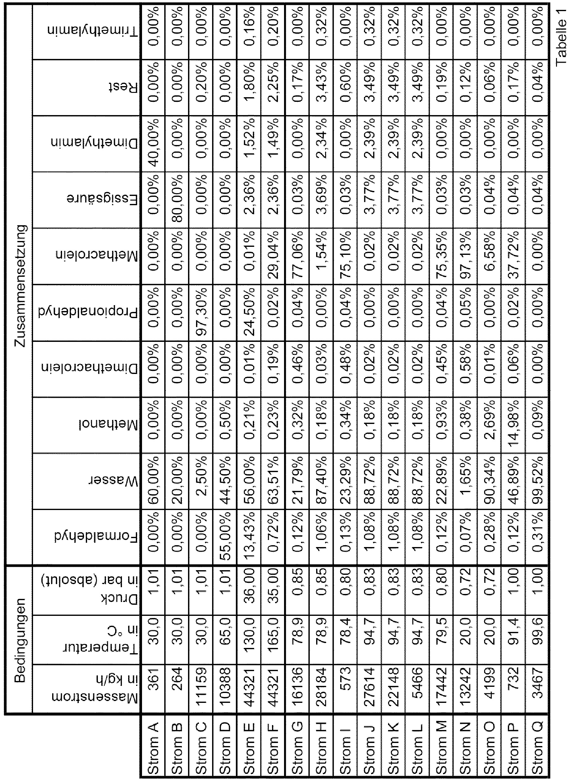
- "Stream A" means: dimethylamine solution stream through the base
supply line arrangement 47, - "Stream B" means: acetic acid solution stream through the acid
feed line arrangement 45, - "Stream C" means: propionaldehyde solution stream through the propionaldehyde
feed line arrangement 43, - "Stream D" means: formaldehyde solution stream through the
formaldehyde feed arrangement 41, - "Stream E" means: stream entering reactor 1,
- "Stream F" means: reaction mixture stream through the reactor
discharge line arrangement 2, - "Stream G" means: stream of the first expansion substance mixture through the first expansion tank
discharge line arrangement 8, - "Stream H" means: stream of the second expansion substance mixture through the second expansion tank
discharge line arrangement 10, - "Stream I" means: stream of the first distillation substance mixture through the first distillation column
discharge line arrangement 14, - "Stream J" means: stream of the second distillation substance mixture through the
first section 29 of the second distillation columndischarge line arrangement 15, - "Stream K" means: stream of the second distillation substance mixture which flows from the
first section 29 of the second distillation columndischarge line arrangement 15 into thesecond section 30 of the second distillation columndischarge line arrangement 15, - "Stream L" means: stream of the second distillation substance mixture which flows from the
first section 29 of the second distillation columndischarge line arrangement 15 into thethird section 31 of the second distillation columndischarge line arrangement 15 and is fed to a disposal, - "Current M" means: current through the collective inlet of the
first capacitor 9, - "Stream N" means: stream of the first separating substance mixture through the first phase separator
discharge line arrangement 21, - "Stream O" means: stream of the second separating substance mixture through the second phase separator
discharge line arrangement 22, - "Stream P" means: stream of the third distillation substance mixture through the third distillation column
discharge line arrangement 26, - "Stream Q" means: stream of the fourth distillation substance mixture through the fourth distillation column
discharge line arrangement 27, - the specification "%" stands for% by weight based on the total mass of the relevant stream and
- the number of decimal places stands for the accuracy of the numerical values.
Aus Tabelle 1 geht hervor, dass der Strom ersten Entspannungsstoffgemisches (Strom G) mit 77,06 Gew.-% Methacrolein einen hohen Methacroleingehalt hat und dagegen der Strom zweiten Entspannungsstoffgemisches (Strom H) mit 1,54 Gew.-% Methacrolein einen geringen Methacroleingehalt hat. Die Trennleistung des Entspannungsbehälters ist also hoch.Table 1 shows that the stream of the first flash substance mixture (stream G) with 77.06% by weight methacrolein has a high methacrolein content and, on the other hand, the flow of the second flash substance mixture (stream H) with 1.54% by weight methacrolein has a low methacrolein content Has. The separation efficiency of the expansion tank is therefore high.
Zudem geht aus Tabelle 1 hervor, dass der Strom ersten Entspannungsstoffgemisches (Strom G) einen Massenstrom von 16.136 kg/h hat. Dieser große Massenstrom wird in den ersten Kondensator 9 geleitet. Er muss also nicht von der ersten Destillationskolonne 11 verarbeitet werden.In addition, Table 1 shows that the stream of the first expansion substance mixture (stream G) has a mass flow of 16,136 kg / h. This large mass flow is passed into the
Ferner geht aus Tabelle 1 hervor, dass der Methacroleingehalt des Stromes ersten Entspannungsstoffgemisches (Strom G) höher sein kann als der des Stromes ersten Destillationsstoffgemisches (Strom I), der im ersten erfindungsgemäßen Versuchsbeispiel 75,10 Gew.-% beträgt.Table 1 also shows that the methacrolein content of the stream of the first flash substance mixture (stream G) can be higher than that of the stream of the first distillation substance mixture (stream I), which in the first inventive test example is 75.10% by weight.
Mit dem Simulationsprogramm Aspen Plus V8.8 der Firma Aspen Technologies, Inc. wurde der erfindungsgemäße Betrieb einer zweiten erfindungsgemäßen Herstellanlage simuliert. Im Gegensatz zu dem ersten erfindungsgemäßen Versuchsbeispiel weist die Herstellanlage des zweiten erfindungsgemäßen Versuchsbeispiels keine zweite Destillationskolonne auf und die zweite Phasentrennerabführleitungsanordnung ist mit der ersten Destillationskolonne fluidisch verbunden. Das Herstellverfahren des zweiten erfindungsgemäßen Versuchsbeispieles weicht dementsprechend vom Herstellverfahren des ersten erfindungsgemäßen Versuchsbeispiels ab. Trotz dieser Abwandlungen werden im Folgenden die Bezugszeichen der ersten Ausführungsform der Erfindung verwendet. The operation according to the invention of a second manufacturing plant according to the invention was simulated with the simulation program Aspen Plus V8.8 from Aspen Technologies, Inc. In contrast to the first experimental example according to the invention, the production plant of the second experimental example according to the invention does not have a second distillation column and the second phase separator discharge line arrangement is fluidically connected to the first distillation column. The production process of the second experimental example according to the invention accordingly deviates from the production process of the first experimental example according to the invention. Despite these modifications, the reference numerals of the first embodiment of the invention are used below.
In der nachfolgenden Tabelle 2 sind der Massenstrom, der Druck, die Temperatur und die Zusammensetzung einiger Ströme des zweiten erfindungsgemäßen Versuchsbeispiels angegeben. In Tabelle 2
- bedeutet "Strom A": Dimethylaminlösungsstrom durch die
Basenzuleitungsanordnung 47, - bedeutet "Strom B": Essigsäurelösungsstrom durch die
Säurenzuleitungsanordnung 45, - bedeutet "Strom C": Propionaldehydlösungsstrom durch die
Propionaldehydzuleitungsanordnung 43, - bedeutet "Strom D": Formaldehydlösungsstrom durch die
Formaldehydzuleitungsanordnung 41, - bedeutet "Strom E": Strom, der in den Reaktor 1 eintritt,
- bedeutet "Strom F": Reaktionsgemischstrom durch die
Reaktorabführleitungsanordnung 2, - bedeutet "Strom G": Strom ersten Entspannungsstoffgemisches durch die erste
Entspannungsbehälterabführleitungsanordnung 8, - bedeutet "Strom H": Strom zweiten Entspannungsstoffgemisches durch die
zweite Entspannungsbehälterabführleitungsanordnung 10, - bedeutet "Strom I": Strom ersten Destillationsstoffgemisches durch die erste
Destillationskolonnenabführleitungsanordnung 14, - bedeutet "Strom J": Strom zweiten Destillationsstoffgemisches durch den ersten
Abschnitt 29 der zweiten Destillationskolonnenabführleitungsanordnung 15, - bedeutet "Strom K": Strom zweiten Destillationsstoffgemisches, welcher vom ersten Abschnitt 29 der zweiten Destillationskolonnenabführleitungsanordnung 15 in
den zweiten Abschnitt 30 der zweiten Destillationskolonnenabführleitungsanordnung 15 strömt, - bedeutet "Strom L": Strom zweiten Destillationsstoffgemisches, welcher vom ersten Abschnitt 29 der zweiten Destillationskolonnenabführleitungsanordnung 15 in
den dritten Abschnitt 31 der zweiten Destillationskolonnenabführleitungsanordnung 15 strömt und einer Entsorgung zugeführt wird, - bedeutet "Strom M": Strom durch den Sammeleinlass des ersten Kondensators 9,
- bedeutet "Strom N": Strom ersten Trennstoffgemisches durch die erste
Phasentrennerabführleitungsanordnung 21, - bedeutet "Strom O": Strom zweiten Trennstoffgemisches durch die
zweite Phasentrennerabführleitungsanordnung 22, - steht die Angabe "%" für Gewichts-% bezogen auf die Gesamtmasse des betreffenden Stromes und
- steht die Anzahl der Kommastellen für die Genauigkeit der Zahlenwerte.

- "Stream A" means: dimethylamine solution stream through the base
supply line arrangement 47, - "Stream B" means: acetic acid solution stream through the acid
feed line arrangement 45, - "Stream C" means: propionaldehyde solution stream through the propionaldehyde
feed line arrangement 43, - "Stream D" means: formaldehyde solution stream through the
formaldehyde feed arrangement 41, - "Stream E" means: stream entering reactor 1,
- "Stream F" means: reaction mixture stream through the reactor
discharge line arrangement 2, - "Stream G" means: stream of the first expansion substance mixture through the first expansion tank
discharge line arrangement 8, - "Stream H" means: stream of the second expansion substance mixture through the second expansion tank
discharge line arrangement 10, - "Stream I" means: stream of the first distillation substance mixture through the first distillation column
discharge line arrangement 14, - "Stream J" means: stream of the second distillation substance mixture through the
first section 29 of the second distillation columndischarge line arrangement 15, - "Stream K" means: stream of the second distillation substance mixture which flows from the
first section 29 of the second distillation columndischarge line arrangement 15 into thesecond section 30 of the second distillation columndischarge line arrangement 15, - "Stream L" means: stream of the second distillation substance mixture which flows from the
first section 29 of the second distillation columndischarge line arrangement 15 into thethird section 31 of the second distillation columndischarge line arrangement 15 and is fed to a disposal, - "Current M" means: current through the collective inlet of the
first capacitor 9, - "Stream N" means: stream of the first separating substance mixture through the first phase separator
discharge line arrangement 21, - "Stream O" means: stream of the second separating substance mixture through the second phase separator
discharge line arrangement 22, - the specification "%" stands for% by weight based on the total mass of the relevant stream and
- the number of decimal places stands for the accuracy of the numerical values.
Aus Tabelle 2 geht hervor, dass der Strom ersten Entspannungsstoffgemisches (Strom G) mit 77,59 Gew.-% Methacrolein einen hohen Methacroleingehalt hat und dagegen der Strom zweiten Entspannungsstoffgemisches (Strom H) mit 1,54 Gew.-% Methacrolein einen geringen Methacroleingehalt hat. Die Trennleistung des Entspannungsbehälters ist also auch im zweiten erfindungsgemäßen Versuchsbeispiel hoch.Table 2 shows that the stream of the first flash substance mixture (stream G) with 77.59% by weight methacrolein has a high methacrolein content and, on the other hand, the flow of the second flash substance mixture (stream H) with 1.54% by weight methacrolein has a low methacrolein content Has. The separation efficiency of the expansion tank is also high in the second test example according to the invention.
Zudem geht aus Tabelle 2 hervor, dass der Strom ersten Entspannungsstoffgemisches (Strom G) einen Massenstrom von 16.044 kg/h hat. Dieser große Massenstrom wird in den ersten Kondensator 9 geleitet. Er muss also nicht von der ersten Destillationskolonne 11 verarbeitet werden.In addition, it can be seen from Table 2 that the flow of the first expansion substance mixture (flow G) has a mass flow of 16,044 kg / h. This large mass flow is passed into the
Ferner geht aus Tabelle 2 hervor, dass der Methacroleingehalt des Stromes ersten Entspannungsstoffgemisches (Strom G) sogar deutlich höher sein kann als der des Stromes ersten Destillationsstoffgemisches (Strom I), der im zweiten erfindungsgemäßen Versuchsbeispiel 57,50 Gew.-% beträgt.Table 2 also shows that the methacrolein content of the stream of the first flash substance mixture (stream G) can even be significantly higher than that of the stream of the first distillation substance mixture (stream I), which in the second inventive test example is 57.50% by weight.
Claims (20)
Priority Applications (7)
| Application Number | Priority Date | Filing Date | Title |
|---|---|---|---|
| EP19194665.6A EP3786146A1 (en) | 2019-08-30 | 2019-08-30 | Method for producing methacrolein from formaldehyde and propionaldehyde and production plant therefor |
| CN202080060990.1A CN114302869B (en) | 2019-08-30 | 2020-08-20 | Method for producing methacrolein from formaldehyde and propionaldehyde and production apparatus for the method |
| EP20756895.7A EP4021879A1 (en) | 2019-08-30 | 2020-08-20 | Method for producing methacrolein from formaldehyde and propionaldehyde, and production plant therefor |
| US17/753,232 US11542218B2 (en) | 2019-08-30 | 2020-08-20 | Process for preparing methacrolein from formaldehyde and propionaldehyde and preparation plant for the purpose |
| JP2022513392A JP2022546460A (en) | 2019-08-30 | 2020-08-20 | Method for producing methacrolein from formaldehyde and propionaldehyde, and apparatus for producing the same |
| PCT/EP2020/073355 WO2021037671A1 (en) | 2019-08-30 | 2020-08-20 | Method for producing methacrolein from formaldehyde and propionaldehyde, and production plant therefor |
| TW109129053A TW202116716A (en) | 2019-08-30 | 2020-08-26 | Process for preparing methacrolein from formaldehyde and propionaldehyde and preparation plant for the purpose |
Applications Claiming Priority (1)
| Application Number | Priority Date | Filing Date | Title |
|---|---|---|---|
| EP19194665.6A EP3786146A1 (en) | 2019-08-30 | 2019-08-30 | Method for producing methacrolein from formaldehyde and propionaldehyde and production plant therefor |
Publications (1)
| Publication Number | Publication Date |
|---|---|
| EP3786146A1 true EP3786146A1 (en) | 2021-03-03 |
Family
ID=67810508
Family Applications (2)
| Application Number | Title | Priority Date | Filing Date |
|---|---|---|---|
| EP19194665.6A Ceased EP3786146A1 (en) | 2019-08-30 | 2019-08-30 | Method for producing methacrolein from formaldehyde and propionaldehyde and production plant therefor |
| EP20756895.7A Pending EP4021879A1 (en) | 2019-08-30 | 2020-08-20 | Method for producing methacrolein from formaldehyde and propionaldehyde, and production plant therefor |
Family Applications After (1)
| Application Number | Title | Priority Date | Filing Date |
|---|---|---|---|
| EP20756895.7A Pending EP4021879A1 (en) | 2019-08-30 | 2020-08-20 | Method for producing methacrolein from formaldehyde and propionaldehyde, and production plant therefor |
Country Status (6)
| Country | Link |
|---|---|
| US (1) | US11542218B2 (en) |
| EP (2) | EP3786146A1 (en) |
| JP (1) | JP2022546460A (en) |
| CN (1) | CN114302869B (en) |
| TW (1) | TW202116716A (en) |
| WO (1) | WO2021037671A1 (en) |
Cited By (1)
| Publication number | Priority date | Publication date | Assignee | Title |
|---|---|---|---|---|
| WO2023031386A1 (en) | 2021-09-06 | 2023-03-09 | Röhm Gmbh | Optimized catalyst processing and recycling in the synthesis of methacrolein |
Citations (7)
| Publication number | Priority date | Publication date | Assignee | Title |
|---|---|---|---|---|
| DE3213681A1 (en) | 1982-04-14 | 1983-10-27 | Basf Ag, 6700 Ludwigshafen | METHOD FOR PRODUCING (ALPHA) ALKYLACROLEINS |
| EP2829531A1 (en) | 2013-07-24 | 2015-01-28 | Evonik Industries AG | Method for regulating the water content in a continuous process for producing methacrolein |
| WO2015065610A1 (en) | 2013-10-28 | 2015-05-07 | Rohm And Haas Company | Process for separating methacrolein |
| WO2016042000A1 (en) | 2014-09-18 | 2016-03-24 | Evonik Röhm Gmbh | Optimized method for producing methacrolein |
| WO2018127963A1 (en) | 2017-01-06 | 2018-07-12 | 日本電気株式会社 | Pattern generation device, image processing device, pattern generation method, and storage medium on which program is stored |
| WO2018217961A1 (en) | 2017-05-25 | 2018-11-29 | Rohm And Haas Company | Process for preparing methacrolein |
| WO2018217964A1 (en) | 2017-05-25 | 2018-11-29 | Rohm And Haas Company | Process for preparing methacrolein |
Family Cites Families (7)
| Publication number | Priority date | Publication date | Assignee | Title |
|---|---|---|---|---|
| GB9207756D0 (en) * | 1992-04-07 | 1992-05-27 | Davy Mckee London | Process |
| CN102442892B (en) * | 2010-10-08 | 2015-04-15 | 中国石油化工股份有限公司 | Preparation method of unsaturated aldehyde by aldehyde condensation |
| KR102213622B1 (en) | 2013-04-19 | 2021-02-08 | 룀 게엠베하 | Method for producing methylmethacrylate |
| SG11201600170PA (en) | 2013-07-24 | 2016-02-26 | Evonik Roehm Gmbh | Recirculation and disposal of aqueous catalyst solutions in amine catalytic processes |
| SG11201601069PA (en) | 2013-09-26 | 2016-03-30 | Evonik Roehm Gmbh | Method for producing methacrolein and the conditioning/draining thereof for direct oxidative esterification |
| EP3023408A1 (en) | 2014-11-19 | 2016-05-25 | Evonik Röhm GmbH | Optimised method for the production of methacrylic acid |
| EP3613726A1 (en) | 2018-08-21 | 2020-02-26 | Röhm GmbH | Continuous process for preparing methacrolein |
-
2019
- 2019-08-30 EP EP19194665.6A patent/EP3786146A1/en not_active Ceased
-
2020
- 2020-08-20 US US17/753,232 patent/US11542218B2/en active Active
- 2020-08-20 EP EP20756895.7A patent/EP4021879A1/en active Pending
- 2020-08-20 CN CN202080060990.1A patent/CN114302869B/en active Active
- 2020-08-20 WO PCT/EP2020/073355 patent/WO2021037671A1/en active Application Filing
- 2020-08-20 JP JP2022513392A patent/JP2022546460A/en active Pending
- 2020-08-26 TW TW109129053A patent/TW202116716A/en unknown
Patent Citations (8)
| Publication number | Priority date | Publication date | Assignee | Title |
|---|---|---|---|---|
| DE3213681A1 (en) | 1982-04-14 | 1983-10-27 | Basf Ag, 6700 Ludwigshafen | METHOD FOR PRODUCING (ALPHA) ALKYLACROLEINS |
| EP2829531A1 (en) | 2013-07-24 | 2015-01-28 | Evonik Industries AG | Method for regulating the water content in a continuous process for producing methacrolein |
| WO2015065610A1 (en) | 2013-10-28 | 2015-05-07 | Rohm And Haas Company | Process for separating methacrolein |
| WO2016042000A1 (en) | 2014-09-18 | 2016-03-24 | Evonik Röhm Gmbh | Optimized method for producing methacrolein |
| WO2018127963A1 (en) | 2017-01-06 | 2018-07-12 | 日本電気株式会社 | Pattern generation device, image processing device, pattern generation method, and storage medium on which program is stored |
| WO2018217961A1 (en) | 2017-05-25 | 2018-11-29 | Rohm And Haas Company | Process for preparing methacrolein |
| WO2018217964A1 (en) | 2017-05-25 | 2018-11-29 | Rohm And Haas Company | Process for preparing methacrolein |
| WO2018217963A1 (en) * | 2017-05-25 | 2018-11-29 | Rohm And Haas Company | Process for preparing methacrolein |
Cited By (1)
| Publication number | Priority date | Publication date | Assignee | Title |
|---|---|---|---|---|
| WO2023031386A1 (en) | 2021-09-06 | 2023-03-09 | Röhm Gmbh | Optimized catalyst processing and recycling in the synthesis of methacrolein |
Also Published As
| Publication number | Publication date |
|---|---|
| WO2021037671A1 (en) | 2021-03-04 |
| CN114302869B (en) | 2024-01-26 |
| TW202116716A (en) | 2021-05-01 |
| US11542218B2 (en) | 2023-01-03 |
| EP4021879A1 (en) | 2022-07-06 |
| CN114302869A (en) | 2022-04-08 |
| JP2022546460A (en) | 2022-11-04 |
| US20220289656A1 (en) | 2022-09-15 |
Similar Documents
| Publication | Publication Date | Title |
|---|---|---|
| EP2295375B1 (en) | Method and device for processing waste sulphuric acids from nitration processes | |
| EP1602640B1 (en) | Process for separation of aqueous amine solutions by distillation | |
| EP1876142B1 (en) | Process and installation for concentrating waste sulphuric acids from nitration processes | |
| DE102005032430A1 (en) | Process for the preparation of toluenediamine | |
| EP2054370A1 (en) | Integrated process and apparatus for preparing esters of methacrylic acid from acetone and hydrocyanic acid | |
| EP0236839B1 (en) | Process for working up aqueous amine solutions | |
| EP3024812A1 (en) | Method of regulating the water content in a continuous method for producing methacrolein | |
| WO2008068063A1 (en) | Process and apparatus for preparing alkyl esters of methacrylic acid | |
| EP2844635B1 (en) | Method for treating a material mixture comprising an aromatic amine, in particular raw aniline | |
| EP1615876A1 (en) | Method for the purification of dimethylacetamide (dmac) | |
| DE102010038519A1 (en) | Process for the preparation of nitrobenzene by adiabatic nitration | |
| EP3277657B1 (en) | Production of tert-butyl esters of aliphatic carboxylic acids | |
| EP3080067A1 (en) | Tertiary alkylamines as methacrolein synthesis co-catalyst | |
| WO2021037671A1 (en) | Method for producing methacrolein from formaldehyde and propionaldehyde, and production plant therefor | |
| EP2809644B1 (en) | Method and device for manufacturing nitrobenzol | |
| EP4021878B1 (en) | Method for producing methacrolein from formaldehyde and propionaldehyde and production plant therefor | |
| EP1473068B1 (en) | Process for the preparation of pure triethylendiamine (TEDA) | |
| EP2953919B1 (en) | Process for the separation of acrolein from the process gas from the heterogeneously catalyzed oxidation of propene | |
| DE19943219A1 (en) | Process for the preparation of dimethyl ether | |
| DE19920741A1 (en) | Concentration of nitric acid or separation of other mixtures forming azeotrope by extractive distillation uses process heat for heating feed and recycled, very concentrated extractant | |
| EP0885873A1 (en) | Methanolysis of the residue from the raw ester distillation in a Witten-Hercules process for the preparation of dimethylterephthalate |
Legal Events
| Date | Code | Title | Description |
|---|---|---|---|
| PUAI | Public reference made under article 153(3) epc to a published international application that has entered the european phase |
Free format text: ORIGINAL CODE: 0009012 |
|
| STAA | Information on the status of an ep patent application or granted ep patent |
Free format text: STATUS: THE APPLICATION HAS BEEN PUBLISHED |
|
| AK | Designated contracting states |
Kind code of ref document: A1 Designated state(s): AL AT BE BG CH CY CZ DE DK EE ES FI FR GB GR HR HU IE IS IT LI LT LU LV MC MK MT NL NO PL PT RO RS SE SI SK SM TR |
|
| AX | Request for extension of the european patent |
Extension state: BA ME |
|
| STAA | Information on the status of an ep patent application or granted ep patent |
Free format text: STATUS: THE APPLICATION HAS BEEN REFUSED |
|
| 18R | Application refused |
Effective date: 20210322 |