EP3786095A1 - Low overhead compensatory measure - Google Patents
Low overhead compensatory measure Download PDFInfo
- Publication number
- EP3786095A1 EP3786095A1 EP19315104.0A EP19315104A EP3786095A1 EP 3786095 A1 EP3786095 A1 EP 3786095A1 EP 19315104 A EP19315104 A EP 19315104A EP 3786095 A1 EP3786095 A1 EP 3786095A1
- Authority
- EP
- European Patent Office
- Prior art keywords
- elevator car
- stop
- stops
- deployed position
- working platform
- Prior art date
- Legal status (The legal status is an assumption and is not a legal conclusion. Google has not performed a legal analysis and makes no representation as to the accuracy of the status listed.)
- Pending
Links
Images




Classifications
-
- B—PERFORMING OPERATIONS; TRANSPORTING
- B66—HOISTING; LIFTING; HAULING
- B66B—ELEVATORS; ESCALATORS OR MOVING WALKWAYS
- B66B11/00—Main component parts of lifts in, or associated with, buildings or other structures
- B66B11/02—Cages, i.e. cars
- B66B11/0226—Constructional features, e.g. walls assembly, decorative panels, comfort equipment, thermal or sound insulation
- B66B11/0246—Maintenance features
-
- B—PERFORMING OPERATIONS; TRANSPORTING
- B66—HOISTING; LIFTING; HAULING
- B66B—ELEVATORS; ESCALATORS OR MOVING WALKWAYS
- B66B5/00—Applications of checking, fault-correcting, or safety devices in elevators
- B66B5/0043—Devices enhancing safety during maintenance
- B66B5/005—Safety of maintenance personnel
-
- B—PERFORMING OPERATIONS; TRANSPORTING
- B66—HOISTING; LIFTING; HAULING
- B66B—ELEVATORS; ESCALATORS OR MOVING WALKWAYS
- B66B5/00—Applications of checking, fault-correcting, or safety devices in elevators
- B66B5/0043—Devices enhancing safety during maintenance
- B66B5/005—Safety of maintenance personnel
- B66B5/0056—Safety of maintenance personnel by preventing crushing
- B66B5/0062—Safety of maintenance personnel by preventing crushing by devices, being operable or not, mounted on the elevator car
-
- B—PERFORMING OPERATIONS; TRANSPORTING
- B66—HOISTING; LIFTING; HAULING
- B66B—ELEVATORS; ESCALATORS OR MOVING WALKWAYS
- B66B5/00—Applications of checking, fault-correcting, or safety devices in elevators
- B66B5/0087—Devices facilitating maintenance, repair or inspection tasks
-
- B—PERFORMING OPERATIONS; TRANSPORTING
- B66—HOISTING; LIFTING; HAULING
- B66B—ELEVATORS; ESCALATORS OR MOVING WALKWAYS
- B66B9/00—Kinds or types of lifts in, or associated with, buildings or other structures
Definitions
- This disclosure relates to an elevator car with a working platform used to carry out maintenance from inside an elevator car, and in particular to measures to ensure a sufficient safety space for workers on the working platform.
- an elevator car comprising: a working platform moveable between a stowed position, at an upper part of the elevator car, and an operational position, suspended from the upper part of the elevator car to be inside the elevator car; at least one stop located at the upper part of the elevator car, wherein the at least one stop is moveable between a retracted position and a deployed position, and wherein, in the deployed position, the at least one stop extends away from the upper part of the elevator car to provide an upper safety space above the elevator car.
- a method of of creating a safety space above an elevator car comprising: a working platform moveable between a stowed position, at an upper part of the elevator car, and an operational position, suspended from the upper part of the elevator car to be inside the elevator car; the method comprising: attaching at least one stop at the upper part of the elevator car, such that the stop is moveable between a retracted position and a deployed position; wherein, in the deployed position, the at least one stop extends away from the upper part of the elevator car to provide an upper safety space above the elevator car.
- a method of employing a safety space above an elevator car comprising a working platform moveable between a stowed position, at an upper part of the elevator car, and an operational position, suspended from the upper part of the elevator car to be inside the elevator car; and at least one stop located at the upper part of the elevator car; the method comprising: moving the working platform to the operational position inside the elevator car; standing on the working platform, so as to protrude through the upper part of the elevator car; and manually operating the at least one stop to move the at least one stop from a retracted position to a deployed position, in which the at least one stop extends away from the upper part of the elevator car to provide an upper safety space above the elevator car.
- such a method may further comprise: locking the at least one stop in the deployed position using a locking mechanism.
- the at least one stop can be deployed to create a safety space above the car when a maintenance person is stood on the working platform.
- the at least one stop lies transversely across the upper part of the elevator car in the retracted position. In at least some examples, the at least one stop lies diagonally across the upper part of the elevator car in the retracted position.
- a choice may be made about whether to accommodate the at least one stop transversely or diagonally depending e.g. on the length of the stop(s). In some examples, a longer stop may help to meet safety code requirements for the upper safety space above the elevator car.
- a stop can be made longer in a diagonal arrangement as compared to a transverse arrangement. This may avoid the at least one stop extending horizontally beyond the footprint of the elevator car, and/or reduce the height above of the elevator car of any attachment for the at least one stop, thereby saving spacing in one or more dimensions of the hoistway.
- the at least one stop comprises a first stop and a second stop located at opposed sides of the upper part of the elevator car.
- the first and second stops lie transversely across the upper part of the elevator car in the retracted position, and extend away from the upper part of the elevator car substantially offset from one another in the deployed position.
- the first stop is located towards the front of the upper part of the elevator car and the second stop is located towards the rear of the upper part of the elevator car. Since the first and second stops are offset from one another, this helps to ensure that the stops do not interfere with one another, particularly when in the retracted position. Both the first and second stops can lie across the upper part of the elevator car in the same plane, minimising the overhead space required.
- the first and second stops lie diagonally across the upper part of the elevator car in the retracted position, and extend away from the upper part of the elevator car substantially opposite one another in the deployed position. Again, both the first and second stops can lie across the upper part of the elevator car in the same plane, minimising the overhead space required. Furthermore, when the first and second stops extend opposite to each other, there is neither a risk of creating a torque when hitting the top of the hoistway nor is there a risk of creating an imbalance in weight of the elevator car.
- the stops can potentially be made longer when they lie diagonally.
- a stop which lies transversely in the retracted position if a stop is required which is longer than the width of the car (i.e. if placed transversely it would extend horizontally beyond the footprint of the car) then either the stop must be extended further beyond the car footprint, which would then require a wider hoistway, or, as described below, a mounting bracket could be made to extend higher above the car, thus requiring a taller hoistway.
- a diagonal arrangement allows for the stop(s) to be made longer, without necessarily requiring further space (either as additional width or height) in the hoistway to accommodate the longer stop. This may be exploited even in examples having a single stop..
- the at least one stop is hinged to move between the retracted position and the deployed position.
- the at least one stop may be hinged around a point which is above the upper part of the elevator car.
- the at least one stop in addition or alternatively, in the retracted position, extends horizontally beyond the footprint of the elevator car. As mentioned above, this may depend on the length of the at least one stop and whether the at least one stop lies transversely or diagonally across the upper part of the elevator car in the retracted position.
- the elevator car further comprises at least one upright, wherein the at least one stop is attached to the at least one upright.
- the elevator car may further comprise a mounting bracket arranged to connect the stop to the upright.
- the mounting bracket may provide a hinged connection between the at least one stop and the upright.
- the mounting bracket may provide a mating connection between the at least one stop and the upright. For example, a mating connection may allow the at least one stop to be received in a correspondingly shaped recess in the upright.
- the at least one stop is configured to be manually operated to move between the retracted position and the deployed position.
- the elevator car further comprises a locking mechanism arranged to lock the at least one stop in the deployed position.
- the locking mechanism comprises a locking pin.
- the locking pin may be configured such that, when the at least one stop is in the deployed position, the locking pin is moveable to a locking position.
- the locking pin may be manually or automatically moveable to the locking position.
- the locking mechanism comprises a spring arranged to bias the locking pin into the locking position. In the locking position, the pin may intersect the at least one stop to hold the at least one stop in the deployed position.
- the at least one stop further comprises a buffer portion, at the distal end of the stop.
- the buffer portion may be formed of any suitable resilient, e.g. elastomeric material, such as rubber.
- the elevator car further comprises a roof frame located at the upper part of the elevator car, wherein the working platform sits within the roof frame in the stowed position to define the roof of the elevator car.
- the working platform is suspended from the roof frame.
- the roof frame may therefore act as a support frame for the working platform. It will be appreciated that it is standard practice for an elevator car to be completely enclosed by walls, floor and a roof.
- the at least one stop in the deployed position, extends substantially perpendicular to the roof frame. This can help to ensure that the at least one stop is stable in the deployed position.
- the at least one stop in addition or alternatively, in the retracted position, lies substantially parallel to the roof frame. This can ensure that the at least one stop does not take up unnecessary space above the elevator car when not in use.
- an elevator system comprising an elevator car according to any of the disclosed examples, and a drive mechanism arranged to drive the elevator car up and down in a hoistway.
- Figure 1a shows an example of an elevator car 1 including a roof frame 2 located at the upper part 3 of the elevator car 1. Within the roof frame 2 is located a working platform 4, in its stowed position, to form the roof of the elevator car 1. When in this stowed position, a decorative ceiling panel 14 can be placed beneath the bottom of the working platform 4, so that the decorative ceiling panel 14 will partially or fully obscure the working platform 4 from the view of a passenger located within the elevator car 1.
- Figure 1a shows the decorative ceiling panel 14 as having been hinged open to reveal the working platform 4, and hanging down towards a wall of the elevator car 1, however, in other embodiments the decorative ceiling panel 14 may simply be removed entirely from its position covering the working platform 4 and placed elsewhere.
- the working platform 4 can be removed from the stowed position and moved downwards into the elevator car 1, as is shown in Figure 1b , and ultimately into the operational position suspended from the roof frame 2 and hanging down inside the elevator car 1, as shown in Figure 1c .
- the working platform may instead be suspended from the walls or attached to any other suitable part of the elevator car 1.
- a maintenance person may stand on the working platform 4, such that, when stood fully upright, a portion of the top part of the maintenance person's body will protrude through the opening in the roof frame 2, into the hoistway. From this position the maintenance person can access many of the elevator system components which are located within the elevator hoistway, and thus perform essential maintenance.
- the safety regulations specify two different safety space allowances. If a refuge, or safety space, has horizontal dimensions of at least 0.5 m x 0.7 m, then it is sufficient to provide a maintenance person with a safety space of a height of 1 m, in which they can crouch.
- a refuge or safety space
- the safety space will only need to be 1m tall. This is generally less than the distance from the working platform 4 in the operational position to the roof frame 2 at the top of the elevator car, and hence the space within the elevator car 1 will be sufficient to provide the necessary safety space.
- the elevator car 1 has small horizontal dimensions, smaller than 0.5 m x 0.7 m, as is sometimes desirable, then a so-called "type 1", or upright, safety space is required.
- minimum horizontal dimensions of 0.4 m x 0.5 m must be provided in the safety space, but also the protected space must now be sufficiently tall to allow a maintenance person to safely stand upright in the safety space and be protected.
- the space within the elevator car 1, above the working platform 4, and below the roof frame 2 is usually not sufficient, as a minimum height of 2 m is required for the safety space.
- the elevator car 1 comprises a first stop 6a and a second stop 6b.
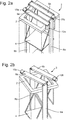
- the elevator car 1, and in particular the first stop 6a and the second stop 6b, are shown in more detail, in the retracted position, in Figure 2a and Figure 3a .
- An alternative arrangement for the first and second stops 6a, 6b in the retracted position is shown in Figure 2b and Figure 3b . Description is given below of certain features which first stop 6a may optionally have. It will be understood by the skilled person that second stop 6b, and any other additional stops included in the elevator car 1, may optionally have any of these features, according to examples of the present disclosure.
- the stop 6a can be attached to the elevator car 1 in any suitable way.
- the stop 6a could be attached to the elevator car 1 only in its deployed position, described below, for example one or more such stops 6a could be received in a correspondingly shaped recess to form a mating connection which holds each stop 6a upright in the deployed position.
- the stop 6a could be attached at all times to the elevator car 1.
- the stop 6a may be attached directly to the roof frame 2.
- the stop 6a is attached to a mounting bracket 12a in this example.
- the opposite stop 6b is attached to a mounting bracket 12b. There is a hinged connection between the stops 6a, 6b and the mounting brackets 12a, 12b.
- the mounting brackets 12a, 12b are attached to the car uprights 8a, 8b.
- the car uprights 8a, 8b are common elevator system components that do not require any further description.
- the stops 6a, 6b are arranged to pivot between the retracted position and the deployed position, as described below.
- the stops 6a, 6b may be attached directly to the car uprights 8a, 8b.
- the stop 6a comprises a buffer portion 10a at the distal end of the stop 6a.
- the stop 6b comprises a buffer portion 10b at the distal end of the stop 6b.
- the buffer portions 10a, 10b may be formed of rubber or any other resilient material.
- the distal end of each of the stops 6a, 6b will be understood by the skilled person as the end of the stop 6a, 6b which is furthest from the mounting bracket 12a, 12b, which is also the end furthest from the elevator car 1, when the stop 6a, 6b is in the deployed position.
- the stops 6a, 6b are manually operable to move between the retracted position and the deployed position i.e. moved by hand by a maintenance person.
- the stops 6a, 6b are in the deployed position, extending away from the upper part 3 of the elevator car 1 to provide an upper safety space above the elevator car 1, in addition to the internal safety space created inside the elevator car 1, from the working platform 4 to the roof e.g. roof frame 2. Together the internal safety space and the upper safety space create a total safety space which is sufficient to meet code requirements.
- the stops 6a, 6b need not be fully vertical in the deployed position, and could be located at an angle of less than 90 degrees to the horizontal plane as defined by the roof e.g. roof frame 2.
- the stops 6a, 6b are substantially vertical in the deployed position i.e. substantially perpendicular to the horizontal plane as defined by the roof e.g. roof frame 2.
- the stops 6a, 6b can be fixed in the deployed position using a locking mechanism shown in more detail in Figures 6a and 6b and Figures 7a and 7b , and discussed in more detail below, with reference to these Figures.
- the stops 6a, 6b are arranged to provide an extension of the structural part of the elevator car 1 i.e. an extension of the uprights 8a, 8b, so that if the elevator car 1 were to move, uncontrolled, upwards in the hoistway then the stops 6a, 6b and in particular the buffer portions 10a, 10b will contact the top of the hoistway and prevent further movement, guaranteeing a maintenance person a total safety space sufficient to meet code requirements.
- Figure 5a shows a side view of an elevator car 1 according to an example of the present disclosure, including first stop 6a, and optional second stop 6b, in the deployed position, and showing a total safety space 16 made up of an internal safety space 51, extending from the working platform 4 to the upper part 3 of the elevator car 1, and an upper safety space 53, created above the elevator car 1 by the stops 6a, 6b.
- Figure 5b shows a perspective view of the elevator car 1 of Figure 5a , including the total safety space 16.
- Figure 5c shows a front view of the elevator car 1 of Figures 5a and 5b , including the total safety space 16.
- the first stop 6a is offset from the second stop 6b, in the front/back direction as defined by the elevator car 1 i.e. the first stop 6a is located further forward on the elevator car 1 than the second stop 6a (or vice versa).
- the first stop 6a is attached to the upright 8a on the side that is nearer to the front of the elevator car 1 (i.e. nearer to the left in Figure 5a ), whilst the second stop 6b is attached to the upright 8b (not visible in Figure 5a ), on the opposed side of the elevator car 1, and located closer to the rear of the elevator car 1 (i.e. nearer to the right in Figure 5a ).
- each stop 6a, 6b is hinged to fold down from the deployed position to the retracted position, and to lie substantially horizontally above the roof e.g. roof frame 2. If, as an alternative to the offset stop layout described above, each stop 6a, 6b were to be attached at the same distance from the front of the elevator car 1, on opposed side walls, then the stops 6a, 6b would interfere with each other when folded down into the retracted position. One of the stops would have to lie on top of the other stop, which would thus increase the height of the stops in the retracted position and so have the negative effect of increasing the overhead height required for the elevator car 1.
- each stop 6a, 6b can be folded into a retracted position as shown in Figure 2a and Figure 3a , in which each stop 6a, 6b, lies substantially horizontally over separate, different parts of the roof e.g. roof frame 2, such that each stop 6a, 6b can be folded substantially horizontally to its lowest possible height, thus reducing the overhead height required by the stops 6a, 6b in their retracted position to its minimum value.
- FIG. 2b , 3c , 3d and 4b An alternative to this arrangement is shown in Figures 2b , 3c , 3d and 4b .
- the stops 6a and 6b are attached to the elevator car in positions which are substantially opposite each other i.e. each stop 6a,6b is attached at the same distance along the elevator car in the front/back direction, but the stops 6a,6b are arranged to lie diagonally across the upper part 3 of the elevator car.
- the stops 6a, 6b are not attached to mounting brackets, but instead attached directly to the car uprights 8a, 8b by any suitable mounting arrangement.
- the stops 6a, 6b can be arranged to remain substantially diagonal to the roof frame 2 in the deployed position.
- a suitable connection could be used to connect the stops 6a, 6b to the respective uprights 8a, 8b such that, as the stops 6a, 6b are moved from the retracted to the deployed position, the stops 6a, 6b rotate from a diagonal configuration to face each other directly across the roof e.g. as defined by the roof frame 2, i.e. facing in the same direction as the stops 6a, 6b shown in Figure 3b .
- the stops 6a, 6b may not be attached to the car uprights 8a, 8b in a hinged manner.
- the stops 6a, 6b could be placed in the diagonal arrangement shown in Figure 3c , in the retracted position, and then removed from this position and locked in the deployed position shown in Figure 3d and 4b .
- An example of a locking mechanism is described below, in relation to Figures 6 and 7 .
- the mounting brackets 12a, 12b (or other mounting arrangement) for the stops 6a, 6b are arranged so that the stops 6a, 6b hinge around the top edge of the roof frame 2.
- the stops 6a, 6b are arranged to hinge about a point which is located above the top of the roof e.g. as defined by the roof frame 2.
- the mounting brackets 12a, 12b extend to the top of the uprights 8a, 8b, which extend above the top of the elevator car 1, and in particular above the top of the roof e.g. roof frame 2. This additional vertical offset allows the total height created by the stops 6a, 6b to be adjusted for the desired height of the safety space 16.
- a maintenance person is provided with a total safety space 16 of a height of at least 2 metres.
- This total safety space height of 2 m is indicated in Figure 5c by the arrow 50.
- the working platform 4 can sit, in the operational position, at any height within the elevator car 1, as described.
- the operational position of the working platform 4 is between 1-1.1 m below the roof, e.g. as defined by the roof frame 2 in these examples.
- the operational position of the working platform 4 is 1.1 m below the roof (e.g. as defined by the roof frame 2 in these examples), as represented by arrow 52. This is thus the height of the internal safety space 51.
- This is particularly advantageous since it allows a substantial portion of a maintenance person's body to be located within the elevator car 1, whilst also allowing them sufficient reach into the elevator hoistway to carry out maintenance work.
- the total extension above the elevator car 1 provided by the stops 6a, 6b must therefore be at least 0.9 m, i.e. the upper safety space 53 created by the stops 6a, 6b must be at least 0.9 m.
- the width of the elevator car 1 may be less than 0.9 m, for example the width of the elevator car 1 may be 0.8 m or 0.7 m. In such a case, if the stops 6a, 6b hinged directly around the top of the roof frame 2, the stops 6a, 6b would need to be of a length of 0.9 m, and would therefore extend, in the retracted position, far outside of the footprint of the elevator car 1.
- the mounting brackets 12a, 12b extend above the top of the roof frame 2, and the stops 6a, 6b are hinged about the top of the mounting brackets 12a, 12b, so that this offset contributes to the total height of the stop arrangement in the deployed position.
- the total extension height 54 of the upper safety space 53 of 0.9 m is thus made up both of the length of the stop 56 and the offset distance 58 between the top of the mounting bracket 12a and the top of the roof frame 2 (as seen in Figure 5a ), which allows the length of the stops 6a, 6b to be reduced.
- the stops 6a, 6b may still extend horizontally beyond the footprint of the elevator car 1, as shown in Figure 3a .
- the elevator car 1 includes a roof frame 2 and the working platform 4 is suspended from the roof frame 2.
- the roof frame 2 may be omitted and the working platform 4 may be suspended from the upper part 3 of the elevator car 1 in any suitable way.
- the upper safety space 53 e.g. as seen in Figures 5a-5c ) is defined by the one or more stops 6a, 6b when they extend away from the upper part 3 of the elevator car 1 in the deployed position.
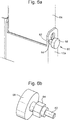
- Figures 6a and 6b show an exemplary locking mechanism 60.
- Figure 6a shows a close up view of the locking mechanism 60 in a locking configuration, locking the stop 6a in the deployed position.
- the locking mechanism 60 shown in more detail in Figure 6b , comprises a pin 62, which is moveable to a locking position (as shown in Figures 6a and 6b ) from a non-locking position (as shown in Figures 7a and 7b ).
- the locking mechanism 60 includes an outer portion 64, which the pin 62 passes through, such that the pin 62 can move axially relative to the outer portion 64.
- the pin 62 includes a grip portion 68, which can be gripped, for example by a maintenance person, and used to pull the pin 62 out of the locking position.
- the outer portion 64 is fixed to a side of the mounting bracket 12a, on the opposite side to the stop 6a.
- the stop 6a is slotted between the two sides of the mounting bracket 12a, adjacent to the internal surfaces of the sides of the mounting bracket 12a, and the outer portion 64 of the locking mechanism 60 is fixed to the exterior surface of one side of the mounting bracket 12a.
- the outer portion 64 is fixed to the mounting bracket 12a directly over a through-hole (not visible) in the mounting bracket 12a, which is suitably sized so that the pin 62 can pass through the through-hole.
- the stop 6a similarly includes a through-hole 66, visible in Figure 7a , which is positioned such that the through-hole 66 aligns with the mounting bracket through-hole when the stop 6a is in the deployed position. In this position the pin 62 can pass through both the through-holes, thus preventing relative movement of the stop 6a with respect to the mounting bracket 12a, and locking the stop 6a in the deployed position.
- Figures 6 and 7 only show a locking mechanism 60 on one side of the stop 6a, it will be appreciated that such a locking mechanism 60 may be employed on either side, or both sides, of the stop 6a.
- the locking mechanism 60 includes an internal spring (not visible), which biases the pin 62 into the locking position.
- the pin 62 is constantly pushed towards the locking position, so that, as soon as the through-holes on the mounting bracket 12a and the stop 6a align, the pin 62 is pushed by the spring into the locking position, passing through both of the through-holes.
- the locking mechanism 60 is thus self-locking and no additional force need be applied by a maintenance person to lock the stop 6a, once it has been moved to the deployed position. This advantageously provides a locking mechanism which is simple to deploy.
- the locking mechanism 60 must be unlocked in order to be able to move the stop 6a from the deployed position to the retracted position.
- the pin 62 is moved out of the locking position by applying a force to the grip portion 68, sufficient to overcome the bias of the internal spring. This force, applied for example by a maintenance person, thus pulls the pin 62 back through the through-hole 66 of the stop 6a, and possibly also through the through-hole of the mounting bracket 12a, while the outer portion 64 stays fixed in position.
- the stop 6a can be freely moved back to the retracted position (as shown in Figure 7a ).
- stops described herein are particularly advantageous in elevator cars having a small horizontal footprint, it will be understood that they can also be advantageous in systems with a larger horizontal footprint and can provide improved safety also in these systems.
Landscapes
- Engineering & Computer Science (AREA)
- Structural Engineering (AREA)
- Civil Engineering (AREA)
- Mechanical Engineering (AREA)
- Automation & Control Theory (AREA)
- Maintenance And Inspection Apparatuses For Elevators (AREA)
Abstract
Description
- This disclosure relates to an elevator car with a working platform used to carry out maintenance from inside an elevator car, and in particular to measures to ensure a sufficient safety space for workers on the working platform.
- It is known to create a safety space above an elevator car by placing props within the pit of an elevator hoistway, below a counterweight travel path, such that movement of the counterweight below a certain height is prevented, and thus movement of an elevator car, to which the counterweight is connected, above a certain height is prevented. This provides a certain safety space in the overhead of the elevator hoistway. However, it is generally desirable to reduce the overhead in elevator systems so that building space is optimised.
- It is also known to provide working platforms located in or above the ceiling of elevator cars, which are moveable between a stowed position and a deployed position. In the deployed position, the working platform is located within the car, at such a height that a maintenance person is able to stand on the working platform and access elevator components inside the hoistway through an opening in the elevator car ceiling. The safety of workers on such a working platform must be ensured at all times.
- According to a first aspect of this disclosure, there is provided an elevator car comprising: a working platform moveable between a stowed position, at an upper part of the elevator car, and an operational position, suspended from the upper part of the elevator car to be inside the elevator car; at least one stop located at the upper part of the elevator car, wherein the at least one stop is moveable between a retracted position and a deployed position, and wherein, in the deployed position, the at least one stop extends away from the upper part of the elevator car to provide an upper safety space above the elevator car.
- According to a second aspect of this disclosure, there is provided a method of of creating a safety space above an elevator car, the elevator car comprising: a working platform moveable between a stowed position, at an upper part of the elevator car, and an operational position, suspended from the upper part of the elevator car to be inside the elevator car; the method comprising: attaching at least one stop at the upper part of the elevator car, such that the stop is moveable between a retracted position and a deployed position; wherein, in the deployed position, the at least one stop extends away from the upper part of the elevator car to provide an upper safety space above the elevator car.
- According to a third aspect of this disclosure, there is provided a method of employing a safety space above an elevator car, the elevator car comprising a working platform moveable between a stowed position, at an upper part of the elevator car, and an operational position, suspended from the upper part of the elevator car to be inside the elevator car; and at least one stop located at the upper part of the elevator car; the method comprising: moving the working platform to the operational position inside the elevator car; standing on the working platform, so as to protrude through the upper part of the elevator car; and manually operating the at least one stop to move the at least one stop from a retracted position to a deployed position, in which the at least one stop extends away from the upper part of the elevator car to provide an upper safety space above the elevator car.
- In at least some examples, such a method may further comprise: locking the at least one stop in the deployed position using a locking mechanism.
- It will be appreciated that the at least one stop can be deployed to create a safety space above the car when a maintenance person is stood on the working platform.
- In at least some examples, in addition or alternatively, the at least one stop lies transversely across the upper part of the elevator car in the retracted position. In at least some examples, the at least one stop lies diagonally across the upper part of the elevator car in the retracted position. A choice may be made about whether to accommodate the at least one stop transversely or diagonally depending e.g. on the length of the stop(s). In some examples, a longer stop may help to meet safety code requirements for the upper safety space above the elevator car. A stop can be made longer in a diagonal arrangement as compared to a transverse arrangement. This may avoid the at least one stop extending horizontally beyond the footprint of the elevator car, and/or reduce the height above of the elevator car of any attachment for the at least one stop, thereby saving spacing in one or more dimensions of the hoistway.
- In at least some examples, in addition or alternatively, the at least one stop comprises a first stop and a second stop located at opposed sides of the upper part of the elevator car. By providing a pair of stops, forces on the elevator car are more balanced in the event that the stops engage against a ceiling of the hoistway when deployed. Furthermore, providing a second stop ensures redundancy in the event that the first stop fails to deploy or due to buckling of one stop.
- In a first set of examples, the first and second stops lie transversely across the upper part of the elevator car in the retracted position, and extend away from the upper part of the elevator car substantially offset from one another in the deployed position. In such examples, optionally the first stop is located towards the front of the upper part of the elevator car and the second stop is located towards the rear of the upper part of the elevator car. Since the first and second stops are offset from one another, this helps to ensure that the stops do not interfere with one another, particularly when in the retracted position. Both the first and second stops can lie across the upper part of the elevator car in the same plane, minimising the overhead space required.
- In a second set of examples, the first and second stops lie diagonally across the upper part of the elevator car in the retracted position, and extend away from the upper part of the elevator car substantially opposite one another in the deployed position. Again, both the first and second stops can lie across the upper part of the elevator car in the same plane, minimising the overhead space required. Furthermore, when the first and second stops extend opposite to each other, there is neither a risk of creating a torque when hitting the top of the hoistway nor is there a risk of creating an imbalance in weight of the elevator car.
- As mentioned above, the stops can potentially be made longer when they lie diagonally. In the case of a stop which lies transversely in the retracted position, if a stop is required which is longer than the width of the car (i.e. if placed transversely it would extend horizontally beyond the footprint of the car) then either the stop must be extended further beyond the car footprint, which would then require a wider hoistway, or, as described below, a mounting bracket could be made to extend higher above the car, thus requiring a taller hoistway. A diagonal arrangement allows for the stop(s) to be made longer, without necessarily requiring further space (either as additional width or height) in the hoistway to accommodate the longer stop. This may be exploited even in examples having a single stop..
- In at least some examples, in addition or alternatively, the at least one stop is hinged to move between the retracted position and the deployed position. For example, the at least one stop may be hinged around a point which is above the upper part of the elevator car.
- In at least some examples, in addition or alternatively, in the retracted position, the at least one stop extends horizontally beyond the footprint of the elevator car. As mentioned above, this may depend on the length of the at least one stop and whether the at least one stop lies transversely or diagonally across the upper part of the elevator car in the retracted position.
- In at least some examples, in addition or alternatively, the elevator car further comprises at least one upright, wherein the at least one stop is attached to the at least one upright. In such examples, the elevator car may further comprise a mounting bracket arranged to connect the stop to the upright. In some examples, the mounting bracket may provide a hinged connection between the at least one stop and the upright. In some examples, the mounting bracket may provide a mating connection between the at least one stop and the upright. For example, a mating connection may allow the at least one stop to be received in a correspondingly shaped recess in the upright.
- In at least some examples, in addition or alternatively, the at least one stop is configured to be manually operated to move between the retracted position and the deployed position.
- In at least some examples, in addition or alternatively, the elevator car further comprises a locking mechanism arranged to lock the at least one stop in the deployed position. In some examples, the locking mechanism comprises a locking pin. For example, the locking pin may be configured such that, when the at least one stop is in the deployed position, the locking pin is moveable to a locking position. The locking pin may be manually or automatically moveable to the locking position. In some examples, the locking mechanism comprises a spring arranged to bias the locking pin into the locking position. In the locking position, the pin may intersect the at least one stop to hold the at least one stop in the deployed position.
- In at least some examples, in addition or alternatively, the at least one stop further comprises a buffer portion, at the distal end of the stop. The buffer portion may be formed of any suitable resilient, e.g. elastomeric material, such as rubber.
- In at least some examples, in addition or alternatively, the elevator car further comprises a roof frame located at the upper part of the elevator car, wherein the working platform sits within the roof frame in the stowed position to define the roof of the elevator car. Optionally, the working platform is suspended from the roof frame. The roof frame may therefore act as a support frame for the working platform. It will be appreciated that it is standard practice for an elevator car to be completely enclosed by walls, floor and a roof.
- In at least some examples, in the deployed position, the at least one stop extends substantially perpendicular to the roof frame. This can help to ensure that the at least one stop is stable in the deployed position.
- In at least some examples, in addition or alternatively, in the retracted position, the at least one stop lies substantially parallel to the roof frame. This can ensure that the at least one stop does not take up unnecessary space above the elevator car when not in use.
- There is also disclosed herein an elevator system comprising an elevator car according to any of the disclosed examples, and a drive mechanism arranged to drive the elevator car up and down in a hoistway.
- Certain preferred examples of this disclosure will now be described, by way of example only, and with reference to the accompanying drawings, in which:
-
Figures 1a, 1b and 1c are cutaway perspective views of an elevator car including a working platform, moveable between a stowed position (as shown inFigure 1a ) and an operational position (as shown inFigure 1c ), according to an example of the present disclosure; -
Figure 2a shows a cutaway perspective view of the upper part of the elevator car ofFigure 1c ; -
Figure 2b shows a cutaway perspective view of the upper part of an elevator car according to an alternative example of the present disclosure; -
Figure 3a shows a view from above of the top of an elevator car according to an example of the present disclosure, with the stops in the retracted position; -
Figure 3b shows a view from above of the top of an elevator car according to an example of the present disclosure, with the stops in the deployed position; -
Figure 3c shows a view from above of the top of an elevator car according to an alternative example of the present disclosure, with the stops in the retracted position; -
Figure 3d shows a view from above of the top of an elevator car according to an alternative example of the present disclosure, with the stops in the deployed position; -
Figure 4a shows a cutaway perspective view of the elevator car ofFigure 3b , with the stops in the deployed position; -
Figure 4b shows a cutaway perspective view of the elevator car ofFigure 3d , with the stops in the deployed position; -
Figures 5a, 5b and 5c are cutaway views, from different perspectives, of an elevator car including stops in the deployed position, and showing the safety space which is created in and above the elevator car according to examples of the present disclosure; -
Figures 6a and 6b schematically illustrate an exemplary locking mechanism for a stop, acting to lock the stop in the deployed position; and -
Figures 7a and 7b schematically illustrate the exemplary locking mechanism being unlocked when the stop is in the retracted position. -
Figure 1a shows an example of anelevator car 1 including aroof frame 2 located at theupper part 3 of theelevator car 1. Within theroof frame 2 is located a workingplatform 4, in its stowed position, to form the roof of theelevator car 1. When in this stowed position, adecorative ceiling panel 14 can be placed beneath the bottom of the workingplatform 4, so that thedecorative ceiling panel 14 will partially or fully obscure the workingplatform 4 from the view of a passenger located within theelevator car 1.Figure 1a shows thedecorative ceiling panel 14 as having been hinged open to reveal the workingplatform 4, and hanging down towards a wall of theelevator car 1, however, in other embodiments thedecorative ceiling panel 14 may simply be removed entirely from its position covering the workingplatform 4 and placed elsewhere. - Once the
decorative ceiling panel 14 has been hinged, or moved, out of the way, the workingplatform 4 can be removed from the stowed position and moved downwards into theelevator car 1, as is shown inFigure 1b , and ultimately into the operational position suspended from theroof frame 2 and hanging down inside theelevator car 1, as shown inFigure 1c . Of course, the working platform may instead be suspended from the walls or attached to any other suitable part of theelevator car 1. - In the operational position, a maintenance person may stand on the working
platform 4, such that, when stood fully upright, a portion of the top part of the maintenance person's body will protrude through the opening in theroof frame 2, into the hoistway. From this position the maintenance person can access many of the elevator system components which are located within the elevator hoistway, and thus perform essential maintenance. - It is important to ensure that the maintenance person is protected when carrying out maintenance in an elevator system. In order to ensure this, safety regulations such as EN81-20 have been introduced. In particular, it is required that a maintenance person be provided with a certain minimum "safety space" in which to work, which is a protected space within the elevator hoistway which a maintenance person can access to perform maintenance, and into which elevator components are prevented from travelling. There exist systems in the prior art in which a maintenance person stands on the top of the elevator car to carry out maintenance work. In these systems it is known to include stops or props within the hoistway pit, to prevent downwards movement of the counterweight below a certain height, and thus prevent the elevator car from ascending beyond a certain height. In this way a safety space is created above the elevator car in which a maintenance person may safely work.
- The safety regulations specify two different safety space allowances. If a refuge, or safety space, has horizontal dimensions of at least 0.5 m x 0.7 m, then it is sufficient to provide a maintenance person with a safety space of a height of 1 m, in which they can crouch. In an
elevator car 1 of the type described above, including a workingplatform 4 which is moved down into theelevator car 1, if the horizontal footprint of the elevator car is sufficiently large then the safety space will only need to be 1m tall. This is generally less than the distance from the workingplatform 4 in the operational position to theroof frame 2 at the top of the elevator car, and hence the space within theelevator car 1 will be sufficient to provide the necessary safety space. - However, if the
elevator car 1 has small horizontal dimensions, smaller than 0.5 m x 0.7 m, as is sometimes desirable, then a so-called "type 1", or upright, safety space is required. In this case, minimum horizontal dimensions of 0.4 m x 0.5 m must be provided in the safety space, but also the protected space must now be sufficiently tall to allow a maintenance person to safely stand upright in the safety space and be protected. In this case, the space within theelevator car 1, above the workingplatform 4, and below theroof frame 2, is usually not sufficient, as a minimum height of 2 m is required for the safety space. - In order to overcome this issue, and create a sufficiently large safety space, at least one
stop 6a is provided above theelevator car 1. In some preferred examples illustrated herein, theelevator car 1 comprises afirst stop 6a and asecond stop 6b. Theelevator car 1, and in particular thefirst stop 6a and thesecond stop 6b, are shown in more detail, in the retracted position, inFigure 2a andFigure 3a . An alternative arrangement for the first andsecond stops Figure 2b andFigure 3b . Description is given below of certain features whichfirst stop 6a may optionally have. It will be understood by the skilled person thatsecond stop 6b, and any other additional stops included in theelevator car 1, may optionally have any of these features, according to examples of the present disclosure. - The
stop 6a can be attached to theelevator car 1 in any suitable way. Thestop 6a could be attached to theelevator car 1 only in its deployed position, described below, for example one or moresuch stops 6a could be received in a correspondingly shaped recess to form a mating connection which holds eachstop 6a upright in the deployed position. Alternatively, thestop 6a could be attached at all times to theelevator car 1. In some examples, thestop 6a may be attached directly to theroof frame 2. Alternatively, as seen inFigure 2a , thestop 6a is attached to a mountingbracket 12a in this example. Similarly, theopposite stop 6b is attached to a mountingbracket 12b. There is a hinged connection between thestops brackets brackets car uprights car uprights stops Figure 2b , thestops car uprights stops car uprights stops - In these examples, the
stop 6a comprises abuffer portion 10a at the distal end of thestop 6a. Similarly, thestop 6b comprises abuffer portion 10b at the distal end of thestop 6b. Thebuffer portions stops stop bracket elevator car 1, when thestop - Once a maintenance person has moved the working
platform 4 to the operational position, and is stood on the workingplatform 4, they are then in a position to be able to move thestops Figures 2a and 2b andFigures 3a and3c , into the deployed position, as shown inFigures 3b and3d , andFigures 4a and 4b . In some examples, thestops - In the example seen in
Figure 3b andFigure 4a , and the example seen inFigure 3d andFigure 4b , thestops upper part 3 of theelevator car 1 to provide an upper safety space above theelevator car 1, in addition to the internal safety space created inside theelevator car 1, from the workingplatform 4 to the roofe.g. roof frame 2. Together the internal safety space and the upper safety space create a total safety space which is sufficient to meet code requirements. Thestops e.g. roof frame 2. However, as illustrated inFigures 3b and3d andFigures 4a and 4b , in these examples thestops e.g. roof frame 2. - Once the maintenance person has moved the
stops stops Figures 6a and 6b andFigures 7a and 7b , and discussed in more detail below, with reference to these Figures. - In the deployed position, the
stops elevator car 1 i.e. an extension of theuprights elevator car 1 were to move, uncontrolled, upwards in the hoistway then thestops buffer portions -
Figure 5a shows a side view of anelevator car 1 according to an example of the present disclosure, includingfirst stop 6a, and optionalsecond stop 6b, in the deployed position, and showing atotal safety space 16 made up of aninternal safety space 51, extending from the workingplatform 4 to theupper part 3 of theelevator car 1, and anupper safety space 53, created above theelevator car 1 by thestops -
Figure 5b shows a perspective view of theelevator car 1 ofFigure 5a , including thetotal safety space 16. -
Figure 5c shows a front view of theelevator car 1 ofFigures 5a and 5b , including thetotal safety space 16. - In the example shown in
Figures 2a ,3a ,3b ,4a , and5a-5c , thefirst stop 6a is offset from thesecond stop 6b, in the front/back direction as defined by theelevator car 1 i.e. thefirst stop 6a is located further forward on theelevator car 1 than thesecond stop 6a (or vice versa). Thefirst stop 6a is attached to the upright 8a on the side that is nearer to the front of the elevator car 1 (i.e. nearer to the left inFigure 5a ), whilst thesecond stop 6b is attached to theupright 8b (not visible inFigure 5a ), on the opposed side of theelevator car 1, and located closer to the rear of the elevator car 1 (i.e. nearer to the right inFigure 5a ). - In some examples, the
elevator car 1 is arranged such that eachstop e.g. roof frame 2. If, as an alternative to the offset stop layout described above, eachstop elevator car 1, on opposed side walls, then thestops elevator car 1. The offset stop layout described above is therefore particularly advantageous since thestops Figure 2a andFigure 3a , in which eachstop e.g. roof frame 2, such that eachstop stops - An alternative to this arrangement is shown in
Figures 2b ,3c ,3d and4b . In this example, thestops stop stops upper part 3 of the elevator car. In this example, thestops car uprights Figure 3d , thestops roof frame 2 in the deployed position. Alternatively, a suitable connection could be used to connect thestops respective uprights stops stops roof frame 2, i.e. facing in the same direction as thestops Figure 3b . - As already mentioned, the
stops car uprights stops Figure 3c , in the retracted position, and then removed from this position and locked in the deployed position shown inFigure 3d and4b . An example of a locking mechanism is described below, in relation toFigures 6 and7 . - In some examples, the mounting
brackets stops stops roof frame 2. In other examples, thestops roof frame 2. For example, it can be seen inFigure 5a , that the mountingbrackets uprights elevator car 1, and in particular above the top of the roofe.g. roof frame 2. This additional vertical offset allows the total height created by thestops safety space 16. - As laid out above, it is desirable according to safety regulations, that in certain circumstances, a maintenance person is provided with a
total safety space 16 of a height of at least 2 metres. This total safety space height of 2 m is indicated inFigure 5c by thearrow 50. The workingplatform 4 can sit, in the operational position, at any height within theelevator car 1, as described. In some examples, the operational position of the workingplatform 4 is between 1-1.1 m below the roof, e.g. as defined by theroof frame 2 in these examples. In some particular examples, the operational position of the workingplatform 4 is 1.1 m below the roof (e.g. as defined by theroof frame 2 in these examples), as represented byarrow 52. This is thus the height of theinternal safety space 51. This is particularly advantageous since it allows a substantial portion of a maintenance person's body to be located within theelevator car 1, whilst also allowing them sufficient reach into the elevator hoistway to carry out maintenance work. - In order to provide the desired
total safety space 16, the total extension above theelevator car 1 provided by thestops upper safety space 53 created by thestops elevator car 1 may be less than 0.9 m, for example the width of theelevator car 1 may be 0.8 m or 0.7 m. In such a case, if thestops roof frame 2, thestops elevator car 1. In order to avoid this, the mountingbrackets roof frame 2, and thestops brackets total extension height 54 of theupper safety space 53 of 0.9 m (as seen inFigure 5c ) is thus made up both of the length of thestop 56 and the offsetdistance 58 between the top of the mountingbracket 12a and the top of the roof frame 2 (as seen inFigure 5a ), which allows the length of thestops stops elevator car 1, as shown inFigure 3a . - The diagonal arrangement shown in
Figures 2b ,3c ,3d and4b provides an advantageous alternative in which longer stops 6a, 6b can be accommodated without requiring additional space either extending outside of the elevator car footprint, or extending above theelevator car 1. Due to their diagonal arrangement, thestops Figure 3c . Furthermore, since this allows longer stops to be provided, thestops Figure 4b , thestops car uprights - In the illustrated examples, the
elevator car 1 includes aroof frame 2 and the workingplatform 4 is suspended from theroof frame 2. However, theroof frame 2 may be omitted and the workingplatform 4 may be suspended from theupper part 3 of theelevator car 1 in any suitable way. Whether or not theelevator car 1 includes aroof frame 2, the upper safety space 53 (e.g. as seen inFigures 5a-5c ) is defined by the one ormore stops upper part 3 of theelevator car 1 in the deployed position. -
Figures 6a and 6b show anexemplary locking mechanism 60.Figure 6a shows a close up view of thelocking mechanism 60 in a locking configuration, locking thestop 6a in the deployed position. In this example, thelocking mechanism 60, shown in more detail inFigure 6b , comprises apin 62, which is moveable to a locking position (as shown inFigures 6a and 6b ) from a non-locking position (as shown inFigures 7a and 7b ). Thelocking mechanism 60 includes anouter portion 64, which thepin 62 passes through, such that thepin 62 can move axially relative to theouter portion 64. Thepin 62 includes agrip portion 68, which can be gripped, for example by a maintenance person, and used to pull thepin 62 out of the locking position. Theouter portion 64 is fixed to a side of the mountingbracket 12a, on the opposite side to thestop 6a. In this example, thestop 6a is slotted between the two sides of the mountingbracket 12a, adjacent to the internal surfaces of the sides of the mountingbracket 12a, and theouter portion 64 of thelocking mechanism 60 is fixed to the exterior surface of one side of the mountingbracket 12a. Theouter portion 64 is fixed to the mountingbracket 12a directly over a through-hole (not visible) in the mountingbracket 12a, which is suitably sized so that thepin 62 can pass through the through-hole. Thestop 6a similarly includes a through-hole 66, visible inFigure 7a , which is positioned such that the through-hole 66 aligns with the mounting bracket through-hole when thestop 6a is in the deployed position. In this position thepin 62 can pass through both the through-holes, thus preventing relative movement of thestop 6a with respect to the mountingbracket 12a, and locking thestop 6a in the deployed position. AlthoughFigures 6 and7 only show alocking mechanism 60 on one side of thestop 6a, it will be appreciated that such alocking mechanism 60 may be employed on either side, or both sides, of thestop 6a. - In this example, the
locking mechanism 60 includes an internal spring (not visible), which biases thepin 62 into the locking position. As a result of this spring, thepin 62 is constantly pushed towards the locking position, so that, as soon as the through-holes on the mountingbracket 12a and thestop 6a align, thepin 62 is pushed by the spring into the locking position, passing through both of the through-holes. Thelocking mechanism 60 is thus self-locking and no additional force need be applied by a maintenance person to lock thestop 6a, once it has been moved to the deployed position. This advantageously provides a locking mechanism which is simple to deploy. - The
locking mechanism 60 must be unlocked in order to be able to move thestop 6a from the deployed position to the retracted position. Thepin 62 is moved out of the locking position by applying a force to thegrip portion 68, sufficient to overcome the bias of the internal spring. This force, applied for example by a maintenance person, thus pulls thepin 62 back through the through-hole 66 of thestop 6a, and possibly also through the through-hole of the mountingbracket 12a, while theouter portion 64 stays fixed in position. Once the lockingpin 62 is moved to the unlocking position, seen inFigures 7a and 7b , thestop 6a can be freely moved back to the retracted position (as shown inFigure 7a ). - Although the stops described herein are particularly advantageous in elevator cars having a small horizontal footprint, it will be understood that they can also be advantageous in systems with a larger horizontal footprint and can provide improved safety also in these systems.
- It will be appreciated by those skilled in the art that the disclosure has been illustrated by describing one or more specific examples thereof, but is not limited to these examples; many variations and modifications are possible, within the scope of the accompanying claims.
Claims (15)
- An elevator car (1) comprising:a working platform (4) moveable between a stowed position, at an upper part (3) of the elevator car (1), and an operational position, suspended from the upper part (3) of the elevator car (1)to be inside the elevator car (1);at least one stop (6a, 6b) located at the upper part (3) of the elevator car (1), wherein the at least one stop (6a, 6b) is moveable between a retracted position and a deployed position, and wherein, in the deployed position, the at least one stop (6a, 6b) extends away from the upper part (3) of the elevator car (1) to provide an upper safety space (53) above the elevator car (1).
- An elevator car (1) as claimed in claim 1, wherein the at least one stop (6a, 6b) lies transversely or diagonally across the upper part (3) of the elevator car (1) in the retracted position.
- An elevator car (1) as claimed in any preceding claim, wherein the at least one stop (6a, 6b) comprises a first stop (6a) and a second stop (6b) located at opposed sides of the upper part (3) of the elevator car (1).
- An elevator car (1) as claimed in claim 3, wherein, in the retracted position, the first and second stops (6a,6b) lie transversely across the upper part (3) of the elevator car (1) and, in the deployed position, extend away from the upper part (3) of the elevator car (1) substantially offset from one another.
- An elevator car (1) as claimed in claim 3, wherein, in the retracted position, the first and second stops (6a,6b) lie diagonally across the upper part (3) of the elevator car (1) and, in the deployed position, extend away from the upper part (3) of the elevator car (1) substantially opposite one another.
- An elevator car (1) as claimed in any preceding claim, wherein the at least one stop (6a, 6b) is hinged to move between the retracted position and the deployed position.
- An elevator car (1) as claimed in claim 6, wherein the at least one stop (6a, 6b) is hinged around a point which is above the upper part (3) of the elevator car.
- An elevator car (1) according to any preceding claim, further comprising at least one upright (8a, 8b), wherein the at least one stop (6a, 6b) is attached to the at least one upright (8a, 8b).
- An elevator car (1) as claimed in any preceding claim, further comprising a locking mechanism (60) arranged to lock the at least one stop (6a, 6b) in the deployed position.
- An elevator car (1) according to any preceding claim, wherein, in the retracted position, the at least one stop (6a, 6b) extends horizontally beyond the footprint of the elevator car (1).
- An elevator car (1) according to any preceding claim, further comprising a roof frame (2) located at the upper part (3) of the elevator car (1), wherein the working platform (4) sits within the roof frame (2) in the stowed position to define the roof of the elevator car (1).
- An elevator car (1) according to claim 11 wherein:in the deployed position, the at least one stop (6a, 6b) extends substantially perpendicular to the roof frame (2); and/orin the retracted position, the at least one stop (6a, 6b) lies substantially parallel to the roof frame (2).
- An elevator system comprising an elevator car (1) according to any preceding claim, and a drive mechanism arranged to drive the elevator car (1) up and down in a hoistway.
- A method of creating a safety space (16) above an elevator car (1), the elevator car (1) comprising:a working platform (4) moveable between a stowed position, at an upper part (3) of the elevator car (1), and an operational position, suspended from the upper part (3) of the elevator car (1) to be inside the elevator car (1);the method comprising:attaching at least one stop (6a, 6b) at the upper part (3) of the elevator car (1), such that the stop (6a, 6b) is moveable between a retracted position and a deployed position;wherein, in the deployed position, the at least one stop (6a, 6b) extends away from the upper part (3) of the elevator car (1) to provide an upper safety space (53) above the elevator car (1).
- A method of employing a safety space (16) above an elevator car (1), the elevator car (1) comprising:a working platform (4) moveable between a stowed position, at an upper part (3) of the elevator car (1), and an operational position, suspended from the upper part (3) of the elevator car (1) to be inside the elevator car (1); andat least one stop (6a, 6b) located at the upper part (3) of the elevator car (1);the method comprising:moving the working platform (4) to the operational position inside the elevator car (1);standing on the working platform (4), so as to protrude through the upper part (3) of the elevator car (1); andmanually operating the at least one stop (6a, 6b) to move the at least one stop (6a, 6b) from a retracted position to a deployed position, in which the at least one stop (6a, 6b) extends away from the upper part (3) of the elevator car (1) to provide an upper safety space (53) above the elevator car (1).
Priority Applications (3)
| Application Number | Priority Date | Filing Date | Title |
|---|---|---|---|
| EP19315104.0A EP3786095A1 (en) | 2019-08-27 | 2019-08-27 | Low overhead compensatory measure |
| US16/832,219 US20210061616A1 (en) | 2019-08-27 | 2020-03-27 | Low overhead compensatory measure |
| CN202010453965.1A CN112441491A (en) | 2019-08-27 | 2020-05-26 | Low top layer compensation measures |
Applications Claiming Priority (1)
| Application Number | Priority Date | Filing Date | Title |
|---|---|---|---|
| EP19315104.0A EP3786095A1 (en) | 2019-08-27 | 2019-08-27 | Low overhead compensatory measure |
Publications (1)
| Publication Number | Publication Date |
|---|---|
| EP3786095A1 true EP3786095A1 (en) | 2021-03-03 |
Family
ID=67953728
Family Applications (1)
| Application Number | Title | Priority Date | Filing Date |
|---|---|---|---|
| EP19315104.0A Pending EP3786095A1 (en) | 2019-08-27 | 2019-08-27 | Low overhead compensatory measure |
Country Status (3)
| Country | Link |
|---|---|
| US (1) | US20210061616A1 (en) |
| EP (1) | EP3786095A1 (en) |
| CN (1) | CN112441491A (en) |
Families Citing this family (7)
| Publication number | Priority date | Publication date | Assignee | Title |
|---|---|---|---|---|
| EP3819249B1 (en) * | 2019-11-08 | 2023-03-01 | Otis Elevator Company | Elevator car |
| ES2941919T3 (en) * | 2019-11-26 | 2023-05-26 | Otis Elevator Co | Elevator cabin with mechanical assistance for work platform |
| EP4286314B1 (en) * | 2022-06-03 | 2026-03-25 | Otis Elevator Company | Elevator car with blocking member for foldable working platform |
| EP4286315B1 (en) * | 2022-06-03 | 2025-01-29 | Otis Elevator Company | Elevator car with moving electrical box |
| ES3058369T3 (en) * | 2022-07-04 | 2026-03-10 | Otis Elevator Co | Elevator cabin with folding work platform |
| EP4506291A1 (en) * | 2023-08-10 | 2025-02-12 | Otis Elevator Company | Elevator car with stowable working platform |
| US20250353624A1 (en) * | 2024-05-17 | 2025-11-20 | Xtg, Llc | Armored deployment system for launching drones |
Citations (4)
| Publication number | Priority date | Publication date | Assignee | Title |
|---|---|---|---|---|
| US6481534B1 (en) * | 2001-08-27 | 2002-11-19 | Otis Elevator Company | Apparatus for maintaining adequate overhead space for car top mechanics in elevator systems |
| EP2277817A1 (en) * | 2009-07-21 | 2011-01-26 | Inventio AG | Lift with a cabin ceiling element that can be lowered |
| JP2015168536A (en) * | 2014-03-07 | 2015-09-28 | 株式会社日立ビルシステム | Handrail on elevator car |
| CN107381272A (en) * | 2017-09-04 | 2017-11-24 | 苏州台菱奥创电梯有限公司 | A kind of preventing colliding with top bumper post |
-
2019
- 2019-08-27 EP EP19315104.0A patent/EP3786095A1/en active Pending
-
2020
- 2020-03-27 US US16/832,219 patent/US20210061616A1/en not_active Abandoned
- 2020-05-26 CN CN202010453965.1A patent/CN112441491A/en active Pending
Patent Citations (4)
| Publication number | Priority date | Publication date | Assignee | Title |
|---|---|---|---|---|
| US6481534B1 (en) * | 2001-08-27 | 2002-11-19 | Otis Elevator Company | Apparatus for maintaining adequate overhead space for car top mechanics in elevator systems |
| EP2277817A1 (en) * | 2009-07-21 | 2011-01-26 | Inventio AG | Lift with a cabin ceiling element that can be lowered |
| JP2015168536A (en) * | 2014-03-07 | 2015-09-28 | 株式会社日立ビルシステム | Handrail on elevator car |
| CN107381272A (en) * | 2017-09-04 | 2017-11-24 | 苏州台菱奥创电梯有限公司 | A kind of preventing colliding with top bumper post |
Also Published As
| Publication number | Publication date |
|---|---|
| US20210061616A1 (en) | 2021-03-04 |
| CN112441491A (en) | 2021-03-05 |
Similar Documents
| Publication | Publication Date | Title |
|---|---|---|
| US20210061616A1 (en) | Low overhead compensatory measure | |
| US6145619A (en) | Foldable personnel basket for mobile equipment | |
| JP7319098B2 (en) | Elevator system with elevator car and elevator car | |
| US10836608B2 (en) | Elevator arrangement and method | |
| US11104550B2 (en) | Elevator car and elevator system comprising an elevator car | |
| US6880678B1 (en) | Device for carrying out work in an elevator shaft | |
| US8356699B2 (en) | Elevator toe guard | |
| US4361208A (en) | Modular elevator car | |
| US11655121B2 (en) | Elevator car | |
| EP3909897A1 (en) | Elevator car, elevator and method | |
| KR102536340B1 (en) | Scaffolding system for installing elevator | |
| WO2018104578A1 (en) | Elevator car with a working platform | |
| KR20180111720A (en) | Expandable bucket safety handrail structure mounted on aerial work vehicles | |
| JP2003321174A (en) | Working fence of elevator car | |
| CN112777454B (en) | Elevator car | |
| EP3954645B1 (en) | Top extensible section and the operating method thereof, elevator car assembly and elevator system | |
| AU761970B2 (en) | Airport vehicle for embarking passengers and goods | |
| CN108349701B (en) | Maintenance platform for elevator car | |
| AU2013203442B2 (en) | Screen Module | |
| CN105775961B (en) | a corridor elevator | |
| US11919744B2 (en) | Elevator system having a car apron supportable on guide rails | |
| CN105692398A (en) | Corridor elevator and drive mechanism thereof | |
| CN105731219B (en) | Passageway lift and its track babinet | |
| JP7432166B1 (en) | elevator car and elevator | |
| CN121752509A (en) | Elevator car |
Legal Events
| Date | Code | Title | Description |
|---|---|---|---|
| PUAI | Public reference made under article 153(3) epc to a published international application that has entered the european phase |
Free format text: ORIGINAL CODE: 0009012 |
|
| STAA | Information on the status of an ep patent application or granted ep patent |
Free format text: STATUS: THE APPLICATION HAS BEEN PUBLISHED |
|
| AK | Designated contracting states |
Kind code of ref document: A1 Designated state(s): AL AT BE BG CH CY CZ DE DK EE ES FI FR GB GR HR HU IE IS IT LI LT LU LV MC MK MT NL NO PL PT RO RS SE SI SK SM TR |
|
| AX | Request for extension of the european patent |
Extension state: BA ME |
|
| STAA | Information on the status of an ep patent application or granted ep patent |
Free format text: STATUS: REQUEST FOR EXAMINATION WAS MADE |
|
| 17P | Request for examination filed |
Effective date: 20210903 |
|
| RBV | Designated contracting states (corrected) |
Designated state(s): AL AT BE BG CH CY CZ DE DK EE ES FI FR GB GR HR HU IE IS IT LI LT LU LV MC MK MT NL NO PL PT RO RS SE SI SK SM TR |
|
| STAA | Information on the status of an ep patent application or granted ep patent |
Free format text: STATUS: EXAMINATION IS IN PROGRESS |
|
| 17Q | First examination report despatched |
Effective date: 20221006 |