EP3786068A1 - Hybrid electric aircraft and powerplant arrangements - Google Patents
Hybrid electric aircraft and powerplant arrangements Download PDFInfo
- Publication number
- EP3786068A1 EP3786068A1 EP20192971.8A EP20192971A EP3786068A1 EP 3786068 A1 EP3786068 A1 EP 3786068A1 EP 20192971 A EP20192971 A EP 20192971A EP 3786068 A1 EP3786068 A1 EP 3786068A1
- Authority
- EP
- European Patent Office
- Prior art keywords
- powerplant
- wing
- heat engine
- powerplants
- arrangement
- Prior art date
- Legal status (The legal status is an assumption and is not a legal conclusion. Google has not performed a legal analysis and makes no representation as to the accuracy of the status listed.)
- Granted
Links
Images


Classifications
-
- B—PERFORMING OPERATIONS; TRANSPORTING
- B64—AIRCRAFT; AVIATION; COSMONAUTICS
- B64D—EQUIPMENT FOR FITTING IN OR TO AIRCRAFT; FLIGHT SUITS; PARACHUTES; ARRANGEMENT OR MOUNTING OF POWER PLANTS OR PROPULSION TRANSMISSIONS IN AIRCRAFT
- B64D31/00—Power plant control systems; Arrangement of power plant control systems in aircraft
- B64D31/02—Initiating means
-
- B—PERFORMING OPERATIONS; TRANSPORTING
- B64—AIRCRAFT; AVIATION; COSMONAUTICS
- B64D—EQUIPMENT FOR FITTING IN OR TO AIRCRAFT; FLIGHT SUITS; PARACHUTES; ARRANGEMENT OR MOUNTING OF POWER PLANTS OR PROPULSION TRANSMISSIONS IN AIRCRAFT
- B64D27/00—Arrangement or mounting of power plants in aircraft; Aircraft characterised by the type or position of power plants
- B64D27/02—Aircraft characterised by the type or position of power plants
- B64D27/10—Aircraft characterised by the type or position of power plants of gas-turbine type
- B64D27/12—Aircraft characterised by the type or position of power plants of gas-turbine type within, or attached to, wings
-
- B—PERFORMING OPERATIONS; TRANSPORTING
- B64—AIRCRAFT; AVIATION; COSMONAUTICS
- B64D—EQUIPMENT FOR FITTING IN OR TO AIRCRAFT; FLIGHT SUITS; PARACHUTES; ARRANGEMENT OR MOUNTING OF POWER PLANTS OR PROPULSION TRANSMISSIONS IN AIRCRAFT
- B64D27/00—Arrangement or mounting of power plants in aircraft; Aircraft characterised by the type or position of power plants
- B64D27/02—Aircraft characterised by the type or position of power plants
- B64D27/30—Aircraft characterised by electric power plants
- B64D27/31—Aircraft characterised by electric power plants within, or attached to, wings
-
- B—PERFORMING OPERATIONS; TRANSPORTING
- B64—AIRCRAFT; AVIATION; COSMONAUTICS
- B64D—EQUIPMENT FOR FITTING IN OR TO AIRCRAFT; FLIGHT SUITS; PARACHUTES; ARRANGEMENT OR MOUNTING OF POWER PLANTS OR PROPULSION TRANSMISSIONS IN AIRCRAFT
- B64D27/00—Arrangement or mounting of power plants in aircraft; Aircraft characterised by the type or position of power plants
- B64D27/02—Aircraft characterised by the type or position of power plants
- B64D27/30—Aircraft characterised by electric power plants
- B64D27/33—Hybrid electric aircraft
-
- B—PERFORMING OPERATIONS; TRANSPORTING
- B64—AIRCRAFT; AVIATION; COSMONAUTICS
- B64D—EQUIPMENT FOR FITTING IN OR TO AIRCRAFT; FLIGHT SUITS; PARACHUTES; ARRANGEMENT OR MOUNTING OF POWER PLANTS OR PROPULSION TRANSMISSIONS IN AIRCRAFT
- B64D31/00—Power plant control systems; Arrangement of power plant control systems in aircraft
- B64D31/16—Power plant control systems; Arrangement of power plant control systems in aircraft for electric power plants
- B64D31/18—Power plant control systems; Arrangement of power plant control systems in aircraft for electric power plants for hybrid-electric power plants
-
- B—PERFORMING OPERATIONS; TRANSPORTING
- B64—AIRCRAFT; AVIATION; COSMONAUTICS
- B64D—EQUIPMENT FOR FITTING IN OR TO AIRCRAFT; FLIGHT SUITS; PARACHUTES; ARRANGEMENT OR MOUNTING OF POWER PLANTS OR PROPULSION TRANSMISSIONS IN AIRCRAFT
- B64D35/00—Transmitting power from power plants to propellers or rotors; Arrangements of transmissions
- B64D35/02—Transmitting power from power plants to propellers or rotors; Arrangements of transmissions specially adapted for specific power plants
- B64D35/021—Transmitting power from power plants to propellers or rotors; Arrangements of transmissions specially adapted for specific power plants for electric power plants
- B64D35/022—Transmitting power from power plants to propellers or rotors; Arrangements of transmissions specially adapted for specific power plants for electric power plants of hybrid-electric type
- B64D35/025—Transmitting power from power plants to propellers or rotors; Arrangements of transmissions specially adapted for specific power plants for electric power plants of hybrid-electric type of parallel type
-
- B—PERFORMING OPERATIONS; TRANSPORTING
- B64—AIRCRAFT; AVIATION; COSMONAUTICS
- B64D—EQUIPMENT FOR FITTING IN OR TO AIRCRAFT; FLIGHT SUITS; PARACHUTES; ARRANGEMENT OR MOUNTING OF POWER PLANTS OR PROPULSION TRANSMISSIONS IN AIRCRAFT
- B64D27/00—Arrangement or mounting of power plants in aircraft; Aircraft characterised by the type or position of power plants
- B64D27/02—Aircraft characterised by the type or position of power plants
- B64D27/026—Aircraft characterised by the type or position of power plants comprising different types of power plants, e.g. combination of a piston engine and a gas-turbine
-
- Y—GENERAL TAGGING OF NEW TECHNOLOGICAL DEVELOPMENTS; GENERAL TAGGING OF CROSS-SECTIONAL TECHNOLOGIES SPANNING OVER SEVERAL SECTIONS OF THE IPC; TECHNICAL SUBJECTS COVERED BY FORMER USPC CROSS-REFERENCE ART COLLECTIONS [XRACs] AND DIGESTS
- Y02—TECHNOLOGIES OR APPLICATIONS FOR MITIGATION OR ADAPTATION AGAINST CLIMATE CHANGE
- Y02T—CLIMATE CHANGE MITIGATION TECHNOLOGIES RELATED TO TRANSPORTATION
- Y02T50/00—Aeronautics or air transport
- Y02T50/60—Efficient propulsion technologies, e.g. for aircraft
Definitions
- This disclosure relates to hybrid electric aircraft, e.g., having four or more engines.
- a subset of the small regional (about 50 passenger) aircraft market uses four engines, which may be either turboprops (e.g., deHaviland DHC-7) or turbofans (e.g., BAe 146). While this configuration provides good redundancy and takeoff performance, gas turbine engines in this size class have poor fuel economy compared to larger variants.
- turboprops e.g., deHaviland DHC-7
- turbofans e.g., BAe 146
- a hybrid electric aircraft powerplant arrangement includes a first wing pair of powerplants for a first wing of an aircraft, the first wing pair comprising a first electric powerplant configured to drive a first air mover and a first heat engine powerplant configured to drive a second air mover separate from the first air mover.
- the arrangement can include a second wing pair of powerplants for a second wing of the aircraft, the second wing pair comprising a second electric powerplant configured to drive a third air mover separate from the first and second air movers, and a second heat engine powerplant configured to drive a fourth air mover separate from the first, second, and third air movers.
- the first electric powerplant is inboard of the first heat engine powerplant (relative to a fuselage or a centerline of the aircraft).
- the second electric powerplant is inboard of the second heat engine powerplant (relative to the fuselage or the centerline of the aircraft). Any other suitable relative position is contemplated herein.
- the arrangement includes a common controller configured to operate each of the powerplants.
- the first heat engine powerplant and the second heat engine powerplant are sized to provide full power from take-off through cruise until descent.
- the common controller is configured to control the first heat engine powerplant and the second heat engine powerplant to operate at only full power, idle power, and a single power setting between full power and idle power. Any other suitable number of power settings (e.g., a plurality of discrete power settings) between full power and idle power is contemplated herein.
- the arrangement further includes the first, second, third, and fourth air movers.
- each of the air movers are a propeller, a fan, or similar devices, for example.
- the first electric powerplant and the second electric powerplant are powered by one or more electrical energy sources (e.g., one or more batteries) that are separate from the first and second heat engine powerplants.
- one or more electrical energy sources e.g., one or more batteries
- the first heat engine powerplant and/or the second heat engine powerplant are configured to provide electrical energy to the one or more electrical energy sources (e.g., to charge the one or more batteries).
- a hybrid electric aircraft can include a first wing and a second wing (e.g., attached to a fuselage).
- the aircraft can include a first wing pair of powerplants, e.g., as described in any of the above, attached to the first wing, and a second wing pair of powerplants, e.g., as described above, attached to the second wing of the aircraft.
- the aircraft can include any other suitable components.
- a hybrid electric aircraft comprises a first wing, a second wing and a first wing pair of powerplants attached to the first wing, the first wing pair comprising a first electric powerplant configured to drive a first air mover and a first heat engine powerplant configured to drive a second air mover separate from the first air mover and a second wing pair of powerplants attached to the second wing of the aircraft, the second wing pair comprising a second electric powerplant configured to drive a third air mover separate from the first and second air movers, and a second heat engine powerplant configured to drive a fourth air mover separate from the first, second, and third air movers.
- the first electric powerplant is inboard of the first heat engine powerplant.
- the second electric powerplant is inboard of the second heat engine powerplant.
- the aircraft includes a common controller configured to operate each of the power plants
- the first heat engine powerplant and the second heat engine powerplant are sized to provide full power from take-off through cruise until descent.
- the common controller is configured to control the first heat engine powerplant and the second heat engine powerplant to operate at only full power, idle power, and a single power setting between full power and idle power.
- the aircraft further includes the first, second, third, and fourth air movers.
- each of the air movers is a propeller or fan.
- the first electric powerplant and the second electric powerplant are powered by one or more electrical energy sources that is separate from the first and second heat engine powerplants.
- the first heat engine powerplant and/or the second heat engine powerplant are configured to provide electrical energy to the one or more electrical energy sources.
- FIG. 1 an illustrative view of an embodiment of an arrangement in accordance with the disclosure is shown in Fig. 1 and is designated generally by reference character 100.
- FIG. 2 and 3 Other embodiments and/or aspects of this disclosure are shown in Figs. 2 and 3 .
- a hybrid electric aircraft powerplant arrangement 100 can include a first wing pair 101a of powerplants for a first wing (e.g., wing 201) of an aircraft (e.g., aircraft 200).
- the first wing pair 101a can include a first electric powerplant 103a configured to drive a first air mover 105a and a first heat engine powerplant 107a configured to drive a second air mover 105b separate from the first air mover 105a. Any number of wing pairs on each wing of an aircraft is contemplated herein.
- the arrangement 100 can include a second wing pair 101b of powerplants for a second wing (e.g., wing 203) of the aircraft (e.g., aircraft 200).
- the second wing pair 101b can include a second electric powerplant 103b configured to drive a third air mover 105c separate from the first and second air movers 105a, 105b, and a second heat engine powerplant 107b configured to drive a fourth air mover 105d separate from the first, second, and third air movers 105a, 105b, 105c.
- Each wing can include any suitable number of electric powerplants and heat engine powerplants (e.g., a wing pair 101a and an additional heat engine or electric motor, two wing pairs on each wing, a plurality of wing pairs divided between the wings).
- the first and second electric powerplant 103a, 103b can each include any suitable components (e.g., an electric motor, power electronics).
- the first and second heat engine powerplants 107a, 107b can include any suitable components (e.g., one or more heat engines such as a turbomachine or piston engine).
- the arrangement 100 can include any other suitable components, e.g., one or more liquid fuel storages (e.g., connected together in any suitable manner) and fuel systems (e.g., controlled by a common controller, e.g., as described below) for heat engine fuel and/or one or more electrical energy storages for powering the electric powerplants).
- the first electric powerplant 103a can be inboard (e.g., closer to the centerline of the aircraft) of the first heat engine powerplant 107a.
- the second electric powerplant 103b can also be inboard of the second heat engine powerplant 107b. This can lower torque in the event of a heat engine failure, reducing the amount of needed compensatory control, for example.
- certain embodiments can have one or more of the electric powerplants 103a, 103b outboard of the heat powerplants 107a, 107b.
- the arrangement 100 can include a common controller 109 configured to operate each of the powerplants 103a, 103b, 107a, 107b.
- each powerplant 103a, 103b, 107a, 107b can include a local system controller, e.g., as shown, connected to the common controller 109, for example.
- the common controller 109 can include any suitable hardware and/or software configured to perform any function disclosed herein.
- the first heat engine powerplant 107a and the second heat engine powerplant 107b can be sized to provide full power from take-off through cruise until descent.
- the common controller 109 can be configured to control the first heat engine powerplant 107a and the second heat engine powerplant 107b to operate at only full power, idle power, and a single power setting (e.g., a lower power descent setting, e.g., about 20% power) between full power and idle power, for example, e.g., as shown in Fig. 3 . Any other suitable number of power settings (e.g., a variety of discrete power settings) between full power and idle power is contemplated herein.
- the arrangement 100 can further include the first, second, third, and fourth air movers 105a, b, c, d.
- Each of the air movers 105a, b, c, d can be a propeller, for example. Any other type of air mover is contemplated herein (e.g., a fan or any other similar device).
- the first electric powerplant 103a and the second electric powerplant 103b can be powered by one or more electrical energy sources 111a, 111b (e.g., one or more batteries) that are separate from the first and second heat engine powerplants 107a, 107b.
- the first heat engine powerplant 107a and/or the second heat engine powerplant 107b can be configured to provide electrical energy to the one or more electrical energy sources 111a, 111b (e.g., to charge the one or more batteries).
- the first and second heat engine powerplants may not be connected to provide any electrical power to the electrical energy source.
- a hybrid electric aircraft 200 can include a first wing 201 and a second wing 203 (e.g., attached to a fuselage).
- the aircraft 200 can include a first wing pair 101a of powerplants, e.g., as described above, attached to the first wing 201, and a second wing pair 101b of powerplants, e.g., as described above, attached to the second wing 203 of the aircraft 200.
- the aircraft 200 can include any other suitable components.
- Certain embodiments can include four 1000 HP powerplants instead of two 2000 HP powerplants on other twin engine types of aircraft, for example. Any suitable maximum production by each power plant (e.g., the same or different from each other) is contemplated herein.
- Certain embodiments provide a parallel hybrid architecture having distributed fuel burning engines and electric motors, each driving dedicated propellers.
- Embodiments include separate powertrains with separate propellers.
- embodiments can include two electric powerplants and two heat engine powerplants symmetrically disposed on an aircraft.
- Embodiments of electric and heat powerplants may only be connected by a common controller configured to divide power between heat engine power and electric power.
- heat engine powerplants can be operated continuously at full power throughout the flight, while the electric powerplants would be operated as needed to provide supplemental power (e.g., during takeoff and climb operations).
- Embodiments can provide improved fuel economy due to implementation of two optimally sized fuel burning engines to support cruise instead of four gas turbines running at non-optimum conditions. Embodiments can include reasonable battery sizing due to targeted usage of electric powertrain relative to total mission length. Embodiments can be retrofit into existing aircraft configurations.
- any numerical values disclosed herein can be exact values or can be values within a range. Further, any terms of approximation (e.g., “about”, “approximately”, “around”) used in this disclosure can mean the stated value within a range. For example, in certain embodiments, the range can be within (plus or minus) 20%, or within 10%, or within 5%, or within 2%, or within any other suitable percentage or number as appreciated by those having ordinary skill in the art (e.g., for known tolerance limits or error ranges).
- a reference to "A and/or B", when used in conjunction with open-ended language such as “comprising” can refer, in one embodiment, to A only (optionally including elements other than B); in another embodiment, to B only (optionally including elements other than A); in yet another embodiment, to both A and B (optionally including other elements); etc.
Landscapes
- Engineering & Computer Science (AREA)
- Aviation & Aerospace Engineering (AREA)
- Mechanical Engineering (AREA)
- Toys (AREA)
- Tires In General (AREA)
Abstract
Description
- This disclosure relates to hybrid electric aircraft, e.g., having four or more engines.
- A subset of the small regional (about 50 passenger) aircraft market uses four engines, which may be either turboprops (e.g., deHaviland DHC-7) or turbofans (e.g., BAe 146). While this configuration provides good redundancy and takeoff performance, gas turbine engines in this size class have poor fuel economy compared to larger variants.
- Such conventional methods and systems have generally been considered satisfactory for their intended purpose. However, there is still a need in the art for improved aircraft and powerplant arrangements. The present disclosure provides a solution for this need.
- A hybrid electric aircraft powerplant arrangement according to a first aspect includes a first wing pair of powerplants for a first wing of an aircraft, the first wing pair comprising a first electric powerplant configured to drive a first air mover and a first heat engine powerplant configured to drive a second air mover separate from the first air mover. The arrangement can include a second wing pair of powerplants for a second wing of the aircraft, the second wing pair comprising a second electric powerplant configured to drive a third air mover separate from the first and second air movers, and a second heat engine powerplant configured to drive a fourth air mover separate from the first, second, and third air movers.
- In an embodiment of the above, the first electric powerplant is inboard of the first heat engine powerplant (relative to a fuselage or a centerline of the aircraft).
- In a further embodiment of any of the above, the second electric powerplant is inboard of the second heat engine powerplant (relative to the fuselage or the centerline of the aircraft). Any other suitable relative position is contemplated herein.
- In a further embodiment of any of the above, the arrangement includes a common controller configured to operate each of the powerplants.
- In a further embodiment of any of the above, the first heat engine powerplant and the second heat engine powerplant are sized to provide full power from take-off through cruise until descent.
- In a further embodiment of any of the above, the common controller is configured to control the first heat engine powerplant and the second heat engine powerplant to operate at only full power, idle power, and a single power setting between full power and idle power. Any other suitable number of power settings (e.g., a plurality of discrete power settings) between full power and idle power is contemplated herein.
- In a further embodiment of any of the above, the arrangement further includes the first, second, third, and fourth air movers.
- In a further embodiment of any of the above, each of the air movers are a propeller, a fan, or similar devices, for example.
- In a further embodiment of any of the above, the first electric powerplant and the second electric powerplant are powered by one or more electrical energy sources (e.g., one or more batteries) that are separate from the first and second heat engine powerplants.
- In a further embodiment of any of the above, the first heat engine powerplant and/or the second heat engine powerplant are configured to provide electrical energy to the one or more electrical energy sources (e.g., to charge the one or more batteries).
- In a further embodiment of any of the above, the first and second heat engine powerplants are not connected to provide any electrical power to the electrical energy source. In accordance with this disclosure, a hybrid electric aircraft can include a first wing and a second wing (e.g., attached to a fuselage). The aircraft can include a first wing pair of powerplants, e.g., as described in any of the above, attached to the first wing, and a second wing pair of powerplants, e.g., as described above, attached to the second wing of the aircraft. The aircraft can include any other suitable components. According to a further aspect, a hybrid electric aircraft comprises a first wing, a second wing and a first wing pair of powerplants attached to the first wing, the first wing pair comprising a first electric powerplant configured to drive a first air mover and a first heat engine powerplant configured to drive a second air mover separate from the first air mover and a second wing pair of powerplants attached to the second wing of the aircraft, the second wing pair comprising a second electric powerplant configured to drive a third air mover separate from the first and second air movers, and a second heat engine powerplant configured to drive a fourth air mover separate from the first, second, and third air movers.
- In an embodiment of the above, the first electric powerplant is inboard of the first heat engine powerplant.
- In a further embodiment of any of the above, the second electric powerplant is inboard of the second heat engine powerplant.
- In a further embodiment of any of the above, the aircraft includes a common controller configured to operate each of the power plants
- In a further embodiment of any of the above, the first heat engine powerplant and the second heat engine powerplant are sized to provide full power from take-off through cruise until descent.
- In a further embodiment of any of the above, the common controller is configured to control the first heat engine powerplant and the second heat engine powerplant to operate at only full power, idle power, and a single power setting between full power and idle power. In a further embodiment of any of the above, the aircraft further includes the first, second, third, and fourth air movers.
- In a further embodiment of any of the above, each of the air movers is a propeller or fan.
- In a further embodiment of any of the above, the first electric powerplant and the second electric powerplant are powered by one or more electrical energy sources that is separate from the first and second heat engine powerplants.
- In a further embodiment of any of the above, the first heat engine powerplant and/or the second heat engine powerplant are configured to provide electrical energy to the one or more electrical energy sources.
- These and other features of the embodiments of the subject disclosure will become more readily apparent to those skilled in the art from the following detailed description taken in conjunction with the drawings.
- So that those skilled in the art to which the subject disclosure appertains will readily understand how to make and use the devices and methods of the subject disclosure without undue experimentation, embodiments thereof will be described in detail herein below with reference to certain figures, wherein:
-
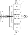
Fig. 1 is a plan schematic diagram of an embodiment of a powerplant arrangement in accordance with this disclosure; -
Fig. 2 is a plan schematic view of an embodiment of an aircraft in accordance with this disclosure; an -
Fig. 3 is a diagram showing an embodiment of a power control scheme relative to flight phase (e.g., altitude) in accordance with this disclosure. - Reference will now be made to the drawings wherein like reference numerals identify similar structural features or aspects of the subject disclosure. For purposes of explanation and illustration, and not limitation, an illustrative view of an embodiment of an arrangement in accordance with the disclosure is shown in
Fig. 1 and is designated generally byreference character 100. Other embodiments and/or aspects of this disclosure are shown inFigs. 2 and3 . - Referring to
Figs. 1 and2 , a hybrid electricaircraft powerplant arrangement 100 can include afirst wing pair 101a of powerplants for a first wing (e.g., wing 201) of an aircraft (e.g., aircraft 200). Thefirst wing pair 101a can include a firstelectric powerplant 103a configured to drive afirst air mover 105a and a firstheat engine powerplant 107a configured to drive asecond air mover 105b separate from thefirst air mover 105a. Any number of wing pairs on each wing of an aircraft is contemplated herein. - The
arrangement 100 can include asecond wing pair 101b of powerplants for a second wing (e.g., wing 203) of the aircraft (e.g., aircraft 200). thesecond wing pair 101b can include a secondelectric powerplant 103b configured to drive athird air mover 105c separate from the first andsecond air movers heat engine powerplant 107b configured to drive afourth air mover 105d separate from the first, second, andthird air movers wing pair 101a and an additional heat engine or electric motor, two wing pairs on each wing, a plurality of wing pairs divided between the wings). - The first and second
electric powerplant heat engine powerplants arrangement 100 can include any other suitable components, e.g., one or more liquid fuel storages (e.g., connected together in any suitable manner) and fuel systems (e.g., controlled by a common controller, e.g., as described below) for heat engine fuel and/or one or more electrical energy storages for powering the electric powerplants). - As shown, the first
electric powerplant 103a can be inboard (e.g., closer to the centerline of the aircraft) of the firstheat engine powerplant 107a. The secondelectric powerplant 103b can also be inboard of the secondheat engine powerplant 107b. This can lower torque in the event of a heat engine failure, reducing the amount of needed compensatory control, for example. However, certain embodiments can have one or more of theelectric powerplants heat powerplants - The
arrangement 100 can include acommon controller 109 configured to operate each of thepowerplants powerplant common controller 109, for example. However, it is contemplated that only thecommon controller 109 can be connected to each powerplant system directly as needed. Thecommon controller 109 can include any suitable hardware and/or software configured to perform any function disclosed herein. - In certain embodiments, referring additionally to
Fig. 3 , the firstheat engine powerplant 107a and the secondheat engine powerplant 107b can be sized to provide full power from take-off through cruise until descent. In certain embodiments, thecommon controller 109 can be configured to control the firstheat engine powerplant 107a and the secondheat engine powerplant 107b to operate at only full power, idle power, and a single power setting (e.g., a lower power descent setting, e.g., about 20% power) between full power and idle power, for example, e.g., as shown inFig. 3 . Any other suitable number of power settings (e.g., a variety of discrete power settings) between full power and idle power is contemplated herein. - The
arrangement 100 can further include the first, second, third, andfourth air movers 105a, b, c, d. Each of theair movers 105a, b, c, d can be a propeller, for example. Any other type of air mover is contemplated herein (e.g., a fan or any other similar device). - In certain embodiments, the first
electric powerplant 103a and the secondelectric powerplant 103b can be powered by one or moreelectrical energy sources heat engine powerplants heat engine powerplant 107a and/or the secondheat engine powerplant 107b can be configured to provide electrical energy to the one or moreelectrical energy sources - In accordance with this disclosure, a hybrid
electric aircraft 200 can include afirst wing 201 and a second wing 203 (e.g., attached to a fuselage). Theaircraft 200 can include afirst wing pair 101a of powerplants, e.g., as described above, attached to thefirst wing 201, and asecond wing pair 101b of powerplants, e.g., as described above, attached to thesecond wing 203 of theaircraft 200. Theaircraft 200 can include any other suitable components. - Certain embodiments can include four 1000 HP powerplants instead of two 2000 HP powerplants on other twin engine types of aircraft, for example. Any suitable maximum production by each power plant (e.g., the same or different from each other) is contemplated herein. Certain embodiments provide a parallel hybrid architecture having distributed fuel burning engines and electric motors, each driving dedicated propellers. Embodiments include separate powertrains with separate propellers. As disclosed above, embodiments can include two electric powerplants and two heat engine powerplants symmetrically disposed on an aircraft. Embodiments of electric and heat powerplants may only be connected by a common controller configured to divide power between heat engine power and electric power.
- In certain embodiments, heat engine powerplants can be operated continuously at full power throughout the flight, while the electric powerplants would be operated as needed to provide supplemental power (e.g., during takeoff and climb operations).
- Embodiments can provide improved fuel economy due to implementation of two optimally sized fuel burning engines to support cruise instead of four gas turbines running at non-optimum conditions. Embodiments can include reasonable battery sizing due to targeted usage of electric powertrain relative to total mission length. Embodiments can be retrofit into existing aircraft configurations.
- Those having ordinary skill in the art understand that any numerical values disclosed herein can be exact values or can be values within a range. Further, any terms of approximation (e.g., "about", "approximately", "around") used in this disclosure can mean the stated value within a range. For example, in certain embodiments, the range can be within (plus or minus) 20%, or within 10%, or within 5%, or within 2%, or within any other suitable percentage or number as appreciated by those having ordinary skill in the art (e.g., for known tolerance limits or error ranges).
- The articles "a", "an", and "the" as used herein and in the appended claims are used herein to refer to one or to more than one (i.e., to at least one) of the grammatical object of the article unless the context clearly indicates otherwise. By way of example, "an element" means one element or more than one element.
- The phrase "and/or," as used herein in the specification and in the claims, should be understood to mean "either or both" of the elements so conjoined, i.e., elements that are conjunctively present in some cases and disjunctively present in other cases. Multiple elements listed with "and/or" should be construed in the same fashion, i.e., "one or more" of the elements so conjoined. Other elements may optionally be present other than the elements specifically identified by the "and/or" clause, whether related or unrelated to those elements specifically identified. Thus, as a non-limiting example, a reference to "A and/or B", when used in conjunction with open-ended language such as "comprising" can refer, in one embodiment, to A only (optionally including elements other than B); in another embodiment, to B only (optionally including elements other than A); in yet another embodiment, to both A and B (optionally including other elements); etc.
- As used herein in the specification and in the claims, "or" should be understood to have the same meaning as "and/or" as defined above. For example, when separating items in a list, "or" or "and/or" shall be interpreted as being inclusive, i.e., the inclusion of at least one, but also including more than one, of a number or list of elements, and, optionally, additional unlisted items. Only terms clearly indicated to the contrary, such as "only one of' or "exactly one of," or, when used in the claims, "consisting of," will refer to the inclusion of exactly one element of a number or list of elements. In general, the term "or" as used herein shall only be interpreted as indicating exclusive alternatives (i.e., "one or the other but not both") when preceded by terms of exclusivity, such as "either," "one of," "only one of," or "exactly one of."
- Any suitable combination(s) of any disclosed embodiments and/or any suitable portion(s) thereof are contemplated herein as appreciated by those having ordinary skill in the art in view of this disclosure.
- The embodiments of the present disclosure, as described above and shown in the drawings, provide for improvement in the art to which they pertain. While the subject disclosure includes reference to certain embodiments, those skilled in the art will readily appreciate that changes and/or modifications may be made thereto without departing from the spirit and scope of the subject disclosure.
Claims (11)
- A hybrid electric aircraft powerplant arrangement (100) comprising:a first wing pair of powerplants (101a) for a first wing (201) of an aircraft (200), the first wing pair of powerplants (101a) comprising a first electric powerplant (103a) configured to drive a first air mover (105a) and a first heat engine powerplant (107a) configured to drive a second air mover (105b) separate from the first air mover (105a); anda second wing pair of powerplants (101b) for a second wing (203) of the aircraft (200), the second wing pair of powerplants (101b) comprising a second electric powerplant (103b) configured to drive a third air mover (105c) separate from the first and second air movers (105a, 105b), and a second heat engine powerplant (107b) configured to drive a fourth air mover (105d) separate from the first, second, and third air movers (105a, 105b, 105c).
- The arrangement (100) of claim 1, wherein the first electric powerplant (103a) is inboard of the first heat engine powerplant (107a).
- The arrangement (100) of claim 1 or 2, wherein the second electric powerplant (103b) is inboard of the second heat engine powerplant (107b).
- The arrangement (100) of any preceding claim, further comprising a common controller (109) configured to operate each of the powerplants (103a, 103b, 107a, 107b).
- The arrangement (100) of claim 4, wherein the common controller (109) is configured to control the first heat engine powerplant (107a) and the second heat engine powerplant (107b) to operate at only full power, idle power, and a single power setting between full power and idle power.
- The arrangement (100) of any preceding claim, wherein the first heat engine powerplant (107a) and the second heat engine powerplant (107b) are sized to provide full power from take-off through cruise until descent.
- The arrangement (100) of any preceding claim, further comprising the first, second, third, and fourth air movers (105a, 105b, 105c, 105d).
- The arrangement (100) of claim 7, wherein each of the air movers (105a, 105b, 105c, 105d) is a propeller or fan.
- The arrangement (100) of any preceding claim, wherein the first electric powerplant (103a) and the second electric powerplant (103b) are powered by one or more electrical energy sources (111a, 111b) that is separate from the first and second heat engine powerplants (107a, 107b).
- The arrangement (100) of claim 9, wherein the first heat engine powerplant (107a) and/or the second heat engine powerplant (107b) are configured to provide electrical energy to the one or more electrical energy sources (111a, 111b).
- A hybrid electric aircraft (200) comprising:the arrangement (100) of any preceding claim;a first wing (201); anda second wing (203), wherein the first wing pair of powerplants (101a) is attached to the first wing (201), and the second wing pair of powerplants (101b) is attached to the second wing (203).
Applications Claiming Priority (2)
| Application Number | Priority Date | Filing Date | Title |
|---|---|---|---|
| US201962891827P | 2019-08-26 | 2019-08-26 | |
| US16/998,881 US11912422B2 (en) | 2019-08-26 | 2020-08-20 | Hybrid electric aircraft and powerplant arrangements |
Publications (2)
| Publication Number | Publication Date |
|---|---|
| EP3786068A1 true EP3786068A1 (en) | 2021-03-03 |
| EP3786068B1 EP3786068B1 (en) | 2025-11-05 |
Family
ID=72266140
Family Applications (1)
| Application Number | Title | Priority Date | Filing Date |
|---|---|---|---|
| EP20192971.8A Active EP3786068B1 (en) | 2019-08-26 | 2020-08-26 | Hybrid electric aircraft and powerplant arrangements |
Country Status (2)
| Country | Link |
|---|---|
| US (1) | US11912422B2 (en) |
| EP (1) | EP3786068B1 (en) |
Cited By (1)
| Publication number | Priority date | Publication date | Assignee | Title |
|---|---|---|---|---|
| US20210261260A1 (en) * | 2020-02-21 | 2021-08-26 | Valery Miftakhov | Modular electric powertrain conversion for aircraft |
Families Citing this family (3)
| Publication number | Priority date | Publication date | Assignee | Title |
|---|---|---|---|---|
| US12145738B2 (en) * | 2022-08-22 | 2024-11-19 | Pratt & Whitney Canada Corp. | Multi-drive unit propulsion system for an aircraft |
| US12503241B2 (en) | 2024-04-23 | 2025-12-23 | Rtx Corporation | Thermal management assembly for an aircraft propulsion system |
| SE548174C2 (en) * | 2024-10-07 | 2026-04-13 | Heart Aerospace AB | A hybrid-electric propulsion system for an aircraft and a control system for a hybrid electric propulsion system |
Citations (3)
| Publication number | Priority date | Publication date | Assignee | Title |
|---|---|---|---|---|
| US20160355272A1 (en) * | 2015-05-13 | 2016-12-08 | Rolls-Royce Plc | Aircraft propulsion system |
| US20180044028A1 (en) * | 2015-02-27 | 2018-02-15 | Mitsubishi Heavy Industries, Ltd. | Thrust force generation device and aircraft |
| US20180362169A1 (en) * | 2017-06-16 | 2018-12-20 | Xing Du | Aircraft with electric and fuel engines |
Family Cites Families (38)
| Publication number | Priority date | Publication date | Assignee | Title |
|---|---|---|---|---|
| JP2002112593A (en) | 2000-09-27 | 2002-04-12 | Hideo Kawamura | Power generator with multiple power generation characteristics |
| DE102004020122B4 (en) | 2004-04-24 | 2007-06-06 | Diehl Aerospace Gmbh | LED tubes hybrid lighting device |
| JP4092728B2 (en) * | 2005-01-25 | 2008-05-28 | 独立行政法人 宇宙航空研究開発機構 | Aircraft propulsion system |
| US20080017426A1 (en) | 2006-03-23 | 2008-01-24 | Walters Raul J | Modular vehicle system and method |
| US20080078876A1 (en) | 2006-08-15 | 2008-04-03 | Baggette Phillip D | Composite resin window frame constructions for airplanes |
| US7984684B2 (en) | 2006-10-06 | 2011-07-26 | Mitja Victor Hinderks | Marine hulls and drives |
| US7937945B2 (en) | 2006-10-27 | 2011-05-10 | Kinde Sr Ronald August | Combining a series of more efficient engines into a unit, or modular units |
| US8267347B2 (en) | 2007-01-22 | 2012-09-18 | Yan Goldshteyn | Winging car |
| US20120227389A1 (en) | 2008-04-16 | 2012-09-13 | Hinderks M V | Reciprocating machine & other devices |
| WO2010123601A1 (en) | 2009-01-27 | 2010-10-28 | Kuhn Ira F Jr | Purebred and hybrid electric vtol tilt rotor aircraft |
| EP2289797B1 (en) | 2009-08-27 | 2011-11-02 | Eurocopter Deutschland GmbH | A retractable undercarriage for a rotary wing aircraft |
| US20120111994A1 (en) | 2010-01-15 | 2012-05-10 | Propulsive Wing, LLC | Cross-flow fan propulsion system |
| EP2595882B1 (en) | 2010-07-19 | 2016-06-08 | Zee.Aero Inc. | Personal aircraft |
| US8532961B2 (en) | 2010-10-29 | 2013-09-10 | The Boeing Company | Method and system to account for angle of attack effects in engine noise shielding tests |
| TWI538852B (en) | 2011-07-19 | 2016-06-21 | 季航空股份有限公司 | Personal aircraft |
| US8827200B2 (en) | 2011-09-16 | 2014-09-09 | Bogdan Radu | Flying vehicle |
| GB201117692D0 (en) * | 2011-10-13 | 2011-11-23 | Rolls Royce Plc | A distributed propulsion system and method of control |
| FR2984274B1 (en) | 2011-12-15 | 2014-06-27 | Airbus Operations Sas | SECURED BEAM, IN PARTICULAR A STRONG FUSELAGE FRAME, AS WELL AS AIRCRAFT FUSELAGE EQUIPPED WITH SUCH FRAMES |
| CA2820254C (en) | 2012-07-09 | 2020-02-18 | Mcmaster University | Hybrid powertrain system |
| US20150321752A1 (en) | 2012-11-28 | 2015-11-12 | Michael W. Trull | Vibration damping devices, systems, and methods for aircraft |
| FR3000195B1 (en) | 2012-12-21 | 2019-08-09 | Airbus Operations | HYBRID ARCHITECTURE FOR AERONAUTICAL SYSTEM |
| DE102013020601B4 (en) | 2013-12-11 | 2018-03-22 | Airbus Defence and Space GmbH | aircraft configuration |
| US20150210407A1 (en) | 2014-01-28 | 2015-07-30 | Northrop Grumman Systems Corporation | Lifting entry/atmospheric flight (leaf) unified platform for ultra-low ballistic coefficient atmospheric entry and maneuverable atmospheric flight at solar system bodies |
| US10287000B2 (en) | 2014-07-25 | 2019-05-14 | Hyalta Aeronautics, Inc. | Hybrid lighter-than-air vehicle |
| US9994313B2 (en) | 2014-11-26 | 2018-06-12 | XCraft Enterprises, LLC | High speed multi-rotor vertical takeoff and landing aircraft |
| US20160272310A1 (en) | 2014-12-04 | 2016-09-22 | Elwha Llc | Reconfigurable unmanned aircraft system |
| US9919797B2 (en) | 2014-12-04 | 2018-03-20 | Elwha Llc | System and method for operation and management of reconfigurable unmanned aircraft |
| EP3657905B1 (en) | 2015-01-06 | 2022-09-21 | Battelle Memorial Institute | Uniform heat distribution in resistive heaters for anti-icing and de-icing |
| US9896197B2 (en) | 2015-05-28 | 2018-02-20 | Eugene H Vetter | Devices and methods for in flight transition VTOL/fixed wing hybrid aircraft structures and flight modes |
| US10308365B2 (en) | 2015-10-12 | 2019-06-04 | Codrin-Gruie (CG) Cantemir | Fully integrated hybrid electric jet engine |
| CA2958375C (en) | 2016-05-06 | 2025-01-07 | Rolls-Royce North American Technologies, Inc. | OPTIONALLY HYBRID POWER SYSTEM |
| US10676183B2 (en) | 2016-05-13 | 2020-06-09 | Bell Helicopter Textron Inc. | Forward folding rotor blades |
| US20170341725A1 (en) | 2016-05-29 | 2017-11-30 | Edward Francis Skahan | Motor-wing Gimbal Aircraft, Methods, and Applications |
| US10494117B2 (en) | 2017-08-14 | 2019-12-03 | Marinus Bernard Bosma | Parallel hybrid-electric aircraft engine |
| US11208207B2 (en) | 2016-10-31 | 2021-12-28 | Textron Innovations Inc. | Vertical takeoff and landing (VTOL) aircraft |
| US20180141655A1 (en) | 2016-11-23 | 2018-05-24 | Keith Wall | VTOL airplane or drone utilizing at least two tilting propellers located in front of wings center of gravity. |
| US10793281B2 (en) * | 2017-02-10 | 2020-10-06 | General Electric Company | Propulsion system for an aircraft |
| US10145291B1 (en) | 2017-10-10 | 2018-12-04 | Pratt & Whitney Canada Corp. | Rotary engine and method of combusting fuel |
-
2020
- 2020-08-20 US US16/998,881 patent/US11912422B2/en active Active
- 2020-08-26 EP EP20192971.8A patent/EP3786068B1/en active Active
Patent Citations (3)
| Publication number | Priority date | Publication date | Assignee | Title |
|---|---|---|---|---|
| US20180044028A1 (en) * | 2015-02-27 | 2018-02-15 | Mitsubishi Heavy Industries, Ltd. | Thrust force generation device and aircraft |
| US20160355272A1 (en) * | 2015-05-13 | 2016-12-08 | Rolls-Royce Plc | Aircraft propulsion system |
| US20180362169A1 (en) * | 2017-06-16 | 2018-12-20 | Xing Du | Aircraft with electric and fuel engines |
Cited By (2)
| Publication number | Priority date | Publication date | Assignee | Title |
|---|---|---|---|---|
| US20210261260A1 (en) * | 2020-02-21 | 2021-08-26 | Valery Miftakhov | Modular electric powertrain conversion for aircraft |
| US11577846B2 (en) * | 2020-02-21 | 2023-02-14 | ZeroAvia, Inc. | Modular electric powertrain conversion for aircraft |
Also Published As
| Publication number | Publication date |
|---|---|
| US11912422B2 (en) | 2024-02-27 |
| EP3786068B1 (en) | 2025-11-05 |
| US20210061481A1 (en) | 2021-03-04 |
Similar Documents
| Publication | Publication Date | Title |
|---|---|---|
| US12391391B2 (en) | Propulsion system and methods of use thereof | |
| EP3786068B1 (en) | Hybrid electric aircraft and powerplant arrangements | |
| US9764848B1 (en) | Propulsion system for an aircraft | |
| US20160355272A1 (en) | Aircraft propulsion system | |
| US12006052B2 (en) | Electrical power system for a vehicle | |
| US12510020B2 (en) | Hybrid-electric propulsion system equipped with a coupler for switching between modes of operation | |
| KR20110083656A (en) | Hybrid propulsion engine with at least one independently rotatable propeller / fan | |
| US20230138513A1 (en) | Twin propulsor, parallel hybrid, streamlined nacelle propulsion system | |
| EP4188803A1 (en) | Hybrid-electric drive system for multi-engine aircraft | |
| EP3931091B1 (en) | Distributed propulsion configurations for aircraft having mixed drive systems | |
| EP3931090A1 (en) | Aircraft propulsion system having hybrid-electric powerplant and combustion powerplant | |
| EP4477546A1 (en) | Aircraft air system with dedicated compressor(s) | |
| US20250242930A1 (en) | Aeronautical power system | |
| EP4463377A1 (en) | Hybrid aircraft propulsion |
Legal Events
| Date | Code | Title | Description |
|---|---|---|---|
| PUAI | Public reference made under article 153(3) epc to a published international application that has entered the european phase |
Free format text: ORIGINAL CODE: 0009012 |
|
| STAA | Information on the status of an ep patent application or granted ep patent |
Free format text: STATUS: THE APPLICATION HAS BEEN PUBLISHED |
|
| AK | Designated contracting states |
Kind code of ref document: A1 Designated state(s): AL AT BE BG CH CY CZ DE DK EE ES FI FR GB GR HR HU IE IS IT LI LT LU LV MC MK MT NL NO PL PT RO RS SE SI SK SM TR |
|
| AX | Request for extension of the european patent |
Extension state: BA ME |
|
| STAA | Information on the status of an ep patent application or granted ep patent |
Free format text: STATUS: REQUEST FOR EXAMINATION WAS MADE |
|
| 17P | Request for examination filed |
Effective date: 20210903 |
|
| RBV | Designated contracting states (corrected) |
Designated state(s): AL AT BE BG CH CY CZ DE DK EE ES FI FR GB GR HR HU IE IS IT LI LT LU LV MC MK MT NL NO PL PT RO RS SE SI SK SM TR |
|
| STAA | Information on the status of an ep patent application or granted ep patent |
Free format text: STATUS: EXAMINATION IS IN PROGRESS |
|
| 17Q | First examination report despatched |
Effective date: 20220628 |
|
| REG | Reference to a national code |
Ref country code: DE Ref legal event code: R079 Free format text: PREVIOUS MAIN CLASS: B64D0027020000 Ipc: B64D0031020000 Ref country code: DE Ref legal event code: R079 Ref document number: 602020061556 Country of ref document: DE Free format text: PREVIOUS MAIN CLASS: B64D0027020000 Ipc: B64D0031020000 |
|
| GRAP | Despatch of communication of intention to grant a patent |
Free format text: ORIGINAL CODE: EPIDOSNIGR1 |
|
| STAA | Information on the status of an ep patent application or granted ep patent |
Free format text: STATUS: GRANT OF PATENT IS INTENDED |
|
| RIC1 | Information provided on ipc code assigned before grant |
Ipc: B64D 35/025 20250101ALI20250520BHEP Ipc: B64D 31/18 20240101ALI20250520BHEP Ipc: B64D 27/33 20240101ALI20250520BHEP Ipc: B64D 27/31 20240101ALI20250520BHEP Ipc: B64D 31/02 20060101AFI20250520BHEP |
|
| INTG | Intention to grant announced |
Effective date: 20250530 |
|
| GRAS | Grant fee paid |
Free format text: ORIGINAL CODE: EPIDOSNIGR3 |
|
| GRAA | (expected) grant |
Free format text: ORIGINAL CODE: 0009210 |
|
| STAA | Information on the status of an ep patent application or granted ep patent |
Free format text: STATUS: THE PATENT HAS BEEN GRANTED |
|
| AK | Designated contracting states |
Kind code of ref document: B1 Designated state(s): AL AT BE BG CH CY CZ DE DK EE ES FI FR GB GR HR HU IE IS IT LI LT LU LV MC MK MT NL NO PL PT RO RS SE SI SK SM TR |
|
| REG | Reference to a national code |
Ref country code: CH Ref legal event code: F10 Free format text: ST27 STATUS EVENT CODE: U-0-0-F10-F00 (AS PROVIDED BY THE NATIONAL OFFICE) Effective date: 20251105 Ref country code: GB Ref legal event code: FG4D |
|
| REG | Reference to a national code |
Ref country code: DE Ref legal event code: R096 Ref document number: 602020061556 Country of ref document: DE |
|
| REG | Reference to a national code |
Ref country code: IE Ref legal event code: FG4D |
|
| REG | Reference to a national code |
Ref country code: NL Ref legal event code: MP Effective date: 20251105 |
|
| PG25 | Lapsed in a contracting state [announced via postgrant information from national office to epo] |
Ref country code: ES Free format text: LAPSE BECAUSE OF FAILURE TO SUBMIT A TRANSLATION OF THE DESCRIPTION OR TO PAY THE FEE WITHIN THE PRESCRIBED TIME-LIMIT Effective date: 20251105 |
|
| REG | Reference to a national code |
Ref country code: LT Ref legal event code: MG9D |
|
| PG25 | Lapsed in a contracting state [announced via postgrant information from national office to epo] |
Ref country code: NO Free format text: LAPSE BECAUSE OF FAILURE TO SUBMIT A TRANSLATION OF THE DESCRIPTION OR TO PAY THE FEE WITHIN THE PRESCRIBED TIME-LIMIT Effective date: 20260205 |
|
| PG25 | Lapsed in a contracting state [announced via postgrant information from national office to epo] |
Ref country code: AT Free format text: LAPSE BECAUSE OF FAILURE TO SUBMIT A TRANSLATION OF THE DESCRIPTION OR TO PAY THE FEE WITHIN THE PRESCRIBED TIME-LIMIT Effective date: 20251105 Ref country code: FI Free format text: LAPSE BECAUSE OF FAILURE TO SUBMIT A TRANSLATION OF THE DESCRIPTION OR TO PAY THE FEE WITHIN THE PRESCRIBED TIME-LIMIT Effective date: 20251105 Ref country code: HR Free format text: LAPSE BECAUSE OF FAILURE TO SUBMIT A TRANSLATION OF THE DESCRIPTION OR TO PAY THE FEE WITHIN THE PRESCRIBED TIME-LIMIT Effective date: 20251105 |
|
| REG | Reference to a national code |
Ref country code: AT Ref legal event code: MK05 Ref document number: 1854124 Country of ref document: AT Kind code of ref document: T Effective date: 20251105 |
|
| PG25 | Lapsed in a contracting state [announced via postgrant information from national office to epo] |
Ref country code: NL Free format text: LAPSE BECAUSE OF FAILURE TO SUBMIT A TRANSLATION OF THE DESCRIPTION OR TO PAY THE FEE WITHIN THE PRESCRIBED TIME-LIMIT Effective date: 20251105 |
|
| PG25 | Lapsed in a contracting state [announced via postgrant information from national office to epo] |
Ref country code: RS Free format text: LAPSE BECAUSE OF FAILURE TO SUBMIT A TRANSLATION OF THE DESCRIPTION OR TO PAY THE FEE WITHIN THE PRESCRIBED TIME-LIMIT Effective date: 20260205 |
|
| PG25 | Lapsed in a contracting state [announced via postgrant information from national office to epo] |
Ref country code: IS Free format text: LAPSE BECAUSE OF FAILURE TO SUBMIT A TRANSLATION OF THE DESCRIPTION OR TO PAY THE FEE WITHIN THE PRESCRIBED TIME-LIMIT Effective date: 20260305 |
|
| PG25 | Lapsed in a contracting state [announced via postgrant information from national office to epo] |
Ref country code: PT Free format text: LAPSE BECAUSE OF FAILURE TO SUBMIT A TRANSLATION OF THE DESCRIPTION OR TO PAY THE FEE WITHIN THE PRESCRIBED TIME-LIMIT Effective date: 20260305 |
|
| PG25 | Lapsed in a contracting state [announced via postgrant information from national office to epo] |
Ref country code: PL Free format text: LAPSE BECAUSE OF FAILURE TO SUBMIT A TRANSLATION OF THE DESCRIPTION OR TO PAY THE FEE WITHIN THE PRESCRIBED TIME-LIMIT Effective date: 20251105 |
|
| PG25 | Lapsed in a contracting state [announced via postgrant information from national office to epo] |
Ref country code: LV Free format text: LAPSE BECAUSE OF FAILURE TO SUBMIT A TRANSLATION OF THE DESCRIPTION OR TO PAY THE FEE WITHIN THE PRESCRIBED TIME-LIMIT Effective date: 20251105 |
|
| PG25 | Lapsed in a contracting state [announced via postgrant information from national office to epo] |
Ref country code: BG Free format text: LAPSE BECAUSE OF FAILURE TO SUBMIT A TRANSLATION OF THE DESCRIPTION OR TO PAY THE FEE WITHIN THE PRESCRIBED TIME-LIMIT Effective date: 20251105 |
|
| PG25 | Lapsed in a contracting state [announced via postgrant information from national office to epo] |
Ref country code: LT Free format text: LAPSE BECAUSE OF FAILURE TO SUBMIT A TRANSLATION OF THE DESCRIPTION OR TO PAY THE FEE WITHIN THE PRESCRIBED TIME-LIMIT Effective date: 20251105 |
|
| PG25 | Lapsed in a contracting state [announced via postgrant information from national office to epo] |
Ref country code: SM Free format text: LAPSE BECAUSE OF FAILURE TO SUBMIT A TRANSLATION OF THE DESCRIPTION OR TO PAY THE FEE WITHIN THE PRESCRIBED TIME-LIMIT Effective date: 20251105 |
|
| PG25 | Lapsed in a contracting state [announced via postgrant information from national office to epo] |
Ref country code: DK Free format text: LAPSE BECAUSE OF FAILURE TO SUBMIT A TRANSLATION OF THE DESCRIPTION OR TO PAY THE FEE WITHIN THE PRESCRIBED TIME-LIMIT Effective date: 20251105 |
|
| PG25 | Lapsed in a contracting state [announced via postgrant information from national office to epo] |
Ref country code: IT Free format text: LAPSE BECAUSE OF FAILURE TO SUBMIT A TRANSLATION OF THE DESCRIPTION OR TO PAY THE FEE WITHIN THE PRESCRIBED TIME-LIMIT Effective date: 20251105 |
|
| PG25 | Lapsed in a contracting state [announced via postgrant information from national office to epo] |
Ref country code: EE Free format text: LAPSE BECAUSE OF FAILURE TO SUBMIT A TRANSLATION OF THE DESCRIPTION OR TO PAY THE FEE WITHIN THE PRESCRIBED TIME-LIMIT Effective date: 20251105 |
|
| PG25 | Lapsed in a contracting state [announced via postgrant information from national office to epo] |
Ref country code: CZ Free format text: LAPSE BECAUSE OF FAILURE TO SUBMIT A TRANSLATION OF THE DESCRIPTION OR TO PAY THE FEE WITHIN THE PRESCRIBED TIME-LIMIT Effective date: 20251105 |
|
| PG25 | Lapsed in a contracting state [announced via postgrant information from national office to epo] |
Ref country code: SK Free format text: LAPSE BECAUSE OF FAILURE TO SUBMIT A TRANSLATION OF THE DESCRIPTION OR TO PAY THE FEE WITHIN THE PRESCRIBED TIME-LIMIT Effective date: 20251105 |
|
| PG25 | Lapsed in a contracting state [announced via postgrant information from national office to epo] |
Ref country code: SE Free format text: LAPSE BECAUSE OF FAILURE TO SUBMIT A TRANSLATION OF THE DESCRIPTION OR TO PAY THE FEE WITHIN THE PRESCRIBED TIME-LIMIT Effective date: 20251105 |