EP3786057A1 - Methods and systems for remote piloting a two-pilot aircraft for extended flights - Google Patents
Methods and systems for remote piloting a two-pilot aircraft for extended flights Download PDFInfo
- Publication number
- EP3786057A1 EP3786057A1 EP19215092.8A EP19215092A EP3786057A1 EP 3786057 A1 EP3786057 A1 EP 3786057A1 EP 19215092 A EP19215092 A EP 19215092A EP 3786057 A1 EP3786057 A1 EP 3786057A1
- Authority
- EP
- European Patent Office
- Prior art keywords
- onboard
- flight control
- remote
- pilot
- control system
- Prior art date
- Legal status (The legal status is an assumption and is not a legal conclusion. Google has not performed a legal analysis and makes no representation as to the accuracy of the status listed.)
- Granted
Links
Images

Classifications
-
- B—PERFORMING OPERATIONS; TRANSPORTING
- B64—AIRCRAFT; AVIATION; COSMONAUTICS
- B64D—EQUIPMENT FOR FITTING IN OR TO AIRCRAFT; FLIGHT SUITS; PARACHUTES; ARRANGEMENT OR MOUNTING OF POWER PLANTS OR PROPULSION TRANSMISSIONS IN AIRCRAFT
- B64D47/00—Equipment not otherwise provided for
-
- B—PERFORMING OPERATIONS; TRANSPORTING
- B64—AIRCRAFT; AVIATION; COSMONAUTICS
- B64C—AEROPLANES; HELICOPTERS
- B64C13/00—Control systems or transmitting systems for actuating flying-control surfaces, lift-increasing flaps, air brakes, or spoilers
-
- B—PERFORMING OPERATIONS; TRANSPORTING
- B60—VEHICLES IN GENERAL
- B60N—SEATS SPECIALLY ADAPTED FOR VEHICLES; VEHICLE PASSENGER ACCOMMODATION NOT OTHERWISE PROVIDED FOR
- B60N2/00—Seats specially adapted for vehicles; Arrangement or mounting of seats in vehicles
- B60N2/02—Seats specially adapted for vehicles; Arrangement or mounting of seats in vehicles the seat or part thereof being movable, e.g. adjustable
- B60N2/0224—Non-manual adjustments, e.g. with electrical operation
- B60N2/0244—Non-manual adjustments, e.g. with electrical operation with logic circuits
- B60N2/0272—Non-manual adjustments, e.g. with electrical operation with logic circuits using sensors or detectors for detecting the position of seat parts
-
- B—PERFORMING OPERATIONS; TRANSPORTING
- B64—AIRCRAFT; AVIATION; COSMONAUTICS
- B64D—EQUIPMENT FOR FITTING IN OR TO AIRCRAFT; FLIGHT SUITS; PARACHUTES; ARRANGEMENT OR MOUNTING OF POWER PLANTS OR PROPULSION TRANSMISSIONS IN AIRCRAFT
- B64D11/00—Passenger or crew accommodation; Flight-deck installations not otherwise provided for
- B64D11/06—Arrangements of seats, or adaptations or details specially adapted for aircraft seats
- B64D11/0606—Arrangements of seats, or adaptations or details specially adapted for aircraft seats with privacy shells, screens, separators or the like
-
- B—PERFORMING OPERATIONS; TRANSPORTING
- B64—AIRCRAFT; AVIATION; COSMONAUTICS
- B64D—EQUIPMENT FOR FITTING IN OR TO AIRCRAFT; FLIGHT SUITS; PARACHUTES; ARRANGEMENT OR MOUNTING OF POWER PLANTS OR PROPULSION TRANSMISSIONS IN AIRCRAFT
- B64D11/00—Passenger or crew accommodation; Flight-deck installations not otherwise provided for
- B64D11/06—Arrangements of seats, or adaptations or details specially adapted for aircraft seats
- B64D11/0639—Arrangements of seats, or adaptations or details specially adapted for aircraft seats with features for adjustment or converting of seats
- B64D11/064—Adjustable inclination or position of seats
-
- B—PERFORMING OPERATIONS; TRANSPORTING
- B64—AIRCRAFT; AVIATION; COSMONAUTICS
- B64D—EQUIPMENT FOR FITTING IN OR TO AIRCRAFT; FLIGHT SUITS; PARACHUTES; ARRANGEMENT OR MOUNTING OF POWER PLANTS OR PROPULSION TRANSMISSIONS IN AIRCRAFT
- B64D11/00—Passenger or crew accommodation; Flight-deck installations not otherwise provided for
- B64D11/06—Arrangements of seats, or adaptations or details specially adapted for aircraft seats
- B64D11/0639—Arrangements of seats, or adaptations or details specially adapted for aircraft seats with features for adjustment or converting of seats
- B64D11/0641—Seats convertible into beds
-
- B—PERFORMING OPERATIONS; TRANSPORTING
- B64—AIRCRAFT; AVIATION; COSMONAUTICS
- B64D—EQUIPMENT FOR FITTING IN OR TO AIRCRAFT; FLIGHT SUITS; PARACHUTES; ARRANGEMENT OR MOUNTING OF POWER PLANTS OR PROPULSION TRANSMISSIONS IN AIRCRAFT
- B64D11/00—Passenger or crew accommodation; Flight-deck installations not otherwise provided for
- B64D11/06—Arrangements of seats, or adaptations or details specially adapted for aircraft seats
- B64D11/0639—Arrangements of seats, or adaptations or details specially adapted for aircraft seats with features for adjustment or converting of seats
- B64D11/0643—Adjustable foot or leg rests
-
- B—PERFORMING OPERATIONS; TRANSPORTING
- B64—AIRCRAFT; AVIATION; COSMONAUTICS
- B64D—EQUIPMENT FOR FITTING IN OR TO AIRCRAFT; FLIGHT SUITS; PARACHUTES; ARRANGEMENT OR MOUNTING OF POWER PLANTS OR PROPULSION TRANSMISSIONS IN AIRCRAFT
- B64D11/00—Passenger or crew accommodation; Flight-deck installations not otherwise provided for
- B64D11/06—Arrangements of seats, or adaptations or details specially adapted for aircraft seats
- B64D11/0689—Arrangements of seats, or adaptations or details specially adapted for aircraft seats specially adapted for pilots
-
- G—PHYSICS
- G05—CONTROLLING; REGULATING
- G05D—SYSTEMS FOR CONTROLLING OR REGULATING NON-ELECTRIC VARIABLES
- G05D1/00—Control of position, course, altitude or attitude of land, water, air or space vehicles, e.g. using automatic pilots
- G05D1/0011—Control of position, course, altitude or attitude of land, water, air or space vehicles, e.g. using automatic pilots associated with a remote control arrangement
-
- G—PHYSICS
- G05—CONTROLLING; REGULATING
- G05D—SYSTEMS FOR CONTROLLING OR REGULATING NON-ELECTRIC VARIABLES
- G05D1/00—Control of position, course, altitude or attitude of land, water, air or space vehicles, e.g. using automatic pilots
- G05D1/0011—Control of position, course, altitude or attitude of land, water, air or space vehicles, e.g. using automatic pilots associated with a remote control arrangement
- G05D1/0044—Control of position, course, altitude or attitude of land, water, air or space vehicles, e.g. using automatic pilots associated with a remote control arrangement by providing the operator with a computer generated representation of the environment of the vehicle, e.g. virtual reality, maps
-
- G—PHYSICS
- G05—CONTROLLING; REGULATING
- G05D—SYSTEMS FOR CONTROLLING OR REGULATING NON-ELECTRIC VARIABLES
- G05D1/00—Control of position, course, altitude or attitude of land, water, air or space vehicles, e.g. using automatic pilots
- G05D1/08—Control of attitude, i.e. control of roll, pitch, or yaw
- G05D1/0808—Control of attitude, i.e. control of roll, pitch, or yaw specially adapted for aircraft
-
- G—PHYSICS
- G07—CHECKING-DEVICES
- G07C—TIME OR ATTENDANCE REGISTERS; REGISTERING OR INDICATING THE WORKING OF MACHINES; GENERATING RANDOM NUMBERS; VOTING OR LOTTERY APPARATUS; ARRANGEMENTS, SYSTEMS OR APPARATUS FOR CHECKING NOT PROVIDED FOR ELSEWHERE
- G07C5/00—Registering or indicating the working of vehicles
- G07C5/008—Registering or indicating the working of vehicles communicating information to a remotely located station
-
- G—PHYSICS
- G08—SIGNALLING
- G08G—TRAFFIC CONTROL SYSTEMS
- G08G5/00—Traffic control systems for aircraft
- G08G5/20—Arrangements for acquiring, generating, sharing or displaying traffic information
- G08G5/26—Transmission of traffic-related information between aircraft and ground stations
-
- G—PHYSICS
- G08—SIGNALLING
- G08G—TRAFFIC CONTROL SYSTEMS
- G08G5/00—Traffic control systems for aircraft
- G08G5/50—Navigation or guidance aids
- G08G5/53—Navigation or guidance aids for cruising
-
- B—PERFORMING OPERATIONS; TRANSPORTING
- B64—AIRCRAFT; AVIATION; COSMONAUTICS
- B64D—EQUIPMENT FOR FITTING IN OR TO AIRCRAFT; FLIGHT SUITS; PARACHUTES; ARRANGEMENT OR MOUNTING OF POWER PLANTS OR PROPULSION TRANSMISSIONS IN AIRCRAFT
- B64D11/00—Passenger or crew accommodation; Flight-deck installations not otherwise provided for
- B64D2011/0069—Rest berths, beds or the like
- B64D2011/0076—Rest berths, beds or the like for crew members, e.g. for sleeping during flight
-
- B—PERFORMING OPERATIONS; TRANSPORTING
- B64—AIRCRAFT; AVIATION; COSMONAUTICS
- B64U—UNMANNED AERIAL VEHICLES [UAV]; EQUIPMENT THEREFOR
- B64U2201/00—UAVs characterised by their flight controls
- B64U2201/20—Remote controls
-
- G—PHYSICS
- G08—SIGNALLING
- G08G—TRAFFIC CONTROL SYSTEMS
- G08G5/00—Traffic control systems for aircraft
- G08G5/50—Navigation or guidance aids
- G08G5/55—Navigation or guidance aids for a single aircraft
Definitions
- Adding another onboard pilot to cover additional flight time would involve modifying the cockpit from a two-person layout. Where additional seats are already provided, they are typically smaller flip out seats located away from the flight controls and are smaller than full pilot seats or passenger seats and are not designed to be occupied for long periods of time.
- Additional flight crew members could be accommodated in the main cabin for inflight resting. However, this would reduce the space available for revenue service. Additionally, a third flight crew member would add cost and further reduce revenue.
- the present invention provides a system for both onboard piloting and remote piloting an aircraft having thereon at least one onboard pilot.
- the system includes an aircraft having an onboard first pilot seat, onboard sensors, onboard actuators, and an onboard flight control system, the onboard flight control system including onboard flight control devices and onboard condition indicators mounted proximal the first pilot seat.
- a remote flight control system is in electronic communication with the onboard flight control system by way of a two-way communication channel including at least one wireless segment.
- the remote flight control system includes remote flight control devices and remote condition indicators.
- the onboard flight control system is operative to receive condition-related inputs from the onboard sensors, to activate the onboard condition indicators according to the received condition-related inputs, and at least in an onboard piloting mode, to actuate the onboard actuators according to the onboard flight control devices, thereby onboard piloting the aircraft and at least in a remote piloting mode, transmit the condition-related signals to the remote flight control system, to receive flight control signals from the remote flight control system, and to actuate, according to the flight control signals received from the remote flight control system, the onboard actuators thereby remote piloting the aircraft.
- the first pilot seat is adjustable between an upright position and a reclined position, and the onboard flight control system is operative in the remote piloting mode upon the first pilot seat being adjusted to the reclined position.
- the aircraft further includes an onboard second pilot seat adjustable between an upright position and a reclined position.
- the onboard flight control system is operative in the remote piloting mode upon the second pilot seat being disposed in the reclined position.
- the first pilot seat is disposed in the reclined position thereof and the second pilot seat is disposed in the reclined position thereof at exclusive alternating times.
- the remote flight control system includes at least one display on which the remote condition indicators are graphically displayed.
- the aircraft further includes an onboard second pilot seat adjustable between an upright position and a reclined position, wherein the first pilot seat is adjustable between an upright position and a reclined position, and wherein the aircraft further includes a partition wall deployable between the first pilot seat and second pilot seat.
- the partition wall stows automatically as either of the first pilot seat and second pilot seat is adjusted from the reclined position thereof to the upright position thereof.
- the aircraft further includes an onboard second pilot seat, and, at least in the remote piloting mode, the remote pilot is simulated as placed into the aircraft by a virtual reality (VR) presentation viewable at the second pilot seat.
- VR virtual reality
- the aircraft further includes an onboard second pilot seat, and the remote piloting system is used to extend the range of the aircraft by permitting a first pilot in the first pilot seat and a second pilot in the second pilot seat to alternately rest as a third pilot at the remote flight control system pilots the aircraft cooperatively with the non-resting one of the first pilot and second pilot.
- the first pilot seat includes a seat position sensor in electronic communication with the onboard flight control system, and the onboard flight control system is operative to alert the remote flight control system when the onboard pilot seat is adjusted to a reclined position.
- the present invention disclosed herein provides an aircraft for both onboard piloting and remote piloting.
- the aircraft includes a system according to the first aspect of the present invention.
- the first pilot seat includes a backrest pivotally adjustable from an upright position to a fully reclined approximately horizontal position.
- the present invention may include one or more or any combination of the above aspects, features and configurations.
- an aircraft is remotely piloted, for example by a remote ground-based pilot.
- a remote pilot can assume a copilot role, as one of two onboard pilots rests, and the alert onboard pilot assumes a primary pilot role.
- a third pilot is able to fly the aircraft, from afar, in cooperation with the onboard crew, enabling onboard pilots to rest one at a time.
- the onboard pilot seats may be configured like premium class seating, such that the seats recline even to fully reclined or layback positions to attain true sleep. Such seats will achieve their fully reclined positions in a space similar to existing seats, thus requiring little cockpit redesign.
- an aircraft 10 having a two-pilot cockpit 12 is shown as having two pilot seats longitudinally aligned and spaced from each other, each on a respective side of a central longitudinal axis 14 of the aircraft.
- the pilot-accessible forward components of an onboard flight control system 20 are emphasized by dashed line.
- the flight control system 20 includes flight condition indicators 22 ( FIGS. 1 , 5 ), aircraft system condition indicators 24, and flight control devices for use by the pilots in controlling the aircraft.
- the flight control system includes an instrument panel 26 forward of the pilot seats, where many of the condition indicators and flight control devices are mounted to be readily accessible to pilots.
- the flight control system can have elements arranged and distributed elsewhere in the cockpit and aircraft.
- Redundancy in the flight instruments and controls of the system permit either pilot to control the aircraft.
- the first or left-side pilot seat 30 is typically assigned to a flight captain, and the second or right-side pilot seat 40 is typically assigned to a first officer.
- the roles the two onboard pilots assume may be exchanged and shared as they cooperatively control the aircraft.
- the first pilot seat 30 and second pilot seat 40 are referenced in the drawings and in the following descriptions without limitation imposed upon what role, for example as primary pilot or copilot, any pilot assumes in any seat at any time.
- a captain side joystick 32, a captain navigation bag 34, a first officer side joystick 42, and a first officer navigation bag 44, are accordingly assigned at the left and right sides of the pilot seating arrangement.
- a central pedestal 50, between the pilot seats, serves as a base on which actuatable thrust controllers and other onboard flight control devices 52 are accessible to, and shared by, the first pilot 36 and second pilot 46 ( FIG. 2 ).
- Flight control devices 52 are broadly considered in these descriptions to include the joysticks 32 and 42 and other devices that adjust the speed, orientation, trajectory of the aircraft and other parameters by which flight is adjusted and controlled.
- What additional seating is provided in the cockpit 12 may be of the cabin attendant seating (CAS) variety, meaning the third occupant seat 54 and fourth occupant seat 56 are smaller than the pilot seats, and do not, or only minimally, adjust and recline.
- the third occupant seat 54, aft or rearward of the pedestal 50 offers high visibility of the flight panel(s) 26 for observation.
- FIG. 2 a two-pilot cockpit 12 is shown during normal flight operation, in which an alert first pilot 36 occupies the first pilot seat 30, and an alert second pilot 46 occupies the second pilot seat 40.
- the aircraft 10 represented in FIG. 2 may be the same model as the aircraft represented in FIG. 1 , or another aircraft. Thus, the aircraft represented in FIG. 1 is a non-limiting example.
- the two pilots ( FIG. 2 ) cooperatively control the aircraft 10 in this mode.
- the distance and corresponding duration of the flight may exceed comfort or regulatory limits of the pilots, and rest may be needed accordingly.
- the maximum flight time for a pilot during a day is limited by regulation in some aeronautical jurisdictions, for example to nine hours, and eight hours at night. Flight duty period limits, accumulating both rest and alert times, can be higher, for example ranging from nine to fourteen hours, depending on how many segments are flown and the start time of the pilot's duty day.
- the pilot seats according to these descriptions may recline, for example through a range of reclined positions from their upright positions ( FIG. 2 ) for use by alert pilots to fully reclined or layback positions to attain true sleep, as illustrated for the first pilot seat 30 in FIG. 3 , in which the first pilot 36 is in a lying rest position.
- the backrest portion 37 of the seat 30 is pivotally lowered ( FIG. 4 ) from its upright position of FIG. 2
- the legrest portion 38 of the seat is pivotally raised in FIG. 4 from its forward reclined position of FIG. 2
- the seat bottom 39 may articulate with movements of the backrest to avoid binding or pinching.
- the backrests are pivotally lowered to horizontal positions, approximately aligned with the seat bottoms, and the legrests are pivotally raised.
- a partition wall 60 is shown in FIGS. 3 and 4 as deployed between the first pilot seat 30 and second pilot seat, providing a screened privacy are to the resting pilot.
- the partition wall 60 deploys manually or automatically as either pilot seat is reclined, for example to the fully reclined position.
- the partition wall 60 stows manually or automatically as either reclined pilot seat is returned to its upright position. In the stowed condition, the partition wall 60 is discretely stowed in a compact low-profile configuration or position.
- the partition wall 60 may be a thin rollable screen or sheet stowed on a spool or reel. Other wall constructions are within the scope of these descriptions.
- the flight crew member on the first pilot seat 30 may be resting to comply with maximum flight time limits set by aeronautical authorities, or airline operators or, the crew member may be resting by personal choice.
- the reclining pilot seats achieve their fully reclined positions in a space within the dimensions of the cockpit 12, and the partition wall 60 provides a perception of privacy to the resting occupant of the first pilot seat 30 while occupying very little space in both the deployed condition of FIGS. 3-4 and the stowed condition of FIG. 2 .
- FIG. 5 represents the aircraft 10 of FIGS. 2-4 in a more complete illustration to emphasize elements of the onboard flight control system components distributed through the fuselage 62 and wings 64.
- the aircraft includes onboard sensors 66, onboard actuators 68, and an onboard flight control system 20.
- the onboard sensors 66 can include, as non-limiting examples, flight condition sensors including air speed sensors, altitude sensors, temperature sensors, and other sensors that detect flight conditions outside and inside the aircraft 10.
- the onboard sensors 66 can also include aircraft system condition sensors including engine condition sensors, fuel level sensors, sensors that detect the status or condition of wing flaps and landing gear, and other sensors.
- the onboard actuators 68 can include, as non-limiting examples, actuators that adjust flight control surfaces such as the wing flaps, the vertical stabilizer rudder(s), and the horizontal stabilizer elevator(s).
- the onboard actuators 68 further include actuators by which the aircraft 10 is controlled in both flight and ground movement.
- the onboard actuators 68 can control the landing gear, and both ground and air braking systems.
- the onboard actuators 68 can also include devices that control engine speed and thrust.
- Actuators are broadly referenced to include mechanically, electrically, and fluidly driven devices and mechanisms.
- the onboard fight control system 70 is in operative communication with the onboard sensors 66 to receive condition-related inputs from the onboard sensors 66 and to activate the onboard condition indicators according to the received condition-related inputs.
- the onboard condition sensors accordingly include flight condition indicators 22 ( FIGS. 1 and 5 ) and aircraft system condition indicators 24 that respectively indicate flight and system conditions to the flight crew.
- the onboard flight control system 20 is in operative communication with the onboard actuators 68 to control and actuate the onboard actuators 68 according to the onboard flight control devices 52, thereby onboard piloting the aircraft. Dashed lines generally referenced in FIG.
- links 72 by which the onboard flight control system 20 is in operative communication with onboard sensors 66 and onboard actuators 68 are broadly considered to include electrical, mechanical, fluid, and optical links by which onboard sensors provide inputs to, and onboard actuators receive outputs from, the onboard flight control system 20.
- Onboard sensors 66, actuators 68, and links 72 therebetween, and the onboard flight control system 20, may have redundancies for assurance of flight control operations in the event one device or one system of redundant parallel devices and systems is inoperative or faulty.
- Piloting is generally conducted by at least one onboard pilot.
- the onboard flight control system 20 is operative to receive condition-related inputs from the onboard sensors 66, to activate the onboard condition indicators according to the received condition-related inputs, and, in an onboard piloting mode, to actuate the onboard actuators 68 according to the onboard flight control devices, thereby onboard piloting the aircraft 10.
- Control of the aircraft 10 is not necessarily exclusively executed by a single pilot of the two onboard pilots, who may cooperatively control the aircraft in the onboard piloting mode.
- a remote flight control system 80 is used to pilot the aircraft 10 cooperatively with at least one alert onboard pilot.
- the remote flight control system 80 is in electronic communication with the onboard flight control system 20 by way of a two-way communication channel including at least one wireless segment.
- the remote flight control system 80 is linked in a first two-way communication channel 90, by a ground-based first link 92, to a land-to-air transceiver 94, which conveys two-way communications 96 between the remote flight control system 80 and the aircraft 10 by way of a wireless segment 98 of the first two-way communication channel 90.
- a land-to-air transceiver 94 which conveys two-way communications 96 between the remote flight control system 80 and the aircraft 10 by way of a wireless segment 98 of the first two-way communication channel 90.
- the remote flight control system 80 is linked in a second two-way communication channel 100, by a ground-based second link 102, to a land-to-satellite transceiver 104, which conveys two-way communications 106 between the remote flight control system 80 and a communications satellite 110 by way of a wireless segment 108 of the second two-way communication channel 100.
- the communications satellite 110 further conveys the two-way communications to and from the aircraft by a wireless segment 112 of the second two-way communication channel 100.
- the onboard piloting system 70 transmits condition-related signals to the remote flight control system 80 and receives flight control signals from the remote flight control system.
- the remote flight control system 80 as illustrated includes displays 120 such as LED and/or LCD displays that on which the computer system 140 graphically displays the flight condition indicators and aircraft system condition indicators.
- the remote flight control system 80 includes input devices by which or according to which flight control signals are generated by the remote flight control system and transmitted to the onboard flight control system.
- the input devices can include, as non-limiting examples, a joystick 122, for example in the form of a mouse in some embodiments, one or more keyboards 124, and one or more touch screens.
- the remote flight control system 80 can include audio output and audio input devices by which the remote pilot can maintain audio communications, such as voice communications, with the aircraft onboard pilots and/or land-based flight controllers as represented by a flight control tower 130 in FIG. 6 .
- the remote flight control system 80 includes or displays flight condition indicators, aircraft system condition indicators, and flight control devices for use by a remote pilot in remotely piloting the aircraft.
- the remote flight control system 80 includes an instrument panel, as represented by the displays 120, where many of the condition indicators and flight control devices are mounted, or graphically represented, to be readily accessible to a remote pilot 136.
- the remote flight control system 80 in the illustrated non-limiting example, graphically displays flight condition indicators and aircraft system condition indicators that respectively indicate flight and system conditions as conveyed by the received condition-related signals. While other arrangements are within the scope of these descriptions, the remote flight control system 80 of FIG. 6 is generally computer-based, and accordingly includes a computer system 140 such as a workstation, server, or PC.
- the input devices serve as remote flight control devices by which the aircraft 10 is remotely piloted.
- the remote flight control system 80 may provide, to the remote pilot 136, any and all information available to onboard pilots.
- the remote pilot 136 is presented a simulated or remote cockpit and flying presentation.
- the remote third pilot can assume a piloting role, in particular serving as copilot in a non-limiting example.
- the remote pilot 136 may be simulated as placed into the cockpit 12 of the aircraft 10 by the use of respective virtual reality (VR) presentations within the cockpit and at the remote flight control system 80.
- the displays 120 at the remote flight control system 80 may display the onboard alert pilot to the remote pilot 136.
- the second pilot 46 may be displayed at the remote flight control system 80 as the first pilot 36 rests according to FIGS. 3-4 .
- displays at the onboard flight control system 20 and cockpit 12 may display the remote pilot 136 to the alert onboard pilot.
- VR headrest displays may be used at one or each location.
- each alert pilot, both onboard and remote may perceive the other pilot as present through VR presentation.
- the system 70 is provided for both onboard piloting and remote piloting an aircraft 10 having thereon at least one onboard pilot.
- the aircraft in a typical example will have two onboard pilot, one of which may rest at a time as an alert onboard pilot is assisted by the remote pilot via the remote flight control system 80.
- the onboard flight control system 20 is operative to receive condition-related inputs from the onboard sensors 66, to activate the onboard condition indicators according to the received condition-related inputs.
- the onboard flight control system 20 may have both an onboard piloting mode, in which onboard actuators are actuated according to the onboard flight control devices, thereby onboard piloting the aircraft, and a remote piloting mode. At least in the remote piloting mode, the onboard flight control system 20 transmits the condition-related signals from the onboard sensors 66 to the remote flight control system 80, and receives flight control signals from the remote flight control system 80. The onboard flight control system 20 may actuate, according to the flight control signals received from the remote flight control system 80, the onboard actuators 68 thereby remote piloting the aircraft 10.
- the remote piloting mode may be entered upon either the onboard first pilot seat 30 or second pilot seat 40 being adjusted to a fully reclined position, indicating that an onboard pilot is at rest.
- Each onboard pilot seat can include a respective seat position sensor 58 ( FIG. 4 ) in electronic communication with the onboard flight control system 20, with the onboard flight control system being operative to alert the remote flight control system 80 when the onboard pilot seat is adjusted to a reclined position.
- the onboard flight control system 20 may be automatically operative in the remote piloting mode upon either onboard pilot seat being adjusted to a reclined position, for example a fully reclined position.
- the first pilot seat 30 may be disposed in the reclined position thereof and the second pilot seat 40 may be disposed in the reclined position thereof at exclusive alternating times. Reclining both the first pilot seat 30 and the second pilot seat 40 may cause an alert action or alarm.
- the first pilot seat 30 and second pilot seat 40 may be prevented from reclining or fully reclining at once by interface and control of seat pivots using controlled adjusters or locks, for example by the onboard flight control system 20, or interlinked mechanisms of the seats.
- a third pilot 136 may pilot the aircraft 10 cooperatively with the non-resting one of the onboard first pilot 36 and second pilot 46.
- the onboard flight control system 20 may automatically return to the onboard piloting mode when both the onboard first pilot seat 30 and second pilot seat 40 are returned to their upright positions.
- reclining either onboard pilot seat may automatically switch the onboard flight control system 20 from the onboard piloting mode to the remote piloting mode, and returning the reclined onboard seat to its upright position may automatically switch the onboard flight control system to the onboard piloting mode.
- the onboard sensors 66 relay information, via the onboard flight control system 20 and one or more communication channels (90,100), to the computer system 140 of the remote flight control system 80, which has a processor where software is used to analyze the data received to confirm and indicate flight conditions and aircraft system conditions.
- the processor may be a component of a server, such as a digital computer also including input/output (I/O) interfaces, a network interface, a data store, and memory.
- the components may be communicatively coupled via a local interface such as one or more buses or other wired or wireless connections.
- the local interface may have additional elements such as controllers, buffers (caches), drivers, repeaters, and receivers, among others, to enable communications. Further, the local interface may include address, control, and/or data connections to enable appropriate communications among the components.
- the processor of the computing system 140 executes software instructions and may be any custom made or commercially available processor, a central processing unit (CPU), an auxiliary processor among several processors associated with the server, a semiconductor-based microprocessor (in the form of a microchip or chip set), or generally any device for executing software instructions.
- the processor is configured to execute software stored within the memory, to communicate data to and from the memory, and to generally control operations of the server pursuant to the software instructions.
- the I/O interfaces may be used to receive user input from and/or for providing system output to one or more devices or components such as the displays, an aircraft network as represented by the flight control tower 130 in FIG. 6 , and flight crew accessible devices.
- I/O interfaces may include a serial port, a parallel port, a small computer system interface (SCSI), a serial ATA (SATA), a fibre channel, Infiniband, iSCSI, a PCI Express interface (PCI-x), an infrared (IR) interface, a radio frequency (RF) interface, and/or a universal serial bus (USB) interface.
- SCSI small computer system interface
- SATA serial ATA
- PCI-x PCI Express interface
- IR infrared
- RF radio frequency
- USB universal serial bus
- a network interface may be used to enable the computer system 140 to communicate on a network, such as the Internet, a wide area network (WAN), a local area network (LAN) such as a secure aircraft network, and the like, etc.
- the network interface may include address, control, and/or data connections to enable appropriate communications on the network.
- a data store may be used to store data.
- the data store may include any of volatile memory elements (e.g., random access memory (RAM, such as DRAM, SRAM, SDRAM, and the like)), nonvolatile memory elements (e.g., ROM, hard drive, tape, CDROM, and the like), and combinations thereof.
- the data store may incorporate electronic, magnetic, optical, and/or other types of storage media.
- the data store may be located internal to the server such as, for example, an internal hard drive connected to the local interface in the server. Additionally, in another embodiment, the data store may be located external to the server such as, for example, an external hard drive connected to the I/O interfaces (e.g., SCSI or USB connection). In a further embodiment, the data store may be connected to the server through a network, such as, for example, a network attached file server.
- a network such as, for example, a network attached file server.
- the memory may include any of volatile memory elements (e.g., random access memory (RAM, such as DRAM, SRAM, SDRAM, etc.)), nonvolatile memory elements (e.g., ROM, hard drive, tape, CDROM, etc.), and combinations thereof. Moreover, the memory may incorporate electronic, magnetic, optical, and/or other types of storage media.
- the software in memory may include one or more software programs, each of which includes an ordered listing of executable instructions for implementing logical functions.
- the software in the memory includes a suitable operating system (O/S) and one or more programs.
- the operating system essentially controls the execution of other computer programs, such as the one or more programs, and provides scheduling, input-output control, file and data management, memory management, and communication control and related services.
- the one or more programs may be configured to implement the various processes, algorithms, methods, techniques, etc. described herein.
- military communication protocols may be used, such as protocols used to control an unmanned aerial vehicle (UAV), and channeled to the remote flight control system 80 and remote pilot 136.
- Communication protocols of the system for remotely piloting of the aircraft 10 with high security may be military grade while serving a civilian based aviation system.
- Remote flight control of the aircraft may be used to improve flight safety and security against incidents where smoke, low oxygen, or other health issues are problematic in the cockpit.
- Remote flight control of the aircraft 10 may be used in the event of a terrorist situation.
- EOPs Extended Twin Operations
- the system 70 can increase the effective range of long-range aircraft without major changes to cabin installations onboard.
- the system 70 can be used to relieve onboard flight crew members in compliance with maximum flight times for a pilot during a day according to aviation regulations or airline operator standards. This means that point to point airport pairs that were previously connected via non-directed routes can now be directly connected in a single flight. For example, Dallas Fort Worth and Frankfort airports can be directly connected, whereas only flights between the east coast of the US and restricted locations in Europe were previously made by commercial passenger airline operators.
Landscapes
- Engineering & Computer Science (AREA)
- Aviation & Aerospace Engineering (AREA)
- Physics & Mathematics (AREA)
- General Physics & Mathematics (AREA)
- Radar, Positioning & Navigation (AREA)
- Remote Sensing (AREA)
- Automation & Control Theory (AREA)
- General Engineering & Computer Science (AREA)
- Transportation (AREA)
- Mechanical Engineering (AREA)
- Selective Calling Equipment (AREA)
- Toys (AREA)
Abstract
Description
- The advent of current generation single-aisle aircraft that can fly further than 4,500 nautical miles, in a flight time of approximately 10.5 hours, raises the issue that flight crewmen can actively pilot an aircraft for time periods limited by country or airline operator standards. For example, two men can only legally fly for eight hours in the United States. Such aircraft are being developed as they are very cost effective in terms of cost per mile to operate. Thus, aircraft entering use are capable of exceeding regulations set by, for example, the Federal Aviation Administration (FAA) of the United States and other aviation authorities abroad that dictate flight time limitations for one or two pilot crews.
- Adding another onboard pilot to cover additional flight time would involve modifying the cockpit from a two-person layout. Where additional seats are already provided, they are typically smaller flip out seats located away from the flight controls and are smaller than full pilot seats or passenger seats and are not designed to be occupied for long periods of time.
- Additional flight crew members could be accommodated in the main cabin for inflight resting. However, this would reduce the space available for revenue service. Additionally, a third flight crew member would add cost and further reduce revenue.
- Accordingly, operational and equipment solutions are needed to efficiently and safely pilot long-range aircraft.
- To achieve the foregoing, according to a first aspect the present invention provides a system for both onboard piloting and remote piloting an aircraft having thereon at least one onboard pilot. The system includes an aircraft having an onboard first pilot seat, onboard sensors, onboard actuators, and an onboard flight control system, the onboard flight control system including onboard flight control devices and onboard condition indicators mounted proximal the first pilot seat. A remote flight control system is in electronic communication with the onboard flight control system by way of a two-way communication channel including at least one wireless segment. The remote flight control system includes remote flight control devices and remote condition indicators. The onboard flight control system is operative to receive condition-related inputs from the onboard sensors, to activate the onboard condition indicators according to the received condition-related inputs, and at least in an onboard piloting mode, to actuate the onboard actuators according to the onboard flight control devices, thereby onboard piloting the aircraft and at least in a remote piloting mode, transmit the condition-related signals to the remote flight control system, to receive flight control signals from the remote flight control system, and to actuate, according to the flight control signals received from the remote flight control system, the onboard actuators thereby remote piloting the aircraft.
- In some embodiments, the first pilot seat is adjustable between an upright position and a reclined position, and the onboard flight control system is operative in the remote piloting mode upon the first pilot seat being adjusted to the reclined position.
- In some embodiments, the aircraft further includes an onboard second pilot seat adjustable between an upright position and a reclined position. The onboard flight control system is operative in the remote piloting mode upon the second pilot seat being disposed in the reclined position.
- In some embodiments, the first pilot seat is disposed in the reclined position thereof and the second pilot seat is disposed in the reclined position thereof at exclusive alternating times.
- In some embodiments, the remote flight control system includes at least one display on which the remote condition indicators are graphically displayed.
- In some embodiments, the aircraft further includes an onboard second pilot seat adjustable between an upright position and a reclined position, wherein the first pilot seat is adjustable between an upright position and a reclined position, and wherein the aircraft further includes a partition wall deployable between the first pilot seat and second pilot seat.
- In some embodiments, the partition wall stows automatically as either of the first pilot seat and second pilot seat is adjusted from the reclined position thereof to the upright position thereof.
- In some embodiments, the aircraft further includes an onboard second pilot seat, and, at least in the remote piloting mode, the remote pilot is simulated as placed into the aircraft by a virtual reality (VR) presentation viewable at the second pilot seat.
- In some embodiments, the aircraft further includes an onboard second pilot seat, and the remote piloting system is used to extend the range of the aircraft by permitting a first pilot in the first pilot seat and a second pilot in the second pilot seat to alternately rest as a third pilot at the remote flight control system pilots the aircraft cooperatively with the non-resting one of the first pilot and second pilot.
- In some embodiments, the first pilot seat includes a seat position sensor in electronic communication with the onboard flight control system, and the onboard flight control system is operative to alert the remote flight control system when the onboard pilot seat is adjusted to a reclined position.
- According to a second aspect, the present invention disclosed herein provides an aircraft for both onboard piloting and remote piloting. The aircraft includes a system according to the first aspect of the present invention.
- In some embodiments, the first pilot seat includes a backrest pivotally adjustable from an upright position to a fully reclined approximately horizontal position.
- The present invention may include one or more or any combination of the above aspects, features and configurations.
- The present invention may be better understood when consideration is given to the following detailed description thereof. Such description makes reference to the included drawings, which are not necessarily to scale, and in which some features may be exaggerated, and some features may be omitted or may be represented schematically in the interest of clarity. Like reference numbers in the drawings may represent and refer to the same or similar element, feature, or function. In the drawings:
-
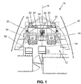
FIG. 1 is a plan view of a two-pilot cockpit layout of an aircraft according to the present invention; -
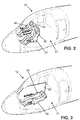
FIG. 2 is a perspective view of a two-pilot aircraft cockpit, as inFIG. 1 or in another aircraft, shown in normal flight operation; -
FIG. 3 is a perspective view of the two-pilot cockpit ofFIG. 2 shown with a pilot resting on a reclined seat in a screened privacy area; -
FIG. 4 is an enlarged view of the resting pilot, reclined seat, and screened privacy area ofFIG. 3 ; -
FIG. 5 is a representation of the aircraft ofFIGS 2-4 , shown for more complete diagrammatic illustration of onboard flight control system components, particularly for elements distributed through the fuselage and wings; and -
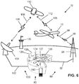
FIG. 6 is a perspective view of a system in which a ground-based pilot assumes copilot role for the aircraft ofFIGS. 3-4 , for example as a pilot rests. - The description set forth below in connection with the appended drawings is intended to be a description of various, illustrative embodiments of the disclosed subject matter. Specific features and functionalities are described in connection with each illustrative embodiment however, it will be apparent to those skilled in the art that the disclosed embodiments may be practiced without each of those specific features and functionalities. The aspects, features and functions described below in connection with one embodiment are intended to be applicable to the other embodiments described below except where expressly stated or where an aspect, feature or function is incompatible with an embodiment.
- Operational and equipment solutions are provided to efficiently and safely pilot long-range aircraft. To address this issue, an aircraft is remotely piloted, for example by a remote ground-based pilot. For example, a remote pilot can assume a copilot role, as one of two onboard pilots rests, and the alert onboard pilot assumes a primary pilot role. In effect, a third pilot is able to fly the aircraft, from afar, in cooperation with the onboard crew, enabling onboard pilots to rest one at a time. Even as an onboard pilot rests, two crew members, an onboard pilot and a remote pilot, are in control of the aircraft. The onboard pilot seats may be configured like premium class seating, such that the seats recline even to fully reclined or layback positions to attain true sleep. Such seats will achieve their fully reclined positions in a space similar to existing seats, thus requiring little cockpit redesign.
- Referring to
FIG. 1 , anaircraft 10 having a two-pilot cockpit 12 is shown as having two pilot seats longitudinally aligned and spaced from each other, each on a respective side of a centrallongitudinal axis 14 of the aircraft. The pilot-accessible forward components of an onboardflight control system 20 are emphasized by dashed line. Theflight control system 20 includes flight condition indicators 22 (FIGS. 1 ,5 ), aircraftsystem condition indicators 24, and flight control devices for use by the pilots in controlling the aircraft. The flight control system includes aninstrument panel 26 forward of the pilot seats, where many of the condition indicators and flight control devices are mounted to be readily accessible to pilots. The flight control system can have elements arranged and distributed elsewhere in the cockpit and aircraft. - Redundancy in the flight instruments and controls of the system permit either pilot to control the aircraft. By convention, the first or left-
side pilot seat 30 is typically assigned to a flight captain, and the second or right-side pilot seat 40 is typically assigned to a first officer. As a flight proceeds, the roles the two onboard pilots assume may be exchanged and shared as they cooperatively control the aircraft. Thus, thefirst pilot seat 30 andsecond pilot seat 40 are referenced in the drawings and in the following descriptions without limitation imposed upon what role, for example as primary pilot or copilot, any pilot assumes in any seat at any time. - A captain side joystick 32, a
captain navigation bag 34, a first officer side joystick 42, and a firstofficer navigation bag 44, are accordingly assigned at the left and right sides of the pilot seating arrangement. Acentral pedestal 50, between the pilot seats, serves as a base on which actuatable thrust controllers and other onboardflight control devices 52 are accessible to, and shared by, thefirst pilot 36 and second pilot 46 (FIG. 2 ).Flight control devices 52 are broadly considered in these descriptions to include thejoysticks - What additional seating is provided in the
cockpit 12 may be of the cabin attendant seating (CAS) variety, meaning thethird occupant seat 54 andfourth occupant seat 56 are smaller than the pilot seats, and do not, or only minimally, adjust and recline. Thethird occupant seat 54, aft or rearward of thepedestal 50 offers high visibility of the flight panel(s) 26 for observation. - In
FIG. 2 , a two-pilot cockpit 12 is shown during normal flight operation, in which an alertfirst pilot 36 occupies thefirst pilot seat 30, and an alertsecond pilot 46 occupies thesecond pilot seat 40. Theaircraft 10 represented inFIG. 2 may be the same model as the aircraft represented inFIG. 1 , or another aircraft. Thus, the aircraft represented inFIG. 1 is a non-limiting example. The two pilots (FIG. 2 ) cooperatively control theaircraft 10 in this mode. The distance and corresponding duration of the flight may exceed comfort or regulatory limits of the pilots, and rest may be needed accordingly. The maximum flight time for a pilot during a day is limited by regulation in some aeronautical jurisdictions, for example to nine hours, and eight hours at night. Flight duty period limits, accumulating both rest and alert times, can be higher, for example ranging from nine to fourteen hours, depending on how many segments are flown and the start time of the pilot's duty day. - To provide a rest period for an onboard pilot, the pilot seats according to these descriptions may recline, for example through a range of reclined positions from their upright positions (
FIG. 2 ) for use by alert pilots to fully reclined or layback positions to attain true sleep, as illustrated for thefirst pilot seat 30 inFIG. 3 , in which thefirst pilot 36 is in a lying rest position. Accordingly, thebackrest portion 37 of theseat 30 is pivotally lowered (FIG. 4 ) from its upright position ofFIG. 2 , and thelegrest portion 38 of the seat is pivotally raised inFIG. 4 from its forward reclined position ofFIG. 2 . The seat bottom 39 may articulate with movements of the backrest to avoid binding or pinching. In the fully reclined or layback positions, the backrests are pivotally lowered to horizontal positions, approximately aligned with the seat bottoms, and the legrests are pivotally raised. - A
partition wall 60 is shown inFIGS. 3 and4 as deployed between thefirst pilot seat 30 and second pilot seat, providing a screened privacy are to the resting pilot. Thepartition wall 60 deploys manually or automatically as either pilot seat is reclined, for example to the fully reclined position. Thepartition wall 60 stows manually or automatically as either reclined pilot seat is returned to its upright position. In the stowed condition, thepartition wall 60 is discretely stowed in a compact low-profile configuration or position. Thepartition wall 60 may be a thin rollable screen or sheet stowed on a spool or reel. Other wall constructions are within the scope of these descriptions. - The flight crew member on the
first pilot seat 30 may be resting to comply with maximum flight time limits set by aeronautical authorities, or airline operators or, the crew member may be resting by personal choice. The reclining pilot seats achieve their fully reclined positions in a space within the dimensions of thecockpit 12, and thepartition wall 60 provides a perception of privacy to the resting occupant of thefirst pilot seat 30 while occupying very little space in both the deployed condition ofFIGS. 3-4 and the stowed condition ofFIG. 2 . -
FIG. 5 represents theaircraft 10 ofFIGS. 2-4 in a more complete illustration to emphasize elements of the onboard flight control system components distributed through the fuselage 62 and wings 64. The aircraft includesonboard sensors 66,onboard actuators 68, and an onboardflight control system 20. Theonboard sensors 66 can include, as non-limiting examples, flight condition sensors including air speed sensors, altitude sensors, temperature sensors, and other sensors that detect flight conditions outside and inside theaircraft 10. Theonboard sensors 66 can also include aircraft system condition sensors including engine condition sensors, fuel level sensors, sensors that detect the status or condition of wing flaps and landing gear, and other sensors. - The
onboard actuators 68 can include, as non-limiting examples, actuators that adjust flight control surfaces such as the wing flaps, the vertical stabilizer rudder(s), and the horizontal stabilizer elevator(s). Theonboard actuators 68 further include actuators by which theaircraft 10 is controlled in both flight and ground movement. Thus, theonboard actuators 68 can control the landing gear, and both ground and air braking systems. Theonboard actuators 68 can also include devices that control engine speed and thrust. Thus, theaircraft 10 is piloted by control of theonboard actuators 68. Actuators are broadly referenced to include mechanically, electrically, and fluidly driven devices and mechanisms. - The onboard
fight control system 70 is in operative communication with theonboard sensors 66 to receive condition-related inputs from theonboard sensors 66 and to activate the onboard condition indicators according to the received condition-related inputs. As theonboard sensors 66 include flight condition sensors and aircraft system condition sensors, the onboard condition sensors accordingly include flight condition indicators 22 (FIGS. 1 and5 ) and aircraftsystem condition indicators 24 that respectively indicate flight and system conditions to the flight crew. The onboardflight control system 20 is in operative communication with theonboard actuators 68 to control and actuate theonboard actuators 68 according to the onboardflight control devices 52, thereby onboard piloting the aircraft. Dashed lines generally referenced inFIG. 5 aslinks 72 by which the onboardflight control system 20 is in operative communication withonboard sensors 66 andonboard actuators 68 are broadly considered to include electrical, mechanical, fluid, and optical links by which onboard sensors provide inputs to, and onboard actuators receive outputs from, the onboardflight control system 20.Onboard sensors 66,actuators 68, andlinks 72 therebetween, and the onboardflight control system 20, may have redundancies for assurance of flight control operations in the event one device or one system of redundant parallel devices and systems is inoperative or faulty. - Piloting is generally conducted by at least one onboard pilot. The onboard
flight control system 20 is operative to receive condition-related inputs from theonboard sensors 66, to activate the onboard condition indicators according to the received condition-related inputs, and, in an onboard piloting mode, to actuate theonboard actuators 68 according to the onboard flight control devices, thereby onboard piloting theaircraft 10. Control of theaircraft 10 is not necessarily exclusively executed by a single pilot of the two onboard pilots, who may cooperatively control the aircraft in the onboard piloting mode. - Aspects of a system 70 (
FIG. 6 ), for both onboard piloting and remote piloting of theaircraft 10, can now be described, with advantages thereof being particularly beneficial in view of theFIGS. 3-4 , in which apilot 36 rests in a fully reclinedpilot seat 30. As shown inFIG. 6 , a remoteflight control system 80 is used to pilot theaircraft 10 cooperatively with at least one alert onboard pilot. The remoteflight control system 80 is in electronic communication with the onboardflight control system 20 by way of a two-way communication channel including at least one wireless segment. - For example in
FIG. 6 , the remoteflight control system 80 is linked in a first two-way communication channel 90, by a ground-basedfirst link 92, to a land-to-air transceiver 94, which conveys two-way communications 96 between the remoteflight control system 80 and theaircraft 10 by way of awireless segment 98 of the first two-way communication channel 90. Additionally, in thesystem 70 as illustrated inFIG. 6 , which represents a non-limiting example, the remoteflight control system 80 is linked in a second two-way communication channel 100, by a ground-basedsecond link 102, to a land-to-satellite transceiver 104, which conveys two-way communications 106 between the remoteflight control system 80 and acommunications satellite 110 by way of awireless segment 108 of the second two-way communication channel 100. Thecommunications satellite 110 further conveys the two-way communications to and from the aircraft by awireless segment 112 of the second two-way communication channel 100. - By either or both of the first two-
way communication channel 90 and second two-way communication channel 100, or by arrangement not expressly illustrated but suggested by these non-limiting examples, the onboard pilotingsystem 70, at least in a remote piloting mode, transmits condition-related signals to the remoteflight control system 80 and receives flight control signals from the remote flight control system. - The remote
flight control system 80 as illustrated includesdisplays 120 such as LED and/or LCD displays that on which thecomputer system 140 graphically displays the flight condition indicators and aircraft system condition indicators. The remoteflight control system 80 includes input devices by which or according to which flight control signals are generated by the remote flight control system and transmitted to the onboard flight control system. The input devices can include, as non-limiting examples, ajoystick 122, for example in the form of a mouse in some embodiments, one ormore keyboards 124, and one or more touch screens. The remoteflight control system 80 can include audio output and audio input devices by which the remote pilot can maintain audio communications, such as voice communications, with the aircraft onboard pilots and/or land-based flight controllers as represented by aflight control tower 130 inFIG. 6 . - For example, by way of the
displays 120, the remoteflight control system 80 includes or displays flight condition indicators, aircraft system condition indicators, and flight control devices for use by a remote pilot in remotely piloting the aircraft. The remoteflight control system 80 includes an instrument panel, as represented by thedisplays 120, where many of the condition indicators and flight control devices are mounted, or graphically represented, to be readily accessible to aremote pilot 136. The remoteflight control system 80, in the illustrated non-limiting example, graphically displays flight condition indicators and aircraft system condition indicators that respectively indicate flight and system conditions as conveyed by the received condition-related signals. While other arrangements are within the scope of these descriptions, the remoteflight control system 80 ofFIG. 6 is generally computer-based, and accordingly includes acomputer system 140 such as a workstation, server, or PC. - The input devices, for example the
joystick 122 in the form of a mouse or other input device, serve as remote flight control devices by which theaircraft 10 is remotely piloted. The remoteflight control system 80, for example, may provide, to theremote pilot 136, any and all information available to onboard pilots. Thus, by use of thedisplays 120 and other benefits of the remoteflight control system 80, theremote pilot 136 is presented a simulated or remote cockpit and flying presentation. - As one of the onboard pilots is resting, optionally screened by the partition wall as shown in
FIG. 4 , the remote third pilot can assume a piloting role, in particular serving as copilot in a non-limiting example. Theremote pilot 136 may be simulated as placed into thecockpit 12 of theaircraft 10 by the use of respective virtual reality (VR) presentations within the cockpit and at the remoteflight control system 80. For example, thedisplays 120 at the remoteflight control system 80 may display the onboard alert pilot to theremote pilot 136. For example, thesecond pilot 46 may be displayed at the remoteflight control system 80 as thefirst pilot 36 rests according toFIGS. 3-4 . Similarly, displays at the onboardflight control system 20 andcockpit 12 may display theremote pilot 136 to the alert onboard pilot. For example, VR headrest displays may be used at one or each location. Thus, each alert pilot, both onboard and remote, may perceive the other pilot as present through VR presentation. - Accordingly, in various non-limiting examples, the
system 70 is provided for both onboard piloting and remote piloting anaircraft 10 having thereon at least one onboard pilot. The aircraft in a typical example will have two onboard pilot, one of which may rest at a time as an alert onboard pilot is assisted by the remote pilot via the remoteflight control system 80. The onboardflight control system 20 is operative to receive condition-related inputs from theonboard sensors 66, to activate the onboard condition indicators according to the received condition-related inputs. - The onboard
flight control system 20 may have both an onboard piloting mode, in which onboard actuators are actuated according to the onboard flight control devices, thereby onboard piloting the aircraft, and a remote piloting mode. At least in the remote piloting mode, the onboardflight control system 20 transmits the condition-related signals from theonboard sensors 66 to the remoteflight control system 80, and receives flight control signals from the remoteflight control system 80. The onboardflight control system 20 may actuate, according to the flight control signals received from the remoteflight control system 80, theonboard actuators 68 thereby remote piloting theaircraft 10. - The remote piloting mode may be entered upon either the onboard
first pilot seat 30 orsecond pilot seat 40 being adjusted to a fully reclined position, indicating that an onboard pilot is at rest. Each onboard pilot seat can include a respective seat position sensor 58 (FIG. 4 ) in electronic communication with the onboardflight control system 20, with the onboard flight control system being operative to alert the remoteflight control system 80 when the onboard pilot seat is adjusted to a reclined position. The onboardflight control system 20 may be automatically operative in the remote piloting mode upon either onboard pilot seat being adjusted to a reclined position, for example a fully reclined position. - To assure that one onboard pilot is alert in an upright pilot seat, the
first pilot seat 30 may be disposed in the reclined position thereof and thesecond pilot seat 40 may be disposed in the reclined position thereof at exclusive alternating times. Reclining both thefirst pilot seat 30 and thesecond pilot seat 40 may cause an alert action or alarm. Thefirst pilot seat 30 andsecond pilot seat 40 may be prevented from reclining or fully reclining at once by interface and control of seat pivots using controlled adjusters or locks, for example by the onboardflight control system 20, or interlinked mechanisms of the seats. - In the remote piloting mode, a
third pilot 136 may pilot theaircraft 10 cooperatively with the non-resting one of the onboardfirst pilot 36 andsecond pilot 46. The onboardflight control system 20 may automatically return to the onboard piloting mode when both the onboardfirst pilot seat 30 andsecond pilot seat 40 are returned to their upright positions. Thus, reclining either onboard pilot seat may automatically switch the onboardflight control system 20 from the onboard piloting mode to the remote piloting mode, and returning the reclined onboard seat to its upright position may automatically switch the onboard flight control system to the onboard piloting mode. - The
onboard sensors 66 relay information, via the onboardflight control system 20 and one or more communication channels (90,100), to thecomputer system 140 of the remoteflight control system 80, which has a processor where software is used to analyze the data received to confirm and indicate flight conditions and aircraft system conditions. The processor may be a component of a server, such as a digital computer also including input/output (I/O) interfaces, a network interface, a data store, and memory. The components may be communicatively coupled via a local interface such as one or more buses or other wired or wireless connections. The local interface may have additional elements such as controllers, buffers (caches), drivers, repeaters, and receivers, among others, to enable communications. Further, the local interface may include address, control, and/or data connections to enable appropriate communications among the components. - The processor of the
computing system 140 executes software instructions and may be any custom made or commercially available processor, a central processing unit (CPU), an auxiliary processor among several processors associated with the server, a semiconductor-based microprocessor (in the form of a microchip or chip set), or generally any device for executing software instructions. When in operation, the processor is configured to execute software stored within the memory, to communicate data to and from the memory, and to generally control operations of the server pursuant to the software instructions. The I/O interfaces may be used to receive user input from and/or for providing system output to one or more devices or components such as the displays, an aircraft network as represented by theflight control tower 130 inFIG. 6 , and flight crew accessible devices. I/O interfaces may include a serial port, a parallel port, a small computer system interface (SCSI), a serial ATA (SATA), a fibre channel, Infiniband, iSCSI, a PCI Express interface (PCI-x), an infrared (IR) interface, a radio frequency (RF) interface, and/or a universal serial bus (USB) interface. - A network interface may be used to enable the
computer system 140 to communicate on a network, such as the Internet, a wide area network (WAN), a local area network (LAN) such as a secure aircraft network, and the like, etc. The network interface may include address, control, and/or data connections to enable appropriate communications on the network. A data store may be used to store data. The data store may include any of volatile memory elements (e.g., random access memory (RAM, such as DRAM, SRAM, SDRAM, and the like)), nonvolatile memory elements (e.g., ROM, hard drive, tape, CDROM, and the like), and combinations thereof. Moreover, the data store may incorporate electronic, magnetic, optical, and/or other types of storage media. In one example, the data store may be located internal to the server such as, for example, an internal hard drive connected to the local interface in the server. Additionally, in another embodiment, the data store may be located external to the server such as, for example, an external hard drive connected to the I/O interfaces (e.g., SCSI or USB connection). In a further embodiment, the data store may be connected to the server through a network, such as, for example, a network attached file server. - The memory may include any of volatile memory elements (e.g., random access memory (RAM, such as DRAM, SRAM, SDRAM, etc.)), nonvolatile memory elements (e.g., ROM, hard drive, tape, CDROM, etc.), and combinations thereof. Moreover, the memory may incorporate electronic, magnetic, optical, and/or other types of storage media. The software in memory may include one or more software programs, each of which includes an ordered listing of executable instructions for implementing logical functions. The software in the memory includes a suitable operating system (O/S) and one or more programs. The operating system essentially controls the execution of other computer programs, such as the one or more programs, and provides scheduling, input-output control, file and data management, memory management, and communication control and related services. The one or more programs may be configured to implement the various processes, algorithms, methods, techniques, etc. described herein.
- To achieve reliability and direct connection, military communication protocols may be used, such as protocols used to control an unmanned aerial vehicle (UAV), and channeled to the remote
flight control system 80 andremote pilot 136. Communication protocols of the system for remotely piloting of theaircraft 10 with high security may be military grade while serving a civilian based aviation system. Remote flight control of the aircraft may be used to improve flight safety and security against incidents where smoke, low oxygen, or other health issues are problematic in the cockpit. Remote flight control of theaircraft 10 may be used in the event of a terrorist situation. The standard Extended Twin Operations (ETOPs), which describes an operation in which air carriers are allowed to fly an extended range over distances where airports and landing areas are sparse, such as long routes over the ocean, may be met by the system with improved security and crew redundancy by way of one or more remote pilots. - The
system 70 can increase the effective range of long-range aircraft without major changes to cabin installations onboard. In use with an aircraft that can fly long range, for example ten hours or more, thesystem 70 can be used to relieve onboard flight crew members in compliance with maximum flight times for a pilot during a day according to aviation regulations or airline operator standards. This means that point to point airport pairs that were previously connected via non-directed routes can now be directly connected in a single flight. For example, Dallas Fort Worth and Frankfort airports can be directly connected, whereas only flights between the east coast of the US and restricted locations in Europe were previously made by commercial passenger airline operators. - While the foregoing description provides embodiments of the invention by way of example only, it is envisioned that other embodiments that are within the scope of the invention as defined by the appended claims may perform similar functions and/or achieve similar results.
Claims (11)
- A system for both onboard piloting and remote piloting an aircraft (10) having thereon at least one onboard pilot, the system (70) comprising:an aircraft (10) including an onboard first pilot seat (30), onboard sensors (66), onboard actuators (68), and an onboard flight control system (20), the onboard flight control system (20) including onboard flight control devices (52) and onboard condition indicators mounted proximal the first pilot seat (30); anda remote flight control system (80) in electronic communication with the onboard flight control system (20) by way of a two-way communication channel (90) including at least one wireless segment, the remote flight control system (80) including remote flight control devices and remote condition indicators;wherein, the onboard flight control system (20) is operative to receive condition-related inputs from the onboard sensors (66), to activate the onboard condition indicators according to the received condition-related inputs, and:at least in an onboard piloting mode, to actuate the onboard actuators (68) according to the onboard flight control devices (52), thereby onboard piloting the aircraft; andat least in a remote piloting mode, transmit the condition-related signals to the remote flight control system (80), to receive flight control signals from the remote flight control system (80), and to actuate, according to the flight control signals received from the remote flight control system (80), the onboard actuators (68) thereby remote piloting the aircraft (10).
- The system according to claim 1, wherein the first pilot seat (30) is adjustable between an upright position and a reclined position, and wherein the onboard flight control system (20) is operative in the remote piloting mode when the first pilot seat (30) is in the reclined position.
- The system according to claim 2, wherein the aircraft (10) further includes an onboard second pilot seat (40) adjustable between an upright position and a reclined position, and wherein, the onboard flight control system (20) is operative in the remote piloting mode when the second pilot seat (40) is in the reclined position.
- The system according to claim 3, wherein the first pilot seat is in the reclined position thereof and the second pilot seat (40) is in the reclined position thereof at exclusive alternating times.
- The system according to one or more of the preceding claims, wherein the remote flight control system (80) includes at least one display (120) on which the remote condition indicators are graphically displayed.
- The system according to one or more of the preceding claims, wherein the aircraft (10) further includes an onboard second pilot seat (40) adjustable between an upright position and a reclined position, wherein the first pilot seat (30) is adjustable between an upright position and a reclined position, and wherein the aircraft (10) further includes a partition wall (60) deployable between the first pilot seat (30) and second pilot seat (40).
- The system according to claim 6, wherein the partition wall (60) stows automatically as either of the first pilot seat (30) and second pilot seat (40) is adjusted from the reclined position thereof to the upright position thereof.
- The system according to one or more of the preceding claims, wherein the aircraft (10) further includes an onboard second pilot seat (40), wherein, at least in the remote piloting mode, the remote pilot is simulated as placed into the aircraft (10) by a virtual reality (VR) presentation viewable at the second pilot seat (40).
- The system according to one or more of the preceding claims, wherein the aircraft (10) further includes an onboard second pilot seat (40), and wherein the remote piloting system (80) is used to extend the range of the aircraft (10) by permitting a first pilot (36) in the first pilot seat (30) and a second pilot (46) in the second pilot seat (40) to alternately rest as a third pilot (136) at the remote flight control system (80) pilots the aircraft (10) cooperatively with the non-resting one of the first pilot (36) and second pilot (46).
- The system according to one or more of the preceding claims, wherein the first pilot seat (30) comprises a seat position sensor (58) in electronic communication with the onboard flight control system (20), and wherein the onboard flight control system (20) is operative to alert the remote flight control system (80) when said onboard first pilot seat (30) is adjusted to a reclined position.
- The system (10) according to one or more of the preceding claims, wherein the first pilot seat (30) comprises a backrest pivotally adjustable from an upright position to a fully reclined approximately horizontal position.
Applications Claiming Priority (1)
| Application Number | Priority Date | Filing Date | Title |
|---|---|---|---|
| US16/555,139 US11535373B2 (en) | 2019-08-29 | 2019-08-29 | Methods and systems for remote piloting a two-pilot aircraft for extended flights |
Publications (2)
| Publication Number | Publication Date |
|---|---|
| EP3786057A1 true EP3786057A1 (en) | 2021-03-03 |
| EP3786057B1 EP3786057B1 (en) | 2023-07-26 |
Family
ID=68848202
Family Applications (1)
| Application Number | Title | Priority Date | Filing Date |
|---|---|---|---|
| EP19215092.8A Active EP3786057B1 (en) | 2019-08-29 | 2019-12-11 | System for both onboard piloting and remote piloting an aircraft |
Country Status (3)
| Country | Link |
|---|---|
| US (1) | US11535373B2 (en) |
| EP (1) | EP3786057B1 (en) |
| CN (1) | CN112441243B (en) |
Cited By (2)
| Publication number | Priority date | Publication date | Assignee | Title |
|---|---|---|---|---|
| US11535373B2 (en) | 2019-08-29 | 2022-12-27 | B/E Aerospace, Inc. | Methods and systems for remote piloting a two-pilot aircraft for extended flights |
| US20240343396A1 (en) * | 2023-04-11 | 2024-10-17 | B/E Aerospace, Inc. | Pilot sleeper seat with integrated rudder controls and lockout function |
Families Citing this family (8)
| Publication number | Priority date | Publication date | Assignee | Title |
|---|---|---|---|---|
| FR3090979B1 (en) * | 2018-12-19 | 2022-02-18 | Safran Electronics & Defense | Alternative piloting system intended to be integrated into a pre-existing aircraft |
| WO2020127710A1 (en) * | 2018-12-19 | 2020-06-25 | Safran Electronics & Defense | System for configuring an aircraft in a single-pilot mode or a two-pilot mode |
| US11543819B2 (en) * | 2019-02-25 | 2023-01-03 | Textron Innovations Inc. | Remote control unit having active feedback |
| CN114013630A (en) * | 2021-11-15 | 2022-02-08 | 中国商用飞机有限责任公司 | Aircraft cockpit and airplane |
| CN114384794A (en) * | 2022-03-24 | 2022-04-22 | 苏州挚途科技有限公司 | Vehicle remote driving control system and method |
| US12391401B2 (en) | 2023-08-02 | 2025-08-19 | Ami Industries, Inc. | Seat mounted inboard flight controllers for aircraft pilot seats |
| US12134476B1 (en) | 2023-08-07 | 2024-11-05 | Ami Industries, Inc. | Flight controller ingress and egress system |
| CN117755472A (en) * | 2024-01-23 | 2024-03-26 | 上海览翌航空科技有限公司 | Aircraft cockpit, aircraft and aircraft control method |
Citations (5)
| Publication number | Priority date | Publication date | Assignee | Title |
|---|---|---|---|---|
| US20060032978A1 (en) * | 2004-08-16 | 2006-02-16 | Matos Jeffrey A | Method and system for controlling a hijacked aircraft |
| US7099752B1 (en) * | 2003-10-27 | 2006-08-29 | Leslie Jae Lenell | Safelander |
| US7156344B1 (en) * | 2005-06-02 | 2007-01-02 | Airbus France | Long-haul airplane |
| US20170355282A1 (en) * | 2016-06-14 | 2017-12-14 | Lear Corporation | Seat position detection for seat assemblies |
| US20180290729A1 (en) * | 2015-10-20 | 2018-10-11 | Israel Aerospace Industries Ltd. | Method of operation yeilding extended range for single pilot aircraft and systems useful in conjunction therewith |
Family Cites Families (12)
| Publication number | Priority date | Publication date | Assignee | Title |
|---|---|---|---|---|
| US5803789A (en) | 1995-12-29 | 1998-09-08 | Dean; Bryan L. | Remote control toy including tilt switch hand controller |
| AU2002334708A1 (en) | 2001-10-01 | 2003-04-14 | Kline And Walker, Llc | Pfn/trac system faa upgrades for accountable remote and robotics control |
| US7614584B2 (en) * | 2006-12-21 | 2009-11-10 | The Boeing Company | Pilot rest for airplane |
| FR2910436B1 (en) * | 2006-12-26 | 2009-02-06 | Airbus Sas | FRONT PART OF AN AIRCRAFT INCLUDING A REST COMPARTMENT FOR AT LEAST ONE PILOT |
| FR2918642B1 (en) * | 2007-07-12 | 2013-11-29 | Airbus France | ADVANCED AIRCRAFT AIRCRAFT |
| DE102007041391A1 (en) * | 2007-08-31 | 2009-03-05 | Airbus Deutschland Gmbh | Secured cockpit with integrated lounge area and sanitary facilities |
| FR2923044B1 (en) * | 2007-10-31 | 2012-11-09 | Airbus France | DEVICE FOR MANAGING A REST FOR THE DRIVERS OF AN AIRCRAFT. |
| US9980298B2 (en) * | 2016-02-26 | 2018-05-22 | The Boeing Company | Method and system for integration of portable devices with flight deck displays |
| FR3074347B1 (en) * | 2017-11-24 | 2022-10-14 | Thales Sa | ELECTRONIC SYSTEM FOR REMOTE CONTROL OF DRONES, METHOD FOR COMPUTER PROGRAM ASSOCIATED |
| CN108945397B (en) * | 2018-04-24 | 2021-05-04 | 中国商用飞机有限责任公司北京民用飞机技术研究中心 | Flight driving system |
| US11235712B2 (en) * | 2018-08-08 | 2022-02-01 | Uatc, Llc | Automatically adjustable partition wall for an autonomous vehicle |
| US11535373B2 (en) | 2019-08-29 | 2022-12-27 | B/E Aerospace, Inc. | Methods and systems for remote piloting a two-pilot aircraft for extended flights |
-
2019
- 2019-08-29 US US16/555,139 patent/US11535373B2/en active Active
- 2019-12-11 EP EP19215092.8A patent/EP3786057B1/en active Active
- 2019-12-12 CN CN201911273302.5A patent/CN112441243B/en active Active
Patent Citations (5)
| Publication number | Priority date | Publication date | Assignee | Title |
|---|---|---|---|---|
| US7099752B1 (en) * | 2003-10-27 | 2006-08-29 | Leslie Jae Lenell | Safelander |
| US20060032978A1 (en) * | 2004-08-16 | 2006-02-16 | Matos Jeffrey A | Method and system for controlling a hijacked aircraft |
| US7156344B1 (en) * | 2005-06-02 | 2007-01-02 | Airbus France | Long-haul airplane |
| US20180290729A1 (en) * | 2015-10-20 | 2018-10-11 | Israel Aerospace Industries Ltd. | Method of operation yeilding extended range for single pilot aircraft and systems useful in conjunction therewith |
| US20170355282A1 (en) * | 2016-06-14 | 2017-12-14 | Lear Corporation | Seat position detection for seat assemblies |
Cited By (3)
| Publication number | Priority date | Publication date | Assignee | Title |
|---|---|---|---|---|
| US11535373B2 (en) | 2019-08-29 | 2022-12-27 | B/E Aerospace, Inc. | Methods and systems for remote piloting a two-pilot aircraft for extended flights |
| US20240343396A1 (en) * | 2023-04-11 | 2024-10-17 | B/E Aerospace, Inc. | Pilot sleeper seat with integrated rudder controls and lockout function |
| US12420934B2 (en) * | 2023-04-11 | 2025-09-23 | B/E Aerospace, Inc. | Pilot sleeper seat with integrated rudder controls and lockout function |
Also Published As
| Publication number | Publication date |
|---|---|
| US20210061462A1 (en) | 2021-03-04 |
| US11535373B2 (en) | 2022-12-27 |
| CN112441243A (en) | 2021-03-05 |
| EP3786057B1 (en) | 2023-07-26 |
| CN112441243B (en) | 2024-11-05 |
Similar Documents
| Publication | Publication Date | Title |
|---|---|---|
| US11535373B2 (en) | Methods and systems for remote piloting a two-pilot aircraft for extended flights | |
| US12179908B2 (en) | Method of operation yielding extended range for single pilot aircraft and systems useful in conjunction therewith | |
| US20180232097A1 (en) | Touch Screen Instrument Panel | |
| US20080001847A1 (en) | System and method of using a multi-view display | |
| US12012210B2 (en) | Multifunction dynamic visual display for interactive user experience | |
| US9555896B2 (en) | Aircraft flight control | |
| Lyons et al. | Aircraft and related factors in crashes involving spatial disorientation: 15 years of US Air Force data | |
| Hobbs | Unmanned aircraft systems | |
| Palmer | Understanding Air France 447 | |
| Landry | Human factors and ergonomics in aviation | |
| LI | Human factors in crashes of commuter airplanes | |
| CN117755472A (en) | Aircraft cockpit, aircraft and aircraft control method | |
| US10577082B2 (en) | Cockpit control of a fixed wing aircraft | |
| Murray et al. | Safety Review of Small Unmanned Aircraft Systems Operations | |
| Williams | Documentation of sensory information in the operation of unmanned aircraft systems | |
| Evans | Frequency of Specific Categories of Aviation Accidents and Incidents During 2001-2010 | |
| Ross | When will software have the right stuff? | |
| US11762837B2 (en) | Method and apparatus for updating and sharing an obstacle database for aircraft | |
| WO2025259633A1 (en) | Reduced-drag laminar flow fixed-wing aircraft - cabin | |
| Marks | Are you ready to get on a pilotless plane? | |
| Del Frate et al. | Recent flight test experience with uninhabited aerial vehicles at the NASA Dryden Flight Research Center | |
| Zeffert | Airliner flight deck design for crew co-ordination | |
| Feron et al. | Paths towards autonomy in commercial air operations | |
| Berth et al. | Research on integrated collimated cockpit visual and flight information system | |
| Hlinka et al. | Identification of major safety issues for a futuristic personal plane concept |
Legal Events
| Date | Code | Title | Description |
|---|---|---|---|
| PUAI | Public reference made under article 153(3) epc to a published international application that has entered the european phase |
Free format text: ORIGINAL CODE: 0009012 |
|
| STAA | Information on the status of an ep patent application or granted ep patent |
Free format text: STATUS: THE APPLICATION HAS BEEN PUBLISHED |
|
| AK | Designated contracting states |
Kind code of ref document: A1 Designated state(s): AL AT BE BG CH CY CZ DE DK EE ES FI FR GB GR HR HU IE IS IT LI LT LU LV MC MK MT NL NO PL PT RO RS SE SI SK SM TR |
|
| AX | Request for extension of the european patent |
Extension state: BA ME |
|
| RAP3 | Party data changed (applicant data changed or rights of an application transferred) |
Owner name: B/E AEROSPACE, INC. |
|
| STAA | Information on the status of an ep patent application or granted ep patent |
Free format text: STATUS: REQUEST FOR EXAMINATION WAS MADE |
|
| 17P | Request for examination filed |
Effective date: 20210830 |
|
| RBV | Designated contracting states (corrected) |
Designated state(s): AL AT BE BG CH CY CZ DE DK EE ES FI FR GB GR HR HU IE IS IT LI LT LU LV MC MK MT NL NO PL PT RO RS SE SI SK SM TR |
|
| GRAP | Despatch of communication of intention to grant a patent |
Free format text: ORIGINAL CODE: EPIDOSNIGR1 |
|
| STAA | Information on the status of an ep patent application or granted ep patent |
Free format text: STATUS: GRANT OF PATENT IS INTENDED |
|
| RIC1 | Information provided on ipc code assigned before grant |
Ipc: B64D 11/00 20060101ALN20230224BHEP Ipc: B60N 2/02 20060101ALN20230224BHEP Ipc: G08G 5/00 20060101ALN20230224BHEP Ipc: G05D 1/10 20060101ALN20230224BHEP Ipc: G05D 1/08 20060101ALN20230224BHEP Ipc: G05D 1/04 20060101ALN20230224BHEP Ipc: G05D 1/02 20060101ALN20230224BHEP Ipc: B60R 21/015 20060101ALI20230224BHEP Ipc: G05D 1/00 20060101ALI20230224BHEP Ipc: B64D 11/06 20060101ALI20230224BHEP Ipc: B64C 13/00 20060101AFI20230224BHEP |
|
| INTG | Intention to grant announced |
Effective date: 20230331 |
|
| RIC1 | Information provided on ipc code assigned before grant |
Ipc: B64D 11/00 20060101ALN20230321BHEP Ipc: B60N 2/02 20060101ALN20230321BHEP Ipc: G08G 5/00 20060101ALN20230321BHEP Ipc: G05D 1/10 20060101ALN20230321BHEP Ipc: G05D 1/08 20060101ALN20230321BHEP Ipc: G05D 1/04 20060101ALN20230321BHEP Ipc: G05D 1/02 20200101ALN20230321BHEP Ipc: B60R 21/015 20060101ALI20230321BHEP Ipc: G05D 1/00 20060101ALI20230321BHEP Ipc: B64D 11/06 20060101ALI20230321BHEP Ipc: B64C 13/00 20060101AFI20230321BHEP |
|
| GRAS | Grant fee paid |
Free format text: ORIGINAL CODE: EPIDOSNIGR3 |
|
| GRAA | (expected) grant |
Free format text: ORIGINAL CODE: 0009210 |
|
| STAA | Information on the status of an ep patent application or granted ep patent |
Free format text: STATUS: THE PATENT HAS BEEN GRANTED |
|
| P01 | Opt-out of the competence of the unified patent court (upc) registered |
Effective date: 20230608 |
|
| AK | Designated contracting states |
Kind code of ref document: B1 Designated state(s): AL AT BE BG CH CY CZ DE DK EE ES FI FR GB GR HR HU IE IS IT LI LT LU LV MC MK MT NL NO PL PT RO RS SE SI SK SM TR |
|
| REG | Reference to a national code |
Ref country code: CH Ref legal event code: EP |
|
| REG | Reference to a national code |
Ref country code: IE Ref legal event code: FG4D |
|
| REG | Reference to a national code |
Ref country code: DE Ref legal event code: R096 Ref document number: 602019033455 Country of ref document: DE |
|
| REG | Reference to a national code |
Ref country code: LT Ref legal event code: MG9D |
|
| REG | Reference to a national code |
Ref country code: NL Ref legal event code: MP Effective date: 20230726 |
|
| REG | Reference to a national code |
Ref country code: AT Ref legal event code: MK05 Ref document number: 1591680 Country of ref document: AT Kind code of ref document: T Effective date: 20230726 |
|
| PG25 | Lapsed in a contracting state [announced via postgrant information from national office to epo] |
Ref country code: NL Free format text: LAPSE BECAUSE OF FAILURE TO SUBMIT A TRANSLATION OF THE DESCRIPTION OR TO PAY THE FEE WITHIN THE PRESCRIBED TIME-LIMIT Effective date: 20230726 |
|
| PG25 | Lapsed in a contracting state [announced via postgrant information from national office to epo] |
Ref country code: GR Free format text: LAPSE BECAUSE OF FAILURE TO SUBMIT A TRANSLATION OF THE DESCRIPTION OR TO PAY THE FEE WITHIN THE PRESCRIBED TIME-LIMIT Effective date: 20231027 |
|
| PG25 | Lapsed in a contracting state [announced via postgrant information from national office to epo] |
Ref country code: IS Free format text: LAPSE BECAUSE OF FAILURE TO SUBMIT A TRANSLATION OF THE DESCRIPTION OR TO PAY THE FEE WITHIN THE PRESCRIBED TIME-LIMIT Effective date: 20231126 |
|
| PG25 | Lapsed in a contracting state [announced via postgrant information from national office to epo] |
Ref country code: SE Free format text: LAPSE BECAUSE OF FAILURE TO SUBMIT A TRANSLATION OF THE DESCRIPTION OR TO PAY THE FEE WITHIN THE PRESCRIBED TIME-LIMIT Effective date: 20230726 Ref country code: RS Free format text: LAPSE BECAUSE OF FAILURE TO SUBMIT A TRANSLATION OF THE DESCRIPTION OR TO PAY THE FEE WITHIN THE PRESCRIBED TIME-LIMIT Effective date: 20230726 Ref country code: PT Free format text: LAPSE BECAUSE OF FAILURE TO SUBMIT A TRANSLATION OF THE DESCRIPTION OR TO PAY THE FEE WITHIN THE PRESCRIBED TIME-LIMIT Effective date: 20231127 Ref country code: NO Free format text: LAPSE BECAUSE OF FAILURE TO SUBMIT A TRANSLATION OF THE DESCRIPTION OR TO PAY THE FEE WITHIN THE PRESCRIBED TIME-LIMIT Effective date: 20231026 Ref country code: LV Free format text: LAPSE BECAUSE OF FAILURE TO SUBMIT A TRANSLATION OF THE DESCRIPTION OR TO PAY THE FEE WITHIN THE PRESCRIBED TIME-LIMIT Effective date: 20230726 Ref country code: LT Free format text: LAPSE BECAUSE OF FAILURE TO SUBMIT A TRANSLATION OF THE DESCRIPTION OR TO PAY THE FEE WITHIN THE PRESCRIBED TIME-LIMIT Effective date: 20230726 Ref country code: IS Free format text: LAPSE BECAUSE OF FAILURE TO SUBMIT A TRANSLATION OF THE DESCRIPTION OR TO PAY THE FEE WITHIN THE PRESCRIBED TIME-LIMIT Effective date: 20231126 Ref country code: HR Free format text: LAPSE BECAUSE OF FAILURE TO SUBMIT A TRANSLATION OF THE DESCRIPTION OR TO PAY THE FEE WITHIN THE PRESCRIBED TIME-LIMIT Effective date: 20230726 Ref country code: GR Free format text: LAPSE BECAUSE OF FAILURE TO SUBMIT A TRANSLATION OF THE DESCRIPTION OR TO PAY THE FEE WITHIN THE PRESCRIBED TIME-LIMIT Effective date: 20231027 Ref country code: FI Free format text: LAPSE BECAUSE OF FAILURE TO SUBMIT A TRANSLATION OF THE DESCRIPTION OR TO PAY THE FEE WITHIN THE PRESCRIBED TIME-LIMIT Effective date: 20230726 Ref country code: AT Free format text: LAPSE BECAUSE OF FAILURE TO SUBMIT A TRANSLATION OF THE DESCRIPTION OR TO PAY THE FEE WITHIN THE PRESCRIBED TIME-LIMIT Effective date: 20230726 |
|
| PG25 | Lapsed in a contracting state [announced via postgrant information from national office to epo] |
Ref country code: PL Free format text: LAPSE BECAUSE OF FAILURE TO SUBMIT A TRANSLATION OF THE DESCRIPTION OR TO PAY THE FEE WITHIN THE PRESCRIBED TIME-LIMIT Effective date: 20230726 |
|
| PG25 | Lapsed in a contracting state [announced via postgrant information from national office to epo] |
Ref country code: ES Free format text: LAPSE BECAUSE OF FAILURE TO SUBMIT A TRANSLATION OF THE DESCRIPTION OR TO PAY THE FEE WITHIN THE PRESCRIBED TIME-LIMIT Effective date: 20230726 |
|
| REG | Reference to a national code |
Ref country code: DE Ref legal event code: R097 Ref document number: 602019033455 Country of ref document: DE |
|
| PG25 | Lapsed in a contracting state [announced via postgrant information from national office to epo] |
Ref country code: SM Free format text: LAPSE BECAUSE OF FAILURE TO SUBMIT A TRANSLATION OF THE DESCRIPTION OR TO PAY THE FEE WITHIN THE PRESCRIBED TIME-LIMIT Effective date: 20230726 Ref country code: RO Free format text: LAPSE BECAUSE OF FAILURE TO SUBMIT A TRANSLATION OF THE DESCRIPTION OR TO PAY THE FEE WITHIN THE PRESCRIBED TIME-LIMIT Effective date: 20230726 Ref country code: ES Free format text: LAPSE BECAUSE OF FAILURE TO SUBMIT A TRANSLATION OF THE DESCRIPTION OR TO PAY THE FEE WITHIN THE PRESCRIBED TIME-LIMIT Effective date: 20230726 Ref country code: EE Free format text: LAPSE BECAUSE OF FAILURE TO SUBMIT A TRANSLATION OF THE DESCRIPTION OR TO PAY THE FEE WITHIN THE PRESCRIBED TIME-LIMIT Effective date: 20230726 Ref country code: DK Free format text: LAPSE BECAUSE OF FAILURE TO SUBMIT A TRANSLATION OF THE DESCRIPTION OR TO PAY THE FEE WITHIN THE PRESCRIBED TIME-LIMIT Effective date: 20230726 Ref country code: CZ Free format text: LAPSE BECAUSE OF FAILURE TO SUBMIT A TRANSLATION OF THE DESCRIPTION OR TO PAY THE FEE WITHIN THE PRESCRIBED TIME-LIMIT Effective date: 20230726 Ref country code: SK Free format text: LAPSE BECAUSE OF FAILURE TO SUBMIT A TRANSLATION OF THE DESCRIPTION OR TO PAY THE FEE WITHIN THE PRESCRIBED TIME-LIMIT Effective date: 20230726 |
|
| PG25 | Lapsed in a contracting state [announced via postgrant information from national office to epo] |
Ref country code: IT Free format text: LAPSE BECAUSE OF FAILURE TO SUBMIT A TRANSLATION OF THE DESCRIPTION OR TO PAY THE FEE WITHIN THE PRESCRIBED TIME-LIMIT Effective date: 20230726 |
|
| PLBE | No opposition filed within time limit |
Free format text: ORIGINAL CODE: 0009261 |
|
| STAA | Information on the status of an ep patent application or granted ep patent |
Free format text: STATUS: NO OPPOSITION FILED WITHIN TIME LIMIT |
|
| 26N | No opposition filed |
Effective date: 20240429 |
|
| PG25 | Lapsed in a contracting state [announced via postgrant information from national office to epo] |
Ref country code: SI Free format text: LAPSE BECAUSE OF FAILURE TO SUBMIT A TRANSLATION OF THE DESCRIPTION OR TO PAY THE FEE WITHIN THE PRESCRIBED TIME-LIMIT Effective date: 20230726 |
|
| REG | Reference to a national code |
Ref country code: CH Ref legal event code: PL |
|
| PG25 | Lapsed in a contracting state [announced via postgrant information from national office to epo] |
Ref country code: LU Free format text: LAPSE BECAUSE OF NON-PAYMENT OF DUE FEES Effective date: 20231211 |
|
| PG25 | Lapsed in a contracting state [announced via postgrant information from national office to epo] |
Ref country code: MC Free format text: LAPSE BECAUSE OF FAILURE TO SUBMIT A TRANSLATION OF THE DESCRIPTION OR TO PAY THE FEE WITHIN THE PRESCRIBED TIME-LIMIT Effective date: 20230726 |
|
| REG | Reference to a national code |
Ref country code: BE Ref legal event code: MM Effective date: 20231231 |
|
| PG25 | Lapsed in a contracting state [announced via postgrant information from national office to epo] |
Ref country code: MC Free format text: LAPSE BECAUSE OF FAILURE TO SUBMIT A TRANSLATION OF THE DESCRIPTION OR TO PAY THE FEE WITHIN THE PRESCRIBED TIME-LIMIT Effective date: 20230726 Ref country code: LU Free format text: LAPSE BECAUSE OF NON-PAYMENT OF DUE FEES Effective date: 20231211 |
|
| REG | Reference to a national code |
Ref country code: IE Ref legal event code: MM4A |
|
| PG25 | Lapsed in a contracting state [announced via postgrant information from national office to epo] |
Ref country code: IE Free format text: LAPSE BECAUSE OF NON-PAYMENT OF DUE FEES Effective date: 20231211 |
|
| PG25 | Lapsed in a contracting state [announced via postgrant information from national office to epo] |
Ref country code: BE Free format text: LAPSE BECAUSE OF NON-PAYMENT OF DUE FEES Effective date: 20231231 |
|
| PG25 | Lapsed in a contracting state [announced via postgrant information from national office to epo] |
Ref country code: CH Free format text: LAPSE BECAUSE OF NON-PAYMENT OF DUE FEES Effective date: 20231231 |
|
| PG25 | Lapsed in a contracting state [announced via postgrant information from national office to epo] |
Ref country code: IE Free format text: LAPSE BECAUSE OF NON-PAYMENT OF DUE FEES Effective date: 20231211 Ref country code: CH Free format text: LAPSE BECAUSE OF NON-PAYMENT OF DUE FEES Effective date: 20231231 Ref country code: BE Free format text: LAPSE BECAUSE OF NON-PAYMENT OF DUE FEES Effective date: 20231231 |
|
| PG25 | Lapsed in a contracting state [announced via postgrant information from national office to epo] |
Ref country code: BG Free format text: LAPSE BECAUSE OF FAILURE TO SUBMIT A TRANSLATION OF THE DESCRIPTION OR TO PAY THE FEE WITHIN THE PRESCRIBED TIME-LIMIT Effective date: 20230726 |
|
| PG25 | Lapsed in a contracting state [announced via postgrant information from national office to epo] |
Ref country code: BG Free format text: LAPSE BECAUSE OF FAILURE TO SUBMIT A TRANSLATION OF THE DESCRIPTION OR TO PAY THE FEE WITHIN THE PRESCRIBED TIME-LIMIT Effective date: 20230726 |
|
| PG25 | Lapsed in a contracting state [announced via postgrant information from national office to epo] |
Ref country code: CY Free format text: LAPSE BECAUSE OF FAILURE TO SUBMIT A TRANSLATION OF THE DESCRIPTION OR TO PAY THE FEE WITHIN THE PRESCRIBED TIME-LIMIT; INVALID AB INITIO Effective date: 20191211 |
|
| PG25 | Lapsed in a contracting state [announced via postgrant information from national office to epo] |
Ref country code: HU Free format text: LAPSE BECAUSE OF FAILURE TO SUBMIT A TRANSLATION OF THE DESCRIPTION OR TO PAY THE FEE WITHIN THE PRESCRIBED TIME-LIMIT; INVALID AB INITIO Effective date: 20191211 |
|
| PG25 | Lapsed in a contracting state [announced via postgrant information from national office to epo] |
Ref country code: TR Free format text: LAPSE BECAUSE OF FAILURE TO SUBMIT A TRANSLATION OF THE DESCRIPTION OR TO PAY THE FEE WITHIN THE PRESCRIBED TIME-LIMIT Effective date: 20230726 |
|
| PGFP | Annual fee paid to national office [announced via postgrant information from national office to epo] |
Ref country code: DE Payment date: 20251126 Year of fee payment: 7 |
|
| PGFP | Annual fee paid to national office [announced via postgrant information from national office to epo] |
Ref country code: GB Payment date: 20251119 Year of fee payment: 7 |
|
| PGFP | Annual fee paid to national office [announced via postgrant information from national office to epo] |
Ref country code: FR Payment date: 20251120 Year of fee payment: 7 |