EP3785417B1 - Technologies for detecting cyber-attacks against electrical distribution devices - Google Patents
Technologies for detecting cyber-attacks against electrical distribution devices Download PDFInfo
- Publication number
- EP3785417B1 EP3785417B1 EP19728766.7A EP19728766A EP3785417B1 EP 3785417 B1 EP3785417 B1 EP 3785417B1 EP 19728766 A EP19728766 A EP 19728766A EP 3785417 B1 EP3785417 B1 EP 3785417B1
- Authority
- EP
- European Patent Office
- Prior art keywords
- controller
- transformer
- temperature
- measured value
- expected
- Prior art date
- Legal status (The legal status is an assumption and is not a legal conclusion. Google has not performed a legal analysis and makes no representation as to the accuracy of the status listed.)
- Active
Links
Images






Classifications
-
- H—ELECTRICITY
- H04—ELECTRIC COMMUNICATION TECHNIQUE
- H04L—TRANSMISSION OF DIGITAL INFORMATION, e.g. TELEGRAPHIC COMMUNICATION
- H04L63/00—Network architectures or network communication protocols for network security
- H04L63/14—Network architectures or network communication protocols for network security for detecting or protecting against malicious traffic
- H04L63/1408—Network architectures or network communication protocols for network security for detecting or protecting against malicious traffic by monitoring network traffic
- H04L63/1416—Event detection, e.g. attack signature detection
-
- H—ELECTRICITY
- H04—ELECTRIC COMMUNICATION TECHNIQUE
- H04L—TRANSMISSION OF DIGITAL INFORMATION, e.g. TELEGRAPHIC COMMUNICATION
- H04L63/00—Network architectures or network communication protocols for network security
- H04L63/20—Network architectures or network communication protocols for network security for managing network security; network security policies in general
-
- G—PHYSICS
- G05—CONTROLLING; REGULATING
- G05B—CONTROL OR REGULATING SYSTEMS IN GENERAL; FUNCTIONAL ELEMENTS OF SUCH SYSTEMS; MONITORING OR TESTING ARRANGEMENTS FOR SUCH SYSTEMS OR ELEMENTS
- G05B23/00—Testing or monitoring of control systems or parts thereof
- G05B23/02—Electric testing or monitoring
- G05B23/0205—Electric testing or monitoring by means of a monitoring system capable of detecting and responding to faults
- G05B23/0218—Electric testing or monitoring by means of a monitoring system capable of detecting and responding to faults characterised by the fault detection method dealing with either existing or incipient faults
- G05B23/0243—Electric testing or monitoring by means of a monitoring system capable of detecting and responding to faults characterised by the fault detection method dealing with either existing or incipient faults model based detection method, e.g. first-principles knowledge model
- G05B23/0254—Electric testing or monitoring by means of a monitoring system capable of detecting and responding to faults characterised by the fault detection method dealing with either existing or incipient faults model based detection method, e.g. first-principles knowledge model based on a quantitative model, e.g. mathematical relationships between inputs and outputs; functions: observer, Kalman filter, residual calculation, Neural Networks
-
- G—PHYSICS
- G06—COMPUTING OR CALCULATING; COUNTING
- G06F—ELECTRIC DIGITAL DATA PROCESSING
- G06F21/00—Security arrangements for protecting computers, components thereof, programs or data against unauthorised activity
- G06F21/50—Monitoring users, programs or devices to maintain the integrity of platforms, e.g. of processors, firmware or operating systems
- G06F21/55—Detecting local intrusion or implementing counter-measures
- G06F21/552—Detecting local intrusion or implementing counter-measures involving long-term monitoring or reporting
-
- G—PHYSICS
- G06—COMPUTING OR CALCULATING; COUNTING
- G06F—ELECTRIC DIGITAL DATA PROCESSING
- G06F21/00—Security arrangements for protecting computers, components thereof, programs or data against unauthorised activity
- G06F21/50—Monitoring users, programs or devices to maintain the integrity of platforms, e.g. of processors, firmware or operating systems
- G06F21/55—Detecting local intrusion or implementing counter-measures
- G06F21/554—Detecting local intrusion or implementing counter-measures involving event detection and direct action
-
- H—ELECTRICITY
- H04—ELECTRIC COMMUNICATION TECHNIQUE
- H04L—TRANSMISSION OF DIGITAL INFORMATION, e.g. TELEGRAPHIC COMMUNICATION
- H04L63/00—Network architectures or network communication protocols for network security
- H04L63/14—Network architectures or network communication protocols for network security for detecting or protecting against malicious traffic
- H04L63/1408—Network architectures or network communication protocols for network security for detecting or protecting against malicious traffic by monitoring network traffic
-
- H—ELECTRICITY
- H04—ELECTRIC COMMUNICATION TECHNIQUE
- H04L—TRANSMISSION OF DIGITAL INFORMATION, e.g. TELEGRAPHIC COMMUNICATION
- H04L63/00—Network architectures or network communication protocols for network security
- H04L63/14—Network architectures or network communication protocols for network security for detecting or protecting against malicious traffic
- H04L63/1408—Network architectures or network communication protocols for network security for detecting or protecting against malicious traffic by monitoring network traffic
- H04L63/1425—Traffic logging, e.g. anomaly detection
-
- G—PHYSICS
- G05—CONTROLLING; REGULATING
- G05B—CONTROL OR REGULATING SYSTEMS IN GENERAL; FUNCTIONAL ELEMENTS OF SUCH SYSTEMS; MONITORING OR TESTING ARRANGEMENTS FOR SUCH SYSTEMS OR ELEMENTS
- G05B19/00—Program-control systems
- G05B19/02—Program-control systems electric
- G05B19/04—Program control other than numerical control, i.e. in sequence controllers or logic controllers
- G05B19/042—Program control other than numerical control, i.e. in sequence controllers or logic controllers using digital processors
- G05B19/0428—Safety, monitoring
-
- Y—GENERAL TAGGING OF NEW TECHNOLOGICAL DEVELOPMENTS; GENERAL TAGGING OF CROSS-SECTIONAL TECHNOLOGIES SPANNING OVER SEVERAL SECTIONS OF THE IPC; TECHNICAL SUBJECTS COVERED BY FORMER USPC CROSS-REFERENCE ART COLLECTIONS [XRACs] AND DIGESTS
- Y04—INFORMATION OR COMMUNICATION TECHNOLOGIES HAVING AN IMPACT ON OTHER TECHNOLOGY AREAS
- Y04S—SYSTEMS INTEGRATING TECHNOLOGIES RELATED TO POWER NETWORK OPERATION, COMMUNICATION OR INFORMATION TECHNOLOGIES FOR IMPROVING THE ELECTRICAL POWER GENERATION, TRANSMISSION, DISTRIBUTION, MANAGEMENT OR USAGE, i.e. SMART GRIDS
- Y04S40/00—Systems for electrical power generation, transmission, distribution or end-user application management characterised by the use of communication or information technologies, or communication or information technology specific aspects supporting them
- Y04S40/20—Information technology specific aspects, e.g. CAD, simulation, modelling, system security
Definitions
- ICS industrial control systems
- asset monitoring devices employing sensors for reporting voltage, current, temperature, dissolved gas or oil quality analysis, diminishment in the performance of components in the grid (e.g., bushing or tap changers), and other measurements are becoming more common for transformers.
- These monitoring devices are beginning to feed into automated substations to provide information about the overall condition of the transformers and their onboard components and to potentially prompt automated control actions.
- transformer tap changer controllers that are microprocessor-based and that have the ability to process remotely issued commands for changing the tap settings (e.g., commands submitted to the controller through a network).
- US 2014/0189860 A1 relates to devices, methods, and systems for control system cybersecurity.
- US 2016/0118186 A1 relates to a hardened inductive device and systems and methods for protecting the inductive device from impact.
- EP 2 033 060 A2 relates to a system for real-time optimization of power resources on an electrical system
- the present disclosure provides a method for securing a transformer.
- the method includes determining, by a controller of the transformer, a first measured value of a first operational parameter of the transformer based upon one or more signals received from one or more sensors of the transformer.
- the method also includes determining, by the controller, a second measured value of a second operational parameter of the transformer based upon one or more signals received from the one or more sensors of the transformer.
- the method includes calculating, by the controller, a first expected value of the first operational parameter based on the second measured value of the second operational parameter and a model of the transformer that relates the first and second operational parameters.
- the method includes comparing, by the controller, the first measured value of the first operational parameter to the first expected value of the first operational parameter and identifying, by the controller, when a difference between the first measured value and the first expected value exceeds a first threshold.
- the present disclosure provides a controller for securing a transformer.
- the controller includes circuitry to determine a first measured value of a first operational parameter of the transformer based upon one or more signals received from one or more sensors of the transformer.
- the circuitry is also to determine a second measured value of a second operational parameter of the transformer based upon one or more signals received from the one or more sensors of the transformer.
- the circuitry is to calculate a first expected value of the first operational parameter based on the second measured value of the second operational parameter and a model of the transformer that relates the first and second operational parameters, compare the first measured value of the first operational parameter to the first expected value of the first operational parameter, and identify when a difference between the first measured value and the first expected value exceeds a first threshold.
- the present disclosure provides one or more machine-readable storage media having a plurality of instructions stored thereon that, in response to being executed, cause a controller to determine a first measured value of a first operational parameter of a transformer based upon one or more signals received from one or more sensors of the transformer.
- the instructions further cause the controller to determine a second measured value of a second operational parameter of the transformer based upon one or more signals received from the one or more sensors of the transformer, calculate a first expected value of the first operational parameter based on the second measured value of the second operational parameter and a model of the transformer that relates the first and second operational parameters, compare the first measured value of the first operational parameter to the first expected value of the first operational parameter, and identify when a difference between the first measured value and the first expected value exceeds a first threshold.
- references in the specification to "one embodiment,” “an embodiment,” “an illustrative embodiment,” etc., indicate that the embodiment described may include a particular feature, structure, or characteristic, but every embodiment may or may not necessarily include that particular feature, structure, or characteristic. Moreover, such phrases are not necessarily referring to the same embodiment. Further, when a particular feature, structure, or characteristic is described in connection with an embodiment, it is submitted that it is within the knowledge of one skilled in the art to effect such feature, structure, or characteristic in connection with other embodiments whether or not explicitly described.
- items included in a list in the form of "at least one A, B, and C” can mean (A); (B); (C); (A and B); (A and C); (B and C); or (A, B, and C).
- items listed in the form of "at least one of A, B, or C” can mean (A); (B); (C); (A and B); (A and C); (B and C); or (A, B, and C).
- the disclosed embodiments may be implemented, in some cases, in hardware, firmware, software, or any combination thereof.
- the disclosed embodiments may also be implemented as instructions carried by or stored on a transitory or non-transitory machine-readable (e.g., computer-readable) storage medium, which may be read and executed by one or more processors.
- a machine-readable storage medium may be embodied as any storage device, mechanism, or other physical structure for storing or transmitting information in a form readable by a machine (e.g., a volatile or non-volatile memory, a media disc, or other media device).
- a system 100 for detecting cyber-attacks against electrical distribution devices includes a set of transformers (i.e., electrical distribution devices) 110, 112, each of which may provide electricity to one or more other devices (not shown), and a control system 120 (e.g., an industrial control system) communicatively coupled to the transformers 110, 112 through a network 130.
- transformers i.e., electrical distribution devices
- control system 120 e.g., an industrial control system
- Each transformer 110, 112 may be embodied as any device or circuitry (e.g., a combination of power electronics and digital electronics, etc.) capable of selectively increasing or decreasing a voltage of an alternating current, such as by transferring electrical energy from a first coil to a second coil through electromagnetic induction using variable turn ratios selected in discrete steps (e.g., with a tap changer) or by other methods, such as by utilizing power electronics to convert alternating current to direct current and back to alternating current (e.g., in a solid state transformer).
- a device or circuitry e.g., a combination of power electronics and digital electronics, etc.
- each transformer includes sensors 150, 152 for reporting operational parameters, which may be embodied as any data indicative of conditions (temperatures in one or more portions of the transformer 110, 112, an electrical current in a portion of the transformer, a voltage in a portion of the transformer, etc.) of the transformer 110, 112 at any given time.
- Each transformer 110, 112 may additionally include a coolant fluid tank 160, 162 which may be embodied as a container of a fluid (e.g., oil) used to cool one or more components of the corresponding transformer 110, 112.
- a fluid e.g., oil
- a controller 140 which may be included in each transformer 110, 112 and/or located in the control system 120 obtains measurements, from the sensors 150, 152, of operational parameters of the corresponding transformer 110, 112, applies those measurements to a mathematical model of the relationship between operational parameters of the transformer to determine whether the reported measurements share the same relationship (e.g., by calculating an expected temperature from a reported electrical current), accounting for potential noise in the measurements, and if the relationship from the reported measurements diverges from the relationship indicated in the model by a threshold amount (e.g., the reported temperature exceeds the expected temperature by a predefined threshold amount), determining that the transformer may be subject to a cyber-attack and performing a responsive action, such as generating an alert.
- the system 100 may provide improved security against cyber-attacks as compared to typical electrical distribution systems.
- the controller 140 may be embodied as any type of device (e.g., a computer) capable of performing the functions described herein, including determining a first measured value of a first operational parameter of the transformer based upon one or more signals received from one or more sensors of the transformer, determining a second measured value of a second operational parameter of the transformer based upon one or more signals received from the one or more sensors of the transformer, calculating a first expected value of the first operational parameter based on the second measured value of the second operational parameter and a model of the transformer that relates the first and second operational parameters, comparing the first measured value of the first operational parameter to the first expected value of the first operational parameter, and identifying when a difference between the first measured value and the first expected value exceeds a first threshold.
- a computer capable of performing the functions described herein, including determining a first measured value of a first operational parameter of the transformer based upon one or more signals received from one or more sensors of the transformer, determining a second measured value of a second operational parameter of the transformer based upon
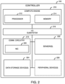
- the illustrative controller 140 includes a compute engine 210, an input/output (I/O) subsystem 216, communication circuitry 218, and one or more data storage devices 224.
- the controller 140 may include other or additional components, such as those commonly found in a computer (e.g., display, peripheral devices, etc.). Additionally, in some embodiments, one or more of the illustrative components may be incorporated in, or otherwise form a portion of, another component.
- the compute engine 210 may be embodied as any type of device or collection of devices capable of performing various compute functions described below.
- the compute engine 210 may be embodied as a single device such as an integrated circuit, an embedded system, a field-programmable gate array (FPGA), a system-on-a-chip (SOC), or other integrated system or device.
- the compute engine 210 includes or is embodied as a processor 212 and a memory 214.
- the processor 212 may be embodied as any type of processor capable of performing the functions described herein.
- the processor 212 may be embodied as a microcontroller, a single or multi-core processor(s), or other processor or processing/controlling circuit.
- the processor 212 may be embodied as, include, or be coupled to an FPGA, an application specific integrated circuit (ASIC), reconfigurable hardware or hardware circuitry, or other specialized hardware to facilitate performance of the functions described herein.
- ASIC application specific integrated circuit
- the main memory 214 may be embodied as any type of volatile (e.g., dynamic random access memory (DRAM), etc.) or non-volatile memory or data storage capable of performing the functions described herein. Volatile memory may be a storage medium that requires power to maintain the state of data stored by the medium. In some embodiments, all or a portion of the main memory 214 may be integrated into the processor 212. In operation, the main memory 214 may store various software and data used during operation such as operational parameters of a transformer 110, 112, thresholds, a mathematical model of the transformer 110, 112, applications, programs, libraries, and drivers.
- DRAM dynamic random access memory
- the compute engine 210 is communicatively coupled to other components of the controller 140 via the I/O subsystem 216, which may be embodied as circuitry and/or components to facilitate input/output operations with the compute engine 210 (e.g., with the processor 212 and/or the main memory 214) and other components of the controller 140.
- the I/O subsystem 216 may be embodied as, or otherwise include, memory controller hubs, input/output control hubs, integrated sensor hubs, firmware devices, communication links (e.g., point-to-point links, bus links, wires, cables, light guides, printed circuit board traces, etc.), and/or other components and subsystems to facilitate the input/output operations.
- the I/O subsystem 216 may form a portion of a system-on-a-chip (SoC) and be incorporated, along with one or more of the processor 212, the main memory 214, and other components of the controller 140, into the compute engine 210.
- SoC system-on-a-chip
- the communication circuitry 218 may be embodied as any communication circuit, device, or collection thereof, capable of enabling communications over the network 130 between the controller 140 and another compute device (e.g., one or more compute devices in the control system 120, etc.).
- the communication circuitry 218 may be configured to use any one or more communication technology (e.g., wired or wireless communications) and associated protocols (e.g., Ethernet, Bluetooth ® , Wi-Fi ® , WiMAX, etc.) to effect such communication.
- the illustrative communication circuitry 218 includes a network interface controller (NIC) 210.
- the NIC 220 may be embodied as one or more add-in-boards, daughter cards, network interface cards, controller chips, chipsets, or other devices that may be used by the controller 140 to connect with another compute device (e.g., one or more compute devices in the control system 120, etc.).
- the NIC 220 may be embodied as part of a system-on-a-chip (SoC) that includes one or more processors, or included on a multichip package that also contains one or more processors.
- SoC system-on-a-chip
- the NIC 220 may include a local processor (not shown) and/or a local memory (not shown) that are both local to the NIC 220.
- the local processor of the NIC 220 may be capable of performing one or more of the functions of the compute engine 210 described herein.
- the local memory of the NIC 220 may be integrated into one or more components of the controller 140 at the board level, socket level, chip level, and/or other levels.
- the one or more sensors 222 may be embodied as any type of devices configured to measure and report operational parameters of a corresponding transformer 110, 112.
- the sensors 222 may include one or more temperature sensors capable of measuring cooling fluid temperatures at one or more locations in the transformer 110, 112, a temperature sensor capable of measuring an ambient temperature, electrical current sensors, voltage sensors, and/or other sensors.
- the one or more illustrative data storage devices 224 may be embodied as any type of devices configured for short-term or long-term storage of data such as, for example, memory devices and circuits, memory cards, hard disk drives, solid-state drives, or other data storage devices.
- Each data storage device 224 may include a system partition that stores data and firmware code for the data storage device 224.
- Each data storage device 224 may also include an operating system partition that stores data files and executables for an operating system.
- the controller 140 may include one or more peripheral devices 226.
- peripheral devices 226 may include any type of peripheral device commonly found in a compute device such as a display or other output device and/or one more input devices, such as a touchscreen or buttons, forming a human-machine interface (HMI). Additionally, the peripheral devices 226 may include other components, such as a tap changer, for controlling operations of the corresponding transformer 110, 112.
- the transformers 110, 112 and the control system 120 are illustratively in communication via the network 130, which may be embodied as any type of wired or wireless communication network, including global networks (e.g., the Internet), local area networks (LANs) or wide area networks (WANs), cellular networks (e.g., Global System for Mobile Communications (GSM), 3G, Long Term Evolution (LTE), Worldwide Interoperability for Microwave Access (WiMAX), etc.), digital subscriber line (DSL) networks, cable networks (e.g., coaxial networks, fiber networks, etc.), or any combination thereof.
- GSM Global System for Mobile Communications
- 3G 3G
- LTE Long Term Evolution
- WiMAX Worldwide Interoperability for Microwave Access
- DSL digital subscriber line
- cable networks e.g., coaxial networks, fiber networks, etc.
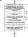
- the controller 140 may perform a method 300 of detecting a cyber-attack against one or more electrical distribution devices (e.g., the transformers 110, 112).
- the method 300 begins with block 302 in which the controller 140 determines whether to perform detection of cyber-attacks.
- the controller 140 may determine to proceed with performing detection of cyber-attacks if the controller 140 is in communication with one or more sensors 150 of the corresponding electrical distribution device to be monitored (e.g., the transformer 110) and has access to a mathematical model indicative of a relationship between operational parameters of the electrical distribution device (e.g., in the memory 214 of the controller 140).
- the controller 140 may determine whether to detect cyber-attacks based on other factors. Regardless, in response to a determination to detect cyber-attacks, the method 300 advances to block 304 in which the controller 140 determines one or more measured operational parameters of an electrical distribution device with one or more corresponding sensors (e.g., the sensors 150). In doing so, and as indicated in block 306, the controller 140 determines measured operational parameters of a transformer (e.g., the transformer 110). Further, and as indicated in block 308, in determining the measured operational parameters, the controller 140 receives, from the corresponding sensors (e.g., the sensors 150), a signal indicative of values of the corresponding operational parameters.
- the corresponding sensors e.g., the sensors 150
- the controller 140 may determine a measured electrical current of the electrical distribution device (e.g., the transformer 110). Additionally or alternatively, and as indicated in block 312, the controller 140 may determine a measured voltage of the electrical distribution device (e.g., the transformer 110). In some embodiments, the controller 140 may determine a magnitude and phase angle of an operational parameter of the electrical distribution device, as indicated in block 314. Additionally or alternatively, the controller 140 may determine a measured temperature of the electrical distribution device, as indicated in block 316. For example, and as indicated in block 318, the controller may determine an ambient temperature associated with the electrical distribution device.
- the controller 140 may also determine a coolant fluid temperature (e.g., a temperature of the coolant fluid in the coolant fluid tank 160). In doing so, the controller 140 may determine a coolant fluid temperature associated with the top of the coolant fluid tank 160, as indicated in block 322. The controller 140 may additionally or alternatively determine a coolant fluid temperature associated with the bottom of the coolant fluid tank 160, as indicated in block 324. As indicated in block 326, the controller 140 may determine a measured change or rate of change of operational parameters.
- a coolant fluid temperature e.g., a temperature of the coolant fluid in the coolant fluid tank 160. In doing so, the controller 140 may determine a coolant fluid temperature associated with the top of the coolant fluid tank 160, as indicated in block 322. The controller 140 may additionally or alternatively determine a coolant fluid temperature associated with the bottom of the coolant fluid tank 160, as indicated in block 324. As indicated in block 326, the controller 140 may determine a measured change or rate of change of operational parameters.
- the controller 140 may wait for one or more operational parameters to stabilize (e.g., for the rate of change to meet a predefined threshold, for a measured operational parameter to vary within a predefined range, etc.), as indicated in block 328. For example, and as indicated in block 330, the controller 140 may wait for the ambient temperature to stabilize.
- one or more operational parameters to stabilize e.g., for the rate of change to meet a predefined threshold, for a measured operational parameter to vary within a predefined range, etc.
- the method 300 advances to block 332 of FIG. 4 , in which the controller 140 determines an expected value of one or more operational parameters of the electrical distribution device (e.g., the transformer 110) from the measured operational parameters (e.g., from block 304) and a model indicative of a relationship between operational parameters of the electrical distribution device. In doing so, the controller 140 may determine an expected electrical current value, as indicated in block 334. Additionally or alternatively, the controller 140 may determine an expected voltage value, as indicated in block 336. As indicated in block 338, the controller 140 may determine an expected magnitude and phase angle of one or more operational parameters. Additionally or alternatively, the controller 140 may determine an expected temperature value, as indicated in block 340.
- the controller 140 determines an expected value of one or more operational parameters of the electrical distribution device (e.g., the transformer 110) from the measured operational parameters (e.g., from block 304) and a model indicative of a relationship between operational parameters of the electrical distribution device. In doing so, the controller 140 may determine an expected electrical current value, as indicated in block 334
- the controller 140 may determine an expected winding hot spot temperature. Additionally, the controller 140 may determine real time load losses as indicated in block 344. In some embodiments, the controller 140 may determine an expected power balance from an input bus and an output bus of the electrical distribution device (e.g., the transformer 110), as indicated in block 346. Further, and as indicated in block 348, the controller 140 may determine an expected change or rate of change of an operational parameter. In some embodiments, the controller 140 may determine a residual value, which may be embodied as a number indicative of an effect of noise on a measurement of an operational parameter of the electrical distribution device (e.g., the transformer 110). Subsequently, the method 300 advances to block 352 of FIG. 5 in which the controller determines whether one or more of the measured operational parameter(s) satisfy corresponding threshold value(s).
- the controller 140 may determine whether the operational parameter(s) satisfy a corresponding expected value (e.g., from block 332), as indicated in block 354. In some embodiments, the controller 140 may adjust the expected value (e.g., from block 332) as a function of a harmonic loss contribution, as indicated in block 356. In embodiments in which the controller 140 determines a residual value (e.g., in block 350), the controller 140 determines whether the residual value is within a predefined upper bound and lower bound (e.g., within an expected range), as indicated in block 358.
- the controller 140 may, in some embodiments, perform a comparison of the measured operational parameters to one or more threshold values over a predefined time interval, as indicated in block 360. In some embodiments, the controller 140 may compare a measured proportionality of input and output power and real time load losses, as indicated in block 362. Subsequently, in block 364, the controller 140 determines whether the threshold is satisfied. If so (e.g., a measured value is within a predefined range of a corresponding expected value), the method 300 loops back to block 302 in which the controller 140 determines whether to continue detection of cyber-attacks. Otherwise, the method 300 advances to block 366, in which the controller 140 performs a responsive action to a suspected cyber-attack.
- the controller 140 may generate an alert indicative of a suspected cyber-attack, as indicated in block 368. In doing so, the controller 140 may generate an alert that indicates the measured operational parameter does not satisfy the corresponding threshold, as indicated in block 370. As indicated in block 372, the controller 140 may generate an alert that indicates the amount by which the threshold is not satisfied (e.g., a measured temperature exceeds the expected temperature by 10 degrees, etc.). The alert may also identify the electrical distribution device to which the alert pertains (e.g., by a serial number, a media access control address (MAC), an internet protocol (IP) address, a geographical location, etc.), as indicated in block 374.
- MAC media access control address
- IP internet protocol
- the controller 140 may send the alert (e.g., data indicative of the alert) to a remote compute device (e.g., a compute device in the control system 120), as indicated in block 376. Additionally or alternatively, the controller 140 may display the alert in a user interface (e.g., with an HMI connected to the controller 140), as indicated in block 378. As indicated in block 380, the controller may perform a corrective action (e.g., by adjusting a tap changer setting, by deactivating the electrical distribution device to await inspection by a technician, etc.) to mitigate one or more effects of the suspected cyber-attack. Subsequently, the method 300 loops back to block 302 to again determine whether to continue detection of cyber-attacks.
- a corrective action e.g., by adjusting a tap changer setting, by deactivating the electrical distribution device to await inspection by a technician, etc.
- the controller 140 may utilize a static model 600 of a transformer (e.g., the transformer 110) with a tap changer connected between buses b and k.
- Potential cyber-attacks against the transformer 110 may include an attacker issuing a malicious control command to raise or lower the tap setting a km or an attacker injecting fabricated sensor measurements (e.g., a temperature of the coolant fluid and a load ratio).
- the result of the first type of attack may create an over or under voltage whereas the second type of attack may disrupt the transformer operation or condition-based estimations of the transformer's usable lifetime.
- the resulting model 700 is shown in FIG. 7 .
- the model may be integrated with the physical system around the transformer, such as a substation or larger system, as shown in the model 800 of FIG. 8 .
- the controller 140 may provide security against cyber-attacks based on transformer sensor measurements, such as electrical current and voltage.
- transformer sensor measurements such as electrical current and voltage.
- a cyber attacker may inject malicious (i.e., false) current and voltage measurements into the sensors 150 on each side of the transformer 110. More specifically, referring back to the model 800 of FIG. 8 , an attacker could corrupt both the voltage and current measurements at bus m.
- the controller 140 identifies the violation of one of the elements of the residual matrix as a potential cyber-attack.
- the controller 140 may further determine which measurement is falsified. In doing so, the controller 140 may apply the following rules. First, a falsification of the primary current measurement I km would cause the residuals d 1 and d 3 to exceed their corresponding thresholds. Second, a falsification of the secondary current measurement I mk would cause the residuals d 2 and d 3 to exceed their thresholds. Third, a falsification of the primary voltage measurement E k would cause the residuals d 1 and d 2 to exceed their thresholds. Fourth, a falsification of the secondary voltage measurement E m would cause the residuals d 1 and d 2 to exceed their thresholds.
- a transformer e.g., the transformer 110
- the controller 140 may provide security against cyber-attacks to the transformer 110 as described herein.
- Phase shifting transformers are typically used to control active power flows by changing the phase angle between the voltages across the transformer.
- a turns ratio t km is embodied as a ratio of the complex voltages E p and E k .
- the turns ratio is defined as a complex quantity with magnitude a km and angle ⁇ km .
- the controller 140 may apply the four rules described above to determine which measurement or measurements (e.g., the primary current E km , the secondary current I mk , the primary voltage E k , or the secondary voltage E m ) have been falsified in a cyber-attack.
- measurement or measurements e.g., the primary current E km , the secondary current I mk , the primary voltage E k , or the secondary voltage E m
- the controller 140 may provide security against cyber-attacks on sensor measurements using local complementary sensor confirmation. For example, in the attack scenario described above, confirmation of a change in the electrical current can be obtained by comparing the measurements of complementary sensors 150 (e.g., a temperature at the top of the coolant fluid tank and a temperature at the bottom of the coolant fluid tank 160). The controller 140 may also obtain one or more temperatures that are not directly measured, but instead are calculated from other temperatures. For example, the controller 140 may calculate a winding hot spot temperature in the transformer 110 as a function of temperature measurements from the top and/or bottom of the coolant fluid tank 160.
- complementary sensors 150 e.g., a temperature at the top of the coolant fluid tank and a temperature at the bottom of the coolant fluid tank 160.
- the controller 140 may also obtain one or more temperatures that are not directly measured, but instead are calculated from other temperatures.
- the controller 140 may calculate a winding hot spot temperature in the transformer 110 as a function of temperature measurements from the top and/or bottom of the coolant fluid tank 160.
- calculation of the winding hot spot temperature may depend on electrical current, ambient temperature, the type of cooling fluid, and physical parameters of the transformer provided from design calculations and/or test data. Other calculated temperature values may be provided from a combination of measured sensor data, subscribed information, and/or transformer physical properties.
- the controller 140 may provide an additional layer of security against cyber-attacks by verifying changes in related measured temperature values and calculated temperature values. Current-dependent calculated temperature values would be affected by falsified electrical current data while directly measured temperature values may not be falsified.
- a calculated value such as the winding hot spot temperature may be compared to the temperature at the top of the coolant fluid tank 160 in terms of either absolute temperature rise over a given time interval or an instantaneous rate of change with respect to the measurement time interval for the measured and calculated values.
- the controller 140 may utilize the following equations in such a process: T Rise , calc
- T Rise,calc and T Rise,meas represent generic related measured and calculated temperatures.
- the T Rise,calc also specifies a given per unit current, I pu , and ambient temperature, T a , for comparison purposes.
- the calculation is then dependent upon per unit current, I pu , and ambient temperature T a .
- the confirmation process based on local complementary sensors may include performing the evaluation over a variable time span, depending on the polling interval of temperature and current sensors (e.g., the sensors 150).
- a limit may be taken to express a set of temperature characteristics over an instantaneous timeframe, as follows: dT Rise , calc dt
- ⁇ H represents a calculated winding hotspot temperature at the present time instant
- ⁇ H,i represents a calculated winding hotspot temperature at a previous time instant
- ⁇ ⁇ H,R represents a hotspot differential temperature at rated load
- I pu represents per unit current
- ⁇ ⁇ H,exp represents a hotspot differential temperature exponent
- ⁇ w represents a hotspot time constant in minutes.
- the controller 140 additionally analyzes a harmonic content of the electrical current.
- the harmonic content is an additional component of the electrical current that has a frequency larger than that of the nominal current (e.g., 50 or 60 Hz) that sums together with the nominal or fundamental frequency component in terms of superposition.
- the frequencies are at integer multiples of the nominal or fundamental component.
- non-linearity of the system may lead to frequencies between the integer multiples.
- the harmonic components can contribute additional generated heat as certain types of losses within the transformer, such as eddy current losses, which are proportional to the square of the frequency.
- the controller 140 may apply a threshold of 5% total harmonic distortion, the ratio of fundamental current to other harmonic components.
- an additional factor for computation may be determined (e.g., pursuant to the Institute of Electrical and Electronics Engineers (IEEE) standard C57.110 or other related standards) such that the calculated temperature is scaled by the additional losses due to harmonics.
- IEEE Institute of Electrical and Electronics Engineers
- ⁇ g represents the adjusted winding hotspot rise over the temperature of the top of the coolant fluid tank 160 in degrees Celsius
- ⁇ g-R is the rated winding hotspot rise over the temperature of the top of the coolant fluid tank 160 in degrees Celsius
- P LL (pu) is the per unit power loss under load calculated with harmonic loss contribution
- P LL-R (pu) is the per unit loss under rated conditions.
- F HL is a defined harmonic loss factor for winding eddy current losses
- P EC-R is the per unit winding eddy current loss under rated conditions.
- the conditions of the above equations could be taken as the rate winding hotspot rise over the temperature of the top of the coolant fluid tank 160, ⁇ g-R .
- the controller 140 may determine a lifetime estimate of the transformer 110 (e.g., an estimate of the usable lifetime of the transformer 110). In such embodiments, the controller 140 performs a comparison of the calculated estimated lifetime over a given timespan to the measured temperature value for proportionality, instead of the generic calculated temperature. The controller 140 may also utilize threshold limits on estimated lifetime accrual within a given timespan, based on either future current and temperature rise limits or historical data.
- Faa expresses the output of an age acceleration factor or calculated lifetime estimate over a given time. It is important to note that the temperature measurement from a the sensors 150 may be sampled less frequently than the current or voltage measurements (e.g., intervals of several seconds for temperature versus intervals of several milliseconds for current and/or voltage). However, as cyber-attacks grow increasingly complex, the incubation or infiltration period of an attack may be days or weeks long.
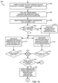
- the controller 140 may perform a method 1000 for detecting cyber-attacks based on local complementary sensor confirmation, using the operations described above.
- the method 1000 begins with block 1002, in which the controller 140 enables the algorithm after a temperature associated with the transformer 110 has stabilized under load conditions (e.g., the temperature varies by 4 degrees or less). Subsequently, the method 1000 advances to block 1004 in which the controller 140 obtains the measured temperature T meas (e.g., by polling the sensors 150) and corresponding calculated temperature(s), T calc . Afterwards, the controller 140 verifies a consistent ambient temperature (e.g., an average ambient temperature of less than 40 degrees Celsius), as indicated in block 1006.
- a consistent ambient temperature e.g., an average ambient temperature of less than 40 degrees Celsius
- the controller 140 determines whether a relatively high amount of harmonic distortion is present (e.g., greater than 5%). If so, the method 1000 advances to block 1010 in which the controller 140 calculates the contribution of harmonics to temperature rise. Subsequently, or if relatively high harmonics are not present, the method advances to concurrently perform blocks 1012 and 1016. In block 1012, the controller 140 calculates a rise of the measured temperature over a given time interval, or an instantaneous temperature rise. In block 1016, the controller 140 calculates a rise of calculated temperature values over a given time interval, or an instantaneous rise in the calculated temperature values.
- a relatively high amount of harmonic distortion is present (e.g., greater than 5%). If so, the method 1000 advances to block 1010 in which the controller 140 calculates the contribution of harmonics to temperature rise. Subsequently, or if relatively high harmonics are not present, the method advances to concurrently perform blocks 1012 and 1016. In block 1012, the controller 140 calculates a rise of the measured temperature over
- the controller 140 determines, in block 1014, whether the temperature rise is greater than zero and determines, in block 1018, whether the calculated temperature rise is greater than zero.
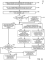
- the controller 140 combines the results of blocks 1014 and 1018 in block 1020 with an AND operation. That is, the controller 140 determines whether there was a change in both the measured temperature and the calculated temperature. If so, the method 1000 advances to block 1022 in which the controller 140 verifies the temperature change direction for the measured and calculated temperatures. Subsequently, the method 1000 advances to blocks 1024 and 1030 of FIG. 11 .
- the controller 140 determines whether both the measured temperature and the calculated temperature increased. If so, the method 1000 advances to block 1026, in which the controller 140 determines that a load current actually did increase. If not, the method 1000 advances to block 1028, in which the controller 140 generates an alarm indicative of an inconsistent load condition (e.g., a potential cyber-attack).
- block 1030 which may be performed concurrently with block 1024, the controller 140 determines whether the measured temperature and calculated temperature both decreased. If so, then the controller 140, in the illustrative embodiment, confirms that there was a load current decrease, as indicated in block 1032. Otherwise, or if the controller 140 determined in block 1020 that the measured temperature and the calculated temperature did not both change, the method advances to block 1034 in which the controller generates an alarm of an inconsistent load condition (e.g., a potential cyber-attack).
- an inconsistent load condition e.g., a potential cyber-attack
- the normal operating conditions are those in which load is applied to a transformer (e.g., the transformer 110) and a subsequent temperature rise is identified, due to rate current followed by an increase in the current over the rated conditions.
- I pu ,T a ⁇ H .
- an example attack scenario may involve an attacker causing falsified current measurements to be reported.
- the falsified current measurements 1410 in the plot 1400 indicate a current that would be expected under the rated load of the transformer. However, the transformer is actually in an overload condition, as indicated by the current values 1420.
- the purpose of the cyber-attack is to prevent the transformer from initiating a cooling process.
- Example thermal limits 1510, 1530 are given for both the measured temperature of the top of the coolant fluid tank 160 and the calculated winding hotspot temperature, based on standards for the given transformer insulation materials.
- the false injected current value 1410 is shown as an input to the calculated winding hotspot temperature 1520 and the relationship provided in equations (29) and (31) no longer remains true, due to the increase in the measured temperature 1540 while the calculated temperature 1520 remains unchanged.
- the output of the calculated temperature value will not change, while the measured output will increase, leading to the generation of an alarm condition indicating inconsistent load conditions.
- the controller 140 performs operations to secure a transformer against cyber-attacks in which temperature sensor measurements are faked.
- the output power of a transformer is less than its input power.
- the difference is the amount of power converted into heat by core loss, winding losses, and stray losses.
- a combination of radiation and convection dissipate the heat from the exposed surfaces of the transformer.
- P in ⁇ out m represents the measured proportionality of input and output power of the m th transformer at different points of temperature or load current and C oil temp m and C hotspot m indicate an official characteristic of input and output power of the m th transformer given by a measured temperature (e.g., from the sensors 150) or information provided by a weather service or other source.
- the transformer 110 may detect an abnormal behavior (e.g., a cyber-attack) if the measured proportion of input and output power is not consistent with the official characteristic, when the measured temperature of the transformer is normal (e.g., the expected temperature, given the present load).
- P LL represents real time load losses calculated from I2R or load losses, eddy current loses (P EC ), and other stray losses (P OSL ).
- the load losses are a function of the temperature-dependent winding resistance value (e.g., values defined in IEEE C57.12.90) and measured current.
- Eddy current and other stray losses are given as a function of a harmonic loss coefficient, such as defined in IEEE C57.111, and are dependent on load current.
- the characteristic temperature used in estimation of the real time losses can be determined from IEEE C57.91, IEC 60076-7, or a similar standard, from either ambient temperature or a characteristic coolant fluid temperature, as shown in equations (31) and (33).
- I ( ⁇ t ) is representative of the transformer load current for a given time interval
- ⁇ ambient is representative of the ambient temperature
- P NL,R is representative of rated no load losses at a specific ambient temperature (e.g., 75 C)
- P LL,R represents rated load losses calculated from I2R, eddy losses, and other stray losses.
- ⁇ oil ( ⁇ t ) is representative of the transformer oil temperature (i.e., the temperature of the coolant fluid) derived from measured top or bottom temperatures in the coolant fluid tank 160, or a top/bottom relationship equation.
- ⁇ hotspot ( ⁇ t ) is representative of the transformer hotspot temperature.
- the transformer 110 may perform a comparison of P in ⁇ out m and P total loss m within given tolerances to determine whether the power balance given from measured voltage and current values (e.g., from the sensors 150) match the total loss calculations from the measured temperature(s) and other dependencies.
- a method 1600 utilizing the above equations for detecting a cyber-attacks based on transformer temperature sensor measurements begins with block 1602, in which the controller 140 enables the algorithm after the temperature has stabilized to normal load conditions (e.g., the temperature varies by 4 degrees or less). Subsequently, the controller 140 determines the power balance (P in-out ) and characteristic temperature (C temp ) quantities, as indicated in block 1604. Afterwards, the controller 140 verifies that the ambient temperature associated with the transformer (e.g., the transformer 110) is consistent (e.g., that the ambient temperature has an average below 40 degrees Celsius), as indicated in block 1606.
- the ambient temperature associated with the transformer e.g., the transformer 110
- the ambient temperature has an average below 40 degrees Celsius
- the controller determines whether a relatively high amount of harmonic distortion (e.g., greater than 5%) is present. If so, the method 1600 proceeds to block 1610 in which the controller 140 calculates the contribution of the harmonics to the temperature rise, similar to block 1010 of FIG. 10 . Subsequently, or if the controller 140 determined in block 1608 that relatively high harmonic distortion is not present, the method 1600 advances to blocks 1612 and 1614, which the controller 140 may perform concurrently. In block 1612, the controller 140 calculates the expected power balance from the input and output buses. In block 1614, the controller 140 calculates the expected characteristic temperature of the coolant fluid in the coolant fluid tank 160 from measured temperatures (e.g., T oil and T ambient ).
- measured temperatures e.g., T oil and T ambient
- the controller 140 calculates the expected hotspot characteristic temperature from the coolant fluid temperature (e.g., the oil temperature T oil ). Further, in block 1618, the controller 140 calculates power total loss conditions using the given temperature. In block 1620, the controller 140 calculates the expected coolant fluid characteristic temperature from the ambient temperature, and in block 1622, the controller 140 calculates the expected hotspot characteristic temperature using the calculated expected coolant fluid characteristic temperature. Additionally, the controller 140 calculates the power total loss conditions at the given temperature, in block 1624. In block 1626, the controller 140 determines whether an equal power balances and power total loss is present. If so, the method 1600 advances to block 1628, in which the controller 140 confirms that consistent temperature measurements are present. Otherwise, the method 1600 advances to block 1630 in which the controller 140 generates an alarm indicative of inconsistent temperature measurements (e.g., a potential cyber-attack).
- the controller 140 determines whether an equal power balances and power total loss is present. If so, the method 1600 advances to block 1628, in which the controller 140 confirms that consistent temperature measurements are
Landscapes
- Engineering & Computer Science (AREA)
- Computer Security & Cryptography (AREA)
- Computer Hardware Design (AREA)
- General Engineering & Computer Science (AREA)
- Computing Systems (AREA)
- Computer Networks & Wireless Communication (AREA)
- Signal Processing (AREA)
- Physics & Mathematics (AREA)
- Software Systems (AREA)
- Theoretical Computer Science (AREA)
- General Physics & Mathematics (AREA)
- Artificial Intelligence (AREA)
- Evolutionary Computation (AREA)
- Mathematical Physics (AREA)
- Automation & Control Theory (AREA)
- Remote Monitoring And Control Of Power-Distribution Networks (AREA)
- Housings And Mounting Of Transformers (AREA)
Description
- The present application claims priority to
U.S. Utility Patent Application No. 15/963,850, entitled "TECHNOLOGIES FOR DETECTING CYBER-ATTACKS AGAINST ELECTRICAL DISTRIBUTION DEVICES," which was filed on April 26, 2018 - The use of industrial control systems (ICS) for controlling transformers in an electrical power grid is becoming more prevalent. Additionally, asset monitoring devices employing sensors for reporting voltage, current, temperature, dissolved gas or oil quality analysis, diminishment in the performance of components in the grid (e.g., bushing or tap changers), and other measurements are becoming more common for transformers. These monitoring devices are beginning to feed into automated substations to provide information about the overall condition of the transformers and their onboard components and to potentially prompt automated control actions. For example, it is becoming more common to utilize transformer tap changer controllers that are microprocessor-based and that have the ability to process remotely issued commands for changing the tap settings (e.g., commands submitted to the controller through a network). However, the ability to remotely (e.g., through a network) control the operations of a transformer may open the possibility of malicious commands (e.g., from a cyber attacker) being sent to and carried out by a transformer, potentially resulting in damage to the transformer and the electrical grid.
US 2014/0189860 A1 relates to devices, methods, and systems for control system cybersecurity.
US 2016/0118186 A1 relates to a hardened inductive device and systems and methods for protecting the inductive device from impact.
EP 2 033 060 A2 relates to a system for real-time optimization of power resources on an electrical system - The invention is defined in the independent claims. Advantageous features are described in the dependent claims.
- In one aspect, the present disclosure provides a method for securing a transformer. The method includes determining, by a controller of the transformer, a first measured value of a first operational parameter of the transformer based upon one or more signals received from one or more sensors of the transformer. The method also includes determining, by the controller, a second measured value of a second operational parameter of the transformer based upon one or more signals received from the one or more sensors of the transformer. Additionally, the method includes calculating, by the controller, a first expected value of the first operational parameter based on the second measured value of the second operational parameter and a model of the transformer that relates the first and second operational parameters. Further, the method includes comparing, by the controller, the first measured value of the first operational parameter to the first expected value of the first operational parameter and identifying, by the controller, when a difference between the first measured value and the first expected value exceeds a first threshold.
- In another aspect, the present disclosure provides a controller for securing a transformer. The controller includes circuitry to determine a first measured value of a first operational parameter of the transformer based upon one or more signals received from one or more sensors of the transformer. The circuitry is also to determine a second measured value of a second operational parameter of the transformer based upon one or more signals received from the one or more sensors of the transformer. Additionally, the circuitry is to calculate a first expected value of the first operational parameter based on the second measured value of the second operational parameter and a model of the transformer that relates the first and second operational parameters, compare the first measured value of the first operational parameter to the first expected value of the first operational parameter, and identify when a difference between the first measured value and the first expected value exceeds a first threshold.
- In yet another aspect, the present disclosure provides one or more machine-readable storage media having a plurality of instructions stored thereon that, in response to being executed, cause a controller to determine a first measured value of a first operational parameter of a transformer based upon one or more signals received from one or more sensors of the transformer. The instructions further cause the controller to determine a second measured value of a second operational parameter of the transformer based upon one or more signals received from the one or more sensors of the transformer, calculate a first expected value of the first operational parameter based on the second measured value of the second operational parameter and a model of the transformer that relates the first and second operational parameters, compare the first measured value of the first operational parameter to the first expected value of the first operational parameter, and identify when a difference between the first measured value and the first expected value exceeds a first threshold.
- The concepts described herein are illustrated by way of example and not by way of limitation in the accompanying figures. For simplicity and clarity of illustration, elements illustrated in the figures are not necessarily drawn to scale. Where considered appropriate, reference labels have been repeated among the figures to indicate corresponding or analogous elements. The detailed description particularly refers to the accompanying figures in which:
-
FIG. 1 is a simplified block diagram of at least one embodiment of a system for detecting cyber-attacks against electrical distribution devices; -
FIG. 2 is a simplified block diagram of at least one embodiment of a controller of the system ofFIG. 1 ; -
FIGS. 3-5 are a simplified block diagram of at least one embodiment of a method for detecting cyber-attacks that may be performed by the controller ofFIGS. 1 and2 ; -
FIGS. 6-9 are simplified diagrams of transformer models that may be utilized by the controller ofFIGS. 1 and2 to detect cyber-attacks; -
FIGS. 10-11 are a simplified diagram of at least one embodiment of a method for detecting cyber-attacks based on local complementary sensor confirmation that may be performed by the controller ofFIGS. 1 and2 ; -
FIGS. 12-13 are plots of a change in the load of a transformer and a corresponding change in temperature of the transformer; -
FIGS. 14-15 are plots of a change in the load of a transformer and a temperature rise difference between calculated and measured temperature values; and -
FIG. 16 is a simplified flow diagram of at least one embodiment of a method for detecting a cyber-attacks based on transformer temperature sensor measurements. - While the concepts of the present disclosure are susceptible to various modifications and alternative forms, specific embodiments thereof have been shown by way of example in the drawings and will be described herein in detail. It should be understood, however, that there is no intent to limit the concepts of the present disclosure to the particular forms disclosed, but on the contrary, the intention is to cover all modifications, equivalents, and alternatives consistent with the present disclosure and the appended claims.
- References in the specification to "one embodiment," "an embodiment," "an illustrative embodiment," etc., indicate that the embodiment described may include a particular feature, structure, or characteristic, but every embodiment may or may not necessarily include that particular feature, structure, or characteristic. Moreover, such phrases are not necessarily referring to the same embodiment. Further, when a particular feature, structure, or characteristic is described in connection with an embodiment, it is submitted that it is within the knowledge of one skilled in the art to effect such feature, structure, or characteristic in connection with other embodiments whether or not explicitly described. Additionally, it should be appreciated that items included in a list in the form of "at least one A, B, and C" can mean (A); (B); (C); (A and B); (A and C); (B and C); or (A, B, and C). Similarly, items listed in the form of "at least one of A, B, or C" can mean (A); (B); (C); (A and B); (A and C); (B and C); or (A, B, and C).
- The disclosed embodiments may be implemented, in some cases, in hardware, firmware, software, or any combination thereof. The disclosed embodiments may also be implemented as instructions carried by or stored on a transitory or non-transitory machine-readable (e.g., computer-readable) storage medium, which may be read and executed by one or more processors. A machine-readable storage medium may be embodied as any storage device, mechanism, or other physical structure for storing or transmitting information in a form readable by a machine (e.g., a volatile or non-volatile memory, a media disc, or other media device).
- In the drawings, some structural or method features may be shown in specific arrangements and/or orderings. However, it should be appreciated that such specific arrangements and/or orderings may not be required. Rather, in some embodiments, such features may be arranged in a different manner and/or order than shown in the illustrative figures. Additionally, the inclusion of a structural or method feature in a particular figure is not meant to imply that such feature is required in all embodiments and, in some embodiments, may not be included or may be combined with other features.
- Referring now to
FIG. 1 , asystem 100 for detecting cyber-attacks against electrical distribution devices includes a set of transformers (i.e., electrical distribution devices) 110, 112, each of which may provide electricity to one or more other devices (not shown), and a control system 120 (e.g., an industrial control system) communicatively coupled to thetransformers network 130. As used herein, the term "electrical distribution" includes both electrical transmission devices and electrical distribution devices, and the corresponding power levels. Eachtransformer sensors transformer transformer transformer coolant fluid tank 160, 162 which may be embodied as a container of a fluid (e.g., oil) used to cool one or more components of thecorresponding transformer controller 140, which may be included in eachtransformer control system 120 obtains measurements, from thesensors corresponding transformer system 100 may provide improved security against cyber-attacks as compared to typical electrical distribution systems. - Referring now to
FIG. 2 , thecontroller 140 may be embodied as any type of device (e.g., a computer) capable of performing the functions described herein, including determining a first measured value of a first operational parameter of the transformer based upon one or more signals received from one or more sensors of the transformer, determining a second measured value of a second operational parameter of the transformer based upon one or more signals received from the one or more sensors of the transformer, calculating a first expected value of the first operational parameter based on the second measured value of the second operational parameter and a model of the transformer that relates the first and second operational parameters, comparing the first measured value of the first operational parameter to the first expected value of the first operational parameter, and identifying when a difference between the first measured value and the first expected value exceeds a first threshold. - As shown in
FIG. 2 , theillustrative controller 140 includes acompute engine 210, an input/output (I/O)subsystem 216,communication circuitry 218, and one or moredata storage devices 224. Of course, in other embodiments, thecontroller 140 may include other or additional components, such as those commonly found in a computer (e.g., display, peripheral devices, etc.). Additionally, in some embodiments, one or more of the illustrative components may be incorporated in, or otherwise form a portion of, another component. - The
compute engine 210 may be embodied as any type of device or collection of devices capable of performing various compute functions described below. In some embodiments, thecompute engine 210 may be embodied as a single device such as an integrated circuit, an embedded system, a field-programmable gate array (FPGA), a system-on-a-chip (SOC), or other integrated system or device. Additionally, in some embodiments, thecompute engine 210 includes or is embodied as aprocessor 212 and amemory 214. Theprocessor 212 may be embodied as any type of processor capable of performing the functions described herein. For example, theprocessor 212 may be embodied as a microcontroller, a single or multi-core processor(s), or other processor or processing/controlling circuit. In some embodiments, theprocessor 212 may be embodied as, include, or be coupled to an FPGA, an application specific integrated circuit (ASIC), reconfigurable hardware or hardware circuitry, or other specialized hardware to facilitate performance of the functions described herein. - The
main memory 214 may be embodied as any type of volatile (e.g., dynamic random access memory (DRAM), etc.) or non-volatile memory or data storage capable of performing the functions described herein. Volatile memory may be a storage medium that requires power to maintain the state of data stored by the medium. In some embodiments, all or a portion of themain memory 214 may be integrated into theprocessor 212. In operation, themain memory 214 may store various software and data used during operation such as operational parameters of atransformer transformer - The
compute engine 210 is communicatively coupled to other components of thecontroller 140 via the I/O subsystem 216, which may be embodied as circuitry and/or components to facilitate input/output operations with the compute engine 210 (e.g., with theprocessor 212 and/or the main memory 214) and other components of thecontroller 140. For example, the I/O subsystem 216 may be embodied as, or otherwise include, memory controller hubs, input/output control hubs, integrated sensor hubs, firmware devices, communication links (e.g., point-to-point links, bus links, wires, cables, light guides, printed circuit board traces, etc.), and/or other components and subsystems to facilitate the input/output operations. In some embodiments, the I/O subsystem 216 may form a portion of a system-on-a-chip (SoC) and be incorporated, along with one or more of theprocessor 212, themain memory 214, and other components of thecontroller 140, into thecompute engine 210. - The
communication circuitry 218 may be embodied as any communication circuit, device, or collection thereof, capable of enabling communications over thenetwork 130 between thecontroller 140 and another compute device (e.g., one or more compute devices in thecontrol system 120, etc.). Thecommunication circuitry 218 may be configured to use any one or more communication technology (e.g., wired or wireless communications) and associated protocols (e.g., Ethernet, Bluetooth®, Wi-Fi®, WiMAX, etc.) to effect such communication. - The
illustrative communication circuitry 218 includes a network interface controller (NIC) 210. TheNIC 220 may be embodied as one or more add-in-boards, daughter cards, network interface cards, controller chips, chipsets, or other devices that may be used by thecontroller 140 to connect with another compute device (e.g., one or more compute devices in thecontrol system 120, etc.). In some embodiments, theNIC 220 may be embodied as part of a system-on-a-chip (SoC) that includes one or more processors, or included on a multichip package that also contains one or more processors. In some embodiments, theNIC 220 may include a local processor (not shown) and/or a local memory (not shown) that are both local to theNIC 220. In such embodiments, the local processor of theNIC 220 may be capable of performing one or more of the functions of thecompute engine 210 described herein. Additionally or alternatively, in such embodiments, the local memory of theNIC 220 may be integrated into one or more components of thecontroller 140 at the board level, socket level, chip level, and/or other levels. - The one or
more sensors 222 may be embodied as any type of devices configured to measure and report operational parameters of acorresponding transformer sensors 222 may include one or more temperature sensors capable of measuring cooling fluid temperatures at one or more locations in thetransformer - The one or more illustrative
data storage devices 224, may be embodied as any type of devices configured for short-term or long-term storage of data such as, for example, memory devices and circuits, memory cards, hard disk drives, solid-state drives, or other data storage devices. Eachdata storage device 224 may include a system partition that stores data and firmware code for thedata storage device 224. Eachdata storage device 224 may also include an operating system partition that stores data files and executables for an operating system. - Additionally or alternatively, the
controller 140 may include one or moreperipheral devices 226. Suchperipheral devices 226 may include any type of peripheral device commonly found in a compute device such as a display or other output device and/or one more input devices, such as a touchscreen or buttons, forming a human-machine interface (HMI). Additionally, theperipheral devices 226 may include other components, such as a tap changer, for controlling operations of thecorresponding transformer - As described above, the
transformers control system 120 are illustratively in communication via thenetwork 130, which may be embodied as any type of wired or wireless communication network, including global networks (e.g., the Internet), local area networks (LANs) or wide area networks (WANs), cellular networks (e.g., Global System for Mobile Communications (GSM), 3G, Long Term Evolution (LTE), Worldwide Interoperability for Microwave Access (WiMAX), etc.), digital subscriber line (DSL) networks, cable networks (e.g., coaxial networks, fiber networks, etc.), or any combination thereof. - Referring now to
FIG. 3 , thecontroller 140, in operation, may perform amethod 300 of detecting a cyber-attack against one or more electrical distribution devices (e.g., thetransformers 110, 112). In the illustrative embodiment, themethod 300 begins withblock 302 in which thecontroller 140 determines whether to perform detection of cyber-attacks. In the illustrative embodiment, thecontroller 140 may determine to proceed with performing detection of cyber-attacks if thecontroller 140 is in communication with one ormore sensors 150 of the corresponding electrical distribution device to be monitored (e.g., the transformer 110) and has access to a mathematical model indicative of a relationship between operational parameters of the electrical distribution device (e.g., in thememory 214 of the controller 140). In other embodiments, thecontroller 140 may determine whether to detect cyber-attacks based on other factors. Regardless, in response to a determination to detect cyber-attacks, themethod 300 advances to block 304 in which thecontroller 140 determines one or more measured operational parameters of an electrical distribution device with one or more corresponding sensors (e.g., the sensors 150). In doing so, and as indicated inblock 306, thecontroller 140 determines measured operational parameters of a transformer (e.g., the transformer 110). Further, and as indicated inblock 308, in determining the measured operational parameters, thecontroller 140 receives, from the corresponding sensors (e.g., the sensors 150), a signal indicative of values of the corresponding operational parameters. As indicated inblock 310, thecontroller 140 may determine a measured electrical current of the electrical distribution device (e.g., the transformer 110). Additionally or alternatively, and as indicated inblock 312, thecontroller 140 may determine a measured voltage of the electrical distribution device (e.g., the transformer 110). In some embodiments, thecontroller 140 may determine a magnitude and phase angle of an operational parameter of the electrical distribution device, as indicated inblock 314. Additionally or alternatively, thecontroller 140 may determine a measured temperature of the electrical distribution device, as indicated inblock 316. For example, and as indicated inblock 318, the controller may determine an ambient temperature associated with the electrical distribution device. As indicated inblock 320, thecontroller 140 may also determine a coolant fluid temperature (e.g., a temperature of the coolant fluid in the coolant fluid tank 160). In doing so, thecontroller 140 may determine a coolant fluid temperature associated with the top of the coolant fluid tank 160, as indicated inblock 322. Thecontroller 140 may additionally or alternatively determine a coolant fluid temperature associated with the bottom of the coolant fluid tank 160, as indicated inblock 324. As indicated in block 326, thecontroller 140 may determine a measured change or rate of change of operational parameters. In some embodiments, before proceeding to the next operations in themethod 300, thecontroller 140 may wait for one or more operational parameters to stabilize (e.g., for the rate of change to meet a predefined threshold, for a measured operational parameter to vary within a predefined range, etc.), as indicated in block 328. For example, and as indicated in block 330, thecontroller 140 may wait for the ambient temperature to stabilize. - Subsequently, the
method 300 advances to block 332 ofFIG. 4 , in which thecontroller 140 determines an expected value of one or more operational parameters of the electrical distribution device (e.g., the transformer 110) from the measured operational parameters (e.g., from block 304) and a model indicative of a relationship between operational parameters of the electrical distribution device. In doing so, thecontroller 140 may determine an expected electrical current value, as indicated inblock 334. Additionally or alternatively, thecontroller 140 may determine an expected voltage value, as indicated inblock 336. As indicated inblock 338, thecontroller 140 may determine an expected magnitude and phase angle of one or more operational parameters. Additionally or alternatively, thecontroller 140 may determine an expected temperature value, as indicated inblock 340. For example, and as indicated inblock 342, thecontroller 140 may determine an expected winding hot spot temperature. Additionally, thecontroller 140 may determine real time load losses as indicated inblock 344. In some embodiments, thecontroller 140 may determine an expected power balance from an input bus and an output bus of the electrical distribution device (e.g., the transformer 110), as indicated inblock 346. Further, and as indicated inblock 348, thecontroller 140 may determine an expected change or rate of change of an operational parameter. In some embodiments, thecontroller 140 may determine a residual value, which may be embodied as a number indicative of an effect of noise on a measurement of an operational parameter of the electrical distribution device (e.g., the transformer 110). Subsequently, themethod 300 advances to block 352 ofFIG. 5 in which the controller determines whether one or more of the measured operational parameter(s) satisfy corresponding threshold value(s). - Referring now to
FIG. 5 , in determining whether one or more of the measured operational parameter(s) satisfy corresponding threshold value(s), thecontroller 140 may determine whether the operational parameter(s) satisfy a corresponding expected value (e.g., from block 332), as indicated inblock 354. In some embodiments, thecontroller 140 may adjust the expected value (e.g., from block 332) as a function of a harmonic loss contribution, as indicated inblock 356. In embodiments in which thecontroller 140 determines a residual value (e.g., in block 350), thecontroller 140 determines whether the residual value is within a predefined upper bound and lower bound (e.g., within an expected range), as indicated inblock 358. Thecontroller 140 may, in some embodiments, perform a comparison of the measured operational parameters to one or more threshold values over a predefined time interval, as indicated inblock 360. In some embodiments, thecontroller 140 may compare a measured proportionality of input and output power and real time load losses, as indicated inblock 362. Subsequently, inblock 364, thecontroller 140 determines whether the threshold is satisfied. If so (e.g., a measured value is within a predefined range of a corresponding expected value), themethod 300 loops back to block 302 in which thecontroller 140 determines whether to continue detection of cyber-attacks. Otherwise, themethod 300 advances to block 366, in which thecontroller 140 performs a responsive action to a suspected cyber-attack. - In performing a responsive action, the
controller 140 may generate an alert indicative of a suspected cyber-attack, as indicated inblock 368. In doing so, thecontroller 140 may generate an alert that indicates the measured operational parameter does not satisfy the corresponding threshold, as indicated inblock 370. As indicated inblock 372, thecontroller 140 may generate an alert that indicates the amount by which the threshold is not satisfied (e.g., a measured temperature exceeds the expected temperature by 10 degrees, etc.). The alert may also identify the electrical distribution device to which the alert pertains (e.g., by a serial number, a media access control address (MAC), an internet protocol (IP) address, a geographical location, etc.), as indicated inblock 374. Thecontroller 140 may send the alert (e.g., data indicative of the alert) to a remote compute device (e.g., a compute device in the control system 120), as indicated inblock 376. Additionally or alternatively, thecontroller 140 may display the alert in a user interface (e.g., with an HMI connected to the controller 140), as indicated inblock 378. As indicated inblock 380, the controller may perform a corrective action (e.g., by adjusting a tap changer setting, by deactivating the electrical distribution device to await inspection by a technician, etc.) to mitigate one or more effects of the suspected cyber-attack. Subsequently, themethod 300 loops back to block 302 to again determine whether to continue detection of cyber-attacks. - Referring now to
FIG. 6 , thecontroller 140 may utilize astatic model 600 of a transformer (e.g., the transformer 110) with a tap changer connected between buses b and k. Potential cyber-attacks against thetransformer 110 may include an attacker issuing a malicious control command to raise or lower the tap setting akm or an attacker injecting fabricated sensor measurements (e.g., a temperature of the coolant fluid and a load ratio). The result of the first type of attack may create an over or under voltage whereas the second type of attack may disrupt the transformer operation or condition-based estimations of the transformer's usable lifetime. Themodel 600 can be converted to a "pi" model with constants A, B, and C using the following equations:


- The resulting
model 700 is shown inFIG. 7 . Further, the model may be integrated with the physical system around the transformer, such as a substation or larger system, as shown in themodel 800 ofFIG. 8 . - In some embodiments, as described above, the
controller 140 may provide security against cyber-attacks based on transformer sensor measurements, such as electrical current and voltage. For example, a cyber attacker may inject malicious (i.e., false) current and voltage measurements into thesensors 150 on each side of thetransformer 110. More specifically, referring back to themodel 800 ofFIG. 8 , an attacker could corrupt both the voltage and current measurements at bus m. To guard against such an attack, thecontroller 140 may test the consistency of the measurements with the performance equations of thetransformer 110. The relationship between the voltages and currents can be expressed as follows:

- Provided that there is no fault within the
transformer 110, the algebraic sum of both the primary and secondary currents is theoretically equal to zero, as shown in the following equation:
- In practice, equations (4)-(6) will not be satisfied due to the presence of noise in the measurements and minor changes to the transformer parameters. As such, the
controller 140 may calculate residual quantities representing the mismatches according to the following equations:


- The relationships of equations (7)-(9) may be expressed in the following matrix relationship:

- Further, the
controller 140 may set thresholds for the residual values that define the maximum acceptable values for the residuals (e.g., an upper bound and a lower bound), as follows:
- An attack on one of the measurements would appear as a violation of the thresholds (e.g., the measurements would fall outside the upper and lower bounds). More specifically, one or more of the elements would exceed the corresponding threshold according to the following equation:

- The
controller 140, in such embodiments, identifies the violation of one of the elements of the residual matrix as a potential cyber-attack. Thecontroller 140 may further determine which measurement is falsified. In doing so, thecontroller 140 may apply the following rules. First, a falsification of the primary current measurement Ikm would cause the residuals d1 and d3 to exceed their corresponding thresholds. Second, a falsification of the secondary current measurement Imk would cause the residuals d2 and d3 to exceed their thresholds. Third, a falsification of the primary voltage measurement Ek would cause the residuals d1 and d2 to exceed their thresholds. Fourth, a falsification of the secondary voltage measurement Em would cause the residuals d1 and d2 to exceed their thresholds. - In embodiments in which a transformer (e.g., the transformer 110) is a phase shifting transformer, the
controller 140 may provide security against cyber-attacks to thetransformer 110 as described herein. Phase shifting transformers are typically used to control active power flows by changing the phase angle between the voltages across the transformer. Referring now toFIG. 9 , in amodel 900 that may be utilized by thecontroller 140 to detect a cyber-attack against thetransformer 110, a turns ratio tkm is embodied as a ratio of the complex voltages Ep and Ek. The turns ratio is defined as a complex quantity with magnitude akm and angle ϕkm. As such, the complex voltage at an internal point p is expressed in the following equation:
- Accordingly, the angle of the voltage at point p is shifted by the phase angle of the transformer as follows:


- The physical relationship of the primary and secondary currents may be expressed in terms of the complex terms ratio, as follows:

- The currents may be expressed in terms of the voltages and the impedance of the transformer as follows:


- The currents can also be expressed in terms of the terminal voltages of the
transformer 110, as follows:


- The equations (21)-(23) may be expressed in matrix form, as follows:

- The
controller 140 may apply thresholds (e.g., upper and lower bounds) for the residual values as follows:
- A falsification of the measurements would result in a violation of threshold values. More specifically, one or more of the elements d1, d2, or d3 would exceed its corresponding threshold, as follows:

- Accordingly, the
controller 140 may apply the four rules described above to determine which measurement or measurements (e.g., the primary current Ekm, the secondary current Imk, the primary voltage Ek, or the secondary voltage Em) have been falsified in a cyber-attack. - In some embodiments, the
controller 140 may provide security against cyber-attacks on sensor measurements using local complementary sensor confirmation. For example, in the attack scenario described above, confirmation of a change in the electrical current can be obtained by comparing the measurements of complementary sensors 150 (e.g., a temperature at the top of the coolant fluid tank and a temperature at the bottom of the coolant fluid tank 160). Thecontroller 140 may also obtain one or more temperatures that are not directly measured, but instead are calculated from other temperatures. For example, thecontroller 140 may calculate a winding hot spot temperature in thetransformer 110 as a function of temperature measurements from the top and/or bottom of the coolant fluid tank 160. For fluid-cooled transformers, calculation of the winding hot spot temperature may depend on electrical current, ambient temperature, the type of cooling fluid, and physical parameters of the transformer provided from design calculations and/or test data. Other calculated temperature values may be provided from a combination of measured sensor data, subscribed information, and/or transformer physical properties. Thecontroller 140 may provide an additional layer of security against cyber-attacks by verifying changes in related measured temperature values and calculated temperature values. Current-dependent calculated temperature values would be affected by falsified electrical current data while directly measured temperature values may not be falsified. Accordingly, a calculated value such as the winding hot spot temperature may be compared to the temperature at the top of the coolant fluid tank 160 in terms of either absolute temperature rise over a given time interval or an instantaneous rate of change with respect to the measurement time interval for the measured and calculated values. Thecontroller 140 may utilize the following equations in such a process:
- In the above equation, TRise,calc and TRise,meas represent generic related measured and calculated temperatures. The TRise,calc also specifies a given per unit current, Ipu, and ambient temperature, Ta , for comparison purposes. The calculation is then dependent upon per unit current, Ipu, and ambient temperature Ta. The confirmation process based on local complementary sensors may include performing the evaluation over a variable time span, depending on the polling interval of temperature and current sensors (e.g., the sensors 150). Alternatively, a limit may be taken to express a set of temperature characteristics over an instantaneous timeframe, as follows:

- An example of the above relationship is given as follows for the proportional relationship between a calculated winding hotspot temperature, TRise,calc | Ipu, Ta = ΘH, and a measured temperature, TRise,meas = ΘTO from the top of the coolant fluid tank 160:


- In the above equations, ΘH represents a calculated winding hotspot temperature at the present time instant, ΘH,i represents a calculated winding hotspot temperature at a previous time instant, ΔΘH,R represents a hotspot differential temperature at rated load, Ipu represents per unit current, ΔΘH,exp represents a hotspot differential temperature exponent, and τ w represents a hotspot time constant in minutes.
- In some embodiments, the
controller 140 additionally analyzes a harmonic content of the electrical current. The harmonic content is an additional component of the electrical current that has a frequency larger than that of the nominal current (e.g., 50 or 60 Hz) that sums together with the nominal or fundamental frequency component in terms of superposition. Typically, the frequencies are at integer multiples of the nominal or fundamental component. However, non-linearity of the system may lead to frequencies between the integer multiples. The harmonic components can contribute additional generated heat as certain types of losses within the transformer, such as eddy current losses, which are proportional to the square of the frequency. In some embodiments, thecontroller 140 may apply a threshold of 5% total harmonic distortion, the ratio of fundamental current to other harmonic components. That is, if harmonics are above the threshold, an additional factor for computation may be determined (e.g., pursuant to the Institute of Electrical and Electronics Engineers (IEEE) standard C57.110 or other related standards) such that the calculated temperature is scaled by the additional losses due to harmonics. An example calculation for winding hotspot rise over the temperature of the top of the coolant fluid tank 160 is given below:

- In the above equations, Θg represents the adjusted winding hotspot rise over the temperature of the top of the coolant fluid tank 160 in degrees Celsius, Θg-R is the rated winding hotspot rise over the temperature of the top of the coolant fluid tank 160 in degrees Celsius, PLL(pu) is the per unit power loss under load calculated with harmonic loss contribution, and PLL-R(pu) is the per unit loss under rated conditions. Additionally, FHL is a defined harmonic loss factor for winding eddy current losses and PEC-R is the per unit winding eddy current loss under rated conditions. Here, the conditions of the above equations could be taken as the rate winding hotspot rise over the temperature of the top of the coolant fluid tank 160, Θg-R.
- In other embodiments, the
controller 140 may determine a lifetime estimate of the transformer 110 (e.g., an estimate of the usable lifetime of the transformer 110). In such embodiments, thecontroller 140 performs a comparison of the calculated estimated lifetime over a given timespan to the measured temperature value for proportionality, instead of the generic calculated temperature. Thecontroller 140 may also utilize threshold limits on estimated lifetime accrual within a given timespan, based on either future current and temperature rise limits or historical data. This alternative condition is expressed as follows in terms of both an instantaneous or absolute time interval approach:

- In the above equations, Faa expresses the output of an age acceleration factor or calculated lifetime estimate over a given time. It is important to note that the temperature measurement from a the
sensors 150 may be sampled less frequently than the current or voltage measurements (e.g., intervals of several seconds for temperature versus intervals of several milliseconds for current and/or voltage). However, as cyber-attacks grow increasingly complex, the incubation or infiltration period of an attack may be days or weeks long. - Referring now to
FIG. 10 , thecontroller 140 may perform amethod 1000 for detecting cyber-attacks based on local complementary sensor confirmation, using the operations described above. In the illustrative embodiment, themethod 1000 begins withblock 1002, in which thecontroller 140 enables the algorithm after a temperature associated with thetransformer 110 has stabilized under load conditions (e.g., the temperature varies by 4 degrees or less). Subsequently, themethod 1000 advances to block 1004 in which thecontroller 140 obtains the measured temperature Tmeas (e.g., by polling the sensors 150) and corresponding calculated temperature(s), Tcalc. Afterwards, thecontroller 140 verifies a consistent ambient temperature (e.g., an average ambient temperature of less than 40 degrees Celsius), as indicated inblock 1006. Inblock 1008, thecontroller 140 determines whether a relatively high amount of harmonic distortion is present (e.g., greater than 5%). If so, themethod 1000 advances to block 1010 in which thecontroller 140 calculates the contribution of harmonics to temperature rise. Subsequently, or if relatively high harmonics are not present, the method advances to concurrently performblocks block 1012, thecontroller 140 calculates a rise of the measured temperature over a given time interval, or an instantaneous temperature rise. Inblock 1016, thecontroller 140 calculates a rise of calculated temperature values over a given time interval, or an instantaneous rise in the calculated temperature values. Subsequently, thecontroller 140 determines, inblock 1014, whether the temperature rise is greater than zero and determines, inblock 1018, whether the calculated temperature rise is greater than zero. Thecontroller 140 combines the results ofblocks block 1020 with an AND operation. That is, thecontroller 140 determines whether there was a change in both the measured temperature and the calculated temperature. If so, themethod 1000 advances to block 1022 in which thecontroller 140 verifies the temperature change direction for the measured and calculated temperatures. Subsequently, themethod 1000 advances toblocks FIG. 11 . - Referring now to
FIG. 11 , inblock 1024, thecontroller 140 determines whether both the measured temperature and the calculated temperature increased. If so, themethod 1000 advances to block 1026, in which thecontroller 140 determines that a load current actually did increase. If not, themethod 1000 advances to block 1028, in which thecontroller 140 generates an alarm indicative of an inconsistent load condition (e.g., a potential cyber-attack). Inblock 1030, which may be performed concurrently withblock 1024, thecontroller 140 determines whether the measured temperature and calculated temperature both decreased. If so, then thecontroller 140, in the illustrative embodiment, confirms that there was a load current decrease, as indicated inblock 1032. Otherwise, or if thecontroller 140 determined inblock 1020 that the measured temperature and the calculated temperature did not both change, the method advances to block 1034 in which the controller generates an alarm of an inconsistent load condition (e.g., a potential cyber-attack). - Referring now to
FIGS. 12 and 13 , a normal operating condition and a condition where falsified current may be detected by thecontroller 140 are shown. The normal operating conditions are those in which load is applied to a transformer (e.g., the transformer 110) and a subsequent temperature rise is identified, due to rate current followed by an increase in the current over the rated conditions. The temperature rise is reflected both in the temperature 1340 at the top of the coolant fluid tank 160, TRise,meas = ΘTO and the calculated winding hotspot temperature 1320, TRise,calc | Ipu,Ta = ΘH. The relationship follows equations (29) and (31), in which a standard defined rise over the temperature at the top of the coolant fluid tank 160 is calculated by thecontroller 140 to provide an estimated temperature of the winding hotspot. As shown in the plot 1200 ofFIG. 12 , the current 1210 has risen over time, resulting in the increased measured and calculated temperatures in the plot 1300 ofFIG. 13 . - Referring now to
FIGS. 14 and 15 , an example attack scenario may involve an attacker causing falsified current measurements to be reported. The falsifiedcurrent measurements 1410 in theplot 1400 indicate a current that would be expected under the rated load of the transformer. However, the transformer is actually in an overload condition, as indicated by thecurrent values 1420. As such, the purpose of the cyber-attack is to prevent the transformer from initiating a cooling process. Examplethermal limits current value 1410 is shown as an input to the calculated windinghotspot temperature 1520 and the relationship provided in equations (29) and (31) no longer remains true, due to the increase in the measuredtemperature 1540 while the calculatedtemperature 1520 remains unchanged. When evaluating the above logic with the provided attack scenario, the output of the calculated temperature value will not change, while the measured output will increase, leading to the generation of an alarm condition indicating inconsistent load conditions. - In some embodiments, the
controller 140 performs operations to secure a transformer against cyber-attacks in which temperature sensor measurements are faked. Normally, the output power of a transformer is less than its input power. Generally, the difference is the amount of power converted into heat by core loss, winding losses, and stray losses. A combination of radiation and convection dissipate the heat from the exposed surfaces of the transformer. As such, thecontroller 140, in some embodiments, may check the consistency of the characteristic temperature measurements with the input and output power of the transformer (e.g., the transformer 110), based on the following equations:


- In the above equations,


transformer 110 may detect an abnormal behavior (e.g., a cyber-attack) if the measured proportion of input and output power is not consistent with the official characteristic, when the measured temperature of the transformer is normal (e.g., the expected temperature, given the present load). As an example, the total losses of the system can be expressed as follows:

- In the above equations, PLL represents real time load losses calculated from I2R or load losses, eddy current loses (PEC), and other stray losses (POSL). The load losses are a function of the temperature-dependent winding resistance value (e.g., values defined in IEEE C57.12.90) and measured current. Eddy current and other stray losses are given as a function of a harmonic loss coefficient, such as defined in IEEE C57.111, and are dependent on load current. The characteristic temperature used in estimation of the real time losses can be determined from IEEE C57.91, IEC 60076-7, or a similar standard, from either ambient temperature or a characteristic coolant fluid temperature, as shown in equations (31) and (33). The following equations represent a set of example power-dependent temperature characteristics, according to IEEE C57.91, from ambient temperature:


- In the above equations, I(Δt) is representative of the transformer load current for a given time interval, Θ ambient is representative of the ambient temperature, PNL,R is representative of rated no load losses at a specific ambient temperature (e.g., 75 C), and PLL,R represents rated load losses calculated from I2R, eddy losses, and other stray losses. One output is τoil (Δt), which is representative of the transformer oil temperature (i.e., the temperature of the coolant fluid) derived from measured top or bottom temperatures in the coolant fluid tank 160, or a top/bottom relationship equation. Another output is τhotspot (Δt), which is representative of the transformer hotspot temperature. The
transformer 110 may perform a comparison of

- Referring now to
FIG. 16 , amethod 1600 utilizing the above equations for detecting a cyber-attacks based on transformer temperature sensor measurements begins withblock 1602, in which thecontroller 140 enables the algorithm after the temperature has stabilized to normal load conditions (e.g., the temperature varies by 4 degrees or less). Subsequently, thecontroller 140 determines the power balance (Pin-out) and characteristic temperature (Ctemp) quantities, as indicated inblock 1604. Afterwards, thecontroller 140 verifies that the ambient temperature associated with the transformer (e.g., the transformer 110) is consistent (e.g., that the ambient temperature has an average below 40 degrees Celsius), as indicated inblock 1606. Inblock 1608, the controller determines whether a relatively high amount of harmonic distortion (e.g., greater than 5%) is present. If so, themethod 1600 proceeds to block 1610 in which thecontroller 140 calculates the contribution of the harmonics to the temperature rise, similar to block 1010 ofFIG. 10 . Subsequently, or if thecontroller 140 determined inblock 1608 that relatively high harmonic distortion is not present, themethod 1600 advances toblocks controller 140 may perform concurrently. Inblock 1612, thecontroller 140 calculates the expected power balance from the input and output buses. Inblock 1614, thecontroller 140 calculates the expected characteristic temperature of the coolant fluid in the coolant fluid tank 160 from measured temperatures (e.g., Toil and Tambient). Inblock 1616, thecontroller 140 calculates the expected hotspot characteristic temperature from the coolant fluid temperature (e.g., the oil temperature Toil). Further, inblock 1618, thecontroller 140 calculates power total loss conditions using the given temperature. Inblock 1620, thecontroller 140 calculates the expected coolant fluid characteristic temperature from the ambient temperature, and inblock 1622, thecontroller 140 calculates the expected hotspot characteristic temperature using the calculated expected coolant fluid characteristic temperature. Additionally, thecontroller 140 calculates the power total loss conditions at the given temperature, inblock 1624. Inblock 1626, thecontroller 140 determines whether an equal power balances and power total loss is present. If so, themethod 1600 advances to block 1628, in which thecontroller 140 confirms that consistent temperature measurements are present. Otherwise, themethod 1600 advances to block 1630 in which thecontroller 140 generates an alarm indicative of inconsistent temperature measurements (e.g., a potential cyber-attack). - While certain illustrative embodiments have been described in detail in the drawings and the foregoing description, such an illustration and description is to be considered as exemplary and not restrictive in character, it being understood that only illustrative embodiments have been shown and described and that all changes and modifications are desired to be protected. There exists a plurality of advantages of the present disclosure arising from the various features of the apparatus, systems, and methods described herein. It will be noted that alternative embodiments of the apparatus, systems, and methods of the present disclosure may not include all of the features described, yet still benefit from at least some of the advantages of such features. Those of ordinary skill in the art may readily devise their own implementations of the apparatus, systems, and methods that incorporate one or more of the features of the present disclosure.
Claims (14)
- A method for securing a transformer (110, 112) that provides electricity to one or more other devices against a cyber attack, the method comprising:determining, by a controller (140) of the transformer (110, 112), a first measured value of a first operational parameter of the transformer (110, 112) based upon one or more signals received from one or more sensors (150, 152, 222) of the transformer (110, 112);determining, by the controller (140), whether the first measured value has stabilized to a predefined load condition of the transformer;determining, by the controller (140), a second measured value of a second operational parameter of the transformer (110, 112) based upon one or more signals received from the one or more sensors (150, 152, 222) of the transformer (110, 112);calculating, by the controller (140), a first expected value of the first operational parameter in response to a determination that the first measured value has stabilized to the predefined load condition, wherein the calculating is based on the second measured value of the second operational parameter and a model of the transformer (110, 112) that relates the first and second operational parameters;comparing, by the controller (140), the first measured value of the first operational parameter to the first expected value of the first operational parameter; andidentifying, by the controller (140), that the transformer (110, 112) is subject to a cyber attack when a difference between the first measured value and the first expected value exceeds a first threshold.
- The method of claim 1, further comprising performing a responsive action in response to identifying that the transformer (110, 112) is subject to a cyber attack when the difference between the first measured value and the first expected value exceeds the first threshold, wherein performing the responsive action preferably comprises generating a notification to a user interface that there is an error between the first measured value and the first expected value or preferably comprises executing a corrective action to mitigate effects that the difference between the first measured value and the first expected value has on performance of the transformer (110, 112),
- The method of claim 1, wherein the first measured value or the second measured value comprises at least one of a current, a voltage, or a temperature,
- The method of claim 1, wherein comparing the first measured value to the first expected value comprises comparing the first measured value to the first expected value over a time interval.
- The method of claim 1, further comprising:determining, by the controller (140), a residual value indicative of an effect of noise on a measurement of an operational parameter of the transformer (110, 112), anddetermining, by the controller (140), whether the residual value is within a predefined upper bound and a predefined lower bound.
- The method of claim 1, wherein determining the first measured value comprises:determining, by the controller (140), a first phase angle of the first measured value; and determining the second measured value comprises determining, by the controller (140), a second phase angle of the second measured value; orreceiving at least one of an oil temperature from a top of a tank or an oil temperature from a bottom of the tank from the one or more sensors (150, 152, 222), and determining the second measured value comprises receiving a load current from the one or more sensors (150, 152, 222).
- The method of claim 1, further comprising receiving, by the controller (140), an ambient temperature from the one or more sensors (150,152,222).
- The method of claim 1, wherein calculating the first expected value comprises calculating a coolant fluid temperature parameter corresponding to a hotspot temperature based on at least one of a second measured value, a type of the coolant fluid, or physical parameters of the transformer (110, 112).
- The method of claim 1, further comprising adjusting the first expected value for harmonic loss contribution in response to a determination that the harmonic distortion is greater than a predetermined threshold.
- The method of claim 1, wherein calculating the first expected value comprises calculating real time load losses based on at least one of load losses, eddy current losses, or stray losses, wherein the load losses are a function of temperature dependent winding resistance, and wherein the eddy current losses and stray losses are a function of a harmonic loss coefficient, wherein comparing the first measured value to the first expected value preferably comprises comparing a measured proportionality of input and output power and the real time load losses.
- The method of claim 1, wherein calculating the first expected value comprises calculating an expected power balance from an input bus and an output bus.
- The method of claim 1, further comprising:calculating, by the controller (140), an expected oil characteristic temperature from at least one of an ambient temperature, an oil temperature from a top of a tank, or an oil temperature from a bottom of the tank;calculating, by the controller (140), an expected hot spot characteristic temperature from the at least one of the ambient temperature, the oil temperature from the top of the tank, or the oil temperature from the bottom of the tank;calculating, by the controller (140), expected power total loss conditions at the expected hot spot characteristic temperature;comparing, by the controller (140), an expected power balance and an expected power total loss;determining, by the controller (140), whether the difference between the expected power balance and the expected power total loss exceeds a predetermined threshold; andperforming a responsive action in response to a determination that the difference between the expected power balance and the expected power total loss exceed the predetermined threshold.
- A controller (140) for securing a transformer, the controller (140) comprising:
circuitry configured to carry out the method according to any one of claims 1 to 12. - A machine-readable storage medium comprising instructions which, when executed by a controller, cause the controller to carry out the method according to any one of claims 1 to 12.
Applications Claiming Priority (2)
| Application Number | Priority Date | Filing Date | Title |
|---|---|---|---|
| US15/963,850 US11943236B2 (en) | 2018-04-26 | 2018-04-26 | Technologies for detecting cyber-attacks against electrical distribution devices |
| PCT/US2019/028668 WO2019209796A1 (en) | 2018-04-26 | 2019-04-23 | Technologies for detecting cyber-attacks against electrical distribution devices |
Publications (2)
| Publication Number | Publication Date |
|---|---|
| EP3785417A1 EP3785417A1 (en) | 2021-03-03 |
| EP3785417B1 true EP3785417B1 (en) | 2023-09-20 |
Family
ID=66770534
Family Applications (1)
| Application Number | Title | Priority Date | Filing Date |
|---|---|---|---|
| EP19728766.7A Active EP3785417B1 (en) | 2018-04-26 | 2019-04-23 | Technologies for detecting cyber-attacks against electrical distribution devices |
Country Status (5)
| Country | Link |
|---|---|
| US (1) | US11943236B2 (en) |
| EP (1) | EP3785417B1 (en) |
| CN (1) | CN111989901B (en) |
| CA (1) | CA3094352C (en) |
| WO (1) | WO2019209796A1 (en) |
Families Citing this family (7)
| Publication number | Priority date | Publication date | Assignee | Title |
|---|---|---|---|---|
| US11110895B2 (en) * | 2018-04-09 | 2021-09-07 | Cisco Technology, Inc. | Vehicle network intrusion detection system (IDS) using vehicle state predictions |
| US10826932B2 (en) * | 2018-08-22 | 2020-11-03 | General Electric Company | Situation awareness and dynamic ensemble forecasting of abnormal behavior in cyber-physical system |
| DE102020201606A1 (en) * | 2020-02-10 | 2021-08-12 | Robert Bosch Gesellschaft mit beschränkter Haftung | Communication module, participants and procedure |
| EP3993340A1 (en) * | 2020-11-02 | 2022-05-04 | Schneider Electric Industries SAS | Iot gateway for industrial control systems, associated devices, systems and methods |
| IL284559B2 (en) * | 2021-07-01 | 2025-04-01 | Elta Systems Ltd | Cross-layer anomaly detection in industrial control networks |
| CN114236287B (en) * | 2021-12-16 | 2023-12-08 | 国网上海市电力公司 | Distribution transformer detection system and media based on multi-sensor |
| FR3161742B1 (en) * | 2024-04-24 | 2026-05-08 | Sagemcom Energy & Telecom Sas | Virtual estimation of the temperature of a current transformer |
Citations (1)
| Publication number | Priority date | Publication date | Assignee | Title |
|---|---|---|---|---|
| EP2033060B1 (en) * | 2006-06-29 | 2013-04-03 | Edsa Micro Corporation | Automatic real-time optimization and intelligent control of electrical power distribution and transmission systems |
Family Cites Families (43)
| Publication number | Priority date | Publication date | Assignee | Title |
|---|---|---|---|---|
| US7233886B2 (en) * | 2001-01-19 | 2007-06-19 | Smartsignal Corporation | Adaptive modeling of changed states in predictive condition monitoring |
| US7743420B2 (en) * | 2003-12-02 | 2010-06-22 | Imperva, Inc. | Dynamic learning method and adaptive normal behavior profile (NBP) architecture for providing fast protection of enterprise applications |
| US7062370B2 (en) * | 2004-03-30 | 2006-06-13 | Honeywell International Inc. | Model-based detection, diagnosis of turbine engine faults |
| JP2005302794A (en) * | 2004-04-07 | 2005-10-27 | Hitachi Industrial Equipment Systems Co Ltd | Transformer monitoring system |
| US7280941B2 (en) * | 2004-12-29 | 2007-10-09 | General Electric Company | Method and apparatus for in-situ detection and isolation of aircraft engine faults |
| BRPI0502384A (en) | 2005-06-21 | 2007-02-06 | Siemens Ltda | system and method of monitoring and controlling the operating condition of a power transformer |
| EP1786083A1 (en) | 2005-11-15 | 2007-05-16 | Union Fenosa Distribucion, S.A. | Method and system for monitoring power transformers |
| US8595831B2 (en) * | 2008-04-17 | 2013-11-26 | Siemens Industry, Inc. | Method and system for cyber security management of industrial control systems |
| US8924033B2 (en) * | 2010-05-12 | 2014-12-30 | Alstom Grid Inc. | Generalized grid security framework |
| US8024077B2 (en) * | 2010-10-06 | 2011-09-20 | San Diego Gas & Electric Company | Smart transformer |
| JP5739182B2 (en) * | 2011-02-04 | 2015-06-24 | インターナショナル・ビジネス・マシーンズ・コーポレーションInternational Business Machines Corporation | Control system, method and program |
| US9419430B1 (en) * | 2011-08-04 | 2016-08-16 | Dynamic Ratings Pty Ltd | System for monitoring and modeling operation of a transformer |
| US8856936B2 (en) * | 2011-10-14 | 2014-10-07 | Albeado Inc. | Pervasive, domain and situational-aware, adaptive, automated, and coordinated analysis and control of enterprise-wide computers, networks, and applications for mitigation of business and operational risks and enhancement of cyber security |
| FR2983528B1 (en) * | 2011-12-05 | 2014-01-17 | Snecma | METHOD FOR MONITORING A MEASUREMENT CHAIN OF A TURBOJET ENGINE |
| US20130221983A1 (en) * | 2012-02-28 | 2013-08-29 | GridSense, Inc. | Systems and methods for providing transformer ratings using harmonics data |
| US9177139B2 (en) * | 2012-12-30 | 2015-11-03 | Honeywell International Inc. | Control system cyber security |
| WO2014130015A1 (en) * | 2013-02-19 | 2014-08-28 | The University Of Tulsa | Compliance method for a cyber- physical system |
| US20140244192A1 (en) * | 2013-02-25 | 2014-08-28 | Inscope Energy, Llc | System and method for providing monitoring of industrial equipment |
| US20140297206A1 (en) * | 2013-03-28 | 2014-10-02 | Kaspar Llc | Universal Smart Energy Transformer Module |
| US9377341B1 (en) * | 2013-04-12 | 2016-06-28 | Joe David Watson | Electronic liquid level sensing device and gauge for liquid-immersed power transformers, reactors and similar equipment |
| US20140305201A1 (en) * | 2013-04-12 | 2014-10-16 | Joe David Watson | Electronic liquid level sensing device and gauge for liquid-immersed power transformers, reactors and similar equipment |
| WO2015063715A2 (en) * | 2013-11-01 | 2015-05-07 | Cybergym Control Ltd | Cyber defense |
| US10192677B2 (en) * | 2014-08-12 | 2019-01-29 | Abb Inc. | Method and apparatus for leakage monitoring for oil-immersed electrical transformers |
| CA3154851C (en) * | 2014-10-24 | 2024-06-04 | Abb Power Grids Switzerland Ag | A hardened inductive device and systems and methods for protecting the inductive device from catastrophic events |
| US20160140263A1 (en) * | 2014-11-18 | 2016-05-19 | General Electric Company | System and method for determining the current and future state of health of a power transformer |
| US10891558B2 (en) * | 2015-01-21 | 2021-01-12 | Anodot Ltd. | Creation of metric relationship graph based on windowed time series data for anomaly detection |
| WO2016130482A1 (en) * | 2015-02-09 | 2016-08-18 | Utilidata, Inc. | Systems and methods of detecting utility grid intrusions |
| US9652723B2 (en) * | 2015-06-05 | 2017-05-16 | Sas Institute Inc. | Electrical transformer failure prediction |
| US9697355B1 (en) * | 2015-06-17 | 2017-07-04 | Mission Secure, Inc. | Cyber security for physical systems |
| US10055966B2 (en) * | 2015-09-03 | 2018-08-21 | Delta Energy & Communications, Inc. | System and method for determination and remediation of energy diversion in a smart grid network |
| WO2017080471A1 (en) | 2015-11-10 | 2017-05-18 | 冯春魁 | Comprehensive method and system for data measurement, surveillance, monitoring, and processing for vehicle |
| US9724979B1 (en) | 2016-04-27 | 2017-08-08 | The Boeing Company | Model-based method to detect abnormal operations in heat exchangers |
| KR102558782B1 (en) * | 2016-05-04 | 2023-07-21 | 엘에스일렉트릭(주) | Apparatus for predicting power loss of transformer |
| US10542021B1 (en) * | 2016-06-20 | 2020-01-21 | Amazon Technologies, Inc. | Automated extraction of behavioral profile features |
| US10372569B2 (en) * | 2016-07-25 | 2019-08-06 | General Electric Company | Methods and system for detecting false data injection attacks |
| EP3475774B1 (en) * | 2016-08-24 | 2023-07-12 | Siemens Aktiengesellschaft | System and method for threat impact determination |
| US11431733B2 (en) | 2016-09-07 | 2022-08-30 | Singapore University Of Technology And Design | Defense system and method against cyber-physical attacks |
| WO2018055616A1 (en) * | 2016-09-21 | 2018-03-29 | Aperio Technology Pte. Ltd. | Method and system for detecting attacks on monitored physical systems |
| US10417415B2 (en) * | 2016-12-06 | 2019-09-17 | General Electric Company | Automated attack localization and detection |
| FR3061324B1 (en) * | 2016-12-22 | 2019-05-31 | Electricite De France | METHOD OF CHARACTERIZING ONE OR MORE FAILURES OF A SYSTEM |
| US20190011491A1 (en) * | 2017-07-06 | 2019-01-10 | Palo Alto Research Center Incorporated | Optical monitoring for power grid systems |
| US10831890B2 (en) * | 2017-09-19 | 2020-11-10 | Palo Alto Research Center Incorporated | Method and system for detecting attacks on cyber-physical systems using redundant devices and smart contracts |
| US10819725B2 (en) * | 2018-01-18 | 2020-10-27 | General Electric Company | Reliable cyber-threat detection in rapidly changing environments |
-
2018
- 2018-04-26 US US15/963,850 patent/US11943236B2/en active Active
-
2019
- 2019-04-23 CN CN201980026222.1A patent/CN111989901B/en active Active
- 2019-04-23 WO PCT/US2019/028668 patent/WO2019209796A1/en not_active Ceased
- 2019-04-23 CA CA3094352A patent/CA3094352C/en active Active
- 2019-04-23 EP EP19728766.7A patent/EP3785417B1/en active Active
Patent Citations (1)
| Publication number | Priority date | Publication date | Assignee | Title |
|---|---|---|---|---|
| EP2033060B1 (en) * | 2006-06-29 | 2013-04-03 | Edsa Micro Corporation | Automatic real-time optimization and intelligent control of electrical power distribution and transmission systems |
Also Published As
| Publication number | Publication date |
|---|---|
| US11943236B2 (en) | 2024-03-26 |
| CA3094352C (en) | 2023-07-18 |
| US20190334932A1 (en) | 2019-10-31 |
| EP3785417A1 (en) | 2021-03-03 |
| CN111989901B (en) | 2023-04-18 |
| CA3094352A1 (en) | 2019-10-31 |
| WO2019209796A1 (en) | 2019-10-31 |
| CN111989901A (en) | 2020-11-24 |
Similar Documents
| Publication | Publication Date | Title |
|---|---|---|
| US11943236B2 (en) | Technologies for detecting cyber-attacks against electrical distribution devices | |
| US20160047765A1 (en) | Method and Apparatus for Leakage Monitoring for Oil-Immersed Electrical Transformers | |
| US20160103157A1 (en) | Ratio metric current measurement | |
| CN103503262B (en) | For monitoring the method and apparatus of current transformer in differential protective system | |
| US20140098450A1 (en) | Protection relay system against single-phase faults for medium-voltage distribution networks | |
| CN110752589A (en) | Early detection of faults in power transmission lines | |
| CN102798753A (en) | Short-circuit detection method and device | |
| Bunn et al. | Empirical design method for distribution transformer utilization optimization | |
| Venikar et al. | Sensitive incipient inter‐turn fault detection algorithm for power transformers | |
| Gao et al. | Methodology to assess distribution transformer thermal capacity for uptake of low carbon technologies | |
| Dongare et al. | Voltage–current locus‐based stator winding inter‐turn fault detection in induction motors | |
| EP3125396B1 (en) | Power loss measuring system for measuring power loss at harmonic filter included in high voltage direct current (hvdc) transmission system, and power loss measuring method thereof | |
| RU2496201C2 (en) | Control method and device of protection function sensitivity | |
| CN108376969A (en) | A kind of oil immersion-type distribution transformer method for excessive heating protection | |
| Fan et al. | Comparison of transformer legacy protective functions and a dynamic state estimation-based approach | |
| CN111095728B (en) | Method and distribution network management system for assessing distribution network assets based on downstream events | |
| CN111024753A (en) | Method, device and equipment for detecting internal defects of composite insulator and storage medium | |
| KR100995709B1 (en) | Inrush Transformer Load Management System | |
| US11631972B2 (en) | Accurate modeling of equipment overexcitation damage curves | |
| AU2020255976A1 (en) | Method for the real-time monitoring of load, vibration and wear in distribution transformers | |
| Bunn et al. | A smart supervisory system for distribution transformers | |
| CN119270133B (en) | A method and system for monitoring inter-turn short-circuit faults in dry-type reactors | |
| Nafees et al. | Optimized predictive control for AGC cyber resiliency | |
| Sparling | Improved transformer temperature monitoring | |
| KR102787064B1 (en) | 3-phase power management device for alternator |
Legal Events
| Date | Code | Title | Description |
|---|---|---|---|
| STAA | Information on the status of an ep patent application or granted ep patent |
Free format text: STATUS: UNKNOWN |
|
| STAA | Information on the status of an ep patent application or granted ep patent |
Free format text: STATUS: THE INTERNATIONAL PUBLICATION HAS BEEN MADE |
|
| PUAI | Public reference made under article 153(3) epc to a published international application that has entered the european phase |
Free format text: ORIGINAL CODE: 0009012 |
|
| STAA | Information on the status of an ep patent application or granted ep patent |
Free format text: STATUS: REQUEST FOR EXAMINATION WAS MADE |
|
| 17P | Request for examination filed |
Effective date: 20201126 |
|
| AK | Designated contracting states |
Kind code of ref document: A1 Designated state(s): AL AT BE BG CH CY CZ DE DK EE ES FI FR GB GR HR HU IE IS IT LI LT LU LV MC MK MT NL NO PL PT RO RS SE SI SK SM TR |
|
| AX | Request for extension of the european patent |
Extension state: BA ME |
|
| DAV | Request for validation of the european patent (deleted) | ||
| DAX | Request for extension of the european patent (deleted) | ||
| RAP3 | Party data changed (applicant data changed or rights of an application transferred) |
Owner name: HITACHI ENERGY SWITZERLAND AG |
|
| REG | Reference to a national code |
Ref country code: DE Free format text: PREVIOUS MAIN CLASS: H04L0029060000 Ref country code: DE Ref legal event code: R079 Ref document number: 602019037809 Country of ref document: DE Free format text: PREVIOUS MAIN CLASS: H04L0029060000 Ipc: H04L0009400000 |
|
| GRAP | Despatch of communication of intention to grant a patent |
Free format text: ORIGINAL CODE: EPIDOSNIGR1 |
|
| STAA | Information on the status of an ep patent application or granted ep patent |
Free format text: STATUS: GRANT OF PATENT IS INTENDED |
|
| RIC1 | Information provided on ipc code assigned before grant |
Ipc: G05B 23/02 20060101ALI20230314BHEP Ipc: G06F 21/55 20130101ALI20230314BHEP Ipc: H04L 9/40 20220101AFI20230314BHEP |
|
| INTG | Intention to grant announced |
Effective date: 20230404 |
|
| P01 | Opt-out of the competence of the unified patent court (upc) registered |
Effective date: 20230517 |
|
| GRAS | Grant fee paid |
Free format text: ORIGINAL CODE: EPIDOSNIGR3 |
|
| GRAA | (expected) grant |
Free format text: ORIGINAL CODE: 0009210 |
|
| STAA | Information on the status of an ep patent application or granted ep patent |
Free format text: STATUS: THE PATENT HAS BEEN GRANTED |
|
| AK | Designated contracting states |
Kind code of ref document: B1 Designated state(s): AL AT BE BG CH CY CZ DE DK EE ES FI FR GB GR HR HU IE IS IT LI LT LU LV MC MK MT NL NO PL PT RO RS SE SI SK SM TR |
|
| REG | Reference to a national code |
Ref country code: GB Ref legal event code: FG4D |
|
| REG | Reference to a national code |
Ref country code: CH Ref legal event code: EP |
|
| REG | Reference to a national code |
Ref country code: IE Ref legal event code: FG4D |
|
| REG | Reference to a national code |
Ref country code: DE Ref legal event code: R096 Ref document number: 602019037809 Country of ref document: DE |
|
| RAP2 | Party data changed (patent owner data changed or rights of a patent transferred) |
Owner name: HITACHI ENERGY LTD |
|
| REG | Reference to a national code |
Ref country code: LT Ref legal event code: MG9D |
|
| PG25 | Lapsed in a contracting state [announced via postgrant information from national office to epo] |
Ref country code: GR Free format text: LAPSE BECAUSE OF FAILURE TO SUBMIT A TRANSLATION OF THE DESCRIPTION OR TO PAY THE FEE WITHIN THE PRESCRIBED TIME-LIMIT Effective date: 20231221 |
|
| REG | Reference to a national code |
Ref country code: NL Ref legal event code: MP Effective date: 20230920 |
|
| PG25 | Lapsed in a contracting state [announced via postgrant information from national office to epo] |
Ref country code: SE Free format text: LAPSE BECAUSE OF FAILURE TO SUBMIT A TRANSLATION OF THE DESCRIPTION OR TO PAY THE FEE WITHIN THE PRESCRIBED TIME-LIMIT Effective date: 20230920 Ref country code: RS Free format text: LAPSE BECAUSE OF FAILURE TO SUBMIT A TRANSLATION OF THE DESCRIPTION OR TO PAY THE FEE WITHIN THE PRESCRIBED TIME-LIMIT Effective date: 20230920 Ref country code: NO Free format text: LAPSE BECAUSE OF FAILURE TO SUBMIT A TRANSLATION OF THE DESCRIPTION OR TO PAY THE FEE WITHIN THE PRESCRIBED TIME-LIMIT Effective date: 20231220 Ref country code: LV Free format text: LAPSE BECAUSE OF FAILURE TO SUBMIT A TRANSLATION OF THE DESCRIPTION OR TO PAY THE FEE WITHIN THE PRESCRIBED TIME-LIMIT Effective date: 20230920 Ref country code: LT Free format text: LAPSE BECAUSE OF FAILURE TO SUBMIT A TRANSLATION OF THE DESCRIPTION OR TO PAY THE FEE WITHIN THE PRESCRIBED TIME-LIMIT Effective date: 20230920 Ref country code: HR Free format text: LAPSE BECAUSE OF FAILURE TO SUBMIT A TRANSLATION OF THE DESCRIPTION OR TO PAY THE FEE WITHIN THE PRESCRIBED TIME-LIMIT Effective date: 20230920 Ref country code: GR Free format text: LAPSE BECAUSE OF FAILURE TO SUBMIT A TRANSLATION OF THE DESCRIPTION OR TO PAY THE FEE WITHIN THE PRESCRIBED TIME-LIMIT Effective date: 20231221 Ref country code: FI Free format text: LAPSE BECAUSE OF FAILURE TO SUBMIT A TRANSLATION OF THE DESCRIPTION OR TO PAY THE FEE WITHIN THE PRESCRIBED TIME-LIMIT Effective date: 20230920 |
|
| REG | Reference to a national code |
Ref country code: AT Ref legal event code: MK05 Ref document number: 1614275 Country of ref document: AT Kind code of ref document: T Effective date: 20230920 |
|
| PG25 | Lapsed in a contracting state [announced via postgrant information from national office to epo] |
Ref country code: NL Free format text: LAPSE BECAUSE OF FAILURE TO SUBMIT A TRANSLATION OF THE DESCRIPTION OR TO PAY THE FEE WITHIN THE PRESCRIBED TIME-LIMIT Effective date: 20230920 |
|
| REG | Reference to a national code |
Ref country code: DE Ref legal event code: R081 Ref document number: 602019037809 Country of ref document: DE Owner name: HITACHI ENERGY LTD, CH Free format text: FORMER OWNER: HITACHI ENERGY SWITZERLAND AG, BADEN, CH |
|
| PG25 | Lapsed in a contracting state [announced via postgrant information from national office to epo] |
Ref country code: IS Free format text: LAPSE BECAUSE OF FAILURE TO SUBMIT A TRANSLATION OF THE DESCRIPTION OR TO PAY THE FEE WITHIN THE PRESCRIBED TIME-LIMIT Effective date: 20240120 |
|
| PG25 | Lapsed in a contracting state [announced via postgrant information from national office to epo] |
Ref country code: AT Free format text: LAPSE BECAUSE OF FAILURE TO SUBMIT A TRANSLATION OF THE DESCRIPTION OR TO PAY THE FEE WITHIN THE PRESCRIBED TIME-LIMIT Effective date: 20230920 |
|
| PG25 | Lapsed in a contracting state [announced via postgrant information from national office to epo] |
Ref country code: ES Free format text: LAPSE BECAUSE OF FAILURE TO SUBMIT A TRANSLATION OF THE DESCRIPTION OR TO PAY THE FEE WITHIN THE PRESCRIBED TIME-LIMIT Effective date: 20230920 |
|
| PG25 | Lapsed in a contracting state [announced via postgrant information from national office to epo] |
Ref country code: SM Free format text: LAPSE BECAUSE OF FAILURE TO SUBMIT A TRANSLATION OF THE DESCRIPTION OR TO PAY THE FEE WITHIN THE PRESCRIBED TIME-LIMIT Effective date: 20230920 Ref country code: RO Free format text: LAPSE BECAUSE OF FAILURE TO SUBMIT A TRANSLATION OF THE DESCRIPTION OR TO PAY THE FEE WITHIN THE PRESCRIBED TIME-LIMIT Effective date: 20230920 Ref country code: IS Free format text: LAPSE BECAUSE OF FAILURE TO SUBMIT A TRANSLATION OF THE DESCRIPTION OR TO PAY THE FEE WITHIN THE PRESCRIBED TIME-LIMIT Effective date: 20240120 Ref country code: ES Free format text: LAPSE BECAUSE OF FAILURE TO SUBMIT A TRANSLATION OF THE DESCRIPTION OR TO PAY THE FEE WITHIN THE PRESCRIBED TIME-LIMIT Effective date: 20230920 Ref country code: EE Free format text: LAPSE BECAUSE OF FAILURE TO SUBMIT A TRANSLATION OF THE DESCRIPTION OR TO PAY THE FEE WITHIN THE PRESCRIBED TIME-LIMIT Effective date: 20230920 Ref country code: CZ Free format text: LAPSE BECAUSE OF FAILURE TO SUBMIT A TRANSLATION OF THE DESCRIPTION OR TO PAY THE FEE WITHIN THE PRESCRIBED TIME-LIMIT Effective date: 20230920 Ref country code: AT Free format text: LAPSE BECAUSE OF FAILURE TO SUBMIT A TRANSLATION OF THE DESCRIPTION OR TO PAY THE FEE WITHIN THE PRESCRIBED TIME-LIMIT Effective date: 20230920 Ref country code: PT Free format text: LAPSE BECAUSE OF FAILURE TO SUBMIT A TRANSLATION OF THE DESCRIPTION OR TO PAY THE FEE WITHIN THE PRESCRIBED TIME-LIMIT Effective date: 20240122 Ref country code: SK Free format text: LAPSE BECAUSE OF FAILURE TO SUBMIT A TRANSLATION OF THE DESCRIPTION OR TO PAY THE FEE WITHIN THE PRESCRIBED TIME-LIMIT Effective date: 20230920 |
|
| PG25 | Lapsed in a contracting state [announced via postgrant information from national office to epo] |
Ref country code: PL Free format text: LAPSE BECAUSE OF FAILURE TO SUBMIT A TRANSLATION OF THE DESCRIPTION OR TO PAY THE FEE WITHIN THE PRESCRIBED TIME-LIMIT Effective date: 20230920 Ref country code: IT Free format text: LAPSE BECAUSE OF FAILURE TO SUBMIT A TRANSLATION OF THE DESCRIPTION OR TO PAY THE FEE WITHIN THE PRESCRIBED TIME-LIMIT Effective date: 20230920 |
|
| REG | Reference to a national code |
Ref country code: DE Ref legal event code: R097 Ref document number: 602019037809 Country of ref document: DE |
|
| PG25 | Lapsed in a contracting state [announced via postgrant information from national office to epo] |
Ref country code: DK Free format text: LAPSE BECAUSE OF FAILURE TO SUBMIT A TRANSLATION OF THE DESCRIPTION OR TO PAY THE FEE WITHIN THE PRESCRIBED TIME-LIMIT Effective date: 20230920 |
|
| PLBE | No opposition filed within time limit |
Free format text: ORIGINAL CODE: 0009261 |
|
| STAA | Information on the status of an ep patent application or granted ep patent |
Free format text: STATUS: NO OPPOSITION FILED WITHIN TIME LIMIT |
|
| PG25 | Lapsed in a contracting state [announced via postgrant information from national office to epo] |
Ref country code: DK Free format text: LAPSE BECAUSE OF FAILURE TO SUBMIT A TRANSLATION OF THE DESCRIPTION OR TO PAY THE FEE WITHIN THE PRESCRIBED TIME-LIMIT Effective date: 20230920 |
|
| REG | Reference to a national code |
Ref country code: GB Ref legal event code: 732E Free format text: REGISTERED BETWEEN 20240718 AND 20240724 |
|
| 26N | No opposition filed |
Effective date: 20240621 |
|
| PG25 | Lapsed in a contracting state [announced via postgrant information from national office to epo] |
Ref country code: SI Free format text: LAPSE BECAUSE OF FAILURE TO SUBMIT A TRANSLATION OF THE DESCRIPTION OR TO PAY THE FEE WITHIN THE PRESCRIBED TIME-LIMIT Effective date: 20230920 |
|
| PG25 | Lapsed in a contracting state [announced via postgrant information from national office to epo] |
Ref country code: SI Free format text: LAPSE BECAUSE OF FAILURE TO SUBMIT A TRANSLATION OF THE DESCRIPTION OR TO PAY THE FEE WITHIN THE PRESCRIBED TIME-LIMIT Effective date: 20230920 |
|
| PG25 | Lapsed in a contracting state [announced via postgrant information from national office to epo] |
Ref country code: BG Free format text: LAPSE BECAUSE OF FAILURE TO SUBMIT A TRANSLATION OF THE DESCRIPTION OR TO PAY THE FEE WITHIN THE PRESCRIBED TIME-LIMIT Effective date: 20230920 |
|
| PG25 | Lapsed in a contracting state [announced via postgrant information from national office to epo] |
Ref country code: MC Free format text: LAPSE BECAUSE OF FAILURE TO SUBMIT A TRANSLATION OF THE DESCRIPTION OR TO PAY THE FEE WITHIN THE PRESCRIBED TIME-LIMIT Effective date: 20230920 |
|
| PG25 | Lapsed in a contracting state [announced via postgrant information from national office to epo] |
Ref country code: MC Free format text: LAPSE BECAUSE OF FAILURE TO SUBMIT A TRANSLATION OF THE DESCRIPTION OR TO PAY THE FEE WITHIN THE PRESCRIBED TIME-LIMIT Effective date: 20230920 Ref country code: BG Free format text: LAPSE BECAUSE OF FAILURE TO SUBMIT A TRANSLATION OF THE DESCRIPTION OR TO PAY THE FEE WITHIN THE PRESCRIBED TIME-LIMIT Effective date: 20230920 |
|
| REG | Reference to a national code |
Ref country code: CH Ref legal event code: PL |
|
| PG25 | Lapsed in a contracting state [announced via postgrant information from national office to epo] |
Ref country code: LU Free format text: LAPSE BECAUSE OF NON-PAYMENT OF DUE FEES Effective date: 20240423 |
|
| REG | Reference to a national code |
Ref country code: BE Ref legal event code: MM Effective date: 20240430 |
|
| PG25 | Lapsed in a contracting state [announced via postgrant information from national office to epo] |
Ref country code: LU Free format text: LAPSE BECAUSE OF NON-PAYMENT OF DUE FEES Effective date: 20240423 |
|
| PG25 | Lapsed in a contracting state [announced via postgrant information from national office to epo] |
Ref country code: BE Free format text: LAPSE BECAUSE OF NON-PAYMENT OF DUE FEES Effective date: 20240430 |
|
| PG25 | Lapsed in a contracting state [announced via postgrant information from national office to epo] |
Ref country code: BE Free format text: LAPSE BECAUSE OF NON-PAYMENT OF DUE FEES Effective date: 20240430 Ref country code: CH Free format text: LAPSE BECAUSE OF NON-PAYMENT OF DUE FEES Effective date: 20240430 |
|
| PG25 | Lapsed in a contracting state [announced via postgrant information from national office to epo] |
Ref country code: IE Free format text: LAPSE BECAUSE OF NON-PAYMENT OF DUE FEES Effective date: 20240423 |
|
| REG | Reference to a national code |
Ref country code: DE Ref legal event code: R082 Ref document number: 602019037809 Country of ref document: DE Representative=s name: DENNEMEYER & ASSOCIATES RECHTSANWALTSGESELLSCH, DE |
|
| PGFP | Annual fee paid to national office [announced via postgrant information from national office to epo] |
Ref country code: DE Payment date: 20250422 Year of fee payment: 7 |
|
| PGFP | Annual fee paid to national office [announced via postgrant information from national office to epo] |
Ref country code: GB Payment date: 20250423 Year of fee payment: 7 |
|
| PGFP | Annual fee paid to national office [announced via postgrant information from national office to epo] |
Ref country code: FR Payment date: 20250425 Year of fee payment: 7 |
|
| PG25 | Lapsed in a contracting state [announced via postgrant information from national office to epo] |
Ref country code: CY Free format text: LAPSE BECAUSE OF FAILURE TO SUBMIT A TRANSLATION OF THE DESCRIPTION OR TO PAY THE FEE WITHIN THE PRESCRIBED TIME-LIMIT; INVALID AB INITIO Effective date: 20190423 |
|
| PG25 | Lapsed in a contracting state [announced via postgrant information from national office to epo] |
Ref country code: HU Free format text: LAPSE BECAUSE OF FAILURE TO SUBMIT A TRANSLATION OF THE DESCRIPTION OR TO PAY THE FEE WITHIN THE PRESCRIBED TIME-LIMIT; INVALID AB INITIO Effective date: 20190423 |