EP3784504B1 - Pneumatic tyre equipped with a transponder - Google Patents
Pneumatic tyre equipped with a transponder Download PDFInfo
- Publication number
- EP3784504B1 EP3784504B1 EP19724933.7A EP19724933A EP3784504B1 EP 3784504 B1 EP3784504 B1 EP 3784504B1 EP 19724933 A EP19724933 A EP 19724933A EP 3784504 B1 EP3784504 B1 EP 3784504B1
- Authority
- EP
- European Patent Office
- Prior art keywords
- transponder
- pneumatic tyre
- body ply
- ply
- edge
- Prior art date
- Legal status (The legal status is an assumption and is not a legal conclusion. Google has not performed a legal analysis and makes no representation as to the accuracy of the status listed.)
- Active
Links
Images


Classifications
-
- B—PERFORMING OPERATIONS; TRANSPORTING
- B60—VEHICLES IN GENERAL
- B60C—VEHICLE TYRES; TYRE INFLATION; TYRE CHANGING; CONNECTING VALVES TO INFLATABLE ELASTIC BODIES IN GENERAL; DEVICES OR ARRANGEMENTS RELATED TO TYRES
- B60C23/00—Devices for measuring, signalling, controlling, or distributing tyre pressure or temperature, specially adapted for mounting on vehicles; Arrangement of tyre inflating devices on vehicles, e.g. of pumps or of tanks; Tyre cooling arrangements
- B60C23/02—Signalling devices actuated by tyre pressure
- B60C23/04—Signalling devices actuated by tyre pressure mounted on the wheel or tyre
- B60C23/0491—Constructional details of means for attaching the control device
- B60C23/0493—Constructional details of means for attaching the control device for attachment on the tyre
-
- B—PERFORMING OPERATIONS; TRANSPORTING
- B60—VEHICLES IN GENERAL
- B60C—VEHICLE TYRES; TYRE INFLATION; TYRE CHANGING; CONNECTING VALVES TO INFLATABLE ELASTIC BODIES IN GENERAL; DEVICES OR ARRANGEMENTS RELATED TO TYRES
- B60C15/00—Tyre beads, e.g. ply turn-up or overlap
- B60C15/0009—Tyre beads, e.g. ply turn-up or overlap features of the carcass terminal portion
- B60C15/0036—Tyre beads, e.g. ply turn-up or overlap features of the carcass terminal portion with high ply turn-up, i.e. folded around the bead core and terminating radially above the point of maximum section width
- B60C15/0045—Tyre beads, e.g. ply turn-up or overlap features of the carcass terminal portion with high ply turn-up, i.e. folded around the bead core and terminating radially above the point of maximum section width with ply turn-up up to the belt edges, i.e. folded around the bead core and extending to the belt edges
-
- B—PERFORMING OPERATIONS; TRANSPORTING
- B29—WORKING OF PLASTICS; WORKING OF SUBSTANCES IN A PLASTIC STATE IN GENERAL
- B29D—PRODUCING PARTICULAR ARTICLES FROM PLASTICS OR FROM SUBSTANCES IN A PLASTIC STATE
- B29D30/00—Producing pneumatic or solid tyres or parts thereof
- B29D30/0061—Accessories, details or auxiliary operations not otherwise provided for
-
- B—PERFORMING OPERATIONS; TRANSPORTING
- B60—VEHICLES IN GENERAL
- B60C—VEHICLE TYRES; TYRE INFLATION; TYRE CHANGING; CONNECTING VALVES TO INFLATABLE ELASTIC BODIES IN GENERAL; DEVICES OR ARRANGEMENTS RELATED TO TYRES
- B60C15/00—Tyre beads, e.g. ply turn-up or overlap
- B60C15/06—Flipper strips, fillers, or chafing strips and reinforcing layers for the construction of the bead
-
- G—PHYSICS
- G06—COMPUTING OR CALCULATING; COUNTING
- G06K—GRAPHICAL DATA READING; PRESENTATION OF DATA; RECORD CARRIERS; HANDLING RECORD CARRIERS
- G06K19/00—Record carriers for use with machines and with at least a part designed to carry digital markings
- G06K19/06—Record carriers for use with machines and with at least a part designed to carry digital markings characterised by the kind of the digital marking, e.g. shape, nature, code
- G06K19/067—Record carriers with conductive marks, printed circuits or semiconductor circuit elements, e.g. credit or identity cards also with resonating or responding marks without active components
- G06K19/07—Record carriers with conductive marks, printed circuits or semiconductor circuit elements, e.g. credit or identity cards also with resonating or responding marks without active components with integrated circuit chips
- G06K19/077—Constructional details, e.g. mounting of circuits in the carrier
- G06K19/07749—Constructional details, e.g. mounting of circuits in the carrier the record carrier being capable of non-contact communication, e.g. constructional details of the antenna of a non-contact smart card
- G06K19/07758—Constructional details, e.g. mounting of circuits in the carrier the record carrier being capable of non-contact communication, e.g. constructional details of the antenna of a non-contact smart card arrangements for adhering the record carrier to further objects or living beings, functioning as an identification tag
- G06K19/07764—Constructional details, e.g. mounting of circuits in the carrier the record carrier being capable of non-contact communication, e.g. constructional details of the antenna of a non-contact smart card arrangements for adhering the record carrier to further objects or living beings, functioning as an identification tag the adhering arrangement making the record carrier attachable to a tyre
-
- B—PERFORMING OPERATIONS; TRANSPORTING
- B29—WORKING OF PLASTICS; WORKING OF SUBSTANCES IN A PLASTIC STATE IN GENERAL
- B29D—PRODUCING PARTICULAR ARTICLES FROM PLASTICS OR FROM SUBSTANCES IN A PLASTIC STATE
- B29D30/00—Producing pneumatic or solid tyres or parts thereof
- B29D30/0061—Accessories, details or auxiliary operations not otherwise provided for
- B29D2030/0077—Directly attaching monitoring devices to tyres before or after vulcanization, e.g. microchips
-
- B—PERFORMING OPERATIONS; TRANSPORTING
- B60—VEHICLES IN GENERAL
- B60C—VEHICLE TYRES; TYRE INFLATION; TYRE CHANGING; CONNECTING VALVES TO INFLATABLE ELASTIC BODIES IN GENERAL; DEVICES OR ARRANGEMENTS RELATED TO TYRES
- B60C15/00—Tyre beads, e.g. ply turn-up or overlap
- B60C15/06—Flipper strips, fillers, or chafing strips and reinforcing layers for the construction of the bead
- B60C2015/0614—Flipper strips, fillers, or chafing strips and reinforcing layers for the construction of the bead characterised by features of the chafer or clinch portion, i.e. the part of the bead contacting the rim
-
- B—PERFORMING OPERATIONS; TRANSPORTING
- B60—VEHICLES IN GENERAL
- B60C—VEHICLE TYRES; TYRE INFLATION; TYRE CHANGING; CONNECTING VALVES TO INFLATABLE ELASTIC BODIES IN GENERAL; DEVICES OR ARRANGEMENTS RELATED TO TYRES
- B60C19/00—Tyre parts or constructions not otherwise provided for
- B60C2019/004—Tyre sensors other than for detecting tyre pressure
Definitions
- the present invention relates to a pneumatic tyre equipped with a transponder.
- a "smart" pneumatic tyre is normally equipped with a transponder (that is, an electronic device suitable for communicating in radio frequency) which permits remote communication (that is, to both the vehicle on which the tyre is mounted and to an operator who must carry out the checking or the replacement of the pneumatic tyre) of the identification, the characteristics and the history of the pneumatic tyre.
- a transponder that is, an electronic device suitable for communicating in radio frequency
- the patent application US20080289736A1 describes a pneumatic tyre wherein a transponder is integrated into the structure of the pneumatic tyre at the bead; in particular the transponder is arranged between a sidewall and a bead filler above the flap of the body ply.
- the patent application EP2186658A1 describes a pneumatic tyre wherein a transponder is integrated into the structure of the pneumatic tyre at the bead; in particular the transponder is arranged between a sidewall and a bead filler above the flap of the body ply, or the transponder is arranged between a bead filler and the body ply (that is, within the flap of the body ply).
- the patent application EP1366931A2 describes a pneumatic tyre wherein a transponder is integrated into the structure of the pneumatic tyre at the bead; in particular the transponder is immersed within the bead filler and is located in the interior of the flap of the body ply or the transponder is immersed within the rubber arranged more to the inside of the bead core (therefore, it is located on the exterior of the flap of the body ply).
- EP1978345A2 describes a method for estimating a force acting on a pneumatic tyre while it is rolling which utilizes at least seven sensors mounted on a portion of a sidewall.
- EP1552968A1 describes a pneumatic tyre wherein a transponder is arranged at a bead radially more to the inside of an end of a body ply.
- tires comprising transponders are disclosed in KR 101 312 841 B1 , US 2010/122757 A1 , US 2011/175778 A1 and EP 1 978 345 A2 .
- the above-described positionings of the transponder within a pneumatic tyre are not ideal, because they do not make it possible to minimize the stresses and deformations to which the transponder is subjected (both during the construction of the pneumatic tyre and during the use of the pneumatic tyre) and, at the same time, minimizing transponder radio frequency communications disturbances and interference.
- the aim of the present invention is to provide a pneumatic tyre equipped with a transponder that is free from the disadvantages described above and that is, in particular, easy and inexpensive to implement.
- a pneumatic tyre is indicated as a whole by the number 1 and comprises a toroidal carcass 2, which comprises a single body ply 3 partially collapsed upon itself and therefore having two lateral flaps (that is, two layers superimposed on one another and jointly referred to as " turn-up ").
- a flap of the body ply 3 In each flap of the body ply 3, an edge (that is, a terminal end) of the body ply 3 is supported against an intermediate portion of the body ply itself.
- the toroidal carcass 2 comprises only and uniquely the single and unique body ply 3 and therefore does not comprise any other body ply (whether forming the flaps or not) superimposed on the body ply 3.
- two annular beads 4 are arranged, each of which is surrounded by the body ply 3 (that is, it is surrounded by the flaps of the body ply 3), and has a bead core 5 that is reinforced with a number of windings of a metallic wire and a bead filler 6.
- the carcass 2 supports an annular tread 7; between the carcass 2 and the tread 7, a tread belt 8 is interposed, which comprises two tread plies 9.
- Each tread ply 9 comprises a number of cords (not shown), which are embedded within a rubber belt, which are arranged alongside one another with a given pitch and form an angle of inclination that is determined in relation to an equatorial plane of the pneumatic tyre 1.
- An innerliner 10 is arranged within the body ply 3 which is airtight, constitutes an inner lining and has the function of retaining the air within the pneumatic tyre 1 in order to maintain the inflation pressure of the same pneumatic tyre 1 over time.
- the body ply 3 supports a pair of sidewalls 11 arranged externally to the body ply 3, between the tread 7 and the beads 4.
- the body ply 3 supports a pair of abrasion gum strips 12 arranged externally below the sidewalls 13 and at the beads 4.
- the pneumatic tyre 1 is manufactured according to the construction modality referred to as "envelope," wherein each flap of the body ply 3 terminates radially below the tread ply 9 (thus, radially below the tread 7 in contact with the most interior tread ply 9); that is, in each flap an edge (that is a terminal end) of the body ply 3 which is supported against an intermediate portion of the body ply 3 itself is radially below the tread ply 9 (thus, radially below the tread 7 in contact with the most interior tread ply 9). In other words, in each flap an edge (that is, a terminal end) of the body ply 3 is in contact with the most interior tread ply 9.
- the transversal section of the pneumatic tyre 1 has an overall height H (a thickness, that is, a radial dimension measured perpendicularly to the axis of rotation of the pneumatic tyre); identified in Figure 1 is the medial plane M of the height H of the transversal section of the pneumatic tyre 1 (in other words, the plane M bisects the height H of the cross section of the pneumatic tyre 1, subdividing the height H of the cross section of the pneumatic tyre 1 into two identical halves, each having a height of H/2).
- a transponder 13 that is, an electronic device (normally passive, that is, without an electrical power supply thereof) which is capable of memorizing the information and is capable of communicating by radio frequency, is integrated (immersed) in the interior of the pneumatic tyre 1, in particular at a sidewall 11 (for example, the external sidewall 11, that is, the one turned toward the exterior of the vehicle once the pneumatic tyre 1 has been mounted on the rim).
- the transponder 13 is a "smart label" of small dimensions which is integrated into the interior of the pneumatic tyre 1 and is suitable for responding to the remote polling by specific fixed or portable devices, called readers (or else polling devices); a reader is capable of reading and/or modifying the information contained within the transponder 13 that is polling while communicating with the transponder itself 13 in radio frequency. Accordingly, the transponder 13 is a part of a reading and/writing wireless system that operates according to so-called RFID technology ("Radio-Frequency IDentification").
- the transponder 13 comprises an electronic circuit 14 (that is, a microchip) equipped with a non-volatile memory (typically, EEPROM or FRAM, the latter more costly, but technologically more advanced), an antenna 15 connected to the electronic circuit 14, and a support 16, which carries both the electronic circuit 14 and the antenna 15 and is frequently defined as a "substrate" (typically it is made of a thin layer of mylar, plastic like PET or PVC, or other similar materials).
- the antenna 15 is a dipole antenna (or simply a dipole) and is made of two equal open arms constructed with a linear electrical conductor on which the currents flow that remotely irradiate the electromagnetic field.
- the antenna 15 receives an electromagnetic signal that, by electromagnetic induction, induces a difference in electrical potential in the antenna 15, which generates the circulation of an electrical current in the electronic circuit 14 to supply power to the electronic circuit 14 itself; the electronic circuit 14, thus activated, transmits the data contained within the memory thereof by means of the antenna 15 and, where appropriate, also modifies the data contained within the memory thereof.
- the transponder 13 is inserted in a sleeve 17, which is made of two strips 18 of green rubber superimposed and pressed one against the other (obviously, the rubber of the two rubber strips 18 is initially raw and is vulcanized together with the rest of the pneumatic tyre 1 during the final vulcanization of the pneumatic tyre 1 itself); in general, the two strips 18 of green rubber of the sleeve 17 are 1-2 mm longer/wider than the transponder 13 (that is, than the electronic circuit 14 and the antenna 15).
- the two strips 18 of green rubber are initially parallelepiped and deform around the components of the transponder 13 when they are pressed one against the other around the transponder 13 itself.
- the two strips of rubber 18 of the sleeve 17 are vulcanized from the start (that is, the rubber of the two strips 18 of rubber is vulcanized immediately).
- the support 16 is absent and the function thereof is performed by the strips 18 of rubber of the sleeve 17.
- the thickness T of the sleeve 17 (containing the transponder 13 within the interior thereof) is overall between 0.6 and 2 mm, the width W of the sleeve 17 is approximately 8-12 mm, and the length L of the sleeve 17 is approximately 60-80 mm.
- the transponder 13 is arranged circumferentially, that is, it is arranged along a circumference centered on the axis of rotation of the pneumatic tyre; it is important to set forth that the transponder 13 (contained within the sleeve 17) has a parallelepiped rectangular form, and therefore in the interior of the pneumatic tyre 1 does not follow the circular progression of all of the other components of the pneumatic tyre 1.
- the transponder 13 (contained within the sleeve 17) is arranged at a radial distance (not zero) from an edge 19 (that is, a terminal end) of the body ply 3 (which is arranged below the tread plies 9 and, therefore, below the tread 7 in contact with the innermost tread ply 9, and it is supported against an intermediate portion of the body ply 3 itself); that is, an upper edge (end) of the transponder 13 is arranged at a radial distance (not zero) from the edge 19 of the body ply 3.
- the transponder 13 (contained within the sleeve 17) is arranged at a radial distance (not zero) from an edge 20 (that is, a terminal end) of the beads 4 (in particular an edge of the bead filler 6, at which the bead filler 6 terminates); that is, a lower edge (end) of the transponder 13 is arranged at a radial distance (not zero) from the edge 20, radially more to the outside of the bead filler 6.
- the transponder 13 (contained within the sleeve 17) is entirely contained within a band 21 which is centered on the medial plane M of the height H of the cross section of the pneumatic tyre 1 and has an overall amplitude A between 16 and 24 mm (that is, the amplitude A can vary between 16 and 24 mm and is normally equal to 20 mm); in other words, the two ends of the bands 21 are arranged symmetrically at the same distance (overall between 8 and 12 mm, and normally equal to 10 mm) from the medial plane M of the height H of the cross section of the pneumatic tyre 1 in such a way that the band 21 is centered on the medial plane M of the height H of the cross section of the pneumatic tyre 1 and has the overall amplitude A between 16 and 24 mm.
- the transponder 13 being entirely contained within the band 21, each end of the transponder 13 is arranged at a distance D1 or D2 less than 8-12 mm from the media
- the transponder 13 must be entirely contained within the band 21 which, as shown in Figures 5 and 6 , is centered on the medial plane M of the height H of the cross section of the pneumatic tyre 1, but the transponder 13 does not have to be centered on the medial plane M (that is, the transponder 13 can easily be moved toward the maximum or minimum of the band 21 provided that the constraint of being entirely contained within the band 21 is complied therewith) .
- the transponder 13 is arranged in contact with the body ply 3 at (in proximity to) the medial plane M of the height H of the cross section of the pneumatic tyre 1 and is not (necessarily) centered with respect to the medial plane M of the height H of the cross section of the pneumatic tyre 1.
- the transponder 13 is arranged radially more to the outside of the bead 4 and therefore radially more to the outside of the bead filler 6. Furthermore, the transponder 13 is arranged more to the inside of the sidewall 11 and is radially arranged more to the outside of the abrasion gum strip 12; consequently, the transponder 13 is arranged within a zone wherein the sidewall 11 is present and the abrasion gum strip 12 is not present.
- the transponder 13 (contained within the sleeve 17) is arranged axially to the inside of the flap of the body ply 3, and therefore is laterally (in other words, axially, that is, parallel to the axis of rotation of the pneumatic tyre 1) bordering the body ply 3 on both sides; in other words, the transponder 13 is in contact with both sides (in other words, on the right and on the left, that is, both internally and externally) with corresponding portions of the body ply 3.
- the transponder 13 (contained within the sleeve 17) is arranged axially to the exterior of the flap of the body ply 3, and therefore is laterally (in other words, axially, that is, parallel to the axis of rotation of the pneumatic tyre 1) bordering on one side (internally) with the body ply 3 and on the opposite side (externally) with the sidewall 11; in other words, the transponder 13 is in contact internally with a corresponding portion of the body ply 3 and is in contact externally with a corresponding portion of the sidewall 11.
- the transponder 13 is arranged circumferentially and has a parallelepiped rectangular form and in the interior of the pneumatic tyre 1 does not follow the circular progression of all the other components of the pneumatic tyre 1; as a result, as illustrated in Figure 7 , the radial distance D1 or D2 between each edge of the transponder 13 and the medial plane M of the height H of the cross section of the pneumatic tyre 1 is continuously variable (even if 1-3 mm at the most) along the entire extent of the transponder 13, inasmuch as the transponder 13 has a rectangular progression, while the medial plane M of the height H of the cross section of the pneumatic tyre 1 has a circular progression.
- the maximum (that is, the greatest possible) radial distance D1 or D2 between each edge of the transponder 13 and the medial plane M of the height H of the cross section of the pneumatic tyre 1 is always less than 8-12 mm.
- the band 21 is no longer defined with respect to the medial plane M of the height H of the cross section of the pneumatic tyre 1, but it is defined with respect to the edge 19 of the body ply 3 and with respect to the edge 20 radially more to the outside of the bead filler 6.
- a radially external end of the band 21 is arranged at a radial distance D3 equal to 10 mm from the edge 19 of the body ply 3, while a radially internal end of the band 21 is arranged at a distance D3 equal to 10 mm from the edge 20 radially more to the outside of the bead filler 6.
- the transponder 13 (and in particular a radially external edge of the transponder 13) is located at a radial distance D4 greater than 10 mm from the edge 19 of the body ply 3 and, at the same time, the transponder 13 (and in particular a radially internal edge of the transponder 13) is located at a radial distance D5 greater than 10 mm from the edge 20 radially more to the outside of the bead filler 6.
- the band 21 (at the interior of which the transponder 13 is completely contained) as shown in Figures 8 and 9 is normally more expansive than the band 21 shown in Figures 5 and 6 ; furthermore, the band 21 (at the interior of which the transponder 13 is completely contained) shown in Figures 8 and 9 is not normally centered with respect to the medial plane M of the height H of the cross section of the pneumatic tyre 1, unlike the band 21 shown in Figures 5 and 6 .
- the transponder 13 (contained within the sleeve 17) is arranged axially to the inside of the flap of the body ply 3, and therefore is laterally (in other words, axially, that is, parallel to the axis of rotation of the pneumatic tyre 1) bordering the body ply 3 on both sides; in other words, the transponder 13 is in contact with both sides (in other words, on the right and on the left, that is, both internally and externally) with corresponding portions of the body ply 3.
- the transponder 13 (contained within the sleeve 17) is arranged axially to the exterior of the flap of the body ply 3, and therefore is laterally (in other words, axially, that is, parallel to the axis of rotation of the pneumatic tyre 1) bordering on one side (internally) with the body ply 3 and on the opposite side (externally) with the sidewall 11; in other words, the transponder 13 is in contact internally with a corresponding portion of the body ply 3 and is in contact externally with a corresponding portion of the sidewall 11.
- the body ply 3 could be provided with local reinforcing elements, which are applied to limited portions of the body ply 3; for example, the body ply 3 could be provided with a fabric reinforcement, which is applied in proximity to the beads 4, and/or with a calendered "squeegee", which is also applied close to the beads 4.
- such reinforcing elements become an integral part of the body ply 3, and, therefore, the transponder 13 can be arranged in contact with the body ply 3 also at such reinforcing elements.
- the pneumatic tyre 1 can be the "standard” type or else the "non-standard” type; for example, the pneumatic tyre 1 could be of the "run-flat” type, of the "sponge” type (that is, provided internally with a spongy body having an acoustic effect), or of the "sealant” type (that is, provided with a sealing agent which is capable of closing any holes).
- the pneumatic tyre 1 described above has many advantages.
- the position of the transponder 13 makes it possible to minimize the stresses and deformations to which the transponder 13 is subjected (both during the construction of the pneumatic tyre 1 and during the use of the pneumatic tyre 1) and, at the same time, makes it possible to minimize transponder 13 radio frequency communications disturbances and interference (in this way, the transponder 13 can be read at a distance of over 3 meters if the pneumatic tyre 1 is not mounted on a metallic rim and at a distance of over 2 meters if the pneumatic tyre 1 is mounted on a metallic rim).
- the presence of the transponder 13 (which is nevertheless a "foreign object" immersed within the pneumatic tyre 1) does not have a negative impact upon the performance and the durability (or upon the operating life) of the pneumatic tyre 1 itself.
- the transponder 13 is better protected from the exterior insofar as it is located more to the inside of a layer of the body ply 3.
- the invention as illustrated in Figures 6 and 9 , local deformations of the body ply 3 are avoided, and the risk of entrapping air inside the body ply 3 at the transponder 13 is completely avoided, because the space for housing the transponder 13 is completely formed in locally deforming only the sidewall 11 (which is made of a thick layer of rubber and therefore has great deformation capacity).
- the construction of the pneumatic tyre 1 described above is simple, inasmuch as the transponder 1 can easily be made to adhere to the body ply 3 when the body ply 3 is still completely flat (that is, before wrapping the body ply 3 around the forming drum) or the transponder 1 can easily be made to adhere to a sidewall 11 before mounting the sidewall 11 itself; obviously, the transponder 1 can be made to adhere to a sidewall 11 as illustrated in Figures 6 and 9 , while the transponder 1 can be made to adhere to the body ply 3 in all of the embodiments.
Landscapes
- Engineering & Computer Science (AREA)
- Mechanical Engineering (AREA)
- Computer Hardware Design (AREA)
- Microelectronics & Electronic Packaging (AREA)
- Physics & Mathematics (AREA)
- General Physics & Mathematics (AREA)
- Theoretical Computer Science (AREA)
- Tires In General (AREA)
- Radar Systems Or Details Thereof (AREA)
Description
- The present invention relates to a pneumatic tyre equipped with a transponder.
- In recent years, so-called "smart" pneumatic tyres have emerged, which are capable of forming an active part of modern vehicles, supplying information concerning the type of pneumatic tyres mounted, information concerning the status of the pneumatic tyres and also information concerning ambient conditions.
- A "smart" pneumatic tyre is normally equipped with a transponder (that is, an electronic device suitable for communicating in radio frequency) which permits remote communication (that is, to both the vehicle on which the tyre is mounted and to an operator who must carry out the checking or the replacement of the pneumatic tyre) of the identification, the characteristics and the history of the pneumatic tyre.
- Recently, the unification has been proposed of RFID ("Radio-Frequency IDentification") technology, based on the presence of transponders, with TPMS ("Tyre Pressure Monitoring Systems") technology, which measures the effective inflation pressure in order to memorize the effective inflation pressure and then remotely communicate the effective inflation pressure by means of the transponders themselves.
- Initially, it was proposed to glue a transponder onto the internal surface or onto the external surface of a sidewall of a pneumatic tyre; this solution is extremely simple from the design perspective and is applicable also to existing pneumatic tyres; however, by contrast, it does not guarantee that the transponder will not detach from the pneumatic tyre (especially when it is glued to the external surface) following the cyclical deformations to which the sidewall of a pneumatic tyre is subjected.
- Thereafter, the integration of a transponder within the structure of a pneumatic tyre was proposed, that is, within the interior of the various layers that make up the pneumatic tyre.
- The patent application
US20080289736A1 describes a pneumatic tyre wherein a transponder is integrated into the structure of the pneumatic tyre at the bead; in particular the transponder is arranged between a sidewall and a bead filler above the flap of the body ply. - The patent application
EP2186658A1 describes a pneumatic tyre wherein a transponder is integrated into the structure of the pneumatic tyre at the bead; in particular the transponder is arranged between a sidewall and a bead filler above the flap of the body ply, or the transponder is arranged between a bead filler and the body ply (that is, within the flap of the body ply). - The patent application
EP1366931A2 describes a pneumatic tyre wherein a transponder is integrated into the structure of the pneumatic tyre at the bead; in particular the transponder is immersed within the bead filler and is located in the interior of the flap of the body ply or the transponder is immersed within the rubber arranged more to the inside of the bead core (therefore, it is located on the exterior of the flap of the body ply). - The patent application
US2010122757A1 describes a pneumatic tyre wherein a transponder is preferably arranged at a bead between an end of an abrasion gum strip and an end of the bead filler. - The patent application
EP1978345A2 describes a method for estimating a force acting on a pneumatic tyre while it is rolling which utilizes at least seven sensors mounted on a portion of a sidewall. - The patent application
US2011175778A1 describes a pneumatic tyre wherein a transponder is arranged between a bead filler and a sidewall. - The patent application
EP1552968A1 describes a pneumatic tyre wherein a transponder is arranged at a bead radially more to the inside of an end of a body ply. - Further examples of tires comprising transponders are disclosed in
KR 101 312 841 B1 US 2010/122757 A1 ,US 2011/175778 A1 andEP 1 978 345 A2 - Nevertheless, the above-described positionings of the transponder within a pneumatic tyre are not ideal, because they do not make it possible to minimize the stresses and deformations to which the transponder is subjected (both during the construction of the pneumatic tyre and during the use of the pneumatic tyre) and, at the same time, minimizing transponder radio frequency communications disturbances and interference.
- The aim of the present invention is to provide a pneumatic tyre equipped with a transponder that is free from the disadvantages described above and that is, in particular, easy and inexpensive to implement.
- Said aim is achieved by a pneumatic tyre as defined in
claim 1. - The claims describe preferred embodiments of the present invention forming an integral part of the present description.
- The present invention is now described in reference to the attached drawings, which illustrate several non-limiting exemplary embodiments, wherein:
-
Figure 1 is a schematic cross section, with parts removed for clarity, of a pneumatic tyre manufactured in accordance with the present invention; -
Figure 2 is a schematic view of a transponder of the pneumatic tyre ofFigure 1 ; -
Figures 3 and 4 are two views in cross section of the transponder ofFigure 2 according to the section line III-III and according to the section line IV-IV; -
Figures 5 and6 are two enlarged views of a detail ofFigure 1 according to two configurations for a transponder, wherein the transponder configuration shown inFig. 5 is according to the invention. -
Figure 7 is a schematic view that shows the arrangement of the transponder ofFigure 2 with respect to an edge of the body ply of the pneumatic tyre ofFigure 1 ; and -
Figures 8 and9 are two enlarged views of a detail ofFigure 1 according to two further configurations. - In
Figure 1 a pneumatic tyre is indicated as a whole by thenumber 1 and comprises atoroidal carcass 2, which comprises asingle body ply 3 partially collapsed upon itself and therefore having two lateral flaps (that is, two layers superimposed on one another and jointly referred to as "turn-up"). In each flap of thebody ply 3, an edge (that is, a terminal end) of thebody ply 3 is supported against an intermediate portion of the body ply itself. In other words, thetoroidal carcass 2 comprises only and uniquely the single andunique body ply 3 and therefore does not comprise any other body ply (whether forming the flaps or not) superimposed on thebody ply 3. - On the opposite sides of the
carcass 2, twoannular beads 4 are arranged, each of which is surrounded by the body ply 3 (that is, it is surrounded by the flaps of the body ply 3), and has abead core 5 that is reinforced with a number of windings of a metallic wire and abead filler 6. - The
carcass 2 supports anannular tread 7; between thecarcass 2 and thetread 7, atread belt 8 is interposed, which comprises twotread plies 9. Eachtread ply 9 comprises a number of cords (not shown), which are embedded within a rubber belt, which are arranged alongside one another with a given pitch and form an angle of inclination that is determined in relation to an equatorial plane of thepneumatic tyre 1. - An
innerliner 10 is arranged within thebody ply 3 which is airtight, constitutes an inner lining and has the function of retaining the air within thepneumatic tyre 1 in order to maintain the inflation pressure of the samepneumatic tyre 1 over time. - The
body ply 3 supports a pair ofsidewalls 11 arranged externally to thebody ply 3, between thetread 7 and thebeads 4. - Finally, the
body ply 3 supports a pair ofabrasion gum strips 12 arranged externally below thesidewalls 13 and at thebeads 4. - The
pneumatic tyre 1 is manufactured according to the construction modality referred to as "envelope," wherein each flap of thebody ply 3 terminates radially below the tread ply 9 (thus, radially below thetread 7 in contact with the most interior tread ply 9); that is, in each flap an edge (that is a terminal end) of thebody ply 3 which is supported against an intermediate portion of thebody ply 3 itself is radially below the tread ply 9 (thus, radially below thetread 7 in contact with the most interior tread ply 9). In other words, in each flap an edge (that is, a terminal end) of thebody ply 3 is in contact with the mostinterior tread ply 9. - According to what illustrated in
Figure 1 , the transversal section of thepneumatic tyre 1 has an overall height H (a thickness, that is, a radial dimension measured perpendicularly to the axis of rotation of the pneumatic tyre); identified inFigure 1 is the medial plane M of the height H of the transversal section of the pneumatic tyre 1 (in other words, the plane M bisects the height H of the cross section of thepneumatic tyre 1, subdividing the height H of the cross section of thepneumatic tyre 1 into two identical halves, each having a height of H/2). - A
transponder 13, that is, an electronic device (normally passive, that is, without an electrical power supply thereof) which is capable of memorizing the information and is capable of communicating by radio frequency, is integrated (immersed) in the interior of thepneumatic tyre 1, in particular at a sidewall 11 (for example, theexternal sidewall 11, that is, the one turned toward the exterior of the vehicle once thepneumatic tyre 1 has been mounted on the rim). In other words, thetransponder 13 is a "smart label" of small dimensions which is integrated into the interior of thepneumatic tyre 1 and is suitable for responding to the remote polling by specific fixed or portable devices, called readers (or else polling devices); a reader is capable of reading and/or modifying the information contained within thetransponder 13 that is polling while communicating with the transponder itself 13 in radio frequency. Accordingly, thetransponder 13 is a part of a reading and/writing wireless system that operates according to so-called RFID technology ("Radio-Frequency IDentification"). - According to what is illustrated in
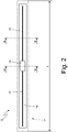
Figure 2 , thetransponder 13 comprises an electronic circuit 14 (that is, a microchip) equipped with a non-volatile memory (typically, EEPROM or FRAM, the latter more costly, but technologically more advanced), anantenna 15 connected to theelectronic circuit 14, and asupport 16, which carries both theelectronic circuit 14 and theantenna 15 and is frequently defined as a "substrate" (typically it is made of a thin layer of mylar, plastic like PET or PVC, or other similar materials). In the embodiment illustrated inFigure 2 , theantenna 15 is a dipole antenna (or simply a dipole) and is made of two equal open arms constructed with a linear electrical conductor on which the currents flow that remotely irradiate the electromagnetic field. - In use, the
antenna 15 receives an electromagnetic signal that, by electromagnetic induction, induces a difference in electrical potential in theantenna 15, which generates the circulation of an electrical current in theelectronic circuit 14 to supply power to theelectronic circuit 14 itself; theelectronic circuit 14, thus activated, transmits the data contained within the memory thereof by means of theantenna 15 and, where appropriate, also modifies the data contained within the memory thereof. - According to what illustrated in
Figures 2 and3 , thetransponder 13 is inserted in asleeve 17, which is made of twostrips 18 of green rubber superimposed and pressed one against the other (obviously, the rubber of the tworubber strips 18 is initially raw and is vulcanized together with the rest of thepneumatic tyre 1 during the final vulcanization of thepneumatic tyre 1 itself); in general, the twostrips 18 of green rubber of thesleeve 17 are 1-2 mm longer/wider than the transponder 13 (that is, than theelectronic circuit 14 and the antenna 15). The twostrips 18 of green rubber are initially parallelepiped and deform around the components of thetransponder 13 when they are pressed one against the other around thetransponder 13 itself. According to an alternative embodiment, the two strips ofrubber 18 of thesleeve 17 are vulcanized from the start (that is, the rubber of the twostrips 18 of rubber is vulcanized immediately). - According to a different embodiment (not illustrated), the
support 16 is absent and the function thereof is performed by thestrips 18 of rubber of thesleeve 17. - According to a preferred embodiment, the thickness T of the sleeve 17 (containing the
transponder 13 within the interior thereof) is overall between 0.6 and 2 mm, the width W of thesleeve 17 is approximately 8-12 mm, and the length L of thesleeve 17 is approximately 60-80 mm. - The
transponder 13 is arranged circumferentially, that is, it is arranged along a circumference centered on the axis of rotation of the pneumatic tyre; it is important to set forth that the transponder 13 (contained within the sleeve 17) has a parallelepiped rectangular form, and therefore in the interior of thepneumatic tyre 1 does not follow the circular progression of all of the other components of thepneumatic tyre 1. - As shown in
Figures 5 and6 , the transponder 13 (contained within the sleeve 17) is arranged at a radial distance (not zero) from an edge 19 (that is, a terminal end) of the body ply 3 (which is arranged below thetread plies 9 and, therefore, below thetread 7 in contact with theinnermost tread ply 9, and it is supported against an intermediate portion of thebody ply 3 itself); that is, an upper edge (end) of thetransponder 13 is arranged at a radial distance (not zero) from theedge 19 of thebody ply 3. Furthermore, the transponder 13 (contained within the sleeve 17) is arranged at a radial distance (not zero) from an edge 20 (that is, a terminal end) of the beads 4 (in particular an edge of thebead filler 6, at which thebead filler 6 terminates); that is, a lower edge (end) of thetransponder 13 is arranged at a radial distance (not zero) from theedge 20, radially more to the outside of thebead filler 6. - As shown in
Figures 5 and6 , the transponder 13 (contained within the sleeve 17) is entirely contained within aband 21 which is centered on the medial plane M of the height H of the cross section of thepneumatic tyre 1 and has an overall amplitude A between 16 and 24 mm (that is, the amplitude A can vary between 16 and 24 mm and is normally equal to 20 mm); in other words, the two ends of thebands 21 are arranged symmetrically at the same distance (overall between 8 and 12 mm, and normally equal to 10 mm) from the medial plane M of the height H of the cross section of thepneumatic tyre 1 in such a way that theband 21 is centered on the medial plane M of the height H of the cross section of thepneumatic tyre 1 and has the overall amplitude A between 16 and 24 mm. Thetransponder 13 being entirely contained within theband 21, each end of thetransponder 13 is arranged at a distance D1 or D2 less than 8-12 mm from the medial plane M of the height H of the cross section of thepneumatic tyre 1. - It is important to set forth that the
transponder 13 must be entirely contained within theband 21 which, as shown inFigures 5 and6 , is centered on the medial plane M of the height H of the cross section of thepneumatic tyre 1, but thetransponder 13 does not have to be centered on the medial plane M (that is, thetransponder 13 can easily be moved toward the maximum or minimum of theband 21 provided that the constraint of being entirely contained within theband 21 is complied therewith) . Consequently, as illustrated inFigures 5 and6 , thetransponder 13 is arranged in contact with thebody ply 3 at (in proximity to) the medial plane M of the height H of the cross section of thepneumatic tyre 1 and is not (necessarily) centered with respect to the medial plane M of the height H of the cross section of thepneumatic tyre 1. - As mentioned hereinbefore, the
transponder 13 is arranged radially more to the outside of thebead 4 and therefore radially more to the outside of thebead filler 6. Furthermore, thetransponder 13 is arranged more to the inside of thesidewall 11 and is radially arranged more to the outside of theabrasion gum strip 12; consequently, thetransponder 13 is arranged within a zone wherein thesidewall 11 is present and theabrasion gum strip 12 is not present. - In
Figure 5 , which is not according to the invention, the transponder 13 (contained within the sleeve 17) is arranged axially to the inside of the flap of thebody ply 3, and therefore is laterally (in other words, axially, that is, parallel to the axis of rotation of the pneumatic tyre 1) bordering thebody ply 3 on both sides; in other words, thetransponder 13 is in contact with both sides (in other words, on the right and on the left, that is, both internally and externally) with corresponding portions of thebody ply 3. - According to the invention, as seen in
Figure 6 , the transponder 13 (contained within the sleeve 17) is arranged axially to the exterior of the flap of thebody ply 3, and therefore is laterally (in other words, axially, that is, parallel to the axis of rotation of the pneumatic tyre 1) bordering on one side (internally) with thebody ply 3 and on the opposite side (externally) with thesidewall 11; in other words, thetransponder 13 is in contact internally with a corresponding portion of thebody ply 3 and is in contact externally with a corresponding portion of thesidewall 11. - As mentioned hereinbefore, the
transponder 13 is arranged circumferentially and has a parallelepiped rectangular form and in the interior of thepneumatic tyre 1 does not follow the circular progression of all the other components of thepneumatic tyre 1; as a result, as illustrated inFigure 7 , the radial distance D1 or D2 between each edge of thetransponder 13 and the medial plane M of the height H of the cross section of thepneumatic tyre 1 is continuously variable (even if 1-3 mm at the most) along the entire extent of thetransponder 13, inasmuch as thetransponder 13 has a rectangular progression, while the medial plane M of the height H of the cross section of thepneumatic tyre 1 has a circular progression. In this respect, it is important to set forth that the maximum (that is, the greatest possible) radial distance D1 or D2 between each edge of thetransponder 13 and the medial plane M of the height H of the cross section of thepneumatic tyre 1 is always less than 8-12 mm. - In the alternative embodiment illustrated in
Figures 8 and9 , theband 21 is no longer defined with respect to the medial plane M of the height H of the cross section of thepneumatic tyre 1, but it is defined with respect to theedge 19 of thebody ply 3 and with respect to theedge 20 radially more to the outside of thebead filler 6. In particular, a radially external end of theband 21 is arranged at a radial distance D3 equal to 10 mm from theedge 19 of thebody ply 3, while a radially internal end of theband 21 is arranged at a distance D3 equal to 10 mm from theedge 20 radially more to the outside of thebead filler 6. As a result, the transponder 13 (and in particular a radially external edge of the transponder 13) is located at a radial distance D4 greater than 10 mm from theedge 19 of thebody ply 3 and, at the same time, the transponder 13 (and in particular a radially internal edge of the transponder 13) is located at a radial distance D5 greater than 10 mm from theedge 20 radially more to the outside of thebead filler 6. - The band 21 (at the interior of which the
transponder 13 is completely contained) as shown inFigures 8 and9 is normally more expansive than theband 21 shown inFigures 5 and6 ; furthermore, the band 21 (at the interior of which thetransponder 13 is completely contained) shown inFigures 8 and9 is not normally centered with respect to the medial plane M of the height H of the cross section of thepneumatic tyre 1, unlike theband 21 shown inFigures 5 and6 . - As illustrated in
Figure 8 (analogously as illustrated inFigure 5 ), which is not according to the present invention, the transponder 13 (contained within the sleeve 17) is arranged axially to the inside of the flap of thebody ply 3, and therefore is laterally (in other words, axially, that is, parallel to the axis of rotation of the pneumatic tyre 1) bordering the body ply 3 on both sides; in other words, thetransponder 13 is in contact with both sides (in other words, on the right and on the left, that is, both internally and externally) with corresponding portions of thebody ply 3. - According to the invention, as illustrated in
Figure 9 (analogously to the configuration as illustrated inFigure 6 ), the transponder 13 (contained within the sleeve 17) is arranged axially to the exterior of the flap of thebody ply 3, and therefore is laterally (in other words, axially, that is, parallel to the axis of rotation of the pneumatic tyre 1) bordering on one side (internally) with thebody ply 3 and on the opposite side (externally) with thesidewall 11; in other words, thetransponder 13 is in contact internally with a corresponding portion of thebody ply 3 and is in contact externally with a corresponding portion of thesidewall 11. - It is important to set forth that the body ply 3 could be provided with local reinforcing elements, which are applied to limited portions of the
body ply 3; for example, the body ply 3 could be provided with a fabric reinforcement, which is applied in proximity to thebeads 4, and/or with a calendered "squeegee", which is also applied close to thebeads 4. In this case, such reinforcing elements become an integral part of thebody ply 3, and, therefore, thetransponder 13 can be arranged in contact with the body ply 3 also at such reinforcing elements. - The
pneumatic tyre 1 can be the "standard" type or else the "non-standard" type; for example, thepneumatic tyre 1 could be of the "run-flat" type, of the "sponge" type (that is, provided internally with a spongy body having an acoustic effect), or of the "sealant" type (that is, provided with a sealing agent which is capable of closing any holes). - The embodiments described herein can be combined with each other without departing from the scope of the appended claims.
- The
pneumatic tyre 1 described above has many advantages. - First and foremost, in the aforementioned
pneumatic tyre 1 the position of thetransponder 13 makes it possible to minimize the stresses and deformations to which thetransponder 13 is subjected (both during the construction of thepneumatic tyre 1 and during the use of the pneumatic tyre 1) and, at the same time, makes it possible to minimizetransponder 13 radio frequency communications disturbances and interference (in this way, thetransponder 13 can be read at a distance of over 3 meters if thepneumatic tyre 1 is not mounted on a metallic rim and at a distance of over 2 meters if thepneumatic tyre 1 is mounted on a metallic rim). - Furthermore, in the
pneumatic tyre 1 described above the presence of the transponder 13 (which is nevertheless a "foreign object" immersed within the pneumatic tyre 1) does not have a negative impact upon the performance and the durability (or upon the operating life) of thepneumatic tyre 1 itself. - As illustrated in
Figures 5 and8 , thetransponder 13 is better protected from the exterior insofar as it is located more to the inside of a layer of thebody ply 3. According to the invention as illustrated inFigures 6 and9 , local deformations of the body ply 3 are avoided, and the risk of entrapping air inside the body ply 3 at thetransponder 13 is completely avoided, because the space for housing thetransponder 13 is completely formed in locally deforming only the sidewall 11 (which is made of a thick layer of rubber and therefore has great deformation capacity). - Finally, the construction of the
pneumatic tyre 1 described above is simple, inasmuch as thetransponder 1 can easily be made to adhere to the body ply 3 when the body ply 3 is still completely flat (that is, before wrapping the body ply 3 around the forming drum) or thetransponder 1 can easily be made to adhere to asidewall 11 before mounting thesidewall 11 itself; obviously, thetransponder 1 can be made to adhere to asidewall 11 as illustrated inFigures 6 and9 , while thetransponder 1 can be made to adhere to the body ply 3 in all of the embodiments. -
- 1
- pneumatic tyre
- 2
- carcass
- 3
- body ply
- 4
- beads
- 5
- bead core
- 6
- bead filler
- 7
- tread
- 8
- tread belt
- 9
- tread plies
- 10
- innerliner
- 11
- sidewalls
- 12
- abrasion gum strips
- 13
- transponder
- 14
- electronic circuit
- 15
- antenna
- 16
- support
- 17
- sleeve
- 18
- strips
- 19
- edge
- 20
- edge
- 21
- band
- H
- height
- L
- length
- W
- width
- T
- thickness
- A
- amplitude
- D1
- distance
- D2
- distance
- D3
- distance
- D4
- distance
- D5
- distance
Claims (8)
- Pneumatic tyre (1) comprising:a toroidal carcass (2), which is made up of a unique and single body ply (3) partially collapsed onto itself and therefore having two lateral flaps, in each of which an edge of the body ply (3) rests against an intermediate portion of the body ply (3) itself;two annular beads (4), each of which is surrounded by the body ply (3) and has a bead core (5) and a bead filler (6) ;an annular tread (7);a tread belt (8) comprising at least one body ply (9); a pair of sidewalls (11) arranged axially outside to the body ply (3) between the tread (7) and the beads (4);a pair of abrasion gum strips (12) arranged axially outside to the body ply (3), radially more to the inside of the sidewalls (13), and at the beads (4); anda transponder (13) which is arranged in contact with the body ply (3) at a flap of the body ply (3) and is located radially between an edge (19) of the body ply (3) and a radially outer edge (20) of the bead filler (6);the pneumatic tyre (1) is characterized in that:each flap of the body ply (3) terminates radially below the tread ply (9) in such a way that in each flap of the body ply (3) the edge (19) of the body ply (3) is in contact with the tread ply (9);the transponder (13) is axially arranged on the outside of the flap of the body ply (3), is axially inside in contact with a corresponding portion of the body ply (3), and is axially outside in contact with a corresponding portion of the sidewall (11);a first radial distance (D4) greater than 10 mm is provided between a radially outer end of the transponder (13) and the edge (19) of the body ply (3); anda second radial distance (D5) greater than 10 mm is provided between a radially inner end of the transponder (13) and the radially outer edge (20) of the bead filler (6) .
- Pneumatic tyre (1) according to claim 1, wherein each end of the transponder (13) is arranged at a third radial distance (Dl, D2) of less than 10 mm from a medial plane (M) of a height (H) of a cross section of the pneumatic tyre (1).
- Pneumatic tyre (1) according to claim 1 or 2, wherein the transponder (13) is contained within a band (21) which is centered on the medial plane (M) of the height (H) of the cross section of the pneumatic tyre (1) and has an overall radial dimension (A) between 16-24 mm, preferably 20 mm.
- Pneumatic tyre (1) according to claim 1, 2 or 3, wherein the transponder (13) is arranged within a zone wherein the sidewall (11) is present and the abrasion gum strip (12) is not present.
- Pneumatic tyre (1) according to one of the claims from 1 to 4, wherein the transponder (13) is inserted within a sleeve (17) made of two strips (18) of rubber superimposed and pressed one onto the other.
- Pneumatic tyre (1) according to claim 5, wherein the two strips of rubber (18) of the sleeve (17) are 1-2 mm longer/wider than the transponder (13).
- Pneumatic tyre (1) according to claim 5 or 6, wherein the two strips of rubber (18) are deformed around the components of the transponder (13).
- Pneumatic tyre (1) according to one of the claims from 1 to 7, wherein the transponder (13) is circumferentially arranged, has a rectilinear form, and therefore in the interior of the pneumatic tyre (1) does not follow the circular progression of all of the other components of the pneumatic tyre (1).
Applications Claiming Priority (2)
| Application Number | Priority Date | Filing Date | Title |
|---|---|---|---|
| IT102018000004925A IT201800004925A1 (en) | 2018-04-27 | 2018-04-27 | TIRE FITTED WITH A TRANSPONDER |
| PCT/IB2019/053174 WO2019207422A1 (en) | 2018-04-27 | 2019-04-17 | Pneumatic tyre equipped with a transponder |
Publications (2)
| Publication Number | Publication Date |
|---|---|
| EP3784504A1 EP3784504A1 (en) | 2021-03-03 |
| EP3784504B1 true EP3784504B1 (en) | 2022-07-27 |
Family
ID=62952327
Family Applications (1)
| Application Number | Title | Priority Date | Filing Date |
|---|---|---|---|
| EP19724933.7A Active EP3784504B1 (en) | 2018-04-27 | 2019-04-17 | Pneumatic tyre equipped with a transponder |
Country Status (7)
| Country | Link |
|---|---|
| US (1) | US11541703B2 (en) |
| EP (1) | EP3784504B1 (en) |
| JP (1) | JP7024118B2 (en) |
| CN (1) | CN112262049A (en) |
| ES (1) | ES2926246T3 (en) |
| IT (1) | IT201800004925A1 (en) |
| WO (1) | WO2019207422A1 (en) |
Families Citing this family (8)
| Publication number | Priority date | Publication date | Assignee | Title |
|---|---|---|---|---|
| IT201800004917A1 (en) * | 2018-04-27 | 2019-10-27 | TIRE FITTED WITH A TRANSPONDER | |
| JP6594504B1 (en) | 2018-10-03 | 2019-10-23 | Toyo Tire株式会社 | tire |
| JP6667045B1 (en) * | 2019-11-27 | 2020-03-18 | 横浜ゴム株式会社 | Pneumatic tire |
| JP7484187B2 (en) * | 2020-01-29 | 2024-05-16 | 住友ゴム工業株式会社 | Safety Tires |
| JP7457250B2 (en) * | 2020-06-29 | 2024-03-28 | 横浜ゴム株式会社 | pneumatic tires |
| JP7525448B2 (en) * | 2021-06-30 | 2024-07-30 | 株式会社ブリヂストン | Tire, retread tire, and method for manufacturing retread tire |
| JP7573494B2 (en) * | 2021-06-30 | 2024-10-25 | 株式会社ブリヂストン | tire |
| IT202100027812A1 (en) * | 2021-10-29 | 2023-04-29 | Bridgestone Europe Nv Sa | METHOD OF PRODUCTION OF A TIRE EQUIPPED WITH AN ELECTRONIC DEVICE |
Family Cites Families (15)
| Publication number | Priority date | Publication date | Assignee | Title |
|---|---|---|---|---|
| JPH06122302A (en) * | 1992-10-12 | 1994-05-06 | Bridgestone Corp | Pneumatic radial tire |
| JP2001354013A (en) * | 2000-06-14 | 2001-12-25 | Sumitomo Rubber Ind Ltd | Pneumatic tire |
| FR2870397A1 (en) * | 2004-05-13 | 2005-11-18 | Michelin Soc Tech | RUBBER ARTICLE WIRING WITH INTEGRATED ELECTRONICS AND METHOD FOR INSTRUMENTING SUCH ARTICLE |
| FR2914585B1 (en) * | 2007-04-03 | 2009-07-03 | Michelin Soc Tech | PNEUMATIC COMPRISING AN ELECTRONIC MEMBER AND METHOD OF MANUFACTURING SUCH PNEUMATIC |
| EP1978345B1 (en) * | 2007-04-06 | 2014-05-07 | Sumitomo Rubber Industries, Ltd. | Method for estimating magnitude of force acting on rolling tire |
| FR2936185B1 (en) * | 2008-09-25 | 2011-09-23 | Michelin Soc Tech | PNEUMATIC HAVING A DELETED ANTENNA ORGAN |
| FR2937284B1 (en) * | 2008-10-20 | 2010-11-19 | Michelin Soc Tech | INSTRUMENT PNEUMATIC AND PNEUMATIC BODY |
| US20100122757A1 (en) * | 2008-11-18 | 2010-05-20 | Robert Edward Lionetti | Tire and electronic device assembly |
| KR101081374B1 (en) | 2009-01-09 | 2011-11-08 | 한국타이어 주식회사 | Method for applying a radiofrequency identification tag in tire |
| KR101312841B1 (en) * | 2011-12-15 | 2013-09-30 | 금호타이어 주식회사 | Tire with RFID antenna |
| JP2015223918A (en) * | 2014-05-27 | 2015-12-14 | 株式会社ブリヂストン | Pneumatic tire provided with electronic component and method for manufacturing same |
| FR3037200B1 (en) | 2015-06-03 | 2017-05-26 | Michelin & Cie | RADIOFREQUENCY TRANSPONDER FOR PNEUMATIC |
| FR3059607A1 (en) * | 2016-12-05 | 2018-06-08 | Compagnie Generale Des Etablissements Michelin | RADIO FREQUENCY COMMUNICATION MODULE FOR TIRES |
| EP3677450B1 (en) * | 2017-09-12 | 2022-10-12 | Sumitomo Rubber Industries, Ltd. | Pneumatic tire |
| JP6594504B1 (en) * | 2018-10-03 | 2019-10-23 | Toyo Tire株式会社 | tire |
-
2018
- 2018-04-27 IT IT102018000004925A patent/IT201800004925A1/en unknown
-
2019
- 2019-04-17 ES ES19724933T patent/ES2926246T3/en active Active
- 2019-04-17 EP EP19724933.7A patent/EP3784504B1/en active Active
- 2019-04-17 JP JP2020560181A patent/JP7024118B2/en active Active
- 2019-04-17 WO PCT/IB2019/053174 patent/WO2019207422A1/en not_active Ceased
- 2019-04-17 CN CN201980038976.9A patent/CN112262049A/en active Pending
- 2019-04-17 US US17/050,572 patent/US11541703B2/en active Active
Also Published As
| Publication number | Publication date |
|---|---|
| WO2019207422A1 (en) | 2019-10-31 |
| ES2926246T3 (en) | 2022-10-24 |
| US11541703B2 (en) | 2023-01-03 |
| JP2021518830A (en) | 2021-08-05 |
| US20210237522A1 (en) | 2021-08-05 |
| EP3784504A1 (en) | 2021-03-03 |
| IT201800004925A1 (en) | 2019-10-27 |
| CN112262049A (en) | 2021-01-22 |
| JP7024118B2 (en) | 2022-02-22 |
Similar Documents
| Publication | Publication Date | Title |
|---|---|---|
| EP3784504B1 (en) | Pneumatic tyre equipped with a transponder | |
| US12459308B2 (en) | Pneumatic tire equipped with a transponder | |
| EP3921186B1 (en) | Pneumatic tyre equipped with a transponder | |
| EP3921187B1 (en) | Pneumatic tyre equipped with a transponder | |
| EP4422854B1 (en) | Method of producing a tyre equipped with an electronic device | |
| RU2796079C2 (en) | Pneumatic tire equipped with a transponder | |
| RU2798384C2 (en) | Pneumatic tire equipped with a transponder | |
| EP4282670B1 (en) | Tire | |
| WO2025099654A1 (en) | Pneumatic tyre equipped with an electronic device | |
| IT201900001559A1 (en) | TIRE FITTED WITH A TRANSPONDER |
Legal Events
| Date | Code | Title | Description |
|---|---|---|---|
| STAA | Information on the status of an ep patent application or granted ep patent |
Free format text: STATUS: UNKNOWN |
|
| STAA | Information on the status of an ep patent application or granted ep patent |
Free format text: STATUS: THE INTERNATIONAL PUBLICATION HAS BEEN MADE |
|
| PUAI | Public reference made under article 153(3) epc to a published international application that has entered the european phase |
Free format text: ORIGINAL CODE: 0009012 |
|
| STAA | Information on the status of an ep patent application or granted ep patent |
Free format text: STATUS: REQUEST FOR EXAMINATION WAS MADE |
|
| 17P | Request for examination filed |
Effective date: 20201125 |
|
| AK | Designated contracting states |
Kind code of ref document: A1 Designated state(s): AL AT BE BG CH CY CZ DE DK EE ES FI FR GB GR HR HU IE IS IT LI LT LU LV MC MK MT NL NO PL PT RO RS SE SI SK SM TR |
|
| AX | Request for extension of the european patent |
Extension state: BA ME |
|
| DAV | Request for validation of the european patent (deleted) | ||
| DAX | Request for extension of the european patent (deleted) | ||
| STAA | Information on the status of an ep patent application or granted ep patent |
Free format text: STATUS: EXAMINATION IS IN PROGRESS |
|
| 17Q | First examination report despatched |
Effective date: 20211108 |
|
| GRAP | Despatch of communication of intention to grant a patent |
Free format text: ORIGINAL CODE: EPIDOSNIGR1 |
|
| STAA | Information on the status of an ep patent application or granted ep patent |
Free format text: STATUS: GRANT OF PATENT IS INTENDED |
|
| INTG | Intention to grant announced |
Effective date: 20220218 |
|
| GRAS | Grant fee paid |
Free format text: ORIGINAL CODE: EPIDOSNIGR3 |
|
| GRAA | (expected) grant |
Free format text: ORIGINAL CODE: 0009210 |
|
| STAA | Information on the status of an ep patent application or granted ep patent |
Free format text: STATUS: THE PATENT HAS BEEN GRANTED |
|
| AK | Designated contracting states |
Kind code of ref document: B1 Designated state(s): AL AT BE BG CH CY CZ DE DK EE ES FI FR GB GR HR HU IE IS IT LI LT LU LV MC MK MT NL NO PL PT RO RS SE SI SK SM TR |
|
| REG | Reference to a national code |
Ref country code: CH Ref legal event code: EP |
|
| REG | Reference to a national code |
Ref country code: DE Ref legal event code: R096 Ref document number: 602019017500 Country of ref document: DE |
|
| REG | Reference to a national code |
Ref country code: AT Ref legal event code: REF Ref document number: 1506842 Country of ref document: AT Kind code of ref document: T Effective date: 20220815 |
|
| REG | Reference to a national code |
Ref country code: IE Ref legal event code: FG4D |
|
| REG | Reference to a national code |
Ref country code: ES Ref legal event code: FG2A Ref document number: 2926246 Country of ref document: ES Kind code of ref document: T3 Effective date: 20221024 |
|
| REG | Reference to a national code |
Ref country code: LT Ref legal event code: MG9D |
|
| REG | Reference to a national code |
Ref country code: NL Ref legal event code: MP Effective date: 20220727 |
|
| PG25 | Lapsed in a contracting state [announced via postgrant information from national office to epo] |
Ref country code: SE Free format text: LAPSE BECAUSE OF FAILURE TO SUBMIT A TRANSLATION OF THE DESCRIPTION OR TO PAY THE FEE WITHIN THE PRESCRIBED TIME-LIMIT Effective date: 20220727 Ref country code: RS Free format text: LAPSE BECAUSE OF FAILURE TO SUBMIT A TRANSLATION OF THE DESCRIPTION OR TO PAY THE FEE WITHIN THE PRESCRIBED TIME-LIMIT Effective date: 20220727 Ref country code: PT Free format text: LAPSE BECAUSE OF FAILURE TO SUBMIT A TRANSLATION OF THE DESCRIPTION OR TO PAY THE FEE WITHIN THE PRESCRIBED TIME-LIMIT Effective date: 20221128 Ref country code: NO Free format text: LAPSE BECAUSE OF FAILURE TO SUBMIT A TRANSLATION OF THE DESCRIPTION OR TO PAY THE FEE WITHIN THE PRESCRIBED TIME-LIMIT Effective date: 20221027 Ref country code: NL Free format text: LAPSE BECAUSE OF FAILURE TO SUBMIT A TRANSLATION OF THE DESCRIPTION OR TO PAY THE FEE WITHIN THE PRESCRIBED TIME-LIMIT Effective date: 20220727 Ref country code: LV Free format text: LAPSE BECAUSE OF FAILURE TO SUBMIT A TRANSLATION OF THE DESCRIPTION OR TO PAY THE FEE WITHIN THE PRESCRIBED TIME-LIMIT Effective date: 20220727 Ref country code: LT Free format text: LAPSE BECAUSE OF FAILURE TO SUBMIT A TRANSLATION OF THE DESCRIPTION OR TO PAY THE FEE WITHIN THE PRESCRIBED TIME-LIMIT Effective date: 20220727 Ref country code: FI Free format text: LAPSE BECAUSE OF FAILURE TO SUBMIT A TRANSLATION OF THE DESCRIPTION OR TO PAY THE FEE WITHIN THE PRESCRIBED TIME-LIMIT Effective date: 20220727 |
|
| REG | Reference to a national code |
Ref country code: AT Ref legal event code: MK05 Ref document number: 1506842 Country of ref document: AT Kind code of ref document: T Effective date: 20220727 |
|
| PG25 | Lapsed in a contracting state [announced via postgrant information from national office to epo] |
Ref country code: PL Free format text: LAPSE BECAUSE OF FAILURE TO SUBMIT A TRANSLATION OF THE DESCRIPTION OR TO PAY THE FEE WITHIN THE PRESCRIBED TIME-LIMIT Effective date: 20220727 Ref country code: IS Free format text: LAPSE BECAUSE OF FAILURE TO SUBMIT A TRANSLATION OF THE DESCRIPTION OR TO PAY THE FEE WITHIN THE PRESCRIBED TIME-LIMIT Effective date: 20221127 Ref country code: HR Free format text: LAPSE BECAUSE OF FAILURE TO SUBMIT A TRANSLATION OF THE DESCRIPTION OR TO PAY THE FEE WITHIN THE PRESCRIBED TIME-LIMIT Effective date: 20220727 Ref country code: GR Free format text: LAPSE BECAUSE OF FAILURE TO SUBMIT A TRANSLATION OF THE DESCRIPTION OR TO PAY THE FEE WITHIN THE PRESCRIBED TIME-LIMIT Effective date: 20221028 |
|
| RAP4 | Party data changed (patent owner data changed or rights of a patent transferred) |
Owner name: BRIDGESTONE EUROPE NV/SA |
|
| PG25 | Lapsed in a contracting state [announced via postgrant information from national office to epo] |
Ref country code: SM Free format text: LAPSE BECAUSE OF FAILURE TO SUBMIT A TRANSLATION OF THE DESCRIPTION OR TO PAY THE FEE WITHIN THE PRESCRIBED TIME-LIMIT Effective date: 20220727 Ref country code: RO Free format text: LAPSE BECAUSE OF FAILURE TO SUBMIT A TRANSLATION OF THE DESCRIPTION OR TO PAY THE FEE WITHIN THE PRESCRIBED TIME-LIMIT Effective date: 20220727 Ref country code: DK Free format text: LAPSE BECAUSE OF FAILURE TO SUBMIT A TRANSLATION OF THE DESCRIPTION OR TO PAY THE FEE WITHIN THE PRESCRIBED TIME-LIMIT Effective date: 20220727 Ref country code: CZ Free format text: LAPSE BECAUSE OF FAILURE TO SUBMIT A TRANSLATION OF THE DESCRIPTION OR TO PAY THE FEE WITHIN THE PRESCRIBED TIME-LIMIT Effective date: 20220727 Ref country code: AT Free format text: LAPSE BECAUSE OF FAILURE TO SUBMIT A TRANSLATION OF THE DESCRIPTION OR TO PAY THE FEE WITHIN THE PRESCRIBED TIME-LIMIT Effective date: 20220727 |
|
| REG | Reference to a national code |
Ref country code: DE Ref legal event code: R097 Ref document number: 602019017500 Country of ref document: DE |
|
| PG25 | Lapsed in a contracting state [announced via postgrant information from national office to epo] |
Ref country code: SK Free format text: LAPSE BECAUSE OF FAILURE TO SUBMIT A TRANSLATION OF THE DESCRIPTION OR TO PAY THE FEE WITHIN THE PRESCRIBED TIME-LIMIT Effective date: 20220727 Ref country code: EE Free format text: LAPSE BECAUSE OF FAILURE TO SUBMIT A TRANSLATION OF THE DESCRIPTION OR TO PAY THE FEE WITHIN THE PRESCRIBED TIME-LIMIT Effective date: 20220727 |
|
| PLBE | No opposition filed within time limit |
Free format text: ORIGINAL CODE: 0009261 |
|
| STAA | Information on the status of an ep patent application or granted ep patent |
Free format text: STATUS: NO OPPOSITION FILED WITHIN TIME LIMIT |
|
| P01 | Opt-out of the competence of the unified patent court (upc) registered |
Effective date: 20230511 |
|
| PG25 | Lapsed in a contracting state [announced via postgrant information from national office to epo] |
Ref country code: AL Free format text: LAPSE BECAUSE OF FAILURE TO SUBMIT A TRANSLATION OF THE DESCRIPTION OR TO PAY THE FEE WITHIN THE PRESCRIBED TIME-LIMIT Effective date: 20220727 |
|
| 26N | No opposition filed |
Effective date: 20230502 |
|
| PG25 | Lapsed in a contracting state [announced via postgrant information from national office to epo] |
Ref country code: SI Free format text: LAPSE BECAUSE OF FAILURE TO SUBMIT A TRANSLATION OF THE DESCRIPTION OR TO PAY THE FEE WITHIN THE PRESCRIBED TIME-LIMIT Effective date: 20220727 |
|
| REG | Reference to a national code |
Ref country code: CH Ref legal event code: PL |
|
| GBPC | Gb: european patent ceased through non-payment of renewal fee |
Effective date: 20230417 |
|
| PG25 | Lapsed in a contracting state [announced via postgrant information from national office to epo] |
Ref country code: LU Free format text: LAPSE BECAUSE OF NON-PAYMENT OF DUE FEES Effective date: 20230417 |
|
| REG | Reference to a national code |
Ref country code: BE Ref legal event code: MM Effective date: 20230430 |
|
| PG25 | Lapsed in a contracting state [announced via postgrant information from national office to epo] |
Ref country code: MC Free format text: LAPSE BECAUSE OF FAILURE TO SUBMIT A TRANSLATION OF THE DESCRIPTION OR TO PAY THE FEE WITHIN THE PRESCRIBED TIME-LIMIT Effective date: 20220727 |
|
| PG25 | Lapsed in a contracting state [announced via postgrant information from national office to epo] |
Ref country code: GB Free format text: LAPSE BECAUSE OF NON-PAYMENT OF DUE FEES Effective date: 20230417 |
|
| PG25 | Lapsed in a contracting state [announced via postgrant information from national office to epo] |
Ref country code: MC Free format text: LAPSE BECAUSE OF FAILURE TO SUBMIT A TRANSLATION OF THE DESCRIPTION OR TO PAY THE FEE WITHIN THE PRESCRIBED TIME-LIMIT Effective date: 20220727 Ref country code: LI Free format text: LAPSE BECAUSE OF NON-PAYMENT OF DUE FEES Effective date: 20230430 Ref country code: GB Free format text: LAPSE BECAUSE OF NON-PAYMENT OF DUE FEES Effective date: 20230417 Ref country code: CH Free format text: LAPSE BECAUSE OF NON-PAYMENT OF DUE FEES Effective date: 20230430 |
|
| REG | Reference to a national code |
Ref country code: IE Ref legal event code: MM4A |
|
| PG25 | Lapsed in a contracting state [announced via postgrant information from national office to epo] |
Ref country code: BE Free format text: LAPSE BECAUSE OF NON-PAYMENT OF DUE FEES Effective date: 20230430 |
|
| PG25 | Lapsed in a contracting state [announced via postgrant information from national office to epo] |
Ref country code: IE Free format text: LAPSE BECAUSE OF NON-PAYMENT OF DUE FEES Effective date: 20230417 |
|
| PG25 | Lapsed in a contracting state [announced via postgrant information from national office to epo] |
Ref country code: IE Free format text: LAPSE BECAUSE OF NON-PAYMENT OF DUE FEES Effective date: 20230417 |
|
| PG25 | Lapsed in a contracting state [announced via postgrant information from national office to epo] |
Ref country code: IT Free format text: LAPSE BECAUSE OF FAILURE TO SUBMIT A TRANSLATION OF THE DESCRIPTION OR TO PAY THE FEE WITHIN THE PRESCRIBED TIME-LIMIT Effective date: 20220727 |
|
| PG25 | Lapsed in a contracting state [announced via postgrant information from national office to epo] |
Ref country code: BG Free format text: LAPSE BECAUSE OF FAILURE TO SUBMIT A TRANSLATION OF THE DESCRIPTION OR TO PAY THE FEE WITHIN THE PRESCRIBED TIME-LIMIT Effective date: 20220727 |
|
| PG25 | Lapsed in a contracting state [announced via postgrant information from national office to epo] |
Ref country code: BG Free format text: LAPSE BECAUSE OF FAILURE TO SUBMIT A TRANSLATION OF THE DESCRIPTION OR TO PAY THE FEE WITHIN THE PRESCRIBED TIME-LIMIT Effective date: 20220727 |
|
| PGFP | Annual fee paid to national office [announced via postgrant information from national office to epo] |
Ref country code: DE Payment date: 20250319 Year of fee payment: 7 |
|
| PGFP | Annual fee paid to national office [announced via postgrant information from national office to epo] |
Ref country code: ES Payment date: 20250502 Year of fee payment: 7 |
|
| PG25 | Lapsed in a contracting state [announced via postgrant information from national office to epo] |
Ref country code: CY Free format text: LAPSE BECAUSE OF FAILURE TO SUBMIT A TRANSLATION OF THE DESCRIPTION OR TO PAY THE FEE WITHIN THE PRESCRIBED TIME-LIMIT; INVALID AB INITIO Effective date: 20190417 |
|
| PG25 | Lapsed in a contracting state [announced via postgrant information from national office to epo] |
Ref country code: HU Free format text: LAPSE BECAUSE OF FAILURE TO SUBMIT A TRANSLATION OF THE DESCRIPTION OR TO PAY THE FEE WITHIN THE PRESCRIBED TIME-LIMIT; INVALID AB INITIO Effective date: 20190417 |
|
| PG25 | Lapsed in a contracting state [announced via postgrant information from national office to epo] |
Ref country code: TR Free format text: LAPSE BECAUSE OF FAILURE TO SUBMIT A TRANSLATION OF THE DESCRIPTION OR TO PAY THE FEE WITHIN THE PRESCRIBED TIME-LIMIT Effective date: 20220727 |
|
| PGFP | Annual fee paid to national office [announced via postgrant information from national office to epo] |
Ref country code: FR Payment date: 20260320 Year of fee payment: 8 |