EP3784009B1 - Spring mounted slidable lock for rack components - Google Patents
Spring mounted slidable lock for rack components Download PDFInfo
- Publication number
- EP3784009B1 EP3784009B1 EP20191707.7A EP20191707A EP3784009B1 EP 3784009 B1 EP3784009 B1 EP 3784009B1 EP 20191707 A EP20191707 A EP 20191707A EP 3784009 B1 EP3784009 B1 EP 3784009B1
- Authority
- EP
- European Patent Office
- Prior art keywords
- rail
- post
- tab
- electronics rack
- base
- Prior art date
- Legal status (The legal status is an assumption and is not a legal conclusion. Google has not performed a legal analysis and makes no representation as to the accuracy of the status listed.)
- Active
Links
Images



Classifications
-
- H—ELECTRICITY
- H05—ELECTRIC TECHNIQUES NOT OTHERWISE PROVIDED FOR
- H05K—PRINTED CIRCUITS; CASINGS OR CONSTRUCTIONAL DETAILS OF ELECTRIC APPARATUS; MANUFACTURE OF ASSEMBLAGES OF ELECTRICAL COMPONENTS
- H05K7/00—Constructional details common to different types of electric apparatus
- H05K7/18—Construction of rack or frame
- H05K7/183—Construction of rack or frame support rails therefor
-
- H—ELECTRICITY
- H05—ELECTRIC TECHNIQUES NOT OTHERWISE PROVIDED FOR
- H05K—PRINTED CIRCUITS; CASINGS OR CONSTRUCTIONAL DETAILS OF ELECTRIC APPARATUS; MANUFACTURE OF ASSEMBLAGES OF ELECTRICAL COMPONENTS
- H05K7/00—Constructional details common to different types of electric apparatus
- H05K7/14—Mounting supporting structure in casing or on frame or rack
- H05K7/1485—Servers; Data center rooms, e.g. 19-inch computer racks
- H05K7/1488—Cabinets therefor, e.g. chassis or racks or mechanical interfaces between blades and support structures
- H05K7/1489—Cabinets therefor, e.g. chassis or racks or mechanical interfaces between blades and support structures characterized by the mounting of blades therein, e.g. brackets, rails, trays
-
- A—HUMAN NECESSITIES
- A47—FURNITURE; DOMESTIC ARTICLES OR APPLIANCES; COFFEE MILLS; SPICE MILLS; SUCTION CLEANERS IN GENERAL
- A47B—TABLES; DESKS; OFFICE FURNITURE; CABINETS; DRAWERS; GENERAL DETAILS OF FURNITURE
- A47B88/00—Drawers for tables, cabinets or like furniture; Guides for drawers
- A47B88/40—Sliding drawers; Slides or guides therefor
- A47B88/423—Fastening devices for slides or guides
- A47B88/43—Fastening devices for slides or guides at cabinet side
-
- H—ELECTRICITY
- H05—ELECTRIC TECHNIQUES NOT OTHERWISE PROVIDED FOR
- H05K—PRINTED CIRCUITS; CASINGS OR CONSTRUCTIONAL DETAILS OF ELECTRIC APPARATUS; MANUFACTURE OF ASSEMBLAGES OF ELECTRICAL COMPONENTS
- H05K7/00—Constructional details common to different types of electric apparatus
- H05K7/14—Mounting supporting structure in casing or on frame or rack
Definitions
- the invention relates to a device for attaching components to an electronics rack and, in particular, to slidable locking system for removably securing rack rails and other components to a rack assembly.
- a rack assembly is commonly used for securely storing and supporting electronic components, such as computer, audio, and video equipment.
- a rack assembly is an open framework including vertical mounting rails connected by top and bottom frames.
- rack rails may extend across the rack assembly from one vertical mounting post to another.
- the rack rails are generally bolted or otherwise fastened to the mounting rails, which requires the use of tools.
- the rack rails may include a static hook shape at each end so that the rack rails are held in slots in the mounting rails by the force of gravity acting on the rack rails themselves as well as on components supported by the rack rails. But the use of mechanical fasteners such as bolts can be cumbersome and time consuming, and relying on gravity alone risks that a rack rail can be dislodged inadvertently.
- US 2004/016712 discloses a bracket assembly that is removably attached to rail on an equipment rack, such as a computer rack, with a slide locking mechanism.
- the bracket assembly including a flat flange located at one end of the bracket assembly.
- a slide lock with has a base with a top surface and a flat bottom surface. The bottom surface slides along the flat flange of the bracket assembly.
- a release lever provides a surface for a user's finger to slide the support base along the flat flange.
- the slide locking mechanism also includes a locking latch assembly and a spring that biases the slide lock toward the end of the bracket assembly.
- US 10356938 discloses a connection device for connecting a rail to a rack post.
- the device includes a slidable unit that is connected to the rail.
- the device includes bracket with pillars or pins that protrude outward and extend into holes in the rack post.
- the slidable unit can be locked to the bracket to prevent the pins from being pulled out of the holes, thus securing the bracket to the post.
- a slot in the rail permits a user's finger to unlock the slidable unit, thereby releasing the pins from the rack post.
- Lever Lock ® fastening system Middle Atlantic Products, Inc. developed a unique locking system called the Lever Lock ® fastening system that uses a spring mounted pivotable latch for removably securing a rack support, such as a bracket or crossbar, to an electronics rack or shelving unit.
- the Lever Lock ® fastening system is described in United States Patent No. 9,131,622 .
- the Lever Lock ® fastening system has proven extremely successful. However, a pivotable latch might not work in tight locations.
- An electronics rack rail for use on an electronics rack which includes at least one slide locking mechanism for removably securing the rail to the rack.
- the rail includes a flat flange portion located at one end of the rail, the flat flange portion including a slot formed through the flat flange portion proximate to the end.
- the slide locking mechanism attached to the flat flange portion over the slot so that a portion of the slide mechanism extends through the slot.
- the slide lock mechanism includes a slide lock with a support base that has a top surface and a flat bottom surface.
- the bottom surface is configured to slide along the flat flange portion of the rail.
- the base has a width that is wider than a width of the slot so that the base is supported by the flat flange portion.
- a release lever protrudes from the top surface of the support base and provides a structure or surface for a user's finger to slide the support base along the flat flange portion.
- a locking latch extends downward from the bottom surface of the base and through the slot in the rail.
- the locking latch includes a neck portion attached to the bottom surface of the base and a protruding tab attached to an opposite end of the neck portion.
- the tab includes a forward face with a portion that slopes away from the bottom of the base and toward a back of the slide lock.
- the tab includes a top surface extending forward from the neck and is generally horizontal or slopes away from the bottom surface of the base. The top surface of the tab is spaced apart from the bottom surface of the base a distance to accommodate the flat flange portion and a flange on the electronics rack.
- a body extends downward from the bottom surface of the base and is spaced rearward and apart from the locking latch. The body extends through the slot in the rail.
- a spring is mounted to or formed on the body and engages with the rail so as to bias the slide lock toward the end of the rail.
- the spring is a coil spring with a first leg that extends into and contacts a rear surface of the slot and a second leg on an opposite side of the coil contacts a surface of the body.
- the spring is a lever formed on a portion of the housing which contacts the back of the slot.
- the body includes a recess within which the spring is located.
- the component may be a cross-rail, cross-bar, bracket, cable management cage, tray table, or shelf.
- the slope of the top surface may be in a range of between about 0 degrees to about 40 degrees.
- the slope of the top surface is in a range of between about 10 to about 25 degrees.
- an electronics rack is provided with a base, a top and at least four vertical posts, each post being attached to the base at one end and the top at another end.
- An electronics rack rail according to any of the embodiments disclosed herein is removably attached to at least one of the at least four vertical posts.
- a method for attaching an electronics rack rail according to any of the embodiments disclosed herein to a post of an electronics rack involves the steps of
- Another method is disclosed for attaching an electronics rack rail according to any of the embodiments disclosed herein to a post of an electronics rack. The method involves the steps of:
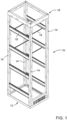
- Fig. 1 illustrates a generally conventional rack assembly 10.
- the rack assembly includes a bottom or base frame 12, which is generally square or rectangular in shape, and onto which a plurality of vertical posts or rails 14 are attached. The upper ends of the vertical posts attach to a top frame 16, also generally square or rectangular in shape.
- the rack assembly 10 includes one or more components 18 that are removably mounted to the vertical rails for configuring the rack assembly for a particular use.
- the components may include cross-rails, cross-bars, brackets, cable management cages, tray tables, and shelves.
- the components attach to and extend between adjacent vertical posts 14 of the rack assembly 10.
- a rail will be discussed below. However, a person skilled in the art would readily appreciate the applicability of the following description to cross-rails, cross-bars, brackets, cable management cages, tray tables, and shelves.
- a rack rail 18 attached to two vertical posts 14 is shown.
- the ends of the rail 18 include a slidable locking assembly 20 according to the present invention.
- the slidable locking assembly 20 removably engages with the vertical post 14.
- the rail 18 includes ends 18A and 18B, at least one of which includes the locking assembly 20.
- At least one end of the rail 18 preferably includes a planar or flat flange portion 18C proximate to the end 18A that lies along a plane 18P that is parallel to a longitudinal axis 18L of the rail 18 (i.e., the plane along which the locking assembly 20 slides).
- At least one projection or tab 22 (shown in Fig. 5A ) preferably extends from the flat flange portion 18C of the rail in a direction away from the longitudinal plane 18P.
- the protrusion 22 is preferably sized to fit into a recess or hole 14H in the vertical post 14 so as to assist in locking the rail to the post as will be explained in more detail below.
- each end 18A, 18B of the rail preferably has two projections 22, one located on either side of the locking assembly 20.
- the projection 22 can be formed by punching a portion of the rail end 18A out of its normal plane to form the projection 22 (see 5A.)
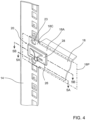
- the rail ends 18A, 18B can include holes 23 ( Fig. 4 ) that are located so as to align with the holes 14H in the vertical post 14.
- the holes 23 in the rail permit fasteners, such as screws or bolts to be inserted to provide additional securement of the rail to the post.
- the slidable locking assembly 20 is shown in more detail in Figs. 5A and 5B , which are cross-sectional views of the rail 18.
- the rail 18 preferably includes a slot or hole 24 formed through the flat flange portion 18C of the rail.
- the slot 24 is located proximate to an end 18A, 18B of the rail, but preferably does not extend all the way to the end.
- the locking assembly 20 includes a slide lock 26 that has a support base 28 with a top surface 28A and a flat bottom surface 28B.
- the flat bottom surface 28B is configured to slide along the flat flange portion 18C of the rail.
- the base 28 preferably has a width (in the lateral direction, perpendicular to the sliding direction) that is wider than the width of the slot 24.
- the slide lock 26 is supported by the flat flange portion 18C of the rail as it slides along the top surface of the flat flange portion 18C.
- the slide lock 26 includes a release lever 30 that protrudes or extends from the top surface 28A of the support base 28 and provides a structure or surface that a user can press on with their finger to slide the support base 28 along the surface of the flat flange portion 18C.
- a locking latch 32 Extending downward from the bottom surface 28B of the base 28 and through the slot 24 in the rail 18 is a locking latch 32.
- the locking latch 32 includes a neck portion 32A and a protruding tab 32B.
- the tab 32B includes a forward face 32C with a portion that slopes downward (away from the bottom of the base 28) and rearward (toward the back of the slide lock 26).
- the tab 32B also includes a top surface 32D extending forward from the neck 32A and is generally horizontal or slightly slopes away from the bottom surface 28B of the base 28.
- the top surface 32D of the tab 32B is spaced apart from the bottom surface 28B of the base 28 a sufficient distance to allow for the thickness of the flat flange portion 18C and the thickness of the flange of vertical post 14 as shown.
- the incorporation of a slope on the top surface 32D allows the slide lock 26 to accommodate flanges having different thicknesses in the rails (or other components) and posts.
- common rail thicknesses include 11 gauge and 14 gauge.
- the use of a sloped top surface of the slide lock in the present embodiment can accommodate both size rails, as well as other gauges and thicknesses.
- the slope of the top surface 32D, with respect to the horizontal, is preferably in a range of between about 0 degrees to about 40 degrees, more preferably, between about 10 to about 25 degrees. In one preferred embodiment the slope is between about 15 degrees to about 20 degrees, or more preferably, about 17.7 degrees. As will be more apparent below, the sloped face 32C forces the slide lock 26 to slide rearward when the locking latch 32 is inserted into a hole 14H in the vertical post 14.
- the slide lock 26 also includes a body 34 that extends downward from the bottom surface 28B of the base 28 and is spaced rearward and apart from the locking latch 32.
- the body 34 also extends through the slot 24.
- the body 34 includes a recess 34A within which a spring 36 is located.
- the spring 36 biases the slide lock 26 forward (toward the end of the rail.)
- the spring 36 is a coil spring with a first leg 36A that extends into and contacts the rear of the slot 24. A second leg (not shown) on the opposite side of the coil 36 would contact a surface of the body 34.
- springs or mechanisms can be used for urging the slide lock forward toward the vertical post.
- a portion of the body could be made from spring steel and be bent into spring lever (such as a leaf spring) which contacts the back of the slot directly.
- the spring 36 maintains the slide lock 26 at the forward end of the slot 24 in the rail 18. This corresponds to the initial or locked position.
- the user slides the slide lock rearward by applying pressure to the release lever 30 (the unlocked position).
- the user aligns the tab 32B with holes 14H in the vertical post (and if the rail includes projections 22, the projections 22 are also aligned with adjacent holes 14H).
- the user moves the bottom surface of the rail 18 toward the top surface of the vertical post, inserting the tab 32B through the hole 14H (and allowing the protections 22 to enter the adjacent holes 14H if applicable).
- the user releases the release lever 30 and the spring 36 urges the slide lock 26 toward the vertical post 14 causing the tab 32B to capture and lock the rail to the flange of the vertical post.
- the user need not slide the slide lock 26 rearward. Instead, the user aligns the projections 22 and the tab 32B with holes 14H in the vertical post. The user moves the bottom surface of the rail 18 toward the top surface of the vertical post. As the tab 32B slides into the hole 14H, the sloped portion of the forward face 32C contacts the edge of the hole 14H and forces the slide lock 26 to slide rearward in the slot 24 until the top 32D passes through the hole 14H. At that point, the rail will be lying on the top surface of the vertical post 14 (with the optional projections 22 in the adjacent holes), the force of the spring 36 urges the slide lock 26 toward the vertical post 14 causing the tab 32B to capture and lock the rail to the flange of the vertical post.
- the user simply slides the release lever 30 rearward causing the slide lock 26 to slide along the plane 18P into the unlocked position. This causes the tab 32B to slide rearward and out of engagement with the flange of the vertical post. The user then separates the rail from the vertical post.
Landscapes
- Engineering & Computer Science (AREA)
- Microelectronics & Electronic Packaging (AREA)
- Computer Hardware Design (AREA)
- General Engineering & Computer Science (AREA)
- Drawers Of Furniture (AREA)
Description
- The invention relates to a device for attaching components to an electronics rack and, in particular, to slidable locking system for removably securing rack rails and other components to a rack assembly.
- An electronics rack or rack assembly is commonly used for securely storing and supporting electronic components, such as computer, audio, and video equipment. Typically, a rack assembly is an open framework including vertical mounting rails connected by top and bottom frames. To enable the rack assembly to accommodate various size components at desired locations, rack rails may extend across the rack assembly from one vertical mounting post to another. In conventional commercially available systems, the rack rails are generally bolted or otherwise fastened to the mounting rails, which requires the use of tools. Alternatively, the rack rails may include a static hook shape at each end so that the rack rails are held in slots in the mounting rails by the force of gravity acting on the rack rails themselves as well as on components supported by the rack rails. But the use of mechanical fasteners such as bolts can be cumbersome and time consuming, and relying on gravity alone risks that a rack rail can be dislodged inadvertently.
-
US 2004/016712 discloses a bracket assembly that is removably attached to rail on an equipment rack, such as a computer rack, with a slide locking mechanism. The bracket assembly including a flat flange located at one end of the bracket assembly. A slide lock with has a base with a top surface and a flat bottom surface. The bottom surface slides along the flat flange of the bracket assembly. A release lever provides a surface for a user's finger to slide the support base along the flat flange. The slide locking mechanism also includes a locking latch assembly and a spring that biases the slide lock toward the end of the bracket assembly. -
US 10356938 - Middle Atlantic Products, Inc. developed a unique locking system called the Lever Lock® fastening system that uses a spring mounted pivotable latch for removably securing a rack support, such as a bracket or crossbar, to an electronics rack or shelving unit. The Lever Lock® fastening system is described in
United States Patent No. 9,131,622 - Therefore, it would be desirable to have an improved rack rail locking mechanism to easily and removably secure a rack rail or other component to a rack assembly mounting rail.
- An electronics rack rail for use on an electronics rack is disclosed which includes at least one slide locking mechanism for removably securing the rail to the rack. The rail includes a flat flange portion located at one end of the rail, the flat flange portion including a slot formed through the flat flange portion proximate to the end. The slide locking mechanism attached to the flat flange portion over the slot so that a portion of the slide mechanism extends through the slot.
- The slide lock mechanism includes a slide lock with a support base that has a top surface and a flat bottom surface. The bottom surface is configured to slide along the flat flange portion of the rail. The base has a width that is wider than a width of the slot so that the base is supported by the flat flange portion.
- A release lever protrudes from the top surface of the support base and provides a structure or surface for a user's finger to slide the support base along the flat flange portion.
- A locking latch extends downward from the bottom surface of the base and through the slot in the rail. The locking latch includes a neck portion attached to the bottom surface of the base and a protruding tab attached to an opposite end of the neck portion. The tab includes a forward face with a portion that slopes away from the bottom of the base and toward a back of the slide lock. The tab includes a top surface extending forward from the neck and is generally horizontal or slopes away from the bottom surface of the base. The top surface of the tab is spaced apart from the bottom surface of the base a distance to accommodate the flat flange portion and a flange on the electronics rack.
- A body extends downward from the bottom surface of the base and is spaced rearward and apart from the locking latch. The body extends through the slot in the rail.
- A spring is mounted to or formed on the body and engages with the rail so as to bias the slide lock toward the end of the rail.
- In an embodiment, the spring is a coil spring with a first leg that extends into and contacts a rear surface of the slot and a second leg on an opposite side of the coil contacts a surface of the body.
- In another embodiment, the spring is a lever formed on a portion of the housing which contacts the back of the slot.
- Optionally the body includes a recess within which the spring is located.
- The component may be a cross-rail, cross-bar, bracket, cable management cage, tray table, or shelf.
- The slope of the top surface may be in a range of between about 0 degrees to about 40 degrees. Optionally, the slope of the top surface is in a range of between about 10 to about 25 degrees.
- In an embodiment, an electronics rack is provided with a base, a top and at least four vertical posts, each post being attached to the base at one end and the top at another end. An electronics rack rail according to any of the embodiments disclosed herein is removably attached to at least one of the at least four vertical posts.
- A method is disclosed for attaching an electronics rack rail according to any of the embodiments disclosed herein to a post of an electronics rack. The method involves the steps of
- a. sliding the slide lock rearward by applying pressure to the release lever;
- b. aligning the tab with a hole in the post of the electronics rack;
- c. moving the bottom surface of the rail toward a top surface of the post;
- d. inserting the tab through the hole in the post; and
- e. releasing the release lever so that the spring urges the slide lock toward the post causing the tab to capture and lock the rail to the post.
- Another method is disclosed for attaching an electronics rack rail according to any of the embodiments disclosed herein to a post of an electronics rack. The method involves the steps of:
- a. aligning the tab with a hole in the post of the electronics rack;
- b. moving the bottom surface of the rail toward a top surface of the post;
- c. inserting the tab through the hole in the post so as to cause the sloped portion of a forward face of the tab to contact an edge of the hole to thereby force the slide lock to slide rearward in the slot until the top surface of the tab passes through the hole; and
- d. urging the slide lock toward the post with the spring to cause the tab to capture and lock the rail to the post.
- The foregoing and other features of the invention and advantages of the present invention will become more apparent in light of the following detailed description of the preferred embodiments, as illustrated in the accompanying figures. As will be realized, the invention is capable of modifications in various respects, all without departing from the invention. Accordingly, the drawings and the description are to be regarded as illustrative in nature, and not as restrictive.
- For the purpose of illustrating the invention, there are shown in the drawings embodiments that are presently preferred; it being understood, however, that this invention is not limited to the precise arrangements and constructions particularly shown.
-
Fig. 1 is a perspective view of an electronics rack with a removable locking assembly according to the present invention for attaching components to the rails and posts. -
Fig. 2 is an enlarged view illustrating one embodiment of a slide locking assembly according to the present invention used for securing a horizontal rail to two vertical posts. -
Fig. 3 is a section view of the horizontal rail and vertical posts ofFig. 2 taken along lines 3-3 inFig. 2 . -
Fig. 4 is an enlarged view of one slide locking assembly according to the present invention mounted on an end of the horizontal rail inFig. 2 . -
Fig. 5A is a cross-sectional view of the slide locking assembly, rail and post ofFig. 4 taken alonglines 5A-5A inFig. 4 . -
Fig. 5B is another cross-sectional view of the slide locking assembly, rail and post ofFig. 4 taken alonglines 5B-5B inFig. 4 . - Referring to the drawings, a preferred form of a spring mounted locking mechanism for a rack component is illustrated.
Fig. 1 illustrates a generallyconventional rack assembly 10. The rack assembly includes a bottom orbase frame 12, which is generally square or rectangular in shape, and onto which a plurality of vertical posts or rails 14 are attached. The upper ends of the vertical posts attach to atop frame 16, also generally square or rectangular in shape. Therack assembly 10 includes one ormore components 18 that are removably mounted to the vertical rails for configuring the rack assembly for a particular use. The components may include cross-rails, cross-bars, brackets, cable management cages, tray tables, and shelves. The components attach to and extend between adjacentvertical posts 14 of therack assembly 10. For simplicity, a rail will be discussed below. However, a person skilled in the art would readily appreciate the applicability of the following description to cross-rails, cross-bars, brackets, cable management cages, tray tables, and shelves. - Referring to
Fig. 2 , an enlarged view of arack rail 18 attached to twovertical posts 14 is shown. The ends of therail 18 include aslidable locking assembly 20 according to the present invention. As will be explained below, theslidable locking assembly 20 removably engages with thevertical post 14. In the illustrated embodiment, therail 18 includesends assembly 20. At least one end of therail 18 preferably includes a planar orflat flange portion 18C proximate to theend 18A that lies along aplane 18P that is parallel to alongitudinal axis 18L of the rail 18 (i.e., the plane along which the lockingassembly 20 slides). - In one optional configuration, at least one projection or tab 22 (shown in
Fig. 5A ) preferably extends from theflat flange portion 18C of the rail in a direction away from thelongitudinal plane 18P. Theprotrusion 22 is preferably sized to fit into a recess orhole 14H in thevertical post 14 so as to assist in locking the rail to the post as will be explained in more detail below. In the illustrated embodiment, eachend projections 22, one located on either side of the lockingassembly 20. Theprojection 22 can be formed by punching a portion of therail end 18A out of its normal plane to form the projection 22 (see 5A.) Alternatively, instead of protrusions, the rail ends 18A, 18B can include holes 23 (Fig. 4 ) that are located so as to align with theholes 14H in thevertical post 14. Theholes 23 in the rail permit fasteners, such as screws or bolts to be inserted to provide additional securement of the rail to the post. - The
slidable locking assembly 20 is shown in more detail inFigs. 5A and 5B , which are cross-sectional views of therail 18. Therail 18 preferably includes a slot orhole 24 formed through theflat flange portion 18C of the rail. Theslot 24 is located proximate to anend assembly 20 includes aslide lock 26 that has asupport base 28 with atop surface 28A and aflat bottom surface 28B. Theflat bottom surface 28B is configured to slide along theflat flange portion 18C of the rail. The base 28 preferably has a width (in the lateral direction, perpendicular to the sliding direction) that is wider than the width of theslot 24. As such, theslide lock 26 is supported by theflat flange portion 18C of the rail as it slides along the top surface of theflat flange portion 18C. - The
slide lock 26 includes arelease lever 30 that protrudes or extends from thetop surface 28A of thesupport base 28 and provides a structure or surface that a user can press on with their finger to slide thesupport base 28 along the surface of theflat flange portion 18C. Extending downward from thebottom surface 28B of thebase 28 and through theslot 24 in therail 18 is a lockinglatch 32. The lockinglatch 32 includes aneck portion 32A and a protrudingtab 32B. Thetab 32B includes aforward face 32C with a portion that slopes downward (away from the bottom of the base 28) and rearward (toward the back of the slide lock 26). Thetab 32B also includes atop surface 32D extending forward from theneck 32A and is generally horizontal or slightly slopes away from thebottom surface 28B of thebase 28. Thetop surface 32D of thetab 32B is spaced apart from thebottom surface 28B of the base 28 a sufficient distance to allow for the thickness of theflat flange portion 18C and the thickness of the flange ofvertical post 14 as shown. The incorporation of a slope on thetop surface 32D allows theslide lock 26 to accommodate flanges having different thicknesses in the rails (or other components) and posts. For example, common rail thicknesses include 11 gauge and 14 gauge. The use of a sloped top surface of the slide lock in the present embodiment can accommodate both size rails, as well as other gauges and thicknesses. The slope of thetop surface 32D, with respect to the horizontal, is preferably in a range of between about 0 degrees to about 40 degrees, more preferably, between about 10 to about 25 degrees. In one preferred embodiment the slope is between about 15 degrees to about 20 degrees, or more preferably, about 17.7 degrees. As will be more apparent below, the slopedface 32C forces theslide lock 26 to slide rearward when the lockinglatch 32 is inserted into ahole 14H in thevertical post 14. - The
slide lock 26 also includes abody 34 that extends downward from thebottom surface 28B of thebase 28 and is spaced rearward and apart from the lockinglatch 32. Thebody 34 also extends through theslot 24. Thebody 34 includes arecess 34A within which aspring 36 is located. Thespring 36 biases theslide lock 26 forward (toward the end of the rail.) In the illustrated embodiment, thespring 36 is a coil spring with afirst leg 36A that extends into and contacts the rear of theslot 24. A second leg (not shown) on the opposite side of thecoil 36 would contact a surface of thebody 34. Thus, when theslide lock 26 is urged rearward (away from the vertical post 14), thecoil spring 36 compresses (creating potential energy). When theslide lock 26 is released, the potential energy forces theslide lock 26 forward (toward the vertical post 14). - It should be readily apparent that other types of springs or mechanisms can be used for urging the slide lock forward toward the vertical post. For example, a portion of the body could be made from spring steel and be bent into spring lever (such as a leaf spring) which contacts the back of the slot directly.
- As should be apparent from the above discussion, the
spring 36 maintains theslide lock 26 at the forward end of theslot 24 in therail 18. This corresponds to the initial or locked position. There are two different methods for attaching therail 18 to thevertical post 14. In a first embodiment, the user slides the slide lock rearward by applying pressure to the release lever 30 (the unlocked position). The user then aligns thetab 32B withholes 14H in the vertical post (and if the rail includesprojections 22, theprojections 22 are also aligned withadjacent holes 14H). The user moves the bottom surface of therail 18 toward the top surface of the vertical post, inserting thetab 32B through thehole 14H (and allowing theprotections 22 to enter theadjacent holes 14H if applicable). Once the rail is lying on the top surface of thevertical post 14, the user releases therelease lever 30 and thespring 36 urges theslide lock 26 toward thevertical post 14 causing thetab 32B to capture and lock the rail to the flange of the vertical post. - Alternatively, the user need not slide the
slide lock 26 rearward. Instead, the user aligns theprojections 22 and thetab 32B withholes 14H in the vertical post. The user moves the bottom surface of therail 18 toward the top surface of the vertical post. As thetab 32B slides into thehole 14H, the sloped portion of theforward face 32C contacts the edge of thehole 14H and forces theslide lock 26 to slide rearward in theslot 24 until the top 32D passes through thehole 14H. At that point, the rail will be lying on the top surface of the vertical post 14 (with theoptional projections 22 in the adjacent holes), the force of thespring 36 urges theslide lock 26 toward thevertical post 14 causing thetab 32B to capture and lock the rail to the flange of the vertical post. - To remove the
rail 18 from the vertical post, the user simply slides therelease lever 30 rearward causing theslide lock 26 to slide along theplane 18P into the unlocked position. This causes thetab 32B to slide rearward and out of engagement with the flange of the vertical post. The user then separates the rail from the vertical post. - The use of the terms "a" and "an" and "the" and similar referents in the context of describing the invention (especially in the context of the following claims) are to be construed to cover both the singular and the plural, unless otherwise indicated herein or clearly contradicted by context. The terms "comprising," "having," "including," and "containing" are to be construed as open-ended terms (i.e., meaning "including, but not limited to,") unless otherwise noted. The term "connected" is to be construed as partly or wholly contained within, attached to, or joined together, even if there is something intervening.
- The recitation of ranges of values herein are merely intended to serve as a shorthand method of referring individually to each separate value falling within the range, unless otherwise indicated herein, and each separate value is incorporated into the specification as if it were individually recited herein.
- All methods described herein can be performed in any suitable order unless otherwise indicated herein or otherwise clearly contradicted by context. The use of any and all examples, or exemplary language (e.g., "such as") provided herein, is intended merely to better illuminate embodiments of the invention and does not impose a limitation on the scope of the invention unless otherwise claimed. The various embodiments and elements can be interchanged or combined in any suitable manner as necessary.
- The use of directions, such as forward, rearward, top and bottom, upper and lower are with reference to the embodiments shown in the drawings and, thus, should not be taken as restrictive. Reversing or flipping the embodiments in the drawings would, of course, result in consistent reversal or flipping of the terminology.
- No language in the specification should be construed as indicating any non-claimed element as essential to the practice of the invention.
- It will be apparent to those skilled in the art that various modifications and variations can be made to the present invention without departing from the scope of the invention. The intention is to cover all modifications, alternative constructions, and equivalents falling within the scope of the invention, as defined in the appended claims.
Claims (10)
- An electronics rack rail (18) removably attachable to an electronics rack (10), the rack rail (18) including at least one slide locking mechanism (20) for removably securing the rail (18) to the rack (10), the rail including a flat flange portion (18C) located at one end of the rail, the flat flange portion (18C) including a slot (24) formed through the flat flange portion (18C) proximate to the end, the slide locking mechanism (20) attached to the flat flange portion (18C) over the slot (24) so that a portion of the slide mechanism extends through the slot, the slide lock mechanism (20) comprising:a slide lock (26) with a support base (28) that has a top surface (28A) and a flat bottom surface (28B), the bottom surface configured to slide along the flat flange portion (18C) of the rail (18), the base has a width that is wider than a width of the slot (24) so that the base is supported by the flat flange portion (18C);a release lever (30) protrudes from the top surface (28A) of the support base (28) and provides a structure or surface for a user's finger to slide the support base (28) along the flat flange portion (18C);a locking latch (32) extends downward from the bottom surface (28B) of the base (28) and through the slot (24) in the rail, the locking latch (32) includes a neck portion (32A) attached to the bottom surface (28B) of the base and a protruding tab (32B) attached to an opposite end of the neck portion (32A), the tab (32B) includes a forward face (32C) with a portion that slopes away from the bottom of the base and toward a back of the slide lock (26), the tab (32B) includes a top surface (32D) extending forward from the neck (32A) and is generally horizontal or slopes away from the bottom surface (28B) of the base, the top surface (32D) of the tab is spaced apart from the bottom surface (28B) of the base a distance to accommodate the flat flange portion (18C) and a flange on the electronics rack;a body (34) extends downward from the bottom surface (28B) of the base and is spaced rearward and apart from the locking latch (32), the body (34) extends through the slot (24) in the rail; anda spring (36) mounted to or formed on the body (34) and engages with the rail (18) so as to bias the slide lock (26) toward the end of the rail (18).
- The electronics rack rail of claim 1, wherein the spring (36) is a coil spring with a first leg (36A) that extends into and contacts a rear surface of the slot (24) and a second leg on an opposite side of the coil contacts a surface of the body (34).
- The electronics rack rail of claim 1, wherein the spring (36) is a lever formed on a portion of the housing which contacts the back of the slot.
- The electronics rack rail of either claim 2 or 3, wherein the body includes a recess (34A) within which the spring (36) is located.
- The electronics rack rail of any of the preceding claims, wherein the rail (18) is selected from a group consisting of a cross-rail, cross-bar, bracket, cable management cage, tray table, and shelf.
- The electronics rack rail of any of the preceding claims, wherein the slope of the top surface (32D) is in a range of between about 0 degrees to about 40 degrees.
- The electronics rack rail of any of claims 1-5, wherein the slope of the top surface (32D) is in a range of between about 10 to about 25 degrees.
- An electronics rack (10) having a base (12), a top (16) and at least four vertical posts (14), each post (14) being attached to the base (12) at one end and the top (16) at another end; and an electronics rack rail (18) according to any of the preceding claims removably attached to at least one of the at least four vertical posts (14).
- A method of attaching an electronics rack rail (18) according to any of claims 1-7 to a post (14) of an electronics rack (10) comprising the steps ofsliding the slide lock (26) rearward by applying pressure to the release lever (30);aligning the tab (32B) with a hole in the post (14) of the electronics rack (10);moving the bottom surface of the rail (18) toward a top surface of the post (14);inserting the tab (32B) through the hole in the post (14); andreleasing the release lever (30) so that the spring (36) urges the slide lock (26) toward the post (14) causing the tab (32B) to capture and lock the rail (18) to the post (14).
- A method of attaching an electronics rack rail (18) according to any of claims 1-7 to a post (14) of an electronics rack (10) comprising the steps ofaligning the tab (32B) with a hole in the post (14) of the electronics rack (10);moving the bottom surface of the rail (18) toward a top surface of the post (14);inserting the tab (32B) through the hole in the post (14) so as to cause the sloped portion of a forward face (32C) of the tab (32B) to contact an edge of the hole to thereby force the slide lock (26) to slide rearward in the slot (24) until the top surface (32D) of the tab (32B) passes through the hole; andurging the slide lock (26) toward the post (14) with the spring (36) to cause the tab (32B) to capture and lock the rail (18) to the post (14).
Applications Claiming Priority (1)
| Application Number | Priority Date | Filing Date | Title |
|---|---|---|---|
| US16/545,732 US10524381B1 (en) | 2019-08-20 | 2019-08-20 | Spring mounted slidable lock for rack components |
Publications (2)
| Publication Number | Publication Date |
|---|---|
| EP3784009A1 EP3784009A1 (en) | 2021-02-24 |
| EP3784009B1 true EP3784009B1 (en) | 2024-05-29 |
Family
ID=69057403
Family Applications (1)
| Application Number | Title | Priority Date | Filing Date |
|---|---|---|---|
| EP20191707.7A Active EP3784009B1 (en) | 2019-08-20 | 2020-08-19 | Spring mounted slidable lock for rack components |
Country Status (2)
| Country | Link |
|---|---|
| US (1) | US10524381B1 (en) |
| EP (1) | EP3784009B1 (en) |
Families Citing this family (2)
| Publication number | Priority date | Publication date | Assignee | Title |
|---|---|---|---|---|
| US11337332B1 (en) * | 2020-10-30 | 2022-05-17 | ZT Group Intl, Inc. | Latch with auto-close |
| CN115226358B (en) * | 2021-04-19 | 2024-08-06 | 富联精密电子(天津)有限公司 | Support frame and data storage equipment cabinet |
Family Cites Families (14)
| Publication number | Priority date | Publication date | Assignee | Title |
|---|---|---|---|---|
| US6373707B1 (en) * | 2000-06-02 | 2002-04-16 | Astec International Limited | Module mounting slide clamp mechanism |
| US6659577B2 (en) * | 2001-12-06 | 2003-12-09 | Hewlett-Packard Development Company, L.P. | Dual flat springs for tool-less slide installation |
| US7192103B2 (en) * | 2002-07-19 | 2007-03-20 | Ergo 2000, Inc. | Spring loaded bracket assembly having a tool-less attachment and removal feature |
| US6601932B1 (en) * | 2002-07-23 | 2003-08-05 | Unisys Corporation | Close-off for use with an equipment rack |
| US7364244B2 (en) * | 2003-05-14 | 2008-04-29 | Hewlett-Packard Development Company | User-controllable latching carrier rail system |
| US6929339B1 (en) * | 2004-02-26 | 2005-08-16 | General Devices Co., Inc. | Latch controller for quick-mount support for telescoping slide |
| US7318532B1 (en) * | 2004-10-19 | 2008-01-15 | Sun Microsystems, Inc. | Slam latch for rackmount rail |
| US20060283816A1 (en) * | 2005-06-21 | 2006-12-21 | Moore David C | Rack-mounted bracket assembly |
| US7798581B2 (en) * | 2007-02-22 | 2010-09-21 | King Slide Works Co., Ltd. | Fast detachable slide bracket |
| AU2009228047A1 (en) * | 2008-03-28 | 2009-10-01 | Zonit Structured Solutions, Llc | Uniform equipment mounting system |
| US9131622B2 (en) | 2011-06-03 | 2015-09-08 | Middle Atlantic Products, Inc. | Rack rail locking lever |
| US8727138B2 (en) * | 2011-11-04 | 2014-05-20 | International Business Machines Corporation | Toolless rail enabling simplified installation and removal |
| US10070555B1 (en) * | 2017-08-31 | 2018-09-04 | Martas Precision Slide Co., Ltd. | Insertable fixing module of cabinet rail |
| US10356938B1 (en) * | 2018-11-01 | 2019-07-16 | Kunshan Lemtech Slide Technology Co., Ltd. | Connection device for connecting rail to rack post of server cabinet |
-
2019
- 2019-08-20 US US16/545,732 patent/US10524381B1/en active Active
-
2020
- 2020-08-19 EP EP20191707.7A patent/EP3784009B1/en active Active
Also Published As
| Publication number | Publication date |
|---|---|
| US10524381B1 (en) | 2019-12-31 |
| EP3784009A1 (en) | 2021-02-24 |
Similar Documents
| Publication | Publication Date | Title |
|---|---|---|
| US11596231B2 (en) | Furniture tip over prevention system | |
| US7604307B2 (en) | Telescoping slide assembly with quick-mount keyhole lock system | |
| US8282058B2 (en) | Mount with separate device interface | |
| US8079654B2 (en) | Mounting apparatus for slide rail | |
| US9872414B2 (en) | Method and apparatus for mounting rack components on racks | |
| US6601933B1 (en) | Telescoping slide with quick-mount system | |
| US20220071390A1 (en) | Method of installing mounting system with insertable brackets and support brackets | |
| US9924611B2 (en) | Connectors to secure multiple rails in a server rack | |
| US7218526B2 (en) | Multi-configurable telecommunications rack mounting system and method incorporating same | |
| US7988246B2 (en) | Mounting apparatus for slide rail | |
| US9861196B2 (en) | Slide rail assembly with interlock device | |
| US20030052581A1 (en) | Expandable slide and rail assembly for a rack and method of installing same | |
| US20020158556A1 (en) | Slide rail attachment | |
| US20170332781A1 (en) | Support bracket | |
| US9913396B2 (en) | Reverse mount apparatus for a rack-mounted systems | |
| TWI665984B (en) | Slide rail bracket | |
| US20030168414A1 (en) | Adjustable rackmount assembly | |
| US20050189854A1 (en) | Latch controller for quick-mount support for telescoping slide | |
| US20220338627A1 (en) | Extendable Storage Component for a Storage System | |
| EP3784009A1 (en) | Spring mounted slidable lock for rack components | |
| US10905238B1 (en) | Bracket for drawer slide rail | |
| US4830440A (en) | Tool-free cabinet attachment | |
| US6239978B1 (en) | Circuit board support | |
| US8493716B2 (en) | Locking cage for electronic modules | |
| US8282174B2 (en) | Corner structure for electrical enclosure |
Legal Events
| Date | Code | Title | Description |
|---|---|---|---|
| PUAI | Public reference made under article 153(3) epc to a published international application that has entered the european phase |
Free format text: ORIGINAL CODE: 0009012 |
|
| STAA | Information on the status of an ep patent application or granted ep patent |
Free format text: STATUS: THE APPLICATION HAS BEEN PUBLISHED |
|
| AK | Designated contracting states |
Kind code of ref document: A1 Designated state(s): AL AT BE BG CH CY CZ DE DK EE ES FI FR GB GR HR HU IE IS IT LI LT LU LV MC MK MT NL NO PL PT RO RS SE SI SK SM TR |
|
| AX | Request for extension of the european patent |
Extension state: BA ME |
|
| STAA | Information on the status of an ep patent application or granted ep patent |
Free format text: STATUS: REQUEST FOR EXAMINATION WAS MADE |
|
| 17P | Request for examination filed |
Effective date: 20210810 |
|
| RBV | Designated contracting states (corrected) |
Designated state(s): AL AT BE BG CH CY CZ DE DK EE ES FI FR GB GR HR HU IE IS IT LI LT LU LV MC MK MT NL NO PL PT RO RS SE SI SK SM TR |
|
| GRAP | Despatch of communication of intention to grant a patent |
Free format text: ORIGINAL CODE: EPIDOSNIGR1 |
|
| STAA | Information on the status of an ep patent application or granted ep patent |
Free format text: STATUS: GRANT OF PATENT IS INTENDED |
|
| INTG | Intention to grant announced |
Effective date: 20240103 |
|
| GRAS | Grant fee paid |
Free format text: ORIGINAL CODE: EPIDOSNIGR3 |
|
| GRAA | (expected) grant |
Free format text: ORIGINAL CODE: 0009210 |
|
| STAA | Information on the status of an ep patent application or granted ep patent |
Free format text: STATUS: THE PATENT HAS BEEN GRANTED |
|
| AK | Designated contracting states |
Kind code of ref document: B1 Designated state(s): AL AT BE BG CH CY CZ DE DK EE ES FI FR GB GR HR HU IE IS IT LI LT LU LV MC MK MT NL NO PL PT RO RS SE SI SK SM TR |
|
| P01 | Opt-out of the competence of the unified patent court (upc) registered |
Effective date: 20240419 |
|
| REG | Reference to a national code |
Ref country code: CH Ref legal event code: EP |
|
| REG | Reference to a national code |
Ref country code: IE Ref legal event code: FG4D |
|
| REG | Reference to a national code |
Ref country code: DE Ref legal event code: R096 Ref document number: 602020031548 Country of ref document: DE |
|
| REG | Reference to a national code |
Ref country code: NL Ref legal event code: FP |
|
| REG | Reference to a national code |
Ref country code: LT Ref legal event code: MG9D |
|
| PG25 | Lapsed in a contracting state [announced via postgrant information from national office to epo] |
Ref country code: IS Free format text: LAPSE BECAUSE OF FAILURE TO SUBMIT A TRANSLATION OF THE DESCRIPTION OR TO PAY THE FEE WITHIN THE PRESCRIBED TIME-LIMIT Effective date: 20240929 |
|
| PG25 | Lapsed in a contracting state [announced via postgrant information from national office to epo] |
Ref country code: BG Free format text: LAPSE BECAUSE OF FAILURE TO SUBMIT A TRANSLATION OF THE DESCRIPTION OR TO PAY THE FEE WITHIN THE PRESCRIBED TIME-LIMIT Effective date: 20240529 |
|
| PG25 | Lapsed in a contracting state [announced via postgrant information from national office to epo] |
Ref country code: FI Free format text: LAPSE BECAUSE OF FAILURE TO SUBMIT A TRANSLATION OF THE DESCRIPTION OR TO PAY THE FEE WITHIN THE PRESCRIBED TIME-LIMIT Effective date: 20240529 Ref country code: HR Free format text: LAPSE BECAUSE OF FAILURE TO SUBMIT A TRANSLATION OF THE DESCRIPTION OR TO PAY THE FEE WITHIN THE PRESCRIBED TIME-LIMIT Effective date: 20240529 |
|
| PG25 | Lapsed in a contracting state [announced via postgrant information from national office to epo] |
Ref country code: GR Free format text: LAPSE BECAUSE OF FAILURE TO SUBMIT A TRANSLATION OF THE DESCRIPTION OR TO PAY THE FEE WITHIN THE PRESCRIBED TIME-LIMIT Effective date: 20240830 |
|
| REG | Reference to a national code |
Ref country code: AT Ref legal event code: MK05 Ref document number: 1691695 Country of ref document: AT Kind code of ref document: T Effective date: 20240529 |
|
| PG25 | Lapsed in a contracting state [announced via postgrant information from national office to epo] |
Ref country code: ES Free format text: LAPSE BECAUSE OF FAILURE TO SUBMIT A TRANSLATION OF THE DESCRIPTION OR TO PAY THE FEE WITHIN THE PRESCRIBED TIME-LIMIT Effective date: 20240529 |
|
| PG25 | Lapsed in a contracting state [announced via postgrant information from national office to epo] |
Ref country code: AT Free format text: LAPSE BECAUSE OF FAILURE TO SUBMIT A TRANSLATION OF THE DESCRIPTION OR TO PAY THE FEE WITHIN THE PRESCRIBED TIME-LIMIT Effective date: 20240529 |
|
| PG25 | Lapsed in a contracting state [announced via postgrant information from national office to epo] |
Ref country code: PL Free format text: LAPSE BECAUSE OF FAILURE TO SUBMIT A TRANSLATION OF THE DESCRIPTION OR TO PAY THE FEE WITHIN THE PRESCRIBED TIME-LIMIT Effective date: 20240529 |
|
| PG25 | Lapsed in a contracting state [announced via postgrant information from national office to epo] |
Ref country code: LV Free format text: LAPSE BECAUSE OF FAILURE TO SUBMIT A TRANSLATION OF THE DESCRIPTION OR TO PAY THE FEE WITHIN THE PRESCRIBED TIME-LIMIT Effective date: 20240529 |
|
| PG25 | Lapsed in a contracting state [announced via postgrant information from national office to epo] |
Ref country code: PL Free format text: LAPSE BECAUSE OF FAILURE TO SUBMIT A TRANSLATION OF THE DESCRIPTION OR TO PAY THE FEE WITHIN THE PRESCRIBED TIME-LIMIT Effective date: 20240529 Ref country code: NO Free format text: LAPSE BECAUSE OF FAILURE TO SUBMIT A TRANSLATION OF THE DESCRIPTION OR TO PAY THE FEE WITHIN THE PRESCRIBED TIME-LIMIT Effective date: 20240829 Ref country code: LV Free format text: LAPSE BECAUSE OF FAILURE TO SUBMIT A TRANSLATION OF THE DESCRIPTION OR TO PAY THE FEE WITHIN THE PRESCRIBED TIME-LIMIT Effective date: 20240529 Ref country code: IS Free format text: LAPSE BECAUSE OF FAILURE TO SUBMIT A TRANSLATION OF THE DESCRIPTION OR TO PAY THE FEE WITHIN THE PRESCRIBED TIME-LIMIT Effective date: 20240929 Ref country code: HR Free format text: LAPSE BECAUSE OF FAILURE TO SUBMIT A TRANSLATION OF THE DESCRIPTION OR TO PAY THE FEE WITHIN THE PRESCRIBED TIME-LIMIT Effective date: 20240529 Ref country code: GR Free format text: LAPSE BECAUSE OF FAILURE TO SUBMIT A TRANSLATION OF THE DESCRIPTION OR TO PAY THE FEE WITHIN THE PRESCRIBED TIME-LIMIT Effective date: 20240830 Ref country code: FI Free format text: LAPSE BECAUSE OF FAILURE TO SUBMIT A TRANSLATION OF THE DESCRIPTION OR TO PAY THE FEE WITHIN THE PRESCRIBED TIME-LIMIT Effective date: 20240529 Ref country code: ES Free format text: LAPSE BECAUSE OF FAILURE TO SUBMIT A TRANSLATION OF THE DESCRIPTION OR TO PAY THE FEE WITHIN THE PRESCRIBED TIME-LIMIT Effective date: 20240529 Ref country code: BG Free format text: LAPSE BECAUSE OF FAILURE TO SUBMIT A TRANSLATION OF THE DESCRIPTION OR TO PAY THE FEE WITHIN THE PRESCRIBED TIME-LIMIT Effective date: 20240529 Ref country code: AT Free format text: LAPSE BECAUSE OF FAILURE TO SUBMIT A TRANSLATION OF THE DESCRIPTION OR TO PAY THE FEE WITHIN THE PRESCRIBED TIME-LIMIT Effective date: 20240529 Ref country code: RS Free format text: LAPSE BECAUSE OF FAILURE TO SUBMIT A TRANSLATION OF THE DESCRIPTION OR TO PAY THE FEE WITHIN THE PRESCRIBED TIME-LIMIT Effective date: 20240829 |
|
| PG25 | Lapsed in a contracting state [announced via postgrant information from national office to epo] |
Ref country code: DK Free format text: LAPSE BECAUSE OF FAILURE TO SUBMIT A TRANSLATION OF THE DESCRIPTION OR TO PAY THE FEE WITHIN THE PRESCRIBED TIME-LIMIT Effective date: 20240529 |
|
| PG25 | Lapsed in a contracting state [announced via postgrant information from national office to epo] |
Ref country code: EE Free format text: LAPSE BECAUSE OF FAILURE TO SUBMIT A TRANSLATION OF THE DESCRIPTION OR TO PAY THE FEE WITHIN THE PRESCRIBED TIME-LIMIT Effective date: 20240529 |
|
| PG25 | Lapsed in a contracting state [announced via postgrant information from national office to epo] |
Ref country code: CZ Free format text: LAPSE BECAUSE OF FAILURE TO SUBMIT A TRANSLATION OF THE DESCRIPTION OR TO PAY THE FEE WITHIN THE PRESCRIBED TIME-LIMIT Effective date: 20240529 |
|
| PG25 | Lapsed in a contracting state [announced via postgrant information from national office to epo] |
Ref country code: SK Free format text: LAPSE BECAUSE OF FAILURE TO SUBMIT A TRANSLATION OF THE DESCRIPTION OR TO PAY THE FEE WITHIN THE PRESCRIBED TIME-LIMIT Effective date: 20240529 Ref country code: RO Free format text: LAPSE BECAUSE OF FAILURE TO SUBMIT A TRANSLATION OF THE DESCRIPTION OR TO PAY THE FEE WITHIN THE PRESCRIBED TIME-LIMIT Effective date: 20240529 |
|
| PG25 | Lapsed in a contracting state [announced via postgrant information from national office to epo] |
Ref country code: SM Free format text: LAPSE BECAUSE OF FAILURE TO SUBMIT A TRANSLATION OF THE DESCRIPTION OR TO PAY THE FEE WITHIN THE PRESCRIBED TIME-LIMIT Effective date: 20240529 |
|
| PG25 | Lapsed in a contracting state [announced via postgrant information from national office to epo] |
Ref country code: SM Free format text: LAPSE BECAUSE OF FAILURE TO SUBMIT A TRANSLATION OF THE DESCRIPTION OR TO PAY THE FEE WITHIN THE PRESCRIBED TIME-LIMIT Effective date: 20240529 Ref country code: SK Free format text: LAPSE BECAUSE OF FAILURE TO SUBMIT A TRANSLATION OF THE DESCRIPTION OR TO PAY THE FEE WITHIN THE PRESCRIBED TIME-LIMIT Effective date: 20240529 Ref country code: RO Free format text: LAPSE BECAUSE OF FAILURE TO SUBMIT A TRANSLATION OF THE DESCRIPTION OR TO PAY THE FEE WITHIN THE PRESCRIBED TIME-LIMIT Effective date: 20240529 Ref country code: EE Free format text: LAPSE BECAUSE OF FAILURE TO SUBMIT A TRANSLATION OF THE DESCRIPTION OR TO PAY THE FEE WITHIN THE PRESCRIBED TIME-LIMIT Effective date: 20240529 Ref country code: DK Free format text: LAPSE BECAUSE OF FAILURE TO SUBMIT A TRANSLATION OF THE DESCRIPTION OR TO PAY THE FEE WITHIN THE PRESCRIBED TIME-LIMIT Effective date: 20240529 Ref country code: CZ Free format text: LAPSE BECAUSE OF FAILURE TO SUBMIT A TRANSLATION OF THE DESCRIPTION OR TO PAY THE FEE WITHIN THE PRESCRIBED TIME-LIMIT Effective date: 20240529 |
|
| PG25 | Lapsed in a contracting state [announced via postgrant information from national office to epo] |
Ref country code: IT Free format text: LAPSE BECAUSE OF FAILURE TO SUBMIT A TRANSLATION OF THE DESCRIPTION OR TO PAY THE FEE WITHIN THE PRESCRIBED TIME-LIMIT Effective date: 20240529 |
|
| REG | Reference to a national code |
Ref country code: DE Ref legal event code: R097 Ref document number: 602020031548 Country of ref document: DE |
|
| REG | Reference to a national code |
Ref country code: CH Ref legal event code: PL |
|
| PLBE | No opposition filed within time limit |
Free format text: ORIGINAL CODE: 0009261 |
|
| STAA | Information on the status of an ep patent application or granted ep patent |
Free format text: STATUS: NO OPPOSITION FILED WITHIN TIME LIMIT |
|
| PG25 | Lapsed in a contracting state [announced via postgrant information from national office to epo] |
Ref country code: LU Free format text: LAPSE BECAUSE OF NON-PAYMENT OF DUE FEES Effective date: 20240819 |
|
| PG25 | Lapsed in a contracting state [announced via postgrant information from national office to epo] |
Ref country code: MC Free format text: LAPSE BECAUSE OF FAILURE TO SUBMIT A TRANSLATION OF THE DESCRIPTION OR TO PAY THE FEE WITHIN THE PRESCRIBED TIME-LIMIT Effective date: 20240529 Ref country code: CH Free format text: LAPSE BECAUSE OF NON-PAYMENT OF DUE FEES Effective date: 20240831 Ref country code: SI Free format text: LAPSE BECAUSE OF FAILURE TO SUBMIT A TRANSLATION OF THE DESCRIPTION OR TO PAY THE FEE WITHIN THE PRESCRIBED TIME-LIMIT Effective date: 20240529 |
|
| 26N | No opposition filed |
Effective date: 20250303 |
|
| REG | Reference to a national code |
Ref country code: BE Ref legal event code: MM Effective date: 20240831 |
|
| PG25 | Lapsed in a contracting state [announced via postgrant information from national office to epo] |
Ref country code: BE Free format text: LAPSE BECAUSE OF NON-PAYMENT OF DUE FEES Effective date: 20240831 |
|
| PG25 | Lapsed in a contracting state [announced via postgrant information from national office to epo] |
Ref country code: IE Free format text: LAPSE BECAUSE OF NON-PAYMENT OF DUE FEES Effective date: 20240819 |
|
| PG25 | Lapsed in a contracting state [announced via postgrant information from national office to epo] |
Ref country code: SE Free format text: LAPSE BECAUSE OF FAILURE TO SUBMIT A TRANSLATION OF THE DESCRIPTION OR TO PAY THE FEE WITHIN THE PRESCRIBED TIME-LIMIT Effective date: 20240529 |
|
| PGFP | Annual fee paid to national office [announced via postgrant information from national office to epo] |
Ref country code: NL Payment date: 20250814 Year of fee payment: 6 |
|
| PGFP | Annual fee paid to national office [announced via postgrant information from national office to epo] |
Ref country code: DE Payment date: 20250722 Year of fee payment: 6 |
|
| PGFP | Annual fee paid to national office [announced via postgrant information from national office to epo] |
Ref country code: GB Payment date: 20250724 Year of fee payment: 6 |
|
| PGFP | Annual fee paid to national office [announced via postgrant information from national office to epo] |
Ref country code: FR Payment date: 20250808 Year of fee payment: 6 |
|
| PG25 | Lapsed in a contracting state [announced via postgrant information from national office to epo] |
Ref country code: PT Free format text: LAPSE BECAUSE OF NON-PAYMENT OF DUE FEES Effective date: 20240529 |
|
| PG25 | Lapsed in a contracting state [announced via postgrant information from national office to epo] |
Ref country code: CY Free format text: LAPSE BECAUSE OF FAILURE TO SUBMIT A TRANSLATION OF THE DESCRIPTION OR TO PAY THE FEE WITHIN THE PRESCRIBED TIME-LIMIT; INVALID AB INITIO Effective date: 20200819 |
|
| PG25 | Lapsed in a contracting state [announced via postgrant information from national office to epo] |
Ref country code: HU Free format text: LAPSE BECAUSE OF FAILURE TO SUBMIT A TRANSLATION OF THE DESCRIPTION OR TO PAY THE FEE WITHIN THE PRESCRIBED TIME-LIMIT; INVALID AB INITIO Effective date: 20200819 |