EP3783775A1 - Electric machine distributed cooling system and method - Google Patents
Electric machine distributed cooling system and method Download PDFInfo
- Publication number
- EP3783775A1 EP3783775A1 EP20189638.8A EP20189638A EP3783775A1 EP 3783775 A1 EP3783775 A1 EP 3783775A1 EP 20189638 A EP20189638 A EP 20189638A EP 3783775 A1 EP3783775 A1 EP 3783775A1
- Authority
- EP
- European Patent Office
- Prior art keywords
- passage
- electric machine
- rotor
- coolant
- rotor shaft
- Prior art date
- Legal status (The legal status is an assumption and is not a legal conclusion. Google has not performed a legal analysis and makes no representation as to the accuracy of the status listed.)
- Granted
Links
Images


Classifications
-
- H—ELECTRICITY
- H02—GENERATION; CONVERSION OR DISTRIBUTION OF ELECTRIC POWER
- H02K—DYNAMO-ELECTRIC MACHINES
- H02K1/00—Details of the magnetic circuit
- H02K1/06—Details of the magnetic circuit characterised by the shape, form or construction
- H02K1/22—Rotating parts of the magnetic circuit
- H02K1/32—Rotating parts of the magnetic circuit with channels or ducts for flow of cooling medium
-
- B—PERFORMING OPERATIONS; TRANSPORTING
- B60—VEHICLES IN GENERAL
- B60K—ARRANGEMENT OR MOUNTING OF PROPULSION UNITS OR OF TRANSMISSIONS IN VEHICLES; ARRANGEMENT OR MOUNTING OF PLURAL DIVERSE PRIME-MOVERS IN VEHICLES; AUXILIARY DRIVES FOR VEHICLES; INSTRUMENTATION OR DASHBOARDS FOR VEHICLES; ARRANGEMENTS IN CONNECTION WITH COOLING, AIR INTAKE, GAS EXHAUST OR FUEL SUPPLY OF PROPULSION UNITS IN VEHICLES
- B60K1/00—Arrangement or mounting of electrical propulsion units
-
- H—ELECTRICITY
- H02—GENERATION; CONVERSION OR DISTRIBUTION OF ELECTRIC POWER
- H02K—DYNAMO-ELECTRIC MACHINES
- H02K1/00—Details of the magnetic circuit
- H02K1/06—Details of the magnetic circuit characterised by the shape, form or construction
- H02K1/12—Stationary parts of the magnetic circuit
- H02K1/20—Stationary parts of the magnetic circuit with channels or ducts for flow of cooling medium
-
- H—ELECTRICITY
- H02—GENERATION; CONVERSION OR DISTRIBUTION OF ELECTRIC POWER
- H02K—DYNAMO-ELECTRIC MACHINES
- H02K1/00—Details of the magnetic circuit
- H02K1/06—Details of the magnetic circuit characterised by the shape, form or construction
- H02K1/22—Rotating parts of the magnetic circuit
- H02K1/27—Rotor cores with permanent magnets
- H02K1/2706—Inner rotors
- H02K1/272—Inner rotors the magnetisation axis of the magnets being perpendicular to the rotor axis
- H02K1/274—Inner rotors the magnetisation axis of the magnets being perpendicular to the rotor axis the rotor consisting of two or more circumferentially positioned magnets
- H02K1/2753—Inner rotors the magnetisation axis of the magnets being perpendicular to the rotor axis the rotor consisting of two or more circumferentially positioned magnets the rotor consisting of magnets or groups of magnets arranged with alternating polarity
- H02K1/276—Magnets embedded in the magnetic core, e.g. interior permanent magnets [IPM]
-
- H—ELECTRICITY
- H02—GENERATION; CONVERSION OR DISTRIBUTION OF ELECTRIC POWER
- H02K—DYNAMO-ELECTRIC MACHINES
- H02K21/00—Synchronous motors having permanent magnets; Synchronous generators having permanent magnets
- H02K21/12—Synchronous motors having permanent magnets; Synchronous generators having permanent magnets with stationary armatures and rotating magnets
- H02K21/14—Synchronous motors having permanent magnets; Synchronous generators having permanent magnets with stationary armatures and rotating magnets with magnets rotating within the armatures
-
- H—ELECTRICITY
- H02—GENERATION; CONVERSION OR DISTRIBUTION OF ELECTRIC POWER
- H02K—DYNAMO-ELECTRIC MACHINES
- H02K7/00—Arrangements for handling mechanical energy structurally associated with dynamo-electric machines, e.g. structural association with mechanical driving motors or auxiliary dynamo-electric machines
- H02K7/006—Structural association of a motor or generator with the drive train of a motor vehicle
-
- H—ELECTRICITY
- H02—GENERATION; CONVERSION OR DISTRIBUTION OF ELECTRIC POWER
- H02K—DYNAMO-ELECTRIC MACHINES
- H02K9/00—Arrangements for cooling or ventilating
- H02K9/19—Arrangements for cooling or ventilating for machines with closed casing and closed-circuit cooling using a liquid cooling medium, e.g. oil
-
- B—PERFORMING OPERATIONS; TRANSPORTING
- B60—VEHICLES IN GENERAL
- B60K—ARRANGEMENT OR MOUNTING OF PROPULSION UNITS OR OF TRANSMISSIONS IN VEHICLES; ARRANGEMENT OR MOUNTING OF PLURAL DIVERSE PRIME-MOVERS IN VEHICLES; AUXILIARY DRIVES FOR VEHICLES; INSTRUMENTATION OR DASHBOARDS FOR VEHICLES; ARRANGEMENTS IN CONNECTION WITH COOLING, AIR INTAKE, GAS EXHAUST OR FUEL SUPPLY OF PROPULSION UNITS IN VEHICLES
- B60K1/00—Arrangement or mounting of electrical propulsion units
- B60K2001/003—Arrangement or mounting of electrical propulsion units with means for cooling the electrical propulsion units
- B60K2001/006—Arrangement or mounting of electrical propulsion units with means for cooling the electrical propulsion units the electric motors
-
- B—PERFORMING OPERATIONS; TRANSPORTING
- B60—VEHICLES IN GENERAL
- B60Y—INDEXING SCHEME RELATING TO ASPECTS CROSS-CUTTING VEHICLE TECHNOLOGY
- B60Y2200/00—Type of vehicle
- B60Y2200/20—Off-Road Vehicles
- B60Y2200/22—Agricultural vehicles
- B60Y2200/221—Tractors
-
- B—PERFORMING OPERATIONS; TRANSPORTING
- B60—VEHICLES IN GENERAL
- B60Y—INDEXING SCHEME RELATING TO ASPECTS CROSS-CUTTING VEHICLE TECHNOLOGY
- B60Y2306/00—Other features of vehicle sub-units
- B60Y2306/05—Cooling
-
- B—PERFORMING OPERATIONS; TRANSPORTING
- B60—VEHICLES IN GENERAL
- B60Y—INDEXING SCHEME RELATING TO ASPECTS CROSS-CUTTING VEHICLE TECHNOLOGY
- B60Y2400/00—Special features of vehicle units
- B60Y2400/60—Electric Machines, e.g. motors or generators
-
- B—PERFORMING OPERATIONS; TRANSPORTING
- B62—LAND VEHICLES FOR TRAVELLING OTHERWISE THAN ON RAILS
- B62D—MOTOR VEHICLES; TRAILERS
- B62D49/00—Tractors
-
- H—ELECTRICITY
- H02—GENERATION; CONVERSION OR DISTRIBUTION OF ELECTRIC POWER
- H02K—DYNAMO-ELECTRIC MACHINES
- H02K1/00—Details of the magnetic circuit
- H02K1/06—Details of the magnetic circuit characterised by the shape, form or construction
- H02K1/22—Rotating parts of the magnetic circuit
- H02K1/27—Rotor cores with permanent magnets
- H02K1/2706—Inner rotors
- H02K1/272—Inner rotors the magnetisation axis of the magnets being perpendicular to the rotor axis
- H02K1/274—Inner rotors the magnetisation axis of the magnets being perpendicular to the rotor axis the rotor consisting of two or more circumferentially positioned magnets
- H02K1/2753—Inner rotors the magnetisation axis of the magnets being perpendicular to the rotor axis the rotor consisting of two or more circumferentially positioned magnets the rotor consisting of magnets or groups of magnets arranged with alternating polarity
- H02K1/276—Magnets embedded in the magnetic core, e.g. interior permanent magnets [IPM]
- H02K1/2766—Magnets embedded in the magnetic core, e.g. interior permanent magnets [IPM] having a flux concentration effect
Definitions
- the present disclosure relates generally to electric machine cooling systems, and, more particularly, to a cooling system and method that provides distributed cooling of an electric machine.
- an electric machine with distributed cooling includes a stator assembly, a rotor assembly including a rotor shaft and a rotor core, and a distributed cooling system.
- the distributed cooling system including at least one inlet arranged on an end of the rotor shaft, a first passage, a second passage, and at least one third passage.
- the first passage extends axially in a first direction through at least a portion of the rotor shaft to direct a flow of coolant received from the inlet in the first direction.
- the second passage is fluidly coupled to the first passage and extends in a second direction through at least a portion of the rotor shaft between a receiving end and a distributing end.
- the second passage is configured to direct the flow of coolant in the second direction for distribution at the distributing end.
- the at least one third passage fluidly coupled to the second passage, the at least one third passage extending between a first end and a second end, wherein the third passage is configured to distribute coolant received from the second passage to at least one of the first end or the second end into the stator assembly.
- a work vehicle includes a vehicle frame, an engine, a transmission; and an electric machine operatively coupled to at least one of the engine or transmission.
- the electric machine includes a stator assembly, a rotor assembly having a rotor core and a rotor shaft, and a distributed cooling system.
- the distributed cooling system including at least one inlet arranged on an end of the rotor shaft, a first passage, a second passage, and at least one third passage.
- the first passage extending axially in a first direction through at least a portion of the rotor shaft to direct a flow of coolant received from the inlet in the first direction.
- the second passage fluidly coupled to the first passage and extends in a second direction through at least a portion of the rotor shaft between a receiving end and a distributing end.
- the second passage is configured to direct the flow of coolant in the second direction for distribution at the distributing end.
- the at least one third passage fluidly coupled to the second passage, the at least one third passage extending between a first end and a second end, wherein the third passage is configured to distribute coolant received from the second passage to at least one of the first end or the second end into the stator assembly.
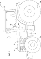
- a work vehicle 50 is shown according to an embodiment.
- the work vehicle 50 is shown as comprising a tractor, it should be noted that, in other embodiments, the work vehicle 50 can vary according to application and/or specification requirements.
- the work vehicle 50 can comprise tracked or unmanned vehicles, and may also comprise road graders, dozers, loaders, excavators, forestry equipment, or turf vehicles, with embodiments discussed herein being merely for exemplary purposes to aid in an understanding of the present disclosure.
- the work vehicle 50 can comprise a vehicle frame 52 supported on a pair of front wheels 56 and rear wheels 58.
- An operator cab 60 can be mounted on a rear region of the vehicle frame 52 and can comprise a variety of controls such as steering wheel 66 to allow a vehicle operator to control functions and operations of the work vehicle 50.
- a user interface 64 can be arranged in the operator cab 60 and can comprise one or more display screens that provide machine data, image data, or selectable menus for controlling various features of the work vehicle 50.
- An engine 62 can be mounted to the vehicle frame 52 within a hood assembly 54 to supply power for all driven components of the work vehicle 50.
- the engine 62 can be configured to drive a transmission (not shown) that drives the rear wheels 58 at various selected speeds in forward or reverse modes.
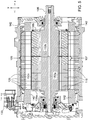
- an electric machine 100 having a cooling system 150 that provides distributed cooling of the electric machine 100 is shown according to an embodiment.
- the electric machine 100 can be arranged within the work vehicle 50.
- the electric machine 100 can be coupled to the engine 62 or transmission of the work vehicle 50.
- the electric machine 100 can comprise a housing 102 encasing a stator assembly 110 and a rotor assembly 108.
- the housing 102 can comprise an outer cylindrical surface 103 having a mounting interface 112 removably coupled to or integrally formed therein.
- An electrical connector 133 can be arranged on the housing 102 to supply three-phase power to the electric machine 100.
- the mounting interface 112 is shown as comprising a plurality of mounting holes 113 which are sized to receive one or more fasteners or similar connectors, in other embodiments, the mounting interface 112 can comprise a variety of coupling features and mechanisms based on the electric machine design.
- the stator assembly 110 can comprise a plurality of stator laminations 120 adjacently arranged to define a stator core 109, with each having generally cylindrical configurations.
- the stator assembly 110 can comprise a solid or split core element, with FIG. 3 being but one exemplary embodiment.
- each of the plurality of stator laminations 120 can comprise n number of slots 122 circumferentially spaced and aligned about an inner surface 124, with each of the slots 122 being dimensioned and sized to accommodate one or more motor windings that extend from the slots 122 to form end turns 142 (refer, e.g., to FIGS. 5 and 6 ).
- one or more weld structures 123 can be formed in or arranged on an outer surface 121 of each of the plurality of stator laminations 120 to provide a more secure bonding connection between the stator laminations 120.
- the rotor assembly 108 can comprise a rotor shaft 104 and, similar to the stator assembly 110, a plurality of stacked laminations (i.e., rotor laminations 118), which are adjacently arranged in compact relation to one another to define a rotor core 107.
- a plurality of stacked laminations i.e., rotor laminations 118
- Each of the plurality of rotor laminations 118 can comprise a shaft receiving opening 114 that is coaxially aligned with an adjacent opening and sized to receive the rotor shaft 104.
- each of the plurality of rotor laminations 118 can comprise one or more field generation structures 126 that are equidistantly spaced and symmetrically arranged relative to one another about each of the rotor laminations 118.
- the one or more field generation structures 126 can comprise at least two cavities 125a, 125b that are sized to receive one or more magnetic elements 106 (e.g., permanent magnets).
- the cavities 125a, 125b can be arranged in a generally v-shaped configuration to allow for the placement of each of the magnetic elements 106 in alternating polarity for the inducement of an alternating magnetic field.
- At least two cooling plates 138a, 138b can be arranged at opposing ends of the rotor core 107 to facilitate cooling of the end turns 142 as coolant exits the rotor assembly 108.
- coolant exiting the rotor core 107 is conveyed through the cooling plates 138a and 138b to the stator windings (not shown) and end turns 142.
- Each of the cooling plates 138a, 138b can be identical and can comprise surface designs including openings and apertures (e.g., 162, 164) that matingly align with those arranged on the rotor laminations 118 (refer, e.g., to FIG. 6 ).
- a spacer disc 116 can be integrally or removably coupled to an end face 128 of one or more of the rotor laminations 118.
- the spacer disc 116 can comprise a plurality of coupling elements 117 that are designed for mating engagement with spacer receiving openings 134 arranged in or on the end face 128.
- the spacer disc 116 can be concentrically arranged relative to the rotor shaft 104 and positioned to cover each of the field generation structures 126.
- the spacer disc 116 is shown as including a generally circular configuration, it should be noted that, in other embodiments, the geometrical configuration of the spacer disc 116 can vary.
- the spacer disc 116 can be sized smaller or larger according to design and specification requirements.
- the cooling system 150 can comprise a plurality of cooling passages 152 arranged in fluid communication with one another to distribute a supply of coolant (e.g., oil or other suitable cooling fluids) through the stator and rotor assemblies 104, 106.
- coolant e.g., oil or other suitable cooling fluids
- each of the plurality of cooling passages 152 can be arranged such that coolant is distributed in a specific direction and through a designated section of the stator and rotor assemblies 106, 108.
- FIGS. 1-5 are provided for illustrative and exemplary purposes only and are in no way intended to limit the present disclosure or its applications.
- the arrangement and/or structural configuration of the electric machine 100 and cooling system 150 can vary.
- the cooling channel 150 can comprise fewer or more cooling passages or distribution channels.
- the internal circuitry and component arrangement of the electric machine 100 can vary according to design and/or specification requirements.
- the plurality of cooling passages 152 can comprise a first passage 152a, a second passage 152b, and a third passage 152c, which are intersectionally arranged to define a continuous flow path through the electric machine 100.
- the first passage 152a can be arranged to extend axially, relative to the center axis 101, along a partial or full length of the rotor shaft 104 between a first end 154 and a second end 156 in some embodiments.
- the first passage 152a can receive a supply of coolant from an inlet 153 arranged in a rear cover 103 of the housing 102 ( FIG. 5 ).
- the supply of coolant moves through the rotor shaft 104 in a first direction (e.g., an x-direction) and is distributed to the second passage 152b via an orifice 155 at the second end 156.
- the second passage 152b can be centrally arranged to extend radially through the rotor shaft 104 in a second direction orthogonal to the first direction.
- the second passage 152b can be arranged to extend through at least one side-wall of the rotor shaft 104 in a direction (e.g., y-direction) generally perpendicular to the center axis 101.
- the direction and/or angular orientation of the second passage may vary according to application and specification requirements.
- the second passage 152b can be arranged to communicate with the first passage 152a at a receiving end 158 and the third passage 152c at a distributing end 160.
- the second passage 152b can be arranged such that coolant received from the receiving end 158 is directed into the third passage 152c for distribution through the plurality of rotor laminations 118 at the distributing end 160.
- the width and length of the second passage 152b can be sized generally less than each of the first and third passages 152a, 152c to allow for more controlled flow distribution.
- the second passage 152b is shown as being centrally arranged on one side of the rotor shaft 104, it should be noted that, in other embodiments, the position and orientation of the second passage 152b may vary.
- the second passage 152b can be arranged on opposing sides of the rotor shaft 104, and/or its channel size and length can be increased or decreased.
- the second passage 152b can comprise two or more passages relatively arranged to extend in a radial or axial direction of the rotor shaft 104.
- the third passage 152c can be arranged to extend in a third direction, which, in some embodiments, may also be orthogonal to the second direction, through the plurality of rotor laminations 118.
- the third passage 152c can comprise a plurality of coaxially aligned apertures 132 that are arranged in each of the plurality of rotor laminations 118 to form the continuous flow passage (i.e., third passage 152c).
- the third passage 152c can comprise a plurality of passages equidistantly spaced relative to one another in a generally circular configuration about the rotor assembly 108.
- the third passage 152c can be formed as an integral channel and may also be arranged in various positional and/or angular orientations, with embodiments herein being merely exemplary embodiments.
- third passage 152c is particularly advantageous in that it allows for the coolant to be distributed through the rotor laminations 118 and to the magnetic elements 106 arranged in the cavities 125a, 125b.
- the spacer disc 116 is arranged such that radial flow of coolant from the third passage 152c is impeded and directed into each of the apertures 132 to allow for cooling of the magnetic elements 106 as shown in FIG. 8 .
- each of the cooling plates 138a, 138b can comprise a thin plate such as that shown in FIG. 6 .
- the cooling plates can include cooling plates 238a, 238b, each having a lipped portion 270, apertures/openings 262, 264, 266, and a shaft opening 268 that is sized to encircle the rotor shaft 204 as shown in FIGS. 7A and 7B .
- the lipped portion 270 can be designed to extend outwardly and away from an outer periphery of each of the cooling plates 238a, 238b, and may vary in length in various embodiments. For example, in some embodiments, the length of the lipped portion 270 can be decreased or extended to change the location at which coolant exiting the third passage 152c strikes the end turn 142.
- a plurality of external flow passages as indicated by the arrows 166 can be arranged in fluid communication with the third passage 152c to provide a path for coolant to flow from the third passage 152c to the plurality of stator laminations 120 via an air gap 140. This, in turn, minimizes the amount of coolant distributed to the stator laminations 120 while allowing for some leakage to occur.
- a technical effect of one or more of the example embodiments disclosed herein is a cooling system and method for an electric machine.
- the cooling system is particularly advantageous in that it allows for distributed cooling of the electric machine to dissipate heat accumulated in the electric machine and to improve machine performance.
Landscapes
- Engineering & Computer Science (AREA)
- Power Engineering (AREA)
- Chemical & Material Sciences (AREA)
- Combustion & Propulsion (AREA)
- Transportation (AREA)
- Mechanical Engineering (AREA)
- Motor Or Generator Cooling System (AREA)
- Iron Core Of Rotating Electric Machines (AREA)
Abstract
Description
- The present disclosure relates generally to electric machine cooling systems, and, more particularly, to a cooling system and method that provides distributed cooling of an electric machine.
- In high performance electric machine applications, effective thermal management is critical in ensuring optimal machine performance. Increased power densities and efficiency requirements of electric machines lead to increases in heat densities that result in undesirable thermal conditions. For example, excessive heat generation resulting from losses within the stator windings, laminations, or magnets is distributed to a variety of machine components, which causes adverse temperature effects. These temperature effects can include magnet demagnetization, component failure, as well as insulation damage of the machine.
- To address such concerns and to enhance thermal designs of the electric machines, a variety of conventional cooling techniques have been employed. For example, some conventional approaches employ the use of passive cooling techniques such as rotor rotation, convection cooling, or fin cooling to reduce adverse temperature effects within the electric machine. Other approaches employ active cooling techniques such as fan or air cooling to enhance heat transfer.
- Drawbacks to such approaches include inefficient and limited cooling of the electric machines, restricted heat transfer, degraded system performance. Therefore, to overcome the drawbacks of conventional techniques, there is a need in the art for a more robust and improved cooling design to more effectively cool electric machines and increase system performance.
- According to an aspect of the present disclosure, an electric machine with distributed cooling is disclosed. The electric machine includes a stator assembly, a rotor assembly including a rotor shaft and a rotor core, and a distributed cooling system. The distributed cooling system including at least one inlet arranged on an end of the rotor shaft, a first passage, a second passage, and at least one third passage. The first passage extends axially in a first direction through at least a portion of the rotor shaft to direct a flow of coolant received from the inlet in the first direction. The second passage is fluidly coupled to the first passage and extends in a second direction through at least a portion of the rotor shaft between a receiving end and a distributing end. The second passage is configured to direct the flow of coolant in the second direction for distribution at the distributing end. The at least one third passage fluidly coupled to the second passage, the at least one third passage extending between a first end and a second end, wherein the third passage is configured to distribute coolant received from the second passage to at least one of the first end or the second end into the stator assembly.
- According to another aspect of the present disclosure, a work vehicle is disclosed. The work vehicle includes a vehicle frame, an engine, a transmission; and an electric machine operatively coupled to at least one of the engine or transmission. The electric machine includes a stator assembly, a rotor assembly having a rotor core and a rotor shaft, and a distributed cooling system. The distributed cooling system including at least one inlet arranged on an end of the rotor shaft, a first passage, a second passage, and at least one third passage. The first passage extending axially in a first direction through at least a portion of the rotor shaft to direct a flow of coolant received from the inlet in the first direction. The second passage fluidly coupled to the first passage and extends in a second direction through at least a portion of the rotor shaft between a receiving end and a distributing end. The second passage is configured to direct the flow of coolant in the second direction for distribution at the distributing end. The at least one third passage fluidly coupled to the second passage, the at least one third passage extending between a first end and a second end, wherein the third passage is configured to distribute coolant received from the second passage to at least one of the first end or the second end into the stator assembly.
- Other features and aspects will become apparent by consideration of the detailed description and accompanying drawings.
- The detailed description of the drawings refers to the accompanying figures in which:
-
FIG. 1 is a side view of a work vehicle according to an embodiment; -
FIG. 2 is a cross-sectional view of an electric machine according to an embodiment; -
FIG. 3 is an expanded perspective view of the electric machine ofFIG. 1 according to an embodiment; -
FIG. 4 is a side cross-sectional view of the electric machine ofFIG. 1 according to an embodiment; -
FIG. 5 is a perspective cross-sectional view of the electric machine ofFIG. 1 according to an embodiment; -
FIG. 7A is a perspective view of a cooling plate according to an embodiment; -
FIG. 7B is a perspective cross-sectional view of an electric machine according to an embodiment; and -
FIG. 8 is a side cross-sectional view of the electric machine ofFIG. 1 according to an embodiment. - Like reference numerals are used to indicate like elements through the several figures.
- Referring to
FIG. 1 , awork vehicle 50 is shown according to an embodiment. Although inFIG. 1 thework vehicle 50 is shown as comprising a tractor, it should be noted that, in other embodiments, thework vehicle 50 can vary according to application and/or specification requirements. For example, in other embodiments, thework vehicle 50 can comprise tracked or unmanned vehicles, and may also comprise road graders, dozers, loaders, excavators, forestry equipment, or turf vehicles, with embodiments discussed herein being merely for exemplary purposes to aid in an understanding of the present disclosure. - As shown in
FIG. 1 , thework vehicle 50 can comprise avehicle frame 52 supported on a pair offront wheels 56 andrear wheels 58. Anoperator cab 60 can be mounted on a rear region of thevehicle frame 52 and can comprise a variety of controls such assteering wheel 66 to allow a vehicle operator to control functions and operations of thework vehicle 50. Auser interface 64 can be arranged in theoperator cab 60 and can comprise one or more display screens that provide machine data, image data, or selectable menus for controlling various features of thework vehicle 50. Anengine 62 can be mounted to thevehicle frame 52 within ahood assembly 54 to supply power for all driven components of thework vehicle 50. For example, theengine 62 can be configured to drive a transmission (not shown) that drives therear wheels 58 at various selected speeds in forward or reverse modes. - Referring to
FIGS. 2-5 , anelectric machine 100 having acooling system 150 that provides distributed cooling of theelectric machine 100 is shown according to an embodiment. Theelectric machine 100 can be arranged within thework vehicle 50. For example, in some embodiments, theelectric machine 100 can be coupled to theengine 62 or transmission of thework vehicle 50. Theelectric machine 100 can comprise ahousing 102 encasing astator assembly 110 and arotor assembly 108. Thehousing 102 can comprise an outercylindrical surface 103 having amounting interface 112 removably coupled to or integrally formed therein. Anelectrical connector 133 can be arranged on thehousing 102 to supply three-phase power to theelectric machine 100. Although inFIG. 2 , themounting interface 112 is shown as comprising a plurality ofmounting holes 113 which are sized to receive one or more fasteners or similar connectors, in other embodiments, themounting interface 112 can comprise a variety of coupling features and mechanisms based on the electric machine design. - In some embodiments, the
stator assembly 110 can comprise a plurality ofstator laminations 120 adjacently arranged to define astator core 109, with each having generally cylindrical configurations. In other embodiments, thestator assembly 110 can comprise a solid or split core element, withFIG. 3 being but one exemplary embodiment. As shown inFIG. 3 , each of the plurality ofstator laminations 120 can comprise n number ofslots 122 circumferentially spaced and aligned about aninner surface 124, with each of theslots 122 being dimensioned and sized to accommodate one or more motor windings that extend from theslots 122 to form end turns 142 (refer, e.g., toFIGS. 5 and6 ). In some embodiments, one or moreweld structures 123 can be formed in or arranged on anouter surface 121 of each of the plurality ofstator laminations 120 to provide a more secure bonding connection between thestator laminations 120. - The
rotor assembly 108 can comprise arotor shaft 104 and, similar to thestator assembly 110, a plurality of stacked laminations (i.e., rotor laminations 118), which are adjacently arranged in compact relation to one another to define arotor core 107. Each of the plurality ofrotor laminations 118 can comprise a shaft receiving opening 114 that is coaxially aligned with an adjacent opening and sized to receive therotor shaft 104. Additionally, each of the plurality ofrotor laminations 118 can comprise one or morefield generation structures 126 that are equidistantly spaced and symmetrically arranged relative to one another about each of therotor laminations 118. The one or morefield generation structures 126 can comprise at least twocavities FIG. 3 , thecavities magnetic elements 106 in alternating polarity for the inducement of an alternating magnetic field. - As shown in
FIG. 5 , at least two coolingplates rotor core 107 to facilitate cooling of the end turns 142 as coolant exits therotor assembly 108. For example, coolant exiting therotor core 107 is conveyed through thecooling plates cooling plates FIG. 6 ). - In some embodiments, a
spacer disc 116 can be integrally or removably coupled to anend face 128 of one or more of therotor laminations 118. For example, thespacer disc 116 can comprise a plurality ofcoupling elements 117 that are designed for mating engagement with spacer receiving openings 134 arranged in or on theend face 128. As shown inFIG. 3 , thespacer disc 116 can be concentrically arranged relative to therotor shaft 104 and positioned to cover each of thefield generation structures 126. Although in embodiments herein, thespacer disc 116 is shown as including a generally circular configuration, it should be noted that, in other embodiments, the geometrical configuration of thespacer disc 116 can vary. For example, in other embodiments, thespacer disc 116 can be sized smaller or larger according to design and specification requirements. - The
cooling system 150 can comprise a plurality of cooling passages 152 arranged in fluid communication with one another to distribute a supply of coolant (e.g., oil or other suitable cooling fluids) through the stator androtor assemblies FIGS. 6-8 , each of the plurality of cooling passages 152 can be arranged such that coolant is distributed in a specific direction and through a designated section of the stator androtor assemblies - As will be appreciated by those skilled in the art,
FIGS. 1-5 are provided for illustrative and exemplary purposes only and are in no way intended to limit the present disclosure or its applications. In other embodiments, the arrangement and/or structural configuration of theelectric machine 100 andcooling system 150 can vary. For example, in some embodiments, the coolingchannel 150 can comprise fewer or more cooling passages or distribution channels. Additionally, in other embodiments, the internal circuitry and component arrangement of theelectric machine 100 can vary according to design and/or specification requirements. - Referring now to
FIGS. 6-8 , a more detailed view of thecooling system 150 is shown. In some embodiments, the plurality of cooling passages 152 can comprise afirst passage 152a, asecond passage 152b, and athird passage 152c, which are intersectionally arranged to define a continuous flow path through theelectric machine 100. Thefirst passage 152a can be arranged to extend axially, relative to the center axis 101, along a partial or full length of therotor shaft 104 between afirst end 154 and asecond end 156 in some embodiments. At thefirst end 154, thefirst passage 152a can receive a supply of coolant from aninlet 153 arranged in arear cover 103 of the housing 102 (FIG. 5 ). The supply of coolant moves through therotor shaft 104 in a first direction (e.g., an x-direction) and is distributed to thesecond passage 152b via anorifice 155 at thesecond end 156. - In some embodiments, the
second passage 152b can be centrally arranged to extend radially through therotor shaft 104 in a second direction orthogonal to the first direction. For example, in some embodiments, thesecond passage 152b can be arranged to extend through at least one side-wall of therotor shaft 104 in a direction (e.g., y-direction) generally perpendicular to the center axis 101. In other embodiments, the direction and/or angular orientation of the second passage may vary according to application and specification requirements. As shown inFIG. 6 , thesecond passage 152b can be arranged to communicate with thefirst passage 152a at a receivingend 158 and thethird passage 152c at a distributingend 160. For example, thesecond passage 152b can be arranged such that coolant received from the receivingend 158 is directed into thethird passage 152c for distribution through the plurality ofrotor laminations 118 at the distributingend 160. - In some embodiments, the width and length of the
second passage 152b can be sized generally less than each of the first andthird passages second passage 152b is shown as being centrally arranged on one side of therotor shaft 104, it should be noted that, in other embodiments, the position and orientation of thesecond passage 152b may vary. For example, in other embodiments, thesecond passage 152b can be arranged on opposing sides of therotor shaft 104, and/or its channel size and length can be increased or decreased. In still other embodiments, thesecond passage 152b can comprise two or more passages relatively arranged to extend in a radial or axial direction of therotor shaft 104. - The
third passage 152c can be arranged to extend in a third direction, which, in some embodiments, may also be orthogonal to the second direction, through the plurality ofrotor laminations 118. Thethird passage 152c can comprise a plurality of coaxially alignedapertures 132 that are arranged in each of the plurality ofrotor laminations 118 to form the continuous flow passage (i.e.,third passage 152c). Additionally, referring now back toFIG. 4 , in some embodiments, thethird passage 152c can comprise a plurality of passages equidistantly spaced relative to one another in a generally circular configuration about therotor assembly 108. In other embodiments, thethird passage 152c can be formed as an integral channel and may also be arranged in various positional and/or angular orientations, with embodiments herein being merely exemplary embodiments. - The arrangement of
third passage 152c is particularly advantageous in that it allows for the coolant to be distributed through therotor laminations 118 and to themagnetic elements 106 arranged in thecavities second passage 152b and enters thethird passage 152c, thespacer disc 116 is arranged such that radial flow of coolant from thethird passage 152c is impeded and directed into each of theapertures 132 to allow for cooling of themagnetic elements 106 as shown inFIG. 8 . - Additionally, referring now to
FIGS. 6-7B , the cooling is further enhanced due to the arrangement of thecooling plates cooling plates third passage 152b via theapertures 132. In some embodiments, each of thecooling plates FIG. 6 . In other embodiments, the cooling plates can includecooling plates lipped portion 270, apertures/openings shaft opening 268 that is sized to encircle therotor shaft 204 as shown inFIGS. 7A and7B . Thelipped portion 270 can be designed to extend outwardly and away from an outer periphery of each of thecooling plates lipped portion 270 can be decreased or extended to change the location at which coolant exiting thethird passage 152c strikes theend turn 142. - As shown in
FIGS. 6 and7B , a plurality of external flow passages as indicated by thearrows 166 can be arranged in fluid communication with thethird passage 152c to provide a path for coolant to flow from thethird passage 152c to the plurality ofstator laminations 120 via anair gap 140. This, in turn, minimizes the amount of coolant distributed to thestator laminations 120 while allowing for some leakage to occur. - Without in any way limiting the scope, interpretation, or application of the claims appearing below, a technical effect of one or more of the example embodiments disclosed herein is a cooling system and method for an electric machine. The cooling system is particularly advantageous in that it allows for distributed cooling of the electric machine to dissipate heat accumulated in the electric machine and to improve machine performance.
- While the above describes example embodiments of the present disclosure, these descriptions should not be viewed in a limiting sense. Rather, other variations and modifications may be made without departing from the scope and spirit of the present disclosure as defined in the appended claims.
Claims (9)
- An electric machine (100) with distributed cooling, the electric machine (100) comprising:a stator assembly (110);a rotor assembly (108) comprising a rotor shaft (104) and a rotor core (107); anda distributed cooling system (150) comprising:at least one inlet (153) arranged on an end of the rotor shaft (104);a first passage (152a, 252a) extending axially in a first direction through at least a portion of the rotor shaft (104), wherein the first passage (152a, 252a) is configured to direct a flow of coolant received from the inlet (153) in the first direction;a second passage (152b, 252b) fluidly coupled to the first passage (152a, 252a), the second passage (152b, 252b) extending in a second direction through at least a portion of the rotor shaft (104) between a receiving end (158) and a distributing end (160), wherein the second passage (152b, 252b) is configured to direct the flow of coolant in the second direction for distribution at the distributing end (160); andat least one third passage (152c, 252c) fluidly coupled to the second passage (152b, 252b), the at least one third passage (152c, 252c) extending between a first end and a second end, wherein the third passage (152c, 252c) is configured to distribute coolant received from the second passage (152b, 252b) to at least one of the first end or the second end into the stator assembly (110).
- The electric machine (100) of claim 1, wherein the rotor core (107) comprises a plurality of rotor laminations (118) arranged in stacked relation to one another with each having a center opening sized to receive the rotor shaft (104).
- The electric machine (100) of claim 2, wherein each of the plurality of rotor laminations (118) comprises one or more field generation structures having cavities (125a, 125b) sized to receive one or more magnetic elements (106).
- The electric machine (100) of claim 3, wherein a spacer disc (116) removably or integrally coupled to an end face of each of the plurality of rotor laminations (118), and wherein the spacer disc (116) is configured to impede radial distribution of coolant from the third passage (152c, 252c) to provide coolant to the one or more magnetic elements (106).
- The electric machine (100) of claim 1, wherein the second direction is orthogonal to the first direction and the third direction.
- The electric machine (100) of claim 1, wherein the at least one third passage (152c, 252c) is defined by at least two or more coaxially aligned apertures (132) respectively arranged in adjacent laminations (118) of the plurality of rotor laminations (118), and wherein the at least one third passage (152c, 252c) comprises a plurality of third passages (152c, 252c).
- The electric machine (100) of claim 1, wherein the rotor assembly (108) further comprises at least two cooling plates (138a, 138b) arranged at opposing ends of the rotor assembly (108), and wherein the at least two cooling plates (138a, 138b) comprise one or more apertures (262, 264, 266) arranged in axial alignment with the third passage (152c, 252c) such that coolant exiting the third passage (152c, 252c) is directed to one or more end turns arranged in the stator assembly (110).
- The electric machine (100) of claim 7, wherein each of the at least two cooling plates (138a, 138b) further comprises a lipped portion (270) that extends outwardly and away from an outer periphery of each of the cooling plates (138a, 138b).
- A work vehicle (50), the work vehicle (50) comprising:a vehicle frame (52);an engine (62);a transmission; andan electric machine (100) according to one of the preceding claims operatively coupled to the transmission.
Applications Claiming Priority (1)
| Application Number | Priority Date | Filing Date | Title |
|---|---|---|---|
| US201962889258P | 2019-08-20 | 2019-08-20 |
Publications (2)
| Publication Number | Publication Date |
|---|---|
| EP3783775A1 true EP3783775A1 (en) | 2021-02-24 |
| EP3783775B1 EP3783775B1 (en) | 2023-08-23 |
Family
ID=71950529
Family Applications (1)
| Application Number | Title | Priority Date | Filing Date |
|---|---|---|---|
| EP20189638.8A Active EP3783775B1 (en) | 2019-08-20 | 2020-08-05 | Electric machine distributed cooling system and method |
Country Status (4)
| Country | Link |
|---|---|
| US (1) | US11509178B2 (en) |
| EP (1) | EP3783775B1 (en) |
| CN (1) | CN112421832A (en) |
| CA (1) | CA3086316A1 (en) |
Families Citing this family (2)
| Publication number | Priority date | Publication date | Assignee | Title |
|---|---|---|---|---|
| SE546445C2 (en) * | 2021-04-28 | 2024-11-05 | Scania Cv Ab | An electric rotating machine with a fluid-guiding member for removing fluid from the rotor compartment |
| CN113682397A (en) * | 2021-09-30 | 2021-11-23 | 深圳鹏行智能研究有限公司 | Power module and power equipment |
Citations (2)
| Publication number | Priority date | Publication date | Assignee | Title |
|---|---|---|---|---|
| DE112012000077T5 (en) * | 2011-03-02 | 2013-06-06 | Komatsu Ltd. | Engine cooling structure and engine |
| DE102017202752A1 (en) * | 2017-02-21 | 2018-08-23 | Continental Automotive Gmbh | Rotor for an electric machine |
Family Cites Families (24)
| Publication number | Priority date | Publication date | Assignee | Title |
|---|---|---|---|---|
| SE318939B (en) * | 1965-03-17 | 1969-12-22 | Asea Ab | |
| US5703421A (en) * | 1996-05-24 | 1997-12-30 | The United States Of America As Represented By The Secretary Of The Air Force | Reluctance generator/motor cooling |
| GB2313411B (en) | 1996-05-25 | 1999-10-13 | Concentric Pumps Ltd | Improvements in drive systems |
| US6239520B1 (en) | 2000-04-24 | 2001-05-29 | Capstone Turbine Corporation | Permanent magnet rotor cooling system and method |
| CN1258254C (en) | 2002-04-01 | 2006-05-31 | 日产自动车株式会社 | Stator cooling structure for multi-axis and multi-layer motors |
| US7009317B2 (en) | 2004-01-14 | 2006-03-07 | Caterpillar Inc. | Cooling system for an electric motor |
| DE102004049795A1 (en) | 2004-04-08 | 2005-11-10 | Deere & Company, Moline | Cooling device for electrical machine, has feeding apparatus through which coolant is directed from one zone of rotor in electrical machine to another zone of rotor when rotor rotates |
| US7462963B2 (en) | 2004-11-30 | 2008-12-09 | Nissan Motor Co., Ltd. | Motor cooling device and cooling method |
| US7591147B2 (en) | 2006-11-01 | 2009-09-22 | Honeywell International Inc. | Electric motor cooling jacket resistor |
| US7675209B2 (en) | 2007-02-01 | 2010-03-09 | Honeywell International Inc. | Electric motor cooling jacket |
| WO2011163226A2 (en) * | 2010-06-21 | 2011-12-29 | Nidec Motor Corporation | Electric motor assemblies including stator and/or rotor cooling |
| US8729751B2 (en) | 2010-11-10 | 2014-05-20 | Hamilton Sundstrand Corporation | Heat transfer assembly for electric motor rotor |
| US8604651B2 (en) | 2011-02-18 | 2013-12-10 | Hamilton Sundstrand Space Systems International, Inc. | Cooling of permanent magnet electric machine |
| US20120318479A1 (en) | 2011-06-14 | 2012-12-20 | Fukuta Electric & Machinery Co., Ltd. | Liquid cooled motor assembly and cover thereof |
| US8896167B2 (en) * | 2012-05-25 | 2014-11-25 | Deere & Company | Electric machine rotor cooling method |
| US8970075B2 (en) | 2012-08-08 | 2015-03-03 | Ac Propulsion, Inc. | Liquid cooled electric motor |
| DE102012223372A1 (en) | 2012-12-17 | 2014-06-18 | Zf Friedrichshafen Ag | Electric machine i.e. inner rotor-motor, for hybrid drive arrangement for vehicle, has stator with stator carrier, and coolant supply element discharging coolant from coolant channel and arranged axially at radial outer edge of carrier |
| JP5913160B2 (en) * | 2013-03-11 | 2016-04-27 | トヨタ自動車株式会社 | Rotating electric machine rotor and rotating electric machine |
| US10483812B2 (en) * | 2014-12-31 | 2019-11-19 | Ingersoll-Rand Company | Electrical machine and method of manufacture |
| US9793767B2 (en) | 2015-03-19 | 2017-10-17 | Hamilton Sundstrand Corporation | Method and assembly for cooling an electric machine |
| WO2016206342A1 (en) | 2015-06-23 | 2016-12-29 | 戴杰 | Self-circulation liquid-cooled permanent magnet motor |
| US10038355B2 (en) * | 2015-07-08 | 2018-07-31 | Caterpillar Inc. | Electric machine having rotor and stator cooling assembly |
| CN205565915U (en) * | 2016-02-24 | 2016-09-07 | 南通杰夫电气有限公司 | Do benefit to refrigerated motor stator structure |
| US11011955B2 (en) | 2017-03-28 | 2021-05-18 | Lg Electronics Inc. | Motor |
-
2019
- 2019-09-13 US US16/570,416 patent/US11509178B2/en active Active
-
2020
- 2020-07-09 CA CA3086316A patent/CA3086316A1/en active Pending
- 2020-07-20 CN CN202010701752.6A patent/CN112421832A/en active Pending
- 2020-08-05 EP EP20189638.8A patent/EP3783775B1/en active Active
Patent Citations (2)
| Publication number | Priority date | Publication date | Assignee | Title |
|---|---|---|---|---|
| DE112012000077T5 (en) * | 2011-03-02 | 2013-06-06 | Komatsu Ltd. | Engine cooling structure and engine |
| DE102017202752A1 (en) * | 2017-02-21 | 2018-08-23 | Continental Automotive Gmbh | Rotor for an electric machine |
Also Published As
| Publication number | Publication date |
|---|---|
| CN112421832A (en) | 2021-02-26 |
| US20210057948A1 (en) | 2021-02-25 |
| CA3086316A1 (en) | 2021-02-20 |
| US11509178B2 (en) | 2022-11-22 |
| EP3783775B1 (en) | 2023-08-23 |
Similar Documents
| Publication | Publication Date | Title |
|---|---|---|
| EP4236036B1 (en) | Motor, power assembly and apparatus | |
| US12142967B2 (en) | Electric machine with integrated dam assembly | |
| EP4138274A1 (en) | Electric motor rotor, electric motor, and vehicle | |
| EP4044404B1 (en) | A concentrated winding axial cooling motor stator and motor | |
| US10749411B2 (en) | Rotary electric machine | |
| EP3783775B1 (en) | Electric machine distributed cooling system and method | |
| EP3993236A1 (en) | Liquid-cooled motor | |
| US12113400B2 (en) | Rotor, rotary electric machine, and drive apparatus | |
| CN115864747A (en) | Oil-cooled electric motors, powertrains and vehicles | |
| EP4195456B1 (en) | Stator core | |
| EP4622069A1 (en) | Axial magnetic field motor and cooling structure thereof | |
| JP2013135539A (en) | Electric motor and laminate stator | |
| US20230412019A1 (en) | Rotating electric machine and drive device | |
| CN115051509A (en) | Rotating electric machine and drive device | |
| US20220181934A1 (en) | Electric machine rotor cooling | |
| WO2025232346A1 (en) | Rotor core, motor rotor, motor, and automobile | |
| WO2026000856A1 (en) | Electric motor | |
| JP6973116B2 (en) | Motor cooling structure | |
| WO2020214939A1 (en) | Heat transfer array and the electric machine made therewith | |
| CN113708550B (en) | Electric machine | |
| JP2025002962A (en) | Rotating electric machine stator | |
| WO2022052848A1 (en) | A rotary electric machine, a powertrain assembley and an electrified vehicle | |
| KR20240036189A (en) | Motor having cooling flow path | |
| KR20190142184A (en) | Electric motor | |
| CN223912336U (en) | Dual rotor motors and vehicle power systems |
Legal Events
| Date | Code | Title | Description |
|---|---|---|---|
| PUAI | Public reference made under article 153(3) epc to a published international application that has entered the european phase |
Free format text: ORIGINAL CODE: 0009012 |
|
| STAA | Information on the status of an ep patent application or granted ep patent |
Free format text: STATUS: THE APPLICATION HAS BEEN PUBLISHED |
|
| AK | Designated contracting states |
Kind code of ref document: A1 Designated state(s): AL AT BE BG CH CY CZ DE DK EE ES FI FR GB GR HR HU IE IS IT LI LT LU LV MC MK MT NL NO PL PT RO RS SE SI SK SM TR |
|
| AX | Request for extension of the european patent |
Extension state: BA ME |
|
| STAA | Information on the status of an ep patent application or granted ep patent |
Free format text: STATUS: REQUEST FOR EXAMINATION WAS MADE |
|
| 17P | Request for examination filed |
Effective date: 20210824 |
|
| RBV | Designated contracting states (corrected) |
Designated state(s): AL AT BE BG CH CY CZ DE DK EE ES FI FR GB GR HR HU IE IS IT LI LT LU LV MC MK MT NL NO PL PT RO RS SE SI SK SM TR |
|
| STAA | Information on the status of an ep patent application or granted ep patent |
Free format text: STATUS: EXAMINATION IS IN PROGRESS |
|
| 17Q | First examination report despatched |
Effective date: 20211027 |
|
| GRAP | Despatch of communication of intention to grant a patent |
Free format text: ORIGINAL CODE: EPIDOSNIGR1 |
|
| STAA | Information on the status of an ep patent application or granted ep patent |
Free format text: STATUS: GRANT OF PATENT IS INTENDED |
|
| INTG | Intention to grant announced |
Effective date: 20230405 |
|
| GRAS | Grant fee paid |
Free format text: ORIGINAL CODE: EPIDOSNIGR3 |
|
| GRAA | (expected) grant |
Free format text: ORIGINAL CODE: 0009210 |
|
| STAA | Information on the status of an ep patent application or granted ep patent |
Free format text: STATUS: THE PATENT HAS BEEN GRANTED |
|
| AK | Designated contracting states |
Kind code of ref document: B1 Designated state(s): AL AT BE BG CH CY CZ DE DK EE ES FI FR GB GR HR HU IE IS IT LI LT LU LV MC MK MT NL NO PL PT RO RS SE SI SK SM TR |
|
| REG | Reference to a national code |
Ref country code: GB Ref legal event code: FG4D |
|
| REG | Reference to a national code |
Ref country code: CH Ref legal event code: EP |
|
| REG | Reference to a national code |
Ref country code: IE Ref legal event code: FG4D |
|
| REG | Reference to a national code |
Ref country code: DE Ref legal event code: R096 Ref document number: 602020016111 Country of ref document: DE |
|
| REG | Reference to a national code |
Ref country code: LT Ref legal event code: MG9D |
|
| REG | Reference to a national code |
Ref country code: NL Ref legal event code: MP Effective date: 20230823 |
|
| REG | Reference to a national code |
Ref country code: AT Ref legal event code: MK05 Ref document number: 1603727 Country of ref document: AT Kind code of ref document: T Effective date: 20230823 |
|
| PG25 | Lapsed in a contracting state [announced via postgrant information from national office to epo] |
Ref country code: GR Free format text: LAPSE BECAUSE OF FAILURE TO SUBMIT A TRANSLATION OF THE DESCRIPTION OR TO PAY THE FEE WITHIN THE PRESCRIBED TIME-LIMIT Effective date: 20231124 |
|
| PG25 | Lapsed in a contracting state [announced via postgrant information from national office to epo] |
Ref country code: IS Free format text: LAPSE BECAUSE OF FAILURE TO SUBMIT A TRANSLATION OF THE DESCRIPTION OR TO PAY THE FEE WITHIN THE PRESCRIBED TIME-LIMIT Effective date: 20231223 |
|
| PG25 | Lapsed in a contracting state [announced via postgrant information from national office to epo] |
Ref country code: SE Free format text: LAPSE BECAUSE OF FAILURE TO SUBMIT A TRANSLATION OF THE DESCRIPTION OR TO PAY THE FEE WITHIN THE PRESCRIBED TIME-LIMIT Effective date: 20230823 Ref country code: RS Free format text: LAPSE BECAUSE OF FAILURE TO SUBMIT A TRANSLATION OF THE DESCRIPTION OR TO PAY THE FEE WITHIN THE PRESCRIBED TIME-LIMIT Effective date: 20230823 Ref country code: PT Free format text: LAPSE BECAUSE OF FAILURE TO SUBMIT A TRANSLATION OF THE DESCRIPTION OR TO PAY THE FEE WITHIN THE PRESCRIBED TIME-LIMIT Effective date: 20231226 Ref country code: NO Free format text: LAPSE BECAUSE OF FAILURE TO SUBMIT A TRANSLATION OF THE DESCRIPTION OR TO PAY THE FEE WITHIN THE PRESCRIBED TIME-LIMIT Effective date: 20231123 Ref country code: NL Free format text: LAPSE BECAUSE OF FAILURE TO SUBMIT A TRANSLATION OF THE DESCRIPTION OR TO PAY THE FEE WITHIN THE PRESCRIBED TIME-LIMIT Effective date: 20230823 Ref country code: LV Free format text: LAPSE BECAUSE OF FAILURE TO SUBMIT A TRANSLATION OF THE DESCRIPTION OR TO PAY THE FEE WITHIN THE PRESCRIBED TIME-LIMIT Effective date: 20230823 Ref country code: LT Free format text: LAPSE BECAUSE OF FAILURE TO SUBMIT A TRANSLATION OF THE DESCRIPTION OR TO PAY THE FEE WITHIN THE PRESCRIBED TIME-LIMIT Effective date: 20230823 Ref country code: IS Free format text: LAPSE BECAUSE OF FAILURE TO SUBMIT A TRANSLATION OF THE DESCRIPTION OR TO PAY THE FEE WITHIN THE PRESCRIBED TIME-LIMIT Effective date: 20231223 Ref country code: HR Free format text: LAPSE BECAUSE OF FAILURE TO SUBMIT A TRANSLATION OF THE DESCRIPTION OR TO PAY THE FEE WITHIN THE PRESCRIBED TIME-LIMIT Effective date: 20230823 Ref country code: GR Free format text: LAPSE BECAUSE OF FAILURE TO SUBMIT A TRANSLATION OF THE DESCRIPTION OR TO PAY THE FEE WITHIN THE PRESCRIBED TIME-LIMIT Effective date: 20231124 Ref country code: FI Free format text: LAPSE BECAUSE OF FAILURE TO SUBMIT A TRANSLATION OF THE DESCRIPTION OR TO PAY THE FEE WITHIN THE PRESCRIBED TIME-LIMIT Effective date: 20230823 Ref country code: AT Free format text: LAPSE BECAUSE OF FAILURE TO SUBMIT A TRANSLATION OF THE DESCRIPTION OR TO PAY THE FEE WITHIN THE PRESCRIBED TIME-LIMIT Effective date: 20230823 |
|
| PG25 | Lapsed in a contracting state [announced via postgrant information from national office to epo] |
Ref country code: PL Free format text: LAPSE BECAUSE OF FAILURE TO SUBMIT A TRANSLATION OF THE DESCRIPTION OR TO PAY THE FEE WITHIN THE PRESCRIBED TIME-LIMIT Effective date: 20230823 |
|
| PG25 | Lapsed in a contracting state [announced via postgrant information from national office to epo] |
Ref country code: ES Free format text: LAPSE BECAUSE OF FAILURE TO SUBMIT A TRANSLATION OF THE DESCRIPTION OR TO PAY THE FEE WITHIN THE PRESCRIBED TIME-LIMIT Effective date: 20230823 |
|
| PG25 | Lapsed in a contracting state [announced via postgrant information from national office to epo] |
Ref country code: SM Free format text: LAPSE BECAUSE OF FAILURE TO SUBMIT A TRANSLATION OF THE DESCRIPTION OR TO PAY THE FEE WITHIN THE PRESCRIBED TIME-LIMIT Effective date: 20230823 Ref country code: RO Free format text: LAPSE BECAUSE OF FAILURE TO SUBMIT A TRANSLATION OF THE DESCRIPTION OR TO PAY THE FEE WITHIN THE PRESCRIBED TIME-LIMIT Effective date: 20230823 Ref country code: ES Free format text: LAPSE BECAUSE OF FAILURE TO SUBMIT A TRANSLATION OF THE DESCRIPTION OR TO PAY THE FEE WITHIN THE PRESCRIBED TIME-LIMIT Effective date: 20230823 Ref country code: EE Free format text: LAPSE BECAUSE OF FAILURE TO SUBMIT A TRANSLATION OF THE DESCRIPTION OR TO PAY THE FEE WITHIN THE PRESCRIBED TIME-LIMIT Effective date: 20230823 Ref country code: DK Free format text: LAPSE BECAUSE OF FAILURE TO SUBMIT A TRANSLATION OF THE DESCRIPTION OR TO PAY THE FEE WITHIN THE PRESCRIBED TIME-LIMIT Effective date: 20230823 Ref country code: CZ Free format text: LAPSE BECAUSE OF FAILURE TO SUBMIT A TRANSLATION OF THE DESCRIPTION OR TO PAY THE FEE WITHIN THE PRESCRIBED TIME-LIMIT Effective date: 20230823 Ref country code: SK Free format text: LAPSE BECAUSE OF FAILURE TO SUBMIT A TRANSLATION OF THE DESCRIPTION OR TO PAY THE FEE WITHIN THE PRESCRIBED TIME-LIMIT Effective date: 20230823 |
|
| REG | Reference to a national code |
Ref country code: DE Ref legal event code: R097 Ref document number: 602020016111 Country of ref document: DE |
|
| PG25 | Lapsed in a contracting state [announced via postgrant information from national office to epo] |
Ref country code: IT Free format text: LAPSE BECAUSE OF FAILURE TO SUBMIT A TRANSLATION OF THE DESCRIPTION OR TO PAY THE FEE WITHIN THE PRESCRIBED TIME-LIMIT Effective date: 20230823 |
|
| PLBE | No opposition filed within time limit |
Free format text: ORIGINAL CODE: 0009261 |
|
| STAA | Information on the status of an ep patent application or granted ep patent |
Free format text: STATUS: NO OPPOSITION FILED WITHIN TIME LIMIT |
|
| 26N | No opposition filed |
Effective date: 20240524 |
|
| PG25 | Lapsed in a contracting state [announced via postgrant information from national office to epo] |
Ref country code: SI Free format text: LAPSE BECAUSE OF FAILURE TO SUBMIT A TRANSLATION OF THE DESCRIPTION OR TO PAY THE FEE WITHIN THE PRESCRIBED TIME-LIMIT Effective date: 20230823 |
|
| PG25 | Lapsed in a contracting state [announced via postgrant information from national office to epo] |
Ref country code: BG Free format text: LAPSE BECAUSE OF FAILURE TO SUBMIT A TRANSLATION OF THE DESCRIPTION OR TO PAY THE FEE WITHIN THE PRESCRIBED TIME-LIMIT Effective date: 20230823 |
|
| PG25 | Lapsed in a contracting state [announced via postgrant information from national office to epo] |
Ref country code: BG Free format text: LAPSE BECAUSE OF FAILURE TO SUBMIT A TRANSLATION OF THE DESCRIPTION OR TO PAY THE FEE WITHIN THE PRESCRIBED TIME-LIMIT Effective date: 20230823 |
|
| REG | Reference to a national code |
Ref country code: CH Ref legal event code: PL |
|
| PG25 | Lapsed in a contracting state [announced via postgrant information from national office to epo] |
Ref country code: LU Free format text: LAPSE BECAUSE OF NON-PAYMENT OF DUE FEES Effective date: 20240805 |
|
| PG25 | Lapsed in a contracting state [announced via postgrant information from national office to epo] |
Ref country code: MC Free format text: LAPSE BECAUSE OF FAILURE TO SUBMIT A TRANSLATION OF THE DESCRIPTION OR TO PAY THE FEE WITHIN THE PRESCRIBED TIME-LIMIT Effective date: 20230823 Ref country code: CH Free format text: LAPSE BECAUSE OF NON-PAYMENT OF DUE FEES Effective date: 20240831 |
|
| REG | Reference to a national code |
Ref country code: BE Ref legal event code: MM Effective date: 20240831 |
|
| PG25 | Lapsed in a contracting state [announced via postgrant information from national office to epo] |
Ref country code: BE Free format text: LAPSE BECAUSE OF NON-PAYMENT OF DUE FEES Effective date: 20240831 |
|
| PG25 | Lapsed in a contracting state [announced via postgrant information from national office to epo] |
Ref country code: IE Free format text: LAPSE BECAUSE OF NON-PAYMENT OF DUE FEES Effective date: 20240805 |
|
| PGFP | Annual fee paid to national office [announced via postgrant information from national office to epo] |
Ref country code: DE Payment date: 20250721 Year of fee payment: 6 |
|
| PGFP | Annual fee paid to national office [announced via postgrant information from national office to epo] |
Ref country code: GB Payment date: 20250827 Year of fee payment: 6 |
|
| PGFP | Annual fee paid to national office [announced via postgrant information from national office to epo] |
Ref country code: FR Payment date: 20250825 Year of fee payment: 6 |
|
| PG25 | Lapsed in a contracting state [announced via postgrant information from national office to epo] |
Ref country code: CY Free format text: LAPSE BECAUSE OF FAILURE TO SUBMIT A TRANSLATION OF THE DESCRIPTION OR TO PAY THE FEE WITHIN THE PRESCRIBED TIME-LIMIT; INVALID AB INITIO Effective date: 20200805 |
|
| PG25 | Lapsed in a contracting state [announced via postgrant information from national office to epo] |
Ref country code: HU Free format text: LAPSE BECAUSE OF FAILURE TO SUBMIT A TRANSLATION OF THE DESCRIPTION OR TO PAY THE FEE WITHIN THE PRESCRIBED TIME-LIMIT; INVALID AB INITIO Effective date: 20200805 |