EP3783746A1 - Easily assembled connector - Google Patents
Easily assembled connector Download PDFInfo
- Publication number
- EP3783746A1 EP3783746A1 EP19208142.0A EP19208142A EP3783746A1 EP 3783746 A1 EP3783746 A1 EP 3783746A1 EP 19208142 A EP19208142 A EP 19208142A EP 3783746 A1 EP3783746 A1 EP 3783746A1
- Authority
- EP
- European Patent Office
- Prior art keywords
- easily assembled
- hole
- assembled connector
- guiding
- insulative base
- Prior art date
- Legal status (The legal status is an assumption and is not a legal conclusion. Google has not performed a legal analysis and makes no representation as to the accuracy of the status listed.)
- Granted
Links
Images





Classifications
-
- H—ELECTRICITY
- H01—ELECTRIC ELEMENTS
- H01R—ELECTRICALLY-CONDUCTIVE CONNECTIONS; STRUCTURAL ASSOCIATIONS OF A PLURALITY OF MUTUALLY-INSULATED ELECTRICAL CONNECTING ELEMENTS; COUPLING DEVICES; CURRENT COLLECTORS
- H01R13/00—Details of coupling devices of the kinds covered by groups H01R12/70 or H01R24/00 - H01R33/00
- H01R13/40—Securing contact members in or to a base or case; Insulating of contact members
- H01R13/42—Securing in a demountable manner
- H01R13/436—Securing a plurality of contact members by one locking piece or operation
- H01R13/4364—Insertion of locking piece from the front
-
- H—ELECTRICITY
- H01—ELECTRIC ELEMENTS
- H01R—ELECTRICALLY-CONDUCTIVE CONNECTIONS; STRUCTURAL ASSOCIATIONS OF A PLURALITY OF MUTUALLY-INSULATED ELECTRICAL CONNECTING ELEMENTS; COUPLING DEVICES; CURRENT COLLECTORS
- H01R13/00—Details of coupling devices of the kinds covered by groups H01R12/70 or H01R24/00 - H01R33/00
- H01R13/40—Securing contact members in or to a base or case; Insulating of contact members
- H01R13/42—Securing in a demountable manner
- H01R13/424—Securing in base or case composed of a plurality of insulating parts having at least one resilient insulating part
-
- H—ELECTRICITY
- H01—ELECTRIC ELEMENTS
- H01R—ELECTRICALLY-CONDUCTIVE CONNECTIONS; STRUCTURAL ASSOCIATIONS OF A PLURALITY OF MUTUALLY-INSULATED ELECTRICAL CONNECTING ELEMENTS; COUPLING DEVICES; CURRENT COLLECTORS
- H01R13/00—Details of coupling devices of the kinds covered by groups H01R12/70 or H01R24/00 - H01R33/00
- H01R13/40—Securing contact members in or to a base or case; Insulating of contact members
- H01R13/42—Securing in a demountable manner
- H01R13/436—Securing a plurality of contact members by one locking piece or operation
-
- H—ELECTRICITY
- H01—ELECTRIC ELEMENTS
- H01R—ELECTRICALLY-CONDUCTIVE CONNECTIONS; STRUCTURAL ASSOCIATIONS OF A PLURALITY OF MUTUALLY-INSULATED ELECTRICAL CONNECTING ELEMENTS; COUPLING DEVICES; CURRENT COLLECTORS
- H01R13/00—Details of coupling devices of the kinds covered by groups H01R12/70 or H01R24/00 - H01R33/00
- H01R13/46—Bases; Cases
- H01R13/502—Bases; Cases composed of different pieces
- H01R13/506—Bases; Cases composed of different pieces assembled by snap action of the parts
-
- H—ELECTRICITY
- H01—ELECTRIC ELEMENTS
- H01R—ELECTRICALLY-CONDUCTIVE CONNECTIONS; STRUCTURAL ASSOCIATIONS OF A PLURALITY OF MUTUALLY-INSULATED ELECTRICAL CONNECTING ELEMENTS; COUPLING DEVICES; CURRENT COLLECTORS
- H01R2107/00—Four or more poles
-
- H—ELECTRICITY
- H01—ELECTRIC ELEMENTS
- H01R—ELECTRICALLY-CONDUCTIVE CONNECTIONS; STRUCTURAL ASSOCIATIONS OF A PLURALITY OF MUTUALLY-INSULATED ELECTRICAL CONNECTING ELEMENTS; COUPLING DEVICES; CURRENT COLLECTORS
- H01R24/00—Two-part coupling devices, or either of their cooperating parts, characterised by their overall structure
- H01R24/28—Coupling parts carrying pins, blades or analogous contacts and secured only to wire or cable
-
- H—ELECTRICITY
- H01—ELECTRIC ELEMENTS
- H01R—ELECTRICALLY-CONDUCTIVE CONNECTIONS; STRUCTURAL ASSOCIATIONS OF A PLURALITY OF MUTUALLY-INSULATED ELECTRICAL CONNECTING ELEMENTS; COUPLING DEVICES; CURRENT COLLECTORS
- H01R24/00—Two-part coupling devices, or either of their cooperating parts, characterised by their overall structure
- H01R24/86—Parallel contacts arranged about a common axis
Definitions
- the invention relates to connectors, particularly to an easily assembled connector.
- a connector includes an insulative base and conductive terminals inserted into the insulative base.
- a power wire includes core wires, each of which is connected to one of the terminals.
- connection between a power wire and a connector There are several manners of connection between a power wire and a connector. One is soldering the core wires with the conductive terminals first and then separately inserting the conductive terminals into the terminal holes of the insulative base. Another one is inserting the conductive terminals into the terminal holes of the insulative base first, and then connecting the core wires with the conductive terminals.
- An object of the invention is to provide an easily assembled connector, which can simplify the assembling process and shorten the assembling time by separating the insulative base and the plastic core.
- the easily assembled connector of the invention includes an insulative base, a plastic core and conductive terminals.
- the insulative base has a chamber.
- the plastic core is correspondingly received in the chamber and has a guiding hole and troughs surrounding and communicating with the guiding hole. Each trough is formed with a terminal hole.
- the conductive terminals are separately correspondingly installed in the terminal holes.
- the plastic core and the conductive terminals can be easily assembled into the insulative base by the slidable fit of the guiding pillar and the guiding hole.
- the engaging block can be engaged with the engaging hole when the plastic core arrives at a predetermined position.
- the engaging block escapes from the engaging hole and both the plastic core and the conductive terminals can be easily taken out of the insulative base. All components can be not only taken out but also used repeatedly.
- the conductive terminals can be accurately inserted into the terminal holes.
- manufacturing and processing of all components become easier.
- the invention provides an easily assembled connector including an insulative base 10, a plastic core 20 and conductive terminals 30.
- the insulative base 10 is made of plastic and is substantially of a cylindrical shape.
- a side of the insulative base 10 is formed with an annular wall 11.
- a chamber 12 is formed in the annular wall 11.
- the center of the chamber 12 is extended with a guiding pillar 13.
- a positioning rib 111 is formed on an inner side of the annular wall 11. Two corresponding positions of the annular wall 11 are provided with an engaging hole 112 and an engaging notch 113.
- the guiding pillar 13 is substantially of a cross shape and includes a vertical rod 131 and a horizontal rod 132 across the vertical rod 131. Each end surface of both the vertical rod 132 and the horizontal rod 132 is formed with a groove 133. A concave curved surface 134 is formed between every two adjacent end surfaces of the vertical rod 132 and the horizontal rod 132. Each concave curved surface 134 has a step. A through hole 14 penetrating the insulative base 10 is provided at a root of each concave curved surface 134.
- the plastic core 20 is made of plastic and is a hollow cylinder installed in the chamber 12.
- the center of the plastic core 20 has a guiding hole 21.
- Troughs 22 are formed around the guiding hole 21 and communicate with the guiding hole 21.
- the guiding hole 21 is inserted by the guiding pillar 13.
- a terminal hole A is formed by each trough 22 and one of the concave curved surface 134 as shown in FIG. 7 .
- a protrusion bar 23 is formed between every two adjacent troughs 22. Each protrusion bar 23 is embedded into one of the grooves 133.
- a blocking ring 24 is provided in each of the troughs 22. A bottom end of the blocking ring 24 is formed with an elastic hook 241.
- An escaping space 242 is formed between the back of the elastic hook 241 and the inner wall of the chamber 12 as shown in FIG. 6 .
- An outer surface of the plastic core 20 is formed with a positioning channel 25 for being embedded by the positioning rib 111.
- Each of two corresponding positions of the front side of the plastic core 20 is provided with a flexible arm 26. An end of each flexible arm 26 is formed with a handle stem 261 being embedded into the engaging notch 113 for engagement. A middle of each flexible arm 26 is formed with an engaging block 262 being embedded into the engaging hole 112 for engagement.
- Each conductive terminal 30 is received in one of the terminal holes A.
- the embodiment uses male terminals as an example but female terminals are also available.
- Each conductive terminal 30 includes a connecting section 31, a fixing section 32 extending from the connecting section 31 and a guiding section 33 extending from the fixing section 32.
- each connecting section 31 has a wire hole 311 for being inserted by a core wire B1.
- Each fixing section 32 has a stopping ring 321, a neck portion 322 below the stopping ring 321 and a hook portion 323 below the neck portion 322.
- the easily assembled connector of the invention further includes a sleeve 40 around a side of the insulative base 10 and a screwing element 50 connected to an end of the sleeve 40 and put around the insulative base 10.
- the easily assembled connector of the invention may also be assembled by inserting the conductive terminals 30 correspondingly into the troughs 22 of the plastic core 20 first and then putting both the plastic core 20 and the conductive terminals 30 on the guiding pillar 13 through the guiding hole 21 to make slidable connection to accomplish rapid assembling of the plastic core 20, the conductive terminals 30 and the insulative base 10.
- the easily assembled connector of the invention may be associated with a wire B and a connecting member 9 to constitute a connector assembly.
- the connecting member 9 is put around the wire B first, then connect each of the core wires B1 of the wire B to one of the connecting sections 31 of the conductive terminals 30, next insert the assembled conductive terminals 30 and core wires B1 into the troughs 22 one by one, and finally put both the plastic core 20 and the conductive terminals 30 into the chamber 12 of the insulative base 10.
- the assembling is accomplished by the slidable fit of the guiding pillar 13 and the guiding hole 21 and the positioning of the engaging block 262 of the flexible arm 26 and the engaging hole 112.
Landscapes
- Connector Housings Or Holding Contact Members (AREA)
Abstract
Description
- The invention relates to connectors, particularly to an easily assembled connector.
- Connectors are used to provide electric connection between different power wires. A connector includes an insulative base and conductive terminals inserted into the insulative base. A power wire includes core wires, each of which is connected to one of the terminals.
- There are several manners of connection between a power wire and a connector. One is soldering the core wires with the conductive terminals first and then separately inserting the conductive terminals into the terminal holes of the insulative base. Another one is inserting the conductive terminals into the terminal holes of the insulative base first, and then connecting the core wires with the conductive terminals.
- However, in the abovementioned manners, assembling of the conductive terminals and the insulative base is complicated, time-consuming and inconvenient because the insulative base is a one-piece body. The stability after assembling is not good enough. It is not economic. Also, connectors tend to be more and more compact, so gaps between the terminal holes are seriously shortened and assembling difficulty is further increased. Moreover, most components of such a connector are intended to be used once. This also causes waste of resources.
- An object of the invention is to provide an easily assembled connector, which can simplify the assembling process and shorten the assembling time by separating the insulative base and the plastic core.
- To accomplish the above object, the easily assembled connector of the invention includes an insulative base, a plastic core and conductive terminals. The insulative base has a chamber. The plastic core is correspondingly received in the chamber and has a guiding hole and troughs surrounding and communicating with the guiding hole. Each trough is formed with a terminal hole. The conductive terminals are separately correspondingly installed in the terminal holes.
- The plastic core and the conductive terminals can be easily assembled into the insulative base by the slidable fit of the guiding pillar and the guiding hole. The engaging block can be engaged with the engaging hole when the plastic core arrives at a predetermined position. When pressing the handle stem of the flexible arm, the engaging block escapes from the engaging hole and both the plastic core and the conductive terminals can be easily taken out of the insulative base. All components can be not only taken out but also used repeatedly. By the embedding arrangement of the protrusion bar and the grooves, the conductive terminals can be accurately inserted into the terminal holes. By the separation of the insulative base and the plastic core, manufacturing and processing of all components become easier.
-
-
FIG. 1 is a perspective view of the plastic core of the invention; -
FIG. 2 is another perspective view of the plastic core of the invention; -
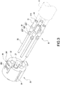
FIG. 3 is an exploded view of the plastic core and the conductive terminals of the invention; -
FIG. 4 is an exploded view of the easily assembled connector of the invention; -
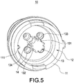
FIG. 5 is a perspective view of the insulative base of the invention; -
FIG. 6 is a cross-section view of the easily assembled connector of the invention; -
FIG. 7 is a cross-section view along line 7-7 inFIG. 6 ; -
FIG. 8 is a cross-section view along line 8-8 inFIG. 6 ; -
FIG. 9 is another exploded view of the invention; -
FIG. 10 is an exploded view of the easily assembled connector of the invention and a corresponding connector; -
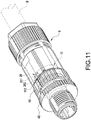
FIG. 11 is an assembled view of the easily assembled connector of the invention and a corresponding connector; and -
FIG. 12 is an assembled cross-section view of the easily assembled connector of the invention and a corresponding connector. - Please refer to
FIGS. 1-8 . The invention provides an easily assembled connector including aninsulative base 10, aplastic core 20 andconductive terminals 30. - Please refer to
FIGS. 4-5 first. Theinsulative base 10 is made of plastic and is substantially of a cylindrical shape. A side of theinsulative base 10 is formed with anannular wall 11. Achamber 12 is formed in theannular wall 11. The center of thechamber 12 is extended with a guidingpillar 13. Apositioning rib 111 is formed on an inner side of theannular wall 11. Two corresponding positions of theannular wall 11 are provided with anengaging hole 112 and anengaging notch 113. - The guiding
pillar 13 is substantially of a cross shape and includes avertical rod 131 and ahorizontal rod 132 across thevertical rod 131. Each end surface of both thevertical rod 132 and thehorizontal rod 132 is formed with agroove 133. A concavecurved surface 134 is formed between every two adjacent end surfaces of thevertical rod 132 and thehorizontal rod 132. Each concavecurved surface 134 has a step. A throughhole 14 penetrating theinsulative base 10 is provided at a root of each concavecurved surface 134. - Please refer to
FIGS. 1-3 . Theplastic core 20 is made of plastic and is a hollow cylinder installed in thechamber 12. The center of theplastic core 20 has a guidinghole 21.Troughs 22 are formed around the guidinghole 21 and communicate with the guidinghole 21. The guidinghole 21 is inserted by the guidingpillar 13. A terminal hole A is formed by eachtrough 22 and one of the concavecurved surface 134 as shown inFIG. 7 . - Furthermore, a
protrusion bar 23 is formed between every twoadjacent troughs 22. Eachprotrusion bar 23 is embedded into one of thegrooves 133. Ablocking ring 24 is provided in each of thetroughs 22. A bottom end of the blockingring 24 is formed with anelastic hook 241. An escapingspace 242 is formed between the back of theelastic hook 241 and the inner wall of thechamber 12 as shown inFIG. 6 . An outer surface of theplastic core 20 is formed with apositioning channel 25 for being embedded by thepositioning rib 111. Each of two corresponding positions of the front side of theplastic core 20 is provided with aflexible arm 26. An end of eachflexible arm 26 is formed with ahandle stem 261 being embedded into the engagingnotch 113 for engagement. A middle of eachflexible arm 26 is formed with anengaging block 262 being embedded into the engaginghole 112 for engagement. - Please refer to
FIGS. 4 ,6 and8 . Eachconductive terminal 30 is received in one of the terminal holes A. The embodiment uses male terminals as an example but female terminals are also available. Eachconductive terminal 30 includes a connectingsection 31, a fixingsection 32 extending from the connectingsection 31 and a guidingsection 33 extending from the fixingsection 32. - Further, each connecting
section 31 has awire hole 311 for being inserted by a core wire B1. Each fixingsection 32 has a stoppingring 321, aneck portion 322 below the stoppingring 321 and ahook portion 323 below theneck portion 322. - When assembling, insert the guiding
pillar 13 into the guidinghole 21 to form slidable connection first, and then insert each of theconductive terminals 30 into one of the terminal holes A. When thehook portion 323 reaches theelastic hook 241, theelastic hook 241 is pushed by thehook portion 323 to be aslant bent toward the escapingspace 242 to make theconductive terminals 30 easily enter the terminal holes A. After theelastic hook 241 has passed thehook portion 323, theelastic hook 241 will directly restore to be embedded into and engage with theneck portion 322. Also, the stoppingring 321 is stopped by the blockingring 24 and theelastic hook 241 is limited by thehook portion 323, so that theconductive terminals 30 can be prevented from being reversely pulled out of the terminal holes A. - The easily assembled connector of the invention further includes a
sleeve 40 around a side of theinsulative base 10 and a screwingelement 50 connected to an end of thesleeve 40 and put around theinsulative base 10. - Please refer to
FIG. 9 . In addition to the above embodiment, the easily assembled connector of the invention may also be assembled by inserting theconductive terminals 30 correspondingly into thetroughs 22 of theplastic core 20 first and then putting both theplastic core 20 and theconductive terminals 30 on the guidingpillar 13 through the guidinghole 21 to make slidable connection to accomplish rapid assembling of theplastic core 20, theconductive terminals 30 and theinsulative base 10. - Please refer to
FIGS. 10-12 . The easily assembled connector of the invention may be associated with a wire B and a connectingmember 9 to constitute a connector assembly. The connectingmember 9 is put around the wire B first, then connect each of the core wires B1 of the wire B to one of the connectingsections 31 of theconductive terminals 30, next insert the assembledconductive terminals 30 and core wires B1 into thetroughs 22 one by one, and finally put both theplastic core 20 and theconductive terminals 30 into thechamber 12 of theinsulative base 10. The assembling is accomplished by the slidable fit of the guidingpillar 13 and the guidinghole 21 and the positioning of theengaging block 262 of theflexible arm 26 and theengaging hole 112. When disassembling, press thehandle stem 261 to make theengaging block 262 escape from the engaginghole 112 and make theelastic hook 241 aslant bent outward by pulling to easily take both theplastic core 20 and theconductive terminals 30 out of theinsulative base 10. Also, all components can be used repeatedly.
Claims (11)
- An easily assembled connector comprising:an insulative base (10) having a chamber (12);a plastic core (20), correspondingly received in the chamber (12), having a guiding hole (21) and troughs (22) surrounding and communicating with the guiding hole (21), and each trough (22) being formed with a terminal hole (A); andconductive terminals (30) separately correspondingly installed in the terminal holes (A).
- The easily assembled connector of claim 1, wherein a center of the chamber (12) is extended with a guiding pillar (13), the guiding hole (21) is inserted by the guiding pillar (13), and the terminal hole (A) is formed by the trough (22) and the guiding pillar (13).
- The easily assembled connector of claim 2, wherein the guiding pillar (13) comprises a vertical rod (131) and a horizontal rod (132) across the vertical rod (131), a concave curved surface (134) is formed between every two adjacent end surfaces of the vertical rod (132) and the horizontal rod (132), and each terminal hole (A) is formed by one of the concave curved surfaces (134) and one of the troughs (22).
- The easily assembled connector of claim 3, wherein each end surface of both the vertical rod (132) and the horizontal rod (132) is formed with a groove (133), a protrusion bar (23) is formed between every two adjacent troughs (22), and each protrusion bar (23) is embedded into one of the grooves (133).
- The easily assembled connector of claim 3, wherein a through hole (14) penetrating the insulative base (10) is provided at a root of each concave curved surface (134), each conductive terminal (30) comprises a guiding section (33) penetrating through and projecting from the through hole (14).
- The easily assembled connector of claim 1, wherein a side of the insulative base (10) is formed with an annular wall (11), the chamber (12) is formed in the annular wall (11), a positioning rib (111) is formed on an inner side of the annular wall (11), and an outer surface of the plastic core (20) is formed with a positioning channel (25) for being embedded by the positioning rib (111).
- The easily assembled connector of claim 6, wherein two corresponding positions of the annular wall (11) are separately provided with an engaging hole (112) and an engaging notch (113), each of two corresponding positions of the plastic core (20) is provided with a flexible arm (26), each flexible arm (26) is formed with a handle stem (261) being embedded into the engaging notch (113) for engagement, and an engaging block (262) is embedded into the engaging hole (112) for engagement.
- The easily assembled connector of claim 1, wherein each conductive terminal (30) comprises a connecting section (31), a fixing section (32) extending from the connecting section (31) and a guiding section (33) extending from the fixing section (32), each fixing section (32) has a stopping ring (321), a blocking ring (24) is provided in each of the troughs (22), and the stopping ring (321) is stopped by the blocking ring (24).
- The easily assembled connector of claim 8, wherein the fixing section (32) has a neck portion (322) below the stopping ring (321), a bottom end of the blocking ring (24) is formed with an elastic hook (241), an escaping space (242) is formed between a back of the elastic hook (241) and an inner wall of the chamber 12, and the elastic hook (241) is embedded into and engage with the neck portion (322).
- The easily assembled connector of claim 8, wherein the connecting section (31) has a wire hole (311) for being inserted by a core wire (B1) of a wire (B).
- The easily assembled connector of claim 1, further comprising a sleeve (40) around a side of the insulative base (10) and a screwing element (50) connected to an end of the sleeve (40) and put around the insulative base (10).
Applications Claiming Priority (1)
| Application Number | Priority Date | Filing Date | Title |
|---|---|---|---|
| CN201910783325.4A CN112421283B (en) | 2019-08-23 | 2019-08-23 | Easy-to-assemble connector |
Publications (3)
| Publication Number | Publication Date |
|---|---|
| EP3783746A1 true EP3783746A1 (en) | 2021-02-24 |
| EP3783746A9 EP3783746A9 (en) | 2021-06-16 |
| EP3783746B1 EP3783746B1 (en) | 2026-03-04 |
Family
ID=68501521
Family Applications (1)
| Application Number | Title | Priority Date | Filing Date |
|---|---|---|---|
| EP19208142.0A Active EP3783746B1 (en) | 2019-08-23 | 2019-11-08 | Easily assembled connector |
Country Status (4)
| Country | Link |
|---|---|
| US (1) | US11128081B2 (en) |
| EP (1) | EP3783746B1 (en) |
| CN (1) | CN112421283B (en) |
| TW (1) | TWI703775B (en) |
Families Citing this family (2)
| Publication number | Priority date | Publication date | Assignee | Title |
|---|---|---|---|---|
| DE102019113494A1 (en) * | 2019-05-21 | 2020-11-26 | Harting Electric Gmbh & Co. Kg | Contact carrier |
| DE102020125345A1 (en) | 2020-09-29 | 2022-03-31 | Amphenol-Tuchel Electronics Gesellschaft mit beschränkter Haftung | contact carrier |
Citations (3)
| Publication number | Priority date | Publication date | Assignee | Title |
|---|---|---|---|---|
| US7351117B1 (en) * | 2006-11-06 | 2008-04-01 | Tyco Electronics Corporation | Electrical connector assembly having pre-staging and final staging contact configurations |
| US7494377B2 (en) * | 2004-08-13 | 2009-02-24 | Tyco Electronics Corporation | Electrical connector |
| US9954305B2 (en) * | 2014-08-12 | 2018-04-24 | Tyco Electronics (Shanghai) Co. Ltd. | Electric connector |
Family Cites Families (12)
| Publication number | Priority date | Publication date | Assignee | Title |
|---|---|---|---|---|
| EP0378845B1 (en) * | 1988-12-28 | 1994-11-30 | The Whitaker Corporation | Electrical connector housing assembly |
| US5496194A (en) * | 1993-10-04 | 1996-03-05 | The Whitaker Corporation | Electrical connector with two stage latch having improved retaining means |
| US6764350B2 (en) * | 2002-04-23 | 2004-07-20 | Itt Manufacturing Enterprises, Inc. | Connector contact retention |
| US7874860B2 (en) * | 2002-07-19 | 2011-01-25 | Phoenix Contact Gmbh & Co. Kg | Electrical connector |
| US7101192B1 (en) * | 2005-06-06 | 2006-09-05 | Amphenol Corporation | Secondary locking device for a multi-pin connector |
| DE102006048014A1 (en) * | 2006-10-09 | 2008-04-10 | Neutrik Aktiengesellschaft | XLR cable connector |
| CN201699217U (en) * | 2010-06-02 | 2011-01-05 | 亮泰企业股份有限公司 | Connector easy to disassemble and assemble conductive terminal |
| US8851933B2 (en) * | 2013-03-11 | 2014-10-07 | Kerdea Technologies, Inc. | Releasable electrical connection |
| CN207338812U (en) * | 2017-07-03 | 2018-05-08 | 凡甲电子(苏州)有限公司 | Electric connector and the electric connector combination with the electric connector |
| TWI660548B (en) * | 2018-06-15 | 2019-05-21 | 大陸商昆山安費諾正日電子有限公司 | Coupling structure of cable connector |
| TWM581780U (en) * | 2019-05-23 | 2019-08-01 | 大陸商昆山安費諾正日電子有限公司 | Cable connection device with unlocking sliding-sleeve |
| CN210156599U (en) * | 2019-08-23 | 2020-03-17 | 昆山安费诺正日电子有限公司 | Connector easy to assemble |
-
2019
- 2019-08-23 CN CN201910783325.4A patent/CN112421283B/en active Active
- 2019-08-28 TW TW108130884A patent/TWI703775B/en not_active IP Right Cessation
- 2019-10-16 US US16/655,197 patent/US11128081B2/en active Active
- 2019-11-08 EP EP19208142.0A patent/EP3783746B1/en active Active
Patent Citations (3)
| Publication number | Priority date | Publication date | Assignee | Title |
|---|---|---|---|---|
| US7494377B2 (en) * | 2004-08-13 | 2009-02-24 | Tyco Electronics Corporation | Electrical connector |
| US7351117B1 (en) * | 2006-11-06 | 2008-04-01 | Tyco Electronics Corporation | Electrical connector assembly having pre-staging and final staging contact configurations |
| US9954305B2 (en) * | 2014-08-12 | 2018-04-24 | Tyco Electronics (Shanghai) Co. Ltd. | Electric connector |
Also Published As
| Publication number | Publication date |
|---|---|
| TWI703775B (en) | 2020-09-01 |
| US11128081B2 (en) | 2021-09-21 |
| US20210057841A1 (en) | 2021-02-25 |
| TW202109997A (en) | 2021-03-01 |
| CN112421283B (en) | 2025-05-27 |
| EP3783746B1 (en) | 2026-03-04 |
| EP3783746A9 (en) | 2021-06-16 |
| CN112421283A (en) | 2021-02-26 |
Similar Documents
| Publication | Publication Date | Title |
|---|---|---|
| US7651375B2 (en) | Cable assembly having outer cover robustly supported | |
| US2025189A (en) | Plug cap | |
| EP2985840B1 (en) | Electric connector | |
| US2316267A (en) | Sleeve connector | |
| US10128613B2 (en) | Pin connector assembly | |
| CN103733446B (en) | For the contact element of plug-in electric connector | |
| US5413509A (en) | Multi-wire locking system | |
| US11128081B2 (en) | Easily assembled connector | |
| CN110350345A (en) | A kind of high current connector component | |
| KR101680273B1 (en) | Plug terminal for connector | |
| US7357661B2 (en) | Pressure coupling connector | |
| US6705574B2 (en) | Cable mounting structure | |
| KR20080003291U (en) | Female electrical terminal | |
| WO2020057629A1 (en) | Processing methods for conversion plug and power adapter, conversion plug, and power adapter | |
| US20170125945A1 (en) | Pin connector | |
| CN210156599U (en) | Connector easy to assemble | |
| CN107645079B (en) | Anti-loosening lamp connector | |
| US2319122A (en) | Electrical connection means | |
| TW200505116A (en) | Cable connector assembly and method for making the same | |
| KR101286898B1 (en) | Bnc connector with good stability of signal transmission | |
| US10153594B2 (en) | Electrical connector having elongated housing and interconnected upper and lower shells attached to the housing | |
| TWI393301B (en) | Power connector | |
| KR200420046Y1 (en) | Joint connector | |
| KR101651398B1 (en) | Coixial connecter of radio frequency | |
| CN210326446U (en) | Female end assembly structure of anti-overflow tin connector |
Legal Events
| Date | Code | Title | Description |
|---|---|---|---|
| PUAI | Public reference made under article 153(3) epc to a published international application that has entered the european phase |
Free format text: ORIGINAL CODE: 0009012 |
|
| STAA | Information on the status of an ep patent application or granted ep patent |
Free format text: STATUS: THE APPLICATION HAS BEEN PUBLISHED |
|
| AK | Designated contracting states |
Kind code of ref document: A1 Designated state(s): AL AT BE BG CH CY CZ DE DK EE ES FI FR GB GR HR HU IE IS IT LI LT LU LV MC MK MT NL NO PL PT RO RS SE SI SK SM TR |
|
| AX | Request for extension of the european patent |
Extension state: BA ME |
|
| STAA | Information on the status of an ep patent application or granted ep patent |
Free format text: STATUS: REQUEST FOR EXAMINATION WAS MADE |
|
| 17P | Request for examination filed |
Effective date: 20210824 |
|
| RBV | Designated contracting states (corrected) |
Designated state(s): AL AT BE BG CH CY CZ DE DK EE ES FI FR GB GR HR HU IE IS IT LI LT LU LV MC MK MT NL NO PL PT RO RS SE SI SK SM TR |
|
| STAA | Information on the status of an ep patent application or granted ep patent |
Free format text: STATUS: EXAMINATION IS IN PROGRESS |
|
| 17Q | First examination report despatched |
Effective date: 20230306 |
|
| GRAP | Despatch of communication of intention to grant a patent |
Free format text: ORIGINAL CODE: EPIDOSNIGR1 |
|
| STAA | Information on the status of an ep patent application or granted ep patent |
Free format text: STATUS: GRANT OF PATENT IS INTENDED |
|
| RIC1 | Information provided on ipc code assigned before grant |
Ipc: H01R 13/436 20060101AFI20251001BHEP Ipc: H01R 13/506 20060101ALI20251001BHEP Ipc: H01R 24/86 20110101ALN20251001BHEP Ipc: H01R 107/00 20060101ALN20251001BHEP |
|
| INTG | Intention to grant announced |
Effective date: 20251008 |
|
| GRAS | Grant fee paid |
Free format text: ORIGINAL CODE: EPIDOSNIGR3 |
|
| GRAA | (expected) grant |
Free format text: ORIGINAL CODE: 0009210 |
|
| STAA | Information on the status of an ep patent application or granted ep patent |
Free format text: STATUS: THE PATENT HAS BEEN GRANTED |
|
| P01 | Opt-out of the competence of the unified patent court (upc) registered |
Free format text: CASE NUMBER: UPC_APP_0000310_3783746/2026 Effective date: 20260106 |
|
| AK | Designated contracting states |
Kind code of ref document: B1 Designated state(s): AL AT BE BG CH CY CZ DE DK EE ES FI FR GB GR HR HU IE IS IT LI LT LU LV MC MK MT NL NO PL PT RO RS SE SI SK SM TR |
|
| REG | Reference to a national code |
Ref country code: CH Ref legal event code: F10 Free format text: ST27 STATUS EVENT CODE: U-0-0-F10-F00 (AS PROVIDED BY THE NATIONAL OFFICE) Effective date: 20260304 Ref country code: GB Ref legal event code: FG4D |
|
| REG | Reference to a national code |
Ref country code: IE Ref legal event code: FG4D |
|
| REG | Reference to a national code |
Ref country code: DE Ref legal event code: R096 Ref document number: 602019082014 Country of ref document: DE |