EP3783686A1 - Battery module - Google Patents
Battery module Download PDFInfo
- Publication number
- EP3783686A1 EP3783686A1 EP19769703.0A EP19769703A EP3783686A1 EP 3783686 A1 EP3783686 A1 EP 3783686A1 EP 19769703 A EP19769703 A EP 19769703A EP 3783686 A1 EP3783686 A1 EP 3783686A1
- Authority
- EP
- European Patent Office
- Prior art keywords
- battery module
- lower case
- heat conducting
- conducting plate
- boss
- Prior art date
- Legal status (The legal status is an assumption and is not a legal conclusion. Google has not performed a legal analysis and makes no representation as to the accuracy of the status listed.)
- Granted
Links
Images




Classifications
-
- H—ELECTRICITY
- H01—ELECTRIC ELEMENTS
- H01M—PROCESSES OR MEANS, e.g. BATTERIES, FOR THE DIRECT CONVERSION OF CHEMICAL ENERGY INTO ELECTRICAL ENERGY
- H01M10/00—Secondary cells; Manufacture thereof
- H01M10/60—Heating or cooling; Temperature control
- H01M10/65—Means for temperature control structurally associated with the cells
- H01M10/655—Solid structures for heat exchange or heat conduction
- H01M10/6554—Rods or plates
-
- H—ELECTRICITY
- H01—ELECTRIC ELEMENTS
- H01M—PROCESSES OR MEANS, e.g. BATTERIES, FOR THE DIRECT CONVERSION OF CHEMICAL ENERGY INTO ELECTRICAL ENERGY
- H01M10/00—Secondary cells; Manufacture thereof
- H01M10/60—Heating or cooling; Temperature control
- H01M10/61—Types of temperature control
- H01M10/613—Cooling or keeping cold
-
- H—ELECTRICITY
- H01—ELECTRIC ELEMENTS
- H01M—PROCESSES OR MEANS, e.g. BATTERIES, FOR THE DIRECT CONVERSION OF CHEMICAL ENERGY INTO ELECTRICAL ENERGY
- H01M10/00—Secondary cells; Manufacture thereof
- H01M10/60—Heating or cooling; Temperature control
- H01M10/65—Means for temperature control structurally associated with the cells
- H01M10/653—Means for temperature control structurally associated with the cells characterised by electrically insulating or thermally conductive materials
-
- H—ELECTRICITY
- H01—ELECTRIC ELEMENTS
- H01M—PROCESSES OR MEANS, e.g. BATTERIES, FOR THE DIRECT CONVERSION OF CHEMICAL ENERGY INTO ELECTRICAL ENERGY
- H01M50/00—Constructional details or processes of manufacture of the non-active parts of electrochemical cells other than fuel cells, e.g. hybrid cells
- H01M50/20—Mountings; Secondary casings or frames; Racks, modules or packs; Suspension devices; Shock absorbers; Transport or carrying devices; Holders
- H01M50/204—Racks, modules or packs for multiple batteries or multiple cells
- H01M50/207—Racks, modules or packs for multiple batteries or multiple cells characterised by their shape
- H01M50/209—Racks, modules or packs for multiple batteries or multiple cells characterised by their shape adapted for prismatic or rectangular cells
-
- H—ELECTRICITY
- H01—ELECTRIC ELEMENTS
- H01M—PROCESSES OR MEANS, e.g. BATTERIES, FOR THE DIRECT CONVERSION OF CHEMICAL ENERGY INTO ELECTRICAL ENERGY
- H01M50/00—Constructional details or processes of manufacture of the non-active parts of electrochemical cells other than fuel cells, e.g. hybrid cells
- H01M50/20—Mountings; Secondary casings or frames; Racks, modules or packs; Suspension devices; Shock absorbers; Transport or carrying devices; Holders
- H01M50/271—Lids or covers for the racks or secondary casings
-
- Y—GENERAL TAGGING OF NEW TECHNOLOGICAL DEVELOPMENTS; GENERAL TAGGING OF CROSS-SECTIONAL TECHNOLOGIES SPANNING OVER SEVERAL SECTIONS OF THE IPC; TECHNICAL SUBJECTS COVERED BY FORMER USPC CROSS-REFERENCE ART COLLECTIONS [XRACs] AND DIGESTS
- Y02—TECHNOLOGIES OR APPLICATIONS FOR MITIGATION OR ADAPTATION AGAINST CLIMATE CHANGE
- Y02E—REDUCTION OF GREENHOUSE GAS [GHG] EMISSIONS, RELATED TO ENERGY GENERATION, TRANSMISSION OR DISTRIBUTION
- Y02E60/00—Enabling technologies; Technologies with a potential or indirect contribution to GHG emissions mitigation
- Y02E60/10—Energy storage using batteries
Definitions
- the present disclosure relates to the field of energy storage devices, and particularly, to a battery module.
- a battery module is generally used as an energy storage system of a new energy vehicle, and the existing battery module includes a metal lower case.
- the metal lower case may generate spatter when being welded with other components such as an upper cover, and thus can lead to functional failures of other components.
- the metal lower case has a great weight and a lot of parts thereof are required to be electrically insulated. Once the insulation function of some parts fails, the quality of the battery module may be problematic.
- a heat conducting plate is usually provided to dissipate heat from the battery module.
- the lower case is welded to the heat conducting plate, the above-mentioned spattering problem also exists. Therefore, it is urgent to find a solution how to form a stable connection between the lower case and the heat conducting plate.
- the present disclosure provides a battery module, aiming to solve the problems in the related art and achieve a stable connection between the lower case and the heat conducing plate.
- the present disclosure provides a battery module, including a lower case, a plurality of battery cells sequentially stacked and received in the lower case; and a heat conducting plate; wherein a boss is formed on the lower case; the heat conducting plate is provided with a receiving hole; and the boss fits in the receiving hole, and a part or an entirety of the boss is fixed in the receiving hole.
- the lower case is made of an insulating material.
- the heat conducting plate is made of metal.
- the receiving hole is a circular hole; the boss forms a connecting portion and a limiting portion; and the connecting portion is located in the receiving hole, and the limiting portion limits the heat conducting plate.
- the receiving hole is a tapered hole; a surface of the boss facing away from the plurality of battery cells is flush with a surface of the heat conducting plate facing away from the plurality of battery cells.
- a plurality of receiving holes is provided, and the plurality of the receiving holes is arranged at an edge portion of the heat conducting plate along a length direction of the battery module; and/or the plurality of the receiving holes is arranged at the edge portion of the heat conducting plate along a width direction of the battery module.
- the lower case comprises two side plates and two end plates, and the two end plates are respectively fixedly connected to the two side plates; a plurality of bosses corresponding to the plurality of receiving holes is arranged at bottoms of the two side plates along the length direction of the battery module; and/or the plurality of bosses is arranged at the bottoms of the two end plates along the width direction of the battery module.
- each of the two side plates comprises a first plate and a second plate which are connected in an L shape; the first plate extends along a height direction of the battery module; the second plate extends along the width direction of the battery module; and the plurality of bosses is disposed on the second plate.
- the lower case is provided therein with a heat conducting structural adhesive fixed at the lower case.
- the battery module further includes an upper cover, and the upper cover and the lower case define a receiving cavity for receiving the plurality of the battery cells.
- the battery module provided by the present disclosure includes a lower case, a plurality of battery cells sequentially stacked and received in the lower case; and a heat conducting plate.
- a boss is formed on the lower case.
- the heat conducting plate is provided with a receiving hole. The boss fits in the receiving hole, and the boss is hot-melted and fixed in the receiving hole. Through the fitting of the boss and the receiving hole and the subsequent hot-melting, the hot-melted boss forms a fixed connection with the receiving hole, which solves the spattering problem caused by welding in the related art and improves the connection strength between the lower case and the heat conducting plate.
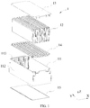
- FIG. 1 is an exploded view of a battery module provided in a first embodiment of the present disclosure.
- the embodiment of the present disclosure provides a battery module 1.
- the battery module 1 includes a lower case 11, a plurality of battery cells 12 sequentially stacked and received in the lower case 11, and an upper cover 13.
- the upper cover 13 and the lower case 11 together form a receiving cavity for receiving the plurality of battery cells 12.
- the battery module 1 further includes a heat conducting plate 15 for heat dissipation.
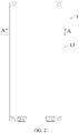
- FIG. 2 is a top view of a battery module provided in a first embodiment of the present disclosure
- FIG. 3 is a cross-sectional view taken along line A-A in FIG. 2
- FIG. 4 is an enlarged view of a portion B in FIG. 3 .
- a boss 111 is formed on the lower case 11, and the heat conducting plate 15 is provided with a receiving hole 151.
- the boss 111 fits in the receiving hole 151.
- a part or an entirety of the boss 111 is fixed in the receiving hole 151.
- the battery module provided by the embodiment of the present disclosure is provided with the receiving hole 151 on the heat conducting plate 15 and a boss 111 is formed on the lower case 11, so that compared with the case in which the heat conducting plate 15 is injection-molded on the lower case 11 as a whole, the heat conducting plate 15 is only locally heated instead of being heated for the entire large area.
- the lower case 11 and the heat conducting plate 15 adopt a split structure as described above, and thus the lower case 11 and the heat conducting plate 15 can be made of different materials.
- the lower case 11 can be made of an insulating material, so as to solve the problem of metal spattering during the welding process of the metal lower case in the related art while reducing the weight of the battery module 1.
- the heat conducting plate 15 can be made of a material having a good thermal conductivity, such as using a metal heat conducting plate 15 to dissipate the heat of the battery cells 12, thereby improving the heat dissipation effect.
- the lower case 11 made of the insulating material can solve problems such as a lots of parts of the metal lower case are required to be insulated and insulations are often ineffective.
- the boss 111 may be formed in the injection molding process of the lower case 11, and the receiving hole 151 can be formed on the heat conducting plate 15 by mechanical processing.
- the molding processes of the boss 111 and the receiving hole 151 are both very simple, and it is also easy to implement the hot-melting process of the boss 111 and the receiving hole 151.
- the battery module 1 may include two side plates 112 and two end plates 113.
- the side plates 112 and the end plates 113 fix the battery cells 12 to restrict the expansion of the battery cells 12.
- the heat conducting plate 15 can be connected to ends of the side plates 112 and the end plates 113 facing away from the upper cover 13, i.e., being connected to bottoms of the side plates 112 and/or the end plates 113.
- the heat can be dissipated through the heat conducting plate 15.
- the side plate 112 may include a first plate 111a, and the above boss 111 is disposed on the first plate 111a. It is also possible that as shown in FIG. 4 , the side plate 112 includes a first plate 111a and a second plate 111b which are connected in an L shape. The first plate 111a extends in a height direction (Z direction in FIG. 1 ) of the battery module 1, and the second plate 111b extends in a width direction (X direction) of the battery module 1.
- the above boss 111 is provided on the second plate 111b.
- the boss 111 and the side plate 112 can be formed into one piece by injection molding. In other embodiments, the boss 111 can also be disposed on the end plate 113 and formed into one piece with the end plate 113 by injection molding.
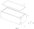
- FIG. 5 is a schematic exploded view showing a structure of the battery module provided in the first embodiment of the present disclosure, in which the lower case and the heat conducting plate are to be fitted with each other
- FIG. 6 is an enlarged view of a portion C in FIG. 5 .
- the receiving hole 151 is a circular hole, and the boss 111 is cylindrical before hot-melting, as shown in FIG. 6 .
- the hot-melted boss 111 forms a connecting portion 111a and a limiting portion 111b.
- the connecting portion 111a is located in the receiving hole 151, and the limiting portion 111b limits the heat conducting plate 15.
- the above structure can achieve a quick assembly of the heat conducting plate 15, and the limitation effect of the limiting portion 111b prevents the heat conducting plate 15 from escaping, thereby improving the reliability of the connection between the heat conducting plate 15 and the lower case 11.
- the above receiving hole 151 and the boss 111 can have other shapes, as long as they can satisfy that the boss 111 is hot-melted after passing through the receiving hole 151.
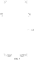
- FIG. 7 is a top view of a battery module provided in a second embodiment of the present disclosure
- FIG. 8 is a cross-sectional view taken along line E-E in FIG. 7
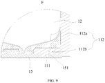
- FIG. 9 is an enlarged view of a portion F in FIG. 8 .
- the receiving hole 151 is a tapered hole, i.e., an aperture of the receiving hole 151 on a side facing away from the battery cell 12 is larger than its aperture on a side close to the battery cell 12.
- the boss 111 has a cylindrical shape before hot-melting, and a surface of the hot-melted boss 111 facing away from the battery cell 12 is flush with a surface of the heat conducting plate 15 facing away from the battery cell 12.
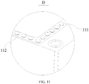
- FIG. 10 is a schematic exploded view showing a structure of the battery module provided in the second embodiment of the present disclosure, in which the lower case and the heat conducting plate are to be fitted with each other; and FIG. 11 is an enlarged view of a portion D in FIG. 10 .
- FIG. 11 shows a state of the hot-melted boss 111.
- the boss 111 is completely filled in the receiving hole 151 to form a shape similar to a "nail cap".
- a surface of the hot-melted boss 111 facing away from the battery cell 12 is flush with a surface of the heat conducting plate 15 facing away from the battery cell 12, such that the occupied space of the battery module 1 is reduced and the space utilization rate is high, thereby enhancing the energy density of the battery module 1.
- the lower case 11 can be made of a polymer material having an insulating property, and is formed by a molding method such as injection molding, extrusion or mold pressing. In this way, the spattering during welding of the metal lower case in the related art and the failures of other components can be avoided, and thus the quality of the battery module 1 is improved.
- the battery cell 12 can have a square or cylindrical shape, which is not limited herein.
- the upper cover 13 can be made of a polymer material having an insulating property, and is formed by molding method such as injection molding, extrusion or mold pressing.
- the heat conducting plate 15 is made of metal, which has a higher thermal conductivity than the lower case 11 and the upper cover 13.
- the heat conducting plate is made of metal such as copper or aluminum, which is not further limited herein.
- the heat conducting plate 15 is a rectangular plate. It can be understood that the heat conducting plate 15 can also have other shapes as long as it matches with the shape of the lower case 11.
- a plurality of receiving holes 151 can be provided.
- the plurality of receiving holes 151 are arranged at an edge portion of the heat conducting plate 15 along the length direction (direction Y) of the battery module 1.
- the receiving holes 151 can also be arranged at the edge portion of the heat conducting plate 15 along the width direction (X direction) of the battery module 1.
- the receiving holes 151 can also be arranged at the edge portion of the heat conducting plate 15 along both the width direction (X direction) and the length direction (Y direction) of the battery module 1.
- the receiving holes 151 are arranged at the edge portion of the heat conducting plate 15 along the length direction and the width direction of the battery module 1, such that more receiving holes 151 can be provided to fit with the bosses 111 on the lower case 11. In view of this, there are more connecting points and the connection strength is greater, and thus the overall structural strength of the battery module 1 is improved.
- positions of the bosses 111 correspond to those of the receiving holes 151, and can be arranged at the bottom of the side plate 112 along the length direction (Y direction) of the battery module 1, and can also be arranged at the bottom of the end plate 113 along the width direction (X direction) of the battery module 1.
- the boss 111 can also be provided at bottoms of both the side plate 112 and the end plate 113 both along the length direction (Y direction) of the battery module 1 and along the width direction (X direction) of the battery module 1.
- the lower case 11 is provided therein with a structural adhesive 14 fixed to the lower case 11, and the structural adhesive 14 can be a heat conducting structural adhesive.
- the structural adhesive 14 can be a heat conducting structural adhesive.
- the adhesive can be monitored in real time, so as to ensure a good application effect of the adhesive.
- the receiving hole 151 of the heat conducting plate 15 is fitted and hot-melted with the boss 111 of the lower case 11 to form a stable connection between the heat conducting plate 15 and the lower case 11.
- the process sequence of assembling the heat conducting plate 15 after applying the adhesive can also prevent the adhesive from overflowing from the lower case 11, and the heat conducting structural adhesive is conducive to the heat transfer, thereby further improving the heat dissipation effect of the battery module 1.
Landscapes
- Chemical & Material Sciences (AREA)
- Chemical Kinetics & Catalysis (AREA)
- Electrochemistry (AREA)
- General Chemical & Material Sciences (AREA)
- Engineering & Computer Science (AREA)
- Manufacturing & Machinery (AREA)
- Secondary Cells (AREA)
- Battery Mounting, Suspending (AREA)
Abstract
Description
- The present disclosure relates to the field of energy storage devices, and particularly, to a battery module.
- A battery module is generally used as an energy storage system of a new energy vehicle, and the existing battery module includes a metal lower case. The metal lower case may generate spatter when being welded with other components such as an upper cover, and thus can lead to functional failures of other components. In addition, the metal lower case has a great weight and a lot of parts thereof are required to be electrically insulated. Once the insulation function of some parts fails, the quality of the battery module may be problematic.
- A heat conducting plate is usually provided to dissipate heat from the battery module. When the lower case is welded to the heat conducting plate, the above-mentioned spattering problem also exists. Therefore, it is urgent to find a solution how to form a stable connection between the lower case and the heat conducting plate.
- The present disclosure provides a battery module, aiming to solve the problems in the related art and achieve a stable connection between the lower case and the heat conducing plate.
- The present disclosure provides a battery module, including a lower case, a plurality of battery cells sequentially stacked and received in the lower case; and a heat conducting plate;
wherein a boss is formed on the lower case;
the heat conducting plate is provided with a receiving hole; and
the boss fits in the receiving hole, and a part or an entirety of the boss is fixed in the receiving hole. - In an embodiment, the lower case is made of an insulating material.
- In an embodiment, the heat conducting plate is made of metal.
- In an embodiment, the receiving hole is a circular hole;
the boss forms a connecting portion and a limiting portion; and
the connecting portion is located in the receiving hole, and the limiting portion limits the heat conducting plate. - In an embodiment, the receiving hole is a tapered hole; a surface of the boss facing away from the plurality of battery cells is flush with a surface of the heat conducting plate facing away from the plurality of battery cells.
- In an embodiment, a plurality of receiving holes is provided, and the plurality of the receiving holes is arranged at an edge portion of the heat conducting plate along a length direction of the battery module; and/or the plurality of the receiving holes is arranged at the edge portion of the heat conducting plate along a width direction of the battery module.
- In an embodiment, the lower case comprises two side plates and two end plates, and the two end plates are respectively fixedly connected to the two side plates; a plurality of bosses corresponding to the plurality of receiving holes is arranged at bottoms of the two side plates along the length direction of the battery module; and/or the plurality of bosses is arranged at the bottoms of the two end plates along the width direction of the battery module.
- In an embodiment, each of the two side plates comprises a first plate and a second plate which are connected in an L shape;
the first plate extends along a height direction of the battery module;
the second plate extends along the width direction of the battery module; and
the plurality of bosses is disposed on the second plate. - In an embodiment, the lower case is provided therein with a heat conducting structural adhesive fixed at the lower case.
- In an embodiment, the battery module further includes an upper cover, and the upper cover and the lower case define a receiving cavity for receiving the plurality of the battery cells.
- The technical solutions provided by the present disclosure can achieve the following beneficial effects.
- The battery module provided by the present disclosure includes a lower case, a plurality of battery cells sequentially stacked and received in the lower case; and a heat conducting plate. A boss is formed on the lower case. The heat conducting plate is provided with a receiving hole. The boss fits in the receiving hole, and the boss is hot-melted and fixed in the receiving hole. Through the fitting of the boss and the receiving hole and the subsequent hot-melting, the hot-melted boss forms a fixed connection with the receiving hole, which solves the spattering problem caused by welding in the related art and improves the connection strength between the lower case and the heat conducting plate.
- It should be understood that the above general description and the following detailed description are merely illustrative and are not intended to limit the present disclosure.
- In order to more clearly illustrate the technical solutions of the present disclosure or in the related art, drawings used in the specific embodiments or the description of the related art will be briefly described below. The drawings introduced as below merely illustrate some embodiments of the present disclosure, and those skilled in the art can obtain other drawings based on these drawings without any creative efforts.
-
FIG. 1 is an exploded view of a battery module provided in an embodiment of the present disclosure; -
FIG. 2 is a top view of a battery module provided in a first embodiment of the present disclosure; -
FIG. 3 is a cross-sectional view taken along line A-A inFIG. 2 ; -
FIG. 4 is an enlarged view of a portion B inFIG. 3 ; -
FIG. 5 is a schematic exploded view showing a structure of the battery module provided in the first embodiment of the present disclosure, in which a lower case and a heat conducting plate are to be fitted with each other; -
FIG. 6 is an enlarged view of a portion C inFIG. 5 ; -
FIG. 7 is a top view of a battery module provided in a second embodiment of the present disclosure; -
FIG. 8 is a cross-sectional view taken along line E-E inFIG. 7 ; -
FIG. 9 is an enlarged view of a portion F inFIG. 8 ; -
FIG. 10 is a schematic exploded view showing a structure of the battery module provided in the second embodiment of the present disclosure, in which the lower case and the heat conducting plate are to be fitted with each other; and -
FIG. 11 is an enlarged view of a portion D inFIG. 10 . -
- 1
- battery module;
11 lower case;
111 boss;
111a connecting portion;
111b limiting portion;
112 side plate
112a first plate;
112b second plate;
113 end plate;
12 battery cell;
13 top cover;
14 structural adhesive;
15 heat conducting plate; and
151 receiving hole. - The drawings described herein, which illustrate the embodiments of the present disclosure, are incorporated in and constitute a part of the specification, and used to explain the principles of the present disclosure in combination with the specification.
- The technical solutions of the present disclosure will be clearly and thoroughly described as follow with reference to the accompanying drawings. It is obvious that the described embodiments are parts of the present disclosure, rather than all embodiments. Based on the embodiments of the present disclosure, all other embodiments obtained by those skilled in the art without paying any inventive efforts shall fall within the protection scope of the present disclosure.
-
FIG. 1 is an exploded view of a battery module provided in a first embodiment of the present disclosure. As shown inFIG. 1 , the embodiment of the present disclosure provides abattery module 1. Thebattery module 1 includes alower case 11, a plurality ofbattery cells 12 sequentially stacked and received in thelower case 11, and anupper cover 13. Theupper cover 13 and thelower case 11 together form a receiving cavity for receiving the plurality ofbattery cells 12. - An electrode assembly and electrolyte are disposed in the
battery cell 12, and the electrode assembly electrochemically reacts with the electrolyte to output electric energy. Since heat generated during the reaction should be dissipated in time, thebattery module 1 further includes aheat conducting plate 15 for heat dissipation. -
FIG. 2 is a top view of a battery module provided in a first embodiment of the present disclosure,FIG. 3 is a cross-sectional view taken along line A-A inFIG. 2 , andFIG. 4 is an enlarged view of a portion B inFIG. 3 . - A
boss 111 is formed on thelower case 11, and theheat conducting plate 15 is provided with a receivinghole 151. Theboss 111 fits in the receivinghole 151. A part or an entirety of theboss 111 is fixed in the receivinghole 151. Thus, the spattering problem caused by welding in the related art can be solved, and the connection strength between thelower case 11 and theheat conducting plate 15 can be increased. The battery module provided by the embodiment of the present disclosure is provided with the receivinghole 151 on theheat conducting plate 15 and aboss 111 is formed on thelower case 11, so that compared with the case in which theheat conducting plate 15 is injection-molded on thelower case 11 as a whole, theheat conducting plate 15 is only locally heated instead of being heated for the entire large area. Therefore, problems such as high temperature deterioration will not occur to theheat conducting plate 15, and a relatively large deformation, which will result in a decrease in flatness, will not occur. The reason for that is once the flatness of theheat conducting plate 15 is lowered, the contact effect between thebattery module 1 and the outside will be affected, thereby affecting the heat dissipation of thebattery module 1. - The
lower case 11 and theheat conducting plate 15 adopt a split structure as described above, and thus thelower case 11 and theheat conducting plate 15 can be made of different materials. For example, thelower case 11 can be made of an insulating material, so as to solve the problem of metal spattering during the welding process of the metal lower case in the related art while reducing the weight of thebattery module 1. Theheat conducting plate 15 can be made of a material having a good thermal conductivity, such as using a metalheat conducting plate 15 to dissipate the heat of thebattery cells 12, thereby improving the heat dissipation effect. In addition, thelower case 11 made of the insulating material can solve problems such as a lots of parts of the metal lower case are required to be insulated and insulations are often ineffective. - The
boss 111 may be formed in the injection molding process of thelower case 11, and the receivinghole 151 can be formed on theheat conducting plate 15 by mechanical processing. Thus, the molding processes of theboss 111 and the receivinghole 151 are both very simple, and it is also easy to implement the hot-melting process of theboss 111 and the receivinghole 151. - In an embodiment, the
battery module 1 may include twoside plates 112 and twoend plates 113. Theside plates 112 and theend plates 113 fix thebattery cells 12 to restrict the expansion of thebattery cells 12. Theheat conducting plate 15 can be connected to ends of theside plates 112 and theend plates 113 facing away from theupper cover 13, i.e., being connected to bottoms of theside plates 112 and/or theend plates 113. When the plurality ofbattery cells 12 is disposed in thelower case 11, the heat can be dissipated through theheat conducting plate 15. - The
side plate 112 may include afirst plate 111a, and theabove boss 111 is disposed on thefirst plate 111a. It is also possible that as shown inFIG. 4 , theside plate 112 includes afirst plate 111a and a second plate 111b which are connected in an L shape. Thefirst plate 111a extends in a height direction (Z direction inFIG. 1 ) of thebattery module 1, and the second plate 111b extends in a width direction (X direction) of thebattery module 1. Theabove boss 111 is provided on the second plate 111b. In an embodiment, theboss 111 and theside plate 112 can be formed into one piece by injection molding. In other embodiments, theboss 111 can also be disposed on theend plate 113 and formed into one piece with theend plate 113 by injection molding. -
FIG. 5 is a schematic exploded view showing a structure of the battery module provided in the first embodiment of the present disclosure, in which the lower case and the heat conducting plate are to be fitted with each other,FIG. 6 is an enlarged view of a portion C inFIG. 5 . - In the specific embodiment, the receiving
hole 151 is a circular hole, and theboss 111 is cylindrical before hot-melting, as shown inFIG. 6 . The hot-meltedboss 111 forms a connectingportion 111a and a limiting portion 111b. Referring toFIG. 4 , the connectingportion 111a is located in the receivinghole 151, and the limiting portion 111b limits theheat conducting plate 15. - The above structure can achieve a quick assembly of the
heat conducting plate 15, and the limitation effect of the limiting portion 111b prevents theheat conducting plate 15 from escaping, thereby improving the reliability of the connection between theheat conducting plate 15 and thelower case 11. - The
above receiving hole 151 and theboss 111 can have other shapes, as long as they can satisfy that theboss 111 is hot-melted after passing through the receivinghole 151. -
FIG. 7 is a top view of a battery module provided in a second embodiment of the present disclosure,FIG. 8 is a cross-sectional view taken along line E-E inFIG. 7 , andFIG. 9 is an enlarged view of a portion F inFIG. 8 . - In an implementation, as shown in
FIG. 7 to FIG. 9 , the receivinghole 151 is a tapered hole, i.e., an aperture of the receivinghole 151 on a side facing away from thebattery cell 12 is larger than its aperture on a side close to thebattery cell 12. Theboss 111 has a cylindrical shape before hot-melting, and a surface of the hot-meltedboss 111 facing away from thebattery cell 12 is flush with a surface of theheat conducting plate 15 facing away from thebattery cell 12. -
FIG. 10 is a schematic exploded view showing a structure of the battery module provided in the second embodiment of the present disclosure, in which the lower case and the heat conducting plate are to be fitted with each other; andFIG. 11 is an enlarged view of a portion D inFIG. 10 . - Referring to
FIGs. 9 and11, FIG. 11 shows a state of the hot-meltedboss 111. At this time, theboss 111 is completely filled in the receivinghole 151 to form a shape similar to a "nail cap". A surface of the hot-meltedboss 111 facing away from thebattery cell 12 is flush with a surface of theheat conducting plate 15 facing away from thebattery cell 12, such that the occupied space of thebattery module 1 is reduced and the space utilization rate is high, thereby enhancing the energy density of thebattery module 1. - As described above, the
lower case 11 can be made of a polymer material having an insulating property, and is formed by a molding method such as injection molding, extrusion or mold pressing. In this way, the spattering during welding of the metal lower case in the related art and the failures of other components can be avoided, and thus the quality of thebattery module 1 is improved. - The
battery cell 12 can have a square or cylindrical shape, which is not limited herein. - The
upper cover 13 can be made of a polymer material having an insulating property, and is formed by molding method such as injection molding, extrusion or mold pressing. - The
heat conducting plate 15 is made of metal, which has a higher thermal conductivity than thelower case 11 and theupper cover 13. For example, the heat conducting plate is made of metal such as copper or aluminum, which is not further limited herein. - Further, the
heat conducting plate 15 is a rectangular plate. It can be understood that theheat conducting plate 15 can also have other shapes as long as it matches with the shape of thelower case 11. - Further, a plurality of receiving
holes 151 can be provided. The plurality of receivingholes 151 are arranged at an edge portion of theheat conducting plate 15 along the length direction (direction Y) of thebattery module 1. The receiving holes 151 can also be arranged at the edge portion of theheat conducting plate 15 along the width direction (X direction) of thebattery module 1. The receiving holes 151 can also be arranged at the edge portion of theheat conducting plate 15 along both the width direction (X direction) and the length direction (Y direction) of thebattery module 1. In the embodiment, as an example, the receivingholes 151 are arranged at the edge portion of theheat conducting plate 15 along the length direction and the width direction of thebattery module 1, such that more receivingholes 151 can be provided to fit with thebosses 111 on thelower case 11. In view of this, there are more connecting points and the connection strength is greater, and thus the overall structural strength of thebattery module 1 is improved. - Correspondingly, positions of the
bosses 111 correspond to those of the receivingholes 151, and can be arranged at the bottom of theside plate 112 along the length direction (Y direction) of thebattery module 1, and can also be arranged at the bottom of theend plate 113 along the width direction (X direction) of thebattery module 1. Theboss 111 can also be provided at bottoms of both theside plate 112 and theend plate 113 both along the length direction (Y direction) of thebattery module 1 and along the width direction (X direction) of thebattery module 1. - In an embodiment, the
lower case 11 is provided therein with astructural adhesive 14 fixed to thelower case 11, and thestructural adhesive 14 can be a heat conducting structural adhesive. During the assembling of thebattery module 1, thelower case 11, thebattery cells 12 and theupper cover 13 are assembled first, and then the adhesive is applied. Thus, the application of the adhesive can be monitored in real time, so as to ensure a good application effect of the adhesive. After the adhesive is applied, the receivinghole 151 of theheat conducting plate 15 is fitted and hot-melted with theboss 111 of thelower case 11 to form a stable connection between theheat conducting plate 15 and thelower case 11. The process sequence of assembling theheat conducting plate 15 after applying the adhesive can also prevent the adhesive from overflowing from thelower case 11, and the heat conducting structural adhesive is conducive to the heat transfer, thereby further improving the heat dissipation effect of thebattery module 1. - The preferable embodiments of the present disclosure described above are not intended to limit the claims. Those skilled in the art can make various modifications and changes. Any modification, equivalent substitution and improvement made without departing from the concept of the present disclosure shall fall within the protection scope of the present disclosure.
Claims (10)
- A battery module, characterized in comprising:a lower case;a plurality of battery cells sequentially stacked and received in the lower case; anda heat conducting plate,wherein a boss is formed on the lower case;the heat conducting plate is provided with a receiving hole; andthe boss fits in the receiving hole, and a part or an entirety of the boss is fixed in the receiving hole.
- The battery module according to claim 1, characterized in that the lower case is made of an insulating material.
- The battery module according to claim 1, characterized in that the heat conducting plate is made of metal.
- The battery module according to claim 1, characterized in that the receiving hole is a circular hole, and the boss forms a connecting portion and a limiting portion;
the connecting portion is located in the receiving hole, and the limiting portion limits the heat conducting plate. - The battery module according to claim 1, characterized in that the receiving hole is a tapered hole; a surface of the boss facing away from the plurality of battery cells is flush with a surface of the heat conducting plate facing away from the plurality of battery cells.
- The battery module according to claim 1, characterized in that a plurality of receiving holes is provided, and the plurality of the receiving holes is arranged at an edge portion of the heat conducting plate along a length direction of the battery module; and/or the plurality of the receiving holes is arranged at the edge portion of the heat conducting plate along a width direction of the battery module.
- The battery module according to claim 6, characterized in that the lower case comprises two side plates and two end plates, and the two end plates are respectively fixedly connected to the two side plates; a plurality of bosses corresponding to the plurality of receiving holes is arranged at bottoms of the two side plates along the length direction of the battery module; and/or the plurality of bosses is arranged at the bottoms of the two end plates along the width direction of the battery module.
- The battery module according to claim 7, characterized in that each of the two side plates comprises a first plate and a second plate which are connected in an L shape;
the first plate extends along a height direction of the battery module;
the second plate extends along the width direction of the battery module; and
the plurality of bosses is disposed on the second plate. - The battery module according to claim 1, characterized in that the lower case is provided therein with a heat conducting structural adhesive fixed at the lower case.
- The battery module according to claim 1, characterized in further comprising an upper cover,
wherein the upper cover and the lower case define a receiving cavity for receiving the plurality of the battery cells.
Applications Claiming Priority (2)
| Application Number | Priority Date | Filing Date | Title |
|---|---|---|---|
| CN201920997463.8U CN209747611U (en) | 2019-06-28 | 2019-06-28 | Battery module |
| PCT/CN2019/095039 WO2020258369A1 (en) | 2019-06-28 | 2019-07-08 | Battery module |
Publications (3)
| Publication Number | Publication Date |
|---|---|
| EP3783686A4 EP3783686A4 (en) | 2021-02-24 |
| EP3783686A1 true EP3783686A1 (en) | 2021-02-24 |
| EP3783686B1 EP3783686B1 (en) | 2022-05-04 |
Family
ID=68724074
Family Applications (1)
| Application Number | Title | Priority Date | Filing Date |
|---|---|---|---|
| EP19769703.0A Active EP3783686B1 (en) | 2019-06-28 | 2019-07-08 | Battery module |
Country Status (4)
| Country | Link |
|---|---|
| US (1) | US20220123387A1 (en) |
| EP (1) | EP3783686B1 (en) |
| CN (1) | CN209747611U (en) |
| WO (1) | WO2020258369A1 (en) |
Cited By (1)
| Publication number | Priority date | Publication date | Assignee | Title |
|---|---|---|---|---|
| WO2023090983A1 (en) * | 2021-11-18 | 2023-05-25 | 주식회사 엘지에너지솔루션 | Battery module having improved airtightness and heat resistance of module case |
Families Citing this family (2)
| Publication number | Priority date | Publication date | Assignee | Title |
|---|---|---|---|---|
| CN113851769B (en) * | 2021-09-30 | 2025-12-19 | 厦门海辰储能科技股份有限公司 | Battery cell |
| CN217485653U (en) * | 2022-07-07 | 2022-09-23 | 宁德时代新能源科技股份有限公司 | Battery box and battery and electrical equipment having the same |
Family Cites Families (14)
| Publication number | Priority date | Publication date | Assignee | Title |
|---|---|---|---|---|
| US3304109A (en) * | 1965-04-21 | 1967-02-14 | Hi Shear Corp | Joint including tapered fastener |
| JP4379467B2 (en) * | 2006-12-11 | 2009-12-09 | 日産自動車株式会社 | Battery module |
| DE102010012993A1 (en) * | 2010-03-26 | 2011-09-29 | Daimler Ag | Battery for e.g. electrical vehicle, has set of single cells secured at heat guide plate by attachment members i.e. rivets, where attachment members and framework of single cells are formed as common mold part |
| JP5710375B2 (en) * | 2011-05-13 | 2015-04-30 | 日立オートモティブシステムズ株式会社 | Power storage device |
| US20130115496A1 (en) * | 2011-11-07 | 2013-05-09 | Johnson Controls Technology Llc | One-piece housing with plugs for prismatic cell assembly |
| DE102012018038A1 (en) * | 2012-09-13 | 2014-03-13 | Daimler Ag | Single cell and battery of a plurality of single cells |
| KR101941117B1 (en) * | 2015-02-27 | 2019-01-23 | 주식회사 엘지화학 | Battery module |
| DE102015010664A1 (en) * | 2015-08-14 | 2017-02-16 | Daimler Ag | battery |
| WO2017052296A1 (en) * | 2015-09-24 | 2017-03-30 | 주식회사 엘지화학 | Battery module |
| CN106229430A (en) * | 2015-12-02 | 2016-12-14 | 深圳市博亿能科技有限公司 | A kind of power battery box |
| US10601003B2 (en) * | 2017-10-30 | 2020-03-24 | Lg Chem, Ltd. | Battery module and method of assembling the battery module |
| KR102128588B1 (en) * | 2017-12-26 | 2020-07-08 | 에스케이이노베이션 주식회사 | Battery module and its manufacturing method |
| CN208173663U (en) * | 2018-05-11 | 2018-11-30 | 深圳市逸尘运动科技有限公司 | Lithium battery mould group |
| CN209747614U (en) * | 2019-06-28 | 2019-12-06 | 江苏时代新能源科技有限公司 | battery module |
-
2019
- 2019-06-28 CN CN201920997463.8U patent/CN209747611U/en active Active
- 2019-07-08 EP EP19769703.0A patent/EP3783686B1/en active Active
- 2019-07-08 US US16/498,208 patent/US20220123387A1/en not_active Abandoned
- 2019-07-08 WO PCT/CN2019/095039 patent/WO2020258369A1/en not_active Ceased
Cited By (3)
| Publication number | Priority date | Publication date | Assignee | Title |
|---|---|---|---|---|
| WO2023090983A1 (en) * | 2021-11-18 | 2023-05-25 | 주식회사 엘지에너지솔루션 | Battery module having improved airtightness and heat resistance of module case |
| KR20230073034A (en) * | 2021-11-18 | 2023-05-25 | 주식회사 엘지에너지솔루션 | Battery module with improved airtightness and heat resistance of the module case |
| JP2024500658A (en) * | 2021-11-18 | 2024-01-10 | エルジー エナジー ソリューション リミテッド | Battery module with improved airtightness and heat resistance of the module case |
Also Published As
| Publication number | Publication date |
|---|---|
| EP3783686A4 (en) | 2021-02-24 |
| WO2020258369A1 (en) | 2020-12-30 |
| EP3783686B1 (en) | 2022-05-04 |
| CN209747611U (en) | 2019-12-06 |
| US20220123387A1 (en) | 2022-04-21 |
Similar Documents
| Publication | Publication Date | Title |
|---|---|---|
| US11735783B2 (en) | Battery module | |
| US11502348B2 (en) | Battery module | |
| US8530078B2 (en) | Secondary battery | |
| US10115954B2 (en) | Battery module | |
| US8822061B2 (en) | Battery module with plurality of batteries having bent terminal portions connected with fixing plate | |
| US20130164585A1 (en) | Secondary battery | |
| KR20190064835A (en) | Battery pack | |
| KR102663725B1 (en) | Secondary battery | |
| EP3783686A1 (en) | Battery module | |
| KR20190002611A (en) | All solid-state cells | |
| WO2024250409A1 (en) | End cover assembly, battery cell, battery module, and energy storage device | |
| US20160233470A1 (en) | Battery pack having electric insulating pack case | |
| CN110048077B (en) | Electrode member, electrode assembly and rechargeable battery | |
| KR20040005243A (en) | Battery unit and the lithium secondary battery applying the same | |
| KR20230013599A (en) | Pouch type rechargeable-battery and method for manufacturing the same | |
| JP7115013B2 (en) | power storage device | |
| CN218334226U (en) | Single battery and battery pack | |
| KR102922134B1 (en) | Battery module and manufacturing method thereof | |
| CN222762801U (en) | Thermally Enhanced Capacitors | |
| CN221928809U (en) | Busbars and capacitors | |
| CN221530093U (en) | Cover plate assembly, battery and electric equipment | |
| KR100950035B1 (en) | Member for connecting battery cell and connecting member and method of manufacturing battery module using same | |
| CN209747615U (en) | battery module | |
| CN119009355A (en) | Spacer ring, power battery and battery module | |
| CN121529117A (en) | A battery module and electrical device |
Legal Events
| Date | Code | Title | Description |
|---|---|---|---|
| STAA | Information on the status of an ep patent application or granted ep patent |
Free format text: STATUS: UNKNOWN |
|
| STAA | Information on the status of an ep patent application or granted ep patent |
Free format text: STATUS: THE INTERNATIONAL PUBLICATION HAS BEEN MADE |
|
| PUAI | Public reference made under article 153(3) epc to a published international application that has entered the european phase |
Free format text: ORIGINAL CODE: 0009012 |
|
| STAA | Information on the status of an ep patent application or granted ep patent |
Free format text: STATUS: REQUEST FOR EXAMINATION WAS MADE |
|
| 17P | Request for examination filed |
Effective date: 20190926 |
|
| A4 | Supplementary search report drawn up and despatched |
Effective date: 20201118 |
|
| AK | Designated contracting states |
Kind code of ref document: A1 Designated state(s): AL AT BE BG CH CY CZ DE DK EE ES FI FR GB GR HR HU IE IS IT LI LT LU LV MC MK MT NL NO PL PT RO RS SE SI SK SM TR |
|
| AX | Request for extension of the european patent |
Extension state: BA ME |
|
| REG | Reference to a national code |
Ref country code: DE Ref legal event code: R079 Ref document number: 602019014621 Country of ref document: DE Free format text: PREVIOUS MAIN CLASS: H01M0002100000 Ipc: H01M0010613000 |
|
| RIC1 | Information provided on ipc code assigned before grant |
Ipc: H01M 50/116 20210101ALI20211110BHEP Ipc: H01M 10/653 20140101ALI20211110BHEP Ipc: H01M 10/6554 20140101ALI20211110BHEP Ipc: H01M 10/647 20140101ALI20211110BHEP Ipc: H01M 10/625 20140101ALI20211110BHEP Ipc: H01M 10/613 20140101AFI20211110BHEP |
|
| GRAP | Despatch of communication of intention to grant a patent |
Free format text: ORIGINAL CODE: EPIDOSNIGR1 |
|
| STAA | Information on the status of an ep patent application or granted ep patent |
Free format text: STATUS: GRANT OF PATENT IS INTENDED |
|
| DAV | Request for validation of the european patent (deleted) | ||
| DAX | Request for extension of the european patent (deleted) | ||
| INTG | Intention to grant announced |
Effective date: 20211223 |
|
| GRAS | Grant fee paid |
Free format text: ORIGINAL CODE: EPIDOSNIGR3 |
|
| GRAA | (expected) grant |
Free format text: ORIGINAL CODE: 0009210 |
|
| STAA | Information on the status of an ep patent application or granted ep patent |
Free format text: STATUS: THE PATENT HAS BEEN GRANTED |
|
| AK | Designated contracting states |
Kind code of ref document: B1 Designated state(s): AL AT BE BG CH CY CZ DE DK EE ES FI FR GB GR HR HU IE IS IT LI LT LU LV MC MK MT NL NO PL PT RO RS SE SI SK SM TR |
|
| REG | Reference to a national code |
Ref country code: GB Ref legal event code: FG4D |
|
| REG | Reference to a national code |
Ref country code: CH Ref legal event code: EP |
|
| REG | Reference to a national code |
Ref country code: AT Ref legal event code: REF Ref document number: 1490098 Country of ref document: AT Kind code of ref document: T Effective date: 20220515 |
|
| REG | Reference to a national code |
Ref country code: DE Ref legal event code: R096 Ref document number: 602019014621 Country of ref document: DE |
|
| REG | Reference to a national code |
Ref country code: IE Ref legal event code: FG4D |
|
| REG | Reference to a national code |
Ref country code: LT Ref legal event code: MG9D |
|
| REG | Reference to a national code |
Ref country code: NL Ref legal event code: MP Effective date: 20220504 |
|
| REG | Reference to a national code |
Ref country code: AT Ref legal event code: MK05 Ref document number: 1490098 Country of ref document: AT Kind code of ref document: T Effective date: 20220504 |
|
| PG25 | Lapsed in a contracting state [announced via postgrant information from national office to epo] |
Ref country code: SE Free format text: LAPSE BECAUSE OF FAILURE TO SUBMIT A TRANSLATION OF THE DESCRIPTION OR TO PAY THE FEE WITHIN THE PRESCRIBED TIME-LIMIT Effective date: 20220504 Ref country code: PT Free format text: LAPSE BECAUSE OF FAILURE TO SUBMIT A TRANSLATION OF THE DESCRIPTION OR TO PAY THE FEE WITHIN THE PRESCRIBED TIME-LIMIT Effective date: 20220905 Ref country code: NO Free format text: LAPSE BECAUSE OF FAILURE TO SUBMIT A TRANSLATION OF THE DESCRIPTION OR TO PAY THE FEE WITHIN THE PRESCRIBED TIME-LIMIT Effective date: 20220804 Ref country code: NL Free format text: LAPSE BECAUSE OF FAILURE TO SUBMIT A TRANSLATION OF THE DESCRIPTION OR TO PAY THE FEE WITHIN THE PRESCRIBED TIME-LIMIT Effective date: 20220504 Ref country code: LT Free format text: LAPSE BECAUSE OF FAILURE TO SUBMIT A TRANSLATION OF THE DESCRIPTION OR TO PAY THE FEE WITHIN THE PRESCRIBED TIME-LIMIT Effective date: 20220504 Ref country code: HR Free format text: LAPSE BECAUSE OF FAILURE TO SUBMIT A TRANSLATION OF THE DESCRIPTION OR TO PAY THE FEE WITHIN THE PRESCRIBED TIME-LIMIT Effective date: 20220504 Ref country code: GR Free format text: LAPSE BECAUSE OF FAILURE TO SUBMIT A TRANSLATION OF THE DESCRIPTION OR TO PAY THE FEE WITHIN THE PRESCRIBED TIME-LIMIT Effective date: 20220805 Ref country code: FI Free format text: LAPSE BECAUSE OF FAILURE TO SUBMIT A TRANSLATION OF THE DESCRIPTION OR TO PAY THE FEE WITHIN THE PRESCRIBED TIME-LIMIT Effective date: 20220504 Ref country code: BG Free format text: LAPSE BECAUSE OF FAILURE TO SUBMIT A TRANSLATION OF THE DESCRIPTION OR TO PAY THE FEE WITHIN THE PRESCRIBED TIME-LIMIT Effective date: 20220804 Ref country code: AT Free format text: LAPSE BECAUSE OF FAILURE TO SUBMIT A TRANSLATION OF THE DESCRIPTION OR TO PAY THE FEE WITHIN THE PRESCRIBED TIME-LIMIT Effective date: 20220504 |
|
| PG25 | Lapsed in a contracting state [announced via postgrant information from national office to epo] |
Ref country code: RS Free format text: LAPSE BECAUSE OF FAILURE TO SUBMIT A TRANSLATION OF THE DESCRIPTION OR TO PAY THE FEE WITHIN THE PRESCRIBED TIME-LIMIT Effective date: 20220504 Ref country code: PL Free format text: LAPSE BECAUSE OF FAILURE TO SUBMIT A TRANSLATION OF THE DESCRIPTION OR TO PAY THE FEE WITHIN THE PRESCRIBED TIME-LIMIT Effective date: 20220504 Ref country code: LV Free format text: LAPSE BECAUSE OF FAILURE TO SUBMIT A TRANSLATION OF THE DESCRIPTION OR TO PAY THE FEE WITHIN THE PRESCRIBED TIME-LIMIT Effective date: 20220504 Ref country code: IS Free format text: LAPSE BECAUSE OF FAILURE TO SUBMIT A TRANSLATION OF THE DESCRIPTION OR TO PAY THE FEE WITHIN THE PRESCRIBED TIME-LIMIT Effective date: 20220904 |
|
| PG25 | Lapsed in a contracting state [announced via postgrant information from national office to epo] |
Ref country code: SM Free format text: LAPSE BECAUSE OF FAILURE TO SUBMIT A TRANSLATION OF THE DESCRIPTION OR TO PAY THE FEE WITHIN THE PRESCRIBED TIME-LIMIT Effective date: 20220504 Ref country code: SK Free format text: LAPSE BECAUSE OF FAILURE TO SUBMIT A TRANSLATION OF THE DESCRIPTION OR TO PAY THE FEE WITHIN THE PRESCRIBED TIME-LIMIT Effective date: 20220504 Ref country code: RO Free format text: LAPSE BECAUSE OF FAILURE TO SUBMIT A TRANSLATION OF THE DESCRIPTION OR TO PAY THE FEE WITHIN THE PRESCRIBED TIME-LIMIT Effective date: 20220504 Ref country code: ES Free format text: LAPSE BECAUSE OF FAILURE TO SUBMIT A TRANSLATION OF THE DESCRIPTION OR TO PAY THE FEE WITHIN THE PRESCRIBED TIME-LIMIT Effective date: 20220504 Ref country code: EE Free format text: LAPSE BECAUSE OF FAILURE TO SUBMIT A TRANSLATION OF THE DESCRIPTION OR TO PAY THE FEE WITHIN THE PRESCRIBED TIME-LIMIT Effective date: 20220504 Ref country code: DK Free format text: LAPSE BECAUSE OF FAILURE TO SUBMIT A TRANSLATION OF THE DESCRIPTION OR TO PAY THE FEE WITHIN THE PRESCRIBED TIME-LIMIT Effective date: 20220504 Ref country code: CZ Free format text: LAPSE BECAUSE OF FAILURE TO SUBMIT A TRANSLATION OF THE DESCRIPTION OR TO PAY THE FEE WITHIN THE PRESCRIBED TIME-LIMIT Effective date: 20220504 |
|
| REG | Reference to a national code |
Ref country code: DE Ref legal event code: R097 Ref document number: 602019014621 Country of ref document: DE |
|
| PG25 | Lapsed in a contracting state [announced via postgrant information from national office to epo] |
Ref country code: MC Free format text: LAPSE BECAUSE OF FAILURE TO SUBMIT A TRANSLATION OF THE DESCRIPTION OR TO PAY THE FEE WITHIN THE PRESCRIBED TIME-LIMIT Effective date: 20220504 |
|
| REG | Reference to a national code |
Ref country code: CH Ref legal event code: PL |
|
| PLBE | No opposition filed within time limit |
Free format text: ORIGINAL CODE: 0009261 |
|
| STAA | Information on the status of an ep patent application or granted ep patent |
Free format text: STATUS: NO OPPOSITION FILED WITHIN TIME LIMIT |
|
| REG | Reference to a national code |
Ref country code: BE Ref legal event code: MM Effective date: 20220731 |
|
| PG25 | Lapsed in a contracting state [announced via postgrant information from national office to epo] |
Ref country code: AL Free format text: LAPSE BECAUSE OF FAILURE TO SUBMIT A TRANSLATION OF THE DESCRIPTION OR TO PAY THE FEE WITHIN THE PRESCRIBED TIME-LIMIT Effective date: 20220504 |
|
| 26N | No opposition filed |
Effective date: 20230207 |
|
| PG25 | Lapsed in a contracting state [announced via postgrant information from national office to epo] |
Ref country code: LU Free format text: LAPSE BECAUSE OF NON-PAYMENT OF DUE FEES Effective date: 20220708 Ref country code: LI Free format text: LAPSE BECAUSE OF NON-PAYMENT OF DUE FEES Effective date: 20220731 Ref country code: CH Free format text: LAPSE BECAUSE OF NON-PAYMENT OF DUE FEES Effective date: 20220731 |
|
| PG25 | Lapsed in a contracting state [announced via postgrant information from national office to epo] |
Ref country code: SI Free format text: LAPSE BECAUSE OF FAILURE TO SUBMIT A TRANSLATION OF THE DESCRIPTION OR TO PAY THE FEE WITHIN THE PRESCRIBED TIME-LIMIT Effective date: 20220504 Ref country code: BE Free format text: LAPSE BECAUSE OF NON-PAYMENT OF DUE FEES Effective date: 20220731 |
|
| P01 | Opt-out of the competence of the unified patent court (upc) registered |
Effective date: 20230522 |
|
| PG25 | Lapsed in a contracting state [announced via postgrant information from national office to epo] |
Ref country code: IE Free format text: LAPSE BECAUSE OF NON-PAYMENT OF DUE FEES Effective date: 20220708 |
|
| PG25 | Lapsed in a contracting state [announced via postgrant information from national office to epo] |
Ref country code: IT Free format text: LAPSE BECAUSE OF FAILURE TO SUBMIT A TRANSLATION OF THE DESCRIPTION OR TO PAY THE FEE WITHIN THE PRESCRIBED TIME-LIMIT Effective date: 20220504 |
|
| PG25 | Lapsed in a contracting state [announced via postgrant information from national office to epo] |
Ref country code: MK Free format text: LAPSE BECAUSE OF FAILURE TO SUBMIT A TRANSLATION OF THE DESCRIPTION OR TO PAY THE FEE WITHIN THE PRESCRIBED TIME-LIMIT Effective date: 20220504 Ref country code: CY Free format text: LAPSE BECAUSE OF FAILURE TO SUBMIT A TRANSLATION OF THE DESCRIPTION OR TO PAY THE FEE WITHIN THE PRESCRIBED TIME-LIMIT Effective date: 20220504 |
|
| PG25 | Lapsed in a contracting state [announced via postgrant information from national office to epo] |
Ref country code: HU Free format text: LAPSE BECAUSE OF FAILURE TO SUBMIT A TRANSLATION OF THE DESCRIPTION OR TO PAY THE FEE WITHIN THE PRESCRIBED TIME-LIMIT; INVALID AB INITIO Effective date: 20190708 |
|
| PG25 | Lapsed in a contracting state [announced via postgrant information from national office to epo] |
Ref country code: TR Free format text: LAPSE BECAUSE OF FAILURE TO SUBMIT A TRANSLATION OF THE DESCRIPTION OR TO PAY THE FEE WITHIN THE PRESCRIBED TIME-LIMIT Effective date: 20220504 |
|
| PG25 | Lapsed in a contracting state [announced via postgrant information from national office to epo] |
Ref country code: MT Free format text: LAPSE BECAUSE OF FAILURE TO SUBMIT A TRANSLATION OF THE DESCRIPTION OR TO PAY THE FEE WITHIN THE PRESCRIBED TIME-LIMIT Effective date: 20220504 |
|
| PG25 | Lapsed in a contracting state [announced via postgrant information from national office to epo] |
Ref country code: BG Free format text: LAPSE BECAUSE OF FAILURE TO SUBMIT A TRANSLATION OF THE DESCRIPTION OR TO PAY THE FEE WITHIN THE PRESCRIBED TIME-LIMIT Effective date: 20220504 |
|
| PG25 | Lapsed in a contracting state [announced via postgrant information from national office to epo] |
Ref country code: BG Free format text: LAPSE BECAUSE OF FAILURE TO SUBMIT A TRANSLATION OF THE DESCRIPTION OR TO PAY THE FEE WITHIN THE PRESCRIBED TIME-LIMIT Effective date: 20220504 |
|
| PGFP | Annual fee paid to national office [announced via postgrant information from national office to epo] |
Ref country code: GB Payment date: 20250522 Year of fee payment: 7 |
|
| PGFP | Annual fee paid to national office [announced via postgrant information from national office to epo] |
Ref country code: FR Payment date: 20250523 Year of fee payment: 7 |
|
| PGFP | Annual fee paid to national office [announced via postgrant information from national office to epo] |
Ref country code: DE Payment date: 20250521 Year of fee payment: 7 |