EP3783624A1 - Method for dismantling nuclear power facility - Google Patents
Method for dismantling nuclear power facility Download PDFInfo
- Publication number
- EP3783624A1 EP3783624A1 EP19788648.4A EP19788648A EP3783624A1 EP 3783624 A1 EP3783624 A1 EP 3783624A1 EP 19788648 A EP19788648 A EP 19788648A EP 3783624 A1 EP3783624 A1 EP 3783624A1
- Authority
- EP
- European Patent Office
- Prior art keywords
- concrete
- biodegradable
- decommissioning
- nuclear
- pressure vessel
- Prior art date
- Legal status (The legal status is an assumption and is not a legal conclusion. Google has not performed a legal analysis and makes no representation as to the accuracy of the status listed.)
- Pending
Links
Images




Classifications
-
- G—PHYSICS
- G21—NUCLEAR PHYSICS; NUCLEAR ENGINEERING
- G21F—PROTECTION AGAINST X-RADIATION, GAMMA RADIATION, CORPUSCULAR RADIATION OR PARTICLE BOMBARDMENT; TREATING RADIOACTIVELY CONTAMINATED MATERIAL; DECONTAMINATION ARRANGEMENTS THEREFOR
- G21F9/00—Treating radioactively contaminated material; Decontamination arrangements therefor
- G21F9/28—Treating solids
-
- G—PHYSICS
- G21—NUCLEAR PHYSICS; NUCLEAR ENGINEERING
- G21D—NUCLEAR POWER PLANT
- G21D1/00—Details of nuclear power plant
- G21D1/003—Nuclear facilities decommissioning arrangements
-
- G—PHYSICS
- G21—NUCLEAR PHYSICS; NUCLEAR ENGINEERING
- G21F—PROTECTION AGAINST X-RADIATION, GAMMA RADIATION, CORPUSCULAR RADIATION OR PARTICLE BOMBARDMENT; TREATING RADIOACTIVELY CONTAMINATED MATERIAL; DECONTAMINATION ARRANGEMENTS THEREFOR
- G21F9/00—Treating radioactively contaminated material; Decontamination arrangements therefor
- G21F9/001—Decontamination of contaminated objects, apparatus, clothes, food; Preventing contamination thereof
-
- Y—GENERAL TAGGING OF NEW TECHNOLOGICAL DEVELOPMENTS; GENERAL TAGGING OF CROSS-SECTIONAL TECHNOLOGIES SPANNING OVER SEVERAL SECTIONS OF THE IPC; TECHNICAL SUBJECTS COVERED BY FORMER USPC CROSS-REFERENCE ART COLLECTIONS [XRACs] AND DIGESTS
- Y02—TECHNOLOGIES OR APPLICATIONS FOR MITIGATION OR ADAPTATION AGAINST CLIMATE CHANGE
- Y02E—REDUCTION OF GREENHOUSE GAS [GHG] EMISSIONS, RELATED TO ENERGY GENERATION, TRANSMISSION OR DISTRIBUTION
- Y02E30/00—Energy generation of nuclear origin
Definitions
- the present disclosure relates to a method for decommissioning nuclear facilities.
- a nuclear power plant in a pressurized water reactor type from among nuclear facilities used for nuclear power generation includes a nuclear reactor pressure vessel, biodegradable concrete for supporting the nuclear reactor pressure vessel, surrounding facilities such as a steam generator connected to the nuclear reactor pressure vessel, and a concrete structure neighboring the biodegradable concrete and supporting the surrounding facilities.
- the present invention has been made in an effort to provide a method for decommissioning a nuclear facility for suppressing contamination of a peripheral area when biodegradable concrete is decommissioned.
- the present invention has been made in another effort to provide a method for decommissioning a nuclear facility with a minimized decommissioning time.
- An exemplary embodiment of the present invention provides a method for decommissioning a nuclear facility including a nuclear reactor pressure vessel, a biodegradable concrete surrounding the nuclear reactor pressure vessel, and a concrete structure separated from the nuclear reactor pressure vessel and neighboring the biodegradable concrete, including: separating the nuclear reactor pressure vessel from the biodegradable concrete; decommissioning the concrete structure; covering the biodegradable concrete; and decommissioning the biodegradable concrete.
- the nuclear facility may further include a containment vessel for containing the nuclear reactor pressure vessel, the biodegradable concrete, and the concrete structure, and the concrete structure may be decommissioned and the biodegradable concrete may be decommissioned in the containment vessel.
- the concrete structure may include a first concrete layer, a first floor, a second concrete layer, a second floor, a third concrete layer, a third floor, and a fourth concrete layer that are sequentially stacked.
- the decommissioning of the concrete structure may include: decommissioning the fourth concrete layer; decommissioning the third floor and the third concrete layer; decommissioning the second floor and the second concrete layer; and decommissioning the first floor and the first concrete layer.
- the covering of the biodegradable concrete may be performed by closing and sealing the biodegradable concrete with a packing container.
- the decommissioning of the biodegradable concrete may be performed by suctioning internal air from the packing container.
- the nuclear reactor pressure vessel may be of a pressurized water reactor type.
- the method for decommissioning a nuclear facility for suppressing contamination of surroundings when biodegradable concrete is decommissioned is provided.
- a pressurized water reactor (PWR) type of nuclear power plant will be exemplified as the nuclear facility, and without being limited to this, the nuclear facility may be a boiling water reactor (BWR) type of nuclear power plant.
- PWR pressurized water reactor
- BWR boiling water reactor
- the pressurized water reactor type of nuclear power plant uses light water as a coolant and a moderator, and uranium 235 is compressed by about 2 % to 4 % and is used as a nuclear fuel.
- the pressurized water reactor type of nuclear power plant may be distinguished into a facility relating to a nuclear reactor system for transmitting heat generated by nuclear fission in the nuclear reactor to a steam generator and exchanging heat, and a facility relating to a turbine and generator system for running the turbine with the steam generated by a steam generator, allowing it to pass through a condenser, reducing it into water, and circulating it to the steam generator.
- a coolant or light water that is a heat transmitting medium of the nuclear reactor system is heated up to about 320 °C by the nuclear reactor, and is pressurized with about 153 atmospheres so that it may not be boiled.
- Devices configuring the system include a pressurizer for adjusting the pressure to maintain enthalpy, and a coolant pump for circulating the coolant between the nuclear reactor and the steam generator.
- the system for the steam generated by the steam generator to run the turbine and produce power from the generator connected to the turbine shaft may correspond to the principle of general thermoelectric power plants.
- FIG. 1 shows a flowchart of a method for decommissioning a nuclear facility according to an exemplary embodiment.
- FIG. 2 to FIG. 7 show a method for decommissioning a nuclear facility according to an exemplary embodiment.
- a nuclear reactor pressure vessel 100 is separated from biodegradable concrete 300 (S100).
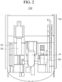
- FIG. 2 shows a nuclear facility
- the nuclear facility 1000 includes: a nuclear reactor pressure vessel 100; biodegradable concrete 300 for surrounding the nuclear reactor pressure vessel 100 and supporting the nuclear reactor pressure vessel 100; a surrounding facility 200, such as a steam generator, separated from the nuclear reactor pressure vessel 100 and the biodegradable concrete 300 and connected to the nuclear reactor pressure vessel 100; a concrete structure 400 separated from the nuclear reactor pressure vessel 100 and neighboring the biodegradable concrete 300 to support the surrounding facility 200 such as a steam generator; and a containment vessel 500 for containing the nuclear reactor pressure vessel 100, the biodegradable concrete 300, the surrounding facility 200, and the concrete structure 400.
- the nuclear reactor pressure vessel 100, the biodegradable concrete 300, the surrounding facility 200, the concrete structure 400, and the containment vessel 500 included in the nuclear facility 1000 may have various known configurations.
- the nuclear reactor pressure vessel 100 may be of a pressurized water reactor type, but is not limited thereto.
- the nuclear reactor pressure vessel 100 may be of a boiling water reactor type.
- the nuclear facility 1000 may have various forms when it includes the nuclear reactor pressure vessel 100, the biodegradable concrete 300, and the concrete structure 400.
- the nuclear reactor pressure vessel 100 positioned in the containment vessel 500 is separated from the biodegradable concrete 300.
- a pipe connected to the nuclear reactor pressure vessel 100 may be cut before the nuclear reactor pressure vessel 100 is separated from the biodegradable concrete 300.
- the surrounding facility 200 such as a steam generator positioned in the containment vessel 500 is separated from the concrete structure 400.
- a pipe connected to the surrounding facility 200 may be cut before the surrounding facility 200 is separated from the concrete structure 400.
- the concrete structure 400 is decommissioned (S200).
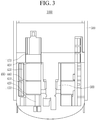
- the concrete structure 400 positioned in the containment vessel 500 and neighboring the biodegradable concrete 300 includes a first concrete layer 410, a first floor 420, a second concrete layer 430, a second floor 440, a third concrete layer 450, a third floor 460, and a fourth concrete layer 470 sequentially stacked from a bottom of the containment vessel 500.
- the concrete structure 400 is decommissioned in the containment vessel 500.
- the concrete structure 400 may be decommissioned by using a concrete cutting means such as a wire saw.
- the fourth concrete layer 470 around the biodegradable concrete 300 is decontaminated and decommissioned.
- the third floor 460 and the third concrete layer 450 positioned around the biodegradable concrete 300 are decontaminated and decommissioned.
- the second floor 440 and the second concrete layer 430 positioned around the biodegradable concrete 300 are decontaminated and decommissioned.
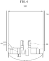
- the first floor 420 and the first concrete layer 410 positioned around the biodegradable concrete 300 are decontaminated and decommissioned.
- the biodegradable concrete 300 that is a highly radioactive area remains, and the concrete structure 400 positioned around the biodegradable concrete 300 is decommissioned, so contamination of the concrete structure 400 caused by decommissioning of the biodegradable concrete 300 is prevented.
- the concrete structure 400 and the biodegradable concrete 300 in the containment vessel 500 are decommissioned, the concrete structure 400 that is a lowly radioactive area is first decommissioned, so contamination of other structures caused by dust spreading generated when the biodegradable concrete 300 that is a highly radioactive area is decommissioned is prevented.
- the first concrete layer 410, the first floor 420, the second concrete layer 430, the second floor 440, the third concrete layer 450, the third floor 460, and the fourth concrete layer 470 included in the concrete structure 400 are decommissioned in order from the highest layer to the lowest layer while the biodegradable concrete 300 functions as a column, so there is no need to install an additional safety reinforcing structure, and a time for decommissioning the nuclear facility 1000 is minimized.
- the biodegradable concrete 300 is covered (S300).
- the biodegradable concrete 300 positioned in the containment vessel 500 is closed and sealed with a packing container 10.
- the packing container 10 may include various known materials when it may close and seal the biodegradable concrete 300.
- the packing container 10 is connected to a suction unit 20 including a pump.
- the biodegradable concrete 300 is decommissioned (S400).
- the biodegradable concrete 300 is decontaminated and decommissioned while internal air in the packing container 10 is suctioned by using the suction unit 20.
- the biodegradable concrete 300 is decommissioned in the packing container 10 positioned in the containment vessel 500.
- the biodegradable concrete 300 may be decommissioned by using a concrete cutting means such as a wire saw.
- the biodegradable concrete 300 is decommissioned while the biodegradable concrete 300 is closed and sealed by the packing container 10 and the internal air from the packing container 10 is suctioned, so the contamination of the inside of the containment vessel 500 caused by dust spreading generated when the biodegradable concrete 300 that is a highly radioactive area is decommissioned is prevented.
- the method for decommissioning a nuclear facility leaves the biodegradable concrete 300 that is a highly radioactive area and decommissions the concrete structure 400 positioned around the biodegradable concrete 300 when the concrete structure 400 positioned in the containment vessel 500 is decommissioned, thereby preventing contamination of the concrete structure 400 and contamination of the inside of the containment vessel 500 caused by a dust spreading according to decommissioning of the biodegradable concrete 300.
- the method for decommissioning a nuclear facility decommissions the concrete structure 400 around the biodegradable concrete 300 when the biodegradable concrete 300 positioned in the containment vessel 500 is decommissioned, closes and seals the biodegradable concrete 300 with the packing container 10, and decommissions the biodegradable concrete 300 while suctioning the internal air in the packing container 10, thereby contamination of the inside of the containment vessel 500 caused by dust spreading generated when the biodegradable concrete 300 that is a highly radioactive area is decommissioned.
- the method for decommissioning a nuclear facility for suppressing contamination of a peripheral area when the biodegradable concrete 300 is decommissioned is provided.
- the method for decommissioning a nuclear facility decommissions the concrete structure 400 in order from the highest layer to the lowest layer while the biodegradable concrete 300 that is not decommissioned functions as a column, when the concrete structure 400 is decommissioned, so there is no need to install an additional safety reinforcing structure, and a time for decommissioning the nuclear facility 1000 is minimized.
- the method for decommissioning a nuclear facility with a minimized time for decommissioning the nuclear facility 1000 is provided.
Landscapes
- Engineering & Computer Science (AREA)
- Physics & Mathematics (AREA)
- General Engineering & Computer Science (AREA)
- High Energy & Nuclear Physics (AREA)
- Plasma & Fusion (AREA)
- Life Sciences & Earth Sciences (AREA)
- Food Science & Technology (AREA)
- Working Measures On Existing Buildindgs (AREA)
- Processing Of Solid Wastes (AREA)
- Structure Of Emergency Protection For Nuclear Reactors (AREA)
Abstract
Description
- The present disclosure relates to a method for decommissioning nuclear facilities.
- In general, a nuclear power plant in a pressurized water reactor type from among nuclear facilities used for nuclear power generation includes a nuclear reactor pressure vessel, biodegradable concrete for supporting the nuclear reactor pressure vessel, surrounding facilities such as a steam generator connected to the nuclear reactor pressure vessel, and a concrete structure neighboring the biodegradable concrete and supporting the surrounding facilities.
- When the nuclear facilities are decommissioned, because the biodegradable concrete for supporting the nuclear reactor pressure vessel is radioactivated, when the biodegradable concrete is decommissioned, a non-radioactivated concrete structure neighboring the biodegradable concrete is contaminated.
- The above information disclosed in this Background section is only for enhancement of understanding of the background of the invention, and therefore it may contain information that does not form the prior art that is already known in this country to a person of ordinary skill in the art.
- The present invention has been made in an effort to provide a method for decommissioning a nuclear facility for suppressing contamination of a peripheral area when biodegradable concrete is decommissioned.
- The present invention has been made in another effort to provide a method for decommissioning a nuclear facility with a minimized decommissioning time.
- An exemplary embodiment of the present invention provides a method for decommissioning a nuclear facility including a nuclear reactor pressure vessel, a biodegradable concrete surrounding the nuclear reactor pressure vessel, and a concrete structure separated from the nuclear reactor pressure vessel and neighboring the biodegradable concrete, including: separating the nuclear reactor pressure vessel from the biodegradable concrete; decommissioning the concrete structure; covering the biodegradable concrete; and decommissioning the biodegradable concrete.
- The nuclear facility may further include a containment vessel for containing the nuclear reactor pressure vessel, the biodegradable concrete, and the concrete structure, and the concrete structure may be decommissioned and the biodegradable concrete may be decommissioned in the containment vessel.
- The concrete structure may include a first concrete layer, a first floor, a second concrete layer, a second floor, a third concrete layer, a third floor, and a fourth concrete layer that are sequentially stacked.
- The decommissioning of the concrete structure may include: decommissioning the fourth concrete layer; decommissioning the third floor and the third concrete layer; decommissioning the second floor and the second concrete layer; and decommissioning the first floor and the first concrete layer.
- The covering of the biodegradable concrete may be performed by closing and sealing the biodegradable concrete with a packing container.
- The decommissioning of the biodegradable concrete may be performed by suctioning internal air from the packing container.
- The nuclear reactor pressure vessel may be of a pressurized water reactor type.
- According to the exemplary embodiment, the method for decommissioning a nuclear facility for suppressing contamination of surroundings when biodegradable concrete is decommissioned is provided.
- Further, the method for decommissioning a nuclear facility with the minimized decommissioning time is provided.
-
-
FIG. 1 shows a flowchart of a method for decommissioning a nuclear facility according to an exemplary embodiment. -
FIG. 2 to FIG. 7 show a method for decommissioning a nuclear facility according to an exemplary embodiment. - The present invention will be described more fully hereinafter with reference to the accompanying drawings, in which exemplary embodiments of the invention are shown. As those skilled in the art would realize, the described embodiments may be modified in various different ways, all without departing from the scope of the present invention.
- Unless explicitly described to the contrary, the word "comprise" and variations such as "comprises" or "comprising" will be understood to imply the inclusion of stated elements but not the exclusion of any other elements.
- A method for decommissioning a nuclear facility according to an exemplary embodiment will now be described with reference to
FIG. 1 to FIG. 7 . - Hereinafter, a pressurized water reactor (PWR) type of nuclear power plant will be exemplified as the nuclear facility, and without being limited to this, the nuclear facility may be a boiling water reactor (BWR) type of nuclear power plant.
- The pressurized water reactor type of nuclear power plant uses light water as a coolant and a moderator, and uranium 235 is compressed by about 2 % to 4 % and is used as a nuclear fuel.
- The pressurized water reactor type of nuclear power plant may be distinguished into a facility relating to a nuclear reactor system for transmitting heat generated by nuclear fission in the nuclear reactor to a steam generator and exchanging heat, and a facility relating to a turbine and generator system for running the turbine with the steam generated by a steam generator, allowing it to pass through a condenser, reducing it into water, and circulating it to the steam generator.
- In general, a coolant (or light water) that is a heat transmitting medium of the nuclear reactor system is heated up to about 320 °C by the nuclear reactor, and is pressurized with about 153 atmospheres so that it may not be boiled.
- Devices configuring the system include a pressurizer for adjusting the pressure to maintain enthalpy, and a coolant pump for circulating the coolant between the nuclear reactor and the steam generator.
- The system for the steam generated by the steam generator to run the turbine and produce power from the generator connected to the turbine shaft may correspond to the principle of general thermoelectric power plants.
-
FIG. 1 shows a flowchart of a method for decommissioning a nuclear facility according to an exemplary embodiment.FIG. 2 to FIG. 7 show a method for decommissioning a nuclear facility according to an exemplary embodiment. - Referring to,
FIG. 1 andFIG. 2 , a nuclearreactor pressure vessel 100 is separated from biodegradable concrete 300 (S100). -
FIG. 2 shows a nuclear facility. - In detail, referring to
FIG. 2 , thenuclear facility 1000 includes: a nuclearreactor pressure vessel 100;biodegradable concrete 300 for surrounding the nuclearreactor pressure vessel 100 and supporting the nuclearreactor pressure vessel 100; a surroundingfacility 200, such as a steam generator, separated from the nuclearreactor pressure vessel 100 and thebiodegradable concrete 300 and connected to the nuclearreactor pressure vessel 100; aconcrete structure 400 separated from the nuclearreactor pressure vessel 100 and neighboring thebiodegradable concrete 300 to support the surroundingfacility 200 such as a steam generator; and acontainment vessel 500 for containing the nuclearreactor pressure vessel 100, thebiodegradable concrete 300, the surroundingfacility 200, and theconcrete structure 400. - The nuclear
reactor pressure vessel 100, thebiodegradable concrete 300, the surroundingfacility 200, theconcrete structure 400, and thecontainment vessel 500 included in thenuclear facility 1000 may have various known configurations. - The nuclear
reactor pressure vessel 100 may be of a pressurized water reactor type, but is not limited thereto. - For example, the nuclear
reactor pressure vessel 100 may be of a boiling water reactor type. - The
nuclear facility 1000 may have various forms when it includes the nuclearreactor pressure vessel 100, thebiodegradable concrete 300, and theconcrete structure 400. - First, to decommission the
nuclear facility 1000, the nuclearreactor pressure vessel 100 positioned in thecontainment vessel 500 is separated from thebiodegradable concrete 300. - A pipe connected to the nuclear
reactor pressure vessel 100 may be cut before the nuclearreactor pressure vessel 100 is separated from thebiodegradable concrete 300. - The surrounding
facility 200 such as a steam generator positioned in thecontainment vessel 500 is separated from theconcrete structure 400. - A pipe connected to the surrounding
facility 200 may be cut before the surroundingfacility 200 is separated from theconcrete structure 400. - To respectively separate the nuclear
reactor pressure vessel 100 and the surroundingfacility 200 from thebiodegradable concrete 300 and theconcrete structure 400, respective parts of thebiodegradable concrete 300 and theconcrete structure 400 may be cut. - Referring to
FIG. 3 to FIG. 6 , theconcrete structure 400 is decommissioned (S200). - In detail, referring to
FIG. 3 , theconcrete structure 400 positioned in thecontainment vessel 500 and neighboring thebiodegradable concrete 300 includes afirst concrete layer 410, afirst floor 420, asecond concrete layer 430, asecond floor 440, athird concrete layer 450, athird floor 460, and afourth concrete layer 470 sequentially stacked from a bottom of thecontainment vessel 500. - The
concrete structure 400 is decommissioned in thecontainment vessel 500. Theconcrete structure 400 may be decommissioned by using a concrete cutting means such as a wire saw. - The
fourth concrete layer 470 around thebiodegradable concrete 300 is decontaminated and decommissioned. - Referring to
FIG. 4 , thethird floor 460 and thethird concrete layer 450 positioned around thebiodegradable concrete 300 are decontaminated and decommissioned. - Referring to
FIG. 5 , thesecond floor 440 and thesecond concrete layer 430 positioned around thebiodegradable concrete 300 are decontaminated and decommissioned. - Referring to
FIG. 6 , thefirst floor 420 and thefirst concrete layer 410 positioned around thebiodegradable concrete 300 are decontaminated and decommissioned. - As described above, when the
concrete structure 400 is decommissioned, thebiodegradable concrete 300 that is a highly radioactive area remains, and theconcrete structure 400 positioned around thebiodegradable concrete 300 is decommissioned, so contamination of theconcrete structure 400 caused by decommissioning of thebiodegradable concrete 300 is prevented. - That is, when the
concrete structure 400 and thebiodegradable concrete 300 in thecontainment vessel 500 are decommissioned, theconcrete structure 400 that is a lowly radioactive area is first decommissioned, so contamination of other structures caused by dust spreading generated when thebiodegradable concrete 300 that is a highly radioactive area is decommissioned is prevented. - Further, when the
concrete structure 400 is decommissioned, thefirst concrete layer 410, thefirst floor 420, thesecond concrete layer 430, thesecond floor 440, thethird concrete layer 450, thethird floor 460, and thefourth concrete layer 470 included in theconcrete structure 400 are decommissioned in order from the highest layer to the lowest layer while thebiodegradable concrete 300 functions as a column, so there is no need to install an additional safety reinforcing structure, and a time for decommissioning thenuclear facility 1000 is minimized. - Referring to
FIG. 7 , thebiodegradable concrete 300 is covered (S300). - In detail, the
biodegradable concrete 300 positioned in thecontainment vessel 500 is closed and sealed with apacking container 10. Thepacking container 10 may include various known materials when it may close and seal thebiodegradable concrete 300. Thepacking container 10 is connected to asuction unit 20 including a pump. - The
biodegradable concrete 300 is decommissioned (S400). - In detail, the
biodegradable concrete 300 is decontaminated and decommissioned while internal air in thepacking container 10 is suctioned by using thesuction unit 20. - The
biodegradable concrete 300 is decommissioned in thepacking container 10 positioned in thecontainment vessel 500. - The
biodegradable concrete 300 may be decommissioned by using a concrete cutting means such as a wire saw. - The
biodegradable concrete 300 is decommissioned while thebiodegradable concrete 300 is closed and sealed by the packingcontainer 10 and the internal air from the packingcontainer 10 is suctioned, so the contamination of the inside of thecontainment vessel 500 caused by dust spreading generated when thebiodegradable concrete 300 that is a highly radioactive area is decommissioned is prevented. - As described above, the method for decommissioning a nuclear facility according to an exemplary embodiment leaves the
biodegradable concrete 300 that is a highly radioactive area and decommissions theconcrete structure 400 positioned around thebiodegradable concrete 300 when theconcrete structure 400 positioned in thecontainment vessel 500 is decommissioned, thereby preventing contamination of theconcrete structure 400 and contamination of the inside of thecontainment vessel 500 caused by a dust spreading according to decommissioning of thebiodegradable concrete 300. - In addition, the method for decommissioning a nuclear facility according to an exemplary embodiment decommissions the
concrete structure 400 around thebiodegradable concrete 300 when thebiodegradable concrete 300 positioned in thecontainment vessel 500 is decommissioned, closes and seals thebiodegradable concrete 300 with the packingcontainer 10, and decommissions thebiodegradable concrete 300 while suctioning the internal air in the packingcontainer 10, thereby contamination of the inside of thecontainment vessel 500 caused by dust spreading generated when thebiodegradable concrete 300 that is a highly radioactive area is decommissioned. - That is, the method for decommissioning a nuclear facility for suppressing contamination of a peripheral area when the
biodegradable concrete 300 is decommissioned is provided. - Further, the method for decommissioning a nuclear facility according to an exemplary embodiment decommissions the
concrete structure 400 in order from the highest layer to the lowest layer while thebiodegradable concrete 300 that is not decommissioned functions as a column, when theconcrete structure 400 is decommissioned, so there is no need to install an additional safety reinforcing structure, and a time for decommissioning thenuclear facility 1000 is minimized. - That is, the method for decommissioning a nuclear facility with a minimized time for decommissioning the
nuclear facility 1000 is provided. - While this invention has been described in connection with what is presently considered to be practical exemplary embodiments, it is to be understood that the invention is not limited to the disclosed embodiments, but, on the contrary, is intended to cover various modifications and equivalent arrangements included within the scope of the appended claims.
Claims (7)
- A method for decommissioning a nuclear facility including a nuclear reactor pressure vessel, biodegradable concrete surrounding the nuclear reactor pressure vessel, and a concrete structure separated from the nuclear reactor pressure vessel and neighboring the biodegradable concrete, comprising:separating the nuclear reactor pressure vessel from the biodegradable concrete;decommissioning the concrete structure;covering the biodegradable concrete; anddecommissioning the biodegradable concrete.
- The method of claim 1, wherein
the nuclear facility further includes a containment vessel for containing the nuclear reactor pressure vessel, the biodegradable concrete, and the concrete structure, and
the concrete structure is decommissioned and the biodegradable concrete is decommissioned in the containment vessel. - The method of claim 1, wherein
the concrete structure includes a first concrete layer, a first floor, a second concrete layer, a second floor, a third concrete layer, a third floor, and a fourth concrete layer that are sequentially stacked. - The method of claim 3, wherein
the decommissioning of the concrete structure includes:decommissioning the fourth concrete layer;decommissioning the third floor and the third concrete layer;decommissioning the second floor and the second concrete layer; anddecommissioning the first floor and the first concrete layer. - The method of claim 1, wherein
the covering of the biodegradable concrete is performed by closing and sealing the biodegradable concrete with a packing container. - The method of claim 5, wherein
the decommissioning of the biodegradable concrete is performed by suctioning internal air from the packing container. - The method of claim 1, wherein
the nuclear reactor pressure vessel is of a pressurized water reactor type.
Applications Claiming Priority (2)
| Application Number | Priority Date | Filing Date | Title |
|---|---|---|---|
| KR1020180045649A KR102092373B1 (en) | 2018-04-19 | 2018-04-19 | Method for decommissioning nuclear facilities |
| PCT/KR2019/004665 WO2019203582A1 (en) | 2018-04-19 | 2019-04-18 | Method for dismantling nuclear power facility |
Publications (2)
| Publication Number | Publication Date |
|---|---|
| EP3783624A1 true EP3783624A1 (en) | 2021-02-24 |
| EP3783624A4 EP3783624A4 (en) | 2022-01-26 |
Family
ID=68239781
Family Applications (1)
| Application Number | Title | Priority Date | Filing Date |
|---|---|---|---|
| EP19788648.4A Pending EP3783624A4 (en) | 2018-04-19 | 2019-04-18 | Method for dismantling nuclear power facility |
Country Status (5)
| Country | Link |
|---|---|
| US (1) | US11610695B2 (en) |
| EP (1) | EP3783624A4 (en) |
| JP (1) | JP7125508B2 (en) |
| KR (1) | KR102092373B1 (en) |
| WO (1) | WO2019203582A1 (en) |
Family Cites Families (12)
| Publication number | Priority date | Publication date | Assignee | Title |
|---|---|---|---|---|
| JPS6466371A (en) | 1987-09-08 | 1989-03-13 | Kajima Corp | Method of overhauling nuclear reactor |
| JP2857805B2 (en) * | 1990-10-22 | 1999-02-17 | 株式会社竹中工務店 | Large Blocking Cutting Method of Activated Part in Reactor Biological Shield Structure |
| US6586758B2 (en) | 2001-06-11 | 2003-07-01 | Biodex Medical Systems, Inc. | Radiopharmaceutical pig and transportation apparatus |
| JP4280921B2 (en) * | 2004-02-27 | 2009-06-17 | 株式会社Ihi | Nuclear reactor dismantling method |
| KR101024039B1 (en) | 2009-12-23 | 2011-03-22 | 한국원자력연구원 | Reactor Dismantling Method for Research Reactor |
| US8873696B2 (en) * | 2010-03-27 | 2014-10-28 | Special Applications Technology, Inc. | Systems and methods for dismantling a nuclear reactor |
| JP2012230084A (en) | 2011-04-27 | 2012-11-22 | Shimizu Corp | Method for dismantling nuclear power generation plant building |
| JP5986463B2 (en) | 2012-09-12 | 2016-09-06 | 日立Geニュークリア・エナジー株式会社 | Ventilation and air conditioning equipment for nuclear power plants |
| JP6424437B2 (en) * | 2014-02-13 | 2018-11-21 | 株式会社Ihi | Reactor removal method |
| US20160125963A1 (en) | 2014-10-29 | 2016-05-05 | Robin Jerry McDaniel | Intrinsically safe nuclear reactor |
| JP6480365B2 (en) * | 2015-09-29 | 2019-03-06 | 日立Geニュークリア・エナジー株式会社 | Reactor building demolition method |
| KR101662588B1 (en) | 2016-05-03 | 2016-10-05 | 인영건설 주식회사 | Cutting machine and cutting method using a dry wire saws for dismantling nuclear power plant construction |
-
2018
- 2018-04-19 KR KR1020180045649A patent/KR102092373B1/en active Active
-
2019
- 2019-04-18 EP EP19788648.4A patent/EP3783624A4/en active Pending
- 2019-04-18 JP JP2020557269A patent/JP7125508B2/en active Active
- 2019-04-18 WO PCT/KR2019/004665 patent/WO2019203582A1/en not_active Ceased
- 2019-04-18 US US17/048,317 patent/US11610695B2/en active Active
Also Published As
| Publication number | Publication date |
|---|---|
| WO2019203582A1 (en) | 2019-10-24 |
| EP3783624A4 (en) | 2022-01-26 |
| US11610695B2 (en) | 2023-03-21 |
| KR20190122028A (en) | 2019-10-29 |
| US20210158982A1 (en) | 2021-05-27 |
| JP7125508B2 (en) | 2022-08-24 |
| KR102092373B1 (en) | 2020-03-23 |
| JP2021518914A (en) | 2021-08-05 |
Similar Documents
| Publication | Publication Date | Title |
|---|---|---|
| EP2845202B1 (en) | A method of refueling a nuclear reactor | |
| US9773575B2 (en) | Passive filtration of air egressing from nuclear containment | |
| EP3631815B1 (en) | Very simplified boiling water reactors for commercial electricity generation | |
| CN109243634A (en) | Reactor safety system | |
| EP2955719B1 (en) | Nuclear power plant and reactor building gas treatment system | |
| Hannerz | Towards intrinsically safe light-water reactors | |
| US11610695B2 (en) | Method for decommissioning nuclear facilities | |
| Guidez et al. | New reactor safety measures for the european sodium fast reactor—part i: Conceptual design | |
| KR102128053B1 (en) | Method for decommissioning nuclear facilities | |
| JP2021518913A (en) | Systems and methods for dismantling and decontaminating bioprotective concrete in pressurized light water reactor nuclear power plants | |
| EP3669378B1 (en) | Simplified nuclear reactor system and method of manufacturing such system | |
| EP3783622A1 (en) | Method of decommissioning nuclear facility | |
| US11581101B2 (en) | Method for decommissioning nuclear facilities | |
| Narabayashi et al. | Development of high efficiency containment venting system by using AgX | |
| Luxat et al. | Nuclear Safety Enhancements bases on Daiichi Forensics Information. | |
| Matsumoto et al. | ICONE23-1645 ABWR3: Passive double confinement and SA population dose evaluation for the innovative ABWR | |
| Sato et al. | iB1350: Part 1—A Generation III. 7 Reactor iB1350 and Defense in Depth (DiD) | |
| Katoh et al. | Evaluation of External Event Effects on JSFR Fuel Handling System | |
| CN117976259A (en) | Small-sized nuclear power module | |
| Klein | Emergency-shutdown cooling towers: considerations in the evolution of optimum tower design | |
| Paton et al. | Decommissioning of Light Water Cooled Reactor Systems | |
| Jones et al. | The steam turbine retrofitting of six boiling water reactor units using innovative engineering and laser scanning techniques | |
| Gorgemans et al. | Westinghouse AP1000 plant, a generation III+ reactor | |
| Lee et al. | Decommissioning Design of Spent Fuel Pool Cooling and Cleanup System | |
| JPS6375595A (en) | turbine building |
Legal Events
| Date | Code | Title | Description |
|---|---|---|---|
| STAA | Information on the status of an ep patent application or granted ep patent |
Free format text: STATUS: THE INTERNATIONAL PUBLICATION HAS BEEN MADE |
|
| PUAI | Public reference made under article 153(3) epc to a published international application that has entered the european phase |
Free format text: ORIGINAL CODE: 0009012 |
|
| STAA | Information on the status of an ep patent application or granted ep patent |
Free format text: STATUS: REQUEST FOR EXAMINATION WAS MADE |
|
| 17P | Request for examination filed |
Effective date: 20201111 |
|
| AK | Designated contracting states |
Kind code of ref document: A1 Designated state(s): AL AT BE BG CH CY CZ DE DK EE ES FI FR GB GR HR HU IE IS IT LI LT LU LV MC MK MT NL NO PL PT RO RS SE SI SK SM TR |
|
| AX | Request for extension of the european patent |
Extension state: BA ME |
|
| DAV | Request for validation of the european patent (deleted) | ||
| DAX | Request for extension of the european patent (deleted) | ||
| A4 | Supplementary search report drawn up and despatched |
Effective date: 20220105 |
|
| RIC1 | Information provided on ipc code assigned before grant |
Ipc: G21F 9/28 20060101ALI20211222BHEP Ipc: G21D 1/00 20060101AFI20211222BHEP |
|
| STAA | Information on the status of an ep patent application or granted ep patent |
Free format text: STATUS: EXAMINATION IS IN PROGRESS |
|
| 17Q | First examination report despatched |
Effective date: 20241011 |