EP3783623A1 - Method for dismantling nuclear facility - Google Patents
Method for dismantling nuclear facility Download PDFInfo
- Publication number
- EP3783623A1 EP3783623A1 EP19788359.8A EP19788359A EP3783623A1 EP 3783623 A1 EP3783623 A1 EP 3783623A1 EP 19788359 A EP19788359 A EP 19788359A EP 3783623 A1 EP3783623 A1 EP 3783623A1
- Authority
- EP
- European Patent Office
- Prior art keywords
- pipes
- upper penetration
- nuclear
- pipe
- pressure vessel
- Prior art date
- Legal status (The legal status is an assumption and is not a legal conclusion. Google has not performed a legal analysis and makes no representation as to the accuracy of the status listed.)
- Granted
Links
Images



Classifications
-
- G—PHYSICS
- G21—NUCLEAR PHYSICS; NUCLEAR ENGINEERING
- G21D—NUCLEAR POWER PLANT
- G21D1/00—Details of nuclear power plant
- G21D1/003—Nuclear facilities decommissioning arrangements
-
- Y—GENERAL TAGGING OF NEW TECHNOLOGICAL DEVELOPMENTS; GENERAL TAGGING OF CROSS-SECTIONAL TECHNOLOGIES SPANNING OVER SEVERAL SECTIONS OF THE IPC; TECHNICAL SUBJECTS COVERED BY FORMER USPC CROSS-REFERENCE ART COLLECTIONS [XRACs] AND DIGESTS
- Y02—TECHNOLOGIES OR APPLICATIONS FOR MITIGATION OR ADAPTATION AGAINST CLIMATE CHANGE
- Y02E—REDUCTION OF GREENHOUSE GAS [GHG] EMISSIONS, RELATED TO ENERGY GENERATION, TRANSMISSION OR DISTRIBUTION
- Y02E30/00—Energy generation of nuclear origin
Definitions
- the present disclosure relates to a method for decommissioning a nuclear facility.
- a pressurized light water reactor type of nuclear power plant includes a reactor pressure vessel and a cavity in which the reactor pressure vessel is positioned, and includes biological shield concrete surrounding the reactor pressure vessel.
- An exemplary embodiment provides a method for decommissioning a nuclear facility, which can easily cut pipes that are directly connected with a nuclear pressure vessel and surrounded by a biological shield concrete.
- One aspect of the present invention provides a method for decommissioning a nuclear facility that includes a nuclear reactor pressure vessel, a plurality of pipes that are directly connected to the nuclear reactor pressure vessel, biological shield concrete that surrounds the plurality of pipes and the nuclear pressure vessel and includes a plurality of upper penetration holes that overlap the plurality of pipes, and a plurality of sandboxes that cover the plurality of upper penetration holes.
- the method includes: exposing the plurality of pipes through the plurality of upper penetration holes by removing the plurality of sandboxes; and cutting the plurality of pipes through the plurality of upper penetration holes.
- the exposing the plurality of upper penetration holes may be carried out by removing a sealant that seals between the plurality of sandboxes and the upper portion of the biological shield concrete, and separating the plurality of sandboxes from the plurality of upper penetration holes.
- the plurality of upper penetration holes may completely expose the plurality of pipes in a width direction.
- the cutting the plurality of pipes may be carried out by cutting the plurality of pipes in the width direction by using a wire saw or a circular saw.
- the method for decommissioning the nuclear facility may further include separating the nuclear pressure vessel from the biological shield concrete.
- the nuclear reactor pressure vessel may be a pressurized water reactor.
- a method for decommissioning a nuclear facility that can easily cut pipes that are directly connected to a nuclear pressure vessel and surrounded by a biological shield concrete can be provided.
- the present invention may be implemented in various different forms and is not limited to an exemplary embodiment described herein.
- a pressurized water reactor (PWR) type of nuclear power plant will be described as an example of a nuclear facility, but this is not restrictive, and the nuclear facility may be a boiling water reactor (BWR) type of nuclear power plant.
- PWR pressurized water reactor
- BWR boiling water reactor
- the PWR-type nuclear power plant uses light water as a coolant and a moderator, and uses uranium 235 concentrated to about 2 % to 4 % as nuclear fuel.
- the PWR-type nuclear power plant may be divided into a facility related to the nuclear reactor system that sends heat generated by nuclear fission within the reactor to a steam generator for heat exchange, and a facility related to a turbine and a generator system which turns the turbine with the steam generated from the steam generator and condenses the steam to water through a condenser and then the water is circulated back to the steam generator.
- a coolant which is a heat transfer medium of a nuclear reactor system, is heated to about 320 °C in a nuclear reactor and pressurized to about 153 atmospheres so that it does not boil.
- a device that forms the system includes a pressurizer that adjusts pressure to maintain constant enthalpy, and a coolant pump that circulates the coolant between the reactor and the steam generator.
- the system in which the steam generated from the steam generator rotates the turbine and generates power from the generator connected to the turbine shaft may be the same as the principle of a general thermal power plant.
- FIG. 1 is a flowchart of a decommission method of a nuclear facility according to an exemplary embodiment.
- FIG. 2 to FIG. 5 are provided for description of the decommission method of the nuclear facility according to the exemplary embodiment.
- a plurality of pipes 200 are exposed through a plurality of upper penetration holes 420 by removing a plurality of sandboxes 500 (S100).
- FIG. 2 shows a nuclear facility
- a nuclear facility 1000 includes a nuclear reactor pressure vessel 100, a plurality of pipes 200 that are directly connected with the nuclear reactor pressure vessel 100, steam generators 300 that are connected with the nuclear reactor pressure vessel 100 through the pipes 200, biological shield concrete 400 that support the nuclear reactor pressure vessel 100 while surrounding the nuclear reactor pressure vessel 100 and the pipes 200, and a plurality of sandboxes 500.
- the nuclear reactor pressure vessel 100 may be a pressurized light-water reactor, but this is not restrictive.
- the nuclear reactor pressure vessel 100 may be a boiling water reactor.
- the nuclear facility 1000 may be formed in various shapes when it includes the nuclear reactor pressure vessel 100, the pipes 200, the biological shield concrete 400, and the sandboxes 500.
- the biological shield concrete 400 includes a cavity where the nuclear reactor pressure vessel 100 is located, and a plurality of upper penetration holes 420 that expose the pipes 200 by overlapping the pipes 200.
- the upper penetration holes 420 of the biological shield concrete 400 may correspond to welding portions between the pipes 200 and nozzles of the nuclear reactor pressure vessel 100, but this is not restrictive.
- the sandboxes 500 cover the upper penetration holes 420.
- the sandboxes 500 may have a box shape filled with sand, but is not limited thereto.
- An upper flange to be supported on an upper portion of the biological shield concrete 400 of the sandboxes 500 may be included, and the upper flange may be supported on the upper portion of the biological shield concrete 400.
- the sandboxes 500 are supported on the upper portion of the biological shield concrete 400, and sealants may be provided between the sandboxes 500 and the upper portions of the biological shield concrete 400.
- the sandbox 500 may be a structure for easily checking the integrity of the pipe 200 that is directly connected to the nuclear reactor pressure vessel 100.
- the sandboxes 500 are separated from the upper penetration holes 420 of the biological shield concrete 400, and the integrity of the pipes 200 exposed by the upper penetration holes 420 can be checked.
- the above described nuclear reactor pressure vessel 100, the pipes 200, the steam generator 300, the biological shield concrete 400, and the sandboxes 500 may be disposed in a containment vessel.
- FIG. 3 shows the upper portion of the biological shield concrete of the nuclear facility.
- the pipes 200 connected to the nuclear reactor pressure vessel 100 that is disposed in the cavity 420 of the biological shield concrete 400 include a first pipe 201, a second pipe 202, a third pipe 203, and a fourth pipe 204
- the first pipe 201 and the second pipe 202 are connected with one steam generator, and the third pipe 203 and the fourth pipe 204 are connected with another steam generator.
- Hot water may pass through the first pipe 201 and the third pipe 203, and cold water may pass through the second pipe 202 and the fourth pipe 204, but this is not restrictive.
- the upper penetration holes 420 of the biological shield concrete 400 are separated from each other in the upper portion of the biological shield concrete 400.
- the upper penetration hole 420 has a quadrangular shape on a plane.
- the upper penetration holes 420 includes a first upper penetration hole 421, a second upper penetration hole 422, a third upper penetration hole 423, and a fourth upper penetration hole 424.
- the first upper penetration hole 421 exposes the first pipe 201 by overlapping the first pipe 201.
- the second upper penetration hole 422 exposes the second pipe 202 by overlapping the second pipe 202.
- the third upper penetration hole 423 exposes the third pipe 203 by overlapping the third pipe 203.
- the fourth upper penetration hole 424 exposes the fourth pipe 204 by overlapping the fourth pipe 204.
- the upper penetration holes 420 completely expose the pipes 200 in the width direction of each pipe.
- first upper penetration hole 421, the second upper penetration hole 422, the third upper penetration hole 423, and the fourth upper penetration hole 424 respectively completely expose the first pipe 201, the second pipe 202, the third pipe 203, and the fourth pipe 204 respectively in width directions of the respective pipes.
- the sandboxes 500 are separated from each other in the upper portion of the biological shield concrete 400.
- the sandbox 500 has a quadrangular shape on a plane.
- the sandboxes 500 include a first sandbox 501, a second sandbox 502, a third sandbox 503, and a fourth sandbox 504.
- the first sandbox 501 is disposed inside the first upper penetration hole 421 and covers the first upper penetration hole 421.
- the second sandbox 502 is disposed inside the second upper penetration hole 422 and covers the second upper penetration hole 422.
- the third sandbox 503 is disposed inside the third upper penetration hole 423 and covers the third upper penetration hole 423.
- the fourth sandbox 504 is disposed inside the fourth upper penetration hole 424 and overs the fourth upper penetration hole 424.
- Each of the first sandbox 501, the second sandbox 502, the third sandbox 503, and the fourth sandbox 504 may be a structure for determining integrity of each of the first pipe 201, the second pipe 202, the third pipe 203, and the fourth pipe 204.
- the first sandbox 501, the second sandbox 502, the third sandbox 503, and the fourth sandbox 504 are respectively separated from the first upper penetration hole 421, the second upper penetration hole 422, the third upper penetration hole 423, and the fourth upper penetration hole 424 of the biological shield concrete 400, and integrity of each of the first pipe 201, the second pipe 202, the third pipe 203, and the fourth pipe 204, which are respectively exposed by the first upper penetration hole 421, the second upper penetration hole 422, the third upper penetration hole 423, and the fourth upper penetration hole 424, can be determined.
- the plurality of sandboxes 500 which are the first sandbox 501, the second sandbox 502, the third sandbox 503, and the fourth sandbox 504 are respectively separated from the plurality of upper penetration holes 420, which are the first upper penetration hole 421, the second upper penetration hole 422, the third upper penetration hole 423, and the fourth upper penetration hole 424.
- the plurality of upper penetration holes 420 which are the first upper penetration hole 421, the second upper penetration hole 422, the third upper penetration hole 423, and the fourth upper penetration hole 424, are exposed, and the first pipe 201, the second pipe 202, the third pipe 203, and the fourth pipe 204 are respectively exposed through the first upper penetration hole 421, the second upper penetration hole 422, third upper penetration hole 423, and fourth upper penetration hole 424.
- the first pipe 201, the second pipe 202, the third pipe 203, and the fourth pipe 204 are completely exposed in width directions of the respective pipes through the first upper penetration hole 421, the second upper penetration hole 422, the third upper penetration hole 423, and the fourth upper penetration hole 424.
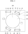
- the pipes 200 completely exposed in the width direction through the upper penetration holes 420 are cut along virtual cut lines CL extending in the width direction of the pipes 200.
- the first pipe 201 exposed through the first upper penetration holes 4201 is cut along a cut ling CL extending in a width direction of the first pipe 201
- the second pipe 202 exposed through the second upper penetration hole 422 is cut along a cut ling CL extending in a width direction of the second pipe 202
- the third pipe 203 exposed through the third upper penetration hole 423 is cut along a cut line CL extending in a width direction of the third pipe 203
- the fourth pipe 204 exposed through the fourth upper penetration hole 424 is cut along a cut line CL extending in a width direction of the fourth pipe 204.
- the pipes 200 may be cut using a wire saw, but the present invention is not limited thereto, and the pipes 200 may be cut using other cutting means such as a circular saw and the like.
- the pipes 200 can be easily cut through the upper penetration holes 420 by using a cutting means.
- the nuclear reactor pressure vessel 100 is separated from the biological shield concrete 400 (S300).
- the nuclear reactor pressure vessel 100 of which the pipes connected thereto are cut is separated from the biological shield concrete 400 through the enlarged upper space of the cavity 410 of the biological shield concrete 400.
- the reactor pressure vessel 100 can be easily separated from the biological shield concrete 400 without interference between the biological shield concrete 400 and the pipes.
- the pipes 200 when the pipes 200 that are directly connected to the reactor pressure vessel 100 are cut, the pipes 200 are completely exposed in the width direction through the upper penetration holes 420 by separating the sandboxes 500 for determining integrity of the pipes 200 from the upper penetration holes 420 of the biological shield concrete 400, which are provided for determining integrity of the pipes 200, from the upper penetration holes 420 of the biological shield concrete 400 without forming separate holes in the biological shield concrete 400 such that a work space for cutting the pipes 200 can be assured, thereby easily cutting the pipes 200 connected with the nuclear reactor pressure vessel 100.
- the pipes 200 disposed inside the biological shield concrete 400 are cut through the upper penetration holes 420 that are exposed by separating the sandboxes 500, and the nuclear reactor pressure vessel 100 and the steam generator are separated from the biological shield concrete 400 such that the decommission process time can be shortened by using the sandboxes 500 without performing separate work for decommissioning of the biological shield concrete 400.
- a method for decommissioning the nuclear facility that can reduce time for decommissioning the nuclear facility and cost for decommission by easily cutting the pipes 300 that are directly connected to the nuclear pressure vessel 100 and surrounded by the biological shield concrete 400 is provided.
Landscapes
- Physics & Mathematics (AREA)
- Engineering & Computer Science (AREA)
- Plasma & Fusion (AREA)
- General Engineering & Computer Science (AREA)
- High Energy & Nuclear Physics (AREA)
- Working Measures On Existing Buildindgs (AREA)
Abstract
Description
- The present disclosure relates to a method for decommissioning a nuclear facility.
- In general, among nuclear facilities used for nuclear power generation, a pressurized light water reactor type of nuclear power plant includes a reactor pressure vessel and a cavity in which the reactor pressure vessel is positioned, and includes biological shield concrete surrounding the reactor pressure vessel.
- In decommissioning of a nuclear facility, it is necessary to expand a space above the cavity to secure a working space in order to easily separate the reactor pressure vessel from the biological shield concrete.
- An exemplary embodiment provides a method for decommissioning a nuclear facility, which can easily cut pipes that are directly connected with a nuclear pressure vessel and surrounded by a biological shield concrete.
- One aspect of the present invention provides a method for decommissioning a nuclear facility that includes a nuclear reactor pressure vessel, a plurality of pipes that are directly connected to the nuclear reactor pressure vessel, biological shield concrete that surrounds the plurality of pipes and the nuclear pressure vessel and includes a plurality of upper penetration holes that overlap the plurality of pipes, and a plurality of sandboxes that cover the plurality of upper penetration holes. The method includes: exposing the plurality of pipes through the plurality of upper penetration holes by removing the plurality of sandboxes; and cutting the plurality of pipes through the plurality of upper penetration holes.
- The exposing the plurality of upper penetration holes may be carried out by removing a sealant that seals between the plurality of sandboxes and the upper portion of the biological shield concrete, and separating the plurality of sandboxes from the plurality of upper penetration holes.
- The plurality of upper penetration holes may completely expose the plurality of pipes in a width direction.
- The cutting the plurality of pipes may be carried out by cutting the plurality of pipes in the width direction by using a wire saw or a circular saw.
- The method for decommissioning the nuclear facility may further include separating the nuclear pressure vessel from the biological shield concrete.
- The nuclear reactor pressure vessel may be a pressurized water reactor.
- According to the exemplary embodiment, a method for decommissioning a nuclear facility that can easily cut pipes that are directly connected to a nuclear pressure vessel and surrounded by a biological shield concrete can be provided.
-
-
FIG. 1 is a flowchart of a decommission method of a nuclear facility according to an exemplary embodiment. -
FIG. 2 to FIG. 5 are provided for description of the decommission method of the nuclear facility according to the exemplary embodiment. - Hereinafter, an exemplary embodiment of the present invention will be described in detail with reference to the accompanying drawing so that a person of ordinary skill in the art to which the present invention belongs can easily implement it.
- The present invention may be implemented in various different forms and is not limited to an exemplary embodiment described herein.
- In addition, unless explicitly described to the contrary, the word "comprise", and variations such as "comprises" or "comprising" will be understood to imply the inclusion of stated elements but not the exclusion of any other elements.
- Hereinafter, referring to
FIG. 1 to FIG. 5 , a decommissioning method of a nuclear facility according to an exemplary embodiment will be described. - Hereinafter, a pressurized water reactor (PWR) type of nuclear power plant will be described as an example of a nuclear facility, but this is not restrictive, and the nuclear facility may be a boiling water reactor (BWR) type of nuclear power plant.
- The PWR-type nuclear power plant uses light water as a coolant and a moderator, and uses uranium 235 concentrated to about 2 % to 4 % as nuclear fuel.
- The PWR-type nuclear power plant may be divided into a facility related to the nuclear reactor system that sends heat generated by nuclear fission within the reactor to a steam generator for heat exchange, and a facility related to a turbine and a generator system which turns the turbine with the steam generated from the steam generator and condenses the steam to water through a condenser and then the water is circulated back to the steam generator.
- In general, a coolant (light water), which is a heat transfer medium of a nuclear reactor system, is heated to about 320 °C in a nuclear reactor and pressurized to about 153 atmospheres so that it does not boil.
- A device that forms the system includes a pressurizer that adjusts pressure to maintain constant enthalpy, and a coolant pump that circulates the coolant between the reactor and the steam generator.
- The system in which the steam generated from the steam generator rotates the turbine and generates power from the generator connected to the turbine shaft may be the same as the principle of a general thermal power plant.
-
FIG. 1 is a flowchart of a decommission method of a nuclear facility according to an exemplary embodiment. -
FIG. 2 to FIG. 5 are provided for description of the decommission method of the nuclear facility according to the exemplary embodiment. - First, referring to
FIG. 1 to FIG. 3 , a plurality ofpipes 200 are exposed through a plurality ofupper penetration holes 420 by removing a plurality of sandboxes 500 (S100). -
FIG. 2 shows a nuclear facility. - Specifically, referring to
FIG. 2 , anuclear facility 1000 includes a nuclearreactor pressure vessel 100, a plurality ofpipes 200 that are directly connected with the nuclearreactor pressure vessel 100,steam generators 300 that are connected with the nuclearreactor pressure vessel 100 through thepipes 200,biological shield concrete 400 that support the nuclearreactor pressure vessel 100 while surrounding the nuclearreactor pressure vessel 100 and thepipes 200, and a plurality ofsandboxes 500. - The nuclear
reactor pressure vessel 100 may be a pressurized light-water reactor, but this is not restrictive. - For example, the nuclear
reactor pressure vessel 100 may be a boiling water reactor. - The
nuclear facility 1000 may be formed in various shapes when it includes the nuclearreactor pressure vessel 100, thepipes 200, thebiological shield concrete 400, and thesandboxes 500. - The
biological shield concrete 400 includes a cavity where the nuclearreactor pressure vessel 100 is located, and a plurality ofupper penetration holes 420 that expose thepipes 200 by overlapping thepipes 200. - The
upper penetration holes 420 of thebiological shield concrete 400 may correspond to welding portions between thepipes 200 and nozzles of the nuclearreactor pressure vessel 100, but this is not restrictive. - The
sandboxes 500 cover theupper penetration holes 420. - The
sandboxes 500 may have a box shape filled with sand, but is not limited thereto. - An upper flange to be supported on an upper portion of the
biological shield concrete 400 of thesandboxes 500 may be included, and the upper flange may be supported on the upper portion of thebiological shield concrete 400. - The
sandboxes 500 are supported on the upper portion of thebiological shield concrete 400, and sealants may be provided between thesandboxes 500 and the upper portions of thebiological shield concrete 400. - The
sandbox 500 may be a structure for easily checking the integrity of thepipe 200 that is directly connected to the nuclearreactor pressure vessel 100. - For example, when the operation of the
nuclear facility 1000 is stopped, thesandboxes 500 are separated from theupper penetration holes 420 of thebiological shield concrete 400, and the integrity of thepipes 200 exposed by theupper penetration holes 420 can be checked. - The above described nuclear
reactor pressure vessel 100, thepipes 200, thesteam generator 300, thebiological shield concrete 400, and thesandboxes 500 may be disposed in a containment vessel. -
FIG. 3 shows the upper portion of the biological shield concrete of the nuclear facility. - Referring to
FIG. 3 , thepipes 200 connected to the nuclearreactor pressure vessel 100 that is disposed in thecavity 420 of thebiological shield concrete 400 include afirst pipe 201, asecond pipe 202, athird pipe 203, and afourth pipe 204 - The
first pipe 201 and thesecond pipe 202 are connected with one steam generator, and thethird pipe 203 and thefourth pipe 204 are connected with another steam generator. - Hot water may pass through the
first pipe 201 and thethird pipe 203, and cold water may pass through thesecond pipe 202 and thefourth pipe 204, but this is not restrictive. - The
upper penetration holes 420 of thebiological shield concrete 400 are separated from each other in the upper portion of thebiological shield concrete 400. - The
upper penetration hole 420 has a quadrangular shape on a plane. - The
upper penetration holes 420 includes a firstupper penetration hole 421, a secondupper penetration hole 422, a thirdupper penetration hole 423, and a fourthupper penetration hole 424. - The first
upper penetration hole 421 exposes thefirst pipe 201 by overlapping thefirst pipe 201. - The second
upper penetration hole 422 exposes thesecond pipe 202 by overlapping thesecond pipe 202. - The third
upper penetration hole 423 exposes thethird pipe 203 by overlapping thethird pipe 203. - The fourth
upper penetration hole 424 exposes thefourth pipe 204 by overlapping thefourth pipe 204. - The
upper penetration holes 420 completely expose thepipes 200 in the width direction of each pipe. - Specifically, the first
upper penetration hole 421, the secondupper penetration hole 422, the thirdupper penetration hole 423, and the fourthupper penetration hole 424 respectively completely expose thefirst pipe 201, thesecond pipe 202, thethird pipe 203, and thefourth pipe 204 respectively in width directions of the respective pipes. - The
sandboxes 500 are separated from each other in the upper portion of thebiological shield concrete 400. - The
sandbox 500 has a quadrangular shape on a plane. - The
sandboxes 500 include afirst sandbox 501, asecond sandbox 502, athird sandbox 503, and afourth sandbox 504. - The
first sandbox 501 is disposed inside the firstupper penetration hole 421 and covers the firstupper penetration hole 421. - The
second sandbox 502 is disposed inside the secondupper penetration hole 422 and covers the secondupper penetration hole 422. - The
third sandbox 503 is disposed inside the thirdupper penetration hole 423 and covers the thirdupper penetration hole 423. - The
fourth sandbox 504 is disposed inside the fourthupper penetration hole 424 and overs the fourthupper penetration hole 424. - Each of the
first sandbox 501, thesecond sandbox 502, thethird sandbox 503, and thefourth sandbox 504 may be a structure for determining integrity of each of thefirst pipe 201, thesecond pipe 202, thethird pipe 203, and thefourth pipe 204. - For example, when the operation of the
nuclear facility 1000 is stopped, thefirst sandbox 501, thesecond sandbox 502, thethird sandbox 503, and thefourth sandbox 504 are respectively separated from the firstupper penetration hole 421, the secondupper penetration hole 422, the thirdupper penetration hole 423, and the fourthupper penetration hole 424 of thebiological shield concrete 400, and integrity of each of thefirst pipe 201, thesecond pipe 202, thethird pipe 203, and thefourth pipe 204, which are respectively exposed by the firstupper penetration hole 421, the secondupper penetration hole 422, the thirdupper penetration hole 423, and the fourthupper penetration hole 424, can be determined. - First, for decommissioning of the
nuclear facility 1000, the plurality ofsandboxes 500, which are thefirst sandbox 501, thesecond sandbox 502, thethird sandbox 503, and thefourth sandbox 504 are respectively separated from the plurality of upper penetration holes 420, which are the firstupper penetration hole 421, the secondupper penetration hole 422, the thirdupper penetration hole 423, and the fourthupper penetration hole 424. - In this case, the sealant provided between the
sandboxes 500 and thebiological shield concrete 400 is removed. - Thus, the plurality of upper penetration holes 420, which are the first
upper penetration hole 421, the secondupper penetration hole 422, the thirdupper penetration hole 423, and the fourthupper penetration hole 424, are exposed, and thefirst pipe 201, thesecond pipe 202, thethird pipe 203, and thefourth pipe 204 are respectively exposed through the firstupper penetration hole 421, the secondupper penetration hole 422, thirdupper penetration hole 423, and fourthupper penetration hole 424. - The
first pipe 201, thesecond pipe 202, thethird pipe 203, and thefourth pipe 204 are completely exposed in width directions of the respective pipes through the firstupper penetration hole 421, the secondupper penetration hole 422, the thirdupper penetration hole 423, and the fourthupper penetration hole 424. - Next, referring to
FIG. 4 , the plurality ofpipes 200 exposed through the plurality of upper penetration holes 420 are cut (S200). - Specifically, the
pipes 200 completely exposed in the width direction through the upper penetration holes 420 are cut along virtual cut lines CL extending in the width direction of thepipes 200. - The
first pipe 201 exposed through the first upper penetration holes 4201is cut along a cut ling CL extending in a width direction of thefirst pipe 201, thesecond pipe 202 exposed through the secondupper penetration hole 422 is cut along a cut ling CL extending in a width direction of thesecond pipe 202, thethird pipe 203 exposed through the thirdupper penetration hole 423 is cut along a cut line CL extending in a width direction of thethird pipe 203, and thefourth pipe 204 exposed through the fourthupper penetration hole 424 is cut along a cut line CL extending in a width direction of thefourth pipe 204. - The
pipes 200 may be cut using a wire saw, but the present invention is not limited thereto, and thepipes 200 may be cut using other cutting means such as a circular saw and the like. - Since the
pipes 200 are completely exposed through the upper penetration holes 420 in the width direction, thepipes 200 can be easily cut through the upper penetration holes 420 by using a cutting means. - Next, referring to
FIG. 5 , the nuclearreactor pressure vessel 100 is separated from the biological shield concrete 400 (S300). - Specifically, the nuclear
reactor pressure vessel 100 of which the pipes connected thereto are cut is separated from thebiological shield concrete 400 through the enlarged upper space of thecavity 410 of thebiological shield concrete 400. - In addition, since pipes connected with the
reactor pressure vessel 100 are in the cut state through the upper penetration holes 420, thereactor pressure vessel 100 can be easily separated from thebiological shield concrete 400 without interference between thebiological shield concrete 400 and the pipes. - In addition, since pipes connected with the
reactor pressure vessel 100 and a steam generator are in the cut state through the upper penetration holes 420, the steam generator can be easily separated from thebiological shield concrete 400 without interference between thebiological shield concrete 400 and the pipes. - As described, in the method for decommissioning the nuclear facility according to the exemplary embodiment, when the
pipes 200 that are directly connected to thereactor pressure vessel 100 are cut, thepipes 200 are completely exposed in the width direction through the upper penetration holes 420 by separating thesandboxes 500 for determining integrity of thepipes 200 from the upper penetration holes 420 of thebiological shield concrete 400, which are provided for determining integrity of thepipes 200, from the upper penetration holes 420 of thebiological shield concrete 400 without forming separate holes in thebiological shield concrete 400 such that a work space for cutting thepipes 200 can be assured, thereby easily cutting thepipes 200 connected with the nuclearreactor pressure vessel 100. - In addition, in the method for decommissioning the nuclear facility according to the exemplary embodiment, the
pipes 200 disposed inside thebiological shield concrete 400 are cut through the upper penetration holes 420 that are exposed by separating thesandboxes 500, and the nuclearreactor pressure vessel 100 and the steam generator are separated from thebiological shield concrete 400 such that the decommission process time can be shortened by using thesandboxes 500 without performing separate work for decommissioning of thebiological shield concrete 400. - That is, a method for decommissioning the nuclear facility that can reduce time for decommissioning the nuclear facility and cost for decommission by easily cutting the
pipes 300 that are directly connected to thenuclear pressure vessel 100 and surrounded by thebiological shield concrete 400 is provided. - While this invention has been described in connection with what is presently considered to be practical exemplary embodiments, it is to be understood that the invention is not limited to the disclosed embodiments. On the contrary, it is intended to cover various modifications and equivalent arrangements included within the scope of the appended claims.
Claims (6)
- A method for decommissioning a nuclear facility that includes a nuclear reactor pressure vessel, a plurality of pipes that are directly connected to the nuclear reactor pressure vessel, biological shield concrete that surrounds the plurality of pipes and the nuclear pressure vessel and includes a plurality of upper penetration holes that overlap the plurality of pipes, and a plurality of sandboxes that cover the plurality of upper penetration holes, comprising:exposing the plurality of pipes through the plurality of upper penetration holes by removing the plurality of sandboxes; andcutting the plurality of pipes through the plurality of upper penetration holes.
- The method for decommissioning the nuclear facility of claim 1, wherein:
the exposing the plurality of upper penetration holes is carried out by removing a sealant that seals between the plurality of sandboxes and the upper portion of the biological shield concrete, and separating the plurality of sandboxes from the plurality of upper penetration holes. - The method for decommissioning the nuclear facility of claim 1, wherein the plurality of upper penetration holes completely expose the plurality of pipes in a width direction.
- The method for decommissioning the nuclear facility of claim 3, wherein the cutting the plurality of pipes is carried out by cutting the plurality of pipes in the width direction by using a wire saw or a circular saw.
- The method for decommissioning the nuclear facility of claim 1, further comprising separating the nuclear pressure vessel from the biological shield concrete.
- The method for decommissioning the nuclear facility of claim 1, wherein the nuclear reactor pressure vessel is a pressurized water reactor.
Applications Claiming Priority (2)
| Application Number | Priority Date | Filing Date | Title |
|---|---|---|---|
| KR1020180045648A KR102071567B1 (en) | 2018-04-19 | 2018-04-19 | Method for decommissioning nuclear facilities |
| PCT/KR2019/004664 WO2019203581A1 (en) | 2018-04-19 | 2019-04-18 | Method for dismantling nuclear facility |
Publications (3)
| Publication Number | Publication Date |
|---|---|
| EP3783623A1 true EP3783623A1 (en) | 2021-02-24 |
| EP3783623A4 EP3783623A4 (en) | 2022-01-26 |
| EP3783623B1 EP3783623B1 (en) | 2025-02-12 |
Family
ID=68239911
Family Applications (1)
| Application Number | Title | Priority Date | Filing Date |
|---|---|---|---|
| EP19788359.8A Active EP3783623B1 (en) | 2018-04-19 | 2019-04-18 | Method for decommissioning nuclear facilities |
Country Status (5)
| Country | Link |
|---|---|
| US (1) | US11581101B2 (en) |
| EP (1) | EP3783623B1 (en) |
| JP (1) | JP6975348B2 (en) |
| KR (1) | KR102071567B1 (en) |
| WO (1) | WO2019203581A1 (en) |
Family Cites Families (14)
| Publication number | Priority date | Publication date | Assignee | Title |
|---|---|---|---|---|
| US2716705A (en) * | 1945-03-27 | 1955-08-30 | Walter H Zinn | Radiation shield |
| US3755079A (en) * | 1969-12-12 | 1973-08-28 | Atomic Energy Commission | Nuclear reactor plant with integral entombment |
| JPS5368709A (en) | 1976-12-01 | 1978-06-19 | Kuraray Co Ltd | Preparation of butanediols |
| JPS5923298A (en) * | 1982-07-30 | 1984-02-06 | 清水建設株式会社 | Method of cutting pipe of reactor |
| JPH02307097A (en) * | 1989-05-23 | 1990-12-20 | Toda Constr Co Ltd | Dismantling method and device for shielding in nuclear reactor |
| JP2857805B2 (en) * | 1990-10-22 | 1999-02-17 | 株式会社竹中工務店 | Large Blocking Cutting Method of Activated Part in Reactor Biological Shield Structure |
| JPH07218696A (en) | 1994-02-08 | 1995-08-18 | Ishikawajima Harima Heavy Ind Co Ltd | New Reactor Pressure Vessel Replacement Method |
| JP3565371B2 (en) | 1995-04-14 | 2004-09-15 | 石川島播磨重工業株式会社 | How to replace the reactor pressure vessel |
| US5754612A (en) * | 1995-04-24 | 1998-05-19 | General Electric Company | Joint for interfacing steel head closure and prestressed concrete reactor vessel |
| SE520503C2 (en) | 1997-04-21 | 2003-07-15 | Westinghouse Atom Ab | Nuclear reactor device and way to build a nuclear reactor device |
| US6815695B2 (en) | 2002-01-28 | 2004-11-09 | Nikon Corporation | Simplified reticle stage removal system for an electron beam system |
| US20110255650A1 (en) | 2010-03-31 | 2011-10-20 | Mcdaniel Robin Jerry | Bi-stable nuclear reactor |
| JP2016114486A (en) * | 2014-12-16 | 2016-06-23 | 株式会社Ihi | Recovery method and recovery system of fuel debris |
| KR101662588B1 (en) | 2016-05-03 | 2016-10-05 | 인영건설 주식회사 | Cutting machine and cutting method using a dry wire saws for dismantling nuclear power plant construction |
-
2018
- 2018-04-19 KR KR1020180045648A patent/KR102071567B1/en active Active
-
2019
- 2019-04-18 US US17/048,332 patent/US11581101B2/en active Active
- 2019-04-18 EP EP19788359.8A patent/EP3783623B1/en active Active
- 2019-04-18 JP JP2020557280A patent/JP6975348B2/en active Active
- 2019-04-18 WO PCT/KR2019/004664 patent/WO2019203581A1/en not_active Ceased
Also Published As
| Publication number | Publication date |
|---|---|
| EP3783623A4 (en) | 2022-01-26 |
| JP6975348B2 (en) | 2021-12-01 |
| KR20190122027A (en) | 2019-10-29 |
| US11581101B2 (en) | 2023-02-14 |
| EP3783623B1 (en) | 2025-02-12 |
| WO2019203581A1 (en) | 2019-10-24 |
| US20210158984A1 (en) | 2021-05-27 |
| KR102071567B1 (en) | 2020-01-30 |
| JP2021519935A (en) | 2021-08-12 |
Similar Documents
| Publication | Publication Date | Title |
|---|---|---|
| KR102570118B1 (en) | System for decommissioning nuclear facilities | |
| US11495364B2 (en) | Method for decommissioning nuclear facilities | |
| EP3783623B1 (en) | Method for decommissioning nuclear facilities | |
| US12125602B2 (en) | Method for decommissioning nuclear facility | |
| EP3937189B1 (en) | Method for decommissioning nuclear facilities | |
| US11848114B2 (en) | Method for dismantling nuclear facility underwater | |
| EP3783621A1 (en) | System and method for dismantling and decontaminating bio-protective concrete of pressurized water reactor type nuclear power plant | |
| Varaine et al. | The collaboration of Japan and France on the design of ASTRID sodium fast reactor | |
| US20240194362A1 (en) | Refuelling a nuclear reactor | |
| JP7125508B2 (en) | How to dismantle a nuclear facility | |
| Lillington et al. | Main Characteristics of Nuclear Power Plants in the European Union and Candidate Countries | |
| Woodhead et al. | Commissioning and operating experience with Canadian nuclear-electric stations | |
| Lipsett | Status of advanced technologies for CANDU reactors | |
| Looney | State-of-the-art NPP technology | |
| Fedorov et al. | Key developments in the advanced NPP with WWER-640/V-407 reactor plant design |
Legal Events
| Date | Code | Title | Description |
|---|---|---|---|
| STAA | Information on the status of an ep patent application or granted ep patent |
Free format text: STATUS: THE INTERNATIONAL PUBLICATION HAS BEEN MADE |
|
| PUAI | Public reference made under article 153(3) epc to a published international application that has entered the european phase |
Free format text: ORIGINAL CODE: 0009012 |
|
| STAA | Information on the status of an ep patent application or granted ep patent |
Free format text: STATUS: REQUEST FOR EXAMINATION WAS MADE |
|
| 17P | Request for examination filed |
Effective date: 20201112 |
|
| AK | Designated contracting states |
Kind code of ref document: A1 Designated state(s): AL AT BE BG CH CY CZ DE DK EE ES FI FR GB GR HR HU IE IS IT LI LT LU LV MC MK MT NL NO PL PT RO RS SE SI SK SM TR |
|
| AX | Request for extension of the european patent |
Extension state: BA ME |
|
| DAV | Request for validation of the european patent (deleted) | ||
| DAX | Request for extension of the european patent (deleted) | ||
| A4 | Supplementary search report drawn up and despatched |
Effective date: 20220104 |
|
| RIC1 | Information provided on ipc code assigned before grant |
Ipc: G21D 1/00 20060101AFI20211221BHEP |
|
| GRAP | Despatch of communication of intention to grant a patent |
Free format text: ORIGINAL CODE: EPIDOSNIGR1 |
|
| STAA | Information on the status of an ep patent application or granted ep patent |
Free format text: STATUS: GRANT OF PATENT IS INTENDED |
|
| INTG | Intention to grant announced |
Effective date: 20241024 |
|
| RAP3 | Party data changed (applicant data changed or rights of an application transferred) |
Owner name: KOREA HYDRO & NUCLEAR POWER CO., LTD. |
|
| GRAS | Grant fee paid |
Free format text: ORIGINAL CODE: EPIDOSNIGR3 |
|
| GRAA | (expected) grant |
Free format text: ORIGINAL CODE: 0009210 |
|
| STAA | Information on the status of an ep patent application or granted ep patent |
Free format text: STATUS: THE PATENT HAS BEEN GRANTED |
|
| AK | Designated contracting states |
Kind code of ref document: B1 Designated state(s): AL AT BE BG CH CY CZ DE DK EE ES FI FR GB GR HR HU IE IS IT LI LT LU LV MC MK MT NL NO PL PT RO RS SE SI SK SM TR |
|
| REG | Reference to a national code |
Ref country code: GB Ref legal event code: FG4D |
|
| REG | Reference to a national code |
Ref country code: CH Ref legal event code: EP |
|
| REG | Reference to a national code |
Ref country code: DE Ref legal event code: R096 Ref document number: 602019065825 Country of ref document: DE |
|
| REG | Reference to a national code |
Ref country code: IE Ref legal event code: FG4D |
|
| REG | Reference to a national code |
Ref country code: NL Ref legal event code: MP Effective date: 20250212 |
|
| PG25 | Lapsed in a contracting state [announced via postgrant information from national office to epo] |
Ref country code: RS Free format text: LAPSE BECAUSE OF FAILURE TO SUBMIT A TRANSLATION OF THE DESCRIPTION OR TO PAY THE FEE WITHIN THE PRESCRIBED TIME-LIMIT Effective date: 20250512 |
|
| PG25 | Lapsed in a contracting state [announced via postgrant information from national office to epo] |
Ref country code: FI Free format text: LAPSE BECAUSE OF FAILURE TO SUBMIT A TRANSLATION OF THE DESCRIPTION OR TO PAY THE FEE WITHIN THE PRESCRIBED TIME-LIMIT Effective date: 20250212 |
|
| PG25 | Lapsed in a contracting state [announced via postgrant information from national office to epo] |
Ref country code: PL Free format text: LAPSE BECAUSE OF FAILURE TO SUBMIT A TRANSLATION OF THE DESCRIPTION OR TO PAY THE FEE WITHIN THE PRESCRIBED TIME-LIMIT Effective date: 20250212 |
|
| PGFP | Annual fee paid to national office [announced via postgrant information from national office to epo] |
Ref country code: DE Payment date: 20250428 Year of fee payment: 7 |
|
| PG25 | Lapsed in a contracting state [announced via postgrant information from national office to epo] |
Ref country code: ES Free format text: LAPSE BECAUSE OF FAILURE TO SUBMIT A TRANSLATION OF THE DESCRIPTION OR TO PAY THE FEE WITHIN THE PRESCRIBED TIME-LIMIT Effective date: 20250212 |
|
| REG | Reference to a national code |
Ref country code: LT Ref legal event code: MG9D |
|
| PG25 | Lapsed in a contracting state [announced via postgrant information from national office to epo] |
Ref country code: NO Free format text: LAPSE BECAUSE OF FAILURE TO SUBMIT A TRANSLATION OF THE DESCRIPTION OR TO PAY THE FEE WITHIN THE PRESCRIBED TIME-LIMIT Effective date: 20250512 Ref country code: IS Free format text: LAPSE BECAUSE OF FAILURE TO SUBMIT A TRANSLATION OF THE DESCRIPTION OR TO PAY THE FEE WITHIN THE PRESCRIBED TIME-LIMIT Effective date: 20250612 |
|
| PG25 | Lapsed in a contracting state [announced via postgrant information from national office to epo] |
Ref country code: NL Free format text: LAPSE BECAUSE OF FAILURE TO SUBMIT A TRANSLATION OF THE DESCRIPTION OR TO PAY THE FEE WITHIN THE PRESCRIBED TIME-LIMIT Effective date: 20250212 |
|
| PG25 | Lapsed in a contracting state [announced via postgrant information from national office to epo] |
Ref country code: HR Free format text: LAPSE BECAUSE OF FAILURE TO SUBMIT A TRANSLATION OF THE DESCRIPTION OR TO PAY THE FEE WITHIN THE PRESCRIBED TIME-LIMIT Effective date: 20250212 |
|
| PG25 | Lapsed in a contracting state [announced via postgrant information from national office to epo] |
Ref country code: LV Free format text: LAPSE BECAUSE OF FAILURE TO SUBMIT A TRANSLATION OF THE DESCRIPTION OR TO PAY THE FEE WITHIN THE PRESCRIBED TIME-LIMIT Effective date: 20250212 Ref country code: PT Free format text: LAPSE BECAUSE OF FAILURE TO SUBMIT A TRANSLATION OF THE DESCRIPTION OR TO PAY THE FEE WITHIN THE PRESCRIBED TIME-LIMIT Effective date: 20250612 |
|
| PG25 | Lapsed in a contracting state [announced via postgrant information from national office to epo] |
Ref country code: BG Free format text: LAPSE BECAUSE OF FAILURE TO SUBMIT A TRANSLATION OF THE DESCRIPTION OR TO PAY THE FEE WITHIN THE PRESCRIBED TIME-LIMIT Effective date: 20250212 Ref country code: GR Free format text: LAPSE BECAUSE OF FAILURE TO SUBMIT A TRANSLATION OF THE DESCRIPTION OR TO PAY THE FEE WITHIN THE PRESCRIBED TIME-LIMIT Effective date: 20250513 |
|
| REG | Reference to a national code |
Ref country code: AT Ref legal event code: MK05 Ref document number: 1766898 Country of ref document: AT Kind code of ref document: T Effective date: 20250212 |
|
| PG25 | Lapsed in a contracting state [announced via postgrant information from national office to epo] |
Ref country code: SE Free format text: LAPSE BECAUSE OF FAILURE TO SUBMIT A TRANSLATION OF THE DESCRIPTION OR TO PAY THE FEE WITHIN THE PRESCRIBED TIME-LIMIT Effective date: 20250212 |
|
| PG25 | Lapsed in a contracting state [announced via postgrant information from national office to epo] |
Ref country code: SM Free format text: LAPSE BECAUSE OF FAILURE TO SUBMIT A TRANSLATION OF THE DESCRIPTION OR TO PAY THE FEE WITHIN THE PRESCRIBED TIME-LIMIT Effective date: 20250212 |
|
| PG25 | Lapsed in a contracting state [announced via postgrant information from national office to epo] |
Ref country code: DK Free format text: LAPSE BECAUSE OF FAILURE TO SUBMIT A TRANSLATION OF THE DESCRIPTION OR TO PAY THE FEE WITHIN THE PRESCRIBED TIME-LIMIT Effective date: 20250212 |
|
| PG25 | Lapsed in a contracting state [announced via postgrant information from national office to epo] |
Ref country code: IT Free format text: LAPSE BECAUSE OF FAILURE TO SUBMIT A TRANSLATION OF THE DESCRIPTION OR TO PAY THE FEE WITHIN THE PRESCRIBED TIME-LIMIT Effective date: 20250212 |
|
| PG25 | Lapsed in a contracting state [announced via postgrant information from national office to epo] |
Ref country code: AT Free format text: LAPSE BECAUSE OF FAILURE TO SUBMIT A TRANSLATION OF THE DESCRIPTION OR TO PAY THE FEE WITHIN THE PRESCRIBED TIME-LIMIT Effective date: 20250212 |
|
| PG25 | Lapsed in a contracting state [announced via postgrant information from national office to epo] |
Ref country code: EE Free format text: LAPSE BECAUSE OF FAILURE TO SUBMIT A TRANSLATION OF THE DESCRIPTION OR TO PAY THE FEE WITHIN THE PRESCRIBED TIME-LIMIT Effective date: 20250212 Ref country code: CZ Free format text: LAPSE BECAUSE OF FAILURE TO SUBMIT A TRANSLATION OF THE DESCRIPTION OR TO PAY THE FEE WITHIN THE PRESCRIBED TIME-LIMIT Effective date: 20250212 |
|
| PG25 | Lapsed in a contracting state [announced via postgrant information from national office to epo] |
Ref country code: RO Free format text: LAPSE BECAUSE OF FAILURE TO SUBMIT A TRANSLATION OF THE DESCRIPTION OR TO PAY THE FEE WITHIN THE PRESCRIBED TIME-LIMIT Effective date: 20250212 |
|
| PG25 | Lapsed in a contracting state [announced via postgrant information from national office to epo] |
Ref country code: SK Free format text: LAPSE BECAUSE OF FAILURE TO SUBMIT A TRANSLATION OF THE DESCRIPTION OR TO PAY THE FEE WITHIN THE PRESCRIBED TIME-LIMIT Effective date: 20250212 |
|
| REG | Reference to a national code |
Ref country code: DE Ref legal event code: R097 Ref document number: 602019065825 Country of ref document: DE |
|
| REG | Reference to a national code |
Ref country code: CH Ref legal event code: H13 Free format text: ST27 STATUS EVENT CODE: U-0-0-H10-H13 (AS PROVIDED BY THE NATIONAL OFFICE) Effective date: 20251125 |
|
| PG25 | Lapsed in a contracting state [announced via postgrant information from national office to epo] |
Ref country code: LU Free format text: LAPSE BECAUSE OF NON-PAYMENT OF DUE FEES Effective date: 20250418 |
|
| PLBE | No opposition filed within time limit |
Free format text: ORIGINAL CODE: 0009261 |
|
| STAA | Information on the status of an ep patent application or granted ep patent |
Free format text: STATUS: NO OPPOSITION FILED WITHIN TIME LIMIT |
|
| PG25 | Lapsed in a contracting state [announced via postgrant information from national office to epo] |
Ref country code: MC Free format text: LAPSE BECAUSE OF FAILURE TO SUBMIT A TRANSLATION OF THE DESCRIPTION OR TO PAY THE FEE WITHIN THE PRESCRIBED TIME-LIMIT Effective date: 20250212 |
|
| REG | Reference to a national code |
Ref country code: BE Ref legal event code: MM Effective date: 20250430 |
|
| PG25 | Lapsed in a contracting state [announced via postgrant information from national office to epo] |
Ref country code: FR Free format text: LAPSE BECAUSE OF NON-PAYMENT OF DUE FEES Effective date: 20250430 |
|
| PG25 | Lapsed in a contracting state [announced via postgrant information from national office to epo] |
Ref country code: BE Free format text: LAPSE BECAUSE OF NON-PAYMENT OF DUE FEES Effective date: 20250430 |
|
| PG25 | Lapsed in a contracting state [announced via postgrant information from national office to epo] |
Ref country code: CH Free format text: LAPSE BECAUSE OF NON-PAYMENT OF DUE FEES Effective date: 20250430 |
|
| 26N | No opposition filed |
Effective date: 20251113 |
|
| GBPC | Gb: european patent ceased through non-payment of renewal fee |
Effective date: 20250512 |
|
| PG25 | Lapsed in a contracting state [announced via postgrant information from national office to epo] |
Ref country code: GB Free format text: LAPSE BECAUSE OF NON-PAYMENT OF DUE FEES Effective date: 20250512 |
|
| PG25 | Lapsed in a contracting state [announced via postgrant information from national office to epo] |
Ref country code: IE Free format text: LAPSE BECAUSE OF NON-PAYMENT OF DUE FEES Effective date: 20250418 |