EP3783621A1 - System and method for dismantling and decontaminating bio-protective concrete of pressurized water reactor type nuclear power plant - Google Patents
System and method for dismantling and decontaminating bio-protective concrete of pressurized water reactor type nuclear power plant Download PDFInfo
- Publication number
- EP3783621A1 EP3783621A1 EP19787623.8A EP19787623A EP3783621A1 EP 3783621 A1 EP3783621 A1 EP 3783621A1 EP 19787623 A EP19787623 A EP 19787623A EP 3783621 A1 EP3783621 A1 EP 3783621A1
- Authority
- EP
- European Patent Office
- Prior art keywords
- biodegradable concrete
- dismantling
- concrete
- biodegradable
- decontamination
- Prior art date
- Legal status (The legal status is an assumption and is not a legal conclusion. Google has not performed a legal analysis and makes no representation as to the accuracy of the status listed.)
- Pending
Links
Images


Classifications
-
- G—PHYSICS
- G21—NUCLEAR PHYSICS; NUCLEAR ENGINEERING
- G21D—NUCLEAR POWER PLANT
- G21D1/00—Details of nuclear power plant
- G21D1/003—Nuclear facilities decommissioning arrangements
-
- G—PHYSICS
- G21—NUCLEAR PHYSICS; NUCLEAR ENGINEERING
- G21F—PROTECTION AGAINST X-RADIATION, GAMMA RADIATION, CORPUSCULAR RADIATION OR PARTICLE BOMBARDMENT; TREATING RADIOACTIVELY CONTAMINATED MATERIAL; DECONTAMINATION ARRANGEMENTS THEREFOR
- G21F9/00—Treating radioactively contaminated material; Decontamination arrangements therefor
-
- G—PHYSICS
- G21—NUCLEAR PHYSICS; NUCLEAR ENGINEERING
- G21F—PROTECTION AGAINST X-RADIATION, GAMMA RADIATION, CORPUSCULAR RADIATION OR PARTICLE BOMBARDMENT; TREATING RADIOACTIVELY CONTAMINATED MATERIAL; DECONTAMINATION ARRANGEMENTS THEREFOR
- G21F9/00—Treating radioactively contaminated material; Decontamination arrangements therefor
- G21F9/001—Decontamination of contaminated objects, apparatus, clothes, food; Preventing contamination thereof
-
- G—PHYSICS
- G21—NUCLEAR PHYSICS; NUCLEAR ENGINEERING
- G21F—PROTECTION AGAINST X-RADIATION, GAMMA RADIATION, CORPUSCULAR RADIATION OR PARTICLE BOMBARDMENT; TREATING RADIOACTIVELY CONTAMINATED MATERIAL; DECONTAMINATION ARRANGEMENTS THEREFOR
- G21F9/00—Treating radioactively contaminated material; Decontamination arrangements therefor
- G21F9/28—Treating solids
- G21F9/30—Processing
-
- G—PHYSICS
- G21—NUCLEAR PHYSICS; NUCLEAR ENGINEERING
- G21F—PROTECTION AGAINST X-RADIATION, GAMMA RADIATION, CORPUSCULAR RADIATION OR PARTICLE BOMBARDMENT; TREATING RADIOACTIVELY CONTAMINATED MATERIAL; DECONTAMINATION ARRANGEMENTS THEREFOR
- G21F9/00—Treating radioactively contaminated material; Decontamination arrangements therefor
- G21F9/28—Treating solids
- G21F9/30—Processing
- G21F9/301—Processing by fixation in stable solid media
- G21F9/302—Processing by fixation in stable solid media in an inorganic matrix
- G21F9/304—Cement or cement-like matrix
-
- Y—GENERAL TAGGING OF NEW TECHNOLOGICAL DEVELOPMENTS; GENERAL TAGGING OF CROSS-SECTIONAL TECHNOLOGIES SPANNING OVER SEVERAL SECTIONS OF THE IPC; TECHNICAL SUBJECTS COVERED BY FORMER USPC CROSS-REFERENCE ART COLLECTIONS [XRACs] AND DIGESTS
- Y02—TECHNOLOGIES OR APPLICATIONS FOR MITIGATION OR ADAPTATION AGAINST CLIMATE CHANGE
- Y02E—REDUCTION OF GREENHOUSE GAS [GHG] EMISSIONS, RELATED TO ENERGY GENERATION, TRANSMISSION OR DISTRIBUTION
- Y02E30/00—Energy generation of nuclear origin
Definitions
- the present disclosure relates to a dismantling and decontamination system and method of biodegradable concrete of a nuclear power plant. More particularly, the present invention relates to a dismantling and decontamination system and method of biodegradable concrete of a PWR type of nuclear power plant.
- a generally-used pressurized water reactor (PWR) nuclear power plant consists of a primary system circulating in a nuclear reactor, a secondary system circulating in a steam generator, and a tertiary system circulating in a condenser.
- a pressure is applied to a coolant contained in a reactor to maintain 150 atm and 300 °C
- the coolant boils water on the side of the steam generator while passing through the steam generator to generate steam to turn a turbine.
- the steam generated for turning the turbine passes through a condenser, becomes water again, and is sent to the steam generator.
- the nuclear reactor of such a PWR type of nuclear power plant includes an external pressure vessel, and a nuclear reactor vessel composed of a core barrel that is formed with a smaller diameter than that of the pressure vessel and installed at the center of the pressure vessel. Inside the core barrel, the core into which a nuclear fuel rod is loaded is positioned, and a precipitation unit, which is a space of a ring shape due to the difference in diameter, is formed between the core barrel and the pressure vessel.
- a plurality of low temperature tubes that are connected to the pressure vessel and become circulation passages of cooling water, and a high temperature tube (hot leg) connected to the core barrel so that the cooling water heated while inflowing through the low temperature tubes and passing through the precipitation unit and the core flows toward the steam generator, are included.
- biodegradable concrete is installed as a reinforced concrete structure to protect against radiation exposure of workers by supporting the nuclear reactor and shielding neutrons.
- the biodegradable concrete forms a large cylindrical reinforced concrete structure by stacking a plurality of layers and is highly radioactive by irradiation of neutrons, so if workers work in close proximity thereto, there is a risk of radiation exposure.
- the inner wall of the biodegradable concrete is severely contaminated with a radioactive material, when dismantling a pressurized light water reactor (PWR) type of nuclear power plant that has expired and is permanently stopped, a decontamination process of the inner wall of the biodegradable concrete is required.
- PWR pressurized light water reactor
- the present exemplary embodiment relates to a dismantling and decontamination system and method of biodegradable concrete of a nuclear power plant that may shorten the dismantling process time and a worker exposure.
- a dismantling and decontamination system of biodegradable concrete of a nuclear power plant includes: a dismantling device for dismantling an in-core instrument installed under biodegradable concrete to form a lower penetrated part of the biodegradable concrete; a decontamination device inserted inside the biodegradable concrete for decontaminating radioactive waste of the inner wall of the biodegradable concrete; a waste receiving device movable through the lower penetrated part of the biodegradable concrete; and a blocking device for blocking the upper opening of the biodegradable concrete to block an outflow of the radioactive dust.
- a dust collecting device connected to the dust blocking device and collecting the radioactive dust may be further included.
- the waste receiving device may include: a receiving unit receiving radioactive waste; a receiving unit size adjusting unit for adjusting the size of the receiving unit; and a moving unit for moving the receiving unit.
- the size of the receiving unit may be smaller than the diameter of the lower penetrated part, and in the biodegradable concrete, the size of the receiving unit may be smaller than the interior diameter of the biodegradable concrete.
- the lower penetrated part of the biodegradable concrete may be connected to the interior of the biodegradable concrete.
- the decontamination device may include an inner wall hammer or a scabbier.
- the dust blocking device may include a tent or a shield.
- a decontamination and dismantling method of biodegradable concrete of a nuclear power plant includes: dismantling an in-core instrument installed under the biodegradable concrete by using a dismantling device to form a lower penetrated part of the biodegradable concrete; inserting a decontamination device inside the biodegradable concrete to decontaminate radioactive waste of the inner wall of the biodegradable concrete; and inserting the waste receiving device through the lower penetrated part of the biodegradable concrete inside the biodegradable concrete.
- Blocking the upper opening of the biodegradable concrete by using a dust blocking device to block outflow of the radioactive dust may be further included.
- Collecting the radioactive dust by using a dust collecting device connected to the dust blocking device may be further included.
- the lower penetrated part of the biodegradable concrete may be connected to the interior of the biodegradable concrete.
- Dismantling a nuclear reactor installed inside the biodegradable concrete before decontaminating the radioactive waste of the inner wall of the biodegradable concrete may be further included.
- the dismantling process time may be shortened by frequently inputting and drawing out the radioactive waste by using the lower penetrated part of the biodegradable concrete where the dismantled in-core instrument was disposed without taking out the radioactive waste to the upper opening of the biodegradable concrete, thereby efficiently carrying out the decontamination and dismantling process of the biodegradable concrete inner wall.
- the exposure of workers to the radioactive dust may be reduced by maintaining the sealing of the upper part of the biodegradable concrete.
- the word “comprise”, and variations such as “comprises” or “comprising”, will be understood to imply the inclusion of stated elements but not the exclusion of any other elements.
- the word “on” means positioning on or below the object portion, but does not essentially mean positioning on the upper side of the object portion based on a gravity direction.
- FIG. 1 is a schematic diagram of a dismantling and decontamination system of biodegradable concrete of a nuclear power plant according to an exemplary embodiment.
- a dismantling and decontamination system of biodegradable concrete of a nuclear power plant includes a dismantling device 5 dismantling an in-core instrument (ICI) 300 installed under biodegradable concrete 200, a decontamination device 10 decontaminating radioactive waste 1 of the inner wall of the biodegradable concrete 200, a waste receiving device 20 receiving the radioactive waste 1 decontaminated by the decontamination device 10, a dust blocking device 30 blocking radioactive dust 3 generated during the decontamination of the radioactive waste 1, and a dust collecting device 40 collecting the radioactive dust 3.
- ICI in-core instrument
- the dismantling device 5 forms a lower penetrated part 210 under the biodegradable concrete 200 by dismantling the in-core instrument 300 installed from the lower part of the biodegradable concrete 200 to the inside of a nuclear reactor 100.
- the lower penetrated part 210 of the biodegradable concrete 200 is the space where the in-core instrument (ICI) 300 of the biodegradable concrete 200 was positioned.
- the in-core instrument 300 is a device to measure an output distribution and combustibility of a nuclear fuel inside the nuclear reactor and to measure an outlet temperature of the core of the nuclear reactor 100 by detecting neutrons generated during the nuclear fission reaction process of the nuclear reactor 100.
- the decontamination device 10 is put into the inside of the biodegradable concrete 200.
- the decontamination device 10 may include an inner wall hammer or a scabbier.
- the inner wall hammer hits the inner wall of the biodegradable concrete 200 to remove the radioactive waste 1 from the inner wall of the biodegradable concrete 200.
- the scabbler scrapes the inner wall of the biodegradable concrete 200 to remove the radioactive waste 1 from the inner wall of the biodegradable concrete 200.
- the inner wall hammer or the scabbler has been described as an example of the decontamination device, but it is not limited thereto, and various devices are possible as long as it is a device for removing the radioactive waste 1 from the inner wall of the biodegradable concrete 200.
- the waste receiving device 20 may include a receiving unit 21 for receiving the radioactive waste 1, a receiving unit size adjusting unit 22 for adjusting the size of the receiving unit 21 and a moving unit 23 for moving the receiving unit 21.
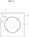
- the size of the receiving unit 21 is adjustable. When passing through the lower penetrated part 210, the size of the receiving unit 21 may be smaller than the diameter of the lower penetrated part 210 so that the receiving unit 21 may easily pass through the lower penetrated part 210. Further, when being disposed inside the biodegradable concrete 200, the size of the receiving unit 21 is expanded so that the receiving unit 21 may receive most of the radioactive waste 1 and may be smaller than the interior diameter of the biodegradable concrete 200.
- This waste receiving device 20 is movable through the lower penetrated part 210 of the biodegradable concrete 200.
- the lower penetrated part 210 of the biodegradable concrete 200 may be connected to the interior of the biodegradable concrete 200 where the decontamination device 10 is positioned.
- the waste receiving device 20 may be disposed under the decontamination device 10. Therefore, the waste receiving device 20 may easily accommodate the radioactive waste 1 separated from the inner wall of the biodegradable concrete 200 by the decontamination device 10.
- the waste receiving device 20 may be easily inserted and taken out from time to time by using the lower penetrated part 210 of the biodegradable concrete 200 without the need to take out the radioactive waste 1 of the inner wall of the biodegradable concrete 200 to an upper opening 220. Therefore, it is possible to shorten the decontamination process time of the inner wall of the biodegradable concrete 200.
- the dust blocking device 30 may block the upper opening 220 of the biodegradable concrete 200 to block the outflow of the radioactive dust 3.
- the dust blocking device 30 may include a tent or a shield.
- the tent or shield has been described as an example of the dust blocking device 30, but it is not limited thereto, and various devices for blocking the radioactive dust are possible.
- the dust blocking device 30 may further include a blocking adjusting unit for blocking or opening the upper opening 220 of the biodegradable concrete 200.
- the upper opening 220 of the biodegradable concrete 200 is kept sealed by using the dust blocking device 30, thereby reducing worker exposure to the radioactive dust 3 and preventing the spread of the radioactive dust.
- the dust collecting device 40 is connected to the dust blocking device 30 and is disposed outside the biodegradable concrete 200. It is possible to secure a view inside the work part through the dust collecting device 40 using an exhaust fan.
- FIG. 2 is a top plan view showing a state in which a size of a receiving unit of a waste receiving device of FIG. 1 is changed inside biodegradable concrete
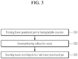
- FIG. 3 is a flowchart of a decontamination and dismantling method of biodegradable concrete of a nuclear power plant according to an exemplary embodiment.
- the in-core instrument 300 installed under the biodegradable concrete 200 is dismantled by using the dismantling device 5 to form the lower penetrated part 210 under the biodegradable concrete 200 (S10). Since the in-core instrument 300 is connected to the nuclear reactor 100 through a plurality of cables, etc., the cables may be separated from the nuclear reactor 100 to physically separate the in-core instrument 300 from the nuclear reactor 100.
- the nuclear reactor 100 disposed inside the biodegradable concrete 200 is also dismantled by using a nuclear reactor dismantling device 6.
- the decontamination device 10 is inserted inside the biodegradable concrete 200 to decontaminate the radioactive waste 1 of the inner wall of the biodegradable concrete 200 (S20). Further, the waste receiving device 20 is inserted into the interior of the biodegradable concrete 200 through the lower penetrated part 210 of the biodegradable concrete 200 (S30). At this time, the lower penetrated part 210 of the biodegradable concrete 200 may be connected to the interior of the biodegradable concrete 200. Thus, the waste receiving device 20 may be disposed under the decontamination device 10. Therefore, the waste receiving device 20 may easily accommodate the radioactive waste 1 of the inner wall of the biodegradable concrete 200 generated by the decontamination device 10.
- the upper opening 220 of the biodegradable concrete 200 is blocked using the dust blocking device 30 to block the outflow of the radioactive dust 3.
- the radioactive dust 3 may be collected using the dust collecting device 40 connected to the dust blocking device 30.
- the waste receiving device 20 may be easily input and taken out from time to time by using the lower penetrated part 210 of the biodegradable concrete 200 without the need to carry out the radioactive waste 1 of the inner wall of the biodegradable concrete 200 to the upper opening 220 of the biodegradable concrete 200, the decontamination and dismantling process time of the inner wall of the biodegradable concrete 200 may be shortened.
Landscapes
- Engineering & Computer Science (AREA)
- Physics & Mathematics (AREA)
- General Engineering & Computer Science (AREA)
- High Energy & Nuclear Physics (AREA)
- Plasma & Fusion (AREA)
- Life Sciences & Earth Sciences (AREA)
- Food Science & Technology (AREA)
- Chemical & Material Sciences (AREA)
- Inorganic Chemistry (AREA)
- Working Measures On Existing Buildindgs (AREA)
Abstract
Description
- The present disclosure relates to a dismantling and decontamination system and method of biodegradable concrete of a nuclear power plant. More particularly, the present invention relates to a dismantling and decontamination system and method of biodegradable concrete of a PWR type of nuclear power plant.
- As fossil energy is depleted worldwide, nuclear power generation is being used as a major energy source. In such nuclear power generation, a generally-used pressurized water reactor (PWR) nuclear power plant consists of a primary system circulating in a nuclear reactor, a secondary system circulating in a steam generator, and a tertiary system circulating in a condenser. Specifically, in the primary system, a pressure is applied to a coolant contained in a reactor to maintain 150 atm and 300 °C, and in the secondary system, the coolant boils water on the side of the steam generator while passing through the steam generator to generate steam to turn a turbine. In the tertiary system, the steam generated for turning the turbine passes through a condenser, becomes water again, and is sent to the steam generator.
- The nuclear reactor of such a PWR type of nuclear power plant includes an external pressure vessel, and a nuclear reactor vessel composed of a core barrel that is formed with a smaller diameter than that of the pressure vessel and installed at the center of the pressure vessel. Inside the core barrel, the core into which a nuclear fuel rod is loaded is positioned, and a precipitation unit, which is a space of a ring shape due to the difference in diameter, is formed between the core barrel and the pressure vessel. In addition, a plurality of low temperature tubes that are connected to the pressure vessel and become circulation passages of cooling water, and a high temperature tube (hot leg) connected to the core barrel so that the cooling water heated while inflowing through the low temperature tubes and passing through the precipitation unit and the core flows toward the steam generator, are included.
- In this PWR type of nuclear power plant, biodegradable concrete is installed as a reinforced concrete structure to protect against radiation exposure of workers by supporting the nuclear reactor and shielding neutrons.
- The biodegradable concrete forms a large cylindrical reinforced concrete structure by stacking a plurality of layers and is highly radioactive by irradiation of neutrons, so if workers work in close proximity thereto, there is a risk of radiation exposure. Particularly, since the inner wall of the biodegradable concrete is severely contaminated with a radioactive material, when dismantling a pressurized light water reactor (PWR) type of nuclear power plant that has expired and is permanently stopped, a decontamination process of the inner wall of the biodegradable concrete is required.
- However, for the decontamination process, if a worker forms a separate through-hole for inserting the decontamination device into the biodegradable concrete, there is a concern of radioactive exposure and movement of radioactive dust.
- The present exemplary embodiment relates to a dismantling and decontamination system and method of biodegradable concrete of a nuclear power plant that may shorten the dismantling process time and a worker exposure.
- A dismantling and decontamination system of biodegradable concrete of a nuclear power plant according to an exemplary embodiment includes: a dismantling device for dismantling an in-core instrument installed under biodegradable concrete to form a lower penetrated part of the biodegradable concrete; a decontamination device inserted inside the biodegradable concrete for decontaminating radioactive waste of the inner wall of the biodegradable concrete; a waste receiving device movable through the lower penetrated part of the biodegradable concrete; and a blocking device for blocking the upper opening of the biodegradable concrete to block an outflow of the radioactive dust.
- A dust collecting device connected to the dust blocking device and collecting the radioactive dust may be further included.
- The waste receiving device may include: a receiving unit receiving radioactive waste; a receiving unit size adjusting unit for adjusting the size of the receiving unit; and a moving unit for moving the receiving unit.
- In the lower penetrated part, the size of the receiving unit may be smaller than the diameter of the lower penetrated part, and in the biodegradable concrete, the size of the receiving unit may be smaller than the interior diameter of the biodegradable concrete.
- The lower penetrated part of the biodegradable concrete may be connected to the interior of the biodegradable concrete.
- The decontamination device may include an inner wall hammer or a scabbier.
- The dust blocking device may include a tent or a shield.
- A decontamination and dismantling method of biodegradable concrete of a nuclear power plant according to an exemplary embodiment includes: dismantling an in-core instrument installed under the biodegradable concrete by using a dismantling device to form a lower penetrated part of the biodegradable concrete; inserting a decontamination device inside the biodegradable concrete to decontaminate radioactive waste of the inner wall of the biodegradable concrete; and inserting the waste receiving device through the lower penetrated part of the biodegradable concrete inside the biodegradable concrete.
- Blocking the upper opening of the biodegradable concrete by using a dust blocking device to block outflow of the radioactive dust may be further included.
- Collecting the radioactive dust by using a dust collecting device connected to the dust blocking device may be further included.
- The lower penetrated part of the biodegradable concrete may be connected to the interior of the biodegradable concrete.
- Dismantling a nuclear reactor installed inside the biodegradable concrete before decontaminating the radioactive waste of the inner wall of the biodegradable concrete may be further included.
- According to an exemplary embodiment, during the decontamination and dismantling process of the biodegradable concrete of the nuclear power plant, the dismantling process time may be shortened by frequently inputting and drawing out the radioactive waste by using the lower penetrated part of the biodegradable concrete where the dismantled in-core instrument was disposed without taking out the radioactive waste to the upper opening of the biodegradable concrete, thereby efficiently carrying out the decontamination and dismantling process of the biodegradable concrete inner wall.
- In addition, since the decontamination process of the biodegradable concrete inner wall is performed using the lower penetrated part of the biodegradable concrete, the exposure of workers to the radioactive dust may be reduced by maintaining the sealing of the upper part of the biodegradable concrete.
-
-
FIG. 1 is a schematic diagram of a dismantling and decontamination system of biodegradable concrete of a nuclear power plant according to an exemplary embodiment. -
FIG. 2 is a top plan view showing a state in which a size of a receiving unit of a waste receiving device ofFIG. 1 is changed inside biodegradable concrete. -
FIG. 3 is a flowchart of a decontamination and dismantling method of biodegradable concrete of a nuclear power plant according to an exemplary embodiment. -
FIG. 4 is a view showing a step before dismantling biodegradable concrete of a nuclear power plant according to an exemplary embodiment. - The present invention will be described more fully hereinafter with reference to the accompanying drawings, in which exemplary embodiments of the invention are shown. As those skilled in the art would realize, the described embodiments may be modified in various different ways, all without departing from the scope of the present invention.
- In order to clearly explain the present invention, portions that are not directly related to the present invention are omitted, and the same reference numerals are attached to the same or similar constituent elements through the entire specification.
- In addition, the size and thickness of each configuration shown in the drawings are arbitrarily shown for better understanding and ease of description, but the present invention is not limited thereto.
- In the drawings, the thickness of layers, films, panels, regions, etc., are exaggerated for clarity. In the drawings, for better understanding and ease of description, the thicknesses of some layers and areas are exaggerated. It will be understood that when an element such as a layer, film, region, or substrate is referred to as being "on" another element, it can be directly on the other element or intervening elements may also be present.
- In addition, unless explicitly described to the contrary, the word "comprise", and variations such as "comprises" or "comprising", will be understood to imply the inclusion of stated elements but not the exclusion of any other elements. Further, in the specification, the word "on" means positioning on or below the object portion, but does not essentially mean positioning on the upper side of the object portion based on a gravity direction.
-
FIG. 1 is a schematic diagram of a dismantling and decontamination system of biodegradable concrete of a nuclear power plant according to an exemplary embodiment. - As shown in
FIG. 1 , a dismantling and decontamination system of biodegradable concrete of a nuclear power plant according to an exemplary embodiment includes adismantling device 5 dismantling an in-core instrument (ICI) 300 installed underbiodegradable concrete 200, adecontamination device 10 decontaminatingradioactive waste 1 of the inner wall of thebiodegradable concrete 200, awaste receiving device 20 receiving theradioactive waste 1 decontaminated by thedecontamination device 10, adust blocking device 30 blockingradioactive dust 3 generated during the decontamination of theradioactive waste 1, and adust collecting device 40 collecting theradioactive dust 3. - The
dismantling device 5 forms a lowerpenetrated part 210 under thebiodegradable concrete 200 by dismantling the in-core instrument 300 installed from the lower part of thebiodegradable concrete 200 to the inside of anuclear reactor 100. The lowerpenetrated part 210 of thebiodegradable concrete 200 is the space where the in-core instrument (ICI) 300 of thebiodegradable concrete 200 was positioned. The in-core instrument 300 is a device to measure an output distribution and combustibility of a nuclear fuel inside the nuclear reactor and to measure an outlet temperature of the core of thenuclear reactor 100 by detecting neutrons generated during the nuclear fission reaction process of thenuclear reactor 100. - The
decontamination device 10 is put into the inside of thebiodegradable concrete 200. Thedecontamination device 10 may include an inner wall hammer or a scabbier. The inner wall hammer hits the inner wall of thebiodegradable concrete 200 to remove theradioactive waste 1 from the inner wall of thebiodegradable concrete 200. Further, the scabbler scrapes the inner wall of thebiodegradable concrete 200 to remove theradioactive waste 1 from the inner wall of thebiodegradable concrete 200. In the present exemplary embodiment, the inner wall hammer or the scabbler has been described as an example of the decontamination device, but it is not limited thereto, and various devices are possible as long as it is a device for removing theradioactive waste 1 from the inner wall of thebiodegradable concrete 200. - The
waste receiving device 20 may include areceiving unit 21 for receiving theradioactive waste 1, a receiving unitsize adjusting unit 22 for adjusting the size of thereceiving unit 21 and a movingunit 23 for moving thereceiving unit 21. - As shown in
FIG. 2 , the size of thereceiving unit 21 is adjustable. When passing through the lowerpenetrated part 210, the size of thereceiving unit 21 may be smaller than the diameter of the lowerpenetrated part 210 so that thereceiving unit 21 may easily pass through the lowerpenetrated part 210. Further, when being disposed inside thebiodegradable concrete 200, the size of the receivingunit 21 is expanded so that thereceiving unit 21 may receive most of theradioactive waste 1 and may be smaller than the interior diameter of thebiodegradable concrete 200. - This
waste receiving device 20 is movable through the lowerpenetrated part 210 of thebiodegradable concrete 200. The lowerpenetrated part 210 of thebiodegradable concrete 200 may be connected to the interior of thebiodegradable concrete 200 where thedecontamination device 10 is positioned. Thus, the waste receivingdevice 20 may be disposed under thedecontamination device 10. Therefore, thewaste receiving device 20 may easily accommodate theradioactive waste 1 separated from the inner wall of thebiodegradable concrete 200 by thedecontamination device 10. - As described above, when the decontamination process of the
biodegradable concrete 200 of the nuclear power plant is in progress, thewaste receiving device 20 may be easily inserted and taken out from time to time by using the lower penetratedpart 210 of thebiodegradable concrete 200 without the need to take out theradioactive waste 1 of the inner wall of thebiodegradable concrete 200 to anupper opening 220. Therefore, it is possible to shorten the decontamination process time of the inner wall of thebiodegradable concrete 200. - The
dust blocking device 30 may block theupper opening 220 of thebiodegradable concrete 200 to block the outflow of theradioactive dust 3. Thedust blocking device 30 may include a tent or a shield. In the present exemplary embodiment, the tent or shield has been described as an example of thedust blocking device 30, but it is not limited thereto, and various devices for blocking the radioactive dust are possible. In addition, thedust blocking device 30 may further include a blocking adjusting unit for blocking or opening theupper opening 220 of thebiodegradable concrete 200. - In this way, when the decontamination and dismantling process of the inner wall of the
biodegradable concrete 200 is performed using the lower penetratedpart 210 of thebiodegradable concrete 200, theupper opening 220 of thebiodegradable concrete 200 is kept sealed by using thedust blocking device 30, thereby reducing worker exposure to theradioactive dust 3 and preventing the spread of the radioactive dust. - The
dust collecting device 40 is connected to thedust blocking device 30 and is disposed outside thebiodegradable concrete 200. It is possible to secure a view inside the work part through thedust collecting device 40 using an exhaust fan. - Meanwhile, the decontamination and dismantling method of the biodegradable concrete of the nuclear power plant according to an exemplary embodiment of the present invention is described in detail below with reference to drawings.
-
FIG. 2 is a top plan view showing a state in which a size of a receiving unit of a waste receiving device ofFIG. 1 is changed inside biodegradable concrete, andFIG. 3 is a flowchart of a decontamination and dismantling method of biodegradable concrete of a nuclear power plant according to an exemplary embodiment. - As shown in
FIG. 3 andFIG. 4 , in the decontamination and dismantling method of the biodegradable concrete of the nuclear power plant according to an exemplary embodiment of the present invention, the in-core instrument 300 installed under thebiodegradable concrete 200 is dismantled by using thedismantling device 5 to form the lower penetratedpart 210 under the biodegradable concrete 200 (S10). Since the in-core instrument 300 is connected to thenuclear reactor 100 through a plurality of cables, etc., the cables may be separated from thenuclear reactor 100 to physically separate the in-core instrument 300 from thenuclear reactor 100. - At this time, the
nuclear reactor 100 disposed inside thebiodegradable concrete 200 is also dismantled by using a nuclear reactor dismantling device 6. - Next, as shown in
FIG. 1 andFIG. 3 , thedecontamination device 10 is inserted inside thebiodegradable concrete 200 to decontaminate theradioactive waste 1 of the inner wall of the biodegradable concrete 200 (S20). Further, thewaste receiving device 20 is inserted into the interior of thebiodegradable concrete 200 through the lower penetratedpart 210 of the biodegradable concrete 200 (S30). At this time, the lower penetratedpart 210 of thebiodegradable concrete 200 may be connected to the interior of thebiodegradable concrete 200. Thus, thewaste receiving device 20 may be disposed under thedecontamination device 10. Therefore, thewaste receiving device 20 may easily accommodate theradioactive waste 1 of the inner wall of thebiodegradable concrete 200 generated by thedecontamination device 10. - In addition, as shown in
FIG. 1 , theupper opening 220 of thebiodegradable concrete 200 is blocked using thedust blocking device 30 to block the outflow of theradioactive dust 3. At this time, theradioactive dust 3 may be collected using thedust collecting device 40 connected to thedust blocking device 30. - As described above, when the decontamination process of
biodegradable concrete 200 of the nuclear power plant is in progress, since thewaste receiving device 20 may be easily input and taken out from time to time by using the lower penetratedpart 210 of thebiodegradable concrete 200 without the need to carry out theradioactive waste 1 of the inner wall of thebiodegradable concrete 200 to theupper opening 220 of thebiodegradable concrete 200, the decontamination and dismantling process time of the inner wall of thebiodegradable concrete 200 may be shortened. - While this invention has been described in connection with what is presently considered to be practical exemplary embodiments, it is to be understood that the invention is not limited to the disclosed embodiments. On the contrary, it is intended to cover various modifications and equivalent arrangements included within the scope of the appended claims.
Claims (12)
- A dismantling and decontamination system of biodegradable concrete of a nuclear power plant, comprising:a dismantling device for dismantling an in-core instrument installed under biodegradable concrete to form a lower penetrated part of the biodegradable concrete;a decontamination device inserted inside the biodegradable concrete for decontaminating radioactive waste of the inner wall of the biodegradable concrete;a waste receiving device movable through the lower penetrated part of the biodegradable concrete; anda blocking device for blocking the upper opening of the biodegradable concrete to block an outflow of the radioactive dust.
- The dismantling and decontamination system of the biodegradable concrete of the nuclear power plant of claim 1, further comprising
a dust collecting device connected to the dust blocking device and collecting the radioactive dust. - The dismantling and decontamination system of the biodegradable concrete of the nuclear power plant of claim 2, wherein
the waste receiving device includes:a receiving unit receiving radioactive waste;a receiving unit size adjusting unit for adjusting the size of the receiving unit; anda moving unit for moving the receiving unit. - The dismantling and decontamination system of the biodegradable concrete of the nuclear power plant of claim 3, wherein
in the lower penetrated part, the size of the receiving unit is smaller than the diameter of the lower penetrated part, and in the biodegradable concrete, the size of the receiving unit is smaller than the interior diameter of the biodegradable concrete. - The dismantling and decontamination system of the biodegradable concrete of the nuclear power plant of claim 2, wherein
the lower penetrated part of the biodegradable concrete is connected to the interior of the biodegradable concrete. - The dismantling and decontamination system of the biodegradable concrete of the nuclear power plant of claim 2, wherein
the decontamination device includes an inner wall hammer or a scabbier. - The dismantling and decontamination system of the biodegradable concrete of the nuclear power plant of claim 2, wherein
the dust blocking device includes a tent or a shield. - A decontamination and dismantling method of biodegradable concrete of a nuclear power plant, comprising:dismantling an in-core instrument installed under the biodegradable concrete by using a dismantling device to form a lower penetrated part of the biodegradable concrete;inserting a decontamination device inside the biodegradable concrete to decontaminate radioactive waste of the inner wall of the biodegradable concrete; andinserting the waste receiving device through the lower penetrated part of the biodegradable concrete inside the biodegradable concrete.
- The decontamination and dismantling method of biodegradable concrete of the nuclear power plant of claim 8, further comprising
blocking the upper opening of the biodegradable concrete by using a dust blocking device to block outflow of the radioactive dust. - The decontamination and dismantling method of biodegradable concrete of the nuclear power plant of claim 9, further comprising
collecting the radioactive dust by using a dust collecting device connected to the dust blocking device. - The decontamination and dismantling method of biodegradable concrete of the nuclear power plant of claim 8, wherein
the lower penetrated part of the biodegradable concrete is connected to the interior of the biodegradable concrete. - The decontamination and dismantling method of biodegradable concrete of the nuclear power plant of claim 8, further comprising
dismantling a nuclear reactor installed inside the biodegradable concrete before decontaminating the radioactive waste of the inner wall of the biodegradable concrete.
Applications Claiming Priority (2)
| Application Number | Priority Date | Filing Date | Title |
|---|---|---|---|
| KR1020180044584A KR102061287B1 (en) | 2018-04-17 | 2018-04-17 | Dismantling and decontamination system and method of biodegradable concrete of pwr type nuclear power plant |
| PCT/KR2019/004660 WO2019203577A1 (en) | 2018-04-17 | 2019-04-17 | System and method for dismantling and decontaminating bio-protective concrete of pressurized water reactor type nuclear power plant |
Publications (2)
| Publication Number | Publication Date |
|---|---|
| EP3783621A1 true EP3783621A1 (en) | 2021-02-24 |
| EP3783621A4 EP3783621A4 (en) | 2022-01-12 |
Family
ID=68239764
Family Applications (1)
| Application Number | Title | Priority Date | Filing Date |
|---|---|---|---|
| EP19787623.8A Pending EP3783621A4 (en) | 2018-04-17 | 2019-04-17 | SYSTEM AND METHOD FOR DISMANTLING AND DECONTAMINATING BIOPROTECTIVE CONCRETE OF A NUCLEAR POWER PLANT OF THE PRESSURIZED WATER REACTOR TYPE |
Country Status (5)
| Country | Link |
|---|---|
| US (2) | US12437892B2 (en) |
| EP (1) | EP3783621A4 (en) |
| JP (1) | JP7052077B2 (en) |
| KR (1) | KR102061287B1 (en) |
| WO (1) | WO2019203577A1 (en) |
Families Citing this family (2)
| Publication number | Priority date | Publication date | Assignee | Title |
|---|---|---|---|---|
| KR101942997B1 (en) * | 2018-07-27 | 2019-01-28 | 한국원자력연구원 | Method for removal of radioactivation structure in nuclear power plant |
| KR102942209B1 (en) * | 2023-09-25 | 2026-03-19 | 한국수력원자력 주식회사 | Process for disposing of a composite structure containing radioactive waste |
Family Cites Families (14)
| Publication number | Priority date | Publication date | Assignee | Title |
|---|---|---|---|---|
| US2935616A (en) * | 1955-02-14 | 1960-05-03 | Farrel Birmingham Co Inc | Radiation shielding container |
| JPS5923298A (en) * | 1982-07-30 | 1984-02-06 | 清水建設株式会社 | Method of cutting pipe of reactor |
| DE3337549A1 (en) * | 1983-10-15 | 1985-04-25 | Kernforschungszentrum Karlsruhe Gmbh, 7500 Karlsruhe | Method of preventing dust entrainment during the comminution of solid-material structures and apparatus for carrying out the method |
| GB8721673D0 (en) * | 1987-09-15 | 1987-10-21 | Macdonald Pneumatic Tools | Apparatus for scabbling concrete |
| US5001870A (en) * | 1987-10-05 | 1991-03-26 | Kajima Corporation | Method of cutting and disassembling cylindrical structure |
| US4969311A (en) * | 1987-10-30 | 1990-11-13 | Nutter Victor H | Collecting and packaging hazardous particulate materials |
| JP2857805B2 (en) | 1990-10-22 | 1999-02-17 | 株式会社竹中工務店 | Large Blocking Cutting Method of Activated Part in Reactor Biological Shield Structure |
| JP3597570B2 (en) * | 1994-09-07 | 2004-12-08 | 東芝プラントシステム株式会社 | Reactor dismantling method and apparatus |
| JP2987070B2 (en) * | 1995-03-02 | 1999-12-06 | 株式会社日立製作所 | Method of cutting the structure inside the reactor pressure vessel |
| KR100391179B1 (en) | 2000-08-02 | 2003-07-12 | 한국전력공사 | Teleoperated mobile cleanup device for highly radioactive fine waste |
| DE102009002681A1 (en) * | 2009-02-18 | 2010-09-09 | Areva Np Gmbh | Method for the decontamination of radioactively contaminated surfaces |
| US8873696B2 (en) * | 2010-03-27 | 2014-10-28 | Special Applications Technology, Inc. | Systems and methods for dismantling a nuclear reactor |
| US9302294B2 (en) * | 2013-08-02 | 2016-04-05 | Babcock Noell Gmbh | Separating radioactive contaminated materials from cleared materials resulting from decommissioning a power plant |
| JP6440030B2 (en) | 2015-03-04 | 2018-12-19 | 株式会社Ihi | Demolition collection method and dismantling collection equipment for in-furnace structures |
-
2018
- 2018-04-17 KR KR1020180044584A patent/KR102061287B1/en active Active
-
2019
- 2019-04-17 JP JP2020557251A patent/JP7052077B2/en active Active
- 2019-04-17 US US17/048,222 patent/US12437892B2/en active Active
- 2019-04-17 EP EP19787623.8A patent/EP3783621A4/en active Pending
- 2019-04-17 WO PCT/KR2019/004660 patent/WO2019203577A1/en not_active Ceased
-
2025
- 2025-08-04 US US19/289,239 patent/US20250364149A1/en active Pending
Also Published As
| Publication number | Publication date |
|---|---|
| US12437892B2 (en) | 2025-10-07 |
| KR20190121081A (en) | 2019-10-25 |
| US20210174978A1 (en) | 2021-06-10 |
| WO2019203577A1 (en) | 2019-10-24 |
| JP7052077B2 (en) | 2022-04-11 |
| KR102061287B1 (en) | 2019-12-31 |
| US20250364149A1 (en) | 2025-11-27 |
| JP2021518913A (en) | 2021-08-05 |
| EP3783621A4 (en) | 2022-01-12 |
Similar Documents
| Publication | Publication Date | Title |
|---|---|---|
| US20250364149A1 (en) | Dismantling and decontamination system and method of bioprotective concrete of pwr type nuclear power plant | |
| Alemberti et al. | European lead fast reactor—ELSY | |
| US11715573B2 (en) | Decommissioning method of biodegradable concrete of PWR type nuclear power plant | |
| Guidez et al. | New reactor safety measures for the european sodium fast reactor—part i: Conceptual design | |
| US5084234A (en) | Absorption casing for a source of radioactive radiation, particularly for a nuclear reactor | |
| KR102035852B1 (en) | Decommissioning method of biodegradable concrete of pwr type nuclear power plant | |
| Hiwatari et al. | Development of plant concept related to tritium handling in the water-cooling system for JA DEMO | |
| KR102092373B1 (en) | Method for decommissioning nuclear facilities | |
| Rahman et al. | Innovative and conventional cementitious systems in nuclear industry—Safety aspect | |
| Guidez et al. | Safety | |
| Burclová et al. | Nuclear Regulatory Authority Requirements-First Phase of NPP A1 Decommissioning | |
| Kumar et al. | Equipment Qualification Program Under Accident Conditions for KAPP-3&4 Indian Pressurized Heavy Water Reactors | |
| Cheng et al. | Development and Application of High Temperature and Radiation Protection Equipment for Spent Fuel Dry Storage System | |
| RACIMOR et al. | Lessons Learned From A Periodic Safety Review, Applied To The Design Of New Nuclear Fuel Cycle Facilities | |
| Lee et al. | Decommissioning Design of Spent Fuel Pool Cooling and Cleanup System | |
| Kishimoto et al. | Decommissioning activity of phase 2 in JRR-2 | |
| JP2020076621A (en) | Equipment processing method of nuclear power plant | |
| Blaumann et al. | Key Technical and Safety Requirements for a new Research Reactor: The RA-10 Reactor Experience | |
| Bartels | Safety design for ITER and fusion power reactors | |
| Kishimoto et al. | Decommissioning program of JRR-2 | |
| Topf | Full System Decontamination (FSD) with the CORDR Family prior to Decommissioning-Experiences at the German NPP Obrigheim 2007 | |
| Kishimoto et al. | Decommissioning plan and current status of JRR-2 | |
| Wu | Neutronics Design of Fusion Experimental Reactors | |
| Frost et al. | Design considerations for water pool storage of irradiated CANDU fuel by Ontario Hydro | |
| Chuang et al. | Simplification of the severe accident management guideline for the containment flooding in a Mark-III containment |
Legal Events
| Date | Code | Title | Description |
|---|---|---|---|
| STAA | Information on the status of an ep patent application or granted ep patent |
Free format text: STATUS: THE INTERNATIONAL PUBLICATION HAS BEEN MADE |
|
| PUAI | Public reference made under article 153(3) epc to a published international application that has entered the european phase |
Free format text: ORIGINAL CODE: 0009012 |
|
| STAA | Information on the status of an ep patent application or granted ep patent |
Free format text: STATUS: REQUEST FOR EXAMINATION WAS MADE |
|
| 17P | Request for examination filed |
Effective date: 20201112 |
|
| AK | Designated contracting states |
Kind code of ref document: A1 Designated state(s): AL AT BE BG CH CY CZ DE DK EE ES FI FR GB GR HR HU IE IS IT LI LT LU LV MC MK MT NL NO PL PT RO RS SE SI SK SM TR |
|
| AX | Request for extension of the european patent |
Extension state: BA ME |
|
| DAV | Request for validation of the european patent (deleted) | ||
| DAX | Request for extension of the european patent (deleted) | ||
| A4 | Supplementary search report drawn up and despatched |
Effective date: 20211215 |
|
| RIC1 | Information provided on ipc code assigned before grant |
Ipc: G21F 9/30 20060101ALI20211209BHEP Ipc: G21F 9/00 20060101ALI20211209BHEP Ipc: G21D 1/00 20060101AFI20211209BHEP |
|
| STAA | Information on the status of an ep patent application or granted ep patent |
Free format text: STATUS: EXAMINATION IS IN PROGRESS |
|
| 17Q | First examination report despatched |
Effective date: 20240909 |