EP3783527A1 - Method and device for identifying object node in image, terminal and computer readable storage medium - Google Patents
Method and device for identifying object node in image, terminal and computer readable storage medium Download PDFInfo
- Publication number
- EP3783527A1 EP3783527A1 EP19787687.3A EP19787687A EP3783527A1 EP 3783527 A1 EP3783527 A1 EP 3783527A1 EP 19787687 A EP19787687 A EP 19787687A EP 3783527 A1 EP3783527 A1 EP 3783527A1
- Authority
- EP
- European Patent Office
- Prior art keywords
- image
- feature
- region
- node
- target image
- Prior art date
- Legal status (The legal status is an assumption and is not a legal conclusion. Google has not performed a legal analysis and makes no representation as to the accuracy of the status listed.)
- Granted
Links
Images





Classifications
-
- G—PHYSICS
- G06—COMPUTING OR CALCULATING; COUNTING
- G06V—IMAGE OR VIDEO RECOGNITION OR UNDERSTANDING
- G06V40/00—Recognition of biometric, human-related or animal-related patterns in image or video data
- G06V40/10—Human or animal bodies, e.g. vehicle occupants or pedestrians; Body parts, e.g. hands
- G06V40/107—Static hand or arm
-
- G—PHYSICS
- G06—COMPUTING OR CALCULATING; COUNTING
- G06V—IMAGE OR VIDEO RECOGNITION OR UNDERSTANDING
- G06V10/00—Arrangements for image or video recognition or understanding
- G06V10/70—Arrangements for image or video recognition or understanding using pattern recognition or machine learning
- G06V10/764—Arrangements for image or video recognition or understanding using pattern recognition or machine learning using classification, e.g. of video objects
-
- G—PHYSICS
- G06—COMPUTING OR CALCULATING; COUNTING
- G06F—ELECTRIC DIGITAL DATA PROCESSING
- G06F18/00—Pattern recognition
- G06F18/20—Analysing
- G06F18/25—Fusion techniques
- G06F18/253—Fusion techniques of extracted features
-
- G—PHYSICS
- G06—COMPUTING OR CALCULATING; COUNTING
- G06V—IMAGE OR VIDEO RECOGNITION OR UNDERSTANDING
- G06V10/00—Arrangements for image or video recognition or understanding
- G06V10/70—Arrangements for image or video recognition or understanding using pattern recognition or machine learning
- G06V10/82—Arrangements for image or video recognition or understanding using pattern recognition or machine learning using neural networks
-
- G—PHYSICS
- G06—COMPUTING OR CALCULATING; COUNTING
- G06V—IMAGE OR VIDEO RECOGNITION OR UNDERSTANDING
- G06V40/00—Recognition of biometric, human-related or animal-related patterns in image or video data
- G06V40/20—Movements or behaviour, e.g. gesture recognition
- G06V40/28—Recognition of hand or arm movements, e.g. recognition of deaf sign language
-
- G—PHYSICS
- G06—COMPUTING OR CALCULATING; COUNTING
- G06V—IMAGE OR VIDEO RECOGNITION OR UNDERSTANDING
- G06V2201/00—Indexing scheme relating to image or video recognition or understanding
- G06V2201/07—Target detection
Definitions
- the upsampling processes and the sets of deconvolution calculation processes may be performed alternately, and after completion of each upsampling process, a feature fusion process is performed on an image feature obtained by the upsampling process and corresponding downsampled image feature that has the same resolution as the image feature, to obtain a fused image feature. Then, deconvolution calculation processing is performed on the fused image feature.
- the N-th feature fusion process is fusing an image feature obtained by the N-th upsampling process with the first image feature
- the target image feature is an image feature obtained by the M-th sets of deconvolution calculation processes. Deconvolution calculation is performed on the target image feature, to obtain the region probability matrix.
- downsampling processing and/or convolution calculation processing may be performed on the first node recognition feature, to obtain an intermediate node recognition feature.
- Node information prediction processing is performed on the intermediate node recognition feature, to obtain the second node recognition feature.
- a set of convolution calculation processing may be performed on the intermediate node recognition feature, to obtain a probability matrix. The probability matrix, together with a loss function, may be used for optimizing parameters of the node recognition model in the process of optimizing the node recognition model.
- other intermediate node recognition features may be obtained, and at least two intermediate node recognition features may be selected for feature fusion, to obtain the second node recognition feature.
- the detection unit 302 may be specifically configured to: invoke a preset first region detection model to perform image feature recognition on the original image, to obtain a region probability matrix, an element value A uv in the region probability matrix representing a probability that a corresponding pixel point O uv in the original image belongs to the target image region, u representing a row number, and v representing a column number; perform binarization processing on the region probability matrix by using a preset threshold, to obtain a feature element value region; and determine the target image region according to the feature element value region.
- a subimage including a target image object is inputted by the recognition unit 304 to a preset node recognition network for node recognition, to avoid the problem of inaccurate node recognition in a case that a target image region occupies a small proportion of area of the original image, thereby improving the recognition precision and meeting the requirement of elaborate hand gesture recognition.
Landscapes
- Engineering & Computer Science (AREA)
- Theoretical Computer Science (AREA)
- Physics & Mathematics (AREA)
- General Physics & Mathematics (AREA)
- Computer Vision & Pattern Recognition (AREA)
- Evolutionary Computation (AREA)
- Multimedia (AREA)
- General Health & Medical Sciences (AREA)
- Health & Medical Sciences (AREA)
- Artificial Intelligence (AREA)
- Software Systems (AREA)
- Data Mining & Analysis (AREA)
- Computing Systems (AREA)
- Databases & Information Systems (AREA)
- Medical Informatics (AREA)
- Human Computer Interaction (AREA)
- Social Psychology (AREA)
- Psychiatry (AREA)
- Life Sciences & Earth Sciences (AREA)
- Bioinformatics & Cheminformatics (AREA)
- Bioinformatics & Computational Biology (AREA)
- Evolutionary Biology (AREA)
- General Engineering & Computer Science (AREA)
- Image Analysis (AREA)
Abstract
Description
- This application claims priority to Chinese Patent Application No.
2018103460293 - The present disclosure relates to the field of information processing technologies, and in particular, to a method and an apparatus for recognizing an object node in an image, a terminal, and a computer-readable storage medium.
- With the popularization of the concept of Artificial Intelligence (AI), image recognition has become a popular research topic. The so-called image recognition, as an important field of AI, is a technology for processing, analyzing and understanding an image by using a computer, to recognize targets and objects in different modes. The objects in the image may refer to a text, an item, a gesture, and the like. How to better recognize an image object becomes a research focus.
- According to embodiments of the present disclosure, a method and an apparatus for recognizing an object node in an image, a terminal, and a computer-readable storage medium are provided.
- A method for recognizing an object node in an image, executed by a computer device, includes:
- obtaining a to-be-recognized original image, the original image including a target image object;
- performing image detection on the original image, to determine a target image region in the original image, the target image region including the target image object;
- performing image cropping on the original image according to the target image region, to obtain a subimage including the target image object; and
- invoking a preset node recognition model to perform node recognition on the subimage, to obtain node recognition information of the target image object.
- An apparatus for recognizing an object node in an image includes:
- an obtaining unit, configured to obtain a to-be-recognized original image, the original image including a target image object;
- a detection unit, configured to perform image detection on the original image, to determine a target image region in the original image, the target object region including the target image object;
- a cropping unit, configured to perform image cropping on the original image according to the target image region, to obtain a subimage including the target image object; and
- a recognition unit, configured to invoke a preset node recognition model to perform node recognition on the subimage, to obtain node recognition information of the target image object.
- An intelligent terminal includes a processor and a memory, the memory storing a computer-readable instruction, the computer-readable instruction, when executed by the processor, causing the processor to perform the following operations:
- obtaining a to-be-recognized original image, the original image including a target image object;
- performing image detection on the original image, to determine a target image region in the original image, the target image region including the target image object;
- performing image cropping on the original image according to the target image region, to obtain a subimage including the target image object; and
- invoking a preset node recognition model to perform node recognition on the subimage, to obtain node recognition information of the target image object.
- A computer-readable storage medium stores a computer program instruction, the computer program instruction, when executed, being used for implementing the foregoing method for recognizing an object node in an image.
- Details of one or more embodiments of the present disclosure are provided in the accompany drawings and descriptions below. Other features, objectives, and advantages of the present disclosure will become apparent from the specification, the accompanying drawings, and the claims.
- To describe the technical solutions in the embodiments of the present disclosure more clearly, the following briefly introduces the accompanying drawings required for describing the embodiments. Apparently, the accompanying drawings in the following description show some embodiments of the present disclosure, and a person of ordinary skill in the art may still derive other accompanying drawings from these accompanying drawings without creative efforts.
-
FIG. 1 is a schematic diagram of an image of a hand gesture according to an embodiment of the present disclosure. -
FIG. 2 is a schematic diagram of an image of skeleton of a hand gesture according to an embodiment of the present disclosure. -
FIG. 3a is a schematic diagram of an image of a hand gesture according to an embodiment of the present disclosure. -
FIG. 3b is a schematic diagram of an image of skeleton of a hand gesture according to an embodiment of the present disclosure. -
FIG. 4 is a schematic flowchart of a method for recognizing an object node in an image according to the present disclosure. -
FIG. 5 is a schematic diagram of a process of determining a target image region by using a preset first region detection model according to an embodiment of the present disclosure. -
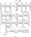
FIG. 6 is a schematic structural diagram of a semantic segmentation network according to an embodiment of the present disclosure. -
FIG. 7 is a schematic diagram of a process of determining a target image region by using a preset second region detection model according to an embodiment of the present disclosure. -
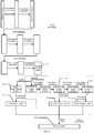
FIG. 8 is a schematic structural diagram of a target detection network according to an embodiment of the present disclosure. -
FIG. 9 is a schematic structural diagram of a node recognition network according to an embodiment of the present disclosure. -
FIG. 10 is a schematic structural diagram of a recognition model for recognizing an object node in an image according to an embodiment of the present disclosure. -
FIG. 11 is a diagram showing a scenario applying a recognition model according to an embodiment of the present disclosure. -
FIG. 12 is a schematic structural diagram of an apparatus for recognizing an object node in an image according to an embodiment of the present disclosure. -
FIG. 13 is a schematic structural diagram of an intelligent terminal according to an embodiment of the present disclosure. - To make the objectives, technical solutions, and advantages of the present disclosure clearer, the following further describes the technical solution of the present disclosure in detail with reference to the accompanying drawings and the embodiments. It is to be understood that the specific embodiments described herein are only used to describe the technical solution of the present disclosure, instead of limiting the technical solution of the present disclosure.
- In the embodiments of the present disclosure, a method for recognizing an object node in an image is provided. The recognition method includes detecting and cropping an original image to obtain a subimage including a target image object, and then invoking a preset node recognition model to perform node recognition on the subimage, to obtain node recognition information of the target image object included in the original image. In the embodiments of the present disclosure, during a node recognition process, node recognition may only be performed on the subimage, instead of the entire original image, to avoid recognizing other image objects similar to the target image object in the original image, thereby improving the precision of image recognition.
- In an embodiment, the method for recognizing an object node in an image may be applied to hand gesture skeleton recognition. The so-called hand gesture skeleton recognition means recognizing main joint points of a hand in an image, and then connecting the recognized joint points in a preset manner to form a skeleton image of the hand. 22 nodes of a palm are used as an example, as shown in
FIG. 1 to FIG. 2. FIG. 1 shows a hand gesture of an open palm. Through hand gesture skeleton recognition, a hand gesture skeleton image corresponding to the hand gesture inFIG. 1 may be recognized, and the hand gesture skeleton image may be as shown inFIG. 2 . The recognition method in the embodiments of the present disclosure may also be used for recognizing a hand gesture inFIG. 3a . According to the embodiments of the present disclosure, not only the V hand gesture inFIG. 3a but also abend node 1 of a ring finger, abend node 2 of a little finger, ajunction 3 of a thumb and the ring finger, and other hidden nodes can be recognized, thereby obtaining a hand gesture skeleton image shown inFIG. 3b . It can be seen that, the method for recognizing an object node in an image according to the embodiments of the present disclosure can recognize key nodes (including hidden nodes) of the entire palm, and a joint position and direction of each finger of the palm can be recognized based on the recognized key nodes, thereby obtaining a hand gesture skeleton image. In the present disclosure, 2D coordinates of a hand gesture skeleton may be predicted based on an image generated by a camera of a device such as an intelligent terminal, and a position and a direction of any joint point of a hand may be recognized. - According to an embodiment of the present disclosure, a schematic flowchart of a method for recognizing an object node in an image is provided, as shown in
FIG. 4 . The method in this embodiment of the present disclosure may be implemented by an intelligent terminal. The intelligent terminal may be, for example, a mobile intelligent terminal such as a smartphone or a tablet computer, or may be an intelligent terminal that performs man-machine interaction based on hand gesture recognition, such as a motion sensing game device with a camera or a motion sensing control device with a camera. - In startup, such intelligent terminals may turn on a camera to acquire data. In
S 101, a to-be-recognized original image may be obtained by the camera. The original image includes a target image object. The target image object mainly includes a palm of a user. The user is required to put the palm in a shooting range of the camera, so that the palm can be photographed for hand gesture skeleton recognition. Initial hand gesture recognition and estimation may be performed on the image taken by the camera. If it is recognized that the image does not include a palm, this step is performed continuously. - The terminal may obtain a to-be-recognized original image according to a processing instruction inputted by the user. For example, when the user wants to know node information of the target image object in the original image, the user may input a processing instruction to the terminal, to instruct the terminal to obtain the to-be-recognized original image and perform node recognition processing on the original image. The processing instruction may be a press instruction or a click instruction to the terminal, or a voice instruction transmitted to the terminal, or the like, and is not limited in this embodiment of the present disclosure. In an embodiment, the terminal may further actively obtain the to-be-recognized original image according to a service requirement, and perform node recognition processing on the original image. For example, the service requirement may be hand gesture photographing. When the user uses a hand gesture to take a photo, the terminal may take an image only after a specified hand gesture of the user is detected. Therefore, after detecting that the user enables a camera function of the terminal, the terminal actively obtains a to-be-recognized original image taken by a camera component, and performs node recognition processing on the original image.
- After obtaining the original image including the target image object, in
S 102, image detection may be performed on the original image, to determine a target image region in the original image. Determining the target image region is not determining an image region randomly, but determining an image region including the target image object as the target image region. The terminal may perform image detection on the original image by using an image object detection method, to determine the target image region in the original image. The image object detection method is a method for positioning a target of interest in an image by using theories and methods in fields such as image processing and mode recognition, and giving a boundary box of each target after accurately determining a specific category of each target. - In an embodiment, a specific implementation of performing image detection on the original image to determine a target image region in the original image may be as follows. A preset first region detection model is invoked to perform image feature recognition on the original image, to obtain a region probability matrix, where an element value Auv in the region probability matrix represents a probability that a corresponding pixel point Ouv in the original image belongs to the target image region, u represents a row number, and v represents a column number. Binarization processing is performed on the region probability matrix by using a preset threshold, to obtain a feature element value region. The target image region is determined according to the feature element value region. For a specific process, one may refer to
FIG. 5 . Data features of an inputtedoriginal image 10 may be extracted first, to determine an initial image region including a target image object. Then, pixel-level recognition is performed on theoriginal image 10. The so-called pixel-level recognition refers to recognizing, for each pixel in the image, a type of target image that the pixel belongs to, and sequentially determining, for each pixel in theoriginal image 10, whether the pixel is a pixel in the initial image region. In an embodiment, theoriginal image 10 may be stored as an array in a computer, and a value of each pixel (element) in the array is brightness (gray scale) of an image point. Therefore, a rectangular coordinate system, that is, a pixel plane coordinate system u-v, may be defined on theoriginal image 10. Coordinates (u, v) of each pixel represent a row number and a column number of the pixel in the array. Therefore, it may be determined, for each pixel in theoriginal image 10, whether the pixel is in the initial image region according to the pixel coordinates of the pixel. - After recognition of all pixels is completed, a region probability matrix having a same resolution as the
original image 10 may be obtained. Then, the preset first region detection model may perform binarization processing on the region probability matrix by using a preset threshold, to obtain a binary image, that is, a featureelement value region 22. Specifically, first of all, it is sequentially determined whether probability values of the region probability matrix are greater than the preset threshold. A position at which a probability value is less than the threshold is represented by a black color on the binary image, and a position at which a probability value is greater than or equal to the threshold is represented by a white color on the binary image, thereby obtaining the featureelement value region 22 shown inFIG. 5 . Then, the target image region is determined according to the featureelement value region 22. - In the process of obtaining the feature
element value region 22, due to factors such as a calculation error, the obtained featureelement value region 22 may include multiple white regions, for example, ascattered region 222 and ascattered region 223 inFIG. 5 . Therefore, in an embodiment, a specific implementation of determining the target image region according to the featureelement value region 22 may include: determining a maximumcontinuous region 221 according to pixel coordinates of each pixel value in the featureelement value region 22; and determining the target image region according to pixel coordinates of each pixel value in the maximumcontinuous region 221. Specifically, a maximum u value and a minimum u value are determined on a horizontal u axis of the featureelement value region 22, and a maximum v value and a minimum v value are determined on a vertical v axis of the featureelement value region 22. Then, the target image region is determined according to the determined maximum u value, minimum u value, maximum v value and minimum v value. The shape of the target image region may be a rectangular frame. - The maximum u value may represent a horizontal coordinate of a rightmost pixel point in the maximum continuous region, or may represent a horizontal coordinate obtained by extending rightward by Z pixel points from the rightmost pixel point in the maximum continuous region. The minimum u value may represent a horizontal coordinate of a leftmost pixel point in the maximum continuous region, or may represent a horizontal coordinate obtained by extending leftward by Z pixel points from the leftmost pixel point in the maximum continuous region. The maximum v value may represent a vertical coordinate of a lowermost pixel point in the maximum continuous region, or may represent a vertical coordinate obtained by extending downward by Z pixel points from the lowermost pixel point in the maximum continuous region. The minimum v value may represent a vertical coordinate of an uppermost pixel point in the maximum continuous region, or may represent a vertical coordinate obtained by extending upward by Z pixel points from the uppermost pixel point in the maximum continuous region. Z is a positive integer. For example, Z is any positive integer from 1 to 5.
- In an embodiment, the first region detection model may be a detection model based on a convolutional neural network. The first region detection model may be optimized using multiple sample images and annotated images corresponding to the sample images, to obtain the preset first region detection model. The annotated image refers to a sample image annotated with a corresponding target image region. In a process of optimizing the first region detection model, a sample image may be first inputted to the first region detection model, and the first region detection model may perform image detection on the sample image, to obtain a detected image. Then, the detected image may be compared with a corresponding annotated image, and then parameters in the first region detection model, such as a convolution parameter in the convolutional neural network, are optimized according to a comparison result. The first region detection model is optimized multiple times by using multiple sample images and corresponding annotated images, until that for each sample image, the comparison result between the annotated image corresponding to the sample image and the detected image obtained by the first region detection model performing image detection on the sample image meets a preset condition, to finally obtain the preset first region detection model.
- In a case that the target image object occupies a small proportion of area of the original image, there may be a recognition error in the image detection performed on the original image using the foregoing preset first region detection model (that is, the detection model based on the convolutional neural network). Therefore, in addition to the detection model based on the convolutional neural network, an embodiment of the present disclosure provides another preset first region detection model, which may be a model based on an optimized semantic segmentation network. The semantic segmentation network can not only perform convolution calculation on the original image to extract an image feature in the original image, but also perform downsampling processing and upsampling processing on the extracted image feature. The downsampling processing can reduce a resolution of the image feature, to reduce data points of non-target image objects in the original image, thereby improving recognition precision. The upsampling processing can increase the resolution of the image feature, so that a resolution of the finally obtained region probability matrix is the same as a resolution of the original image. Therefore, the preset first region detection model can accurately determine the target image region according to the region probability matrix.
- The semantic segmentation network can perform image detection and pixel recognition on the original image, to obtain the region probability matrix. Therefore, the semantic segmentation network can be optimized by using multiple sample images and corresponding sample probability matrices. In the optimization process, sample images may be inputted to the semantic segmentation network, so that a series of operations including image detection are performed, to obtain detected probability matrices. Then, the detected probability matrices are compared with the corresponding sample probability matrices. Parameters in the semantic segmentation network, such as a convolution parameter, a downsampling parameter, an upsampling parameter and a fusion parameter, are optimized according to comparison results.
- In an embodiment, a schematic structural diagram of the semantic segmentation network is shown in
FIG. 6 . Correspondingly, a specific implementation of invoking a preset first region detection model to perform image feature recognition on the original image to obtain a region probability matrix may include: performing convolution calculation on the original image, to obtain a first image feature; and performing, on the first image feature, first processing based on downsampling, to obtain a second image feature, where a resolution of the second image feature obtained by the first processing is lower than a resolution of the first image feature. The first image feature is obtained by performing convolution calculation on the original image. By performing, on the first image feature, the first processing based on downsampling, the resolution of the image feature can be reduced, to reduce data points of non-target image objects in the original image, thereby recognizing the target image object more accurately, and thus improving the recognition precision. - In an embodiment, the first processing based on downsampling includes N downsampling processes and M sets of convolution calculation processes. The downsampling processes include a downsampling process on the first image feature and a downsampling processes on a downsampled image feature obtained by each set of convolution calculation processes. N and M both are positive integers. In an embodiment, the downsampling processes and the sets of convolution calculation processes are performed alternately, and the second image feature is an image feature obtained by the M-th set of convolution calculation.
- After the second image feature is obtained, second processing based on upsampling and fusion may be performed on the second image feature, to obtain a target image feature, a resolution of the target image feature obtained by the second processing being the same as a resolution of the original image. The region probability matrix is obtained according to the target image feature. Therefore, the second processing based on upsampling and fusion is performed on the second image feature, so that the resolution of the image feature may be increased through upsampling, and by fusing feature information of different feature dimensions, the resolution of the target image feature obtained by the second processing is the same as the resolution of the original image and the target image feature is more robust. In this way, the resolution of the finally obtained region probability matrix is the same as the resolution of the original image, so that the preset first region detection model can accurately determine the target image region according to the region probability matrix.
- In an embodiment, the second processing based on upsampling and fusion includes N upsampling processes, N feature fusion processes and M sets of deconvolution calculation processes. The upsampling processes includes an upsampling process on the second image feature and an upsampling process on an image feature obtained by each set of deconvolution calculation processes. Each feature fusion processes is a fusing process on an image feature obtained by each of the upsampling processes and the first image feature or a corresponding downsampled image feature that has a same resolution as the image feature.
- In an embodiment, the upsampling processes and the sets of deconvolution calculation processes may be performed alternately, and after completion of each upsampling process, a feature fusion process is performed on an image feature obtained by the upsampling process and corresponding downsampled image feature that has the same resolution as the image feature, to obtain a fused image feature. Then, deconvolution calculation processing is performed on the fused image feature. The N-th feature fusion process is fusing an image feature obtained by the N-th upsampling process with the first image feature, and the target image feature is an image feature obtained by the M-th sets of deconvolution calculation processes. Deconvolution calculation is performed on the target image feature, to obtain the region probability matrix. By performing downsampling processing and convolution calculation processing on the image feature alternately, features of the original image can be extracted from visual features (such as the shape, texture, and color) to semantic features. Values of N and M may be determined according to an actual service requirement. Experiments show that the obtained probability matrix is more accurate with a greater value of N.
- In another embodiment, a specific implementation of performing image detection on an original image to a target image region in the original image may include: invoking a preset second region detection model to process the original image, to obtain four-tuple data, and determining the target image region according to the four-tuple data. The second region detection model performs image feature extraction processing on the original image, and obtains the four-tuple data according to the extracted image feature. The four-tuple data includes a u-direction offset (a first offset) and a v-direction offset (a second offset) relative to a central point of the target image region, as well as a width value and a height value of the target image region. Based on u, v, the width and the height, the target image region may be obtained.
-
FIG. 7 shows a specific process of invoking a preset second region detection model to determine a target image region. An image feature of theoriginal image 10 may be extracted first. Then, four-tuple data is obtained according to the extracted image feature. Finally, a region position in the original image may be determined according to a first offset and a second offset in the four-tuple data, a region size is determined according to a width value and a height value in the four-tuple data, and the target image region is obtained according to the region position and the region size. - In an embodiment, a specific implementation of determining the target image region according to the four-tuple data by the second region detection model may be as follows. For example, a rectangular frame is used for representing the target image region. The four-tuple data includes a u-direction offset and a v-direction offset relative to a central point of the target image region, as well as a width and a height of the target image region, as shown by 25 in
FIG. 7 . The u-direction offset refers to an offset of a vertex at the upper left corner of the rectangular frame relative to the central point in a u direction, and the v-direction offset refers to an offset of the vertex at the upper left corner of the rectangular frame relative to the central point in a v direction. Therefore, coordinates of the central point may be recognized, and then coordinates of the vertex at the upper left corner of the rectangular frame may be determined according to the coordinates of the central point, the u-direction offset, and the v-direction offset. The size of the rectangular frame is determined according to the coordinates of the vertex at the upper left corner and the width and height values in the four-tuple data, as shown by 30 inFIG. 7 . In other embodiments, the u-direction offset and the v-direction offset may refer to a u-direction offset and a v-direction offset of another vertex (such as coordinates of a vertex at an upper right corner) of the rectangular frame relative to the central point. - In an embodiment, the second region detection model may be a detection model based on a convolutional neural network. The second region detection model may be optimized using multiple sample images and corresponding annotated images, to obtain the preset second region detection model. The optimization process of the second region detection model is similar to the foregoing optimization process of the first region detection model. In an embodiment, the sample images and four-tuple data of a target image region that includes a target image object in each sample image are already known. After the sample images are inputted to a constructed detection model based on the convolutional neural network, if finally outputted four-tuple data is the same as the known four-tuple data of the sample images or meets a preset error, it is considered that the constructed detection model based on the convolutional neural network can well perform the prediction. Otherwise, related parameters in the constructed detection model based on the convolutional neural network need to be adjusted. After recognizing numerous sample images including various hand gestures, the second region detection model, which is capable of recognizing the target image object in the original image that includes a hand gesture, may be finally obtained.
- In another embodiment, in addition to the above detection model based on the convolutional neural network, an embodiment of the present disclosure provides another preset second region detection model, which may be a model based on an optimized target detection network. The target detection network can not only perform convolution calculation on the original image to extract an image feature in the original image, but also perform downsampling processing, feature fusion processing, dimension conversion, and the like on the extracted image feature, to obtain four-tuple data. The downsampling processing can reduce a resolution of the image feature, to reduce data points of non-target image objects in the original image, thereby improving recognition precision. By the feature fusion processing, a more robust image feature may be learned by using information of different feature dimensions. Through dimension conversion, the image feature may be converted into a feature vector, so that feature fusion processing can be performed to obtain four-tuple data, thereby improving processing efficiency.
- An initially constructed target detection network may be optimized by using multiple sample images and corresponding sample four-tuple data, to finally obtain the preset second region detection model. In the optimization process, sample images may be inputted to the target detection network, so that a series of operations including image feature extraction are performed, to obtain detected four-tuple data. The detected four-tuple data is compared with the sample four-tuple data. Parameters of the target detection network, such as a downsampling parameter, a convolution calculation parameter, and a feature fusion processing parameter, are optimized according to a comparison result.
- In an embodiment, a schematic structural diagram of the target detection network is shown in
FIG. 8 . Correspondingly, a specific implementation of processing the original image by using the preset second region detection model to obtain four-tuple data may include: performing convolution calculation on the original image to obtain a third image feature; and performing third processing on the third image feature, to obtain a fourth image feature. The third processing includes R downsampling processes and S sets of convolution calculation processes, and the downsampling processes include a downsampling process on the third image feature and a downsampling process on an image feature obtained by each set of convolution calculation processes, where R and S both are positive integers. In an embodiment, the downsampling operations and the sets of convolution calculation processing may be performed alternately. By performing downsampling processing and convolution calculation processing on the image feature alternately, features of the original image can be extracted from visual features (such as the shape, texture, and color) to semantic features. Values of R and S may be determined according to an actual service requirement. Experiments show that the finally obtained four-tuple data is more accurate with a greater value of R. - Fourth processing is performed on the fourth image feature to obtain an intermediate image feature. The fourth processing includes convolution calculation processing. Dimension conversion is performed on the fourth image feature, to obtain a first feature vector. Dimension conversion is performed on the intermediate image feature, to obtain a second feature vector. Feature fusion is performed on the first feature vector and the second feature vector to obtain the four-tuple data.
- In an embodiment, the fourth processing may further include: performing downsampling processing on the fourth image feature, and performing convolution calculation processing on an intermediate image feature obtained by the downsampling processing. Correspondingly, a specific implementation of performing dimension conversion on the fourth image feature to obtain a first feature vector may include: performing scaling processing on the fourth image feature to obtain a scaled fourth image feature, a resolution of the scaled fourth image feature being the same as a resolution of the intermediate image feature; and performing dimension conversion on the scaled fourth image feature to obtain the first feature vector.
- There may be more than one intermediate image feature. For example, as shown in
FIG. 8 , afourth image feature 101 and intermediate image features 102 and 103 are selected as an example. Because the resolution of 101 is higher than that of 102 and 103, scaling processing is performed on 101, to obtain a scaledfourth image feature 104. Then, dimension conversion is performed on 104, to obtain afirst feature vector 105, and dimension conversion is performed on 102 and 103 respectively, to obtainsecond feature vectors tuple data 108. - After the target image region is determined through the foregoing method, in
S 103, image cropping may be performed on the original image according to the target image region, to obtain a subimage including the target image object. In the process, first the image cropping may be performed on the original image according to the target image region, to obtain a cropped image, the cropped image including the target image object, and a size of the cropped image being not larger than a size of the target image region. Then, a resolution of the cropped image is adjusted to obtain the subimage, a resolution of the subimage being a target resolution. After the image cropping is completed to obtain the subimage, a node recognition model can subsequently recognize a node position more quickly and accurately. - After the subimage having the target resolution is obtained, in
S 104, a preset node recognition model is invoked to perform node recognition on the subimage, to obtain node recognition information of the target image object. In an embodiment, the node recognition model may be a recognition model based on a convolutional neural network. The node recognition model may be optimized using multiple sample images and corresponding sample node recognition information, to obtain the preset node recognition model. In the optimization process, sample images may be inputted to the node recognition model for node recognition, to obtain detected node recognition information. The detected node recognition information is compared with the corresponding sample node recognition information, and parameters of the node recognition model are optimized according to a comparison result. The node recognition model is optimized multiple times by using multiple sample images and corresponding sample node recognition information, until that, for each sample image, the comparison result between sample node recognition information corresponding to the sample image and detected node recognition information obtained by the node recognition model performing node recognition on the sample image meets a preset condition, to obtain the preset node recognition model. - In an embodiment, in addition to the recognition model based on the convolutional neural network, an embodiment of the present disclosure provides another preset node recognition model, which may be a model based on an optimized node recognition network. The node recognition network can not only perform convolution calculation processing on the subimage to extract an image feature in the subimage, but also learn node information of the extracted image feature at least twice. In the learning process, downsampling processing, upsampling processing, and feature fusion processing may be performed on the extracted image feature. The downsampling processing can reduce the resolution of the image feature and increase a receptive field of a convolution kernel, thereby improving recognition precision. The upsampling processing can increase the resolution of the image feature. With a higher resolution of the image feature obtained by the upsampling processing, the node position is more precise. Through the feature fusion processing, feature fusion learning may be performed on the recognized intermediate node recognition information and a high-resolution image feature, thereby correcting and fine-tuning the node position and structure and improving the precision of node recognition information.
- For the node recognition model, parameters in the node recognition network, such as a convolution processing parameter, a downsampling processing parameter, a feature fusion processing parameter, and an upsampling processing parameter, may be optimized by using multiple sample images and known node probability matrices corresponding to the sample images, to obtain the preset node recognition model by training and optimizing the initially constructed node recognition network. In an embodiment, after the sample images are inputted to the initially constructed node recognition network, the initially constructed node recognition network may perform a series of operations including convolution calculation, node recognition processing, node information prediction processing and node information adjustment processing on the sample images.
- After receiving the sample images, the initially constructed node recognition network may perform convolution calculation on the sample images to obtain convolutional image features. In the node recognition processing, the node recognition network may perform downsampling processing and convolution calculation processing on the convolutional image features to obtain first node recognition features, and then perform downsampling and convolution calculation on the first node recognition features, to obtain intermediate node recognition features. The node recognition network may perform node information prediction processing on the intermediate node recognition features, to obtain at least one group of initial node probability matrices. Each group of initial node probability matrices includes node probability matrices of P channels. The node probability matrix of each channel represents a probability distribution state of a position of a node in the sample image. A value of P depends on a node quantity in the sample image. The node recognition network may invoke a loss function to perform a loss value calculation on the initial node probability matrix and a known node probability matrix corresponding to the sample image, and parameters in the node recognition network are optimized according to a calculation result. The node recognition feature mentioned above refers to an image feature corresponding to a node in the target image object.
- After the node information prediction processing is completed, a second node recognition feature may be obtained. The node recognition network may perform node information adjustment processing on the second node recognition feature, to obtain a final node probability matrix of the sample image. After recognizing numerous sample images with known node probability matrices, the preset node recognition model, which is capable of performing node recognition on the subimage including the target image object, may be finally obtained.
- In an embodiment, a schematic structural diagram of the node recognition network is shown in
FIG. 9 . Correspondingly, a specific implementation of invoking a preset node recognition network to perform node recognition on the subimage to obtain node recognition information of the target image object may include: performing node recognition on the subimage, to obtain node probability matrices of P channels, the node probability matrix of each channel representing a probability distribution state of a position of a node in the original image, and a value of P being equal to a node quantity in the target image object; and obtaining the node recognition information of the target image object according to the node probability matrices of the P channels, the node recognition information including image position information of each node of the target image object in the original image. In an embodiment, the probability distribution state of the position in the original image of each node of the target image object may be obtained according to the node probability matrices of the P channels first, and then the node recognition information of the target image object is obtained according to the probability distribution state of the position in the original image of each node of the target image object. - In an embodiment, a specific implementation of performing node recognition on the subimage to obtain node probability matrices of P channels may include: performing convolution calculation on the subimage to obtain a convolutional image feature; performing node recognition processing on the convolutional image feature, to obtain a first node recognition feature, the node recognition processing including K downsampling processes and J sets of convolution calculation processes, and the downsampling processes including a downsampling process on the convolutional image feature and a downsampling process on a downsampled node recognition feature obtained by each set of convolution calculation processes, and K and J both being positive integers; and obtaining the node probability matrices of the P channels according to the first node recognition feature.
- In an embodiment, a specific implementation of obtaining the node probability matrices of the P channels according to the first node recognition feature may include: performing convolution calculation on the first node recognition feature at least once, to obtain the node probability matrices of the P channels. In another embodiment, downsampling processing may be performed on the first node recognition feature first, and then convolution calculation is performed at least once on the first node recognition feature obtained by the downsampling processing, to obtain the node probability matrices of the P channels.
- In another embodiment, a specific implementation of obtaining the node probability matrices of the P channels according to the first node recognition feature may alternatively include: obtaining a second node recognition feature according to the first node recognition feature; performing node information adjustment processing on the first node recognition feature and the second node recognition feature, to obtain the node probability matrices of the P channels. The node information adjustment processing includes X sets of convolution calculation processes, Y upsampling processes and Y feature fusion processes. The upsampling processes include an upsampling process on the second node recognition feature and/or an upsampling process on a node recognition feature obtained by each set of convolution calculation processes. The feature fusion processes include a fusing process on a node recognition feature obtained by each upsampling processes and a corresponding downsampled node recognition feature having a same resolution as the node recognition feature. The convolution calculation processes include a convolution calculation process on a fused node recognition feature obtained by the feature fusion process. X and Y are both positive integers. The first node recognition feature may also be referred to as a downsampled node recognition feature. If the first node recognition feature has the same resolution as the second node recognition feature, upsampling processing may not be performed on the second node recognition feature, and feature fusion may be directly performed on the second node recognition feature and the first node recognition feature.
- In an embodiment, in the process of obtaining the second node recognition feature according to the first node recognition feature, downsampling processing and/or convolution calculation processing may be performed on the first node recognition feature, to obtain an intermediate node recognition feature. Node information prediction processing is performed on the intermediate node recognition feature, to obtain the second node recognition feature. In an embodiment, a set of convolution calculation processing may be performed on the intermediate node recognition feature, to obtain a probability matrix. The probability matrix, together with a loss function, may be used for optimizing parameters of the node recognition model in the process of optimizing the node recognition model. In the process of performing a set of convolution calculation processing on the intermediate node recognition feature, other intermediate node recognition features may be obtained, and at least two intermediate node recognition features may be selected for feature fusion, to obtain the second node recognition feature.
- In another embodiment, the process of the node information prediction processing may be as that shown in
FIG. 9 . The node information prediction processing includes A sets of convolution calculation processes and B feature fusion processes. The feature fusion process is processing of feature fusion performed on an intermediate node recognition feature inputted to a set of convolution calculation processes and a probability matrix obtained by the convolution calculation processes. Moreover, the intermediate node recognition feature obtained by each feature fusion process is used as a node recognition feature to be inputted to the next set of convolution calculation processes. The B-th feature fusion is processing of feature fusion performed according to at least two intermediate node recognition features in the A-th set of convolution calculation processing, where A and B are both positive integers. For example, values of A and B are both 2, that is, two sets of convolution calculation processing and two feature fusion processing operations are performed. As shown inFIG. 9 , an intermediatenode recognition feature 201 is selected as a node recognition feature to be inputted to the first set of convolution calculation processing. A set of convolution calculation processing may be performed on 201 first, to obtain aprobability matrix 202. Then, the first feature fusion is performed on 201 and 202, to obtain an intermediatenode recognition feature 203. 203 is used as a node recognition feature to be inputted to the second set of convolution calculation processing, and the second set of convolution calculation processing is performed on 203, to obtain anintermediate node feature 204 and aprobability matrix 205. Then, the second feature fusion is performed on 203 and 204, to obtain a second node recognition feature. Both theprobability matrices - In an embodiment, the node recognition information includes image position information of each node of the target image object in the original image. After the node recognition information of the target image object is obtained, a node connection image of the target image object may further be obtained according to the node recognition information of the target image object. For example, if the target image object is a hand, the node recognition information of the target image object may include position information and direction information of key nodes of a palm. The nodes may be connected in a preset connection order according to the position information and direction information of the key nodes, thereby obtaining a hand gesture skeleton image. For example, the nodes of the palm shown in
FIG. 1 may be numbered in advance, and the preset connection order may be: 1-2-3-4-21-22, 5-6-7-8-21-22, 9-10-11-12-21-22, 13-14-15-16-21-22, and 17-18-19-20-21-22. After the position information and the direction information of the nodes are obtained, the hand gesture skeleton image shown inFIG. 2 may be determined according to the preset connection order. - In an embodiment, after the node connection image of the target image object is obtained, the node connection image may be outputted in a coordinate system. In another embodiment, the node connection image may alternatively be superposed onto the original image, to obtain and display the superposed image.
- In this embodiment of the present disclosure, after a to-be-recognized original image is obtained, through image detection and cropping, a subimage including a target image object is inputted to a node recognition network for node recognition, to avoid the problem of inaccurate node recognition in a case that a target image region occupies a small proportion of area of the original image, thereby improving the recognition precision and meeting the requirement of elaborate hand gesture recognition.
- Steps in the flowchart in
FIG. 4 are displayed in sequence indicated by the arrows, but the steps are not necessarily performed sequentially in the sequence indicated by the arrows. Unless otherwise explicitly specified in the present disclosure, execution of the steps is not strictly limited, and the steps may be performed in other sequences. In addition, at least some steps inFIG. 4 may include multiple substeps or multiple stages. The substeps or the stages are not necessarily performed at the same moment, but may be performed at different moments. The substeps or the stages are not necessarily performed in sequence, but may be performed in turn or alternately with another step or at least some of substeps or stages of another step. - Based on the description of the foregoing method embodiment, an embodiment of the present disclosure further provides a schematic structural diagram of a recognition model for recognizing an object node in an image, as shown in
FIG. 10 . The schematic structural diagram may be formed by aregion detection model 20, ajoin module 40 in the middle, and anode recognition model 60. Theregion detection model 20 is configured to perform image detection on a to-be-recognized original image, and determine a target image region in the original image. Thejoin module 40 is configured to perform image cropping on the original image according to the target image region, to obtain a subimage including a target image object. Thenode recognition model 60 is configured to perform node recognition on the subimage, to obtain node recognition information of the target image object. In an embodiment, the target image object may be a hand. - Hand gesture skeleton recognition is used as an example to describe this embodiment of the present disclosure in detail. As shown in
FIG. 11 , a to-be-processedoriginal image 10 may be obtained first, the original image including a hand gesture (that is, a target image object). Theoriginal image 10 may be inputted to theregion detection model 20. Theregion detection model 20 may perform image detection on theoriginal image 10, to obtain a detected image. The detected image is an image in which a target image region is determined in the original image. After theregion detection model 20 performs the image detection, the obtained detected image may be as shown by 30 inFIG. 11 , where a rectangular frame in 30 may represent the target image region. Then, the detectedimage 30 is inputted to thejoin module 40. After receiving 30, thejoin module 40 may crop theoriginal image 10 according to the target image region (such as the rectangular frame), to obtain asubimage 50 including a hand gesture. Then thesubimage 50 is inputted to thenode recognition model 60. Thenode recognition model 60 may perform node recognition on thesubimage 50, to obtain node recognition information of the hand gesture (that is, the target image object). A node connection image shown by 70 or a node connection image shown by 80 may be obtained and displayed according to the node recognition information. In an embodiment, the node recognition information may include position information and direction information of main key nodes of a palm. After the node recognition information is obtained, a hand gesture skeleton image (that is, a node connection image of the target image object) may be obtained according to the node recognition information. - In an embodiment, the
region detection model 20 may be the preset first region detection model described in the foregoing method embodiment, or may be the preset second region detection model described in the foregoing method embodiment. Thenode recognition model 60 may be the preset node recognition model described in the foregoing method embodiment. In this embodiment of the present disclosure, in designing the noderecognition network model 60, performance characteristics of a terminal device (such as a mobile phone) are further taken into consideration, to make specific design and optimization. - It can be learned from the above description that the recognition model for recognizing an object node in an image is formed by the
region detection model 20 and thenode recognition model 60 that are connected in series through thejoin module 40, and has the following advantages. - The recognition model has advantages of flexibility, high extensibility, and high reusability. The
region detection model 20 and thenode recognition model 60 are separated by thejoin module 40, so that specific design and optimization can be made for each model separately. For example, the node recognition model is not required to have high accuracy of recognizing the target image region. Therefore, in the present disclosure, detection accuracy of the target image region may be sacrificed to a certain extent to improve the execution performance of the network. In this way, the entire network can run more smoothly on the terminal device. - Networks in the models can be disassembled and assembled flexibly. For example, the network in the
region detection model 20 may be the semantic segmentation network shown inFIG. 6 or the target detection network shown inFIG. 8 . Thenode recognition model 60 may be the node recognition network shown inFIG. 9 . With such a cascade structure, the updating of the network in theregion detection model 20 does not unnecessarily require modification of the node recognition network shown inFIG. 9 . - The recognition model has advantages of high accuracy and excellent performance. The
region detection model 20 may find the target image region first. Thejoin module 40 obtains the target image region through cropping and then transmits the target image region to thenode recognition model 60. In this way, thenode recognition model 60 can focus on learning nodes and the structure between nodes, without paying attention to redundant information of numerous non-target image objects, thereby greatly improving the recognition accuracy, reducing the complexity of the model, and improving the performance of the model. - Based on the description of the foregoing method embodiment, an embodiment of the present disclosure further provides a schematic structural diagram of an apparatus for recognizing an object node in an image, as shown in
FIG. 12 . As shown inFIG. 12 , the recognition apparatus in this embodiment of the present disclosure may include: - an obtaining
unit 301, configured to obtain a to-be-recognized original image, the original image including a target image object; - a
detection unit 302, configured to perform image detection on the original image, to determine a target image region in the original image, the target object region including the target image object; - a
cropping unit 303, configured to perform image cropping on the original image according to the target image region, to obtain a subimage including the target image object; and - a
recognition unit 304, configured to invoke a preset node recognition model to perform node recognition on the subimage, to obtain node recognition information of the target image object. - In an embodiment, the
detection unit 302 may be specifically configured to: invoke a preset first region detection model to perform image feature recognition on the original image, to obtain a region probability matrix, an element value Auv in the region probability matrix representing a probability that a corresponding pixel point Ouv in the original image belongs to the target image region, u representing a row number, and v representing a column number; perform binarization processing on the region probability matrix by using a preset threshold, to obtain a feature element value region; and determine the target image region according to the feature element value region. - In an embodiment, a specific implementation of invoking a preset first region detection model to perform image feature recognition on the original image to obtain a region probability matrix may include: performing convolution calculation on the original image, to obtain a first image feature; performing, on the first image feature, first processing based on downsampling, to obtain a second image feature, where a resolution of the second image feature obtained by the first processing is lower than a resolution of the first image feature; performing, on the second image feature, second processing based on upsampling and fusion, to obtain a target image feature, where a resolution of the target image feature obtained by the second processing is the same as a resolution of the original image; and performing deconvolution calculation on the target image feature, to obtain the region probability matrix.
- In an embodiment, the first processing based on downsampling includes N downsampling processes and M sets of convolution calculation processes, and the downsampling processes include a downsampling process on the first image feature and a downsampling process on a downsampled image feature obtained by each set of convolution calculation processes, N and M both being positive integers.
- The second processing based on upsampling and fusion includes N upsampling processes, N feature fusion processes and M sets of deconvolution calculation processes. The upsampling processes include an upsampling process on the second image feature and an upsampling process on an image feature obtained by each set of deconvolution calculation processes, and the feature fusion processes include a fusing process on an image feature obtained by each of the upsampling processes and a corresponding downsampled image feature that has a same resolution as the image feature.
- In an embodiment, the
detection unit 302 may be specifically configured to: invoke a preset second region detection model to process the original image to obtain four-tuple data, where the second region detection model performs image feature extraction processing on the original image and obtains the four-tuple data according to an extracted image feature; determine a region position in the original image according to a first offset and a second offset in the four-tuple data; determine a region size according to a width value and a height value in the four-tuple data; and obtain the target image region according to the region position and the region size. - In an embodiment, a specific implementation of processing the original image by using the preset second region detection model to obtain the four-tuple data may include: performing convolution calculation on the original image to obtain a third image feature; performing third processing on the third image feature, to obtain a fourth image feature, the third processing including R downsampling processes and S sets of convolution calculation processes, and the downsampling processes including a downsampling process on the third image feature and a downsampling process on an image feature obtained by each set of convolution calculation processes, and R and S both being positive integers; performing fourth processing on the fourth image feature, to obtain an intermediate image feature, the fourth processing including convolution calculation processing; performing dimension conversion on the fourth image feature to obtain a first feature vector, and performing dimension conversion on the intermediate image feature to obtain a second feature vector; and performing feature fusion on the first feature vector and the second feature vector to obtain the four-tuple data.
- In an embodiment, the fourth processing further includes: performing downsampling processing on the fourth image feature, and performing convolution calculation processing on an image feature obtained by the downsampling processing. Correspondingly, a specific implementation of performing dimension conversion on the fourth image feature to obtain a first feature vector may include: performing scaling processing on the fourth image feature to obtain a scaled fourth image feature, a resolution of the scaled fourth image feature being the same as a resolution of the intermediate image feature; and performing dimension conversion on the scaled fourth image feature to obtain the first feature vector.
- In an embodiment, a specific implementation of invoking a preset node recognition model to perform node recognition on the subimage to obtain node recognition information of the target image object may include: performing node recognition on the subimage, to obtain node probability matrices of P channels, the node probability matrix of each channel representing a probability distribution state of a position of a node in the original image, and a value of P being equal to a node quantity in the target image object; and obtaining the node recognition information of the target image object according to the node probability matrices of the P channels, the node recognition information including image position information of each node of the target image object in the original image.
- In an embodiment, a specific implementation of performing node recognition on the subimage to obtain node probability matrices of P channels may include: performing convolution calculation on the subimage to obtain a convolutional image feature; performing node recognition processing on the convolutional image feature, to obtain a first node recognition feature, the node recognition processing including K downsampling processes and J sets of convolution calculation processes, and the downsampling processes including a downsampling process on the convolutional image feature and a downsampling process on a downsampled node recognition feature obtained by each set of convolution calculation processes, and K and J both being positive integers; and obtaining the node probability matrices of the P channels according to the first node recognition feature.
- In an embodiment, a specific implementation of obtaining the node probability matrices of the P channels according to the first node recognition feature may include: obtaining a second node recognition feature according to the first node recognition feature; performing node information adjustment processing on the first node recognition feature and the second node recognition feature, to obtain the node probability matrices of the P channels. The node information adjustment processing includes X sets of convolution calculation, Y upsampling processes and Y feature fusion processes. The upsampling processes include an upsampling process on the second node recognition feature and/or an upsampling process on a node recognition feature obtained by each set of convolution calculation processes. The feature fusion processes include a fusing process on a node recognition feature obtained by each upsampling processing and a corresponding downsampled node recognition feature having a same resolution as the node recognition feature. X and Y are both positive integers.
- In an embodiment, the
cropping unit 303 may be specifically configured to: perform image cropping on the original image according to the target image region, to obtain a cropped image, the cropped image including the target image object, and a size of the cropped image being not larger than a size of the target image region; and adjust a resolution of the cropped image to obtain the subimage, a resolution of the subimage being a target resolution. - In an embodiment, the node recognition information includes image position information of each node of the target image object in the original image, and the recognition apparatus further includes:
- a
connection unit 305, configured to obtain a node connection image of the target image object according to the node recognition information of the target image object; and - a
display unit 306, configured to superpose the node connection image onto the original image, to obtain and display a superposed image. - In this embodiment of the present disclosure, after a to-be-recognized original image is obtained by the obtaining
unit 301, through image detection and cropping performed respectively by thedetection unit 302 and thecropping unit 303, a subimage including a target image object is inputted by therecognition unit 304 to a preset node recognition network for node recognition, to avoid the problem of inaccurate node recognition in a case that a target image region occupies a small proportion of area of the original image, thereby improving the recognition precision and meeting the requirement of elaborate hand gesture recognition. -
FIG. 13 is a schematic structural diagram of an intelligent terminal according to another embodiment of the present disclosure. The intelligent terminal in this embodiment shown inFIG. 13 may include: one ormore processors 401, one ormore input devices 402, one ormore input devices 403, and amemory 404. Theprocessors 401, theinput devices 402, theoutput devices 403, and thememory 404 are connected through abus 405. Thememory 404 is configured to store a computer program. The computer program includes program instructions. Theprocessors 401 are configured to execute the program instructions stored in thememory 404. - In this embodiment of the present disclosure, the
processor 401 loads and executes one or more instructions stored in a computer-readable storage medium, to implement the steps of the method for recognizing an object node in an image in any of the foregoing embodiments. - The
processor 401 may be a central processing unit (CPU). The processor may alternatively be another general-purpose processor, that is, a microprocessor or any conventional processor. Thememory 404 may include a read-only memory and a random access memory, and provide instructions and data to theprocessor 401. Therefore, theprocessor 401 and thememory 404 are not limited herein. - In an embodiment, a non-volatile computer readable storage medium is provided, storing computer program instructions. When being executed by one or more processors, the computer program instructions cause the one or more processors to perform steps in the method for recognizing an object node in an image in any of the foregoing embodiments.
- For a specific working process of the terminal and units described above, one may refer to the related descriptions in the foregoing embodiments. Details are not described herein again.
- A person of ordinary skill in the art may understand that all or some of the processes of the methods in the foregoing embodiments may be implemented by a computer program instructing relevant hardware. The program may be stored in a non-volatile computer-readable storage medium. When the program is executed, the processes of the foregoing method embodiments are performed. Any reference to a memory, a storage, a database, or another medium used in the embodiments provided in the present disclosure may include a non-volatile and/or volatile memory. The non-volatile memory may include a read-only memory (ROM), a programmable ROM (PROM), an electrically programmable ROM (EPROM), an electrically erasable programmable ROM (EEPROM) or a flash memory. The volatile memory may include a RAM or an external cache. As an illustration instead of a limitation, the RAM is available in various forms, such as a static RAM (SRAM), a dynamic RAM (DRAM), a synchronous DRAM (SDRAM), a double data rate SDRAM (DDR SDRAM), an enhanced SDRAM (ESDRAM), a synchlink DRAM (SLDRAM), a Rambus Direct RAM (RDRAM), a Direct Rambus Dynamic RAM (DRDRAM), and a Rambus Dynamic RAM (RDRAM).
- The foregoing descriptions are merely some embodiments of the present disclosure, and are not intended to limit the scope of the present disclosure. A person of ordinary skill in the art may understand all or some processes of the foregoing embodiments, and equivalent modifications made according to the claims of the present disclosure shall still fall within the scope of the present disclosure.
Claims (20)
- A method for recognizing an object node in an image, executed by a computer device, the method comprising:performing image detection on an original image, to determine a target image region in the original image, the target image region comprising a target image object;performing image cropping on the original image according to the target image region, to obtain a subimage comprising the target image object; andinvoking a preset node recognition model to perform node recognition on the subimage, to obtain node recognition information of the target image object.
- The method according to claim 1, wherein the performing image detection on an original image, to determine a target image region in the original image comprises:invoking a preset first region detection model to perform image feature recognition on the original image, to obtain a region probability matrix;performing binarization processing on the region probability matrix by using a preset threshold, to obtain a feature element value region; anddetermining the target image region according to the feature element value region.
- The method according to claim 2, wherein the invoking a preset first region detection model to perform image feature recognition on the original image, to obtain a region probability matrix comprises:invoking the preset first region detection model to perform convolution calculation on the original image, to obtain a first image feature;performing, on the first image feature, first processing based on downsampling, to obtain a second image feature, a resolution of the second image feature obtained by the first processing being lower than a resolution of the first image feature;performing, on the second image feature, second processing based on upsampling and fusion, to obtain a target image feature, a resolution of the target image feature obtained by the second processing being the same as a resolution of the original image; andperforming deconvolution calculation on the target image feature, to obtain the region probability matrix.
- The method according to claim 3, wherein
the first processing based on downsampling comprises N downsampling processes and M sets of convolution calculation processes, and the downsampling processes comprise a downsampling process on the first image feature and a downsampling process on a downsampled image feature obtained by each set of convolution calculation processes, N and M both being positive integers; and
the second processing based on upsampling and fusion comprises N upsampling processes, N feature fusion processes and M sets of deconvolution calculation processes, the upsampling processes comprise an upsampling process on the second image feature and an upsampling process on an image feature obtained by each set of deconvolution calculation processes, and the feature fusion processes comprise a fusing process on an image feature obtained by each of the upsampling processes and a corresponding downsampled image feature that has a same resolution as the image feature. - The method according to claim 1, wherein the performing image detection on an original image, to determine a target image region in the original image comprises:invoking a preset second region detection model to perform image feature extraction processing on the original image, to obtain four-tuple data; anddetermining a region position in the original image according to a first offset and a second offset in the four-tuple data, determining a region size according to a width value and a height value in the four-tuple data, and obtaining the target image region according to the region position and the region size.
- The method according to claim 5, wherein the invoking a preset second region detection model to process the original image, to obtain four-tuple data comprises:invoking the preset second region detection model to perform convolution calculation on the original image, to obtain a third image feature;performing third processing on the third image feature, to obtain a fourth image feature, the third processing comprising R downsampling processes and S sets of convolution calculation processes, and the downsampling processes comprising a downsampling process on the third image feature and a downsampling process on an image feature obtained by each set of convolution calculation processes, and R and S both being positive integers;performing fourth processing on the fourth image feature, to obtain an intermediate image feature, the fourth processing comprising convolution calculation processing;performing dimension conversion on the fourth image feature, to obtain a first feature vector; and performing dimension conversion on the intermediate image feature, to obtain a second feature vector; andperforming feature fusion on the first feature vector and the second feature vector to obtain the four-tuple data.
- The method according to claim 6, wherein the performing fourth processing on the fourth image feature further comprises: performing downsampling processing on the fourth image feature, and performing convolution calculation processing on an image feature obtained by the downsampling processing;
the performing dimension conversion on the fourth image feature, to obtain a first feature vector comprises:performing scaling processing on the fourth image feature, to obtain a scaled fourth image feature, a resolution of the scaled fourth image feature being the same as a resolution of the intermediate image feature; andperforming dimension conversion on the scaled fourth image feature, to obtain the first feature vector. - The method according to claim 1, wherein the invoking a preset node recognition model to perform node recognition on the subimage, to obtain node recognition information of the target image object comprises:invoking the preset node recognition model to perform node recognition on the subimage, to obtain node probability matrices of P channels, the node probability matrix of each channel representing a probability distribution state of a position of a node in the original image, and a value of P being equal to a node quantity in the target image object; andobtaining the node recognition information of the target image object according to the node probability matrices of the P channels, the node recognition information comprising image position information of each node of the target image object in the original image.
- The method according to claim 8, wherein the performing node recognition on the subimage, to obtain node probability matrices of P channels comprises:performing convolution calculation on the subimage, to obtain a convolutional image feature;performing node recognition processing on the convolutional image feature, to obtain a first node recognition feature, the node recognition processing comprising K downsampling processes and J sets of convolution calculation processes, and the downsampling processes comprising a downsampling process on the convolutional image feature and a downsampling process on a downsampled node recognition feature obtained by each set of convolution calculation processes, and K and J both being positive integers; andobtaining the node probability matrices of the P channels according to the first node recognition feature.
- The method according to claim 9, wherein the obtaining the node probability matrices of the P channels according to the first node recognition feature comprises:obtaining a second node recognition feature according to the first node recognition feature; andperforming node information adjustment processing on the first node recognition feature and the second node recognition feature, to obtain the node probability matrices of the P channels,wherein the node information adjustment processing comprises X sets of convolution calculation, Y upsampling processes and Y feature fusion processes, the upsampling processes comprise an upsampling process on the second node recognition feature, and the feature fusion processes comprise a fusing process on a node recognition feature obtained by each upsampling process and a corresponding downsampled node recognition feature that has a same resolution as the node recognition feature, X and Y both being positive integers.
- The method according to claim 10, wherein the upsampling processes further comprise an upsampling process on a node recognition feature obtained by each set of convolution calculation processes.
- The method according to claim 10, wherein the upsampling processes further comprise an upsampling process on the second node recognition feature and an upsampling process on a node recognition feature obtained by each set of convolution calculation processes.
- The method according to claim 1, wherein the performing image cropping on the original image according to the target image region, to obtain a subimage comprising the target image object comprises:performing image cropping on the original image according to the target image region, to obtain a cropped image, the cropped image comprising the target image object, and a size of the cropped image being not larger than a size of the target image region; andadjusting a resolution of the cropped image to obtain the subimage, a resolution of the subimage being a target resolution.
- The method according to claim 1, wherein the node recognition information comprises image position information of each node of the target image object in the original image, and the method further comprises:obtaining a node connection image of the target image object according to the node recognition information of the target image object; andsuperposing the node connection image onto the original image, to obtain and display a superposed image.
- An apparatus for recognizing an object node in an image, the apparatus comprising:an obtaining unit, configured to obtain a to-be-recognized original image, the original image comprising a target image object;a detection unit, configured to perform image detection on the original image, to determine a target image region in the original image, the target object region comprising the target image object;a cropping unit, configured to perform image cropping on the original image according to the target image region, to obtain a subimage comprising the target image object; anda recognition unit, configured to invoke a preset node recognition model to perform node recognition on the subimage, to obtain node recognition information of the target image object.
- An intelligent terminal, comprising a processor and a memory, the memory storing a computer-readable instruction, the computer-readable instruction, when executed by the processor, causing the processor to perform the following operations:obtaining a to-be-recognized original image, the original image comprising a target image object;performing image detection on the original image, to determine a target image region in the original image, the target image region comprising the target image object;performing image cropping on the original image according to the target image region, to obtain a subimage comprising the target image object; andinvoking a preset node recognition model to perform node recognition on the subimage, to obtain node recognition information of the target image object.
- The intelligent terminal according to claim 16, wherein in a case that the computer-readable instruction is executed by the processor to implement the operation of performing image detection on the original image, to determine a target image region in the original image, the processor performs the following operations:invoking a preset first region detection model to perform image feature recognition on the original image, to obtain a region probability matrix;performing binarization processing on the region probability matrix by using a preset threshold, to obtain a feature element value region; anddetermining the target image region according to the feature element value region.
- The intelligent terminal according to claim 17, wherein in a case that the computer-readable instruction is executed by the processor to implement the operation of invoking a preset first region detection model to perform image feature recognition on the original image, to obtain a region probability matrix, the processor performs the following operations:invoking the preset first region detection model to perform convolution calculation on the original image, to obtain a first image feature;performing, on the first image feature, first processing based on downsampling, to obtain a second image feature, a resolution of the second image feature obtained by the first processing being lower than a resolution of the first image feature;performing, on the second image feature, second processing based on upsampling and fusion, to obtain a target image feature, a resolution of the target image feature obtained by the second processing being the same as a resolution of the original image; andperforming deconvolution calculation on the target image feature to obtain a region probability matrix.
- A computer-readable storage medium, storing a computer-readable instruction, the computer-readable instruction, when executed by one or more processors, causing the one or more processors to perform the following operations:obtaining a to-be-recognized original image, the original image comprising a target image object;performing image detection on the original image, to determine a target image region in the original image, the target image region comprising the target image object;performing image cropping on the original image according to the target image region, to obtain a subimage comprising the target image object; andinvoking a preset node recognition model to perform node recognition on the subimage, to obtain node recognition information of the target image object.
- The computer-readable storage medium according to claim 19, wherein in a case that the computer-readable instruction is executed by the processor to implement the operation of performing image detection on the original image, to determine a target image region in the original image, the processor performs the following operations:invoking a preset first region detection model to perform image feature recognition on the original image, to obtain a region probability matrix;performing binarization processing on the region probability matrix by using a preset threshold, to obtain a feature element value region; anddetermining the target image region according to the feature element value region.
Applications Claiming Priority (2)
| Application Number | Priority Date | Filing Date | Title |
|---|---|---|---|
| CN201810346029.3A CN108520247B (en) | 2018-04-16 | 2018-04-16 | Method, device, terminal and readable medium for identifying object nodes in images |
| PCT/CN2019/077843 WO2019201035A1 (en) | 2018-04-16 | 2019-03-12 | Method and device for identifying object node in image, terminal and computer readable storage medium |
Publications (3)
| Publication Number | Publication Date |
|---|---|
| EP3783527A1 true EP3783527A1 (en) | 2021-02-24 |
| EP3783527A4 EP3783527A4 (en) | 2021-12-29 |
| EP3783527B1 EP3783527B1 (en) | 2026-04-29 |
Family
ID=63428807
Family Applications (1)
| Application Number | Title | Priority Date | Filing Date |
|---|---|---|---|
| EP19787687.3A Active EP3783527B1 (en) | 2018-04-16 | 2019-03-12 | Method and device for identifying object node in image, terminal and computer readable storage medium |
Country Status (4)
| Country | Link |
|---|---|
| US (1) | US11281925B2 (en) |
| EP (1) | EP3783527B1 (en) |
| CN (1) | CN108520247B (en) |
| WO (1) | WO2019201035A1 (en) |
Cited By (24)
| Publication number | Priority date | Publication date | Assignee | Title |
|---|---|---|---|---|
| US11403069B2 (en) | 2017-07-24 | 2022-08-02 | Tesla, Inc. | Accelerated mathematical engine |
| US11409692B2 (en) | 2017-07-24 | 2022-08-09 | Tesla, Inc. | Vector computational unit |
| US11487288B2 (en) | 2017-03-23 | 2022-11-01 | Tesla, Inc. | Data synthesis for autonomous control systems |
| US11537811B2 (en) | 2018-12-04 | 2022-12-27 | Tesla, Inc. | Enhanced object detection for autonomous vehicles based on field view |
| US11561791B2 (en) | 2018-02-01 | 2023-01-24 | Tesla, Inc. | Vector computational unit receiving data elements in parallel from a last row of a computational array |
| US11562231B2 (en) | 2018-09-03 | 2023-01-24 | Tesla, Inc. | Neural networks for embedded devices |
| US11567514B2 (en) | 2019-02-11 | 2023-01-31 | Tesla, Inc. | Autonomous and user controlled vehicle summon to a target |
| US11610117B2 (en) | 2018-12-27 | 2023-03-21 | Tesla, Inc. | System and method for adapting a neural network model on a hardware platform |
| US11636333B2 (en) | 2018-07-26 | 2023-04-25 | Tesla, Inc. | Optimizing neural network structures for embedded systems |
| US11665108B2 (en) | 2018-10-25 | 2023-05-30 | Tesla, Inc. | QoS manager for system on a chip communications |
| US11681649B2 (en) | 2017-07-24 | 2023-06-20 | Tesla, Inc. | Computational array microprocessor system using non-consecutive data formatting |
| US11734562B2 (en) | 2018-06-20 | 2023-08-22 | Tesla, Inc. | Data pipeline and deep learning system for autonomous driving |
| US11748620B2 (en) | 2019-02-01 | 2023-09-05 | Tesla, Inc. | Generating ground truth for machine learning from time series elements |
| US11790664B2 (en) | 2019-02-19 | 2023-10-17 | Tesla, Inc. | Estimating object properties using visual image data |
| US11816585B2 (en) | 2018-12-03 | 2023-11-14 | Tesla, Inc. | Machine learning models operating at different frequencies for autonomous vehicles |
| US11841434B2 (en) | 2018-07-20 | 2023-12-12 | Tesla, Inc. | Annotation cross-labeling for autonomous control systems |
| US11893774B2 (en) | 2018-10-11 | 2024-02-06 | Tesla, Inc. | Systems and methods for training machine models with augmented data |
| US11893393B2 (en) | 2017-07-24 | 2024-02-06 | Tesla, Inc. | Computational array microprocessor system with hardware arbiter managing memory requests |
| US12014553B2 (en) | 2019-02-01 | 2024-06-18 | Tesla, Inc. | Predicting three-dimensional features for autonomous driving |
| US12307350B2 (en) | 2018-01-04 | 2025-05-20 | Tesla, Inc. | Systems and methods for hardware-based pooling |
| US12462575B2 (en) | 2021-08-19 | 2025-11-04 | Tesla, Inc. | Vision-based machine learning model for autonomous driving with adjustable virtual camera |
| US12522243B2 (en) | 2021-08-19 | 2026-01-13 | Tesla, Inc. | Vision-based system training with simulated content |
| US12591240B2 (en) | 2016-12-29 | 2026-03-31 | Tesla, Inc. | Multi-channel sensor simulation for autonomous control systems |
| US12618976B2 (en) | 2023-12-08 | 2026-05-05 | Tesla, Inc. | Annotation cross-labeling for autonomous control systems |
Families Citing this family (31)
| Publication number | Priority date | Publication date | Assignee | Title |
|---|---|---|---|---|
| CN108520247B (en) * | 2018-04-16 | 2020-04-28 | 腾讯科技(深圳)有限公司 | Method, device, terminal and readable medium for identifying object nodes in images |
| CN109325456B (en) * | 2018-09-29 | 2020-05-12 | 佳都新太科技股份有限公司 | Target identification method, target identification device, target identification equipment and storage medium |
| CN111179153B (en) * | 2018-11-13 | 2023-06-09 | 奇酷互联网络科技(深圳)有限公司 | Image clipping method, mobile terminal and device with storage function |
| CN110009573B (en) * | 2019-01-29 | 2022-02-01 | 北京奇艺世纪科技有限公司 | Model training method, image processing method, device, electronic equipment and storage medium |
| CN109902634A (en) * | 2019-03-04 | 2019-06-18 | 上海七牛信息技术有限公司 | A kind of video classification methods neural network based and system |
| CN110059715A (en) * | 2019-03-12 | 2019-07-26 | 平安科技(深圳)有限公司 | Floristic recognition methods and device, storage medium, computer equipment |
| CN109948542B (en) * | 2019-03-19 | 2022-09-23 | 北京百度网讯科技有限公司 | Gesture recognition method and device, electronic equipment and storage medium |
| JP7354773B2 (en) | 2019-11-01 | 2023-10-03 | 株式会社Jvcケンウッド | Object detection device, object detection method, and object detection program |
| WO2021098441A1 (en) * | 2019-11-20 | 2021-05-27 | Oppo广东移动通信有限公司 | Hand posture estimation method and apparatus, device and computer storage medium |
| CN111160206A (en) * | 2019-12-24 | 2020-05-15 | 国汽(北京)智能网联汽车研究院有限公司 | Traffic environment element visual perception method and device |
| CN111242178A (en) * | 2020-01-02 | 2020-06-05 | 杭州睿琪软件有限公司 | Object recognition method, device and device |
| CN111241985B (en) * | 2020-01-08 | 2022-09-09 | 腾讯科技(深圳)有限公司 | A video content identification method, device, storage medium, and electronic device |
| CN111461211B (en) * | 2020-03-31 | 2023-07-21 | 中国科学院计算技术研究所 | A Feature Extraction Method and Corresponding Detection Method for Lightweight Target Detection |
| CN113515981A (en) | 2020-05-22 | 2021-10-19 | 阿里巴巴集团控股有限公司 | Identification method, device, equipment and storage medium |
| CN111626257B (en) * | 2020-06-03 | 2023-06-06 | 兰波(苏州)智能科技有限公司 | Multi-probability combined prediction post-processing method, system and storage medium for diatom detection and identification |
| CN114093462A (en) * | 2020-07-30 | 2022-02-25 | 阿里巴巴集团控股有限公司 | Medical image processing method, computer device, and storage medium |
| CN112184641A (en) * | 2020-09-15 | 2021-01-05 | 佛山中纺联检验技术服务有限公司 | Small target object detection method |
| CN112258487B (en) * | 2020-10-29 | 2024-06-18 | 成都芯昇动力科技有限公司 | Image detection system and method |
| CN112700454B (en) * | 2020-12-28 | 2024-05-14 | 北京达佳互联信息技术有限公司 | Image cropping method and device, electronic equipment and storage medium |
| CN114694641B (en) * | 2020-12-31 | 2025-07-25 | 华为技术有限公司 | Speech recognition method and electronic equipment |
| CN112668582B (en) * | 2020-12-31 | 2024-07-09 | 北京迈格威科技有限公司 | Image recognition method, device, equipment and storage medium |
| CN115471809A (en) * | 2021-06-11 | 2022-12-13 | 腾讯科技(深圳)有限公司 | Obstacle detection method and device, storage medium and electronic equipment |
| CN113705511A (en) * | 2021-09-02 | 2021-11-26 | 广州市奥威亚电子科技有限公司 | Gesture recognition method and device |
| CN113920041B (en) * | 2021-09-24 | 2024-09-27 | 深圳市资福医疗技术有限公司 | Image processing system and capsule endoscope |
| CN113902922B (en) * | 2021-10-11 | 2025-05-13 | 杭州网易智企科技有限公司 | Image recognition method, medium, device and computing equipment |
| CN114004852B (en) * | 2021-10-15 | 2024-06-18 | 深圳市亚略特科技股份有限公司 | Fingerprint generation method and device, electronic equipment and storage medium |
| CN114049315B (en) * | 2021-10-29 | 2023-04-18 | 北京长木谷医疗科技有限公司 | Joint recognition method, electronic device, storage medium, and computer program product |
| CN116091755B (en) * | 2021-11-05 | 2025-08-12 | 腾讯科技(深圳)有限公司 | Object identification method, device, equipment and storage medium |
| CN114495173A (en) * | 2022-01-29 | 2022-05-13 | 建信金融科技有限责任公司 | A gesture recognition method, apparatus, electronic device and computer readable medium |
| CN114926624B (en) * | 2022-05-16 | 2025-05-27 | 无锡市锡山区半导体先进制造创新中心 | Positioning method of nuclear fuel rod components based on target detection network |
| CN116705004A (en) * | 2023-04-28 | 2023-09-05 | 阿里巴巴(中国)有限公司 | Speech recognition method, device, electronic device and storage medium |
Family Cites Families (16)
| Publication number | Priority date | Publication date | Assignee | Title |
|---|---|---|---|---|
| CN102567703B (en) * | 2010-12-10 | 2014-04-09 | 上海上大海润信息系统有限公司 | Hand motion identification information processing method based on classification characteristic |
| US20140046922A1 (en) * | 2012-08-08 | 2014-02-13 | Microsoft Corporation | Search user interface using outward physical expressions |
| US20170177087A1 (en) * | 2015-12-18 | 2017-06-22 | Intel Corporation | Hand skeleton comparison and selection for hand and gesture recognition with a computing interface |
| CN106055091B (en) * | 2016-05-16 | 2019-08-06 | 电子科技大学 | A Hand Pose Estimation Method Based on Depth Information and Correction Method |
| US11244467B2 (en) * | 2016-11-07 | 2022-02-08 | Sony Corporation | Information processing apparatus, information processing mei'hod, and recording medium |
| CN107239727A (en) * | 2016-12-07 | 2017-10-10 | 北京深鉴智能科技有限公司 | Gesture identification method and system |
| CN106846403B (en) * | 2017-01-04 | 2020-03-27 | 北京未动科技有限公司 | Method and device for positioning hand in three-dimensional space and intelligent equipment |
| US10242282B2 (en) * | 2017-03-20 | 2019-03-26 | Conduent Business Services, Llc | Video redaction method and system |
| CN107341517B (en) * | 2017-07-07 | 2020-08-11 | 哈尔滨工业大学 | Multi-scale small object detection method based on deep learning inter-level feature fusion |
| CN107423698B (en) * | 2017-07-14 | 2019-11-22 | 华中科技大学 | A Gesture Estimation Method Based on Parallel Convolutional Neural Network |
| CN107451568A (en) * | 2017-08-03 | 2017-12-08 | 重庆邮电大学 | Use the attitude detecting method and equipment of depth convolutional neural networks |
| CN107704799A (en) * | 2017-08-10 | 2018-02-16 | 深圳市金立通信设备有限公司 | A kind of human motion recognition method and equipment, computer-readable recording medium |
| CN109493347B (en) * | 2017-09-12 | 2021-03-23 | 深圳科亚医疗科技有限公司 | Method and system for segmenting sparsely distributed objects in an image |
| CN107578023A (en) * | 2017-09-13 | 2018-01-12 | 华中师范大学 | Man-machine interaction gesture identification method, apparatus and system |
| US10496884B1 (en) * | 2017-09-19 | 2019-12-03 | Deepradiology Inc. | Transformation of textbook information |
| CN108520247B (en) * | 2018-04-16 | 2020-04-28 | 腾讯科技(深圳)有限公司 | Method, device, terminal and readable medium for identifying object nodes in images |
-
2018
- 2018-04-16 CN CN201810346029.3A patent/CN108520247B/en active Active
-
2019
- 2019-03-12 WO PCT/CN2019/077843 patent/WO2019201035A1/en not_active Ceased
- 2019-03-12 EP EP19787687.3A patent/EP3783527B1/en active Active
-
2020
- 2020-06-15 US US16/902,235 patent/US11281925B2/en active Active
Cited By (41)
| Publication number | Priority date | Publication date | Assignee | Title |
|---|---|---|---|---|
| US12591240B2 (en) | 2016-12-29 | 2026-03-31 | Tesla, Inc. | Multi-channel sensor simulation for autonomous control systems |
| US11487288B2 (en) | 2017-03-23 | 2022-11-01 | Tesla, Inc. | Data synthesis for autonomous control systems |
| US12020476B2 (en) | 2017-03-23 | 2024-06-25 | Tesla, Inc. | Data synthesis for autonomous control systems |
| US12216610B2 (en) | 2017-07-24 | 2025-02-04 | Tesla, Inc. | Computational array microprocessor system using non-consecutive data formatting |
| US11409692B2 (en) | 2017-07-24 | 2022-08-09 | Tesla, Inc. | Vector computational unit |
| US11403069B2 (en) | 2017-07-24 | 2022-08-02 | Tesla, Inc. | Accelerated mathematical engine |
| US12554467B2 (en) | 2017-07-24 | 2026-02-17 | Tesla, Inc. | Accelerated mathematical engine |
| US12536131B2 (en) | 2017-07-24 | 2026-01-27 | Tesla, Inc. | Vector computational unit |
| US11893393B2 (en) | 2017-07-24 | 2024-02-06 | Tesla, Inc. | Computational array microprocessor system with hardware arbiter managing memory requests |
| US11681649B2 (en) | 2017-07-24 | 2023-06-20 | Tesla, Inc. | Computational array microprocessor system using non-consecutive data formatting |
| US12086097B2 (en) | 2017-07-24 | 2024-09-10 | Tesla, Inc. | Vector computational unit |
| US12307350B2 (en) | 2018-01-04 | 2025-05-20 | Tesla, Inc. | Systems and methods for hardware-based pooling |
| US11561791B2 (en) | 2018-02-01 | 2023-01-24 | Tesla, Inc. | Vector computational unit receiving data elements in parallel from a last row of a computational array |
| US11797304B2 (en) | 2018-02-01 | 2023-10-24 | Tesla, Inc. | Instruction set architecture for a vector computational unit |
| US12455739B2 (en) | 2018-02-01 | 2025-10-28 | Tesla, Inc. | Instruction set architecture for a vector computational unit |
| US11734562B2 (en) | 2018-06-20 | 2023-08-22 | Tesla, Inc. | Data pipeline and deep learning system for autonomous driving |
| US11841434B2 (en) | 2018-07-20 | 2023-12-12 | Tesla, Inc. | Annotation cross-labeling for autonomous control systems |
| US12079723B2 (en) | 2018-07-26 | 2024-09-03 | Tesla, Inc. | Optimizing neural network structures for embedded systems |
| US11636333B2 (en) | 2018-07-26 | 2023-04-25 | Tesla, Inc. | Optimizing neural network structures for embedded systems |
| US11983630B2 (en) | 2018-09-03 | 2024-05-14 | Tesla, Inc. | Neural networks for embedded devices |
| US11562231B2 (en) | 2018-09-03 | 2023-01-24 | Tesla, Inc. | Neural networks for embedded devices |
| US12346816B2 (en) | 2018-09-03 | 2025-07-01 | Tesla, Inc. | Neural networks for embedded devices |
| US11893774B2 (en) | 2018-10-11 | 2024-02-06 | Tesla, Inc. | Systems and methods for training machine models with augmented data |
| US11665108B2 (en) | 2018-10-25 | 2023-05-30 | Tesla, Inc. | QoS manager for system on a chip communications |
| US11816585B2 (en) | 2018-12-03 | 2023-11-14 | Tesla, Inc. | Machine learning models operating at different frequencies for autonomous vehicles |
| US12367405B2 (en) | 2018-12-03 | 2025-07-22 | Tesla, Inc. | Machine learning models operating at different frequencies for autonomous vehicles |
| US11537811B2 (en) | 2018-12-04 | 2022-12-27 | Tesla, Inc. | Enhanced object detection for autonomous vehicles based on field view |
| US12198396B2 (en) | 2018-12-04 | 2025-01-14 | Tesla, Inc. | Enhanced object detection for autonomous vehicles based on field view |
| US11908171B2 (en) | 2018-12-04 | 2024-02-20 | Tesla, Inc. | Enhanced object detection for autonomous vehicles based on field view |
| US12136030B2 (en) | 2018-12-27 | 2024-11-05 | Tesla, Inc. | System and method for adapting a neural network model on a hardware platform |
| US11610117B2 (en) | 2018-12-27 | 2023-03-21 | Tesla, Inc. | System and method for adapting a neural network model on a hardware platform |
| US11748620B2 (en) | 2019-02-01 | 2023-09-05 | Tesla, Inc. | Generating ground truth for machine learning from time series elements |
| US12223428B2 (en) | 2019-02-01 | 2025-02-11 | Tesla, Inc. | Generating ground truth for machine learning from time series elements |
| US12014553B2 (en) | 2019-02-01 | 2024-06-18 | Tesla, Inc. | Predicting three-dimensional features for autonomous driving |
| US12164310B2 (en) | 2019-02-11 | 2024-12-10 | Tesla, Inc. | Autonomous and user controlled vehicle summon to a target |
| US11567514B2 (en) | 2019-02-11 | 2023-01-31 | Tesla, Inc. | Autonomous and user controlled vehicle summon to a target |
| US12236689B2 (en) | 2019-02-19 | 2025-02-25 | Tesla, Inc. | Estimating object properties using visual image data |
| US11790664B2 (en) | 2019-02-19 | 2023-10-17 | Tesla, Inc. | Estimating object properties using visual image data |
| US12522243B2 (en) | 2021-08-19 | 2026-01-13 | Tesla, Inc. | Vision-based system training with simulated content |
| US12462575B2 (en) | 2021-08-19 | 2025-11-04 | Tesla, Inc. | Vision-based machine learning model for autonomous driving with adjustable virtual camera |
| US12618976B2 (en) | 2023-12-08 | 2026-05-05 | Tesla, Inc. | Annotation cross-labeling for autonomous control systems |
Also Published As
| Publication number | Publication date |
|---|---|
| EP3783527A4 (en) | 2021-12-29 |
| US20200311453A1 (en) | 2020-10-01 |
| CN108520247B (en) | 2020-04-28 |
| EP3783527B1 (en) | 2026-04-29 |
| WO2019201035A1 (en) | 2019-10-24 |
| US11281925B2 (en) | 2022-03-22 |
| CN108520247A (en) | 2018-09-11 |
Similar Documents
| Publication | Publication Date | Title |
|---|---|---|
| US11281925B2 (en) | Method and terminal for recognizing object node in image, and computer-readable storage medium | |
| US11126888B2 (en) | Target recognition method and apparatus for a deformed image | |
| US20240135490A1 (en) | Image processing method and device, training method of neural network, image processing method based on combined neural network model, constructing method of combined neural network model, neural network processor, and storage medium | |
| US11030471B2 (en) | Text detection method, storage medium, and computer device | |
| US12314342B2 (en) | Object recognition method and apparatus | |
| EP3979200A1 (en) | Video target tracking method and apparatus, computer device and storage medium | |
| CN110163193B (en) | Image processing method, image processing device, computer-readable storage medium and computer equipment | |
| EP3602418B1 (en) | Instance segmentation | |
| CN110427852B (en) | Character recognition method and device, computer equipment and storage medium | |
| US20230343137A1 (en) | Method and apparatus for detecting key point of image, computer device and storage medium | |
| US20110211233A1 (en) | Image processing device, image processing method and computer program | |
| EP4632664A1 (en) | Image processing method and apparatus, and device and medium | |
| WO2022194079A1 (en) | Sky region segmentation method and apparatus, computer device, and storage medium | |
| WO2022063321A1 (en) | Image processing method and apparatus, device and storage medium | |
| CN111444923A (en) | Method and device for image semantic segmentation in natural scenes | |
| WO2022033088A1 (en) | Image processing method, apparatus, electronic device, and computer-readable medium | |
| KR102726834B1 (en) | Apparatus and method for estimating human pose based AI | |
| CN114255493A (en) | Image detection method, face detection device, face detection equipment and storage medium | |
| CN114764936A (en) | Image key point detection method and related equipment | |
| WO2020224244A1 (en) | Method and apparatus for obtaining depth-of-field image | |
| CN112347843B (en) | Method and related device for training wrinkle detection model | |
| WO2023028866A1 (en) | Image processing method and apparatus, and vehicle | |
| CN119723154A (en) | Classification model training method, image classification method, device, equipment and medium | |
| US20250342685A1 (en) | Image recognition method, electronic device, and computer-readable storage medium | |
| CN121236357A (en) | Target detection method, target detection network training method and related devices |
Legal Events
| Date | Code | Title | Description |
|---|---|---|---|
| STAA | Information on the status of an ep patent application or granted ep patent |
Free format text: STATUS: THE INTERNATIONAL PUBLICATION HAS BEEN MADE |
|
| PUAI | Public reference made under article 153(3) epc to a published international application that has entered the european phase |
Free format text: ORIGINAL CODE: 0009012 |
|
| STAA | Information on the status of an ep patent application or granted ep patent |
Free format text: STATUS: REQUEST FOR EXAMINATION WAS MADE |
|
| 17P | Request for examination filed |
Effective date: 20201116 |
|
| AK | Designated contracting states |
Kind code of ref document: A1 Designated state(s): AL AT BE BG CH CY CZ DE DK EE ES FI FR GB GR HR HU IE IS IT LI LT LU LV MC MK MT NL NO PL PT RO RS SE SI SK SM TR |
|
| AX | Request for extension of the european patent |
Extension state: BA ME |
|
| DAV | Request for validation of the european patent (deleted) | ||
| DAX | Request for extension of the european patent (deleted) | ||
| A4 | Supplementary search report drawn up and despatched |
Effective date: 20211130 |
|
| RIC1 | Information provided on ipc code assigned before grant |
Ipc: G06K 9/62 20060101ALI20211124BHEP Ipc: G06K 9/00 20060101AFI20211124BHEP |
|
| RAP3 | Party data changed (applicant data changed or rights of an application transferred) |
Owner name: TENCENT TECHNOLOGY (SHENZHEN) COMPANY LIMITED |
|
| STAA | Information on the status of an ep patent application or granted ep patent |
Free format text: STATUS: EXAMINATION IS IN PROGRESS |
|
| 17Q | First examination report despatched |
Effective date: 20230911 |
|
| REG | Reference to a national code |
Ref country code: DE Free format text: PREVIOUS MAIN CLASS: G06K0009000000 Ref country code: DE Ref legal event code: R079 Ref document number: 602019084271 Country of ref document: DE Free format text: PREVIOUS MAIN CLASS: G06K0009000000 Ipc: G06V0010820000 |
|
| GRAP | Despatch of communication of intention to grant a patent |
Free format text: ORIGINAL CODE: EPIDOSNIGR1 |
|
| STAA | Information on the status of an ep patent application or granted ep patent |
Free format text: STATUS: GRANT OF PATENT IS INTENDED |
|
| INTG | Intention to grant announced |
Effective date: 20260202 |
|
| RIC1 | Information provided on ipc code assigned before grant |
Ipc: G06V 10/82 20220101AFI20260123BHEP Ipc: G06V 40/20 20220101ALI20260123BHEP |
|
| GRAS | Grant fee paid |
Free format text: ORIGINAL CODE: EPIDOSNIGR3 |
|
| GRAA | (expected) grant |
Free format text: ORIGINAL CODE: 0009210 |
|
| STAA | Information on the status of an ep patent application or granted ep patent |
Free format text: STATUS: THE PATENT HAS BEEN GRANTED |
|
| AK | Designated contracting states |
Kind code of ref document: B1 Designated state(s): AL AT BE BG CH CY CZ DE DK EE ES FI FR GB GR HR HU IE IS IT LI LT LU LV MC MK MT NL NO PL PT RO RS SE SI SK SM TR |
|
| REG | Reference to a national code |
Ref country code: CH Ref legal event code: F10 Free format text: ST27 STATUS EVENT CODE: U-0-0-F10-F00 (AS PROVIDED BY THE NATIONAL OFFICE) Effective date: 20260429 |