EP3783526A1 - Method of removing stray light from an ego vehicle window in a camera arrangement, camera arrangement for applying said method and computer programs - Google Patents
Method of removing stray light from an ego vehicle window in a camera arrangement, camera arrangement for applying said method and computer programs Download PDFInfo
- Publication number
- EP3783526A1 EP3783526A1 EP19465546.0A EP19465546A EP3783526A1 EP 3783526 A1 EP3783526 A1 EP 3783526A1 EP 19465546 A EP19465546 A EP 19465546A EP 3783526 A1 EP3783526 A1 EP 3783526A1
- Authority
- EP
- European Patent Office
- Prior art keywords
- image
- reflection
- average
- imgn
- luminous intensity
- Prior art date
- Legal status (The legal status is an assumption and is not a legal conclusion. Google has not performed a legal analysis and makes no representation as to the accuracy of the status listed.)
- Granted
Links
Images






Classifications
-
- G—PHYSICS
- G06—COMPUTING OR CALCULATING; COUNTING
- G06V—IMAGE OR VIDEO RECOGNITION OR UNDERSTANDING
- G06V20/00—Scenes; Scene-specific elements
- G06V20/50—Context or environment of the image
- G06V20/56—Context or environment of the image exterior to a vehicle by using sensors mounted on the vehicle
-
- G—PHYSICS
- G06—COMPUTING OR CALCULATING; COUNTING
- G06V—IMAGE OR VIDEO RECOGNITION OR UNDERSTANDING
- G06V10/00—Arrangements for image or video recognition or understanding
- G06V10/20—Image preprocessing
- G06V10/30—Noise filtering
-
- G—PHYSICS
- G06—COMPUTING OR CALCULATING; COUNTING
- G06V—IMAGE OR VIDEO RECOGNITION OR UNDERSTANDING
- G06V10/00—Arrangements for image or video recognition or understanding
- G06V10/40—Extraction of image or video features
- G06V10/50—Extraction of image or video features by performing operations within image blocks; by using histograms, e.g. histogram of oriented gradients [HoG]; by summing image-intensity values; Projection analysis
Definitions
- the invention is related to cameras used in advanced driver assistance systems processing chain, particularly in the field of removing window reflections on the images acquired by such camera mounted in the interior of a vehicle.
- Advanced driver assistance systems ADAS cameras hereafter alternatively called cameras, are more and more used in automotive industry for the purpose to provide the advanced driver assistance systems processing chain with quick and accurate detection and recognize of objects and persons from the exterior of the vehicle such as other vehicles, pedestrians, obstacles, traffic signs, lane markers, etc.
- the information captured by cameras is then analysed by ADAS processing chain and used to trigger a response by the vehicle, being used for a wide range of functions, including for example: autonomous emergency braking AEB, lane departure warning LDW, lane keep assist, blind spot detection, night vision cameras and adaptive lighting, traffic sign recognition, parking assistance, etc.
- ADAS cameras are of various types, including for example: mono-cameras, stereo cameras, or surround view cameras.
- ADAS cameras are used for autonomous vehicles as well as for vehicles with human driver.
- ADAS cameras are windscreen-mounted facing forward. However, the ADAS camera may be mounted facing other windows of the vehicle in order to provide information from other areas of the exterior of said vehicle.
- the ADAS camera In order to comply with the requirements of advanced driver assistance systems, the ADAS camera must have a field of view as clear as possible, ideally showing only exterior images.
- the images provided by the ADAS camera show not only the exterior of the vehicle, but also some amount of stray light.
- Stray light is used throughout this invention with the meaning of a light in an optical system, in this case the ADAS camera, which was not intended when said optical system was designed.
- stray light takes the shape of reflections that appear on the window of the vehicle from various sources such as but not limited to objects of various colours placed within the vehicle. Stray light impedes the ADAS camera to take optimum quality pictures because the image provided by ADAS camera contains, apart from the screenshot of the exterior environment, a certain quantity of reflections, the quantity depending on various factors such as: intensity of outside light, materials and colours of the objects of the interior, dust, etc.
- Yet another term used in this invention is ego vehicle designating the vehicle on whose window or windows stray light is disturbing and, for this reason, said stray light must be removed.
- stray light disturbing the field of view or the quality of the pictures of ADAS camera may result in inaccurate assessment of the road context putting vehicles' and people' s safety at risk, because decision of the driver- human or automated is taken by using the information provided by various ADAS cameras of the vehicle.
- Fig. 1 shows the image seen through a windscreen where the source of stray light is a flyer illustrated in Fig. 2 placed on the dashboard of the ego vehicle.
- stray light is present in this example mainly in the lower left part and lower right part impeding a clear view of the vehicle positioned at the left of ego vehicle.
- stray light covers are being widely used in order to remove the stray light.
- Stray light covers are quite efficient in removing stray light, they manage to remove most of the reflections and they are of simple design that allows to customize different windscreen setups.
- Another method of removing stray light is by using a polarization filter.
- US 2017/0227791 discloses smart sunglasses, smart window and smart mirror for augmenting human vision by means of adaptive polarization filter grids.
- US 2017/0227791 is based on the fact that removing stray light-called glare in this patent, is carried out by making use of a grid of electrically configurable filters, said filters being in connection with a polarization sensor for capturing polarization characteristics of incident light and in connection with a polarization analyzer for analyzing polarization characteristics of incidental light and determining a target polarization filter state, said polarization filter state referring to angles of the grid element, such as disclosed in an embodiment 0°, 45°, 90° and 135°.
- Smart window disclosed in US 2017/0227791 makes use of the polarization filter states mainly with the purpose of adapting the elimination of the glare to the line of sight of each individual driver.
- DE 102017202155 discloses a camera system and a method of eliminating stray light.
- the method is based in using a camera or two cameras placed in a vehicle behind the windscreen, said camera(s) being provided with image evaluation unit.
- the camera(s) take(s) several outer shots of an external environment of the vehicle and compare the shots by means of the image evaluation unit.
- the shots comprise static image components that correspond to the unwanted reflections, said static image components being recognized and extracted from the external shots by means of the image evaluation unit carrying image processing techniques.
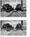
- wide field of view refers to an angle of more than 60°, measured in a horizontal plane, as shown in Fig. 3a and Fig. 3b .
- Such cameras with wide field of view are more demanded because they support better driving assistance systems, more information about the road context being provided to ADAS. For example, a pedestrian may not be detected by the camera if the field of view of the camera is less than or equal to 60° but may be detected if the field of view of the camera is more than 60° inclusively.
- Fig. 3a shows a schematic view of the field of view for which the stray light cover still has reasonable dimensions, namely around 50°.
- Fig. 3b shows a non-limiting example of wide field of view, of around 90°, which is more than 60°.
- polarization filters in the state of art to remove stray light has the disadvantage of requiring additional components such as a physical component to be placed within the camera and another component to switch on, respectively off the filter, said additional components being source of additional costs.
- the polarization filter has the disadvantage of attenuating the light that enters the camera, thus the images acquired are darker as compared with images taken in the absence of any polarization filter.
- the problem to be solved by the invention is how to remove window reflections on the images acquired by an ADAS camera, particularly in case ADAS camera has a wide field of view, without obstructing driver's field of view and without adding any new physical component, while ensuring that the removal of window reflections is more adaptive to sudden changes of outdoor luminous intensity and more adaptive to use of existing resources of the ego vehicle.
- the inventors conceived a method of removing stray light from an ego vehicle window in a camera arrangement comprising an exterior-facing camera configured to provide images to an advanced driving assistance system processing chain, said camera being mounted in the interior of the ego vehicle and facing said window, wherein the following repetitive sequence of steps is carried out:
- a camera arrangement mounted in the interior of a vehicle and facing at least one window of the vehicle, adapted to execute the steps of the method, said camera arrangement comprising:
- a computer program comprising instructions to cause the camera arrangement to execute the steps 1 and 4 of the method.
- a computer program comprising instructions to cause the camera arrangement to execute the steps 2, 3, 5, 6 and 7 of the method.
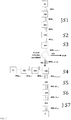
- a camera arrangement 1 comprising an exterior-facing camera 10 being mounted in the interior of the vehicle, facing any window W of the vehicle, configured to provide images to an advanced driving system ADAS processing chain 2.
- Said ADAS processing chain 2 may include, for example, functions of support of the image detection, functions of detection of the persons and objects from the road context, modelling functions for the road context, functions related to the safety such as braking and so on.
- the ADAS camera 10 comprises a lens barrel 100 where at least one lens is placed and a camera image sensor 101 which is configured to take images of the exterior of the vehicle and is further adapted to detect luminous intensity of outdoor light.
- the camera image sensor 101 is controlled by an image acquisition software component 102 that has double role.
- the first role is to set the parameters for the functioning of the camera image sensor 101, such as but not limited to: picture exposure time, region of interest, that is from what zones of the exterior of the vehicle should images be taken, what is the acquisition period of the pictures, etc.
- the second role of the image acquisition software component 102 is to acquire images from the camera image sensor 101 at a pre-determined acquisition rate that depends on the characteristics of the camera image sensor 101.
- the image acquisition software component 102 comprises a counter of the number n of acquired images incrementing with one unit after each acquired image.
- the ADAS camera 10 is further provided with an image pre-processing software component 104 having the role to carry out the processing of the images according to the steps of the method.
- Both image acquisition software component 102 and image pre-processing software component 104 use at least one memory component 103. All images acquired by the image acquisition software component 102 are temporary stored in the at least one memory 103, wherefrom they are used by the image pre-processing software component 104 for the purpose of carrying out the subsequent steps of the method. All images processed by the image pre-processing software component 104 are then stored in the at least one memory 103, wherefrom they can be used by the ADAS processing chain 2.
- the method consists of repetitive sequences of seven steps divided in two group of steps.
- the first group of steps of the method aims to identify an area of reflection in the raw images IMGn acquired by the image acquisition software component 102 and transmitted to the image pre-processing software component 104, while the second group of steps of the method aims to remove reflection identified in the previous group of steps, reason for which the second group of steps is carried out only if in the first step said area of reflection was identified.
- the word area stands for one area or a plurality of areas of the raw image IMGn entering the image pre-processing software component 104 for the purpose of carrying out the second group of steps.
- a raw image IMGn is acquired by the image acquisition software component 102 from the camera 10.
- the counter of the image acquisition software component 102 is incremented with one unit. Under certain conditions explained below, the counter may be reset to zero during the current trip of the ego vehicle.
- the raw image IMGn is sent by the software component 102 to the image pre-processing software component 104 by means of the at least one memory 103.
- one raw image IMGn is not sufficient, therefore for the purpose of accurately identification of the stray light, a number n of images is acquired, forming a plurality of raw images IMGn for the purpose of calculating an average of the luminous intensity in step 2 of the method.
- the number of raw images IMGn of the plurality of raw images IMGn depends on driving conditions, such as but not limited to: speed of the vehicle, change of the direction of the vehicle, differences of luminous intensity of outdoor light, etc.
- the average of the luminous intensity of each corresponding pixel of the acquired plurality comprising a number n of raw images IMGn carried out in step 2 has as result an average image AVGn.
- Said average image AVGn is updated continuously.
- a new average image AVGn+1 is calculated based on the preceding average image AVGn replacing it.
- one of the situations when permanent update of the average image AVGn is not convenient is the situation when the background and the luminous intensity of the pixels is changed due to the vehicle changes direction of driving. Therefore, whenever the yaw angle rate of ego vehicle is above a pre-determined yaw angle rate threshold, the counter of the acquisition software component 102 incrementing the number n of acquired raw images IMGn is reset to zero and a new plurality of images is used for calculating the average image AVGn.
- This sudden change may be expressed as a change of image luminous intensity taking place between during the last up to ten raw images IMGn of the time period for which the average image AVGn was calculated, provided that:
- the counter of the acquisition software component 102 incrementing the number n of acquired raw images IMGn is reset to zero and a new plurality of images is used for calculating the average image AVGn.
- Another situation when permanent update of the average image AVGn is not convenient is when the speed of ego vehicle is below a speed threshold, because the background change is slow and might be interpreted in the average image as reflection. In case the speed of the ego vehicle falls below said speed threshold, update of the average image is no longer carried out until the vehicle's speed exceeds said speed threshold.
- the average image AVGn remains equal to the last average of luminous intensity the average image AVGn-1 before the speed of the ego vehicle fell below said speed threshold, as long as the speed of the ego vehicle does not exceed said speed threshold or any of the other conditions related to said change of direction or said of change of luminous intensity or the combination of them that may reset the counter is, respectively are not met.
- the average image AVGn as calculated based on a plurality of raw images IMGn taken before each respective change, is not relevant immediately after the change, because the proportion of raw images IMGn used to calculate the average acquired before the change- thus showing the old stray light, is larger than the proportion of raw images IMGn acquired after the change- thus showing the new stray light.
- the new plurality of raw images AVGn By resetting the counter, the new plurality of raw images AVGn, based on which the future average images AVGn is to be calculated, will correspond to the new stray light occurred after the change of direction, change of luminous intensity or any combination of them.
- the reset of the counter of the image acquisition software component 102 to zero value has the advantage of making the method of the invention highly adaptive to a wide range of situations.
- the area of reflection is identified.
- Third step has two sub-steps: In the first sub-step of the third step, a filtering of the average image AVGn is carried out by a standard deviation filter sub-component 104-1 of the image pre-processing software component 104. For each pixel of the average image AVGn, the standard deviation value of the luminous intensity of the pixel in respect to the luminous intensity of its neighbourhood pixels is calculated.
- a pre-determined pixel standard deviation intensity threshold is used by the image pre-processing software component 104 for creating a binary image, said binary image forming a mask IMGn-wstrlight covering the area of reflection, said area of reflection identified by the pixels whose standard deviation luminous intensity luminous intensity of the average image AVGn is above said pixel standard deviation intensity threshold.
- the second group of steps of the method deals with removing of the reflection.
- an immediately subsequent raw image IMGn+1 to said plurality of raw images IMGn is acquired in step 4 of the method by the image acquisition software component 102 from the camera 10 and sent to the image pre-processing software component 104 by means of the at least one memory 103.
- This immediately subsequent raw image IMGn+1 is the image on which removal of reflection is carried out in step 5 of the method by a subtraction operated on each pixel of the reflection area previously identified.
- First weight of the luminous intensity expressed as a value comprised between 0 and 1 is dependent on the luminous intensity of the respective pixel of the immediately subsequent raw image IMGn+1. The more luminous the pixels of the immediately subsequent raw image IMGn+1, the greater the weight.
- the dependency between the first weight of the luminous intensity and the luminous intensity of the pixels is determined by experimental basis, and stored in the memory 102.
- the output of this step is the reflection-removed image IMG-Rn+1, having the reflection removed from the area of reflection.
- the areas corresponding to the reflection removed from the reflection-removed image IMG-Rn+1 are darker than the corresponding areas of said immediately subsequent raw image IMGn+1 before removal. These dark areas may be capable of impairing the quality of the image to be sent to the ADAS processing chain 2, reason for which another operation is required before making the image available to the ADAS processing chain 2.
- This operation is carried out in the sixth step of the method by means of the image pre-processing software component 104. It refers to compensating the loss of luminous intensity of the area of reflection of the reflection-removed image IMG-Rn+1. In order to do so, two sub-steps are required.
- a calculation of the average factor of the loss of luminous intensity of the area of reflection is made by of the immediately subsequent raw image IMGn+1 between the reflection-removed image IMG-Rn+1 and the area of reflection of the immediately subsequent raw image IMGn+1.
- the average factor of the loss of luminous intensity used in the compensation of the loss of luminous intensity is applied using either gamma correction, or uniformly or using a second weight of the luminous intensity for the compensation of loss of luminous intensity of all pixels of the area of reflection of the reflection-removed image IMG-Rn+1.
- the outcome of the sixth step is the corrected image with reflection removed and luminous intensity compensated IMG-Cn+1.
- This corrected image IMG-Cn+1 is temporary stored in the seventh step of the method in the at least one memory component 103 wherefrom it can be used by the ADAS processing chain 2.
- the inventors sought to make the method even more adaptive to various situations.
- the area of reflection identified in step 3 may have a non-convex shape with numerous irregularities that may, under certain conditions, lead to an unnecessary removal of reflection in step 4 creating irregular dark zones in the reflection-removed image IMG-Rn+1.
- a convex hull may be created by the image pre-processing software component 104 in an additional step 3.A. after the identification of the area of reflection in step 3. This has the advantage of avoiding excessive darkening of the reflection-removed image IMG-Rn+1, which in turn avoids excessive compensation needed in step 5.
- the actual size of the upper portion may be for example between the top half and the top third, the examples being for illustration only and not limiting the scope of the invention.
- top filtering step 3.1. is applied immediately before step 3 and the step of creating the convex hull 3.A. is applied immediately after step 3, the advantage being a better adaptation of the method of the invention to various situations arising from practice.
- the camera 10 is configured to face the windscreen of the ego vehicle for acquiring forward-facing images or the rear windscreen of the vehicle for acquiring rear-facing images or lateral windows for lateral-facing images.
- the camera 10 is configured to have a field of view of more than 60 ° measured in horizontal plane.
- an optimization of the pre-processing software component 104 may be desirable.
- optimizing the operation of the pre-processing software component 104 is carried out by training of an artificial neural network NN of the pre-processing software component 104 creating a set of constraints of said artificial neural network NN.
- the training may be carried out either off-line, or both off-line and online, in the latter case off-line training taking place before online training.
- Off-line training refers to sub-steps aiming to train the neural network NN of the pre-processing software component 104 before said the pre-processing software component 104 is ready to be operated, as this type of training is usually based on the results of tests carried out before said the pre-processing software component 104 is integrated into the camera arrangement 1.
- On-line training refers to sub-steps aiming to further train or fine-tune the neural network NN of the pre-processing software component 104 during the application of the method by the camera arrangement 1, as this type of training is based on actual and real-time data of applying said method.
- the camera arrangement 1 mounted in the interior of a vehicle and facing at least one window of the vehicle is adapted to execute the steps of the method.
- Said camera arrangement 1 comprises an advanced driver assistance systems ADAS camera 10 comprising a camera lens barrel 100 including at least one lens and a camera image sensor 101 configured to take images of the exterior of the vehicle and further configured to detect luminous intensity of outdoor light.
- ADAS camera 10 comprising a camera lens barrel 100 including at least one lens and a camera image sensor 101 configured to take images of the exterior of the vehicle and further configured to detect luminous intensity of outdoor light.
- Said camera arrangement 1 comprises an image acquisition software component 102 configured to acquire raw images IMGn from the camera image sensor 101.
- the image acquisition software component 102 comprises a counter counting the number n of acquired raw images, being further configured to set camera image sensor 101 parameters such as: picture exposure time, region of interest, acquisition period, and further configured to send acquired raw images IMGn to at least one memory component 103 in order to be used by an image pre-processing software component 104.
- the camera arrangement 1 comprises at least one memory 103, configured to temporary store the variables and parameters needed for the reflection removal, such as: the raw images IMGn, the average images AVGn, the average images AVGn comprising said mask IMGn-wstrlight, the reflection-removed images IMG-Rn+1, and corrected images with reflection removed and luminous intensity compensated IMG-Cn+1 and configured to store the number n of raw images IMGn of the plurality, the first weight used in step 5 of the method, the pixel standard deviation intensity threshold and configured to store the average factor.
- the variables and parameters needed for the reflection removal such as: the raw images IMGn, the average images AVGn, the average images AVGn comprising said mask IMGn-wstrlight, the reflection-removed images IMG-Rn+1, and corrected images with reflection removed and luminous intensity compensated IMG-Cn+1 and configured to store the number n of raw images IMGn of the plurality, the first weight used in step 5 of the method, the
- the camera arrangement 1 comprises the image pre-processing software component 104, configured to receive raw images IMGn from the acquisition software component 102 by means of the at least one memory 103, configured to calculate said average images AVGn, to create binary image forming a mask IMGn-wstrlight covering the area of reflection of said average images AVGn, to remove the reflection from the area of reflection of the immediately subsequent raw images IMGn+1 corresponding to said mask IMGn-wstrlight, to calculate of the average factor of the loss of luminous intensity, to compensate the loss of luminous intensity of the reflection-removed images IMG-Rn+1 and to send the corrected images with reflection removed and luminous intensity compensated IMG-Cn+1 to the at least one memory 103 be used by the advanced driving assistance system ADAS processing chain 2.
- a standard deviation filter sub-component 104-1 of the image pre-processing software component 104 of the camera arrangement is configured to carry out filtering of the average images AVGn
- the camera 10, the image acquisition software component 102, the image pre-processing software component 104 exist in the absence of the invention as well, providing images to the ADAS processing chain 2.
- the invention uses thus components that are already available in the setup of any modern vehicle by configuring each one of them to carry out the steps of the method.
- the combination of various embodiments of the invention has the advantage to adapt on to the multitude of practical situations when stray light needs to be correctly identified and removed and adapt to the characteristics of the components that exist in the ego vehicle.
- the memory 103 of the camera arrangement 1 may be in a preferred embodiment, further configured to store a pre-determined yaw angle rate threshold, and, in this case, the image acquisition software component 102 may be configured to reset to zero the counter and to use a new plurality of images for calculating the average image AVGn when the yaw angle rate of ego vehicle is above said pre-determined yaw angle rate threshold.
- the memory 103 of the camera arrangement 1 may be, in another preferred embodiment, further configured to store a pre-determined area percentage threshold, a pre-determined luminous intensity difference threshold and, in this case, the image acquisition software component 102 may be configured to reset to zero the said counter and to use a new plurality of a number n of raw images for calculating the average image AVGn when there is a change of image luminous intensity taking place during the last up to ten raw images IMGn of the period interval for which the average image AVGn was calculated, provided that:
- the memory 103 of the camera arrangement 1 may be, in another preferred embodiment, further configured to store a pre-determined speed threshold, and, in this case, the image acquisition software component 102 may be configured to use the average image AVGn of the last average of luminous intensity the average image AVGn-1 before the speed of the ego vehicle fell below said speed threshold.
- the image pre-processing software component 104 of the camera arrangement 1 may be, in another preferred embodiment, further configured to create the convex hull around the area of reflection identified in step 3 of the method.
- the image pre-processing software component 104 of the camera arrangement 1 may be, in another preferred embodiment, further configured to carry out the top area filtering step 3.1. that excludes a portion of the raw image IMGn situated at its top from the area reflection identification step 3.
- the image pre-processing software component 104 may further comprise an artificial neural network NN configured to be trained.
- two computer programs are further provided: one computer program for the image acquisition software component 102 and another computer program for the image processing software component 104.
- the computer program provided for the image acquisition software component 102 comprises instructions to cause the camera arrangement 1 to execute the step 1 and 4 of the method
- the computer program provided for the image processing software component 104 comprises instructions to cause the camera arrangement 1 to execute the steps 2,3,5,6 and 7 of the method as well as the additional steps immediately before or immediately after step 3, as described in the corresponding preferred embodiments.
- Fig. 1 shows an example of raw image IMGn containing the reflection.
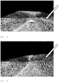
- Fig. 7a and Fig. 7b depict two examples of average image AVGn, corresponding to step 2 of the method.
- Fig. 7a depicts the average image AVGn calculated for the plurality of raw images IMGn acquired during 5s from the reset of the counter of the image acquisition software component 102
- Fig. 7b depicts the average image AVGn calculated for the plurality comprising a number n of raw images IMGn acquired during 30s from the reset of the image acquisition software component 102, including the first 5s.
- Fig. 8a , Fig. 9a and Fig. 10a illustrate the carrying out of step 3 of the method for the average image AVGn calculated for the plurality of raw images IMGn acquired during 5s from the reset of the counter of the image acquisition software component 102
- Fig. 8b , Fig. 9b and Fig. 10b illustrate the carrying out of step 3 of the method for the average image AVGn calculated for the plurality of raw images IMGn acquired during 30s from the reset of the counter of the image acquisition software component 102.
- Fig. 8 illustrates the output of the filtering of the average image AVGn after first sub-step of step 3
- Fig. 9 shows the filtered binary image created in the second sub-step of step 3
- Fig. 10 shows the masked image covering the area of reflection for all the pixels whose luminous intensity is above said pixel intensity threshold representing the output of the third step of the method, that is the average image comprising said mask IMGn-wstrlight.
- the convex hull is applied, as shown in Fig. 11a and Fig. 11b , where Fig. 11a illustrate the application of convex hull to the average image comprising said mask IMGn-wstrlight corresponding to incremental history of 5s from the reset of the counter of the image acquisition software component 102 and Fig. 11b illustrate the application of convex hull to the average image comprising said mask IMGn-wstrlight corresponding to incremental history of 30s from the reset of the counter of the image acquisition software component 102
- the second set of steps of the method starts with acquiring one immediately subsequent raw image IMGn+1 in step 4. This is shown in Fig. 12a - corresponding to the immediately subsequent raw image IMGn+1 after the first 5s of incremental history of the counter of the image acquisition software component 102, and in Fig. 12b - corresponding to the immediately subsequent raw image IMGn+1 after the first 30s of incremental history of the counter of the image acquisition software component 102, including the first 5s.
- step 5 of the method reflection is removed from the respective one immediately subsequent raw image IMGn+1, resulting the reflection-removed image IMG-Rn+1.
- step 6 of the method the reflection-removed image IMG-Rn+1 undergoes a compensation of the loss of luminous intensity, as the portion of the reflection-removed image IMG-Rn+1 corresponding to the area of reflection removed is darker after carrying out step 5 than it was before step 5.
- Compensation of the loss of luminous intensity is carried out in step 6 of the method, firstly by comparing the reflection-removed image reflection-removed image IMG-Rn+1 and the one immediately subsequent raw image IMGn+1 and calculating the average factor of the loss of luminous intensity. Then, using the average factor of the loss of luminous intensity, compensation of the loss of luminous intensity is made on the area of reflection of the reflection-removed image reflection-removed image IMG-Rn+1, either by gamma correction, or uniformly or using a second weight of the luminous intensity for the compensation of loss of luminous intensity of all pixels of the area of reflection of the reflection-removed image IMG-Rn+1.
- Fig. 13 shows the immediately subsequent raw image IMGn+1 after the first 5s of incremental history of the counter of the image acquisition software component 102: Fig. 13a illustrates reflection-removed image IMG-Rn+1 after completion of step 5 whereas Fig. 13b illustrates the corrected image with reflection removed and luminous intensity compensated IMG-Cn+1 after completion of step 6 of the method.
- Fig. 14a illustrates reflection-removed image IMG-Rn+1 after completion of step 5
- Fig. 14b illustrates the corrected image with reflection removed and luminous intensity compensated IMG-Cn+1 after completion of step 6 of the method.
- the corrected image with reflection removed and luminous intensity compensated IMG-Cn+1 is temporary stored in step 7 of the method in the at least one memory component 103, wherefrom they may be used by the advanced driving assistance system ADAS processing chain 2.
- the image acquisition software component 102 would have provided the advanced driving assistance system ADAS processing chain 2 with the immediately subsequent images IMGn+1 respectively illustrated in Fig. 12a and Fig. 12b .
- the corrected image with reflection removed and luminous intensity compensated IMG-Cn+1 illustrated in Fig. 13b replaces the one immediately subsequent image IMGn+1 of Fig. 12a and respectively the corrected image with reflection removed and luminous intensity compensated IMG-Cn+1 illustrated in Fig. 14b replaces the one immediately subsequent image IMGn+1 of Fig. 12b .
Landscapes
- Engineering & Computer Science (AREA)
- Physics & Mathematics (AREA)
- General Physics & Mathematics (AREA)
- Multimedia (AREA)
- Theoretical Computer Science (AREA)
- Image Processing (AREA)
Abstract
Description
- The invention is related to cameras used in advanced driver assistance systems processing chain, particularly in the field of removing window reflections on the images acquired by such camera mounted in the interior of a vehicle.
- Advanced driver assistance systems ADAS cameras, hereafter alternatively called cameras, are more and more used in automotive industry for the purpose to provide the advanced driver assistance systems processing chain with quick and accurate detection and recognize of objects and persons from the exterior of the vehicle such as other vehicles, pedestrians, obstacles, traffic signs, lane markers, etc. The information captured by cameras is then analysed by ADAS processing chain and used to trigger a response by the vehicle, being used for a wide range of functions, including for example: autonomous emergency braking AEB, lane departure warning LDW, lane keep assist, blind spot detection, night vision cameras and adaptive lighting, traffic sign recognition, parking assistance, etc.
- ADAS cameras are of various types, including for example: mono-cameras, stereo cameras, or surround view cameras.
- ADAS cameras are used for autonomous vehicles as well as for vehicles with human driver.
- Many ADAS cameras are windscreen-mounted facing forward. However, the ADAS camera may be mounted facing other windows of the vehicle in order to provide information from other areas of the exterior of said vehicle.
- In order to comply with the requirements of advanced driver assistance systems, the ADAS camera must have a field of view as clear as possible, ideally showing only exterior images.
- In reality, the images provided by the ADAS camera show not only the exterior of the vehicle, but also some amount of stray light.
- Stray light is used throughout this invention with the meaning of a light in an optical system, in this case the ADAS camera, which was not intended when said optical system was designed.
- In this invention, stray light takes the shape of reflections that appear on the window of the vehicle from various sources such as but not limited to objects of various colours placed within the vehicle. Stray light impedes the ADAS camera to take optimum quality pictures because the image provided by ADAS camera contains, apart from the screenshot of the exterior environment, a certain quantity of reflections, the quantity depending on various factors such as: intensity of outside light, materials and colours of the objects of the interior, dust, etc.
- Throughout this invention the terms stray light and reflection shall be used interchangeably.
- Other terms that shall be used interchangeably in this invention are: picture(s), shot(s), image(s), having the same meaning of picture(s) acquired by the ADAS camera.
- Yet another term used in this invention is ego vehicle designating the vehicle on whose window or windows stray light is disturbing and, for this reason, said stray light must be removed.
- The stray light disturbing the field of view or the quality of the pictures of ADAS camera may result in inaccurate assessment of the road context putting vehicles' and people' s safety at risk, because decision of the driver- human or automated is taken by using the information provided by various ADAS cameras of the vehicle.
-
Fig. 1 shows the image seen through a windscreen where the source of stray light is a flyer illustrated inFig. 2 placed on the dashboard of the ego vehicle. - As it can be seen in
Fig. 1 stray light is present in this example mainly in the lower left part and lower right part impeding a clear view of the vehicle positioned at the left of ego vehicle. - For this reason, stray light covers are being widely used in order to remove the stray light.
- An example of stray light cover is disclosed in
US 2019/0031117A1 published on 31 January 2019 . - Stray light covers are quite efficient in removing stray light, they manage to remove most of the reflections and they are of simple design that allows to customize different windscreen setups.
- Another method of removing stray light is by using a polarization filter.
- For example,
US 2017/0227791 discloses smart sunglasses, smart window and smart mirror for augmenting human vision by means of adaptive polarization filter grids.US 2017/0227791 is based on the fact that removing stray light-called glare in this patent, is carried out by making use of a grid of electrically configurable filters, said filters being in connection with a polarization sensor for capturing polarization characteristics of incident light and in connection with a polarization analyzer for analyzing polarization characteristics of incidental light and determining a target polarization filter state, said polarization filter state referring to angles of the grid element, such as disclosed in an embodiment 0°, 45°, 90° and 135°. - Smart window disclosed in
US 2017/0227791 makes use of the polarization filter states mainly with the purpose of adapting the elimination of the glare to the line of sight of each individual driver. - Other example of using a polarization filter is presented in
DE 102017202155 that discloses a camera system and a method of eliminating stray light. The method is based in using a camera or two cameras placed in a vehicle behind the windscreen, said camera(s) being provided with image evaluation unit. - The camera(s) take(s) several outer shots of an external environment of the vehicle and compare the shots by means of the image evaluation unit.
- The shots comprise static image components that correspond to the unwanted reflections, said static image components being recognized and extracted from the external shots by means of the image evaluation unit carrying image processing techniques.
- Use of stray light covers to remove stray light has a significant inconvenient in case of ADAS cameras with wide field of view. Throughout this invention, the term wide field of view refers to an angle of more than 60°, measured in a horizontal plane, as shown in
Fig. 3a and Fig. 3b . Such cameras with wide field of view are more demanded because they support better driving assistance systems, more information about the road context being provided to ADAS. For example, a pedestrian may not be detected by the camera if the field of view of the camera is less than or equal to 60° but may be detected if the field of view of the camera is more than 60° inclusively. - The inconvenient is that for an ADAS camera with the wide field of view, the stray light cover becomes so large that it obstructs a large portion of driver's field of view.
Fig. 3a shows a schematic view of the field of view for which the stray light cover still has reasonable dimensions, namely around 50°.Fig. 3b shows a non-limiting example of wide field of view, of around 90°, which is more than 60°. - Use of polarization filters in the state of art to remove stray light has the disadvantage of requiring additional components such as a physical component to be placed within the camera and another component to switch on, respectively off the filter, said additional components being source of additional costs. On the other side, the polarization filter has the disadvantage of attenuating the light that enters the camera, thus the images acquired are darker as compared with images taken in the absence of any polarization filter.
- The problem to be solved by the invention is how to remove window reflections on the images acquired by an ADAS camera, particularly in case ADAS camera has a wide field of view, without obstructing driver's field of view and without adding any new physical component, while ensuring that the removal of window reflections is more adaptive to sudden changes of outdoor luminous intensity and more adaptive to use of existing resources of the ego vehicle.
- In order to solve the problem, the inventors conceived a method of removing stray light from an ego vehicle window in a camera arrangement comprising an exterior-facing camera configured to provide images to an advanced driving assistance system processing chain, said camera being mounted in the interior of the ego vehicle and facing said window, wherein the following repetitive sequence of steps is carried out:
-
-
Step 1 Acquiring a raw image by an image acquisition software component from said camera and incrementing the number of acquired raw images as counted by a counter of the image acquisition software component with one unit, and sending the raw image to an image pre-processing software component by means of at least one memory; -
Step 2 Calculating, by means of the image pre-processing software component, for each corresponding pixel of a number of successive raw image forming a plurality of raw images, of an average of the luminous intensity, resulting an average image and where the number (n) of the raw images of said plurality depends on driving conditions, and sending the calculated average image to the at least one memory; -
Step 3 Identifying an area of reflection in the average image by means of the image pre-processing software component in two sub-steps:- in the first sub-step applying filtering for each pixel of the entire area of the average image by means of a standard deviation filter sub-component of the image pre-processing software component;
- in the second sub-step creating a binary image using a pre-determined pixel standard deviation intensity threshold, said binary image forming a mask covering the area of reflection, said area of reflection identified by the pixels whose standard deviation luminous intensity of the average image is above said pixel standard deviation intensity threshold,
- resulting an average image comprising said mask and sending it to the at least one memory,
-
-
Step 4 Acquiring by the image acquisition software component from said camera of an immediately subsequent raw image of said plurality and sending said immediately subsequent raw image to the image pre-processing software component by means of the at least one memory; -
Step 5 Removing by means of the image pre-processing software component the reflection from the area of reflection of the immediately subsequent raw image corresponding to said mask, by subtracting from the luminous intensity of each pixel of the area of reflection of the immediately subsequent raw image of a first weight of the luminous intensity of each corresponding pixel of said mask, where said first weight is dependent on the luminous intensity of the respective pixel of the immediately subsequent raw image,
resulting a reflection-removed image, and sending it to the at least one memory; -
Step 6 Compensating by means of the image pre-processing software component of the loss of luminous intensity of the area of reflection of the reflection-removed image, in two sub-steps:- in the first sub-step calculating of an average factor of the loss of luminous intensity between the area of reflection of the immediately subsequent raw image and the reflection-removed image;
- in the second sub-step using said average factor of the loss of luminous intensity for compensating the loss of luminous intensity of the area of reflection of the reflection-removed image;
-
Step 7 Temporary storing the corrected image with reflection removed and luminous intensity compensated in the at least one memory component, wherefrom said image with reflection removed and brightness restored can be used by the advanced driving assistance system processing chain. - In another aspect of the invention, it is provided a camera arrangement mounted in the interior of a vehicle and facing at least one window of the vehicle, adapted to execute the steps of the method, said camera arrangement comprising:
- an advanced driver assistance systems camera comprising a camera lens barrel including at least one lens and a camera image sensor configured to take images of the exterior of the vehicle and further configured to detect luminous intensity of outdoor light;
- an image acquisition software component, configured to acquire raw images from the camera image sensor and comprising a counter counting the number of acquired raw images, and further configured to set camera image sensor parameters such as: picture exposure time, region of interest, acquisition period, and further configured to send acquired raw images to at least one memory component in order to be used by an image pre-processing software component;
- at least one memory, configured to temporary store the variables and parameters needed for the reflection removal, such as: the raw images, the average images, the average images comprising said mask, reflection-removed images, and corrected images with reflection removed and luminous intensity compensated and the number n of raw images of the plurality, the first weight used in
step 5 of the method, the pixel standard deviation intensity threshold for creating a binary image forming a mask covering the area of reflection and the average factor; - the image pre-processing software component, configured to receive raw images from the acquisition software component by means of the at least one memory, configured to calculate said average images, to create binary images forming a mask covering the area of reflection of said average images, to remove the reflection from the area of reflection of the immediately subsequent raw images corresponding to said mask to calculate the average factor of the loss of luminous intensity, to compensate the loss of luminous intensity of the reflection-removed images and to send the corrected images with reflection removed and luminous intensity compensated to the at least one memory used by the advanced driving assistance system ADAS processing chain.
- a standard deviation filter sub-component of the image pre-processing software component configured to carry out filtering of the average images.
- In another aspect of the invention, it is provided a computer program comprising instructions to cause the camera arrangement to execute the
steps - In another aspect of the invention, it is provided a computer program comprising instructions to cause the camera arrangement to execute the
steps - The main advantages of this invention are the following:
- i) Method and camera arrangement according to the invention improve the quality of the images acquired by ADAS camera with field of view more than 60° by removing efficiently a significant amount of window reflections. Although method and camera arrangement according to the invention may be used for any angle of the field of view, it is particularly advantageous to use them for ADAS cameras having a wide field of view, typically of more than 60°.
- ii) Method and camera arrangement according to the invention are adaptable to any light conditions and in particular are suitable for use when sudden changes of luminous intensity of outdoor light is contemplated.
- iii) Method and camera arrangement according to the invention make use of current apparatus and electronic components existing on the vehicle, including: ADAS camera, micro-controllers, memory or memories etc.;
- iv) Method and camera arrangement according to the invention are suitable for use in the context of automated driving;
- v) Method and camera arrangement according to the invention do not obstruct driver's field of view;
- vi) Method and camera arrangement according to the invention, make efficient use of the computing resources of the camera arrangement;
-
-
Fig. 1 Example of stray light on the windscreen of the ego vehicle; -
Fig. 2 Flyer placed on the dashboard used as source of reflection; -
Fig. 3 Schematic view of the field of view FoV of the ADAS camera according to the invention as compared with prior art; -
Fig. 3a Schematic view of the field of view FoV of the ADAS camera using the stray light cover -50° FoV, as compared with a wide field of view FoV of the ADAS camera of more than 60°. -
Fig. 3b Schematic view of the field of view FoV of the ADAS camera using the method and the camera arrangement according to the invention -
Fig. 4 Camera arrangement according to the invention; -
Fig. 5 Block diagram of the method according to the invention; -
Fig. 6 Schematic view showing the principle of convex hull; -
Fig. 7-14 Example of realization:-
Fig. 7a The average image acquired after 5s incremental history; -
Fig. 7b The average image acquired after 30s incremental history; -
Fig. 8a Filtering of the average image acquired after 5s incremental history; -
Fig. 8b Filtering of the average image acquired after 30s incremental history; -
Fig. 9a Filtered binary image of the average image acquired after 5s incremental history; -
Fig. 9b Filtered binary image of the average image acquired after 30s incremental history; -
Fig. 10a Masked coloured image of the average image acquired after 5s incremental history; -
Fig. 10b Masked coloured image of the average image acquired after 30s incremental history; -
Fig. 11a Image masked with convex hull corresponding to the average image acquired after 5s incremental history; -
Fig. 11b Image masked with convex hull corresponding to the average image acquired after 30s incremental history; -
Fig. 12a Immediately subsequent raw image corresponding to the immediately subsequent raw image after the first 5s of incremental history; -
Fig. 12b Immediately subsequent raw image corresponding to the immediately subsequent raw image after the first 30s of incremental history; -
Fig. 13a Image showing the reflection-removed image corresponding to the immediately subsequent raw image after the first 5s of incremental history; -
Fig. 13b Image showing the corrected image with reflection removed and luminous intensity compensated corresponding to the immediately subsequent raw image after the first 5s of incremental history; -
Fig. 14a Image showing the reflection-removed image corresponding to the immediately subsequent raw image after the first 30 s of incremental history; -
Fig. 14b Image showing the corrected image with reflection removed and luminous intensity compensated corresponding to the immediately subsequent raw image after the first 30 s of incremental history.
-
-
- 1 Camera arrangement
- 2 ADAS Processing Chain
- 10 Exterior-facing Camera
- 100 Camera Lens Barrel
- 101 Camera Image Sensor
- 102 Image acquisition software component
- 103 At least one memory component
- 104 Image pre-processing software component
- 104-1 Standard deviation filter sub-component of the image pre-processing software component
- FoV Field of view of the
camera 10 - With reference to
Fig. 4 , the method is carried out in acamera arrangement 1 according to the invention, comprising an exterior-facingcamera 10 being mounted in the interior of the vehicle, facing any window W of the vehicle, configured to provide images to an advanced driving systemADAS processing chain 2. SaidADAS processing chain 2 may include, for example, functions of support of the image detection, functions of detection of the persons and objects from the road context, modelling functions for the road context, functions related to the safety such as braking and so on. - With reference to
Fig. 4 , theADAS camera 10 comprises alens barrel 100 where at least one lens is placed and acamera image sensor 101 which is configured to take images of the exterior of the vehicle and is further adapted to detect luminous intensity of outdoor light. - The
camera image sensor 101 is controlled by an imageacquisition software component 102 that has double role. The first role is to set the parameters for the functioning of thecamera image sensor 101, such as but not limited to: picture exposure time, region of interest, that is from what zones of the exterior of the vehicle should images be taken, what is the acquisition period of the pictures, etc. The second role of the imageacquisition software component 102 is to acquire images from thecamera image sensor 101 at a pre-determined acquisition rate that depends on the characteristics of thecamera image sensor 101. The imageacquisition software component 102 comprises a counter of the number n of acquired images incrementing with one unit after each acquired image. - The
ADAS camera 10 is further provided with an imagepre-processing software component 104 having the role to carry out the processing of the images according to the steps of the method. - Both image
acquisition software component 102 and imagepre-processing software component 104 use at least onememory component 103. All images acquired by the imageacquisition software component 102 are temporary stored in the at least onememory 103, wherefrom they are used by the imagepre-processing software component 104 for the purpose of carrying out the subsequent steps of the method. All images processed by the imagepre-processing software component 104 are then stored in the at least onememory 103, wherefrom they can be used by theADAS processing chain 2. - With reference to
Fig. 5 , according to the invention, the method consists of repetitive sequences of seven steps divided in two group of steps. - The first group of steps of the method aims to identify an area of reflection in the raw images IMGn acquired by the image
acquisition software component 102 and transmitted to the imagepre-processing software component 104, while the second group of steps of the method aims to remove reflection identified in the previous group of steps, reason for which the second group of steps is carried out only if in the first step said area of reflection was identified. - The word area stands for one area or a plurality of areas of the raw image IMGn entering the image
pre-processing software component 104 for the purpose of carrying out the second group of steps. - In the first step of the method, a raw image IMGn is acquired by the image
acquisition software component 102 from thecamera 10. - Each time a raw image IMGn is acquired by the
software component 102 after the engine is turned on, the counter of the imageacquisition software component 102 is incremented with one unit. Under certain conditions explained below, the counter may be reset to zero during the current trip of the ego vehicle. - The raw image IMGn is sent by the
software component 102 to the imagepre-processing software component 104 by means of the at least onememory 103. - In order to accurately identify reflection, one raw image IMGn is not sufficient, therefore for the purpose of accurately identification of the stray light, a number n of images is acquired, forming a plurality of raw images IMGn for the purpose of calculating an average of the luminous intensity in
step 2 of the method. - The number of raw images IMGn of the plurality of raw images IMGn depends on driving conditions, such as but not limited to: speed of the vehicle, change of the direction of the vehicle, differences of luminous intensity of outdoor light, etc.
- The average of the luminous intensity of each corresponding pixel of the acquired plurality comprising a number n of raw images IMGn carried out in
step 2 has as result an average image AVGn. - Said average image AVGn is updated continuously. When an immediately subsequent raw image IMGn+1 enters into the plurality of images, a new average image AVGn+1 is calculated based on the preceding average image AVGn replacing it.
- In a preferred embodiment, the average image AVGn of the luminous intensity of the plurality of raw images IMGn is calculated as a mathematical average using the formula:

- Permanent update of the average image AVGn may not be convenient in some driving situations as described below.
- In another preferred embodiment, one of the situations when permanent update of the average image AVGn is not convenient, is the situation when the background and the luminous intensity of the pixels is changed due to the vehicle changes direction of driving. Therefore, whenever the yaw angle rate of ego vehicle is above a pre-determined yaw angle rate threshold, the counter of the
acquisition software component 102 incrementing the number n of acquired raw images IMGn is reset to zero and a new plurality of images is used for calculating the average image AVGn. - In another preferred embodiment, when permanent update of the average image AVGn is not convenient, is the situation when there is a sudden change of the luminous intensity.
- This sudden change may be expressed as a change of image luminous intensity taking place between during the last up to ten raw images IMGn of the time period for which the average image AVGn was calculated, provided that:
- there is a change of image luminous intensity in a percentage of the area of the raw images IMGn over a pre-determined area percentage threshold; and
- the respective area affected by the change of image luminous intensity has a difference of luminous intensity over a pre-determined luminous intensity difference threshold.
- Therefore, whenever a sudden change of luminous intensity occurs, the counter of the
acquisition software component 102 incrementing the number n of acquired raw images IMGn is reset to zero and a new plurality of images is used for calculating the average image AVGn. - Yet another preferred embodiment, another situation when permanent update of the average image AVGn is not convenient, is when the speed of ego vehicle is below a speed threshold, because the background change is slow and might be interpreted in the average image as reflection. In case the speed of the ego vehicle falls below said speed threshold, update of the average image is no longer carried out until the vehicle's speed exceeds said speed threshold.
- Therefore, if the speed of the ego vehicle is below a speed threshold, the average image AVGn remains equal to the last average of luminous intensity the average image AVGn-1 before the speed of the ego vehicle fell below said speed threshold, as long as the speed of the ego vehicle does not exceed said speed threshold or any of the other conditions related to said change of direction or said of change of luminous intensity or the combination of them that may reset the counter is, respectively are not met.
- For all the above-referenced situations of change of direction, change of luminous intensity, or combination of them, the average image AVGn, as calculated based on a plurality of raw images IMGn taken before each respective change, is not relevant immediately after the change, because the proportion of raw images IMGn used to calculate the average acquired before the change- thus showing the old stray light, is larger than the proportion of raw images IMGn acquired after the change- thus showing the new stray light.
- By resetting the counter, the new plurality of raw images AVGn, based on which the future average images AVGn is to be calculated, will correspond to the new stray light occurred after the change of direction, change of luminous intensity or any combination of them. The reset of the counter of the image
acquisition software component 102 to zero value has the advantage of making the method of the invention highly adaptive to a wide range of situations. - In the third step of the method, the area of reflection is identified. Third step has two sub-steps:
In the first sub-step of the third step, a filtering of the average image AVGn is carried out by a standard deviation filter sub-component 104-1 of the imagepre-processing software component 104. For each pixel of the average image AVGn, the standard deviation value of the luminous intensity of the pixel in respect to the luminous intensity of its neighbourhood pixels is calculated. - Then, in the second sub-step of the third step, a pre-determined pixel standard deviation intensity threshold is used by the image
pre-processing software component 104 for creating a binary image, said binary image forming a mask IMGn-wstrlight covering the area of reflection, said area of reflection identified by the pixels whose standard deviation luminous intensity luminous intensity of the average image AVGn is above said pixel standard deviation intensity threshold. - If no pixel shows standard deviation intensity above said pixel standard deviation intensity threshold, there is no reflection to be removed.
- In case there are pixels whose standard deviation intensity is above said pixel standard deviation intensity threshold, they are contained in the mask IMGn-wstrlight.
- The second group of steps of the method deals with removing of the reflection. To this end, an immediately subsequent raw image IMGn+1 to said plurality of raw images IMGn is acquired in
step 4 of the method by the imageacquisition software component 102 from thecamera 10 and sent to the imagepre-processing software component 104 by means of the at least onememory 103. - This immediately subsequent raw image IMGn+1 is the image on which removal of reflection is carried out in
step 5 of the method by a subtraction operated on each pixel of the reflection area previously identified. The subtraction can be represented schematically as follows:
- First weight of the luminous intensity, expressed as a value comprised between 0 and 1 is dependent on the luminous intensity of the respective pixel of the immediately subsequent raw
image IMGn+ 1. The more luminous the pixels of the immediately subsequent rawimage IMGn+ 1, the greater the weight. - The dependency between the first weight of the luminous intensity and the luminous intensity of the pixels is determined by experimental basis, and stored in the
memory 102. - The output of this step is the reflection-removed image IMG-Rn+1, having the reflection removed from the area of reflection.
- After having removed the stray light from the immediately subsequent raw
image IMGn+ 1, the areas corresponding to the reflection removed from the reflection-removed image IMG-Rn+1are darker than the corresponding areas of said immediately subsequent raw image IMGn+1 before removal. These dark areas may be capable of impairing the quality of the image to be sent to theADAS processing chain 2, reason for which another operation is required before making the image available to theADAS processing chain 2. - This operation is carried out in the sixth step of the method by means of the image
pre-processing software component 104. It refers to compensating the loss of luminous intensity of the area of reflection of the reflection-removed image IMG-Rn+ 1. In order to do so, two sub-steps are required. - In the first sub-step of the sixth step, a calculation of the average factor of the loss of luminous intensity of the area of reflection is made by of the immediately subsequent raw image IMGn+1 between the reflection-removed image IMG-
Rn+ 1 and the area of reflection of the immediately subsequent rawimage IMGn+ 1. - Then, using said average factor of the loss of luminous intensity, in the second sub-step of the sixth step, using said average factor of the loss of luminous intensity is carried out for compensating the loss of luminous intensity of the area of reflection of the reflection-removed image IMG-
Rn+ 1. - In a preferred embodiment, the average factor of the loss of luminous intensity used in the compensation of the loss of luminous intensity is applied using either gamma correction, or uniformly or using a second weight of the luminous intensity for the compensation of loss of luminous intensity of all pixels of the area of reflection of the reflection-removed image IMG-
Rn+ 1. - The choice between the types of compensation depend on which one provides better compensation results. This is another way of making the method of the invention more adaptive to various situations.
- The outcome of the sixth step is the corrected image with reflection removed and luminous intensity compensated IMG-
Cn+ 1. This corrected image IMG-Cn+ 1 is temporary stored in the seventh step of the method in the at least onememory component 103 wherefrom it can be used by theADAS processing chain 2. - The inventors sought to make the method even more adaptive to various situations.
- One example of fine tuning of the method is presented in another preferred embodiment. The inventors noticed that in some cases, the area of reflection identified in
step 3 may have a non-convex shape with numerous irregularities that may, under certain conditions, lead to an unnecessary removal of reflection instep 4 creating irregular dark zones in the reflection-removed image IMG-Rn+ 1. To remedy this, a convex hull may be created by the imagepre-processing software component 104 in an additional step 3.A. after the identification of the area of reflection instep 3. This has the advantage of avoiding excessive darkening of the reflection-removed image IMG-Rn+1, which in turn avoids excessive compensation needed instep 5. - Yet another example of fine tuning of the method is presented in another preferred embodiment, being based on the observation that in most of the cases stray light does not affect the top portion of the raw image IMGn.
- The actual size of the upper portion may be for example between the top half and the top third, the examples being for illustration only and not limiting the scope of the invention.
- In such cases, it is convenient to exclude the top part of the raw image IMGn from the application of the method and carry out the method only in respect to the remainder of the raw image IMGn. This is done in an additional step immediately before
step 3, in a top filtering step 3.1. that excludes a portion of the raw image IMGn situated at its top from the reflectionarea identification step 3. - It is possible to combine the embodiments when top filtering step 3.1. is applied immediately before
step 3 and the step of creating the convex hull 3.A. is applied immediately afterstep 3, the advantage being a better adaptation of the method of the invention to various situations arising from practice. - In another preferred embodiment of the invention that may be combined with any of the preceding preferred embodiments, the
camera 10 is configured to face the windscreen of the ego vehicle for acquiring forward-facing images or the rear windscreen of the vehicle for acquiring rear-facing images or lateral windows for lateral-facing images. - In another preferred embodiment of the invention the
camera 10 is configured to have a field of view of more than 60 ° measured in horizontal plane. - Given the complexity of the real-life situation in which the method is carried out, an optimization of the
pre-processing software component 104 may be desirable. - In another preferred embodiment of the invention that in its turn may be combined with any of the preceding preferred embodiments optimizing the operation of the
pre-processing software component 104 is carried out by training of an artificial neural network NN of thepre-processing software component 104 creating a set of constraints of said artificial neural network NN. - The training may be carried out either off-line, or both off-line and online, in the latter case off-line training taking place before online training.
- Off-line training refers to sub-steps aiming to train the neural network NN of the
pre-processing software component 104 before said thepre-processing software component 104 is ready to be operated, as this type of training is usually based on the results of tests carried out before said thepre-processing software component 104 is integrated into thecamera arrangement 1. - On-line training refers to sub-steps aiming to further train or fine-tune the neural network NN of the
pre-processing software component 104 during the application of the method by thecamera arrangement 1, as this type of training is based on actual and real-time data of applying said method. - The
camera arrangement 1 mounted in the interior of a vehicle and facing at least one window of the vehicle is adapted to execute the steps of the method. - Said
camera arrangement 1 comprises an advanced driver assistancesystems ADAS camera 10 comprising acamera lens barrel 100 including at least one lens and acamera image sensor 101 configured to take images of the exterior of the vehicle and further configured to detect luminous intensity of outdoor light. - Said
camera arrangement 1 comprises an imageacquisition software component 102 configured to acquire raw images IMGn from thecamera image sensor 101. The imageacquisition software component 102 comprises a counter counting the number n of acquired raw images, being further configured to setcamera image sensor 101 parameters such as: picture exposure time, region of interest, acquisition period, and further configured to send acquired raw images IMGn to at least onememory component 103 in order to be used by an imagepre-processing software component 104. - The
camera arrangement 1 comprises at least onememory 103, configured to temporary store the variables and parameters needed for the reflection removal, such as: the raw images IMGn, the average images AVGn, the average images AVGn comprising said mask IMGn-wstrlight, the reflection-removed images IMG-Rn+1, and corrected images with reflection removed and luminous intensity compensated IMG-Cn+ 1 and configured to store the number n of raw images IMGn of the plurality, the first weight used instep 5 of the method, the pixel standard deviation intensity threshold and configured to store the average factor. - The
camera arrangement 1 comprises the imagepre-processing software component 104, configured to receive raw images IMGn from theacquisition software component 102 by means of the at least onememory 103, configured to calculate said average images AVGn, to create binary image forming a mask IMGn-wstrlight covering the area of reflection of said average images AVGn, to remove the reflection from the area of reflection of the immediately subsequent raw images IMGn+1 corresponding to said mask IMGn-wstrlight, to calculate of the average factor of the loss of luminous intensity, to compensate the loss of luminous intensity of the reflection-removed images IMG-Rn+ 1 and to send the corrected images with reflection removed and luminous intensity compensated IMG-Cn+1 to the at least onememory 103 be used by the advanced driving assistance systemADAS processing chain 2. - A standard deviation filter sub-component 104-1 of the image
pre-processing software component 104 of the camera arrangement is configured to carry out filtering of the average images AVGn - The
camera 10, the imageacquisition software component 102, the imagepre-processing software component 104 exist in the absence of the invention as well, providing images to theADAS processing chain 2. - The invention uses thus components that are already available in the setup of any modern vehicle by configuring each one of them to carry out the steps of the method. The combination of various embodiments of the invention has the advantage to adapt on to the multitude of practical situations when stray light needs to be correctly identified and removed and adapt to the characteristics of the components that exist in the ego vehicle.
- The
memory 103 of thecamera arrangement 1 may be in a preferred embodiment, further configured to store a pre-determined yaw angle rate threshold, and, in this case, the imageacquisition software component 102 may be configured to reset to zero the counter and to use a new plurality of images for calculating the average image AVGn when the yaw angle rate of ego vehicle is above said pre-determined yaw angle rate threshold. - The
memory 103 of thecamera arrangement 1 may be, in another preferred embodiment, further configured to store a pre-determined area percentage threshold, a pre-determined luminous intensity difference threshold and, in this case, the imageacquisition software component 102 may be configured to reset to zero the said counter and to use a new plurality of a number n of raw images for calculating the average image AVGn when there is a change of image luminous intensity taking place during the last up to ten raw images IMGn of the period interval for which the average image AVGn was calculated, provided that: - there is a change of image luminous intensity in a percentage of the area of the raw images IMGn over said pre-determined area percentage threshold and
- the respective area affected by the change of image luminous intensity has a difference of luminous intensity over said pre-determined luminous intensity difference threshold.
- The
memory 103 of thecamera arrangement 1 may be, in another preferred embodiment, further configured to store a pre-determined speed threshold, and, in this case, the imageacquisition software component 102 may be configured to use the average image AVGn of the last average of luminous intensity the average image AVGn-1 before the speed of the ego vehicle fell below said speed threshold. - The image
pre-processing software component 104 of thecamera arrangement 1 may be, in another preferred embodiment, further configured to create the convex hull around the area of reflection identified instep 3 of the method. - The image
pre-processing software component 104 of thecamera arrangement 1 may be, in another preferred embodiment, further configured to carry out the top area filtering step 3.1. that excludes a portion of the raw image IMGn situated at its top from the areareflection identification step 3. - If optimization of the operation of the image
pre-processing software component 104 is sought, in another preferred embodiment, the imagepre-processing software component 104 may further comprise an artificial neural network NN configured to be trained. - In order to apply the method of the invention, two computer programs are further provided: one computer program for the image
acquisition software component 102 and another computer program for the imageprocessing software component 104. - The computer program provided for the image
acquisition software component 102 comprises instructions to cause thecamera arrangement 1 to execute thestep processing software component 104 comprises instructions to cause thecamera arrangement 1 to execute thesteps step 3, as described in the corresponding preferred embodiments. - The example of realization, referring to drawings of
Fig. 1, Fig 2 . and Figs. from 7 to 14, is used to better illustrate the method of the invention and refers to one of the possible combinations of the embodiments of the invention. - This example shall not be considered as limiting the working of the invention only to this combination of the embodiments. For this purpose, all examples of values given below shall be considered for illustration of the technical teaching of the invention and not for limiting the scope of the invention to the values mentioned.
- In this example:
- the window is the windscreen, however it may equally be the rear window or any of the lateral windows;
- the method uses the mathematical average of the luminous intensity of the plurality of raw image IMGn, it includes the additional step 3.A. of creating the convex hull but does not include top area filtering;
- the acquisition rate of the
camera image sensor 101 is at 30 fps (frames/per/second), thus the sequence of images is perceived as a video; - the driving scenario is straight driving and no change of direction;
- for comparative exemplification, two intervals for the incremental history of the counter of the image
acquisition software component 102 were considered: 5s and 30s. - As seen in
Fig. 1 and Fig. 2 a flyer was placed on the dashboard of the ego vehicle as source of reflection.Fig. 1 shows an example of raw image IMGn containing the reflection. -
Fig. 7a and Fig. 7b depict two examples of average image AVGn, corresponding to step 2 of the method.Fig. 7a depicts the average image AVGn calculated for the plurality of raw images IMGn acquired during 5s from the reset of the counter of the imageacquisition software component 102, whileFig. 7b depicts the average image AVGn calculated for the plurality comprising a number n of raw images IMGn acquired during 30s from the reset of the imageacquisition software component 102, including the first 5s. - Comparing
Fig. 7a withFig. 7b , one can see that the reflection is better emphasized in the average image AVGn taken after 30s as compared to the average image AVGn taken after 5s, as some of the artefacts, such as parked cars, moving cars in front fromFig. 7a ) are no longer present inFig. 7b . Since any average image AVGn contains context as background and reflection as foreground, a longer incremental history helps emphasize better the reflection that is roughly constant over the time of the incremental history.Fig. 8 ,Fig. 9 andFig. 10 illustratestep 3 of the method for corresponding to creating a binary image using a pre-determined pixel standard deviation intensity threshold, said binary image forming a mask IMGn-wstrlight covering the area of reflection by the pixels whose luminous intensity of the average image AVGn is above pixel standard deviation intensity threshold. -
Fig. 8a ,Fig. 9a andFig. 10a illustrate the carrying out ofstep 3 of the method for the average image AVGn calculated for the plurality of raw images IMGn acquired during 5s from the reset of the counter of the imageacquisition software component 102, whereasFig. 8b ,Fig. 9b andFig. 10b illustrate the carrying out ofstep 3 of the method for the average image AVGn calculated for the plurality of raw images IMGn acquired during 30s from the reset of the counter of the imageacquisition software component 102. -
Fig. 8 illustrates the output of the filtering of the average image AVGn after first sub-step ofstep 3,Fig. 9 shows the filtered binary image created in the second sub-step ofstep 3 andFig. 10 shows the masked image covering the area of reflection for all the pixels whose luminous intensity is above said pixel intensity threshold representing the output of the third step of the method, that is the average image comprising said mask IMGn-wstrlight. - In this example of realization, after determining the area of reflection through the masked image that concludes the
step 3 of the method, the convex hull is applied, as shown inFig. 11a and Fig. 11b , whereFig. 11a illustrate the application of convex hull to the average image comprising said mask IMGn-wstrlight corresponding to incremental history of 5s from the reset of the counter of the imageacquisition software component 102 andFig. 11b illustrate the application of convex hull to the average image comprising said mask IMGn-wstrlight corresponding to incremental history of 30s from the reset of the counter of the imageacquisition software component 102 - The second set of steps of the method starts with acquiring one immediately subsequent raw image IMGn+1 in
step 4. This is shown inFig. 12a - corresponding to the immediately subsequent raw image IMGn+1 after the first 5s of incremental history of the counter of the imageacquisition software component 102, and inFig. 12b - corresponding to the immediately subsequent raw image IMGn+1 after the first 30s of incremental history of the counter of the imageacquisition software component 102, including the first 5s. - Then, in
step 5 of the method, reflection is removed from the respective one immediately subsequent rawimage IMGn+ 1, resulting the reflection-removed image IMG-Rn+ 1. - Further on, in
step 6 of the method, the reflection-removed image IMG-Rn+ 1 undergoes a compensation of the loss of luminous intensity, as the portion of the reflection-removed image IMG-Rn+ 1 corresponding to the area of reflection removed is darker after carrying outstep 5 than it was beforestep 5. - Compensation of the loss of luminous intensity is carried out in
step 6 of the method, firstly by comparing the reflection-removed image reflection-removed image IMG-Rn+ 1 and the one immediately subsequent raw image IMGn+1 and calculating the average factor of the loss of luminous intensity. Then, using the average factor of the loss of luminous intensity, compensation of the loss of luminous intensity is made on the area of reflection of the reflection-removed image reflection-removed image IMG-Rn+1, either by gamma correction, or uniformly or using a second weight of the luminous intensity for the compensation of loss of luminous intensity of all pixels of the area of reflection of the reflection-removed image IMG-Rn+ 1. - To illustrate the effect of the correction by compensation of the loss of luminous intensity,
Fig. 13 shows the immediately subsequent raw image IMGn+1 after the first 5s of incremental history of the counter of the image acquisition software component 102:Fig. 13a illustrates reflection-removed image IMG-Rn+ 1 after completion ofstep 5 whereasFig. 13b illustrates the corrected image with reflection removed and luminous intensity compensated IMG-Cn+ 1 after completion ofstep 6 of the method. - The same comparative illustration of the effect of correction by compensation of the loss of luminous intensity corresponding to the immediately subsequent raw image IMGn+1 after the first 30s of incremental history of the counter of the image
acquisition software component 102 is shown inFig. 14: Fig. 14a illustrates reflection-removed image IMG-Rn+ 1 after completion ofstep 5 whereasFig. 14b illustrates the corrected image with reflection removed and luminous intensity compensated IMG-Cn+ 1 after completion ofstep 6 of the method. - The corrected image with reflection removed and luminous intensity compensated IMG-
Cn+ 1 is temporary stored instep 7 of the method in the at least onememory component 103, wherefrom they may be used by the advanced driving assistance systemADAS processing chain 2. - In the absence of the invention, the image
acquisition software component 102 would have provided the advanced driving assistance systemADAS processing chain 2 with the immediately subsequent images IMGn+1 respectively illustrated inFig. 12a and Fig. 12b . - By applying the method of the invention in this example of realization, the corrected image with reflection removed and luminous intensity compensated IMG-
Cn+ 1 illustrated inFig. 13b replaces the one immediately subsequent image IMGn+1 ofFig. 12a and respectively the corrected image with reflection removed and luminous intensity compensated IMG-Cn+ 1 illustrated inFig. 14b replaces the one immediately subsequent image IMGn+1 ofFig. 12b . - By comparing
Fig. 12a withFig. 13b and, respectively theFig. 12b withFig. 14b , it can be seen that the corrected images with reflection removed and luminous intensity compensated IMG-Cn+1 as shown inFig. 13b andFig. 14b provided to the advanced driving assistance systemADAS processing chain 2 contain less reflection than the respective raw images IMGn+1 illustrated inFig. 12a and, respectivelyFig. 12b , which means that the problem of the invention was solved. - While the description of the method and the camera arrangement system was disclosed in detail in connection to preferred embodiments, those skilled in the art will appreciate that changes may be made to adapt a particular situation without departing from the essential scope to the teaching of the invention.
Claims (21)
- Method of removing stray light from an ego vehicle window in a camera arrangement (1) comprising an exterior-facing camera (10) configured to provide images to an advanced driving assistance system (ADAS) processing chain (2), said camera (10) being mounted in the interior of the ego vehicle and facing said window, wherein the following repetitive sequence of steps is carried out:First group of steps: Identification of area of reflectionStep 1 Acquiring a raw image (IMGn) by an image acquisition software component (102) from said camera (10) and incrementing the number (n) of acquired raw images as counted by a counter of the image acquisition software component (102) with one unit, and sending the raw image (IMGn) to an image pre-processing software component (104) by means of at least one memory (103);Step 2 Calculating, by means of the image pre-processing software component (104), for each corresponding pixel of a number (n) of successive raw images (IMGn) forming a plurality of raw images (IMGn) of an average of the luminous intensity, resulting an average image (AVGn) and where the number (n) of the raw images (IMGn) of said plurality depends on driving conditions and sending the calculated average image (AVGn) to the at least one memory (103);Step 3 Identifying an area of reflection in the average image (AVGn) by means of the image pre-processing software component (104) in two sub-steps:- in the first sub-step applying filtering for each pixel of the entire area of the average image (AVGn) by means of a standard deviation filter sub-component (104-1) of the image pre-processing software component (104);- in the second sub-step creating a binary image using a pre-determined pixel standard deviation intensity threshold, said binary image forming a mask (IMGn-wstrlight) covering the area of reflection, said area of reflection identified by the pixels whose standard deviation luminous intensity of the average image (AVGn) is above said pixel standard deviation intensity threshold;resulting an average image (AVGn) comprising said mask (IMGn-wstrlight) and sending it to the at least one memory (103) ;Second group of steps: Reflection removalStep 4 Acquiring by the image acquisition software component (102) from said camera (10) of an immediately subsequent raw image (IMGn+1) of said plurality and sending said immediately subsequent raw image (IMGn+1) to the image pre-processing software component (104) by means of the at least one memory (103);Step 5 Removing by means of the image pre-processing software component (104) the reflection from the area of reflection of the immediately subsequent raw image (IMGn+1) corresponding to said mask (IMGn-wstrlight), by subtracting from the luminous intensity of each pixel of the area of reflection of the immediately subsequent raw image (IMGn+1) of a first weight of the luminous intensity of each corresponding pixel of said mask (IMGn-wstrlight), where said first weight is dependent on the luminous intensity of the respective pixel of the immediately subsequent raw image (IMGn+1),
resulting a reflection-removed image (IMG-Rn+1) and sending it to the at least one memory (103);Step 6 Compensating by means of the image pre-processing software component (104) of the loss of luminous intensity of the area of reflection of the reflection-removed image (IMG-Rn+1), in two sub-steps:- in the first sub-step calculating of an average factor of the loss of luminous intensity between the area of reflection of the immediately subsequent raw image (IMGn+1) and the reflection-removed image (IMG-Rn+1);- in the second sub-step using said average factor of the loss of luminous intensity for compensating the loss of luminous intensity of the area of reflection of the reflection-removed image (IMG-Rn+1);resulting a corrected image with reflection removed and luminous intensity compensated (IMG-Cn+1);Step 7 Temporary storing the corrected image with reflection removed and luminous intensity compensated (IMG-Cn+1) in the at least one memory component (103) wherefrom said image with reflection removed and brightness restored can be used by the advanced driving assistance system ADAS processing chain (2). - Method according to claim 1, wherein the average image (AVGn) of the luminous intensity of the plurality is calculated as a mathematical average using the formula:

- Method according to claim 1 or 2, wherein when the yaw angle rate of ego vehicle is above a pre-determined yaw angle rate threshold, the said counter of the acquisition software component (102) incrementing the number (n) of acquired raw images (IMGn) is reset to zero and a new plurality is used for calculating the average image (AVGn).
- Method according to any of the claims 1 to 3, wherein said counter of the acquisition software component (102) is reset to zero and a new plurality is used for calculating the average image (AVGn) when there is a change of image luminous intensity taking place during the last period of up to ten raw images (IMGn) of the time period for which the average image (AVGn) was calculated, provided that:- there is a change of image luminous intensity in a percentage of the area of the raw images (IMGn) over a pre-determined area percentage threshold; and- the respective area affected by the change of image luminous intensity has a difference of luminous intensity over a pre-determined luminous intensity difference threshold.
- Method according to any of the claims 1 to 4, wherein if the speed of the ego vehicle is below a speed threshold, the average image (AVGn) remains equal to the last average of luminous intensity the average image (AVGn-1) before the speed of the ego vehicle fell below said speed threshold, as long as the speed of the ego vehicle does not exceed said speed threshold.
- Method according to any of the claims 1 to 5, wherein the average factor of the loss of luminous intensity used in the compensation of the loss of luminous intensity is applied using either gamma correction, or uniformly or using a second weight of the luminous intensity for the compensation of loss of luminous intensity of all pixels of the area of reflection of the reflection-removed image (IMG-Rn+1).
- Method according to any of the claims 1 to 6, wherein the first group of steps may include, after the identification of area of reflection in step 3, a new step 3.A. of creating a convex hull around the area of reflection.
- Method according to any of the claims 1 to 6, wherein the first group of steps may include, before the identification of area of reflection in step 3, a top area filtering step 3.1. that excludes a portion of the raw image (IMGn) situated at its top from the area reflection identification step.
- Method according to claims 7 and 8, wherein the first group of steps may include the step of top area filtering 3.1. before the identification of area of reflection in step 3, and may include the step 3.A. of creating the convex hull after the identification of area of reflection in step 3.
- Method according to any of the preceding claims wherein the camera (10) is configured to face the windscreen of the ego vehicle for acquiring forward-facing images or the rear windscreen of the vehicle for acquiring rear-facing images or lateral windows for lateral-facing images.
- Method according to any of the preceding claims wherein the camera (10) is configured to have a field of view of more than 60 ° measured in horizontal plane.
- Method according to any of the preceding claims, for optimizing the operation of the pre-processing software component (104), wherein the method or steps of the method is or, respectively are performed by training of an artificial neural network (NN) of the pre-processing software component (104) creating a set of constraints of said artificial neural network (NN) .
- Camera arrangement (1) mounted in the interior of a vehicle and facing at least one window of the vehicle, adapted to execute the steps of the method according to claims 1 to 12 comprising:- an advanced driver assistance systems (ADAS) camera (10) comprising a camera lens barrel (100) including at least one lens and a camera image sensor (101) configured to take images of the exterior of the vehicle and further configured to detect luminous intensity of outdoor light;- an image acquisition software component (102), configured to acquire raw images (IMGn) from the camera image sensor (101) and comprising a counter counting the number (n) of acquired raw images, and further configured to set camera image sensor (101) parameters such as: picture exposure time, region of interest, acquisition period, and further configured to send acquired raw images (IMGn) to at least one memory component (103) in order to be used by an image pre-processing software component (104);- at least one memory (103), configured to temporary store the variables and parameters needed for the reflection removal, such as: the raw images (IMGn), the average images (AVGn), the average images (AVGn) comprising said mask (IMGn-wstrlight), the reflection-removed images (IMG-Rn+1) corrected images with reflection removed and luminous intensity compensated (IMG-Cn+1), the number (n) of raw images (IMGn) of the plurality, the first weight used in step 5 of the method, the pixel standard deviation intensity threshold for creating a binary image forming a mask (IMGn-wstrlight) covering the area of reflection and the average factor;.- the image pre-processing software component (104), configured to receive raw images (IMGn) from the acquisition software component (102) by means of the at least one memory (103), configured to calculate said average images (AVGn), to create binary images forming a mask (IMGn-wstrlight) covering the area of reflection of said average images (AVGn), to remove the reflection from the area of reflection of the immediately subsequent raw images (IMGn+1) corresponding to said mask (IMGn-wstrlight), to calculate of the average factor of the loss of luminous intensity, to compensate the loss of luminous intensity of the reflection-removed images (IMG-Rn+1) and to send the corrected images with reflection removed and luminous intensity compensated (IMG-Cn+1) to the at least one memory (103) be used by the advanced driving assistance system ADAS processing chain (2).- a standard deviation filter sub-component (104-1) of the image pre-processing software component (104) configured to carry out filtering of the average images (AVGn).
- Camera arrangement (1) according to claim 13, wherein the at least one memory (103) is further configured to store a pre-determined yaw angle rate threshold, and the image acquisition software component (102) is configured to reset to zero the said counter and to use a new plurality for calculating the average image (AVGn) when the yaw angle rate of ego vehicle is above said pre-determined yaw angle rate threshold.
- Camera arrangement (1) according to claim 13 or 14, wherein the at least one memory (103) is further configured to store a pre-determined area percentage threshold, a pre-determined luminous intensity difference threshold and the image acquisition software component (102) is configured to reset to zero the said counter, and to use a new plurality for calculating the average image (AVGn) when the conditions provided in claim 4 are fulfilled.
- Camera arrangement (1) according to any of the claims 13 to 15, wherein the at least one memory (103) is further configured to store a pre-determined speed threshold, and the image acquisition software component (102) is configured to use the average image (AVGn) of the last average of luminous intensity the average image (AVGn-1) before the speed of the ego vehicle fell below said speed threshold.
- Camera arrangement (1) according to any of the claims claim 13 to 16, wherein the image pre-processing software component (104) is further configured to create in step 3.A. a convex hull around the area of reflection.
- Camera arrangement (1) according to claim 13 to 16, wherein the image pre-processing software component (104) is further configured to perform the top area filtering step 3.1.
- Camera arrangement (1) according to any of the claims 13 to 18, wherein said pre-processing software component (104) further comprises an artificial neural network (NN) configured to be trained according to the claim 12 of the method.
- A computer program comprising instructions to cause the camera arrangement (1) of any of the claims 13 to 18 to execute steps 1 and 4 of the method according to any of the claims 1 to 12.
- A computer program comprising instructions to cause the camera arrangement (1) of any of the claims 13 to 18 to execute the steps 2, 3, 5 6 and 7 of the method according to any of the claims 1 to 12, including the additional steps 3.A. and 3.1.
Priority Applications (1)
| Application Number | Priority Date | Filing Date | Title |
|---|---|---|---|
| EP19465546.0A EP3783526B1 (en) | 2019-08-22 | 2019-08-22 | Method of removing stray light from an ego vehicle window in a camera arrangement, camera arrangement and computer program for applying said method |
Applications Claiming Priority (1)
| Application Number | Priority Date | Filing Date | Title |
|---|---|---|---|
| EP19465546.0A EP3783526B1 (en) | 2019-08-22 | 2019-08-22 | Method of removing stray light from an ego vehicle window in a camera arrangement, camera arrangement and computer program for applying said method |
Publications (2)
| Publication Number | Publication Date |
|---|---|
| EP3783526A1 true EP3783526A1 (en) | 2021-02-24 |
| EP3783526B1 EP3783526B1 (en) | 2023-12-06 |
Family
ID=67997557
Family Applications (1)
| Application Number | Title | Priority Date | Filing Date |
|---|---|---|---|
| EP19465546.0A Active EP3783526B1 (en) | 2019-08-22 | 2019-08-22 | Method of removing stray light from an ego vehicle window in a camera arrangement, camera arrangement and computer program for applying said method |
Country Status (1)
| Country | Link |
|---|---|
| EP (1) | EP3783526B1 (en) |
Citations (4)
| Publication number | Priority date | Publication date | Assignee | Title |
|---|---|---|---|---|
| US20170227791A1 (en) | 2016-05-19 | 2017-08-10 | Maximilian Ralph Peter von und zu Liechtenstein | Smart sunglasses, smart window and smart mirror apparatus for augmenting human vision by means of adaptive polarization filter grids |
| DE102017202155A1 (en) | 2017-02-10 | 2018-08-16 | Conti Temic Microelectronic Gmbh | Camera system for a vehicle |
| WO2018197763A1 (en) * | 2017-04-25 | 2018-11-01 | Continental Automotive France | Image-processing method for removing light zones |
| US20190031117A1 (en) | 2011-04-20 | 2019-01-31 | Magna Electronics Inc. | Vehicle vision system with windshield mounted camera |
-
2019
- 2019-08-22 EP EP19465546.0A patent/EP3783526B1/en active Active
Patent Citations (4)
| Publication number | Priority date | Publication date | Assignee | Title |
|---|---|---|---|---|
| US20190031117A1 (en) | 2011-04-20 | 2019-01-31 | Magna Electronics Inc. | Vehicle vision system with windshield mounted camera |
| US20170227791A1 (en) | 2016-05-19 | 2017-08-10 | Maximilian Ralph Peter von und zu Liechtenstein | Smart sunglasses, smart window and smart mirror apparatus for augmenting human vision by means of adaptive polarization filter grids |
| DE102017202155A1 (en) | 2017-02-10 | 2018-08-16 | Conti Temic Microelectronic Gmbh | Camera system for a vehicle |
| WO2018197763A1 (en) * | 2017-04-25 | 2018-11-01 | Continental Automotive France | Image-processing method for removing light zones |
Non-Patent Citations (4)
| Title |
|---|
| JUN YOUNG CHEONG ET AL: "Reflection Removal Under Fast Forward Camera Motion", IEEE TRANSACTIONS ON IMAGE PROCESSING, vol. 26, no. 12, 1 September 2017 (2017-09-01), US, pages 6061 - 6073, XP055665343, ISSN: 1057-7149, DOI: 10.1109/TIP.2017.2748389 * |
| REINHARD E. ET AL.: "Color transfer between images", IEEE COMPUTER GRAPHICS AND APPLICATIONS, vol. 21, no. 5, 1 September 2001 (2001-09-01), pages 34 - 41, XP055011470, ISSN: 0272-1716, DOI: 10.1109/38.946629 * |
| SIMON CHRISTIAN ET AL: "Reflection removal for in-vehicle black box videos", 2015 IEEE CONFERENCE ON COMPUTER VISION AND PATTERN RECOGNITION (CVPR), IEEE, 7 June 2015 (2015-06-07), pages 4231 - 4239, XP032793877, DOI: 10.1109/CVPR.2015.7299051 * |
| V. KUDVA ET AL: "Detection of Specular Reflection and Segmentation of Cervix Region in Uterine Cervix Images for Cervical Cancer Screening", IRBM, vol. 38, no. 5, 15 September 2017 (2017-09-15), AMSTERDAM, NL, pages 281 - 291, XP055665353, ISSN: 1959-0318, DOI: 10.1016/j.irbm.2017.08.003 * |
Also Published As
| Publication number | Publication date |
|---|---|
| EP3783526B1 (en) | 2023-12-06 |
Similar Documents
| Publication | Publication Date | Title |
|---|---|---|
| EP2821960A1 (en) | Method for identification of contamination upon a lens of a stereoscopic camera | |
| EP3149656B1 (en) | Detection, identification, and mitigation of lens contamination for vehicle mounted camera systems | |
| EP2558336B1 (en) | Method and device for assisting a driver while driving a vehicle by detecting weather-related visibility limitations | |
| US20180232587A1 (en) | Vehicle monitoring method and apparatus, processor, and image acquisition device | |
| DE102020215860A1 (en) | Correction of images from an all-round view camera system in the event of rain, light and dirt | |
| EP2723060A1 (en) | Vehicle-mounted camera device | |
| DE102020215859A1 (en) | Correction of images from a camera in rain, light and dirt | |
| CN110135235B (en) | Glare processing method and device and vehicle | |
| EP3115930A1 (en) | Malfunction diagnosis apparatus | |
| EP2583847A1 (en) | Device and method for reducing glare | |
| CN117325804A (en) | Automatic defogging method, device, equipment and medium for camera | |
| CN119963452B (en) | An electronic rearview mirror image defogging method based on image information integration | |
| CN110672335A (en) | Method and device for judging failure of lane keeping auxiliary function | |
| DE102018216983B3 (en) | Method for suppressing images of reflections in at least one camera image of a camera of an environmental sensor device of a motor vehicle and corresponding environment sensor device | |
| EP3696722A1 (en) | Method of removing stray light from a vehicle window in a camera arrangement, camera arrangement for using said method and computer programs | |
| DE102016221123A1 (en) | Method and device for operating a display system with data glasses | |
| EP3856557A1 (en) | Method for detecting light conditions in a vehicle | |
| EP3783526B1 (en) | Method of removing stray light from an ego vehicle window in a camera arrangement, camera arrangement and computer program for applying said method | |
| DE102015216993A1 (en) | Improved process for recording a scene, especially in a critical exposure situation | |
| CN117079085B (en) | Training method of raindrop detection model, vehicle control method, device and medium | |
| JP2018074191A (en) | In-vehicle image display system, in-vehicle image display method, and program | |
| TWI630818B (en) | Dynamic image feature enhancement method and system | |
| US20200195856A1 (en) | Method and Device for Improving Camera Images for Driver Assistance Systems | |
| CN112243089B (en) | Camera HDR image effect switch control method, device, rearview mirror, vehicle and storage medium | |
| DE102017206247A1 (en) | Method for predictive exposure control of a vehicle camera |
Legal Events
| Date | Code | Title | Description |
|---|---|---|---|
| PUAI | Public reference made under article 153(3) epc to a published international application that has entered the european phase |
Free format text: ORIGINAL CODE: 0009012 |
|
| STAA | Information on the status of an ep patent application or granted ep patent |
Free format text: STATUS: THE APPLICATION HAS BEEN PUBLISHED |
|
| AK | Designated contracting states |
Kind code of ref document: A1 Designated state(s): AL AT BE BG CH CY CZ DE DK EE ES FI FR GB GR HR HU IE IS IT LI LT LU LV MC MK MT NL NO PL PT RO RS SE SI SK SM TR |
|
| AX | Request for extension of the european patent |
Extension state: BA ME |
|
| STAA | Information on the status of an ep patent application or granted ep patent |
Free format text: STATUS: REQUEST FOR EXAMINATION WAS MADE |
|
| 17P | Request for examination filed |
Effective date: 20210824 |
|
| RBV | Designated contracting states (corrected) |
Designated state(s): AL AT BE BG CH CY CZ DE DK EE ES FI FR GB GR HR HU IE IS IT LI LT LU LV MC MK MT NL NO PL PT RO RS SE SI SK SM TR |
|
| RAP1 | Party data changed (applicant data changed or rights of an application transferred) |
Owner name: CONTINENTAL AUTONOMOUS MOBILITY GERMANY GMBH |
|
| STAA | Information on the status of an ep patent application or granted ep patent |
Free format text: STATUS: EXAMINATION IS IN PROGRESS |
|
| 17Q | First examination report despatched |
Effective date: 20230213 |
|
| REG | Reference to a national code |
Ref country code: DE Free format text: PREVIOUS MAIN CLASS: G06K0009000000 Ref country code: DE Ref legal event code: R079 Ref document number: 602019042744 Country of ref document: DE Free format text: PREVIOUS MAIN CLASS: G06K0009000000 Ipc: G06V0020560000 |
|
| GRAP | Despatch of communication of intention to grant a patent |
Free format text: ORIGINAL CODE: EPIDOSNIGR1 |
|
| STAA | Information on the status of an ep patent application or granted ep patent |
Free format text: STATUS: GRANT OF PATENT IS INTENDED |
|
| RIC1 | Information provided on ipc code assigned before grant |
Ipc: G06V 10/50 20220101ALI20230621BHEP Ipc: G06V 10/30 20220101ALI20230621BHEP Ipc: G06V 20/56 20220101AFI20230621BHEP |
|
| INTG | Intention to grant announced |
Effective date: 20230706 |
|
| GRAS | Grant fee paid |
Free format text: ORIGINAL CODE: EPIDOSNIGR3 |
|
| GRAA | (expected) grant |
Free format text: ORIGINAL CODE: 0009210 |
|
| STAA | Information on the status of an ep patent application or granted ep patent |
Free format text: STATUS: THE PATENT HAS BEEN GRANTED |
|
| AK | Designated contracting states |
Kind code of ref document: B1 Designated state(s): AL AT BE BG CH CY CZ DE DK EE ES FI FR GB GR HR HU IE IS IT LI LT LU LV MC MK MT NL NO PL PT RO RS SE SI SK SM TR |
|
| REG | Reference to a national code |
Ref country code: GB Ref legal event code: FG4D |
|
| REG | Reference to a national code |
Ref country code: CH Ref legal event code: EP |
|
| REG | Reference to a national code |
Ref country code: DE Ref legal event code: R096 Ref document number: 602019042744 Country of ref document: DE |
|
| REG | Reference to a national code |
Ref country code: IE Ref legal event code: FG4D |
|
| REG | Reference to a national code |
Ref country code: LT Ref legal event code: MG9D |
|
| PG25 | Lapsed in a contracting state [announced via postgrant information from national office to epo] |
Ref country code: GR Free format text: LAPSE BECAUSE OF FAILURE TO SUBMIT A TRANSLATION OF THE DESCRIPTION OR TO PAY THE FEE WITHIN THE PRESCRIBED TIME-LIMIT Effective date: 20240307 |
|
| REG | Reference to a national code |
Ref country code: NL Ref legal event code: MP Effective date: 20231206 |
|
| PG25 | Lapsed in a contracting state [announced via postgrant information from national office to epo] |
Ref country code: LT Free format text: LAPSE BECAUSE OF FAILURE TO SUBMIT A TRANSLATION OF THE DESCRIPTION OR TO PAY THE FEE WITHIN THE PRESCRIBED TIME-LIMIT Effective date: 20231206 |
|
| PG25 | Lapsed in a contracting state [announced via postgrant information from national office to epo] |
Ref country code: ES Free format text: LAPSE BECAUSE OF FAILURE TO SUBMIT A TRANSLATION OF THE DESCRIPTION OR TO PAY THE FEE WITHIN THE PRESCRIBED TIME-LIMIT Effective date: 20231206 |
|
| PG25 | Lapsed in a contracting state [announced via postgrant information from national office to epo] |
Ref country code: LT Free format text: LAPSE BECAUSE OF FAILURE TO SUBMIT A TRANSLATION OF THE DESCRIPTION OR TO PAY THE FEE WITHIN THE PRESCRIBED TIME-LIMIT Effective date: 20231206 Ref country code: GR Free format text: LAPSE BECAUSE OF FAILURE TO SUBMIT A TRANSLATION OF THE DESCRIPTION OR TO PAY THE FEE WITHIN THE PRESCRIBED TIME-LIMIT Effective date: 20240307 Ref country code: ES Free format text: LAPSE BECAUSE OF FAILURE TO SUBMIT A TRANSLATION OF THE DESCRIPTION OR TO PAY THE FEE WITHIN THE PRESCRIBED TIME-LIMIT Effective date: 20231206 Ref country code: BG Free format text: LAPSE BECAUSE OF FAILURE TO SUBMIT A TRANSLATION OF THE DESCRIPTION OR TO PAY THE FEE WITHIN THE PRESCRIBED TIME-LIMIT Effective date: 20240306 |
|
| REG | Reference to a national code |
Ref country code: AT Ref legal event code: MK05 Ref document number: 1639149 Country of ref document: AT Kind code of ref document: T Effective date: 20231206 |
|
| PG25 | Lapsed in a contracting state [announced via postgrant information from national office to epo] |
Ref country code: NL Free format text: LAPSE BECAUSE OF FAILURE TO SUBMIT A TRANSLATION OF THE DESCRIPTION OR TO PAY THE FEE WITHIN THE PRESCRIBED TIME-LIMIT Effective date: 20231206 |
|
| PG25 | Lapsed in a contracting state [announced via postgrant information from national office to epo] |
Ref country code: SE Free format text: LAPSE BECAUSE OF FAILURE TO SUBMIT A TRANSLATION OF THE DESCRIPTION OR TO PAY THE FEE WITHIN THE PRESCRIBED TIME-LIMIT Effective date: 20231206 Ref country code: RS Free format text: LAPSE BECAUSE OF FAILURE TO SUBMIT A TRANSLATION OF THE DESCRIPTION OR TO PAY THE FEE WITHIN THE PRESCRIBED TIME-LIMIT Effective date: 20231206 Ref country code: NO Free format text: LAPSE BECAUSE OF FAILURE TO SUBMIT A TRANSLATION OF THE DESCRIPTION OR TO PAY THE FEE WITHIN THE PRESCRIBED TIME-LIMIT Effective date: 20240306 Ref country code: NL Free format text: LAPSE BECAUSE OF FAILURE TO SUBMIT A TRANSLATION OF THE DESCRIPTION OR TO PAY THE FEE WITHIN THE PRESCRIBED TIME-LIMIT Effective date: 20231206 Ref country code: LV Free format text: LAPSE BECAUSE OF FAILURE TO SUBMIT A TRANSLATION OF THE DESCRIPTION OR TO PAY THE FEE WITHIN THE PRESCRIBED TIME-LIMIT Effective date: 20231206 Ref country code: HR Free format text: LAPSE BECAUSE OF FAILURE TO SUBMIT A TRANSLATION OF THE DESCRIPTION OR TO PAY THE FEE WITHIN THE PRESCRIBED TIME-LIMIT Effective date: 20231206 |
|
| PG25 | Lapsed in a contracting state [announced via postgrant information from national office to epo] |
Ref country code: IS Free format text: LAPSE BECAUSE OF FAILURE TO SUBMIT A TRANSLATION OF THE DESCRIPTION OR TO PAY THE FEE WITHIN THE PRESCRIBED TIME-LIMIT Effective date: 20240406 |
|
| PG25 | Lapsed in a contracting state [announced via postgrant information from national office to epo] |
Ref country code: AT Free format text: LAPSE BECAUSE OF FAILURE TO SUBMIT A TRANSLATION OF THE DESCRIPTION OR TO PAY THE FEE WITHIN THE PRESCRIBED TIME-LIMIT Effective date: 20231206 Ref country code: CZ Free format text: LAPSE BECAUSE OF FAILURE TO SUBMIT A TRANSLATION OF THE DESCRIPTION OR TO PAY THE FEE WITHIN THE PRESCRIBED TIME-LIMIT Effective date: 20231206 |
|
| PG25 | Lapsed in a contracting state [announced via postgrant information from national office to epo] |
Ref country code: SK Free format text: LAPSE BECAUSE OF FAILURE TO SUBMIT A TRANSLATION OF THE DESCRIPTION OR TO PAY THE FEE WITHIN THE PRESCRIBED TIME-LIMIT Effective date: 20231206 |
|
| PG25 | Lapsed in a contracting state [announced via postgrant information from national office to epo] |
Ref country code: SM Free format text: LAPSE BECAUSE OF FAILURE TO SUBMIT A TRANSLATION OF THE DESCRIPTION OR TO PAY THE FEE WITHIN THE PRESCRIBED TIME-LIMIT Effective date: 20231206 Ref country code: SK Free format text: LAPSE BECAUSE OF FAILURE TO SUBMIT A TRANSLATION OF THE DESCRIPTION OR TO PAY THE FEE WITHIN THE PRESCRIBED TIME-LIMIT Effective date: 20231206 Ref country code: RO Free format text: LAPSE BECAUSE OF FAILURE TO SUBMIT A TRANSLATION OF THE DESCRIPTION OR TO PAY THE FEE WITHIN THE PRESCRIBED TIME-LIMIT Effective date: 20231206 Ref country code: IT Free format text: LAPSE BECAUSE OF FAILURE TO SUBMIT A TRANSLATION OF THE DESCRIPTION OR TO PAY THE FEE WITHIN THE PRESCRIBED TIME-LIMIT Effective date: 20231206 Ref country code: IS Free format text: LAPSE BECAUSE OF FAILURE TO SUBMIT A TRANSLATION OF THE DESCRIPTION OR TO PAY THE FEE WITHIN THE PRESCRIBED TIME-LIMIT Effective date: 20240406 Ref country code: EE Free format text: LAPSE BECAUSE OF FAILURE TO SUBMIT A TRANSLATION OF THE DESCRIPTION OR TO PAY THE FEE WITHIN THE PRESCRIBED TIME-LIMIT Effective date: 20231206 Ref country code: CZ Free format text: LAPSE BECAUSE OF FAILURE TO SUBMIT A TRANSLATION OF THE DESCRIPTION OR TO PAY THE FEE WITHIN THE PRESCRIBED TIME-LIMIT Effective date: 20231206 Ref country code: AT Free format text: LAPSE BECAUSE OF FAILURE TO SUBMIT A TRANSLATION OF THE DESCRIPTION OR TO PAY THE FEE WITHIN THE PRESCRIBED TIME-LIMIT Effective date: 20231206 |
|
| PG25 | Lapsed in a contracting state [announced via postgrant information from national office to epo] |
Ref country code: PT Free format text: LAPSE BECAUSE OF FAILURE TO SUBMIT A TRANSLATION OF THE DESCRIPTION OR TO PAY THE FEE WITHIN THE PRESCRIBED TIME-LIMIT Effective date: 20240408 Ref country code: PL Free format text: LAPSE BECAUSE OF FAILURE TO SUBMIT A TRANSLATION OF THE DESCRIPTION OR TO PAY THE FEE WITHIN THE PRESCRIBED TIME-LIMIT Effective date: 20231206 |
|
| PG25 | Lapsed in a contracting state [announced via postgrant information from national office to epo] |
Ref country code: PT Free format text: LAPSE BECAUSE OF FAILURE TO SUBMIT A TRANSLATION OF THE DESCRIPTION OR TO PAY THE FEE WITHIN THE PRESCRIBED TIME-LIMIT Effective date: 20240408 Ref country code: PL Free format text: LAPSE BECAUSE OF FAILURE TO SUBMIT A TRANSLATION OF THE DESCRIPTION OR TO PAY THE FEE WITHIN THE PRESCRIBED TIME-LIMIT Effective date: 20231206 |
|
| REG | Reference to a national code |
Ref country code: DE Ref legal event code: R097 Ref document number: 602019042744 Country of ref document: DE |
|
| PG25 | Lapsed in a contracting state [announced via postgrant information from national office to epo] |
Ref country code: DK Free format text: LAPSE BECAUSE OF FAILURE TO SUBMIT A TRANSLATION OF THE DESCRIPTION OR TO PAY THE FEE WITHIN THE PRESCRIBED TIME-LIMIT Effective date: 20231206 |
|
| PLBE | No opposition filed within time limit |
Free format text: ORIGINAL CODE: 0009261 |
|
| STAA | Information on the status of an ep patent application or granted ep patent |
Free format text: STATUS: NO OPPOSITION FILED WITHIN TIME LIMIT |
|
| PG25 | Lapsed in a contracting state [announced via postgrant information from national office to epo] |
Ref country code: SI Free format text: LAPSE BECAUSE OF FAILURE TO SUBMIT A TRANSLATION OF THE DESCRIPTION OR TO PAY THE FEE WITHIN THE PRESCRIBED TIME-LIMIT Effective date: 20231206 |
|
| PG25 | Lapsed in a contracting state [announced via postgrant information from national office to epo] |
Ref country code: SI Free format text: LAPSE BECAUSE OF FAILURE TO SUBMIT A TRANSLATION OF THE DESCRIPTION OR TO PAY THE FEE WITHIN THE PRESCRIBED TIME-LIMIT Effective date: 20231206 Ref country code: DK Free format text: LAPSE BECAUSE OF FAILURE TO SUBMIT A TRANSLATION OF THE DESCRIPTION OR TO PAY THE FEE WITHIN THE PRESCRIBED TIME-LIMIT Effective date: 20231206 |
|
| 26N | No opposition filed |
Effective date: 20240909 |
|
| REG | Reference to a national code |
Ref country code: CH Ref legal event code: PL |
|
| PG25 | Lapsed in a contracting state [announced via postgrant information from national office to epo] |
Ref country code: LU Free format text: LAPSE BECAUSE OF NON-PAYMENT OF DUE FEES Effective date: 20240822 |
|
| GBPC | Gb: european patent ceased through non-payment of renewal fee |
Effective date: 20240822 |
|
| PG25 | Lapsed in a contracting state [announced via postgrant information from national office to epo] |
Ref country code: MC Free format text: LAPSE BECAUSE OF FAILURE TO SUBMIT A TRANSLATION OF THE DESCRIPTION OR TO PAY THE FEE WITHIN THE PRESCRIBED TIME-LIMIT Effective date: 20231206 Ref country code: CH Free format text: LAPSE BECAUSE OF NON-PAYMENT OF DUE FEES Effective date: 20240831 |
|
| REG | Reference to a national code |
Ref country code: BE Ref legal event code: MM Effective date: 20240831 |
|
| PG25 | Lapsed in a contracting state [announced via postgrant information from national office to epo] |
Ref country code: GB Free format text: LAPSE BECAUSE OF NON-PAYMENT OF DUE FEES Effective date: 20240822 |
|
| REG | Reference to a national code |
Ref country code: DE Ref legal event code: R081 Ref document number: 602019042744 Country of ref document: DE Owner name: AUMOVIO AUTONOMOUS MOBILITY GERMANY GMBH, DE Free format text: FORMER OWNER: CONTINENTAL AUTONOMOUS MOBILITY GERMANY GMBH, 85057 INGOLSTADT, DE |
|
| PG25 | Lapsed in a contracting state [announced via postgrant information from national office to epo] |
Ref country code: BE Free format text: LAPSE BECAUSE OF NON-PAYMENT OF DUE FEES Effective date: 20240831 |
|
| PG25 | Lapsed in a contracting state [announced via postgrant information from national office to epo] |
Ref country code: FR Free format text: LAPSE BECAUSE OF NON-PAYMENT OF DUE FEES Effective date: 20240831 |
|
| PG25 | Lapsed in a contracting state [announced via postgrant information from national office to epo] |
Ref country code: IE Free format text: LAPSE BECAUSE OF NON-PAYMENT OF DUE FEES Effective date: 20240822 |
|
| PG25 | Lapsed in a contracting state [announced via postgrant information from national office to epo] |
Ref country code: FI Free format text: LAPSE BECAUSE OF FAILURE TO SUBMIT A TRANSLATION OF THE DESCRIPTION OR TO PAY THE FEE WITHIN THE PRESCRIBED TIME-LIMIT Effective date: 20231207 |
|
| PGFP | Annual fee paid to national office [announced via postgrant information from national office to epo] |
Ref country code: DE Payment date: 20250831 Year of fee payment: 7 |
|
| PG25 | Lapsed in a contracting state [announced via postgrant information from national office to epo] |
Ref country code: CY Free format text: LAPSE BECAUSE OF FAILURE TO SUBMIT A TRANSLATION OF THE DESCRIPTION OR TO PAY THE FEE WITHIN THE PRESCRIBED TIME-LIMIT; INVALID AB INITIO Effective date: 20190822 |
|
| PG25 | Lapsed in a contracting state [announced via postgrant information from national office to epo] |
Ref country code: HU Free format text: LAPSE BECAUSE OF FAILURE TO SUBMIT A TRANSLATION OF THE DESCRIPTION OR TO PAY THE FEE WITHIN THE PRESCRIBED TIME-LIMIT; INVALID AB INITIO Effective date: 20190822 |
|
| PG25 | Lapsed in a contracting state [announced via postgrant information from national office to epo] |
Ref country code: TR Free format text: LAPSE BECAUSE OF FAILURE TO SUBMIT A TRANSLATION OF THE DESCRIPTION OR TO PAY THE FEE WITHIN THE PRESCRIBED TIME-LIMIT Effective date: 20231206 |