EP3783361A1 - Sampling tool for lubricating fluid analysis - Google Patents
Sampling tool for lubricating fluid analysis Download PDFInfo
- Publication number
- EP3783361A1 EP3783361A1 EP20191917.2A EP20191917A EP3783361A1 EP 3783361 A1 EP3783361 A1 EP 3783361A1 EP 20191917 A EP20191917 A EP 20191917A EP 3783361 A1 EP3783361 A1 EP 3783361A1
- Authority
- EP
- European Patent Office
- Prior art keywords
- tank
- port
- engine
- lubrication fluid
- sampling
- Prior art date
- Legal status (The legal status is an assumption and is not a legal conclusion. Google has not performed a legal analysis and makes no representation as to the accuracy of the status listed.)
- Granted
Links
Images




Classifications
-
- G—PHYSICS
- G01—MEASURING; TESTING
- G01N—INVESTIGATING OR ANALYSING MATERIALS BY DETERMINING THEIR CHEMICAL OR PHYSICAL PROPERTIES
- G01N1/00—Sampling; Preparing specimens for investigation
- G01N1/02—Devices for withdrawing samples
- G01N1/10—Devices for withdrawing samples in the liquid or fluent state
- G01N1/20—Devices for withdrawing samples in the liquid or fluent state for flowing or falling materials
- G01N1/2035—Devices for withdrawing samples in the liquid or fluent state for flowing or falling materials by deviating part of a fluid stream, e.g. by drawing-off or tapping
-
- G—PHYSICS
- G01—MEASURING; TESTING
- G01N—INVESTIGATING OR ANALYSING MATERIALS BY DETERMINING THEIR CHEMICAL OR PHYSICAL PROPERTIES
- G01N1/00—Sampling; Preparing specimens for investigation
- G01N1/02—Devices for withdrawing samples
- G01N1/10—Devices for withdrawing samples in the liquid or fluent state
- G01N1/14—Suction devices, e.g. pumps; Ejector devices
-
- F—MECHANICAL ENGINEERING; LIGHTING; HEATING; WEAPONS; BLASTING
- F01—MACHINES OR ENGINES IN GENERAL; ENGINE PLANTS IN GENERAL; STEAM ENGINES
- F01M—LUBRICATING OF MACHINES OR ENGINES IN GENERAL; LUBRICATING INTERNAL COMBUSTION ENGINES; CRANKCASE VENTILATING
- F01M1/00—Pressure lubrication
- F01M1/10—Lubricating systems characterised by the provision therein of lubricant venting or purifying means, e.g. of filters
-
- F—MECHANICAL ENGINEERING; LIGHTING; HEATING; WEAPONS; BLASTING
- F01—MACHINES OR ENGINES IN GENERAL; ENGINE PLANTS IN GENERAL; STEAM ENGINES
- F01M—LUBRICATING OF MACHINES OR ENGINES IN GENERAL; LUBRICATING INTERNAL COMBUSTION ENGINES; CRANKCASE VENTILATING
- F01M11/00—Component parts, details or accessories, not provided for in, or of interest apart from, groups F01M1/00 - F01M9/00
- F01M11/10—Indicating devices; Other safety devices
-
- G—PHYSICS
- G01—MEASURING; TESTING
- G01M—TESTING STATIC OR DYNAMIC BALANCE OF MACHINES OR STRUCTURES; TESTING OF STRUCTURES OR APPARATUS, NOT OTHERWISE PROVIDED FOR
- G01M15/00—Testing of engines
- G01M15/14—Testing gas-turbine engines or jet-propulsion engines
-
- G—PHYSICS
- G01—MEASURING; TESTING
- G01N—INVESTIGATING OR ANALYSING MATERIALS BY DETERMINING THEIR CHEMICAL OR PHYSICAL PROPERTIES
- G01N1/00—Sampling; Preparing specimens for investigation
- G01N1/28—Preparing specimens for investigation including physical details of (bio-)chemical methods covered elsewhere, e.g. G01N33/50, C12Q
- G01N1/40—Concentrating samples
- G01N1/4077—Concentrating samples by other techniques involving separation of suspended solids
-
- G—PHYSICS
- G01—MEASURING; TESTING
- G01N—INVESTIGATING OR ANALYSING MATERIALS BY DETERMINING THEIR CHEMICAL OR PHYSICAL PROPERTIES
- G01N33/00—Investigating or analysing materials by specific methods not covered by groups G01N1/00 - G01N31/00
- G01N33/26—Oils; Viscous liquids; Paints; Inks
- G01N33/28—Oils, i.e. hydrocarbon liquids
- G01N33/2888—Lubricating oil characteristics, e.g. deterioration
-
- B—PERFORMING OPERATIONS; TRANSPORTING
- B01—PHYSICAL OR CHEMICAL PROCESSES OR APPARATUS IN GENERAL
- B01D—SEPARATION
- B01D35/00—Filtering devices having features not specifically covered by groups B01D24/00 - B01D33/00, or for applications not specifically covered by groups B01D24/00 - B01D33/00; Auxiliary devices for filtration; Filter housing constructions
- B01D35/14—Safety devices specially adapted for filtration; Devices for indicating clogging
- B01D35/147—Bypass or safety valves
-
- F—MECHANICAL ENGINEERING; LIGHTING; HEATING; WEAPONS; BLASTING
- F16—ENGINEERING ELEMENTS AND UNITS; GENERAL MEASURES FOR PRODUCING AND MAINTAINING EFFECTIVE FUNCTIONING OF MACHINES OR INSTALLATIONS; THERMAL INSULATION IN GENERAL
- F16N—LUBRICATING
- F16N2200/00—Condition of lubricant
- F16N2200/04—Detecting debris, chips, swarfs
-
- F—MECHANICAL ENGINEERING; LIGHTING; HEATING; WEAPONS; BLASTING
- F16—ENGINEERING ELEMENTS AND UNITS; GENERAL MEASURES FOR PRODUCING AND MAINTAINING EFFECTIVE FUNCTIONING OF MACHINES OR INSTALLATIONS; THERMAL INSULATION IN GENERAL
- F16N—LUBRICATING
- F16N2210/00—Applications
- F16N2210/02—Turbines
-
- F—MECHANICAL ENGINEERING; LIGHTING; HEATING; WEAPONS; BLASTING
- F16—ENGINEERING ELEMENTS AND UNITS; GENERAL MEASURES FOR PRODUCING AND MAINTAINING EFFECTIVE FUNCTIONING OF MACHINES OR INSTALLATIONS; THERMAL INSULATION IN GENERAL
- F16N—LUBRICATING
- F16N2210/00—Applications
- F16N2210/08—Aircraft
-
- G—PHYSICS
- G01—MEASURING; TESTING
- G01N—INVESTIGATING OR ANALYSING MATERIALS BY DETERMINING THEIR CHEMICAL OR PHYSICAL PROPERTIES
- G01N1/00—Sampling; Preparing specimens for investigation
- G01N1/02—Devices for withdrawing samples
- G01N1/10—Devices for withdrawing samples in the liquid or fluent state
- G01N1/20—Devices for withdrawing samples in the liquid or fluent state for flowing or falling materials
- G01N1/2035—Devices for withdrawing samples in the liquid or fluent state for flowing or falling materials by deviating part of a fluid stream, e.g. by drawing-off or tapping
- G01N2001/2064—Devices for withdrawing samples in the liquid or fluent state for flowing or falling materials by deviating part of a fluid stream, e.g. by drawing-off or tapping using a by-pass loop
-
- G—PHYSICS
- G01—MEASURING; TESTING
- G01N—INVESTIGATING OR ANALYSING MATERIALS BY DETERMINING THEIR CHEMICAL OR PHYSICAL PROPERTIES
- G01N1/00—Sampling; Preparing specimens for investigation
- G01N1/28—Preparing specimens for investigation including physical details of (bio-)chemical methods covered elsewhere, e.g. G01N33/50, C12Q
- G01N1/40—Concentrating samples
- G01N1/4077—Concentrating samples by other techniques involving separation of suspended solids
- G01N2001/4088—Concentrating samples by other techniques involving separation of suspended solids filtration
-
- G—PHYSICS
- G01—MEASURING; TESTING
- G01N—INVESTIGATING OR ANALYSING MATERIALS BY DETERMINING THEIR CHEMICAL OR PHYSICAL PROPERTIES
- G01N33/00—Investigating or analysing materials by specific methods not covered by groups G01N1/00 - G01N31/00
- G01N33/26—Oils; Viscous liquids; Paints; Inks
- G01N33/28—Oils, i.e. hydrocarbon liquids
- G01N33/2835—Specific substances contained in the oils or fuels
- G01N33/2858—Metal particles
Definitions
- the disclosure relates generally to engines, and more particularly to tools for collecting samples for diagnosing engine conditions using lubricating fluid analysis.
- Engine oil analysis can be used for identifying premature wear of engine components.
- One approach for monitoring engine wear is to perform an analysis on particles extracted from the engine filter. This method is relatively costly because the engine filter must be removed to extract the particles and is typically not reused. Removing the engine filter may be time consuming. Accordingly, such filter analysis typically is not performed frequently and is mainly used to monitor engines already identified as potentially behaving abnormally. Such filter analysis is also limited to a range of particle sizes that are captured by the filter.
- Another method for monitoring engine wear is to perform an analysis on particles collected from the oil by a magnetic drain plug.
- this method is limited to only particles that are captured by the magnetic plug.
- the disclosure describes an oil sampling assembly for an aircraft engine.
- the oil sampling assembly comprises:
- the disclosure describes an assembly comprising:
- the disclosure describes a method for collecting particles from lubrication fluid of an engine.
- the method comprises:
- the sampling tool and method disclosed herein may be used to collect samples of particles filtered from lubrication fluid (lubricant) of gas turbine engines or other types of engines for the purpose of conducting analysis on such samples. Such analysis may be used to diagnose a condition of an engine.
- the tool and method disclosed herein may be used in conjunction with lubrication fluid analysis methods such as those disclosed in U.S. Patent No. 9,897,582 B2 entitled METHOD AND SYSTEM FOR FAILURE PREDICTION USING LUBRICATION FLUID ANALYSIS, and in U.S. Patent Publication No. 2017/0159485 A1 entitled METHOD AND SYSTEM FOR DIAGNOSING A CONDITION OF AN ENGINE USING LUBRICATION FLUID ANALYSIS.
- FIG. 1 is a schematic axial cross-section view of gas turbine engine 10 of a (e.g., turbo-fan) type preferably provided for use in subsonic flight, generally comprising in serial flow communication fan 12 through which ambient air is propelled, multistage compressor 14 for pressurizing the air, combustor 16 in which the compressed air is mixed with fuel and ignited for generating an annular stream of hot combustion gases, and turbine section 18 for extracting energy from the combustion gases.
- Engine 10 may be mounted to an aircraft and used to propel such aircraft.
- Engine 10 may include lubrication system 20 shown schematically in FIG. 1 .
- Lubrication system 20 may serve to lubricate, cool and clean one or more lubrication loads 22 such as bearings and gears of engine 10.
- FIG. 2 is an exemplary schematic representation of lubrication system 20 that may be part of engine 10.
- Lubrication system 20 may include tank 24 and other components such as one or more pumps 26A, 26B, one or more valves (not shown), and one or more engine filters 28.
- Tank 24 may be a reservoir containing a supply of lubrication fluid 27 such as oil for use by lubrication system 20.
- Pump 26A may be a pressure pump for driving lubrication fluid 27 toward lubrication load(s) 22.
- Pump 26B may be a scavenge pump for returning lubrication fluid 27 from sumps and bearing cavities back to tank 24.
- Tank 24 may have one or more system supply ports 30A for supplying lubrication fluid 27 to lubrication load(s) 22, and one or more system return ports 30B for returning lubrication fluid 27 from lubrication load(s) 22 back to tank 24.
- Tank 24 may have fill port 31 for adding lubrication fluid 27 to tank 24.
- Fill port 31 may be made accessible by the removal of a fill cap that is intended to be installed to and secure fill port 31 during operation of engine 10.
- Tank 24 may also have sampling port 32A and return port 32B that may be used with a sampling tool as disclosed herein.
- sampling port 32A and return port 32B may be separate (i.e., different) from system supply and return ports 30A, 30B of tank 24.
- sampling port 32A and return port 32B may be dedicated for use with the sampling tool and otherwise not used during the operation of engine 10.
- sampling port 32A and return port 32B may not be used to supply lubrication load(s) 22 with lubrication fluid 27 during operation of engine 10.
- sampling port 32A and return port 32B may be covered by one or more covers 34 so as to be secured and unavailable during operation of engine 10.
- sampling port 32A and return port 32B may be separate (i.e., different) from fill port 31 of tank 24.
- FIGS. 3A and 3B are schematic side elevation views of tank 24 of lubrication system 20.
- FIG. 3A shows tank 24 in an in-use configuration during operation of engine 10 where lubrication fluid 27 may be supplied to lubrication load(s) 22 via system supply port 30A and returned back to tank 24 via system return port 30B.
- cover 34 is in the covered position where sampling ports 32A, 32B are covered and not used.
- FIG. 3B shows tank 24 in a sampling configuration when engine 10 may be shut down.
- cover 34 may be moved to an uncovered position where sampling port 32A and return port 32B may be uncovered and available for interfacing with sampling tool 36.
- cover 34 may be movable (e.g., slidable) between the covered and the uncovered positions along arrow C.
- cover 34 may be slidably engaged with a (e.g., top) wall of tank 24 via one or more suitable slides or tracks (not shown).
- cover 34 may be resiliently biased toward the covered position (e.g., toward the right in FIG.
- sampling tool 36 may be manually pushed toward the uncovered position against the closing force exerted by spring 37 and held in the uncovered position to permit interfacing of sampling tool 36 with tank 24.
- the presence of sampling tool 36 may block the movement of cover 34 toward the covered position and hence hold cover 34 in the uncovered position.
- Sampling tool 36 may be used to collect particles from lubrication fluid 27 of engine 10. Sampling tool 36 may be used when engine 10 is shut down. Sampling tool 36 may be external to (i.e., not part of) lubrication system 20 (shown in FIG. 2 ) of engine 10 but may be detachably connected to one or more components of lubrication system 20 during sampling. In some embodiments, sampling tool 36 may be a handheld and/or portable apparatus or unit that may be detachably connectable to lubrication system 20. Accordingly, sampling tool 36 may not be required for the normal operation of lubrication system 20 and of engine 10.
- Sampling tool 36 may have inlet 38 for receiving lubrication fluid 27 from tank 24, filter-receiving portion 40 for receiving filter 42, and pump 44 configured to induce a flow of lubrication fluid 27 through filter 42 disposed in filter-receiving portion 40.
- Filter-receiving portion 40 may be in fluid communication with inlet 38.
- Sampling tool 36 may include outlet 46 for returning lubrication fluid 27 to tank 24 after lubrication fluid 27 has passed through filter 42.
- Fluid passage 48 may establish fluid communication between inlet 38 and outlet 46 of sampling tool 36. Fluid passage 48 may define a flow loop that is external to lubrication system 20 of engine 10 so that filter 42 is not disposed in-line within a flow circuit of lubrication system 20.
- Sampling tool 36 may include housing 50 which may house pump 44 and optionally other components of sampling tool 36.
- housing 50 may include interfacing portion 52 for detachable connection with tank 24.
- interfacing portion 52 may be configured to provide one or more sealed connections between sampling tool 36 and tank 24.
- a substantially liquid-sealed connection may be provided between inlet 38 and sampling port 32A via a suitable O-ring or other seal.
- the term "substantially” as used herein may be applied to modify any quantitative representation which could permissibly vary without resulting in a change in the basic function to which it is related.
- Pump 44 may be disposed downstream of inlet 38. Pump 44 may be disposed downstream of filter-receiving portion 40. Pump 44 may be of a type suitable to generate a partial vacuum condition upstream thereof in order to draw lubrication fluid 27 from tank 24 into inlet 38 of sampling tool 36. In some embodiments, pump 44 may be a velocity pump such as a radial-flow pump or an axial-flow pump for example. Pump 44 may be configured to drive lubrication fluid 27 toward outlet 46. Pump 44 may be operatively disposed along fluid passage 48 between inlet 38 and outlet 46. Pump 44 may be electrically powered and may be driven using a power source that is external to engine 10. Alternatively, pump 44 may be manually powered and driven by an operator of sampling tool 36.
- tank 24 may include tube 54 through which lubrication fluid 27 is drawn (see arrow "S") and delivered to inlet 38 via sampling port 32A.
- Tube 54 may extend into the interior of tank 24 so that lubrication fluid 27 may be drawn at a desired height H from a bottom of tank 24 to avoid collecting particles that have settled to the bottom of tank 24 for example.
- Height H may also be selected to be at some depth below the surface of lubrication fluid 27 in order to collect particles that remain suspended in lubrication fluid 27 for some time after shutting down engine 10.
- Height H may be selected based on the type of engine 10 and also based on the type (e.g., size, composition, morphology and/or density) of particles that are of interest for the lubrication fluid analysis.
- tube 54 may be permanently installed in tank 24 and may be part of tank 24.
- tube 54 may be part of sampling tool 36 and may extend into tank 24 through sampling port 32A.
- Filter-receiving portion 40 may be a receptacle for holding one or more filters 42 in series with fluid passage 48.
- Filter 42 may include a screen, mesh or fabric (cloth) or a combination thereof.
- filter 42 may be configured to capture relatively fine particles that would not be captured by engine filter 28 (shown in FIG. 2 ).
- filter 42 may be a very fine filter, such as a 0.22 ⁇ m filter that is able to filter out even very small particles (e.g., as small as 0.5 ⁇ m in diameter or smaller).
- filter 42 may be configured to collect particles that range in size from about 0.5 ⁇ m to about 1600 ⁇ m, for example.
- filter 42 may be selected based on the type of particles that are of interest.
- filter 42 may be a membrane filter.
- filter 42 may be a membrane filter disposed inside a suitable holder (e.g., cartridge) for installation in filter-receiving portion 40.
- sampling tool 36 may have flowmeter 55 that is configured to measure the flow of lubrication fluid 27 induced by pump 44.
- flowmeter 55 may be configured to measure a current flowrate of lubrication fluid 27 through fluid passage 48.
- flowmeter 55 may be configured to measure and indicate a cumulative volume of lubrication fluid 27 being induced by pump 44.
- Flowmeter 55 may provide a useful indication that allows an operator of sampling tool 36 to control the operation of pump 44 in order to cause only a prescribed amount (e.g., volume) of lubrication fluid to pass through filter 42 for controlled and repeatable sample collection.
- the timely deactivation of pump 44 may be achieved manually by an operator based on an indication from flowmeter 55.
- the timely deactivation of pump 44 may be achieved automatically by way of a trigger signal generated by flowmeter 55 once the prescribed amount of lubrication fluid 27 has passed through filter 42.
- sampling tool 36 may be devoid of any reservoir for collecting a sample of lubrication fluid 27. Accordingly, most or substantially all of lubrication fluid 27 that is drawn into inlet 38 may be returned to tank 24 via outlet 46. Filter 42 with the particles captured therein may be sent to a suitable testing facility to perform the desired analysis and diagnose a condition of engine 10. Accordingly, returning lubrication fluid 27 back to tank 24 through the use of sampling tool 36 may significantly reduce wastage of lubrication fluid 27 especially when samples are collected at regular intervals on several engines 10. Returning lubrication fluid 27 back to tank 24 may also reduced shipping costs by reducing the size and weight of the samples that are shipped to the testing facility.
- tank 24 may include one or more optional self-closing valves 59 (described in more detail below in reference to FIG. 6 ) associated with sampling port 32A and/or return port 32B.
- Self-closing valves 59 may be configurable between a closed configuration where a flow of lubrication fluid 27 through sampling port 32A and/or return port 32B is prevented and an open configuration where the flow of lubrication fluid 27 through sampling port 32A and/or return port 32B is permitted.
- inlet 38 or other part(s) of sampling tool 36 may be releasably engaged with self-closing valve 59 associated with sampling port 32A to cause opening of self-closing valve 59.
- outlet 46 or other part(s) of sampling tool 36 may be releasably engaged with self-closing valve 59 associated with return port 32B to cause opening of self-closing valve 59.
- Self-closing valve(s) 59 may be configured to be in the open configuration when sampling tool 36 is being used, and automatically return to the closed configuration when sampling tool 36 is disconnected from tank 24 and not being used.
- sampling port 32A and return port 32B with associated optional self-closing valves 59 may reduce safety risks associated with the use of sampling tool 36. For example, since sampling and return ports 32A and 32B are different from fill port 31, the removal of a fill cap associated with fill port 31 may not be required to use sampling tool 36. Accordingly, the risk of leakage or contamination of lubrication fluid 27 due to fill cap being inadvertently left uninstalled after the use of sampling tool 36 and during operation of engine 10 may be reduced.
- self-closing valves 59 may automatically cause closing of sampling and return ports 32A, 32B when sampling tool 36 is disconnected from tank 24 so that the risk of leakage or contamination of lubrication fluid 27 due to such ports 32A, 32B being left open during operation of engine 10 is also reduced or eliminated.
- FIG. 4 is a schematic representation of another exemplary sampling tool 360.
- Tool 360 may have components in common with tool 36 described above and like elements have been identified using like reference numerals.
- FIG. 4 shows filter 42 removed from tool 360 and indicates an insertion direction (see arrow F) for inserting filter 42 into tool 360.
- filter 42 may be disposed inside a suitable cartridge that is permeable to lubrication fluid 27 and that allows filter 42 to be removably retained in filter-receiving portion 40 of tool 360.
- Tool 360 may include an optional piece of porous glass 56 disposed downstream of filter 42 and through which lubrication fluid 27 is also induced to pass. Porous glass 56 may be a glass filter disc.
- housing 50 of tool 360 may house pump 44, flowmeter 55 filter-receiving portion 40.
- Interfacing portion 52 of housing 50 may be detachably connectable with lubrication system 20.
- interfacing portion 52 of housing 50 may include seal 58 which may be an O-ring or other type of seal to provide a fluid-sealed interface between tool 360 and lubrication system 20 of engine 10.
- FIG. 5 is a schematic side elevation view of another exemplary tank 240 of lubrication system 20 of engine 10 with sampling tool 360 detachably connected thereto.
- Tank 240 may include receptacle 60 formed in a upper wall of tank 240 for example.
- Receptacle 60 may have a shape that is complementary to the shape of interfacing portion 52 of housing 50 so that interfacing portion 52 of housing 50 may be received in receptacle 60 when tool 360 is detachably connected to tank 240.
- Seal 58 may be disposed between interfacing portion 52 of housing 50 and one or more walls of receptacle 60. Seal 58 may provide a sealed interface between housing 50 and tank 240. It is understood that a separate substantially sealed interface may be provided between inlet 38 of tool 360 and sampling port 32A.
- Tank 240 may include a two-piece cover 34 (e.g., pieces 34A, 34B) for covering receptacle 60 and sampling ports 32A, 32B during operation of engine 10.
- Cover pieces 34A, 34B may be movable in opposite directions along arrows C1 and C2 respectively to cause covering and uncovering of receptacle 60 and sampling ports 32A, 32B.
- cover pieces 34A, 34B may be resiliently biased toward their respective covered positions in a same manner as cover 34 of tank 24 (see FIG. 3B ) or in a different manner.
- FIG. 6 shows an exemplary self-closing valve 59 of tank 24 with a cooperating connector 62 of sampling tool 36.
- One or more connectors 62 may be connected to part of sampling tool 36 via threaded interface 64.
- one connector 62 may define inlet 38 and another connector 62 may define outlet 46 (see FIG. 3B ).
- Connector 62 may have a through central passage for the flow of lubrication fluid 27 and in fluid communication with fluid passage 48 of sampling tool 36.
- Connector 62 may be configured to engage with self-closing valve 59 when sampling tool 36 is in use and can cause self-closing valve 59 to adopt the open configuration.
- Self-closing valve 59 is shown in a partially sectioned and perspective view to illustrate internal components thereof.
- One or more self-closing valves 59 may be connected to part of tank 24 via threaded interface 66.
- one self-closing valve 59 may define sampling port 32A and another self-closing valve 59 may define return port 32B (e.g., see FIG. 3B ).
- Self-closing valve 59 may have a through central passage for the flow of lubrication fluid 27.
- Self-closing valve 59 may have valve member 68 movably disposed inside housing 70.
- Valve member 68 may be resiliently biased by spring 72 toward a valve-closed position that is shown in FIG. 6 .
- a sealing surface 76 (shoulder) may be in sealing contact with seal 78 in order to substantially prevent the flow of lubrication fluid 27 out of sampling port 32A and/or out of return port 32B.
- connector 62 When sampling tool 36 is brought in releasable engagement with tank 24 for the purpose of obtaining a sample of particles from lubrication fluid 27, connector 62 may be inserted into self-closing valve 59 and may push valve member 68 and cause movement of valve member 68 to a valve-open position where annular sealing surface 76 and annular seal 78 are no longer in contact and no longer provide sealing. The pushing of valve member 68 by connector 62 would overcome the closing force provided by spring 72. When sampling tool 36 is removed from tank 24 after a sampling procedure, the withdrawal of connector 62 from self-sealing valve 59 may allow valve member 68 to automatically return to its valve-closed position due to the closing force provided by spring 72.
- the combination of connector 62 and self-sealing valve 59 may define a quick connect/release fitting between sampling tool 36 and tank 24.
- self-sealing valve 59 may be a check valve that prevents fluid flow out of tank 24 except when self-sealing valve 59 is urged to a valve-open configuration by connector 62 for example.
- self-closing valve 59 could be of other type than illustrated herein.
- self-closing valve 59 could be a ball check valve, a diaphragm check valve, a swing check valve, a flapper valve or a lift check valve in various embodiments.
- FIG. 7A is a schematic side elevation view of tank 240 with cover pieces 34A, 34B in their respective covered positions.
- FIG. 7B is a schematic side elevation view of tank 240 with cover pieces 34A, 34B in their respective uncovered positions.
- FIG. 7C is a schematic top view of tank 240 with cover pieces 34A, 34B in their respective uncovered positions.
- receptacle 60 and interfacing portion 52 of housing 50 may each have a circular cross-section profile but it is understood that other shapes of cross-sectional profiles may also be suitable.
- FIG. 8 is a flow diagram of method 100 for collecting particles from lubrication fluid 27 of engine 10.
- Method 100 may be performed using sampling tools 36 or 360, or may be performed using other suitable sampling tools. Accordingly, structural and functional aspects of tools 36, 360 disclosed above may also be incorporated into method 100.
- Method 100 may include:
- Method 100 may include inducing only a prescribed amount of lubrication fluid 27 through filter 42.
- Method 100 may include using pump 44 external to lubrication system 20 of engine 10 to induce the flow of lubrication fluid 27 from tank 24, 240.
- Filter 42 may be external to lubrication system 20 of engine 10.
- the timing of the acquisition of the particles after shut down of engine 10 may also be prescribed based on particles of interest that are expected to still be suspended in lubrication fluid 27.
- method 100 may be performed within a prescribed time window from the shut down of engine 10 in order to provide consistent and repeatable analysis.
Landscapes
- Chemical & Material Sciences (AREA)
- Life Sciences & Earth Sciences (AREA)
- Engineering & Computer Science (AREA)
- General Physics & Mathematics (AREA)
- Physics & Mathematics (AREA)
- Health & Medical Sciences (AREA)
- Pathology (AREA)
- General Health & Medical Sciences (AREA)
- Biochemistry (AREA)
- Immunology (AREA)
- Analytical Chemistry (AREA)
- Hydrology & Water Resources (AREA)
- General Engineering & Computer Science (AREA)
- Mechanical Engineering (AREA)
- Combustion & Propulsion (AREA)
- Chemical Kinetics & Catalysis (AREA)
- General Chemical & Material Sciences (AREA)
- Oil, Petroleum & Natural Gas (AREA)
- Food Science & Technology (AREA)
- Medicinal Chemistry (AREA)
- Sampling And Sample Adjustment (AREA)
Abstract
Description
- The disclosure relates generally to engines, and more particularly to tools for collecting samples for diagnosing engine conditions using lubricating fluid analysis.
- Engine oil analysis can be used for identifying premature wear of engine components. One approach for monitoring engine wear is to perform an analysis on particles extracted from the engine filter. This method is relatively costly because the engine filter must be removed to extract the particles and is typically not reused. Removing the engine filter may be time consuming. Accordingly, such filter analysis typically is not performed frequently and is mainly used to monitor engines already identified as potentially behaving abnormally. Such filter analysis is also limited to a range of particle sizes that are captured by the filter.
- Another method for monitoring engine wear is to perform an analysis on particles collected from the oil by a magnetic drain plug. However, this method is limited to only particles that are captured by the magnetic plug.
- In one aspect, the disclosure describes an oil sampling assembly for an aircraft engine. The oil sampling assembly comprises:
- a tank of the aircraft engine, the tank containing lubrication fluid of the engine, the tank including a port and a self-closing valve configurable between a closed configuration where a flow of lubrication fluid through the port is prevented and an open configuration where the flow of lubrication fluid through the port is permitted; and
- an oil sampling tool releasably engaged with the self-closing valve to cause opening of the self-closing valve, the sampling tool having:
- an inlet in fluid communication with the port for receiving the flow of lubrication fluid from the tank via the port;
- a filter in fluid communication with the inlet; and
- a pump configured to induce the flow of the lubrication fluid through the filter.
- In another aspect, the disclosure describes an assembly comprising:
- an engine having a tank containing lubrication fluid of the engine, the tank including a supply port for supplying the lubrication fluid to a lubrication load of the engine, and a sampling port; and
- a sampling tool configured to collect particles from the lubrication fluid contained in the tank, the sampling tool including:
- an inlet in fluid communication with the sampling port for receiving the lubrication fluid from the tank;
- a filter in fluid communication with the inlet; and
- a pump configured to induce a flow of the lubrication fluid through the filter.
- In a further aspect, the disclosure describes a method for collecting particles from lubrication fluid of an engine. The method comprises:
- when the engine is shut down, inducing a flow of lubrication fluid from a tank of the engine through a filter to collect particles from the lubrication fluid; and
- returning the lubrication fluid that has passed through the filter back to the tank.
- Further details of these and other aspects of the subject matter of this application will be apparent from the detailed description included below and the drawings.
- Reference is now made to the accompanying drawings, in which:
-
FIG. 1 is a schematic axial cross-section view of a turbo-fan gas turbine engine having a lubrication system as disclosed herein; -
FIG. 2 is a schematic representation of an exemplary lubrication system of the engine ofFIG. 1 ; -
FIG. 3A is a schematic side elevation view of an exemplary tank of the lubrication system ofFIG. 2 ; -
FIG. 3B is a schematic side elevation view of the tank ofFIG. 3A with an exemplary sampling tool detachably connected thereto; -
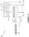
FIG. 4 is a schematic representation of another exemplary sampling tool; -
FIG. 5 is a schematic side elevation view of another exemplary tank of the lubrication system ofFIG. 2 with the sampling tool ofFIG. 4 detachably connected thereto; -
FIG. 6 shows an exemplary self-closing valve of the tank ofFIG. 5 with a cooperating connector of the sampling tool; -
FIG. 7A is a schematic side elevation view of the tank ofFIG. 5 with cover pieces in a covered position; -
FIG. 7B is a schematic side elevation view of the tank ofFIG. 5 with the cover pieces in an uncovered position; -
FIG. 7C is a schematic top view of the tank ofFIG. 5 with the cover pieces in the uncovered position; and -
FIG. 8 is a flow diagram of a method for collecting particles from lubrication fluid of an engine. - The sampling tool and method disclosed herein may be used to collect samples of particles filtered from lubrication fluid (lubricant) of gas turbine engines or other types of engines for the purpose of conducting analysis on such samples. Such analysis may be used to diagnose a condition of an engine. For example, the tool and method disclosed herein may be used in conjunction with lubrication fluid analysis methods such as those disclosed in
U.S. Patent No. 9,897,582 B2 U.S. Patent Publication No. 2017/0159485 A1 entitled METHOD AND SYSTEM FOR DIAGNOSING A CONDITION OF AN ENGINE USING LUBRICATION FLUID ANALYSIS. - Aspects of various embodiments are described through reference to the drawings.
-
FIG. 1 is a schematic axial cross-section view ofgas turbine engine 10 of a (e.g., turbo-fan) type preferably provided for use in subsonic flight, generally comprising in serialflow communication fan 12 through which ambient air is propelled,multistage compressor 14 for pressurizing the air,combustor 16 in which the compressed air is mixed with fuel and ignited for generating an annular stream of hot combustion gases, andturbine section 18 for extracting energy from the combustion gases.Engine 10 may be mounted to an aircraft and used to propel such aircraft.Engine 10 may includelubrication system 20 shown schematically inFIG. 1 .Lubrication system 20 may serve to lubricate, cool and clean one ormore lubrication loads 22 such as bearings and gears ofengine 10. -
FIG. 2 is an exemplary schematic representation oflubrication system 20 that may be part ofengine 10.Lubrication system 20 may includetank 24 and other components such as one ormore pumps more engine filters 28. Tank 24 may be a reservoir containing a supply oflubrication fluid 27 such as oil for use bylubrication system 20.Pump 26A may be a pressure pump for drivinglubrication fluid 27 toward lubrication load(s) 22.Pump 26B may be a scavenge pump for returninglubrication fluid 27 from sumps and bearing cavities back totank 24.Tank 24 may have one or moresystem supply ports 30A for supplyinglubrication fluid 27 to lubrication load(s) 22, and one or moresystem return ports 30B for returninglubrication fluid 27 from lubrication load(s) 22 back totank 24.Tank 24 may havefill port 31 for addinglubrication fluid 27 totank 24. Fillport 31 may be made accessible by the removal of a fill cap that is intended to be installed to andsecure fill port 31 during operation ofengine 10. -
Tank 24 may also havesampling port 32A and returnport 32B that may be used with a sampling tool as disclosed herein. In some embodiments,sampling port 32A and returnport 32B may be separate (i.e., different) from system supply and returnports tank 24. For example,sampling port 32A and returnport 32B may be dedicated for use with the sampling tool and otherwise not used during the operation ofengine 10. In other words, samplingport 32A and returnport 32B may not be used to supply lubrication load(s) 22 withlubrication fluid 27 during operation ofengine 10. Accordingly,sampling port 32A and returnport 32B may be covered by one ormore covers 34 so as to be secured and unavailable during operation ofengine 10. In some embodiments,sampling port 32A and returnport 32B may be separate (i.e., different) fromfill port 31 oftank 24. -
FIGS. 3A and 3B are schematic side elevation views oftank 24 oflubrication system 20.FIG. 3A showstank 24 in an in-use configuration during operation ofengine 10 wherelubrication fluid 27 may be supplied to lubrication load(s) 22 viasystem supply port 30A and returned back totank 24 viasystem return port 30B. In the in-use configuration, cover 34 is in the covered position wheresampling ports -
FIG. 3B showstank 24 in a sampling configuration whenengine 10 may be shut down. In the sampling configuration, cover 34 may be moved to an uncovered position wheresampling port 32A and returnport 32B may be uncovered and available for interfacing withsampling tool 36. In some embodiments, cover 34 may be movable (e.g., slidable) between the covered and the uncovered positions along arrow C. For example, cover 34 may be slidably engaged with a (e.g., top) wall oftank 24 via one or more suitable slides or tracks (not shown). In some embodiments, cover 34 may be resiliently biased toward the covered position (e.g., toward the right inFIG. 3B ), via one ormore springs 37 for example, so thatcover 34 may be manually pushed toward the uncovered position against the closing force exerted byspring 37 and held in the uncovered position to permit interfacing ofsampling tool 36 withtank 24. Oncesampling tool 36 is detachably connected totank 24 as shown inFIG. 3B , the presence ofsampling tool 36 may block the movement ofcover 34 toward the covered position and hence holdcover 34 in the uncovered position. -
Sampling tool 36 may be used to collect particles fromlubrication fluid 27 ofengine 10.Sampling tool 36 may be used whenengine 10 is shut down.Sampling tool 36 may be external to (i.e., not part of) lubrication system 20 (shown inFIG. 2 ) ofengine 10 but may be detachably connected to one or more components oflubrication system 20 during sampling. In some embodiments,sampling tool 36 may be a handheld and/or portable apparatus or unit that may be detachably connectable tolubrication system 20. Accordingly,sampling tool 36 may not be required for the normal operation oflubrication system 20 and ofengine 10. -
Sampling tool 36 may haveinlet 38 for receivinglubrication fluid 27 fromtank 24, filter-receivingportion 40 for receivingfilter 42, and pump 44 configured to induce a flow oflubrication fluid 27 throughfilter 42 disposed in filter-receivingportion 40. Filter-receivingportion 40 may be in fluid communication withinlet 38.Sampling tool 36 may includeoutlet 46 for returninglubrication fluid 27 totank 24 afterlubrication fluid 27 has passed throughfilter 42.Fluid passage 48 may establish fluid communication betweeninlet 38 andoutlet 46 ofsampling tool 36.Fluid passage 48 may define a flow loop that is external tolubrication system 20 ofengine 10 so thatfilter 42 is not disposed in-line within a flow circuit oflubrication system 20. -
Sampling tool 36 may includehousing 50 which may house pump 44 and optionally other components ofsampling tool 36. In some embodiments,housing 50 may include interfacingportion 52 for detachable connection withtank 24. In some embodiments, interfacingportion 52 may be configured to provide one or more sealed connections betweensampling tool 36 andtank 24. In some embodiments, a substantially liquid-sealed connection may be provided betweeninlet 38 andsampling port 32A via a suitable O-ring or other seal. The term "substantially" as used herein may be applied to modify any quantitative representation which could permissibly vary without resulting in a change in the basic function to which it is related. -
Pump 44 may be disposed downstream ofinlet 38.Pump 44 may be disposed downstream of filter-receivingportion 40.Pump 44 may be of a type suitable to generate a partial vacuum condition upstream thereof in order to drawlubrication fluid 27 fromtank 24 intoinlet 38 ofsampling tool 36. In some embodiments, pump 44 may be a velocity pump such as a radial-flow pump or an axial-flow pump for example.Pump 44 may be configured to drivelubrication fluid 27 towardoutlet 46.Pump 44 may be operatively disposed alongfluid passage 48 betweeninlet 38 andoutlet 46.Pump 44 may be electrically powered and may be driven using a power source that is external toengine 10. Alternatively, pump 44 may be manually powered and driven by an operator ofsampling tool 36. - In some embodiments,
tank 24 may includetube 54 through whichlubrication fluid 27 is drawn (see arrow "S") and delivered toinlet 38 via samplingport 32A.Tube 54 may extend into the interior oftank 24 so thatlubrication fluid 27 may be drawn at a desired height H from a bottom oftank 24 to avoid collecting particles that have settled to the bottom oftank 24 for example. Height H may also be selected to be at some depth below the surface oflubrication fluid 27 in order to collect particles that remain suspended inlubrication fluid 27 for some time after shutting downengine 10. Height H may be selected based on the type ofengine 10 and also based on the type (e.g., size, composition, morphology and/or density) of particles that are of interest for the lubrication fluid analysis. In some embodiments,tube 54 may be permanently installed intank 24 and may be part oftank 24. Alternatively,tube 54 may be part ofsampling tool 36 and may extend intotank 24 throughsampling port 32A. - Filter-receiving
portion 40 may be a receptacle for holding one ormore filters 42 in series withfluid passage 48.Filter 42 may include a screen, mesh or fabric (cloth) or a combination thereof. In some embodiments, filter 42 may be configured to capture relatively fine particles that would not be captured by engine filter 28 (shown inFIG. 2 ). In some embodiments, filter 42 may be a very fine filter, such as a 0.22 µm filter that is able to filter out even very small particles (e.g., as small as 0.5 µm in diameter or smaller). In some embodiments, filter 42 may be configured to collect particles that range in size from about 0.5 µm to about 1600 µm, for example. The type offilter 42 may be selected based on the type of particles that are of interest. In some embodiments, filter 42 may be a membrane filter. For example, filter 42 may be a membrane filter disposed inside a suitable holder (e.g., cartridge) for installation in filter-receivingportion 40. - In some embodiments,
sampling tool 36 may haveflowmeter 55 that is configured to measure the flow oflubrication fluid 27 induced bypump 44. In some embodiments,flowmeter 55 may be configured to measure a current flowrate oflubrication fluid 27 throughfluid passage 48. In some embodiments,flowmeter 55 may be configured to measure and indicate a cumulative volume oflubrication fluid 27 being induced bypump 44.Flowmeter 55 may provide a useful indication that allows an operator ofsampling tool 36 to control the operation ofpump 44 in order to cause only a prescribed amount (e.g., volume) of lubrication fluid to pass throughfilter 42 for controlled and repeatable sample collection. In some embodiments, the timely deactivation ofpump 44 may be achieved manually by an operator based on an indication fromflowmeter 55. In some embodiments, the timely deactivation ofpump 44 may be achieved automatically by way of a trigger signal generated byflowmeter 55 once the prescribed amount oflubrication fluid 27 has passed throughfilter 42. - In some embodiments,
sampling tool 36 may be devoid of any reservoir for collecting a sample oflubrication fluid 27. Accordingly, most or substantially all oflubrication fluid 27 that is drawn intoinlet 38 may be returned totank 24 viaoutlet 46.Filter 42 with the particles captured therein may be sent to a suitable testing facility to perform the desired analysis and diagnose a condition ofengine 10. Accordingly, returninglubrication fluid 27 back totank 24 through the use ofsampling tool 36 may significantly reduce wastage oflubrication fluid 27 especially when samples are collected at regular intervals onseveral engines 10. Returninglubrication fluid 27 back totank 24 may also reduced shipping costs by reducing the size and weight of the samples that are shipped to the testing facility. - In some embodiments,
tank 24 may include one or more optional self-closing valves 59 (described in more detail below in reference toFIG. 6 ) associated with samplingport 32A and/or returnport 32B. Self-closingvalves 59 may be configurable between a closed configuration where a flow oflubrication fluid 27 throughsampling port 32A and/or returnport 32B is prevented and an open configuration where the flow oflubrication fluid 27 throughsampling port 32A and/or returnport 32B is permitted. During use ofsampling tool 36,inlet 38 or other part(s) ofsampling tool 36 may be releasably engaged with self-closingvalve 59 associated with samplingport 32A to cause opening of self-closingvalve 59. Similarly, during use ofsampling tool 36,outlet 46 or other part(s) ofsampling tool 36 may be releasably engaged with self-closingvalve 59 associated withreturn port 32B to cause opening of self-closingvalve 59. Self-closing valve(s) 59 may be configured to be in the open configuration when samplingtool 36 is being used, and automatically return to the closed configuration when samplingtool 36 is disconnected fromtank 24 and not being used. - The use of
dedicated sampling port 32A and returnport 32B with associated optional self-closingvalves 59 may reduce safety risks associated with the use ofsampling tool 36. For example, since sampling and returnports fill port 31, the removal of a fill cap associated withfill port 31 may not be required to usesampling tool 36. Accordingly, the risk of leakage or contamination oflubrication fluid 27 due to fill cap being inadvertently left uninstalled after the use ofsampling tool 36 and during operation ofengine 10 may be reduced. Also, the use of self-closingvalves 59 may automatically cause closing of sampling and returnports tool 36 is disconnected fromtank 24 so that the risk of leakage or contamination oflubrication fluid 27 due tosuch ports engine 10 is also reduced or eliminated. -
FIG. 4 is a schematic representation of anotherexemplary sampling tool 360.Tool 360 may have components in common withtool 36 described above and like elements have been identified using like reference numerals.FIG. 4 shows filter 42 removed fromtool 360 and indicates an insertion direction (see arrow F) for insertingfilter 42 intotool 360. As explained below, filter 42 may be disposed inside a suitable cartridge that is permeable tolubrication fluid 27 and that allowsfilter 42 to be removably retained in filter-receivingportion 40 oftool 360.Tool 360 may include an optional piece ofporous glass 56 disposed downstream offilter 42 and through whichlubrication fluid 27 is also induced to pass.Porous glass 56 may be a glass filter disc. - In some embodiments,
housing 50 oftool 360 may house pump 44,flowmeter 55 filter-receivingportion 40.Interfacing portion 52 ofhousing 50 may be detachably connectable withlubrication system 20. In some embodiments, interfacingportion 52 ofhousing 50 may includeseal 58 which may be an O-ring or other type of seal to provide a fluid-sealed interface betweentool 360 andlubrication system 20 ofengine 10. -
FIG. 5 is a schematic side elevation view of anotherexemplary tank 240 oflubrication system 20 ofengine 10 withsampling tool 360 detachably connected thereto.Tank 240 may includereceptacle 60 formed in a upper wall oftank 240 for example.Receptacle 60 may have a shape that is complementary to the shape of interfacingportion 52 ofhousing 50 so that interfacingportion 52 ofhousing 50 may be received inreceptacle 60 whentool 360 is detachably connected totank 240.Seal 58 may be disposed between interfacingportion 52 ofhousing 50 and one or more walls ofreceptacle 60.Seal 58 may provide a sealed interface betweenhousing 50 andtank 240. It is understood that a separate substantially sealed interface may be provided betweeninlet 38 oftool 360 andsampling port 32A. -
Tank 240 may include a two-piece cover 34 (e.g.,pieces receptacle 60 andsampling ports engine 10.Cover pieces receptacle 60 andsampling ports cover pieces cover 34 of tank 24 (seeFIG. 3B ) or in a different manner. -
FIG. 6 shows an exemplary self-closingvalve 59 oftank 24 with a cooperatingconnector 62 ofsampling tool 36. One ormore connectors 62 may be connected to part ofsampling tool 36 via threadedinterface 64. For example, oneconnector 62 may defineinlet 38 and anotherconnector 62 may define outlet 46 (seeFIG. 3B ).Connector 62 may have a through central passage for the flow oflubrication fluid 27 and in fluid communication withfluid passage 48 ofsampling tool 36.Connector 62 may be configured to engage with self-closingvalve 59 when samplingtool 36 is in use and can cause self-closingvalve 59 to adopt the open configuration. - Self-closing
valve 59 is shown in a partially sectioned and perspective view to illustrate internal components thereof. One or more self-closingvalves 59 may be connected to part oftank 24 via threadedinterface 66. For example, one self-closingvalve 59 may definesampling port 32A and another self-closingvalve 59 may definereturn port 32B (e.g., seeFIG. 3B ). Self-closingvalve 59 may have a through central passage for the flow oflubrication fluid 27. Self-closingvalve 59 may havevalve member 68 movably disposed insidehousing 70.Valve member 68 may be resiliently biased byspring 72 toward a valve-closed position that is shown inFIG. 6 . In the valve-closed position, a sealing surface 76 (shoulder) may be in sealing contact withseal 78 in order to substantially prevent the flow oflubrication fluid 27 out of samplingport 32A and/or out ofreturn port 32B. - When sampling
tool 36 is brought in releasable engagement withtank 24 for the purpose of obtaining a sample of particles fromlubrication fluid 27,connector 62 may be inserted into self-closingvalve 59 and may pushvalve member 68 and cause movement ofvalve member 68 to a valve-open position whereannular sealing surface 76 andannular seal 78 are no longer in contact and no longer provide sealing. The pushing ofvalve member 68 byconnector 62 would overcome the closing force provided byspring 72. When samplingtool 36 is removed fromtank 24 after a sampling procedure, the withdrawal ofconnector 62 from self-sealingvalve 59 may allowvalve member 68 to automatically return to its valve-closed position due to the closing force provided byspring 72. - The combination of
connector 62 and self-sealingvalve 59 may define a quick connect/release fitting betweensampling tool 36 andtank 24. In some embodiments, self-sealingvalve 59 may be a check valve that prevents fluid flow out oftank 24 except when self-sealingvalve 59 is urged to a valve-open configuration byconnector 62 for example. It is understood that self-closingvalve 59 could be of other type than illustrated herein. For example, self-closingvalve 59 could be a ball check valve, a diaphragm check valve, a swing check valve, a flapper valve or a lift check valve in various embodiments. -
FIG. 7A is a schematic side elevation view oftank 240 withcover pieces -
FIG. 7B is a schematic side elevation view oftank 240 withcover pieces -
FIG. 7C is a schematic top view oftank 240 withcover pieces receptacle 60 and interfacingportion 52 ofhousing 50 may each have a circular cross-section profile but it is understood that other shapes of cross-sectional profiles may also be suitable. -
FIG. 8 is a flow diagram ofmethod 100 for collecting particles fromlubrication fluid 27 ofengine 10.Method 100 may be performed usingsampling tools tools method 100.Method 100 may include: - when
engine 10 is shut down, inducing a flow oflubrication fluid 27 fromtank engine 10 throughfilter 42 to collect particles from lubrication fluid 27 (see block 102); and - returning
lubrication fluid 27 that has passed throughfilter 42 back totank 24, 240 (see block 104). -
Method 100 may include inducing only a prescribed amount oflubrication fluid 27 throughfilter 42.Method 100 may include usingpump 44 external tolubrication system 20 ofengine 10 to induce the flow oflubrication fluid 27 fromtank Filter 42 may be external tolubrication system 20 ofengine 10. - The timing of the acquisition of the particles after shut down of
engine 10 may also be prescribed based on particles of interest that are expected to still be suspended inlubrication fluid 27. For example,method 100 may be performed within a prescribed time window from the shut down ofengine 10 in order to provide consistent and repeatable analysis. - The above description is meant to be exemplary only, and one skilled in the relevant arts will recognize that changes may be made to the embodiments described without departing from the scope of the invention disclosed. The present disclosure may be embodied in other specific forms without departing from the subject matter of the claims. The present disclosure is intended to cover and embrace all suitable changes in technology. Modifications which fall within the scope of the present invention will be apparent to those skilled in the art, in light of a review of this disclosure, and such modifications are intended to fall within the appended claims. Also, the scope of the claims should not be limited by the preferred embodiments set forth in the examples, but should be given the broadest interpretation consistent with the description as a whole.
Claims (15)
- An oil sampling assembly for an aircraft engine (10), the oil sampling assembly comprising:a tank (24;240) of the aircraft engine (10), the tank (24;240) containing lubrication fluid (27) of the engine (10), the tank (24;240) including a port (32A) and a self-closing valve (59) configurable between a closed configuration where a flow of lubrication fluid (27) through the port (32A) is prevented and an open configuration where the flow of lubrication fluid (27) through the port (32A) is permitted; andan oil sampling tool (36;360) releasably engaged with the self-closing valve (59) to cause opening of the self-closing valve (59), the sampling tool (36;360) having:an inlet (38) in fluid communication with the port (32A) for receiving the flow of lubrication fluid (27) from the tank (24;240) via the port (32A);a filter (42) in fluid communication with the inlet (38); anda pump (44) configured to induce the flow of the lubrication fluid (27) through the filter (42).
- The oil sampling assembly as defined in claim 1, wherein:the port (32A) is a sampling port (32A);the tank (24;240) has a return port (32B); andthe oil sampling tool (36;360) has an outlet (46) in fluid communication with the return port (32B) for returning the lubrication fluid (27) to the tank (24:240).
- The oil sampling assembly as defined in claim 2, wherein:the self-closing valve (59) is a first self-closing valve (59); andthe tank (24;240) includes a second self-closing valve (59) associated with the return port (32B).
- The oil sampling assembly as defined in claim 2 or 3, wherein the pump (44) is operatively disposed between the inlet (38) and the outlet (46), and/or is disposed downstream of the filter (42).
- The oil sampling assembly as defined in any preceding claim, wherein the oil sampling tool (36;360) includes a flowmeter (55) configured to measure the flow of lubrication fluid (27) induced by the pump (44).
- The oil sampling assembly as defined in any preceding claim, wherein:the oil sampling tool (36;360) includes a connector (62) defining the inlet (38); andthe connector (62) is configured to engage with the self-closing valve (59) to cause opening of the self-closing valve (59).
- The oil sampling assembly as defined in any preceding claim, wherein the port (32A) is a/the sampling port (32A) that is different from a fill port (31) of the tank (24;240) and also different from a supply port (30A) for supplying the lubrication fluid (27) to a lubrication load (22) of the engine (10).
- The oil sampling assembly as defined in any preceding claim, wherein the oil sampling tool (36;360) is devoid of a reservoir for collecting a sample of the lubrication fluid (27).
- An assembly comprising:an engine (10) having a tank (24;240) containing lubrication fluid (27) of the engine (10), the tank (24;240) including a supply port (30A) for supplying the lubrication fluid (27) to a lubrication load (22) of the engine (10), and a sampling port (32A); anda sampling tool (36;360) configured to collect particles from the lubrication fluid (27) contained in the tank (24;240), the sampling tool (36;360) including:an inlet (38) in fluid communication with the sampling port (32A) for receiving the lubrication fluid (27) from the tank (24;240);a filter (42) in fluid communication with the inlet (38); anda pump (44) configured to induce a flow of the lubrication fluid (27) through the filter (42).
- The assembly as defined in claim 9, wherein:the tank (24;240) has a return port (32B);the sampling tool (36;360) has an outlet (46) in fluid communication with the return port (32B) for returning the lubrication fluid (27) to the tank (24;240); and/orthe sampling port (32A) is different from a fill port (31) of the tank (24;240).
- The assembly as defined in claim 9 or 10, comprising a cover (34) for covering the sampling port (32A) during operation of the engine (10), wherein, optionally:the cover (34) is movable between a covered position where the sampling port (32A) is covered by the cover (34), and an uncovered position where the sampling port (32A) is uncovered; andthe cover (34) is resiliently biased toward the covered position.
- The assembly as defined in claim 9, 10 or 11, comprising a housing (50) wherein:the pump (44) is housed by the housing (50); anda portion (52) of the housing (50) is received in a receptacle (60) formed in the tank (24;240), wherein, optionally, the assembly further comprises a seal (58) disposed between the receptacle (60) formed in the tank (24;240) and the portion (52) of the housing (50) received in the receptacle (60).
- A method for collecting particles from lubrication fluid (27) of an engine (10), the method comprising:when the engine (10) is shut down, inducing a flow of lubrication fluid (27) from a tank (24;240) of the engine (10) through a filter (42) to collect particles from the lubrication fluid (27); andreturning the lubrication fluid (27) that has passed through the filter (42) back to the tank (24;240).
- The method as defined in claim 13, comprising inducing only a prescribed amount of the lubrication fluid (27) through the filter (42).
- The method as defined in claim 13 or 14, comprising using a pump (44) external to a lubrication system (20) of the engine (10) to induce the flow of lubrication fluid (27) from the tank (24;240); and/or the filter (42) being external to the lubrication system (20) of the engine (10).
Applications Claiming Priority (1)
| Application Number | Priority Date | Filing Date | Title |
|---|---|---|---|
| US16/546,654 US11454571B2 (en) | 2019-08-21 | 2019-08-21 | Sampling tool for lubricating fluid analysis |
Publications (2)
| Publication Number | Publication Date |
|---|---|
| EP3783361A1 true EP3783361A1 (en) | 2021-02-24 |
| EP3783361B1 EP3783361B1 (en) | 2023-09-27 |
Family
ID=72178417
Family Applications (1)
| Application Number | Title | Priority Date | Filing Date |
|---|---|---|---|
| EP20191917.2A Active EP3783361B1 (en) | 2019-08-21 | 2020-08-20 | Sampling tool for lubricating fluid analysis |
Country Status (2)
| Country | Link |
|---|---|
| US (1) | US11454571B2 (en) |
| EP (1) | EP3783361B1 (en) |
Families Citing this family (1)
| Publication number | Priority date | Publication date | Assignee | Title |
|---|---|---|---|---|
| US11383854B2 (en) * | 2019-12-30 | 2022-07-12 | Hamilton Sundstrand Corporation | Oil reservoir vent valve |
Citations (7)
| Publication number | Priority date | Publication date | Assignee | Title |
|---|---|---|---|---|
| WO2002087726A1 (en) * | 2001-04-26 | 2002-11-07 | Engineered Machined Products, Inc. | Auxiliary filtration system and filtering method |
| US20070180934A1 (en) * | 2006-02-03 | 2007-08-09 | Morris James O | Liquid sampling apparatus |
| US20120080384A1 (en) * | 2010-09-30 | 2012-04-05 | Adan Reinosa | Method and apparatus for a parallel bypass filtration system for internal combustion engines and similar systems |
| US20150308304A1 (en) * | 2012-06-08 | 2015-10-29 | RPM Industries, LLC | Variable fluid flow techniques for machine fluid systems |
| US20170159485A1 (en) | 2015-12-08 | 2017-06-08 | Pratt & Whitney Canada Corp. | Method and system for diagnosing a condition of an engine using lubricating fluid analysis |
| US9897582B2 (en) | 2012-10-26 | 2018-02-20 | Pratt & Whitney Canada Corp. | Method and system for failure prediction using lubricating fluid analysis |
| US20190234860A1 (en) * | 2018-01-31 | 2019-08-01 | Pratt & Whitney Canada Corp. | Method and system for predicting engine performance |
Family Cites Families (53)
| Publication number | Priority date | Publication date | Assignee | Title |
|---|---|---|---|---|
| US1753394A (en) * | 1928-05-31 | 1930-04-08 | Orville C Watson | Thief-hole cover |
| US2447595A (en) * | 1945-04-16 | 1948-08-24 | Gulf Research Development Co | Sampler for gas-liquid mixtures |
| US3068442A (en) * | 1961-01-16 | 1962-12-11 | John T Kubik | Safety guard for wall sockets |
| US3242739A (en) * | 1963-01-09 | 1966-03-29 | Joseph L Botkin | Sampling valve |
| US3400575A (en) * | 1966-01-28 | 1968-09-10 | Cox Instr | Contaminant sampling apparatus and method |
| US3681562A (en) * | 1970-01-12 | 1972-08-01 | John P Winzen | Filter device and transparent cover |
| AU498574B2 (en) * | 1974-06-13 | 1979-03-15 | Mobil Oil Australia Limited | Determining wear |
| US4612815A (en) * | 1985-02-14 | 1986-09-23 | Green Dennis A | Method and apparatus for sampling hazardous material |
| US4640466A (en) * | 1985-04-01 | 1987-02-03 | Semyon Fishgal | Contaminants breaking and separation |
| US4640564A (en) * | 1986-03-04 | 1987-02-03 | Hill Joe W | Electrical outlet faceplate with locking closures |
| US4944178A (en) * | 1988-04-18 | 1990-07-31 | Nissin Electric Co., Ltd | Apparatus and method for measuring dissolved gas in oil |
| US4930360A (en) * | 1989-07-21 | 1990-06-05 | Balazs Analytical Laboratory | Liquids sampler |
| US5237878A (en) * | 1991-07-02 | 1993-08-24 | Sematech, Inc. | Apparatus and method for sampling ultra-pure chemical |
| US5262732A (en) * | 1991-12-11 | 1993-11-16 | Computational Systems, Inc. | Oil monitor with magnetic field |
| ES2132260T3 (en) * | 1992-10-13 | 1999-08-16 | Baxter Int | FLUID SAMPLING MODULE. |
| US5289900A (en) * | 1992-12-28 | 1994-03-01 | United Technologies Corporation | Multi-functional service for lubrication tank |
| GB9309205D0 (en) * | 1993-05-04 | 1993-06-16 | Solinst Canada Ltd | Groundwater sampler |
| US5437199A (en) * | 1994-02-16 | 1995-08-01 | Kaplan; Larry | Sampling kit for compressed air/gas sources |
| US5788858A (en) * | 1996-05-03 | 1998-08-04 | Terra Group, Inc. | Mobile water purification unit with modular dechlorination input stage |
| US6095572A (en) * | 1998-01-20 | 2000-08-01 | Optimize Technologies, Inc. | Quarter turn quick connect fitting |
| US6223590B1 (en) * | 1998-01-30 | 2001-05-01 | Janos Technology Inc. | Volatilization device for liquids |
| US6065488A (en) * | 1998-12-11 | 2000-05-23 | The Regents Of The University Of California | Fluid sampling tool |
| US6568342B2 (en) * | 2000-02-10 | 2003-05-27 | Boston Whaler, Inc. | Sliding deck assembly providing engine compartment access |
| US6391096B1 (en) * | 2000-06-09 | 2002-05-21 | Serveron Corporation | Apparatus and method for extracting and analyzing gas |
| US6643570B2 (en) * | 2000-06-22 | 2003-11-04 | Barry Bangert | Aircraft engine reliability business model |
| US6568287B2 (en) * | 2000-12-29 | 2003-05-27 | Waukesha Electric Systems | Oil sampling system and method for electrical power devices |
| US6513367B2 (en) * | 2001-02-22 | 2003-02-04 | International Truck Intellectual Property Company, L.L.C. | Method of monitoring engine lubricant condition |
| US9976770B2 (en) * | 2005-03-21 | 2018-05-22 | Camfil Usa, Inc. | Exhaust filter module, and a method and apparatus for efficiency testing the same |
| US20070029007A1 (en) * | 2005-07-25 | 2007-02-08 | Hutchinson Douglas C | Machine and process for sampling, venting or viewing suspected HAZMAT drums, containers, ductwork or various enclosures without leakage |
| US7757815B2 (en) | 2005-11-18 | 2010-07-20 | General Electric Company | Method and apparatus for sampling lubricant |
| US7938029B2 (en) | 2006-10-31 | 2011-05-10 | Campbell D Michael | Simplified oil sampling assembly |
| WO2009021112A2 (en) * | 2007-08-07 | 2009-02-12 | Miguel Linares | Plasticized and assembleable cover such as for use with waterway constructed transport barges |
| US9010814B2 (en) * | 2008-04-15 | 2015-04-21 | Marshall Excelsior Co. | Quick fill fluid connector |
| EP2389532B1 (en) * | 2009-01-21 | 2019-02-27 | TF Hudgins Inc. | High pressure lubricating system |
| WO2011014119A1 (en) * | 2009-07-27 | 2011-02-03 | The Thailand Research Fund | An apparatus and method for particle analysis |
| US8572974B2 (en) * | 2009-07-31 | 2013-11-05 | Hamilton Sundstrand Corporation | Variable speed and displacement electric fluid delivery system for a gas turbine engine |
| JP4924707B2 (en) * | 2009-12-25 | 2012-04-25 | 株式会社日立プラントテクノロジー | Detected object collector and method of using the same |
| US9696243B2 (en) | 2010-01-12 | 2017-07-04 | Jose Lopez | Fluid sampling system |
| US20110174250A1 (en) * | 2010-01-20 | 2011-07-21 | Mr. Richard Andrew Borde | Auxiliary electric oil booster pump apparatus for a motorcycle |
| US8442775B2 (en) * | 2010-04-02 | 2013-05-14 | Eduardo Pedrosa Santos | System and method for monitoring dissolved gases in insulating oil of high voltage equipment |
| US9194502B2 (en) * | 2010-05-24 | 2015-11-24 | Emerson Process Management Regulator Technologies, Inc. | Methods and apparatus for removing fluid from fluid valves |
| US8578796B2 (en) * | 2010-06-11 | 2013-11-12 | U.S. Departement of Homeland Security | High volume sampling front end collection device |
| GB2487436B (en) * | 2011-01-24 | 2013-10-09 | Framo Eng As | Conduit for a hydrocarbon transport pipeline,related method and system |
| US20120210769A1 (en) * | 2011-02-23 | 2012-08-23 | Aerosoft, Llc | Apparatus and methods for fluid contamination detection system |
| US20130197830A1 (en) * | 2012-02-01 | 2013-08-01 | Afton Chemical Corporation | System and method for determining a lubricant discard interval |
| US10031090B2 (en) * | 2015-06-16 | 2018-07-24 | Atomic Energy Of Canada Limited | Portable detection apparatus and method |
| US10330664B2 (en) * | 2015-06-18 | 2019-06-25 | Pratt & Whitney Canada Corp. | Evaluation of component condition through analysis of material interaction |
| US20170336380A1 (en) * | 2016-05-23 | 2017-11-23 | John C. Kupferle Foundry Company | Portable flushing monitor |
| DE102016007668A1 (en) * | 2016-06-24 | 2017-12-28 | Testo SE & Co. KGaA | Oil meter and method for monitoring an oil in a tank |
| US10881887B2 (en) * | 2017-09-14 | 2021-01-05 | Agf Manufacturing, Inc. | Valve system and method for venting and measuring a gas content of a fire suppression system |
| US12226586B2 (en) * | 2017-11-02 | 2025-02-18 | C. R. Bard, Inc. | Drainage system and method |
| US10732190B2 (en) * | 2018-01-31 | 2020-08-04 | Pratt & Whitney Canada Corp. | Method and system for predicting an engine condition |
| US11066285B2 (en) * | 2019-01-22 | 2021-07-20 | Vijay Singh | Dispensing apparatus for aging and storing wine in flexible containers |
-
2019
- 2019-08-21 US US16/546,654 patent/US11454571B2/en active Active
-
2020
- 2020-08-20 EP EP20191917.2A patent/EP3783361B1/en active Active
Patent Citations (7)
| Publication number | Priority date | Publication date | Assignee | Title |
|---|---|---|---|---|
| WO2002087726A1 (en) * | 2001-04-26 | 2002-11-07 | Engineered Machined Products, Inc. | Auxiliary filtration system and filtering method |
| US20070180934A1 (en) * | 2006-02-03 | 2007-08-09 | Morris James O | Liquid sampling apparatus |
| US20120080384A1 (en) * | 2010-09-30 | 2012-04-05 | Adan Reinosa | Method and apparatus for a parallel bypass filtration system for internal combustion engines and similar systems |
| US20150308304A1 (en) * | 2012-06-08 | 2015-10-29 | RPM Industries, LLC | Variable fluid flow techniques for machine fluid systems |
| US9897582B2 (en) | 2012-10-26 | 2018-02-20 | Pratt & Whitney Canada Corp. | Method and system for failure prediction using lubricating fluid analysis |
| US20170159485A1 (en) | 2015-12-08 | 2017-06-08 | Pratt & Whitney Canada Corp. | Method and system for diagnosing a condition of an engine using lubricating fluid analysis |
| US20190234860A1 (en) * | 2018-01-31 | 2019-08-01 | Pratt & Whitney Canada Corp. | Method and system for predicting engine performance |
Non-Patent Citations (1)
| Title |
|---|
| ANONYMOUS: "Filtration Approved by the US Patent Office -A major innovation in bypass filtration and the first to deploy parallel-flow technology", 12 November 2014 (2014-11-12), San Pedro, CA, US, pages 1 - 2, XP055760730, Retrieved from the Internet <URL:https://paretopoint.com/blogs/news/pareto-point-industries-patent-application-for-parallel-flow-oil-bypass-filtration-approved-by-the-us-patent-office-a-major-innovation-in-bypass-filtration-and-the-first-to-deploy-parallel-flow-technology> [retrieved on 20201216] * |
Also Published As
| Publication number | Publication date |
|---|---|
| US11454571B2 (en) | 2022-09-27 |
| EP3783361B1 (en) | 2023-09-27 |
| US20210055185A1 (en) | 2021-02-25 |
Similar Documents
| Publication | Publication Date | Title |
|---|---|---|
| US11118996B2 (en) | Oil filter-leak pressure-test station | |
| EP0548187B1 (en) | A method and a sampling assembly for taking a representative fluid sample from a pressurized fluid system | |
| WO2009108443A1 (en) | Method and system for fluid sampling | |
| EP3783361B1 (en) | Sampling tool for lubricating fluid analysis | |
| CN110230768A (en) | New forms of energy electric automobile's driving motor lubricating system | |
| US10259597B1 (en) | Aircraft fuel system test unit | |
| CN207992213U (en) | Lubricating oil high temperature deposition characteristics detection test device and detection test system | |
| US9175805B2 (en) | Lubricant filtration system | |
| US11698025B2 (en) | Oil leakage monitoring system | |
| US7938029B2 (en) | Simplified oil sampling assembly | |
| US3771624A (en) | Contaminant collection means for recirculating fluid system | |
| CN102165175A (en) | Filter assembly | |
| CA2964089C (en) | Oil leakage recovery system for gas turbine engine | |
| US6709478B2 (en) | Engine crank case sampling system | |
| CN212867540U (en) | Airtight sampling device is used to oil gas field ground engineering | |
| US3974659A (en) | Oil sampling and charging method and apparatus for refrigeration systems | |
| US20140041388A1 (en) | Aircraft Fuel System Test Unit | |
| AU2011258681A1 (en) | Methods and apparatus for removing fluid from valves | |
| US20140202554A1 (en) | Enhanced techniques for performing and monitoring machine fluid processes | |
| CN215677701U (en) | Sampling testing device and aviation fuel supply system | |
| JP2584591B2 (en) | Lubricating oil sampler | |
| CN221107485U (en) | Waste gas filtering equipment | |
| CN223565239U (en) | Online inspection tool for breather valve of storage tank | |
| CN201434197Y (en) | Multi-Purpose Recovery Fuel Tank | |
| RU210245U1 (en) | Stand for testing aircraft engines and their components |
Legal Events
| Date | Code | Title | Description |
|---|---|---|---|
| PUAI | Public reference made under article 153(3) epc to a published international application that has entered the european phase |
Free format text: ORIGINAL CODE: 0009012 |
|
| STAA | Information on the status of an ep patent application or granted ep patent |
Free format text: STATUS: THE APPLICATION HAS BEEN PUBLISHED |
|
| AK | Designated contracting states |
Kind code of ref document: A1 Designated state(s): AL AT BE BG CH CY CZ DE DK EE ES FI FR GB GR HR HU IE IS IT LI LT LU LV MC MK MT NL NO PL PT RO RS SE SI SK SM TR |
|
| AX | Request for extension of the european patent |
Extension state: BA ME |
|
| STAA | Information on the status of an ep patent application or granted ep patent |
Free format text: STATUS: REQUEST FOR EXAMINATION WAS MADE |
|
| 17P | Request for examination filed |
Effective date: 20210824 |
|
| RBV | Designated contracting states (corrected) |
Designated state(s): AL AT BE BG CH CY CZ DE DK EE ES FI FR GB GR HR HU IE IS IT LI LT LU LV MC MK MT NL NO PL PT RO RS SE SI SK SM TR |
|
| GRAP | Despatch of communication of intention to grant a patent |
Free format text: ORIGINAL CODE: EPIDOSNIGR1 |
|
| STAA | Information on the status of an ep patent application or granted ep patent |
Free format text: STATUS: GRANT OF PATENT IS INTENDED |
|
| INTG | Intention to grant announced |
Effective date: 20230301 |
|
| GRAS | Grant fee paid |
Free format text: ORIGINAL CODE: EPIDOSNIGR3 |
|
| GRAA | (expected) grant |
Free format text: ORIGINAL CODE: 0009210 |
|
| STAA | Information on the status of an ep patent application or granted ep patent |
Free format text: STATUS: THE PATENT HAS BEEN GRANTED |
|
| AK | Designated contracting states |
Kind code of ref document: B1 Designated state(s): AL AT BE BG CH CY CZ DE DK EE ES FI FR GB GR HR HU IE IS IT LI LT LU LV MC MK MT NL NO PL PT RO RS SE SI SK SM TR |
|
| REG | Reference to a national code |
Ref country code: GB Ref legal event code: FG4D |
|
| REG | Reference to a national code |
Ref country code: CH Ref legal event code: EP |
|
| REG | Reference to a national code |
Ref country code: DE Ref legal event code: R096 Ref document number: 602020018186 Country of ref document: DE |
|
| REG | Reference to a national code |
Ref country code: IE Ref legal event code: FG4D |
|
| REG | Reference to a national code |
Ref country code: LT Ref legal event code: MG9D |
|
| PG25 | Lapsed in a contracting state [announced via postgrant information from national office to epo] |
Ref country code: GR Free format text: LAPSE BECAUSE OF FAILURE TO SUBMIT A TRANSLATION OF THE DESCRIPTION OR TO PAY THE FEE WITHIN THE PRESCRIBED TIME-LIMIT Effective date: 20231228 |
|
| PG25 | Lapsed in a contracting state [announced via postgrant information from national office to epo] |
Ref country code: SE Free format text: LAPSE BECAUSE OF FAILURE TO SUBMIT A TRANSLATION OF THE DESCRIPTION OR TO PAY THE FEE WITHIN THE PRESCRIBED TIME-LIMIT Effective date: 20230927 Ref country code: RS Free format text: LAPSE BECAUSE OF FAILURE TO SUBMIT A TRANSLATION OF THE DESCRIPTION OR TO PAY THE FEE WITHIN THE PRESCRIBED TIME-LIMIT Effective date: 20230927 Ref country code: NO Free format text: LAPSE BECAUSE OF FAILURE TO SUBMIT A TRANSLATION OF THE DESCRIPTION OR TO PAY THE FEE WITHIN THE PRESCRIBED TIME-LIMIT Effective date: 20231227 Ref country code: LV Free format text: LAPSE BECAUSE OF FAILURE TO SUBMIT A TRANSLATION OF THE DESCRIPTION OR TO PAY THE FEE WITHIN THE PRESCRIBED TIME-LIMIT Effective date: 20230927 Ref country code: LT Free format text: LAPSE BECAUSE OF FAILURE TO SUBMIT A TRANSLATION OF THE DESCRIPTION OR TO PAY THE FEE WITHIN THE PRESCRIBED TIME-LIMIT Effective date: 20230927 Ref country code: HR Free format text: LAPSE BECAUSE OF FAILURE TO SUBMIT A TRANSLATION OF THE DESCRIPTION OR TO PAY THE FEE WITHIN THE PRESCRIBED TIME-LIMIT Effective date: 20230927 Ref country code: GR Free format text: LAPSE BECAUSE OF FAILURE TO SUBMIT A TRANSLATION OF THE DESCRIPTION OR TO PAY THE FEE WITHIN THE PRESCRIBED TIME-LIMIT Effective date: 20231228 Ref country code: FI Free format text: LAPSE BECAUSE OF FAILURE TO SUBMIT A TRANSLATION OF THE DESCRIPTION OR TO PAY THE FEE WITHIN THE PRESCRIBED TIME-LIMIT Effective date: 20230927 |
|
| REG | Reference to a national code |
Ref country code: NL Ref legal event code: MP Effective date: 20230927 |
|
| REG | Reference to a national code |
Ref country code: AT Ref legal event code: MK05 Ref document number: 1615889 Country of ref document: AT Kind code of ref document: T Effective date: 20230927 |
|
| PG25 | Lapsed in a contracting state [announced via postgrant information from national office to epo] |
Ref country code: NL Free format text: LAPSE BECAUSE OF FAILURE TO SUBMIT A TRANSLATION OF THE DESCRIPTION OR TO PAY THE FEE WITHIN THE PRESCRIBED TIME-LIMIT Effective date: 20230927 |
|
| PG25 | Lapsed in a contracting state [announced via postgrant information from national office to epo] |
Ref country code: IS Free format text: LAPSE BECAUSE OF FAILURE TO SUBMIT A TRANSLATION OF THE DESCRIPTION OR TO PAY THE FEE WITHIN THE PRESCRIBED TIME-LIMIT Effective date: 20240127 |
|
| PG25 | Lapsed in a contracting state [announced via postgrant information from national office to epo] |
Ref country code: AT Free format text: LAPSE BECAUSE OF FAILURE TO SUBMIT A TRANSLATION OF THE DESCRIPTION OR TO PAY THE FEE WITHIN THE PRESCRIBED TIME-LIMIT Effective date: 20230927 |
|
| PG25 | Lapsed in a contracting state [announced via postgrant information from national office to epo] |
Ref country code: ES Free format text: LAPSE BECAUSE OF FAILURE TO SUBMIT A TRANSLATION OF THE DESCRIPTION OR TO PAY THE FEE WITHIN THE PRESCRIBED TIME-LIMIT Effective date: 20230927 |
|
| PG25 | Lapsed in a contracting state [announced via postgrant information from national office to epo] |
Ref country code: SM Free format text: LAPSE BECAUSE OF FAILURE TO SUBMIT A TRANSLATION OF THE DESCRIPTION OR TO PAY THE FEE WITHIN THE PRESCRIBED TIME-LIMIT Effective date: 20230927 Ref country code: RO Free format text: LAPSE BECAUSE OF FAILURE TO SUBMIT A TRANSLATION OF THE DESCRIPTION OR TO PAY THE FEE WITHIN THE PRESCRIBED TIME-LIMIT Effective date: 20230927 Ref country code: IS Free format text: LAPSE BECAUSE OF FAILURE TO SUBMIT A TRANSLATION OF THE DESCRIPTION OR TO PAY THE FEE WITHIN THE PRESCRIBED TIME-LIMIT Effective date: 20240127 Ref country code: ES Free format text: LAPSE BECAUSE OF FAILURE TO SUBMIT A TRANSLATION OF THE DESCRIPTION OR TO PAY THE FEE WITHIN THE PRESCRIBED TIME-LIMIT Effective date: 20230927 Ref country code: EE Free format text: LAPSE BECAUSE OF FAILURE TO SUBMIT A TRANSLATION OF THE DESCRIPTION OR TO PAY THE FEE WITHIN THE PRESCRIBED TIME-LIMIT Effective date: 20230927 Ref country code: CZ Free format text: LAPSE BECAUSE OF FAILURE TO SUBMIT A TRANSLATION OF THE DESCRIPTION OR TO PAY THE FEE WITHIN THE PRESCRIBED TIME-LIMIT Effective date: 20230927 Ref country code: AT Free format text: LAPSE BECAUSE OF FAILURE TO SUBMIT A TRANSLATION OF THE DESCRIPTION OR TO PAY THE FEE WITHIN THE PRESCRIBED TIME-LIMIT Effective date: 20230927 Ref country code: SK Free format text: LAPSE BECAUSE OF FAILURE TO SUBMIT A TRANSLATION OF THE DESCRIPTION OR TO PAY THE FEE WITHIN THE PRESCRIBED TIME-LIMIT Effective date: 20230927 Ref country code: PT Free format text: LAPSE BECAUSE OF FAILURE TO SUBMIT A TRANSLATION OF THE DESCRIPTION OR TO PAY THE FEE WITHIN THE PRESCRIBED TIME-LIMIT Effective date: 20240129 |
|
| PG25 | Lapsed in a contracting state [announced via postgrant information from national office to epo] |
Ref country code: PL Free format text: LAPSE BECAUSE OF FAILURE TO SUBMIT A TRANSLATION OF THE DESCRIPTION OR TO PAY THE FEE WITHIN THE PRESCRIBED TIME-LIMIT Effective date: 20230927 Ref country code: IT Free format text: LAPSE BECAUSE OF FAILURE TO SUBMIT A TRANSLATION OF THE DESCRIPTION OR TO PAY THE FEE WITHIN THE PRESCRIBED TIME-LIMIT Effective date: 20230927 |
|
| REG | Reference to a national code |
Ref country code: DE Ref legal event code: R097 Ref document number: 602020018186 Country of ref document: DE |
|
| PG25 | Lapsed in a contracting state [announced via postgrant information from national office to epo] |
Ref country code: DK Free format text: LAPSE BECAUSE OF FAILURE TO SUBMIT A TRANSLATION OF THE DESCRIPTION OR TO PAY THE FEE WITHIN THE PRESCRIBED TIME-LIMIT Effective date: 20230927 |
|
| PG25 | Lapsed in a contracting state [announced via postgrant information from national office to epo] |
Ref country code: DK Free format text: LAPSE BECAUSE OF FAILURE TO SUBMIT A TRANSLATION OF THE DESCRIPTION OR TO PAY THE FEE WITHIN THE PRESCRIBED TIME-LIMIT Effective date: 20230927 |
|
| PLBE | No opposition filed within time limit |
Free format text: ORIGINAL CODE: 0009261 |
|
| STAA | Information on the status of an ep patent application or granted ep patent |
Free format text: STATUS: NO OPPOSITION FILED WITHIN TIME LIMIT |
|
| 26N | No opposition filed |
Effective date: 20240628 |
|
| PG25 | Lapsed in a contracting state [announced via postgrant information from national office to epo] |
Ref country code: SI Free format text: LAPSE BECAUSE OF FAILURE TO SUBMIT A TRANSLATION OF THE DESCRIPTION OR TO PAY THE FEE WITHIN THE PRESCRIBED TIME-LIMIT Effective date: 20230927 |
|
| PG25 | Lapsed in a contracting state [announced via postgrant information from national office to epo] |
Ref country code: SI Free format text: LAPSE BECAUSE OF FAILURE TO SUBMIT A TRANSLATION OF THE DESCRIPTION OR TO PAY THE FEE WITHIN THE PRESCRIBED TIME-LIMIT Effective date: 20230927 |
|
| PG25 | Lapsed in a contracting state [announced via postgrant information from national office to epo] |
Ref country code: BG Free format text: LAPSE BECAUSE OF FAILURE TO SUBMIT A TRANSLATION OF THE DESCRIPTION OR TO PAY THE FEE WITHIN THE PRESCRIBED TIME-LIMIT Effective date: 20230927 |
|
| PG25 | Lapsed in a contracting state [announced via postgrant information from national office to epo] |
Ref country code: BG Free format text: LAPSE BECAUSE OF FAILURE TO SUBMIT A TRANSLATION OF THE DESCRIPTION OR TO PAY THE FEE WITHIN THE PRESCRIBED TIME-LIMIT Effective date: 20230927 |
|
| REG | Reference to a national code |
Ref country code: CH Ref legal event code: PL |
|
| PG25 | Lapsed in a contracting state [announced via postgrant information from national office to epo] |
Ref country code: LU Free format text: LAPSE BECAUSE OF NON-PAYMENT OF DUE FEES Effective date: 20240820 |
|
| PG25 | Lapsed in a contracting state [announced via postgrant information from national office to epo] |
Ref country code: MC Free format text: LAPSE BECAUSE OF FAILURE TO SUBMIT A TRANSLATION OF THE DESCRIPTION OR TO PAY THE FEE WITHIN THE PRESCRIBED TIME-LIMIT Effective date: 20230927 Ref country code: CH Free format text: LAPSE BECAUSE OF NON-PAYMENT OF DUE FEES Effective date: 20240831 |
|
| REG | Reference to a national code |
Ref country code: BE Ref legal event code: MM Effective date: 20240831 |
|
| PG25 | Lapsed in a contracting state [announced via postgrant information from national office to epo] |
Ref country code: BE Free format text: LAPSE BECAUSE OF NON-PAYMENT OF DUE FEES Effective date: 20240831 |
|
| PG25 | Lapsed in a contracting state [announced via postgrant information from national office to epo] |
Ref country code: IE Free format text: LAPSE BECAUSE OF NON-PAYMENT OF DUE FEES Effective date: 20240820 |
|
| PGFP | Annual fee paid to national office [announced via postgrant information from national office to epo] |
Ref country code: DE Payment date: 20250724 Year of fee payment: 6 |
|
| PGFP | Annual fee paid to national office [announced via postgrant information from national office to epo] |
Ref country code: GB Payment date: 20250725 Year of fee payment: 6 |
|
| PGFP | Annual fee paid to national office [announced via postgrant information from national office to epo] |
Ref country code: FR Payment date: 20250725 Year of fee payment: 6 |
|
| PG25 | Lapsed in a contracting state [announced via postgrant information from national office to epo] |
Ref country code: CY Free format text: LAPSE BECAUSE OF FAILURE TO SUBMIT A TRANSLATION OF THE DESCRIPTION OR TO PAY THE FEE WITHIN THE PRESCRIBED TIME-LIMIT; INVALID AB INITIO Effective date: 20200820 |
|
| P01 | Opt-out of the competence of the unified patent court (upc) registered |
Free format text: CASE NUMBER: UPC_APP_0000140_3783361/2026 Effective date: 20260105 |
|
| PG25 | Lapsed in a contracting state [announced via postgrant information from national office to epo] |
Ref country code: HU Free format text: LAPSE BECAUSE OF FAILURE TO SUBMIT A TRANSLATION OF THE DESCRIPTION OR TO PAY THE FEE WITHIN THE PRESCRIBED TIME-LIMIT; INVALID AB INITIO Effective date: 20200820 |