EP3783338A1 - Light intensity measurement value correction method, and time gate optical path reference concentration measurement apparatus - Google Patents
Light intensity measurement value correction method, and time gate optical path reference concentration measurement apparatus Download PDFInfo
- Publication number
- EP3783338A1 EP3783338A1 EP19793332.8A EP19793332A EP3783338A1 EP 3783338 A1 EP3783338 A1 EP 3783338A1 EP 19793332 A EP19793332 A EP 19793332A EP 3783338 A1 EP3783338 A1 EP 3783338A1
- Authority
- EP
- European Patent Office
- Prior art keywords
- light intensity
- photons
- concentration
- benchmark
- specific substance
- Prior art date
- Legal status (The legal status is an assumption and is not a legal conclusion. Google has not performed a legal analysis and makes no representation as to the accuracy of the status listed.)
- Granted
Links
Images




Classifications
-
- G—PHYSICS
- G01—MEASURING; TESTING
- G01N—INVESTIGATING OR ANALYSING MATERIALS BY DETERMINING THEIR CHEMICAL OR PHYSICAL PROPERTIES
- G01N21/00—Investigating or analysing materials by the use of optical means, i.e. using sub-millimetre waves, infrared, visible or ultraviolet light
- G01N21/17—Systems in which incident light is modified in accordance with the properties of the material investigated
- G01N21/47—Scattering, i.e. diffuse reflection
- G01N21/49—Scattering, i.e. diffuse reflection within a body or fluid
-
- A—HUMAN NECESSITIES
- A61—MEDICAL OR VETERINARY SCIENCE; HYGIENE
- A61B—DIAGNOSIS; SURGERY; IDENTIFICATION
- A61B5/00—Measuring for diagnostic purposes; Identification of persons
- A61B5/0059—Measuring for diagnostic purposes; Identification of persons using light, e.g. diagnosis by transillumination, diascopy, fluorescence
- A61B5/0075—Measuring for diagnostic purposes; Identification of persons using light, e.g. diagnosis by transillumination, diascopy, fluorescence by spectroscopy, i.e. measuring spectra, e.g. Raman spectroscopy, infrared absorption spectroscopy
-
- A—HUMAN NECESSITIES
- A61—MEDICAL OR VETERINARY SCIENCE; HYGIENE
- A61B—DIAGNOSIS; SURGERY; IDENTIFICATION
- A61B5/00—Measuring for diagnostic purposes; Identification of persons
- A61B5/145—Measuring characteristics of blood in vivo, e.g. gas concentration or pH-value ; Measuring characteristics of body fluids or tissues, e.g. interstitial fluid or cerebral tissue
-
- A—HUMAN NECESSITIES
- A61—MEDICAL OR VETERINARY SCIENCE; HYGIENE
- A61B—DIAGNOSIS; SURGERY; IDENTIFICATION
- A61B5/00—Measuring for diagnostic purposes; Identification of persons
- A61B5/145—Measuring characteristics of blood in vivo, e.g. gas concentration or pH-value ; Measuring characteristics of body fluids or tissues, e.g. interstitial fluid or cerebral tissue
- A61B5/14507—Measuring characteristics of blood in vivo, e.g. gas concentration or pH-value ; Measuring characteristics of body fluids or tissues, e.g. interstitial fluid or cerebral tissue specially adapted for measuring characteristics of body fluids other than blood
-
- A—HUMAN NECESSITIES
- A61—MEDICAL OR VETERINARY SCIENCE; HYGIENE
- A61B—DIAGNOSIS; SURGERY; IDENTIFICATION
- A61B5/00—Measuring for diagnostic purposes; Identification of persons
- A61B5/145—Measuring characteristics of blood in vivo, e.g. gas concentration or pH-value ; Measuring characteristics of body fluids or tissues, e.g. interstitial fluid or cerebral tissue
- A61B5/14532—Measuring characteristics of blood in vivo, e.g. gas concentration or pH-value ; Measuring characteristics of body fluids or tissues, e.g. interstitial fluid or cerebral tissue for measuring glucose, e.g. by tissue impedance measurement
-
- A—HUMAN NECESSITIES
- A61—MEDICAL OR VETERINARY SCIENCE; HYGIENE
- A61B—DIAGNOSIS; SURGERY; IDENTIFICATION
- A61B5/00—Measuring for diagnostic purposes; Identification of persons
- A61B5/145—Measuring characteristics of blood in vivo, e.g. gas concentration or pH-value ; Measuring characteristics of body fluids or tissues, e.g. interstitial fluid or cerebral tissue
- A61B5/14546—Measuring characteristics of blood in vivo, e.g. gas concentration or pH-value ; Measuring characteristics of body fluids or tissues, e.g. interstitial fluid or cerebral tissue for measuring analytes not otherwise provided for, e.g. ions, cytochromes
-
- A—HUMAN NECESSITIES
- A61—MEDICAL OR VETERINARY SCIENCE; HYGIENE
- A61B—DIAGNOSIS; SURGERY; IDENTIFICATION
- A61B5/00—Measuring for diagnostic purposes; Identification of persons
- A61B5/145—Measuring characteristics of blood in vivo, e.g. gas concentration or pH-value ; Measuring characteristics of body fluids or tissues, e.g. interstitial fluid or cerebral tissue
- A61B5/1455—Measuring characteristics of blood in vivo, e.g. gas concentration or pH-value ; Measuring characteristics of body fluids or tissues, e.g. interstitial fluid or cerebral tissue using optical sensors, e.g. spectral photometrical oximeters
-
- G—PHYSICS
- G01—MEASURING; TESTING
- G01J—MEASUREMENT OF INTENSITY, VELOCITY, SPECTRAL CONTENT, POLARISATION, PHASE OR PULSE CHARACTERISTICS OF INFRARED, VISIBLE OR ULTRAVIOLET LIGHT; COLORIMETRY; RADIATION PYROMETRY
- G01J3/00—Spectrometry; Spectrophotometry; Monochromators; Measuring colours
- G01J3/28—Investigating the spectrum
- G01J3/44—Raman spectrometry; Scattering spectrometry ; Fluorescence spectrometry
- G01J3/4412—Scattering spectrometry
-
- G—PHYSICS
- G01—MEASURING; TESTING
- G01N—INVESTIGATING OR ANALYSING MATERIALS BY DETERMINING THEIR CHEMICAL OR PHYSICAL PROPERTIES
- G01N21/00—Investigating or analysing materials by the use of optical means, i.e. using sub-millimetre waves, infrared, visible or ultraviolet light
- G01N21/17—Systems in which incident light is modified in accordance with the properties of the material investigated
-
- G—PHYSICS
- G01—MEASURING; TESTING
- G01N—INVESTIGATING OR ANALYSING MATERIALS BY DETERMINING THEIR CHEMICAL OR PHYSICAL PROPERTIES
- G01N21/00—Investigating or analysing materials by the use of optical means, i.e. using sub-millimetre waves, infrared, visible or ultraviolet light
- G01N21/17—Systems in which incident light is modified in accordance with the properties of the material investigated
- G01N21/25—Colour; Spectral properties, i.e. comparison of effect of material on the light at two or more different wavelengths or wavelength bands
-
- G—PHYSICS
- G01—MEASURING; TESTING
- G01N—INVESTIGATING OR ANALYSING MATERIALS BY DETERMINING THEIR CHEMICAL OR PHYSICAL PROPERTIES
- G01N21/00—Investigating or analysing materials by the use of optical means, i.e. using sub-millimetre waves, infrared, visible or ultraviolet light
- G01N21/17—Systems in which incident light is modified in accordance with the properties of the material investigated
- G01N21/25—Colour; Spectral properties, i.e. comparison of effect of material on the light at two or more different wavelengths or wavelength bands
- G01N21/27—Colour; Spectral properties, i.e. comparison of effect of material on the light at two or more different wavelengths or wavelength bands using photo-electric detection ; circuits for computing concentration
- G01N21/274—Calibration, base line adjustment, drift correction
-
- G—PHYSICS
- G01—MEASURING; TESTING
- G01N—INVESTIGATING OR ANALYSING MATERIALS BY DETERMINING THEIR CHEMICAL OR PHYSICAL PROPERTIES
- G01N21/00—Investigating or analysing materials by the use of optical means, i.e. using sub-millimetre waves, infrared, visible or ultraviolet light
- G01N21/17—Systems in which incident light is modified in accordance with the properties of the material investigated
- G01N21/25—Colour; Spectral properties, i.e. comparison of effect of material on the light at two or more different wavelengths or wavelength bands
- G01N21/31—Investigating relative effect of material at wavelengths characteristic of specific elements or molecules, e.g. atomic absorption spectrometry
- G01N21/35—Investigating relative effect of material at wavelengths characteristic of specific elements or molecules, e.g. atomic absorption spectrometry using infrared light
-
- G—PHYSICS
- G01—MEASURING; TESTING
- G01N—INVESTIGATING OR ANALYSING MATERIALS BY DETERMINING THEIR CHEMICAL OR PHYSICAL PROPERTIES
- G01N21/00—Investigating or analysing materials by the use of optical means, i.e. using sub-millimetre waves, infrared, visible or ultraviolet light
- G01N21/17—Systems in which incident light is modified in accordance with the properties of the material investigated
- G01N21/25—Colour; Spectral properties, i.e. comparison of effect of material on the light at two or more different wavelengths or wavelength bands
- G01N21/31—Investigating relative effect of material at wavelengths characteristic of specific elements or molecules, e.g. atomic absorption spectrometry
- G01N21/35—Investigating relative effect of material at wavelengths characteristic of specific elements or molecules, e.g. atomic absorption spectrometry using infrared light
- G01N21/359—Investigating relative effect of material at wavelengths characteristic of specific elements or molecules, e.g. atomic absorption spectrometry using infrared light using near infrared light
-
- G—PHYSICS
- G01—MEASURING; TESTING
- G01N—INVESTIGATING OR ANALYSING MATERIALS BY DETERMINING THEIR CHEMICAL OR PHYSICAL PROPERTIES
- G01N33/00—Investigating or analysing materials by specific methods not covered by groups G01N1/00 - G01N31/00
- G01N33/48—Biological material, e.g. blood, urine; Haemocytometers
- G01N33/50—Chemical analysis of biological material, e.g. blood, urine; Testing involving biospecific ligand binding methods; Immunological testing
- G01N33/66—Chemical analysis of biological material, e.g. blood, urine; Testing involving biospecific ligand binding methods; Immunological testing involving blood sugars, e.g. galactose
-
- G—PHYSICS
- G01—MEASURING; TESTING
- G01N—INVESTIGATING OR ANALYSING MATERIALS BY DETERMINING THEIR CHEMICAL OR PHYSICAL PROPERTIES
- G01N21/00—Investigating or analysing materials by the use of optical means, i.e. using sub-millimetre waves, infrared, visible or ultraviolet light
- G01N21/17—Systems in which incident light is modified in accordance with the properties of the material investigated
- G01N21/47—Scattering, i.e. diffuse reflection
- G01N21/4785—Standardising light scatter apparatus; Standards therefor
-
- G—PHYSICS
- G01—MEASURING; TESTING
- G01N—INVESTIGATING OR ANALYSING MATERIALS BY DETERMINING THEIR CHEMICAL OR PHYSICAL PROPERTIES
- G01N21/00—Investigating or analysing materials by the use of optical means, i.e. using sub-millimetre waves, infrared, visible or ultraviolet light
- G01N21/17—Systems in which incident light is modified in accordance with the properties of the material investigated
- G01N21/47—Scattering, i.e. diffuse reflection
- G01N21/4795—Scattering, i.e. diffuse reflection spatially resolved investigating of object in scattering medium
Definitions
- the present disclosure relates to the field of spectral detection technology, and in particular, to a method for correcting a light intensity measurement value and a concentration measurement device in which a reference value is measured at a time gate fixed optical length.
- Near-infrared spectroscopy technology has been widely applied to detect concentrations of substance components in many fields such as food or drug detection, air pollution detection, and water quality monitoring.
- the clinical application of near-infrared spectroscopy is also one of the current research hotpots, especially near-infrared non-invasive blood glucose detection.
- the near-infrared non-invasive blood glucose detection can not only realize timely, safe and painless self-monitoring of blood glucose concentration, but also does not require consumables, so that it can greatly reduce detection costs and has a very high clinical application value.
- the present disclosure aims to provide a method for correcting a light intensity measurement value and a concentration measurement device in which a reference value is measured at a time gate fixed optical length, so as to solve at least one of the above problems.
- the present disclosure provides a method for correcting a light intensity measurement value, characterized in that, the method comprises: emitting detection light into a measured object; measuring a light intensity measurement value at a measurement position, and measuring light intensity of photons at a benchmark position as a light intensity reference value, wherein a sensitivity of the light intensity of photons to a concentration change of a specific substance in the measured object is less than or equal to a preset threshold, and a change rate of the light intensity at the measurement position with a concentration of the specific substance in the measured object is greater than a change rate of the light intensity at the benchmark position with the concentration of the specific substance; correcting the light intensity measurement value by using the light intensity reference value.
- the method further includes: under different concentrations of the specific substance, by controlling the time when a short-pulse light source is turned on and the time when the short-pulse light source is turned off and controlling the time when an optical detector is turned on and the time when the optical detector is turned off, measuring light intensity of photons of different optical lengths at the benchmark position; determining a specific optical length of the photons, at which the sensitivity to the concentration change of the specific substance is less than or equal to the preset threshold.
- the step of measuring light intensity of photons at the benchmark position comprises: measuring light intensity of the photons of the specific optical length.
- the sensitivity of the light intensity of photons to the concentration change of the specific substance is equal to zero; and/or the benchmark position is a positional point, a positional area or a circular ring centered on a light source; and/or the measured object comprises blood; and/or the specific substance comprises glucose.
- a probe of the optical detector is disposed at the positional point; in response to that the benchmark position is the positional area, photons in the positional area are converged to the probe by using a light-converging method.
- the photons of the specific optical length are collected at the positional point by a probe of the optical detector; in response to that the benchmark position is the positional area, a lens is provided at the positional area to focus the photons in the positional area onto the probe.
- the benchmark position is a position where the change rate of the light intensity with the concentration of the specific substance is the smallest among multiple positions that are at different distances from a light source in the measured object, and the measurement position is a position where the change rate of the light intensity with the concentration of the specific substance is the largest among the multiple positions; and/or the benchmark position is a position where the change rate of the light intensity with the concentration of the specific substance is equal to zero; and/or the step of correcting the light intensity measurement value by using the light intensity reference value comprises: obtaining a benchmark light intensity reference value in a benchmark state, and correcting the light intensity measurement value by using the benchmark light intensity reference value, the light intensity reference value and the light intensity measurement value.
- the present disclosure provides a concentration measurement device, characterized in that, the device comprises: a light source, an optical detector and a data processor, wherein, the light source is configured to emit detection light into a measured object; the optical detector is configured to measure a light intensity measurement value at a measurement position, and measure light intensity of photons at a benchmark position as a light intensity reference value, wherein a sensitivity of the light intensity of photons to a concentration change of a specific substance in the measured object is less than or equal to a preset threshold, and a change rate of the light intensity at the measurement position with the concentration of the specific substance in the measured object is greater than a change rate of the light intensity at the benchmark position with the concentration of the specific substance; the data processor is configured to correct the light intensity measurement value by using the light intensity reference value.
- the light source is configured to emit the detection light into the measured object through an incident optical fiber;
- the optical detector is configured to collect photons from the measured object through an optical fiber probe.
- the light source comprises a short-pulse light source
- the concentration measurement device further comprises a time gate device; and both the time when the short-pulse light source is turned on and the time when the short-pulse light source is turned off are controlled, and both the time when the optical detector is turned on and the time when the optical detector is turned off are controlled by the time gate device, so that the optical detector is configured to collect the photons, the sensitivity of which to the concentration change of the specific substance is less than or equal to the preset threshold.
- the sensitivity of the light intensity of photons to the concentration change of the specific substance is equal to zero; and/or the benchmark position is a positional point, a positional area or a circular ring centered on the light source; and/or the measured object comprises blood; and/or the specific substance comprises glucose.
- the benchmark position is a positional area; the concentration measurement device further comprises a light-converging device which is configured to converge photons in the positional area onto a probe of the optical detector.
- the benchmark position is a position where the change rate of the light intensity with the concentration of the specific substance is the smallest among multiple positions that are at different distances from the light source in the measured object, and the measurement position is a position where the change rate of the light intensity with the concentration of the specific substance is the largest among the multiple positions; and/or the benchmark position is a position where the change rate of light intensity with the concentration of the specific substance is equal to zero; and/or the correcting the light intensity measurement value by using the light intensity reference value comprises: obtaining a benchmark light intensity reference value in a benchmark state, and correcting the light intensity measurement value by using the benchmark light intensity reference value, the light intensity reference value and the light intensity measurement value.
- an optical detection method is used to measure the concentration of a specific substance in the measured object
- an optical signal received by an optical detector may be typically affected by background change. How to extract weak concentration information of the specific substance from complex background change is a problem that needs to be solved.
- the present disclosure provides a method for correcting a light intensity measurement value, characterized in that the method comprises: emitting detection light into a measured object; measuring a light intensity measurement value at a measurement position, and measuring light intensity of photons at a benchmark position as a light intensity reference value, wherein a sensitivity of the light intensity of photons to a concentration change of a specific substance in the measured object is less than or equal to a preset threshold, and a change rate of the light intensity at the measurement position with a concentration of the specific substance in the measured object is greater than a change rate of the light intensity at the benchmark position with the concentration of the specific substance; correcting the light intensity measurement value by using the light intensity reference value.
- the light intensity of specific photons measured at the benchmark position is used as the light intensity reference value
- the light intensity measured at the measurement position is used as the light intensity measurement value.
- the background change in the measurement process is reflected in the light intensity reference value.
- the light intensity measurement value contains both concentration information of the specific substance and the background change information.
- FIG. 1 is a schematic view showing the principle of the present disclosure.
- FIG. 1 is a schematic view showing traveling paths, traveling time, and path lengths of photons in a homogeneous medium.
- Photons travel in random paths in the skin tissue, but a large number of photons may show statistical characteristics of their traveling paths. It is found through research that the traveling paths of diffusely-reflected photons in the homogeneous medium are mainly concentrated in a banana-shaped area from an incident point of a light source to an exit position of the photons, as shown in FIG. 1 .
- the length of the photon's traveling path is the traveling optical length of the photon.
- L the photon traveling optical length
- c the speed at which the photon travels in the medium.
- the optical length L n corresponds to the traveling time t n
- the optical length L m corresponds to the traveling time t m
- an optical length difference ⁇ L corresponds to a traveling time difference ⁇ t
- an intermediate value between L n and L m corresponds to an intermediate value t center between t n and t m .
- photons of different optical lengths may be distinguished by the traveling time of photons.
- the diffusely-reflected photons of different optical lengths (i.e., different traveling time) collected by an optical detector probe are distinguished by a time gate device. Sensitivities of the photons, which reach the probe and undergo different traveling optical lengths, to concentration change of the specific substance is analyzed.
- the light intensity of the photons with low sensitivity to the concentration change of the specific substance (for example, the sensitivity is equal to 0) is measured and used as the light intensity reference value.
- the light intensity reference value is used to correct the light intensity measurement value. For example, a benchmark light intensity reference value in a benchmark state is obtained.
- the benchmark light intensity reference value, the light intensity reference value, and the light intensity measurement value are used to correct the light intensity measurement value, so that the measurement value is closer to the true value, thereby reducing measurement error.
- the benchmark light intensity reference value is I 0
- the light intensity reference value is I 1
- the light intensity measurement value is I 2
- the corrected light intensity measurement value is I 2 ⁇ I 0 /I 1 .
- the light intensity may be measured at multiple positions which are at different distances from the light source.
- One of the multiple positions, where the change rate of the light intensity with the concentration of the specific substance is the smallest, may be used as the benchmark position, and one of the multiple positions, where the change rate of the light intensity with the concentration of the specific substance is the largest, may be used as the measurement position.
- the change rate of the light intensity measured at different positions of the measured object varies with the concentration of the specific substance.
- One of the multiple positions, where the change rate of the light intensity with the concentration of the specific substance is the smallest may be used as the benchmark position.
- a position, where the change rate of the light intensity with the concentration of the specific substance is equal to zero may be used as the benchmark position.
- a sensitivity of the light intensity of photons measured at the benchmark position to the concentration change of the specific substance is lower than a preset threshold, and the light intensity of photons may be used as the light intensity reference value.
- the preset threshold may be set according to actual needs, for example, it may be set to a value very close to zero, or set to zero.
- the light intensity of photons of different optical lengths may be measured at the benchmark position, so as to determine the specific optical length of the photons, the sensitivity of which to the concentration change of the specific substance is less than or equal to the preset threshold.
- the light intensity of the photons of the specific optical length measured at the benchmark position is used as the light intensity reference value.
- the fixed optical length detection Compared with collecting photons of all traveling optical lengths when detecting at a certain position, the fixed optical length detection only extracts photons of a certain traveling optical length, thereby eliminating other irrelevant light. Although the light intensity becomes weak, a dynamic detection range of useful signal may be increased by a larger magnification to facilitate the extraction of the useful signal.
- the benchmark position is a positional point or a positional area.
- the detection sensitivity of the photons of the specific optical length at the benchmark position is equal to 0, that is, the light intensity of the photons of the specific optical length measured at the benchmark position is used as the light intensity reference value.
- the derivation process may be performed as follows.
- s L dI r ⁇ L dC g
- ⁇ n any SDS
- ⁇ a ⁇ ao + ( ⁇ g - 6.1494 ⁇ w ) C g
- K 8.5 ⁇ 10-5
- ⁇ s ⁇ s 0 - 2W( ⁇ ) ⁇ s 0 C g
- g g 0 + 8.5 ⁇ 10 -5 C g
- G ⁇ g -k w ⁇ w
- ⁇ ' s (1 - g) ⁇ s
- ⁇ g is the molar absorption coefficient of glucose
- ⁇ w is the molar absorption coefficient of water
- W ( ⁇ ) is the change factor of the scattering coefficient at different wavelengths.
- FIG. 2 shows a schematic view of the measurement method when the benchmark position is a positional point.
- p is the distance between the light source and the benchmark position.
- I incidence is the detection light emitted by the light source and incident on the measured object
- I emission is the emitted light at the benchmark position
- the optical detector probe is disposed at the benchmark position to detect the emitted light.
- the sensitivity of the total emitted light of different traveling optical lengths to the concentration change of the specific substance is equal to 0, and there are photons of a special optical length L at the benchmark position, the sensitivity of the photons of a special optical length L to the concentration change of the specific substance is also equal to 0. Only the photons of the optical length L detected at the benchmark position are extracted as the light intensity reference value by the time gate method, thereby improving the accuracy of the detected light intensity.
- FIG. 3 shows a schematic view of the change rate of the light intensity of photons of different optical lengths at the benchmark position with the concentration of the specific substance in the measured object.
- the change rate of the light intensity of the photons of an optical length of about 5.6mm with the concentration of the specific substance in the measured object is equal to 0, that is, the sensitivity of the photons to the concentration change of the specific substance is equal to 0. Therefore, the light intensity of the photons of the optical length may be measured as the light intensity reference value.
- FIG. 4 to FIG. 10 show the detection sensitivity distributions of 10% intralipid-glucose solution at different source-detector separations.
- FIG. 4-FIG.10 a simulation is performed as for the 10% intralipid-glucose solution under the light source of 1200nm.
- the traveling optical length sensitivity distributions are simulated when the source-detector separation is in the range of 0.7-1.3 mm.
- the abscissa is the optical length, and the ordinate is the sensitivity. It can be seen from the figures that at a certain source-detector separation, there is a certain optical length, at which the sensitivity to the concentration change of glucose is equal to 0.
- the benchmark position may also be a positional area, such as a circular ring centered on the light source.
- the following derivation aims to prove that when the benchmark position is an area, there is also an optical length in which the sensitivity to the concentration change of glucose is equal to 0.
- FIG. 11 is a schematic view showing all diffusely-reflected photons which are emitted from an entire circular area with the light source as the center and the detection radius as the radius and have a traveling optical length of L i .
- the sum of the number of photons corresponding to certain traveling time emitted at all source-detector separations may be obtained as: ⁇ 0 x I f ⁇ t
- I f ( ⁇ , t) represents the number of photons in certain traveling time at a certain source-detector separation
- p the source-detector separation
- t is the time
- Monte Carlo simulation may be used to calculate the traveling of photons in glucose solutions of 0 mg/dL, 500 mg/dL, 1000 mg/dL, and 1500 mg/dL prepared from 10% intralipid solution under 1280nm light source.
- the sum of the number of diffusely-reflected photons under different traveling lengths is obtained.
- the selected detection radius is 10 mm
- the traveling optical length range is 0.5mm
- the number of light source photons is 10 9 .
- FIG. 12 is a graph showing a change of the sum of the number of photons of the same traveling optical length within a radius of 10mm from the light source on the surface of the 10% intralipid-glucose solution with the glucose concentration.
- the difference between the sum of the number of photons and the number of photons obtained in the case of 0mg/dL intralipid-glucose solution is calculated, wherein the sum of the number of photons are as for different traveling optical lengths emitted from a region within a radius of 10mm from the light source on the surface of the intralipid-glucose solution medium. It can be seen that there is an intersection point at the position where the traveling optical length is 4.3mm.
- the number of diffusely-reflected photons is negatively correlated with the glucose concentration change
- the number of diffusely-reflected photons is positively correlated with the glucose concentration change.
- the total number of diffusely-reflected photons of a traveling optical length of 4.3mm within a radius of 10mm from the light source is approximately independent of the glucose concentration change. It can be seen that the benchmark position may be a positional area from the light source, in this positional area, there is an optical length with a sensitivity of 0, that is, 4.3mm.
- FIG. 13 is a schematic view showing the principle of the measurement method when the benchmark position is the positional area.
- the benchmark position may be set as an area including three positions with distances of ⁇ 1, ⁇ 2, and ⁇ 3 to the light source, or the benchmark position may be set as a circular ring with the light source as the center and any distance of ⁇ 1, ⁇ 2, or ⁇ 3 as the radius, or the benchmark position may be set as a circular ring with the light source as the center, ⁇ 1 as the inner radius, and ⁇ 3 as the outer radius.
- the positional area is used as the benchmark position, the requirement for the accuracy of the probe positioning is low. Small deviations will not cause excessive loss of effectiveness when using the light intensity reference value to correct the light intensity measurement value, so as to avoid introducing measurement errors.
- the applicability of the method of the present disclosure may be improved.
- FIG. 14 is a schematic view of a concentration measurement device in which a reference concentration is measured at a time gate fixed optical length.
- the concentration measurement device includes a light source 1, a control part 12, and a time gate control part 13.
- the control part 12 controls the time when the light source is turned on and the time when the light source is turned off, and the time gate control part 13 controls the time when the optical detector is turned on and the time when the optical detector is turned off, so that the optical detector only measures the intensity of the photons of the specific optical length as the light intensity reference value.
- the control part 12 corrects the light intensity measurement value obtained at the measurement position 9 with the light intensity reference value, and the concentration of the specific substance in the measured object may be obtained based on the corrected light intensity measurement value.
- the probe of the optical detector is disposed at the positional point, and the photons of the specific optical length L is collected by the optical fiber probe.
- the photons of the specific optical length L in the positional area is converged to the probe by using a light-converging method.
- a lens may be embedded on a surface of the light probe to converge the light, or a ring-shaped condenser lens 11 (a cross-section of the ring-shaped condenser lens 11 is shown in FIG. 14 ) is used to converge the light onto the probe.
- traveling optical lengths at which the sensitivity is equal to 0 may be different.
- the time when the light source is turned on and the time when the light source is turned off may be adjusted, and the time when the optical detector is turned on and the time when the optical detector is turned off may be also adjusted, so as to adjust the traveling time t of the received photons, thereby obtaining the traveling optical lengths at which the sensitivity is equal to 0 as for different measured objects.
- the time when the light source is turned on and the time when the light source is turned off may be adjusted, and the time when the optical detector is turned on and the time when the optical detector is turned off may be also adjusted, so as to only collect the photons with the traveling time of l 0 lc ⁇ ( lo + ⁇ l /) c in the measured object, wherein c is the traveling speed of light in the measured object, and ⁇ l / c is the opening width.
- the method may be adapted to the measurement needs of different individuals without manually or mechanically adjusting the distance of the benchmark position or designing a variety of fiber optic probes.
- FIG. 15 is a schematic view of a concentration detection device according to the embodiments of the present disclosure.
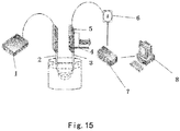
- the concentration measurement device includes a light source 1, an incident optical fiber 2, an optical fiber probe 3, a displacement device 4, a time gate device 5, an optical detector 6, a data collector 7 and a data processor 8.
- detection light is emitted from the light source 1 and enters the measured object through the incident optical fiber 2, and the optical detector 6 collects photons from the measured object through the optical fiber probe 3.
- the displacement device 4 controls the optical fiber probe to move to the benchmark position or the measurement position.
- the optical detector 6 measures the light intensity measurement value at the measurement position.
- the optical detector 6 measures the light intensity of the photons at the benchmark position as the light intensity reference value, wherein the sensitivity of the light intensity of the photons to the concentration change of the specific substance in the measured object is less than or equal to the preset threshold.
- the measurement position and the benchmark position are determined according to the change rates measured at a plurality of positions with different distances from the light source in the measured object, wherein the change rates are represented by change rates of the light intensity with the concentration of the specific substance in the measured object.
- the benchmark position may be a position where the change rate of the light intensity with the concentration of the specific substance is the smallest among the plurality of positions, and the measurement position may be a position where the change rate of the light intensity with the concentration of the specific substance is the largest among the plurality of positions.
- the benchmark position may be a position where the change rate of the light intensity with the concentration of the specific substance is zero.
- the data processor 8 uses the light intensity reference value to correct the light intensity measurement value, for example, it may obtain a benchmark light intensity reference value in a benchmark state, and use the benchmark light intensity reference value, the light intensity reference value, and the light intensity measurement value to correct the light intensity measurement value. According to experiments or numerical simulations, the corresponding relationship between the light intensity measurement value and the concentration of the specific substance may be obtained. Based on the relationship, the data processor 8 may use the corrected light intensity measurement value to obtain the concentration of the specific substance in the measured object.
- the light source 1 includes a short pulse light source.
- the optical detector 6 collects the photons, wherein the sensitivity of the photons to the concentration change of the specific substance is less than or equal to a preset threshold, for example, the sensitivity of the photons to the concentration change of the specific substance is equal to 0.
- the benchmark position may be a positional point, a positional area, or a circular ring centered on the light source
- the measured object may include blood
- the specific substance may be glucose
- the concentration measurement device may further include a light-converging device for converging the photons in the positional area onto the probe of the optical detector.
- the light-converging device may be a converging lens.
- the light intensity of photons that are insensitive to the concentration of the specific substance and the light intensity of photons that are more sensitive to the concentration of the specific substance are picked up by a time gate method to be used as the light intensity reference value and the light intensity measurement value, respectively.
- the light intensity measurement value is corrected by using the light intensity reference value, thereby reducing the interference of external factors on the measurement value, and reducing the system error.
- Example 1 Simulation experiment of a measurement method in which a reference value is measured at a single-point fixed optical length
- MCMLGO simulation is used for the medium of 2% intralipid-glucose solution.
- the glucose concentration is 0mg/dL, 500mg/dL, 1000mg/dL and 1500mg/dL.
- the number of photons emitted by the light source is 10 9 .
- Varied parameters light source energy fluctuation ⁇ 5% and ⁇ 10%.
- Measurement value at the measurement position, the sum of photons of all traveling optical lengths is selected as the light intensity measurement value.
- Reference value the number of photons which are emitted from the benchmark position and have the traveling optical length of the benchmark traveling optical length is used as the reference value. According to theoretical analysis, for the 2% intralipid-glucose solution, the benchmark traveling optical length of the photons emitted from the benchmark position is 4.0 ⁇ 0.2 mm, and the total number of the photons within the optical length range is used as the reference value.
- the change coefficient of the total number of photons at the benchmark traveling optical length ⁇ I 1 / I 0 , wherein I 0 is the number of photons at the benchmark traveling optical length before the light source power changes, and I 1 is the number of photons at the benchmark traveling optical length after the light source power changes.
- the measurement value I 2 which is affected by the fluctuation of the light source energy is corrected with ⁇ , and the corrected photon number is I 2 / ⁇ . It can be seen from Table 1 below that the corrected light intensity value is very close to the standard value.
- Table 1 Comparison of experimental results fluctuation rate of light source energy fluctuation rate of detection light energy before correction fluctuation rate of detection light energy after correction -10% 9.8% 1.1% -5% 4.4% 1.7% 5% 5.4% 0.39% 10% 10% 0.35%
- the change in the measurement value caused by the fluctuation of the light source energy before the correction and the change in the measurement value after the correction may be calculated. It can be seen that the fluctuation of the detected light energy is significantly reduced after the measurement value is corrected by the fluctuation coefficient obtained by the fluctuation of the total number of the photons of the benchmark traveling optical length.
- Example 2 Simulation experiment results of a measurement method in which a reference value is measured at a multi-point fixed optical length
- MCMLGO is used to simulate the traveling of photons in the tissue and the distribution of emission on the surface of the medium.
- the 2% intralipid-glucose solution is used as the medium, and the glucose concentration is 0mg/dL, 500mg/dL, 1000mg/dL and 1500mg/dL.
- the number of photons emitted from the light source is 10 9 .
- Varied parameters light source energy fluctuates within ⁇ 5% and ⁇ 10%, respectively.
- Measurement value the total number of photons which have a middle traveling optical length of 1.25mm and a traveling optical length range of 1.25 ⁇ 0.25mm is used as the measurement value.
- Reference value the total number of photons, which are emitted from the detection radius and have the traveling optical length that is equal to the benchmark traveling optical length, is used as the reference value.
- the benchmark traveling optical length is in a range of 1.25 ⁇ 0.25mm, and the total number of photons in the optical length range is used as the reference value.
- the measurement value which is affected by the fluctuation of the light source energy may be corrected by the change coefficient of the total number of photons at the benchmark traveling optical length. It can be seen from Table 2 below that the corrected light intensity value is very close to the standard value.
- Table 2 Comparison of experimental results fluctuation rate of light source energy fluctuation rate of detection light energy before correction fluctuation rate of detection light energy after correction -10% 9.87% 0.19% -5% 5.1% 0.33% 5% 4.6% 0.47% 10% 10.17% 0.37%
- the change in the measurement value caused by the fluctuation of the light source energy before the correction and the change in the measurement value after the correction may be calculated. It can be seen that the fluctuation of the detection light energy is significantly reduced after the measurement value is corrected by the fluctuation coefficient obtained by the fluctuation of the total number of the photons with the benchmark traveling optical length.
- the time gate detection method is applied to concentration measurement, and the time gate method is used to pick up the light intensity of photons that are insensitive to the concentration of the specific substance and the light intensity of photons that are more sensitive to the concentration of the specific substance as the measurement reference value and the measurement value, respectively.
- the reference value is used to correct the measurement value, and the background interference that is independent to the concentration of the measured object is deducted, so that the measurement value is closer to the true value, thereby reducing the system error.
Landscapes
- Physics & Mathematics (AREA)
- Health & Medical Sciences (AREA)
- Life Sciences & Earth Sciences (AREA)
- Pathology (AREA)
- General Health & Medical Sciences (AREA)
- Spectroscopy & Molecular Physics (AREA)
- General Physics & Mathematics (AREA)
- Immunology (AREA)
- Chemical & Material Sciences (AREA)
- Engineering & Computer Science (AREA)
- Analytical Chemistry (AREA)
- Biochemistry (AREA)
- Biomedical Technology (AREA)
- Molecular Biology (AREA)
- Medical Informatics (AREA)
- Biophysics (AREA)
- Surgery (AREA)
- Animal Behavior & Ethology (AREA)
- Public Health (AREA)
- Veterinary Medicine (AREA)
- Heart & Thoracic Surgery (AREA)
- Optics & Photonics (AREA)
- Hematology (AREA)
- Urology & Nephrology (AREA)
- Diabetes (AREA)
- Biotechnology (AREA)
- Cell Biology (AREA)
- Microbiology (AREA)
- Food Science & Technology (AREA)
- Medicinal Chemistry (AREA)
- Theoretical Computer Science (AREA)
- Mathematical Physics (AREA)
- Emergency Medicine (AREA)
- Measurement Of The Respiration, Hearing Ability, Form, And Blood Characteristics Of Living Organisms (AREA)
- Investigating Or Analysing Materials By Optical Means (AREA)
Abstract
Description
- This application claims priority of Chinese Patent Application No.
201810409248.1 - The present disclosure relates to the field of spectral detection technology, and in particular, to a method for correcting a light intensity measurement value and a concentration measurement device in which a reference value is measured at a time gate fixed optical length.
- Near-infrared spectroscopy technology has been widely applied to detect concentrations of substance components in many fields such as food or drug detection, air pollution detection, and water quality monitoring. The clinical application of near-infrared spectroscopy is also one of the current research hotpots, especially near-infrared non-invasive blood glucose detection. The near-infrared non-invasive blood glucose detection can not only realize timely, safe and painless self-monitoring of blood glucose concentration, but also does not require consumables, so that it can greatly reduce detection costs and has a very high clinical application value.
- Based on results and experience of various research groups at home and abroad, the current bottleneck restricting the accuracy and correctness of non-invasive human blood glucose concentration measurement is not due to the limitation of the signal-to-noise ratio of instrument hardware, but background change in the measurement process. How to eliminate an influence of background change and extract weak blood glucose change information from complex background change is a prerequisite for clinical application of non-invasive detection of human blood glucose concentration. Most of components in the blood, such as water, fat, protein, etc., have absorption in the near-infrared range, spectral peaks overlap with one another, factors such as biological activities and mood fluctuations of the organism and environmental influences will directly or indirectly affect the effective extraction of blood composition information, there are many and complex components in the blood and there are many and complex physiological factors, thus it is difficult to monitor the human blood glucose concentration in real time or measure it quantitatively at the current level of scientific research.
- With regard to defects in the related art, the present disclosure aims to provide a method for correcting a light intensity measurement value and a concentration measurement device in which a reference value is measured at a time gate fixed optical length, so as to solve at least one of the above problems.
- In an aspect, the present disclosure provides a method for correcting a light intensity measurement value, characterized in that, the method comprises: emitting detection light into a measured object; measuring a light intensity measurement value at a measurement position, and measuring light intensity of photons at a benchmark position as a light intensity reference value, wherein a sensitivity of the light intensity of photons to a concentration change of a specific substance in the measured object is less than or equal to a preset threshold, and a change rate of the light intensity at the measurement position with a concentration of the specific substance in the measured object is greater than a change rate of the light intensity at the benchmark position with the concentration of the specific substance; correcting the light intensity measurement value by using the light intensity reference value.
- Optionally, the method further includes: under different concentrations of the specific substance, by controlling the time when a short-pulse light source is turned on and the time when the short-pulse light source is turned off and controlling the time when an optical detector is turned on and the time when the optical detector is turned off, measuring light intensity of photons of different optical lengths at the benchmark position; determining a specific optical length of the photons, at which the sensitivity to the concentration change of the specific substance is less than or equal to the preset threshold.
- Optionally, the step of measuring light intensity of photons at the benchmark position comprises: measuring light intensity of the photons of the specific optical length.
- Optionally, the sensitivity of the light intensity of photons to the concentration change of the specific substance is equal to zero; and/or the benchmark position is a positional point, a positional area or a circular ring centered on a light source; and/or the measured object comprises blood; and/or the specific substance comprises glucose.
- Optionally, in response to that the benchmark position is the positional point, a probe of the optical detector is disposed at the positional point; in response to that the benchmark position is the positional area, photons in the positional area are converged to the probe by using a light-converging method.
- Optionally, in response to that the benchmark position is the positional point, the photons of the specific optical length are collected at the positional point by a probe of the optical detector; in response to that the benchmark position is the positional area, a lens is provided at the positional area to focus the photons in the positional area onto the probe.
- Optionally, the benchmark position is a position where the change rate of the light intensity with the concentration of the specific substance is the smallest among multiple positions that are at different distances from a light source in the measured object, and the measurement position is a position where the change rate of the light intensity with the concentration of the specific substance is the largest among the multiple positions; and/or the benchmark position is a position where the change rate of the light intensity with the concentration of the specific substance is equal to zero; and/or the step of correcting the light intensity measurement value by using the light intensity reference value comprises: obtaining a benchmark light intensity reference value in a benchmark state, and correcting the light intensity measurement value by using the benchmark light intensity reference value, the light intensity reference value and the light intensity measurement value.
- In another aspect, the present disclosure provides a concentration measurement device, characterized in that, the device comprises: a light source, an optical detector and a data processor, wherein, the light source is configured to emit detection light into a measured object; the optical detector is configured to measure a light intensity measurement value at a measurement position, and measure light intensity of photons at a benchmark position as a light intensity reference value, wherein a sensitivity of the light intensity of photons to a concentration change of a specific substance in the measured object is less than or equal to a preset threshold, and a change rate of the light intensity at the measurement position with the concentration of the specific substance in the measured object is greater than a change rate of the light intensity at the benchmark position with the concentration of the specific substance; the data processor is configured to correct the light intensity measurement value by using the light intensity reference value.
- Optionally, the light source is configured to emit the detection light into the measured object through an incident optical fiber; the optical detector is configured to collect photons from the measured object through an optical fiber probe.
- Optionally, the light source comprises a short-pulse light source, and the concentration measurement device further comprises a time gate device; and both the time when the short-pulse light source is turned on and the time when the short-pulse light source is turned off are controlled, and both the time when the optical detector is turned on and the time when the optical detector is turned off are controlled by the time gate device, so that the optical detector is configured to collect the photons, the sensitivity of which to the concentration change of the specific substance is less than or equal to the preset threshold.
- Optionally, the sensitivity of the light intensity of photons to the concentration change of the specific substance is equal to zero; and/or the benchmark position is a positional point, a positional area or a circular ring centered on the light source; and/or the measured object comprises blood; and/or the specific substance comprises glucose.
- Optionally, the benchmark position is a positional area; the concentration measurement device further comprises a light-converging device which is configured to converge photons in the positional area onto a probe of the optical detector.
- Optionally, the benchmark position is a position where the change rate of the light intensity with the concentration of the specific substance is the smallest among multiple positions that are at different distances from the light source in the measured object, and the measurement position is a position where the change rate of the light intensity with the concentration of the specific substance is the largest among the multiple positions; and/or the benchmark position is a position where the change rate of light intensity with the concentration of the specific substance is equal to zero; and/or the correcting the light intensity measurement value by using the light intensity reference value comprises: obtaining a benchmark light intensity reference value in a benchmark state, and correcting the light intensity measurement value by using the benchmark light intensity reference value, the light intensity reference value and the light intensity measurement value.
-
-
FIG. 1 is a schematic view showing the principle of the present disclosure; -
FIG. 2 shows a schematic view of the measurement method when a benchmark position is a positional point; -
FIG. 3 shows a schematic view of a change rate of light intensity of photons of different optical lengths at the benchmark position with concentration of specific substance in a measured object; -
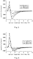
FIG. 4 shows a travelling optical length sensitivity distribution of 10% intralipid-glucose solution at a source-detector separation of 0.7 mm; -
FIG. 5 shows a travelling optical length sensitivity distribution of 10% intralipid-glucose solution at a source-detector separation of 0.8 mm; -
FIG. 6 shows a travelling optical length sensitivity distribution of 10% intralipid-glucose solution at a source-detector separation of 0.9 mm; -
FIG. 7 shows a travelling optical length sensitivity distribution of 10% intralipid-glucose solution at a source-detector separation of 1.0 mm; -
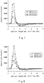
FIG. 8 shows a travelling optical length sensitivity distribution of 10% intralipid-glucose solution at a source-detector separation of 1.1 mm; -
FIG. 9 shows a travelling optical length sensitivity distribution of 10% intralipid-glucose solution at a source-detector separation of 1.2 mm; -
FIG. 10 shows a travelling optical length sensitivity distribution of 10% intralipid-glucose solution at a source-detector separation of 1.3 mm; -
FIG. 11 is a schematic view showing all diffusely-reflected photons which are emitted from an entire circular area with a light source as the center and a detection radius as the radius and have a traveling optical length of Li ; -
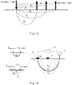
FIG. 12 is a graph showing a change of the total number of photons of the same traveling optical length within a radius of 10mm from the light source on a surface of the 10% intralipid-glucose solution with the glucose concentration; -
FIG. 13 is a schematic view showing the principle of a measurement method when the benchmark position is a positional area; -
FIG. 14 is a schematic view of a concentration measurement device in which a reference value is measured at a time gate fixed optical length; -
FIG. 15 is a schematic view of a concentration detection device according to embodiments of the present disclosure. - In order to make objectives, technical solutions and advantages of the present disclosure clearer, the present disclosure will be further described in detail below in conjunction with specific embodiments and with reference to the accompanying drawings.
- In process of proposing the present disclosure, the inventors have found that when an optical detection method is used to measure the concentration of a specific substance in the measured object, an optical signal received by an optical detector may be typically affected by background change. How to extract weak concentration information of the specific substance from complex background change is a problem that needs to be solved.
- The present disclosure provides a method for correcting a light intensity measurement value, characterized in that the method comprises: emitting detection light into a measured object; measuring a light intensity measurement value at a measurement position, and measuring light intensity of photons at a benchmark position as a light intensity reference value, wherein a sensitivity of the light intensity of photons to a concentration change of a specific substance in the measured object is less than or equal to a preset threshold, and a change rate of the light intensity at the measurement position with a concentration of the specific substance in the measured object is greater than a change rate of the light intensity at the benchmark position with the concentration of the specific substance; correcting the light intensity measurement value by using the light intensity reference value.
- According to some embodiments of the present disclosure, the light intensity of specific photons measured at the benchmark position is used as the light intensity reference value, and the light intensity measured at the measurement position is used as the light intensity measurement value. The background change in the measurement process is reflected in the light intensity reference value. The light intensity measurement value contains both concentration information of the specific substance and the background change information. By using the light intensity reference value to correct the light intensity measurement value, an influence of the background change in the measurement result may be effectively removed, and an accuracy of the measurement result may be improved.
-
FIG. 1 is a schematic view showing the principle of the present disclosure. - Specifically,
FIG. 1 is a schematic view showing traveling paths, traveling time, and path lengths of photons in a homogeneous medium. Photons travel in random paths in the skin tissue, but a large number of photons may show statistical characteristics of their traveling paths. It is found through research that the traveling paths of diffusely-reflected photons in the homogeneous medium are mainly concentrated in a banana-shaped area from an incident point of a light source to an exit position of the photons, as shown inFIG. 1 . The length of the photon's traveling path is the traveling optical length of the photon. Since only traveling time of the photon in the tissue may be detected in the actual detection, the traveling optical length may be converted into time by using t = Llc, wherein L is the photon traveling optical length, c is the speed at which the photon travels in the medium. For example, as shown inFIG. 1 , the optical length Ln corresponds to the traveling time tn, the optical length Lm corresponds to the traveling time tm, an optical length difference ΔL corresponds to a traveling time difference Δt, and an intermediate value between Ln and Lm corresponds to an intermediate value tcenter between tn and tm. In this way, photons of different optical lengths may be distinguished by the traveling time of photons. The diffusely-reflected photons of different optical lengths (i.e., different traveling time) collected by an optical detector probe are distinguished by a time gate device. Sensitivities of the photons, which reach the probe and undergo different traveling optical lengths, to concentration change of the specific substance is analyzed. The light intensity of the photons with low sensitivity to the concentration change of the specific substance (for example, the sensitivity is equal to 0) is measured and used as the light intensity reference value. The light intensity reference value is used to correct the light intensity measurement value. For example, a benchmark light intensity reference value in a benchmark state is obtained. The benchmark light intensity reference value, the light intensity reference value, and the light intensity measurement value are used to correct the light intensity measurement value, so that the measurement value is closer to the true value, thereby reducing measurement error. For example, the benchmark light intensity reference value is I0, the light intensity reference value is I1, and the light intensity measurement value is I2, and the corrected light intensity measurement value is I2 ∗I0/I1. - According to the embodiments of the present disclosure, before and after the concentration of the specific substance in the measured object is changed, the light intensity may be measured at multiple positions which are at different distances from the light source. One of the multiple positions, where the change rate of the light intensity with the concentration of the specific substance is the smallest, may be used as the benchmark position, and one of the multiple positions, where the change rate of the light intensity with the concentration of the specific substance is the largest, may be used as the measurement position. When the detection light emitted by the light source enters the measured object, the change rate of the light intensity measured at different positions of the measured object varies with the concentration of the specific substance. One of the multiple positions, where the change rate of the light intensity with the concentration of the specific substance is the smallest, may be used as the benchmark position. According to the embodiments of the present disclosure, a position, where the change rate of the light intensity with the concentration of the specific substance is equal to zero, may be used as the benchmark position.
- Further, a sensitivity of the light intensity of photons measured at the benchmark position to the concentration change of the specific substance is lower than a preset threshold, and the light intensity of photons may be used as the light intensity reference value. According to the embodiments of the present disclosure, the preset threshold may be set according to actual needs, for example, it may be set to a value very close to zero, or set to zero. For example, under different concentrations of the specific substance, by controlling both the time when a short-pulse light source is turned on and turned off and the time when an optical detector is turned on and turned off, the light intensity of photons of different optical lengths (i.e., different traveling time) may be measured at the benchmark position, so as to determine the specific optical length of the photons, the sensitivity of which to the concentration change of the specific substance is less than or equal to the preset threshold. In actual measurement, the light intensity of the photons of the specific optical length measured at the benchmark position is used as the light intensity reference value.
- Compared with collecting photons of all traveling optical lengths when detecting at a certain position, the fixed optical length detection only extracts photons of a certain traveling optical length, thereby eliminating other irrelevant light. Although the light intensity becomes weak, a dynamic detection range of useful signal may be increased by a larger magnification to facilitate the extraction of the useful signal.
- According to the embodiments of the present disclosure, the benchmark position is a positional point or a positional area.
- When the benchmark position is a positional point, under ideal conditions (infinitely-thin light source is incident vertically and all diffusely-reflected photons are collected at the measurement position), when a source-detector separation (SDS) satisfies SDS=ρ, according to the traveling optical length L=ct, wherein c is a traveling speed of photons in the medium, t is a traveling time, and the traveling optical length distribution function of diffuse-reflection light energy Rf at the probe may be obtained as:

- Based on the traveling optical length distribution function of the diffuse-reflection light energy Rf at the probe, it can be deduced that the detection sensitivity of the photons of the specific optical length at the benchmark position is equal to 0, that is, the light intensity of the photons of the specific optical length measured at the benchmark position is used as the light intensity reference value. The derivation process may be performed as follows.
- As optical parameters of the medium change, according to research results of the inventors of the present disclosure on a change rule of the optical parameters with glucose concentration, the detection sensitivity of the photons which have a traveling optical length of L is obtained:

- Through calculation, it may be obtained as follows:

- Wherein ρ n represents any SDS, µa = µao + (ε g - 6.1494εw )Cg , K=8.5×10⁻⁵ µs = µ s0 -2W(λ)µ s0 Cg, g=g 0 +8.5×10 -5 Cg, G=εg-kwεw , µ's=(1 - g)µs, εg is the molar absorption coefficient of glucose, εw is the molar absorption coefficient of water, W(λ) is the change factor of the scattering coefficient at different wavelengths.
-
FIG. 2 shows a schematic view of the measurement method when the benchmark position is a positional point. - As shown in
FIG. 2 , p is the distance between the light source and the benchmark position. I incidence is the detection light emitted by the light source and incident on the measured object, Iemission is the emitted light at the benchmark position, and the optical detector probe is disposed at the benchmark position to detect the emitted light. At the benchmark position, the sensitivity of the total emitted light of different traveling optical lengths to the concentration change of the specific substance is equal to 0, and there are photons of a special optical length L at the benchmark position, the sensitivity of the photons of a special optical length L to the concentration change of the specific substance is also equal to 0. Only the photons of the optical length L detected at the benchmark position are extracted as the light intensity reference value by the time gate method, thereby improving the accuracy of the detected light intensity. -
FIG. 3 shows a schematic view of the change rate of the light intensity of photons of different optical lengths at the benchmark position with the concentration of the specific substance in the measured object. - As shown in
FIG. 3 , at the benchmark position of ρ=2mm, the change rate of the light intensity of the photons of an optical length of about 5.6mm with the concentration of the specific substance in the measured object is equal to 0, that is, the sensitivity of the photons to the concentration change of the specific substance is equal to 0. Therefore, the light intensity of the photons of the optical length may be measured as the light intensity reference value. -
FIG. 4 to FIG. 10 show the detection sensitivity distributions of 10% intralipid-glucose solution at different source-detector separations. As shown inFIG. 4-FIG.10 , a simulation is performed as for the 10% intralipid-glucose solution under the light source of 1200nm. The traveling optical length sensitivity distributions are simulated when the source-detector separation is in the range of 0.7-1.3 mm. The abscissa is the optical length, and the ordinate is the sensitivity. It can be seen from the figures that at a certain source-detector separation, there is a certain optical length, at which the sensitivity to the concentration change of glucose is equal to 0. - According to the embodiments of the present disclosure, the benchmark position may also be a positional area, such as a circular ring centered on the light source. The following derivation aims to prove that when the benchmark position is an area, there is also an optical length in which the sensitivity to the concentration change of glucose is equal to 0.
-
FIG. 11 is a schematic view showing all diffusely-reflected photons which are emitted from an entire circular area with the light source as the center and the detection radius as the radius and have a traveling optical length of Li. - As shown in
FIG. 11 , the total number of photons picked up in each traveling optical length may be expressed as

- By integrating the source-detector separations, the sum of the number of photons corresponding to certain traveling time emitted at all source-detector separations may be obtained as:


- When counting photons within 3σ, there are:
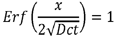


- Taking the derivative of all diffusely-reflected photons under a certain traveling optical length to the glucose concentration, the sensitivity sl of all photons to the glucose concentration change under the traveling optical length may be calculated as:





- According to the influence of glucose concentration on optical parameters:


- Monte Carlo simulation may be used to calculate the traveling of photons in glucose solutions of 0 mg/dL, 500 mg/dL, 1000 mg/dL, and 1500 mg/dL prepared from 10% intralipid solution under 1280nm light source. The sum of the number of diffusely-reflected photons under different traveling lengths is obtained. In order to count all the diffusely-reflected photons, the selected detection radius is 10 mm, the traveling optical length range is 0.5mm, and the number of light source photons is 109.
-
FIG. 12 is a graph showing a change of the sum of the number of photons of the same traveling optical length within a radius of 10mm from the light source on the surface of the 10% intralipid-glucose solution with the glucose concentration. - As shown in
FIG 12 , in the case of the 1280nm light source, when the glucose concentration changes by 10%, the difference between the sum of the number of photons and the number of photons obtained in the case of 0mg/dL intralipid-glucose solution is calculated, wherein the sum of the number of photons are as for different traveling optical lengths emitted from a region within a radius of 10mm from the light source on the surface of the intralipid-glucose solution medium. It can be seen that there is an intersection point at the position where the traveling optical length is 4.3mm. On the left side of the intersection point, the number of diffusely-reflected photons is negatively correlated with the glucose concentration change, and on the right side of the intersection point, the number of diffusely-reflected photons is positively correlated with the glucose concentration change. The total number of diffusely-reflected photons of a traveling optical length of 4.3mm within a radius of 10mm from the light source is approximately independent of the glucose concentration change. It can be seen that the benchmark position may be a positional area from the light source, in this positional area, there is an optical length with a sensitivity of 0, that is, 4.3mm. -
FIG. 13 is a schematic view showing the principle of the measurement method when the benchmark position is the positional area. - As shown in
FIG. 13 , when the source-detector separations are ρ1, ρ2, and ρ3, there are special optical lengths L in which the sensitivity to the concentration change of the measured object is equal to 0. All photons of the optical length of L within a certain source-detector separation range are extracted by the time gate method, thereby increasing the detected light intensity, and improving the signal-to-noise ratio and the detection accuracy. For example, the benchmark position may be set as an area including three positions with distances of ρ1, ρ2, and ρ3 to the light source, or the benchmark position may be set as a circular ring with the light source as the center and any distance of ρ1, ρ2, or ρ3 as the radius, or the benchmark position may be set as a circular ring with the light source as the center, ρ1 as the inner radius, and ρ3 as the outer radius. - Compared with the situation where the positional point is used as the benchmark position, the positional area is used as the benchmark position, the requirement for the accuracy of the probe positioning is low. Small deviations will not cause excessive loss of effectiveness when using the light intensity reference value to correct the light intensity measurement value, so as to avoid introducing measurement errors. By extending the benchmark position into a band, the applicability of the method of the present disclosure may be improved.
-
FIG. 14 is a schematic view of a concentration measurement device in which a reference concentration is measured at a time gate fixed optical length. - As shown in
FIG. 14 , the concentration measurement device includes alight source 1, acontrol part 12, and a timegate control part 13. Thecontrol part 12 controls the time when the light source is turned on and the time when the light source is turned off, and the timegate control part 13 controls the time when the optical detector is turned on and the time when the optical detector is turned off, so that the optical detector only measures the intensity of the photons of the specific optical length as the light intensity reference value. Thecontrol part 12 corrects the light intensity measurement value obtained at themeasurement position 9 with the light intensity reference value, and the concentration of the specific substance in the measured object may be obtained based on the corrected light intensity measurement value. - As shown in
FIG. 14 , when the benchmark position is a positional point, the probe of the optical detector is disposed at the positional point, and the photons of the specific optical length L is collected by the optical fiber probe. When the benchmark position is a positional area, the photons of the specific optical length L in the positional area is converged to the probe by using a light-converging method. For example, a lens may be embedded on a surface of the light probe to converge the light, or a ring-shaped condenser lens 11 (a cross-section of the ring-shapedcondenser lens 11 is shown inFIG. 14 ) is used to converge the light onto the probe. - As for different measured objects, traveling optical lengths at which the sensitivity is equal to 0 may be different. The time when the light source is turned on and the time when the light source is turned off may be adjusted, and the time when the optical detector is turned on and the time when the optical detector is turned off may be also adjusted, so as to adjust the traveling time t of the received photons, thereby obtaining the traveling optical lengths at which the sensitivity is equal to 0 as for different measured objects. For example, if the photons of the specific optical length range of l0 + Δl are collected, the time when the light source is turned on and the time when the light source is turned off may be adjusted, and the time when the optical detector is turned on and the time when the optical detector is turned off may be also adjusted, so as to only collect the photons with the traveling time of l0lc ∼ (lo + Δl/)c in the measured object, wherein c is the traveling speed of light in the measured object, and Δl/c is the opening width. In this way, the method may be adapted to the measurement needs of different individuals without manually or mechanically adjusting the distance of the benchmark position or designing a variety of fiber optic probes.
-
FIG. 15 is a schematic view of a concentration detection device according to the embodiments of the present disclosure. - As shown in
FIG. 15 , the concentration measurement device includes alight source 1, an incidentoptical fiber 2, anoptical fiber probe 3, adisplacement device 4, atime gate device 5, anoptical detector 6, adata collector 7 and adata processor 8. Wherein, detection light is emitted from thelight source 1 and enters the measured object through the incidentoptical fiber 2, and theoptical detector 6 collects photons from the measured object through theoptical fiber probe 3. Thedisplacement device 4 controls the optical fiber probe to move to the benchmark position or the measurement position. Theoptical detector 6 measures the light intensity measurement value at the measurement position. By controlling the time when the light source is turned on and the time when the light source is turned off, and by controlling the time when theoptical detector 6 is turned on and the time when theoptical detector 6 is turned off by thetime gate device 5, theoptical detector 6 measures the light intensity of the photons at the benchmark position as the light intensity reference value, wherein the sensitivity of the light intensity of the photons to the concentration change of the specific substance in the measured object is less than or equal to the preset threshold. The measurement position and the benchmark position are determined according to the change rates measured at a plurality of positions with different distances from the light source in the measured object, wherein the change rates are represented by change rates of the light intensity with the concentration of the specific substance in the measured object. The benchmark position may be a position where the change rate of the light intensity with the concentration of the specific substance is the smallest among the plurality of positions, and the measurement position may be a position where the change rate of the light intensity with the concentration of the specific substance is the largest among the plurality of positions. Alternatively, the benchmark position may be a position where the change rate of the light intensity with the concentration of the specific substance is zero. Thedata processor 8 uses the light intensity reference value to correct the light intensity measurement value, for example, it may obtain a benchmark light intensity reference value in a benchmark state, and use the benchmark light intensity reference value, the light intensity reference value, and the light intensity measurement value to correct the light intensity measurement value. According to experiments or numerical simulations, the corresponding relationship between the light intensity measurement value and the concentration of the specific substance may be obtained. Based on the relationship, thedata processor 8 may use the corrected light intensity measurement value to obtain the concentration of the specific substance in the measured object. - According to the embodiments of the present disclosure, the
light source 1 includes a short pulse light source. By controlling the time when the short pulse light source is turned on and the time when the short pulse light source is turned off, and by controlling the time when theoptical detector 6 is turned on and the time when theoptical detector 6 is turned off by thetime gate device 5, theoptical detector 6 collects the photons, wherein the sensitivity of the photons to the concentration change of the specific substance is less than or equal to a preset threshold, for example, the sensitivity of the photons to the concentration change of the specific substance is equal to 0. - According to the embodiments of the present disclosure, the benchmark position may be a positional point, a positional area, or a circular ring centered on the light source, the measured object may include blood, and the specific substance may be glucose.
- According to the embodiments of the present disclosure, when the benchmark position is a positional area, the concentration measurement device may further include a light-converging device for converging the photons in the positional area onto the probe of the optical detector. The light-converging device may be a converging lens.
- In the embodiments of the present disclosure, the light intensity of photons that are insensitive to the concentration of the specific substance and the light intensity of photons that are more sensitive to the concentration of the specific substance are picked up by a time gate method to be used as the light intensity reference value and the light intensity measurement value, respectively. The light intensity measurement value is corrected by using the light intensity reference value, thereby reducing the interference of external factors on the measurement value, and reducing the system error.
- Hereinafter, in conjunction with specific examples, effects of the method for correcting the light intensity measurement value and the concentration measurement device in which the reference concentration is measured at a time gate fixed optical length according to the present disclosure will be described in further detail.
- Simulation parameters: MCMLGO simulation is used for the medium of 2% intralipid-glucose solution. The glucose concentration is 0mg/dL, 500mg/dL, 1000mg/dL and 1500mg/dL. In the case of 1200nm light source, the number of photons emitted by the light source is 109.
- Varied parameters: light source energy fluctuation ±5% and ±10%.
- Measurement value: at the measurement position, the sum of photons of all traveling optical lengths is selected as the light intensity measurement value.
- Reference value: the number of photons which are emitted from the benchmark position and have the traveling optical length of the benchmark traveling optical length is used as the reference value. According to theoretical analysis, for the 2% intralipid-glucose solution, the benchmark traveling optical length of the photons emitted from the benchmark position is 4.0±0.2 mm, and the total number of the photons within the optical length range is used as the reference value.
- When the light source power changes by ±5% and ±10%, the change coefficient of the total number of photons at the benchmark traveling optical length η = I1 /I 0, wherein I0 is the number of photons at the benchmark traveling optical length before the light source power changes, and I 1 is the number of photons at the benchmark traveling optical length after the light source power changes. The measurement value I 2 which is affected by the fluctuation of the light source energy is corrected with η, and the corrected photon number is I 2/η. It can be seen from Table 1 below that the corrected light intensity value is very close to the standard value.
Table 1 Comparison of experimental results fluctuation rate of light source energy fluctuation rate of detection light energy before correction fluctuation rate of detection light energy after correction -10% 9.8% 1.1% -5% 4.4% 1.7% 5% 5.4% 0.39% 10% 10% 0.35% - Taking the 1000mg/dl intralipid-glucose solution as an example, the change in the measurement value caused by the fluctuation of the light source energy before the correction and the change in the measurement value after the correction may be calculated. It can be seen that the fluctuation of the detected light energy is significantly reduced after the measurement value is corrected by the fluctuation coefficient obtained by the fluctuation of the total number of the photons of the benchmark traveling optical length.
- Simulation parameters: MCMLGO is used to simulate the traveling of photons in the tissue and the distribution of emission on the surface of the medium. The 2% intralipid-glucose solution is used as the medium, and the glucose concentration is 0mg/dL, 500mg/dL, 1000mg/dL and 1500mg/dL. In the case of 1200nm light source, the number of photons emitted from the light source is 109.
- Varied parameters: light source energy fluctuates within ±5% and ±10%, respectively.
- Measurement value: the total number of photons which have a middle traveling optical length of 1.25mm and a traveling optical length range of 1.25±0.25mm is used as the measurement value.
- Reference value: the total number of photons, which are emitted from the detection radius and have the traveling optical length that is equal to the benchmark traveling optical length, is used as the reference value. According to theoretical analysis, for a 2% intralipid-glucose solution, the benchmark traveling optical length is in a range of 1.25±0.25mm, and the total number of photons in the optical length range is used as the reference value.
- When the light source power changes by ±5% and ±10%, the measurement value which is affected by the fluctuation of the light source energy may be corrected by the change coefficient of the total number of photons at the benchmark traveling optical length. It can be seen from Table 2 below that the corrected light intensity value is very close to the standard value.
Table 2 Comparison of experimental results fluctuation rate of light source energy fluctuation rate of detection light energy before correction fluctuation rate of detection light energy after correction -10% 9.87% 0.19% -5% 5.1% 0.33% 5% 4.6% 0.47% 10% 10.17% 0.37% - Taking the 1000mg/dl intralipid-glucose solution as an example, the change in the measurement value caused by the fluctuation of the light source energy before the correction and the change in the measurement value after the correction may be calculated. It can be seen that the fluctuation of the detection light energy is significantly reduced after the measurement value is corrected by the fluctuation coefficient obtained by the fluctuation of the total number of the photons with the benchmark traveling optical length.
- Therefore, in the method for correcting the light intensity measurement value and the concentration measurement device in which the reference value is measured at the time gate fixed optical length according to the present disclosure, the time gate detection method is applied to concentration measurement, and the time gate method is used to pick up the light intensity of photons that are insensitive to the concentration of the specific substance and the light intensity of photons that are more sensitive to the concentration of the specific substance as the measurement reference value and the measurement value, respectively. The reference value is used to correct the measurement value, and the background interference that is independent to the concentration of the measured object is deducted, so that the measurement value is closer to the true value, thereby reducing the system error.
- In the specific embodiments described above, objectives, technical solutions and beneficial effects of the present disclosure are described in detail. It should be understood that the above descriptions are only specific embodiments of the present disclosure and are not intended to limit the present disclosure. Any modification, equivalent replacement, improvement and the like within the spirit and principle of the present disclosure shall be included in the protection scope of the present disclosure.
| 1- light source | 2-incident fiber |
| 3-fiber probe | 4-displacement device |
| 5-time gate device | 6-optical detector |
| 7-data collector | 8-data processor |
| 9-measurement position | 10-benchmark position |
| 11-condenser lens | 12-control part |
| 13-time gate control part |
Claims (13)
- A method for correcting a light intensity measurement value, characterized in that, the method comprises:emitting detection light into a measured object;measuring a light intensity measurement value at a measurement position, and measuring light intensity of photons at a benchmark position as a light intensity reference value, wherein a sensitivity of the light intensity of photons to a concentration change of a specific substance in the measured object is less than or equal to a preset threshold, and a change rate of the light intensity at the measurement position with a concentration of the specific substance in the measured object is greater than a change rate of the light intensity at the benchmark position with the concentration of the specific substance;correcting the light intensity measurement value by using the light intensity reference value.
- The method according to claim 1, characterized in that, the method further comprises:under different concentrations of the specific substance, by controlling the time when a short-pulse light source is turned on and the time when the short-pulse light source is turned off and controlling the time when an optical detector is turned on and the time when the optical detector is turned off, measuring light intensity of photons of different optical lengths at the benchmark position;determining a specific optical length of the photons, at which the sensitivity to the concentration change of the specific substance is less than or equal to the preset threshold.
- The method according to claim 2, characterized in that, the step of measuring light intensity of photons at the benchmark position comprises: measuring light intensity of the photons of the specific optical length.
- The method according to claim 1, characterized in that,
the sensitivity of the light intensity of photons to the concentration change of the specific substance is equal to zero; and/or
the benchmark position is a positional point, a positional area or a circular ring centered on a light source; and/or
the measured object comprises blood; and/or
the specific substance comprises glucose. - The method according to claim 4, characterized in that,
in response to that the benchmark position is the positional point, a probe of the optical detector is disposed at the positional point;
in response to that the benchmark position is the positional area, photons in the positional area are converged to the probe by using a light-converging method. - The method according to claim 4, characterized in that,
in response to that the benchmark position is the positional point, the photons of the specific optical length are collected at the positional point by a probe of the optical detector;
in response to that the benchmark position is the positional area, a lens is provided at the positional area to focus the photons in the positional area onto the probe. - The method according to claim 1, characterized in that,
the benchmark position is a position where the change rate of the light intensity with the concentration of the specific substance is the smallest among multiple positions that are at different distances from a light source in the measured object, and the measurement position is a position where the change rate of the light intensity with the concentration of the specific substance is the largest among the multiple positions; and/or
the benchmark position is a position where the change rate of the light intensity with the concentration of the specific substance is equal to zero; and/or
the step of correcting the light intensity measurement value by using the light intensity reference value comprises: obtaining a benchmark light intensity reference value in a benchmark state, and correcting the light intensity measurement value by using the benchmark light intensity reference value, the light intensity reference value and the light intensity measurement value. - A concentration measurement device, characterized in that, the device comprises: a light source, an optical detector and a data processor, wherein,
the light source is configured to emit detection light into a measured object;
the optical detector is configured to measure a light intensity measurement value at a measurement position, and measure light intensity of photons at a benchmark position as a light intensity reference value, wherein a sensitivity of the light intensity of photons to a concentration change of a specific substance in the measured object is less than or equal to a preset threshold, and a change rate of the light intensity at the measurement position with the concentration of the specific substance in the measured object is greater than a change rate of the light intensity at the benchmark position with the concentration of the specific substance;
the data processor is configured to correct the light intensity measurement value by using the light intensity reference value. - The device according to claim 8, characterized in that,
the light source is configured to emit the detection light into the measured object through an incident optical fiber;
the optical detector is configured to collect photons from the measured object through an optical fiber probe. - The device according to claim 8, characterized in that,
the light source comprises a short-pulse light source, and the concentration measurement device further comprises a time gate device; and
both the time when the short-pulse light source is turned on and the time when the short-pulse light source is turned off are controlled, and both the time when the optical detector is turned on and the time when the optical detector is turned off are controlled by the time gate device, so that the optical detector is configured to collect the photons, the sensitivity of which to the concentration change of the specific substance is less than or equal to the preset threshold. - The device according to claim 8, characterized in that,
the sensitivity of the light intensity of photons to the concentration change of the specific substance is equal to zero; and/or
the benchmark position is a positional point, a positional area or a circular ring centered on the light source; and/or
the measured object comprises blood; and/or
the specific substance comprises glucose. - The device according to claim 8, characterized in that,
the benchmark position is a positional area;
the concentration measurement device further comprises a light-converging device which is configured to converge photons in the positional area onto a probe of the optical detector. - The device according to claim 8, characterized in that,
the benchmark position is a position where the change rate of the light intensity with the concentration of the specific substance is the smallest among multiple positions that are at different distances from the light source in the measured object, and the measurement position is a position where the change rate of the light intensity with the concentration of the specific substance is the largest among the multiple positions; and/or
the benchmark position is a position where the change rate of light intensity with the concentration of the specific substance is equal to zero; and/or
the correcting the light intensity measurement value by using the light intensity reference value comprises: obtaining a benchmark light intensity reference value in a benchmark state, and correcting the light intensity measurement value by using the benchmark light intensity reference value, the light intensity reference value and the light intensity measurement value.
Applications Claiming Priority (2)
| Application Number | Priority Date | Filing Date | Title |
|---|---|---|---|
| CN201810409248.1A CN110411947B (en) | 2018-04-28 | 2018-04-28 | Method and device for measuring concentration by fixed optical path reference of time gate |
| PCT/CN2019/093776 WO2019206345A1 (en) | 2018-04-28 | 2019-06-28 | Light intensity measurement value correction method, and time gate optical path reference concentration measurement apparatus |
Publications (3)
| Publication Number | Publication Date |
|---|---|
| EP3783338A1 true EP3783338A1 (en) | 2021-02-24 |
| EP3783338A4 EP3783338A4 (en) | 2022-05-04 |
| EP3783338B1 EP3783338B1 (en) | 2023-10-18 |
Family
ID=68294914
Family Applications (1)
| Application Number | Title | Priority Date | Filing Date |
|---|---|---|---|
| EP19793332.8A Active EP3783338B1 (en) | 2018-04-28 | 2019-06-28 | Light intensity measurement value correction method, and time gate optical path reference concentration measurement apparatus |
Country Status (4)
| Country | Link |
|---|---|
| US (1) | US11371934B2 (en) |
| EP (1) | EP3783338B1 (en) |
| CN (1) | CN110411947B (en) |
| WO (1) | WO2019206345A1 (en) |
Families Citing this family (5)
| Publication number | Priority date | Publication date | Assignee | Title |
|---|---|---|---|---|
| CN108814550A (en) * | 2018-04-16 | 2018-11-16 | 北京工业大学 | A kind of near infrared spectrum tomography rebuilding method neural network based |
| CN112557663A (en) * | 2019-09-25 | 2021-03-26 | 百略医学科技股份有限公司 | Test strip and method for manufacturing test strip |
| CN115153533B (en) * | 2020-02-26 | 2024-10-22 | 先阳科技有限公司 | A method, device, system and wearable device for non-invasive detection of tissue components |
| CN115281667B (en) * | 2020-02-26 | 2024-12-03 | 先阳科技有限公司 | Noninvasive detection method, noninvasive detection device, noninvasive detection system and noninvasive detection wearable equipment for tissue components |
| CN119574488B (en) * | 2025-02-06 | 2025-05-13 | 南昌大学 | Intelligent protein quality detection method and system based on spectral analysis |
Family Cites Families (10)
| Publication number | Priority date | Publication date | Assignee | Title |
|---|---|---|---|---|
| NZ330905A (en) * | 1996-01-26 | 2000-03-27 | Roche Diagnostics Gmbh | Process and device for determining an analyte contained in a scattering matrix |
| EP1585440A1 (en) * | 2003-01-13 | 2005-10-19 | Glucon Inc. | Photoacoustic assay method and apparatus |
| CN1699973B (en) * | 2005-04-28 | 2012-05-09 | 天津先阳科技发展有限公司 | Method for realizing concentration measurement by employing flotation benchmarks |
| CN100512752C (en) | 2007-01-12 | 2009-07-15 | 天津市先石光学技术有限公司 | Optical distance optional type atraumatic human body component measuring method and apparatus therefor |
| CN101292875B (en) * | 2008-06-06 | 2010-07-14 | 天津市先石光学技术有限公司 | Method for measuring component concentration with reference wavelength |
| EP2844980A1 (en) * | 2012-04-30 | 2015-03-11 | Mayo Foundation For Medical Education And Research | Method and apparatus for selecting wavelengths for optimal measurement of a property of a molecular analyte |
| CN105136690B (en) * | 2014-05-28 | 2018-07-24 | 天津先阳科技发展有限公司 | Diffuse spectrum data processing method, modeling method, prediction technique and processing unit |
| JP6630061B2 (en) * | 2014-05-28 | 2020-01-15 | 天津先陽科技発展有限公司 | Method and apparatus for processing spread spectrum data |
| CN105510238B (en) * | 2014-09-28 | 2019-04-05 | 天津先阳科技发展有限公司 | Processing, modeling, prediction technique and the processing unit of multiposition diffusion spectroscopic data |
| CN105987881B (en) * | 2015-03-05 | 2019-07-23 | 天津先阳科技发展有限公司 | Spectroscopic data disturbance restraining method, modeling method, prediction technique and processing unit |
-
2018
- 2018-04-28 CN CN201810409248.1A patent/CN110411947B/en active Active
-
2019
- 2019-06-28 US US17/050,530 patent/US11371934B2/en active Active
- 2019-06-28 EP EP19793332.8A patent/EP3783338B1/en active Active
- 2019-06-28 WO PCT/CN2019/093776 patent/WO2019206345A1/en not_active Ceased
Also Published As
| Publication number | Publication date |
|---|---|
| CN110411947B (en) | 2022-07-22 |
| EP3783338B1 (en) | 2023-10-18 |
| CN110411947A (en) | 2019-11-05 |
| US11371934B2 (en) | 2022-06-28 |
| EP3783338A4 (en) | 2022-05-04 |
| WO2019206345A1 (en) | 2019-10-31 |
| US20210131956A1 (en) | 2021-05-06 |
Similar Documents
| Publication | Publication Date | Title |
|---|---|---|
| EP3783338B1 (en) | Light intensity measurement value correction method, and time gate optical path reference concentration measurement apparatus | |
| EP0876596B1 (en) | Process and device for determining an analyte contained in a scattering matrix | |
| EP0707826B1 (en) | Method and device for determining glucose in biologic medium | |
| US10288567B2 (en) | Time-resolved laser-induced fluorescence spectroscopy systems and uses thereof | |
| EP2046190B1 (en) | Measure of glucose concentration in pulsating blood | |
| EP1013219B1 (en) | Living body information measuring apparatus, living body information measuring method, body fat measuring apparatus, body fat measuring method, and program recording medium | |
| CN104146714B (en) | Organizer local oxyhemoglobin saturation variation topology imaging device and method | |
| JP4717949B2 (en) | Component concentration measurement method | |
| US20040015060A1 (en) | Measurement of body compounds | |
| US9259486B2 (en) | Method and system for calculating a quantification indicator for quantifying a dermal reaction on the skin of a living being | |
| CN113208586A (en) | Noninvasive blood glucose rapid diagnosis differential Raman spectroscopy system | |
| CN111599470A (en) | A method for improving the accuracy of near-infrared non-invasive blood glucose detection | |
| CN101696931B (en) | Method and device for nondestructively testing material concentration | |
| Yuan et al. | Research on improving the accuracy of near infrared non-invasive hemoglobin detection | |
| DE102006018862A1 (en) | Device for the spectroscopic analysis of a gas | |
| JP2004286475A (en) | Apparatus for measuring glucose concentration | |
| JP3836086B2 (en) | Optical component measuring device | |
| Yang et al. | Reference point of floating-reference method for blood glucose sensing | |
| JP2013050376A (en) | Measuring device for functional state of biological tissue and method of the same | |
| CN111329492B (en) | Noninvasive blood lipid detection device and detection method based on near infrared spectrum | |
| KR102335211B1 (en) | Method and apparatus for measuring blood component using self-reference point establishment | |
| US20080227130A1 (en) | Method for detecting exposure to ionizing radiation | |
| CN223112172U (en) | Gamma knife radiotherapy dosage collection system | |
| JP2013134243A (en) | Measurement apparatus | |
| JP2012152412A (en) | Biological light measuring apparatus |
Legal Events
| Date | Code | Title | Description |
|---|---|---|---|
| STAA | Information on the status of an ep patent application or granted ep patent |
Free format text: STATUS: THE INTERNATIONAL PUBLICATION HAS BEEN MADE |
|
| PUAI | Public reference made under article 153(3) epc to a published international application that has entered the european phase |
Free format text: ORIGINAL CODE: 0009012 |
|
| STAA | Information on the status of an ep patent application or granted ep patent |
Free format text: STATUS: REQUEST FOR EXAMINATION WAS MADE |
|
| 17P | Request for examination filed |
Effective date: 20201120 |
|
| AK | Designated contracting states |
Kind code of ref document: A1 Designated state(s): AL AT BE BG CH CY CZ DE DK EE ES FI FR GB GR HR HU IE IS IT LI LT LU LV MC MK MT NL NO PL PT RO RS SE SI SK SM TR |
|
| AX | Request for extension of the european patent |
Extension state: BA ME |
|
| XX | Miscellaneous (additional remarks) |
Free format text: THE FILING DATE OF THE INTERNATIONAL APPLICATION IS WITHIN TWO MONTHS FROM THE DATE OF EXPIRATION OF THE PRIORITY PERIOD (R. 26BIS.3 PCT). |
|
| DAV | Request for validation of the european patent (deleted) | ||
| DAX | Request for extension of the european patent (deleted) | ||
| A4 | Supplementary search report drawn up and despatched |
Effective date: 20220405 |
|
| RIC1 | Information provided on ipc code assigned before grant |
Ipc: G01N 21/49 20060101ALI20220330BHEP Ipc: G01N 21/47 20060101ALI20220330BHEP Ipc: G01N 21/27 20060101ALI20220330BHEP Ipc: A61B 5/1455 20060101ALI20220330BHEP Ipc: A61B 5/00 20060101ALI20220330BHEP Ipc: G01N 21/359 20140101ALI20220330BHEP Ipc: A61B 5/145 20060101ALI20220330BHEP Ipc: G01N 21/25 20060101ALI20220330BHEP Ipc: G01N 21/35 20140101AFI20220330BHEP |
|
| GRAP | Despatch of communication of intention to grant a patent |
Free format text: ORIGINAL CODE: EPIDOSNIGR1 |
|
| STAA | Information on the status of an ep patent application or granted ep patent |
Free format text: STATUS: GRANT OF PATENT IS INTENDED |
|
| INTG | Intention to grant announced |
Effective date: 20230531 |
|
| GRAS | Grant fee paid |
Free format text: ORIGINAL CODE: EPIDOSNIGR3 |
|
| GRAA | (expected) grant |
Free format text: ORIGINAL CODE: 0009210 |
|
| STAA | Information on the status of an ep patent application or granted ep patent |
Free format text: STATUS: THE PATENT HAS BEEN GRANTED |
|
| P01 | Opt-out of the competence of the unified patent court (upc) registered |
Effective date: 20230810 |
|
| AK | Designated contracting states |
Kind code of ref document: B1 Designated state(s): AL AT BE BG CH CY CZ DE DK EE ES FI FR GB GR HR HU IE IS IT LI LT LU LV MC MK MT NL NO PL PT RO RS SE SI SK SM TR |
|
| REG | Reference to a national code |
Ref country code: GB Ref legal event code: FG4D |
|
| XX | Miscellaneous (additional remarks) |
Free format text: THE FILING DATE OF THE INTERNATIONAL APPLICATION IS WITHIN TWO MONTHS FROM THE DATE OF EXPIRATION OF THE PRIORITY PERIOD (R. 26BIS.3 PCT). |
|
| REG | Reference to a national code |
Ref country code: CH Ref legal event code: EP |
|
| REG | Reference to a national code |
Ref country code: IE Ref legal event code: FG4D |
|
| REG | Reference to a national code |
Ref country code: DE Ref legal event code: R096 Ref document number: 602019039686 Country of ref document: DE |
|
| REG | Reference to a national code |
Ref country code: LT Ref legal event code: MG9D |
|
| REG | Reference to a national code |
Ref country code: NL Ref legal event code: MP Effective date: 20231018 |
|
| REG | Reference to a national code |
Ref country code: AT Ref legal event code: MK05 Ref document number: 1622863 Country of ref document: AT Kind code of ref document: T Effective date: 20231018 |
|
| PG25 | Lapsed in a contracting state [announced via postgrant information from national office to epo] |
Ref country code: NL Free format text: LAPSE BECAUSE OF FAILURE TO SUBMIT A TRANSLATION OF THE DESCRIPTION OR TO PAY THE FEE WITHIN THE PRESCRIBED TIME-LIMIT Effective date: 20231018 |
|
| PG25 | Lapsed in a contracting state [announced via postgrant information from national office to epo] |
Ref country code: GR Free format text: LAPSE BECAUSE OF FAILURE TO SUBMIT A TRANSLATION OF THE DESCRIPTION OR TO PAY THE FEE WITHIN THE PRESCRIBED TIME-LIMIT Effective date: 20240119 |
|
| PG25 | Lapsed in a contracting state [announced via postgrant information from national office to epo] |
Ref country code: IS Free format text: LAPSE BECAUSE OF FAILURE TO SUBMIT A TRANSLATION OF THE DESCRIPTION OR TO PAY THE FEE WITHIN THE PRESCRIBED TIME-LIMIT Effective date: 20240218 |
|
| PG25 | Lapsed in a contracting state [announced via postgrant information from national office to epo] |
Ref country code: LT Free format text: LAPSE BECAUSE OF FAILURE TO SUBMIT A TRANSLATION OF THE DESCRIPTION OR TO PAY THE FEE WITHIN THE PRESCRIBED TIME-LIMIT Effective date: 20231018 |
|
| PG25 | Lapsed in a contracting state [announced via postgrant information from national office to epo] |
Ref country code: AT Free format text: LAPSE BECAUSE OF FAILURE TO SUBMIT A TRANSLATION OF THE DESCRIPTION OR TO PAY THE FEE WITHIN THE PRESCRIBED TIME-LIMIT Effective date: 20231018 |
|
| PG25 | Lapsed in a contracting state [announced via postgrant information from national office to epo] |
Ref country code: ES Free format text: LAPSE BECAUSE OF FAILURE TO SUBMIT A TRANSLATION OF THE DESCRIPTION OR TO PAY THE FEE WITHIN THE PRESCRIBED TIME-LIMIT Effective date: 20231018 |
|
| PG25 | Lapsed in a contracting state [announced via postgrant information from national office to epo] |
Ref country code: LT Free format text: LAPSE BECAUSE OF FAILURE TO SUBMIT A TRANSLATION OF THE DESCRIPTION OR TO PAY THE FEE WITHIN THE PRESCRIBED TIME-LIMIT Effective date: 20231018 Ref country code: IS Free format text: LAPSE BECAUSE OF FAILURE TO SUBMIT A TRANSLATION OF THE DESCRIPTION OR TO PAY THE FEE WITHIN THE PRESCRIBED TIME-LIMIT Effective date: 20240218 Ref country code: GR Free format text: LAPSE BECAUSE OF FAILURE TO SUBMIT A TRANSLATION OF THE DESCRIPTION OR TO PAY THE FEE WITHIN THE PRESCRIBED TIME-LIMIT Effective date: 20240119 Ref country code: ES Free format text: LAPSE BECAUSE OF FAILURE TO SUBMIT A TRANSLATION OF THE DESCRIPTION OR TO PAY THE FEE WITHIN THE PRESCRIBED TIME-LIMIT Effective date: 20231018 Ref country code: BG Free format text: LAPSE BECAUSE OF FAILURE TO SUBMIT A TRANSLATION OF THE DESCRIPTION OR TO PAY THE FEE WITHIN THE PRESCRIBED TIME-LIMIT Effective date: 20240118 Ref country code: AT Free format text: LAPSE BECAUSE OF FAILURE TO SUBMIT A TRANSLATION OF THE DESCRIPTION OR TO PAY THE FEE WITHIN THE PRESCRIBED TIME-LIMIT Effective date: 20231018 Ref country code: PT Free format text: LAPSE BECAUSE OF FAILURE TO SUBMIT A TRANSLATION OF THE DESCRIPTION OR TO PAY THE FEE WITHIN THE PRESCRIBED TIME-LIMIT Effective date: 20240219 |
|
| PG25 | Lapsed in a contracting state [announced via postgrant information from national office to epo] |
Ref country code: SE Free format text: LAPSE BECAUSE OF FAILURE TO SUBMIT A TRANSLATION OF THE DESCRIPTION OR TO PAY THE FEE WITHIN THE PRESCRIBED TIME-LIMIT Effective date: 20231018 Ref country code: RS Free format text: LAPSE BECAUSE OF FAILURE TO SUBMIT A TRANSLATION OF THE DESCRIPTION OR TO PAY THE FEE WITHIN THE PRESCRIBED TIME-LIMIT Effective date: 20231018 Ref country code: PL Free format text: LAPSE BECAUSE OF FAILURE TO SUBMIT A TRANSLATION OF THE DESCRIPTION OR TO PAY THE FEE WITHIN THE PRESCRIBED TIME-LIMIT Effective date: 20231018 Ref country code: NO Free format text: LAPSE BECAUSE OF FAILURE TO SUBMIT A TRANSLATION OF THE DESCRIPTION OR TO PAY THE FEE WITHIN THE PRESCRIBED TIME-LIMIT Effective date: 20240118 Ref country code: LV Free format text: LAPSE BECAUSE OF FAILURE TO SUBMIT A TRANSLATION OF THE DESCRIPTION OR TO PAY THE FEE WITHIN THE PRESCRIBED TIME-LIMIT Effective date: 20231018 Ref country code: HR Free format text: LAPSE BECAUSE OF FAILURE TO SUBMIT A TRANSLATION OF THE DESCRIPTION OR TO PAY THE FEE WITHIN THE PRESCRIBED TIME-LIMIT Effective date: 20231018 |
|
| PG25 | Lapsed in a contracting state [announced via postgrant information from national office to epo] |
Ref country code: DK Free format text: LAPSE BECAUSE OF FAILURE TO SUBMIT A TRANSLATION OF THE DESCRIPTION OR TO PAY THE FEE WITHIN THE PRESCRIBED TIME-LIMIT Effective date: 20231018 |
|
| REG | Reference to a national code |
Ref country code: DE Ref legal event code: R097 Ref document number: 602019039686 Country of ref document: DE |
|
| PG25 | Lapsed in a contracting state [announced via postgrant information from national office to epo] |
Ref country code: CZ Free format text: LAPSE BECAUSE OF FAILURE TO SUBMIT A TRANSLATION OF THE DESCRIPTION OR TO PAY THE FEE WITHIN THE PRESCRIBED TIME-LIMIT Effective date: 20231018 |
|
| PG25 | Lapsed in a contracting state [announced via postgrant information from national office to epo] |
Ref country code: SK Free format text: LAPSE BECAUSE OF FAILURE TO SUBMIT A TRANSLATION OF THE DESCRIPTION OR TO PAY THE FEE WITHIN THE PRESCRIBED TIME-LIMIT Effective date: 20231018 |
|
| PG25 | Lapsed in a contracting state [announced via postgrant information from national office to epo] |
Ref country code: SM Free format text: LAPSE BECAUSE OF FAILURE TO SUBMIT A TRANSLATION OF THE DESCRIPTION OR TO PAY THE FEE WITHIN THE PRESCRIBED TIME-LIMIT Effective date: 20231018 Ref country code: SK Free format text: LAPSE BECAUSE OF FAILURE TO SUBMIT A TRANSLATION OF THE DESCRIPTION OR TO PAY THE FEE WITHIN THE PRESCRIBED TIME-LIMIT Effective date: 20231018 Ref country code: RO Free format text: LAPSE BECAUSE OF FAILURE TO SUBMIT A TRANSLATION OF THE DESCRIPTION OR TO PAY THE FEE WITHIN THE PRESCRIBED TIME-LIMIT Effective date: 20231018 Ref country code: IT Free format text: LAPSE BECAUSE OF FAILURE TO SUBMIT A TRANSLATION OF THE DESCRIPTION OR TO PAY THE FEE WITHIN THE PRESCRIBED TIME-LIMIT Effective date: 20231018 Ref country code: EE Free format text: LAPSE BECAUSE OF FAILURE TO SUBMIT A TRANSLATION OF THE DESCRIPTION OR TO PAY THE FEE WITHIN THE PRESCRIBED TIME-LIMIT Effective date: 20231018 Ref country code: DK Free format text: LAPSE BECAUSE OF FAILURE TO SUBMIT A TRANSLATION OF THE DESCRIPTION OR TO PAY THE FEE WITHIN THE PRESCRIBED TIME-LIMIT Effective date: 20231018 Ref country code: CZ Free format text: LAPSE BECAUSE OF FAILURE TO SUBMIT A TRANSLATION OF THE DESCRIPTION OR TO PAY THE FEE WITHIN THE PRESCRIBED TIME-LIMIT Effective date: 20231018 |
|
| PLBE | No opposition filed within time limit |
Free format text: ORIGINAL CODE: 0009261 |
|
| STAA | Information on the status of an ep patent application or granted ep patent |
Free format text: STATUS: NO OPPOSITION FILED WITHIN TIME LIMIT |
|
| 26N | No opposition filed |
Effective date: 20240719 |
|
| PG25 | Lapsed in a contracting state [announced via postgrant information from national office to epo] |
Ref country code: SI Free format text: LAPSE BECAUSE OF FAILURE TO SUBMIT A TRANSLATION OF THE DESCRIPTION OR TO PAY THE FEE WITHIN THE PRESCRIBED TIME-LIMIT Effective date: 20231018 |
|
| PG25 | Lapsed in a contracting state [announced via postgrant information from national office to epo] |
Ref country code: SI Free format text: LAPSE BECAUSE OF FAILURE TO SUBMIT A TRANSLATION OF THE DESCRIPTION OR TO PAY THE FEE WITHIN THE PRESCRIBED TIME-LIMIT Effective date: 20231018 |
|
| PG25 | Lapsed in a contracting state [announced via postgrant information from national office to epo] |
Ref country code: MC Free format text: LAPSE BECAUSE OF FAILURE TO SUBMIT A TRANSLATION OF THE DESCRIPTION OR TO PAY THE FEE WITHIN THE PRESCRIBED TIME-LIMIT Effective date: 20231018 |
|
| REG | Reference to a national code |
Ref country code: CH Ref legal event code: PL |
|
| PG25 | Lapsed in a contracting state [announced via postgrant information from national office to epo] |
Ref country code: LU Free format text: LAPSE BECAUSE OF NON-PAYMENT OF DUE FEES Effective date: 20240628 |
|
| PG25 | Lapsed in a contracting state [announced via postgrant information from national office to epo] |
Ref country code: IE Free format text: LAPSE BECAUSE OF NON-PAYMENT OF DUE FEES Effective date: 20240628 |
|
| PG25 | Lapsed in a contracting state [announced via postgrant information from national office to epo] |
Ref country code: BE Free format text: LAPSE BECAUSE OF NON-PAYMENT OF DUE FEES Effective date: 20240630 Ref country code: CH Free format text: LAPSE BECAUSE OF NON-PAYMENT OF DUE FEES Effective date: 20240630 |
|
| REG | Reference to a national code |
Ref country code: BE Ref legal event code: MM Effective date: 20240630 |
|
| PGFP | Annual fee paid to national office [announced via postgrant information from national office to epo] |
Ref country code: GB Payment date: 20250618 Year of fee payment: 7 |
|
| PGFP | Annual fee paid to national office [announced via postgrant information from national office to epo] |
Ref country code: FR Payment date: 20250626 Year of fee payment: 7 |
|
| PG25 | Lapsed in a contracting state [announced via postgrant information from national office to epo] |
Ref country code: FI Free format text: LAPSE BECAUSE OF FAILURE TO SUBMIT A TRANSLATION OF THE DESCRIPTION OR TO PAY THE FEE WITHIN THE PRESCRIBED TIME-LIMIT Effective date: 20231019 |
|
| PGFP | Annual fee paid to national office [announced via postgrant information from national office to epo] |
Ref country code: DE Payment date: 20250630 Year of fee payment: 7 |
|
| PG25 | Lapsed in a contracting state [announced via postgrant information from national office to epo] |
Ref country code: CY Free format text: LAPSE BECAUSE OF FAILURE TO SUBMIT A TRANSLATION OF THE DESCRIPTION OR TO PAY THE FEE WITHIN THE PRESCRIBED TIME-LIMIT; INVALID AB INITIO Effective date: 20190628 |
|
| PG25 | Lapsed in a contracting state [announced via postgrant information from national office to epo] |
Ref country code: HU Free format text: LAPSE BECAUSE OF FAILURE TO SUBMIT A TRANSLATION OF THE DESCRIPTION OR TO PAY THE FEE WITHIN THE PRESCRIBED TIME-LIMIT; INVALID AB INITIO Effective date: 20190628 |