EP3783325A1 - Uncertainty diagnosis for temperature detection systems - Google Patents
Uncertainty diagnosis for temperature detection systems Download PDFInfo
- Publication number
- EP3783325A1 EP3783325A1 EP19212816.3A EP19212816A EP3783325A1 EP 3783325 A1 EP3783325 A1 EP 3783325A1 EP 19212816 A EP19212816 A EP 19212816A EP 3783325 A1 EP3783325 A1 EP 3783325A1
- Authority
- EP
- European Patent Office
- Prior art keywords
- aircraft
- status indication
- electrical parameter
- controller
- expected value
- Prior art date
- Legal status (The legal status is an assumption and is not a legal conclusion. Google has not performed a legal analysis and makes no representation as to the accuracy of the status listed.)
- Granted
Links
Images


Classifications
-
- G—PHYSICS
- G01—MEASURING; TESTING
- G01K—MEASURING TEMPERATURE; MEASURING QUANTITY OF HEAT; THERMALLY-SENSITIVE ELEMENTS NOT OTHERWISE PROVIDED FOR
- G01K15/00—Testing or calibrating of thermometers
- G01K15/007—Testing
-
- G—PHYSICS
- G01—MEASURING; TESTING
- G01K—MEASURING TEMPERATURE; MEASURING QUANTITY OF HEAT; THERMALLY-SENSITIVE ELEMENTS NOT OTHERWISE PROVIDED FOR
- G01K7/00—Measuring temperature based on the use of electric or magnetic elements directly sensitive to heat ; Power supply therefor, e.g. using thermoelectric elements
- G01K7/16—Measuring temperature based on the use of electric or magnetic elements directly sensitive to heat ; Power supply therefor, e.g. using thermoelectric elements using resistive elements
-
- B—PERFORMING OPERATIONS; TRANSPORTING
- B64—AIRCRAFT; AVIATION; COSMONAUTICS
- B64D—EQUIPMENT FOR FITTING IN OR TO AIRCRAFT; FLIGHT SUITS; PARACHUTES; ARRANGEMENT OR MOUNTING OF POWER PLANTS OR PROPULSION TRANSMISSIONS IN AIRCRAFT
- B64D45/00—Aircraft indicators or protectors not otherwise provided for
Definitions
- This disclosure relates to the art of uncertainty diagnosis in temperature detection systems.
- Temperature and overheat sensing systems may include thermistors, switches, and other instrumentation to determine temperature and overheat situations.
- the instrumentation may be connected to controllers using instrumentation loops. While systems generally operate normally, early detection of uncertainty may increase system robustness.
- the system includes a temperature sensor including a ground sheath and a central conductor surrounded by the ground sheath, the ground sheath and the central conductor being electrically coupled to one another through a temperature dependent resistive element.
- the system includes a controller connected to the temperature sensor and adapted to detect an electrical parameter of the temperature dependent resistive element, the controller operable upon execution to output an uncertainty indication when the electrical parameter of the temperature dependent resistive element is not within an expected value range based on an aircraft status indication, a historical value of the electrical parameter, and the electrical parameter.
- further embodiments may include that the historical value defines the expected value range based on the aircraft status indication.
- controller is operable upon execution to output the uncertainty indication when the electrical parameter is outside of the expected value range associated with the aircraft status indication.
- further embodiments may include that the aircraft status indication includes a geographical location associated with the temperature sensor.
- further embodiments may include that the aircraft status indication includes an altitude associated with a geographical location.
- further embodiments may include that the aircraft status indication includes weather associated with a geographical location.
- further embodiments may include that the electrical parameter is resistance.
- the method includes receiving an electrical parameter associated with a temperature sensor.
- the method includes receiving an aircraft status indication.
- the method includes receiving a historical value of the electrical parameter associated with the aircraft status indication.
- the method includes outputting an uncertainty indication based on the electrical parameter, the aircraft status indication, and the historical value.
- further embodiments may include that the historical value is an expected value range based on the aircraft status indication.
- further embodiments may include that the expected value range has a lowest average magnitude when the aircraft status indication is an aircraft descent phase.
- the expected value range has a lower average magnitude greater than the lowest average magnitude when the aircraft status indication is an aircraft cruise phase.
- the expected value range has a greater average magnitude greater than the lower average magnitude when the aircraft status indication is an aircraft takeoff roll phase.
- the expected value range has a greatest average magnitude greater than the when the aircraft status indication is an aircraft initial climb phase.
- further embodiments may include outputting the uncertainty indication is responsive to the electrical parameter being outside of the expected value range.
- further embodiments may include that the aircraft status indication includes a geographical location of the temperature sensor.
- further embodiments may include that the aircraft status indication includes an altitude associated with a geographical location.
- further embodiments may include that the aircraft status indication includes weather associated with a geographical location.
- further embodiments may include that the electrical parameter is resistance.
- the controller program product includes a digital storage device.
- the controller program product includes a controller logic program stored on the digital storage device in controller readable form.
- the controller logic program is operable upon execution by the controller to receive an electrical parameter from a temperature sensor and an aircraft status indication.
- the controller program product is operable to output the uncertainty indication based on a historical value of the electrical parameter associated with the aircraft status indication and the electrical parameter.
- further embodiments may include that the historical value is an expected value range based on the aircraft status indication.
- further embodiments may include that the expected value range has a lowest average magnitude when the aircraft status indication is an aircraft descent phase.
- further embodiments may include that the expected value range has a lower average magnitude greater than the lowest average magnitude when the aircraft status indication is an aircraft cruise phase.
- further embodiments may include that the expected value range has a greater average magnitude greater than the lower average magnitude when the aircraft status indication is an aircraft takeoff roll phase.
- further embodiments may include that the expected value range has a greatest average greater than the when the aircraft status indication is an aircraft initial climb phase.
- further embodiments may include outputting the uncertainty indication is responsive to the electrical parameter being outside of the expected value range.
- further embodiments may include that the expected value range has a lowest average magnitude when the aircraft status indication is an aircraft descent phase.
- further embodiments may include that the expected value range has a lower average magnitude greater than the lowest average magnitude when the aircraft status indication is an aircraft cruise phase.
- Temperature detection systems may include various systems and apparatuses for determining environment temperatures. Such systems may include switches, temperature sensors, or other sensory inputs. Ground conduction between sensors and control systems may increase instrument uncertainty. Such uncertainty may be latent in that issues are not determined or remain dormant without diagnosis.
- the aircraft 100 includes a temperature sensor 102.
- the temperature sensor 102 may be any type of temperature sensing device.
- the temperature sensor 102 includes a ground sheath 104.
- the ground sheath 104 may be electrically connected to ground connections 110.
- the ground connections 110 may be portions of a body of the aircraft 100.
- the ground sheath 104 may encase a central conductor 106.
- the central conductor 106 may be electrically conductive and attached to a controller 120.
- the temperature sensor 102 may include a central return 108.
- the central return 108 may be conductively connected with the ground sheath 104.
- the central conductor 106 may be conductively connected to the central return 108 by a temperature dependent resistive element 112.
- the temperature dependent resistive element 112 may be a thermistor or other device employing any kind of temperature sensitive components and configurations.
- the temperature sensor 102 is connected to controller 120 through the central conductor 106 and the central return 108, ground sheath 104, the ground connections 110, a body of the aircraft 100, or any other source of potential necessary to measure resistance of the temperature dependent resistive element 112.
- the controller 120 may include any combination of processors, field programmable gate arrays (FPGA), or application specific integrated circuits (ASIC).
- the controller 120 may include a digital storage device 160, volatile and non-volatile-but entirely non-transitory-operable to store machine instructions and the like as a controller program product in cooperation with the processors 162 and other processing mechanisms to receive, calculate, and control devices, as necessary.
- the processors 162 may be in communication with digital or analog input and output channels 164 configured to receive electrical parameters 132 (as shown in as an at least one example in FIG. 2 ) from the central conductor 106 and the central return 108.
- Machine instructions may be stored as a controller logic program (e.g., stored instructions, stored machine instructions, stored steps) in any language or representation, including-but not limited to-machine code, assembly instructions, C, C++, C#, PASCAL, COBAL, PYTHON, JAVA, and RUBY. It should be appreciated that any type of wired or wireless configuration is appreciated for any of the communications from the controller 120.
- Wireless protocols such as ZIGBEE, WI-FI, BLUETOOTH, or any other implement may be used. Communications may be realized through any protocol or medium known or unknown.
- the controller 120 may receive an electrical parameter or determine an electrical parameter 132 from the temperature sensor 102.
- the electrical parameter 132 may be resistance, voltage, current, capacitance, inductance, or any other electrical parameter 132 that characterizes the temperature associated with the temperature sensor 102.
- the controller 120 may receive any number of inputs, including an aircraft status indication 124.
- the aircraft status indication 124 may be any number or type of information associated with the aircraft 100.
- the aircraft status indication 124 may be or include a geographical location 126 associated with the temperature sensor 102.
- the geographical location 126 may be a GPS location or any other designation of location or aircraft 100.
- the aircraft status indication 124 may be an altitude 128 associated with a geographical location 126.
- the aircraft status indication 124 may be weather 130 associated with a geographical location 126 or aircraft 100. That is, the aircraft status indication 124 may be an environmental or ambient temperature associated with the aircraft 100.
- the controller 120 may receive the electrical parameter 132 and the aircraft status indication 124 for comparison with a historical value of the electrical parameter 132 to output an uncertainty indication 122.
- the uncertainty indication 122 may be an indication of a grounded conductor associated with the temperature sensor 102.
- a graph 200 depicts one of many examples for determining uncertainty of the temperature sensor 102.
- the electrical parameter 132 may be received by the controller 120.
- the controller 120 may also receive an aircraft status indication 124.
- the aircraft status indication 124 may be flight phases.
- the controller 120 may receive or store expected value ranges 136 associated with each of the flight phases.
- the expected value ranges 136 may be defined by trendline 134. Flight phases may be based on any number of factors including attitude, velocity, altitude, or other operational factors.
- the flight phases may include an aircraft descent phase 150.
- the aircraft descent phase 150 may be associated with the expected value range 136 having a lowest average magnitude 140. That is, acceptable values of the electrical parameter 132 having an expected value range 136 during the aircraft descent phase 150 may have a lowest average magnitude 140 when compared with other flight phases.
- the controller 120 may receive the aircraft status indication 124 and retrieve the expected value range 136 having the lowest average magnitude 140 as a historical value. As one of many possible configurations, the controller 120 may compare the aircraft descent phase 150 with the associated expected value range 136 with the electrical parameter 132 received by the temperature sensing device. In response the electrical parameter 132 being outside of the expected value range 136, the controller 120 may output the uncertainty indication 122.
- the flight phases may include an aircraft cruise phase 152.
- the aircraft cruise phase 152 may be associated with the expected value range 136 having a lower average magnitude 142. That is, acceptable values of the electrical parameter 132 having an expected value range 136 during the aircraft cruise phase 152 may have a lower average magnitude 142 when compared with other flight phases.
- the aircraft cruise phase 152 may have an average magnitude 142 that is greater than the lowest average magnitude 140. It should also be appreciated that the expected value range 136 associated with the aircraft cruise phase 152 may have a starting value greater than an ending value of the expected value range 136 associated with the aircraft descent phase 150.
- the expected value range 136 associated with the aircraft cruise phase 152 may have a starting value less than the ending value of the expected value range 136 associated with the aircraft descent phase 150 such that the two expected value ranges 136 overlap. In such a case, the lower average magnitude 142 associated with the aircraft cruise phase 152 may still be greater than the lowest average magnitude 140 associated with the aircraft descent phase 150.
- the flight phases may include an aircraft takeoff roll phase 154.
- the aircraft takeoff roll phase 154 may be associated with the expected value range 136 having a greater average magnitude 144. That is, acceptable values of the electrical parameter 132 having an expected value range 136 during the aircraft takeoff roll phase 154 may have a greater average magnitude 144 when compared with other flight phases.
- the aircraft takeoff roll phase 154 may have an average magnitude 144 that is greater than the lowest average magnitude 140 and the lower average magnitude 142. It should also be appreciated that the expected value range 136 associated with the aircraft takeoff roll phase 154 may have a starting value greater than an ending value of the expected value range 136 associated with the aircraft cruise phase 152.
- the expected value range 136 associated with the aircraft takeoff roll phase 154 may have a starting value less than the ending value of the expected value range 136 associated with the aircraft cruise phase 152 such that the two expected value ranges 136 overlap. In such a case, the greater average magnitude 144 associated with aircraft takeoff roll phase 154 may still be greater than the lower average magnitude 142 associated with the aircraft cruise phase 152.
- the flight phases may include an aircraft initial climb phase 156.
- the aircraft initial climb phase 156 may be associated with the expected value range 136 having a greatest average magnitude 146. That is, acceptable values of the electrical parameter 132 having an expected value range 136 during the aircraft initial climb phase 156 may have a greatest average magnitude 146 when compared with other flight phases.
- the aircraft initial climb phase 156 may have an average magnitude 146 that is greater than the lowest average magnitude 140, the lower average magnitude 142, and the greater average magnitude 144.
- the expected value range 136 associated with the aircraft initial climb phase 156 may have a starting value greater than an ending value of the expected value range 136 associated with the aircraft takeoff roll phase 154.
- the expected value range 136 associated with the aircraft initial climb phase 156 may have a starting value less than the ending value of the expected value range 136 associated with the aircraft takeoff roll phase 154 such that the two expected value ranges 136 overlap. In such a case, the greatest average magnitude 146 associated with aircraft initial climb phase 156 may still be greater than the greater average magnitude 144 associated with the aircraft takeoff roll phase 154.
- expected value ranges 136 may overlap or not overlap at varying rates and that any type of statistical network or system may be used to predict expected values of the electrical parameter 132 and the expected value ranges 136 listed such that they are correlated or associated with the aircraft status indication 124.
- the specific enumeration of ranges, numerical values, average magnitudes, and the like are merely as example, as those with skill in the art will readily appreciate that any statistical or numerical analysis may be used to compare the given aircraft status indications 124 with electrical parameters 132 and historical values.
- the controller 120 may receive the aircraft status indication 124 and retrieve the expected value range 136 having the lowest average magnitude 140 as a historical value. As one of many possible configurations, the controller 120 may compare the aircraft descent phase 150 with the associated expected value range 136 with the electrical parameter 132 received by the temperature sensing device. In response the electrical parameter 132 being outside of the expected value range 136, the controller 120 may output the uncertainty indication 122.
- the flow chart 300 includes receiving an electrical parameter 132 associated with a temperature sensor 102 in block 302. It should be appreciated that electrical parameter 132 may be received or determined by the controller 120 or another apparatus associated with the controller 120. The electrical parameter 132 may include any numerical value of the electrical parameter 132 or an estimated numerical value of the electrical parameter 132.
- an aircraft status indication 124 is received.
- the aircraft status indication 124 may be any one or more of information associated with the aircraft 100.
- the aircraft status indication 124 may be a combination of aircraft information provided to controller 120 or another apparatus.
- a historical value of the electrical parameter 132 is received.
- the historical value may be an expected value range 136, a function, numerical value, network of values, or statistical analysis of values associated with the aircraft status indication 124 and the electrical parameter 132.
- an uncertainty indication 122 is outputted.
- the uncertainty indication 122 may be any type of signal or process that is retained or informs operators of the aircraft 100. Such indications may be used to operate the aircraft 100.
Landscapes
- Physics & Mathematics (AREA)
- General Physics & Mathematics (AREA)
- Arrangements For Transmission Of Measured Signals (AREA)
- Testing Or Calibration Of Command Recording Devices (AREA)
- Measuring Temperature Or Quantity Of Heat (AREA)
Abstract
Description
- This disclosure relates to the art of uncertainty diagnosis in temperature detection systems.
- Temperature and overheat sensing systems may include thermistors, switches, and other instrumentation to determine temperature and overheat situations. The instrumentation may be connected to controllers using instrumentation loops. While systems generally operate normally, early detection of uncertainty may increase system robustness.
- Disclosed is a system for detecting uncertainty in temperature detection systems. The system includes a temperature sensor including a ground sheath and a central conductor surrounded by the ground sheath, the ground sheath and the central conductor being electrically coupled to one another through a temperature dependent resistive element. The system includes a controller connected to the temperature sensor and adapted to detect an electrical parameter of the temperature dependent resistive element, the controller operable upon execution to output an uncertainty indication when the electrical parameter of the temperature dependent resistive element is not within an expected value range based on an aircraft status indication, a historical value of the electrical parameter, and the electrical parameter.
- In addition to one or more of the features described above, or as an alternative, further embodiments may include that the historical value defines the expected value range based on the aircraft status indication.
- In addition to one or more of the features described above, or as an alternative, further embodiments may include that the controller is operable upon execution to output the uncertainty indication when the electrical parameter is outside of the expected value range associated with the aircraft status indication.
- In addition to one or more of the features described above, or as an alternative, further embodiments may include that the aircraft status indication includes a geographical location associated with the temperature sensor.
- In addition to one or more of the features described above, or as an alternative, further embodiments may include that the aircraft status indication includes an altitude associated with a geographical location.
- In addition to one or more of the features described above, or as an alternative, further embodiments may include that the aircraft status indication includes weather associated with a geographical location.
- In addition to one or more of the features described above, or as an alternative, further embodiments may include that the electrical parameter is resistance.
- Also disclosed is a method for detecting uncertainty in temperature detection installations. The method includes receiving an electrical parameter associated with a temperature sensor. The method includes receiving an aircraft status indication. The method includes receiving a historical value of the electrical parameter associated with the aircraft status indication. The method includes outputting an uncertainty indication based on the electrical parameter, the aircraft status indication, and the historical value.
- In addition to one or more of the features described above, or as an alternative, further embodiments may include that the historical value is an expected value range based on the aircraft status indication.
- In addition to one or more of the features described above, or as an alternative, further embodiments may include that the expected value range has a lowest average magnitude when the aircraft status indication is an aircraft descent phase. The expected value range has a lower average magnitude greater than the lowest average magnitude when the aircraft status indication is an aircraft cruise phase. The expected value range has a greater average magnitude greater than the lower average magnitude when the aircraft status indication is an aircraft takeoff roll phase. The expected value range has a greatest average magnitude greater than the when the aircraft status indication is an aircraft initial climb phase.
- In addition to one or more of the features described above, or as an alternative, further embodiments may include outputting the uncertainty indication is responsive to the electrical parameter being outside of the expected value range.
- In addition to one or more of the features described above, or as an alternative, further embodiments may include that the aircraft status indication includes a geographical location of the temperature sensor.
- In addition to one or more of the features described above, or as an alternative, further embodiments may include that the aircraft status indication includes an altitude associated with a geographical location.
- In addition to one or more of the features described above, or as an alternative, further embodiments may include that the aircraft status indication includes weather associated with a geographical location.
- In addition to one or more of the features described above, or as an alternative, further embodiments may include that the electrical parameter is resistance.
- Also disclosed is a controller program product for use by a controller in providing uncertainty indication. The controller program product includes a digital storage device. The controller program product includes a controller logic program stored on the digital storage device in controller readable form. The controller logic program is operable upon execution by the controller to receive an electrical parameter from a temperature sensor and an aircraft status indication. The controller program product is operable to output the uncertainty indication based on a historical value of the electrical parameter associated with the aircraft status indication and the electrical parameter.
- In addition to one or more of the features described above, or as an alternative, further embodiments may include that the historical value is an expected value range based on the aircraft status indication.
- In addition to one or more of the features described above, or as an alternative, further embodiments may include that the expected value range has a lowest average magnitude when the aircraft status indication is an aircraft descent phase.
- In addition to one or more of the features described above, or as an alternative, further embodiments may include that the expected value range has a lower average magnitude greater than the lowest average magnitude when the aircraft status indication is an aircraft cruise phase.
- In addition to one or more of the features described above, or as an alternative, further embodiments may include that the expected value range has a greater average magnitude greater than the lower average magnitude when the aircraft status indication is an aircraft takeoff roll phase.
- In addition to one or more of the features described above, or as an alternative, further embodiments may include that the expected value range has a greatest average greater than the when the aircraft status indication is an aircraft initial climb phase.
- In addition to one or more of the features described above, or as an alternative, further embodiments may include outputting the uncertainty indication is responsive to the electrical parameter being outside of the expected value range.
- In addition to one or more of the features described above, or as an alternative, further embodiments may include that the expected value range has a lowest average magnitude when the aircraft status indication is an aircraft descent phase.
- In addition to one or more of the features described above, or as an alternative, further embodiments may include that the expected value range has a lower average magnitude greater than the lowest average magnitude when the aircraft status indication is an aircraft cruise phase.
- The following descriptions should not be considered limiting in any way. With reference to the accompanying drawings, like elements are numbered alike:
-
FIG. 1 illustrates an example temperature detection system of an aircraft; -
FIG. 2 illustrates a graph depicting aircraft status indications and temperature sensor temperature detection; and -
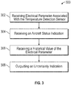
FIG. 3 illustrates a flow diagram of the sequence of operations performed according to one or more embodiment. - A detailed description of one or more embodiments of the disclosed apparatus and method are presented herein by way of exemplification and not limitation with reference to the Figures.
- Temperature detection systems may include various systems and apparatuses for determining environment temperatures. Such systems may include switches, temperature sensors, or other sensory inputs. Ground conduction between sensors and control systems may increase instrument uncertainty. Such uncertainty may be latent in that issues are not determined or remain dormant without diagnosis.
- Referring to
FIG. 1 , anaircraft 100 is shown. Theaircraft 100 includes atemperature sensor 102. Thetemperature sensor 102 may be any type of temperature sensing device. Thetemperature sensor 102 includes aground sheath 104. Theground sheath 104 may be electrically connected toground connections 110. Theground connections 110 may be portions of a body of theaircraft 100. Theground sheath 104 may encase acentral conductor 106. Thecentral conductor 106 may be electrically conductive and attached to acontroller 120. Thetemperature sensor 102 may include acentral return 108. Thecentral return 108 may be conductively connected with theground sheath 104. Thecentral conductor 106 may be conductively connected to thecentral return 108 by a temperature dependentresistive element 112. Those versed in the art will readily appreciate that the temperature dependentresistive element 112 may be a thermistor or other device employing any kind of temperature sensitive components and configurations. - The
temperature sensor 102 is connected tocontroller 120 through thecentral conductor 106 and thecentral return 108,ground sheath 104, theground connections 110, a body of theaircraft 100, or any other source of potential necessary to measure resistance of the temperature dependentresistive element 112. Thecontroller 120 may include any combination of processors, field programmable gate arrays (FPGA), or application specific integrated circuits (ASIC). Thecontroller 120 may include adigital storage device 160, volatile and non-volatile-but entirely non-transitory-operable to store machine instructions and the like as a controller program product in cooperation with theprocessors 162 and other processing mechanisms to receive, calculate, and control devices, as necessary. Theprocessors 162 may be in communication with digital or analog input andoutput channels 164 configured to receive electrical parameters 132 (as shown in as an at least one example inFIG. 2 ) from thecentral conductor 106 and thecentral return 108. Machine instructions may be stored as a controller logic program (e.g., stored instructions, stored machine instructions, stored steps) in any language or representation, including-but not limited to-machine code, assembly instructions, C, C++, C#, PASCAL, COBAL, PYTHON, JAVA, and RUBY. It should be appreciated that any type of wired or wireless configuration is appreciated for any of the communications from thecontroller 120. Wireless protocols such as ZIGBEE, WI-FI, BLUETOOTH, or any other implement may be used. Communications may be realized through any protocol or medium known or unknown. - The
controller 120 may receive an electrical parameter or determine anelectrical parameter 132 from thetemperature sensor 102. Theelectrical parameter 132 may be resistance, voltage, current, capacitance, inductance, or any otherelectrical parameter 132 that characterizes the temperature associated with thetemperature sensor 102. Thecontroller 120 may receive any number of inputs, including anaircraft status indication 124. Theaircraft status indication 124 may be any number or type of information associated with theaircraft 100. - As an example, the
aircraft status indication 124 may be or include ageographical location 126 associated with thetemperature sensor 102. Thegeographical location 126 may be a GPS location or any other designation of location oraircraft 100. Theaircraft status indication 124 may be analtitude 128 associated with ageographical location 126. Theaircraft status indication 124 may beweather 130 associated with ageographical location 126 oraircraft 100. That is, theaircraft status indication 124 may be an environmental or ambient temperature associated with theaircraft 100. Thecontroller 120 may receive theelectrical parameter 132 and theaircraft status indication 124 for comparison with a historical value of theelectrical parameter 132 to output anuncertainty indication 122. Theuncertainty indication 122 may be an indication of a grounded conductor associated with thetemperature sensor 102. - Referring to
FIG. 2 , agraph 200 depicts one of many examples for determining uncertainty of thetemperature sensor 102. Theelectrical parameter 132 may be received by thecontroller 120. Thecontroller 120 may also receive anaircraft status indication 124. Theaircraft status indication 124 may be flight phases. Thecontroller 120 may receive or store expected value ranges 136 associated with each of the flight phases. The expected value ranges 136 may be defined bytrendline 134. Flight phases may be based on any number of factors including attitude, velocity, altitude, or other operational factors. - As one of many possible phases, the flight phases may include an
aircraft descent phase 150. Theaircraft descent phase 150 may be associated with the expectedvalue range 136 having a lowestaverage magnitude 140. That is, acceptable values of theelectrical parameter 132 having an expectedvalue range 136 during theaircraft descent phase 150 may have a lowestaverage magnitude 140 when compared with other flight phases. Thecontroller 120 may receive theaircraft status indication 124 and retrieve the expectedvalue range 136 having the lowestaverage magnitude 140 as a historical value. As one of many possible configurations, thecontroller 120 may compare theaircraft descent phase 150 with the associated expectedvalue range 136 with theelectrical parameter 132 received by the temperature sensing device. In response theelectrical parameter 132 being outside of the expectedvalue range 136, thecontroller 120 may output theuncertainty indication 122. - As one of many possible phases, the flight phases may include an
aircraft cruise phase 152. Theaircraft cruise phase 152 may be associated with the expectedvalue range 136 having a loweraverage magnitude 142. That is, acceptable values of theelectrical parameter 132 having an expectedvalue range 136 during theaircraft cruise phase 152 may have a loweraverage magnitude 142 when compared with other flight phases. Theaircraft cruise phase 152 may have anaverage magnitude 142 that is greater than the lowestaverage magnitude 140. It should also be appreciated that the expectedvalue range 136 associated with theaircraft cruise phase 152 may have a starting value greater than an ending value of the expectedvalue range 136 associated with theaircraft descent phase 150. As another example of many possible values the expectedvalue range 136 associated with theaircraft cruise phase 152 may have a starting value less than the ending value of the expectedvalue range 136 associated with theaircraft descent phase 150 such that the two expected value ranges 136 overlap. In such a case, the loweraverage magnitude 142 associated with theaircraft cruise phase 152 may still be greater than the lowestaverage magnitude 140 associated with theaircraft descent phase 150. - As one of many possible phases, the flight phases may include an aircraft
takeoff roll phase 154. The aircrafttakeoff roll phase 154 may be associated with the expectedvalue range 136 having a greateraverage magnitude 144. That is, acceptable values of theelectrical parameter 132 having an expectedvalue range 136 during the aircrafttakeoff roll phase 154 may have a greateraverage magnitude 144 when compared with other flight phases. The aircrafttakeoff roll phase 154 may have anaverage magnitude 144 that is greater than the lowestaverage magnitude 140 and the loweraverage magnitude 142. It should also be appreciated that the expectedvalue range 136 associated with the aircrafttakeoff roll phase 154 may have a starting value greater than an ending value of the expectedvalue range 136 associated with theaircraft cruise phase 152. As another example of many possible values the expectedvalue range 136 associated with the aircrafttakeoff roll phase 154 may have a starting value less than the ending value of the expectedvalue range 136 associated with theaircraft cruise phase 152 such that the two expected value ranges 136 overlap. In such a case, the greateraverage magnitude 144 associated with aircrafttakeoff roll phase 154 may still be greater than the loweraverage magnitude 142 associated with theaircraft cruise phase 152. - As one of many possible phases, the flight phases may include an aircraft
initial climb phase 156. The aircraftinitial climb phase 156 may be associated with the expectedvalue range 136 having a greatestaverage magnitude 146. That is, acceptable values of theelectrical parameter 132 having an expectedvalue range 136 during the aircraftinitial climb phase 156 may have a greatestaverage magnitude 146 when compared with other flight phases. The aircraftinitial climb phase 156 may have anaverage magnitude 146 that is greater than the lowestaverage magnitude 140, the loweraverage magnitude 142, and the greateraverage magnitude 144. It should also be appreciated that the expectedvalue range 136 associated with the aircraftinitial climb phase 156 may have a starting value greater than an ending value of the expectedvalue range 136 associated with the aircrafttakeoff roll phase 154. As another example of many possible values the expectedvalue range 136 associated with the aircraftinitial climb phase 156 may have a starting value less than the ending value of the expectedvalue range 136 associated with the aircrafttakeoff roll phase 154 such that the two expected value ranges 136 overlap. In such a case, the greatestaverage magnitude 146 associated with aircraftinitial climb phase 156 may still be greater than the greateraverage magnitude 144 associated with the aircrafttakeoff roll phase 154. - Those with skill in the art will readily appreciate that the expected value ranges 136 may overlap or not overlap at varying rates and that any type of statistical network or system may be used to predict expected values of the
electrical parameter 132 and the expected value ranges 136 listed such that they are correlated or associated with theaircraft status indication 124. The specific enumeration of ranges, numerical values, average magnitudes, and the like are merely as example, as those with skill in the art will readily appreciate that any statistical or numerical analysis may be used to compare the givenaircraft status indications 124 withelectrical parameters 132 and historical values. - The
controller 120 may receive theaircraft status indication 124 and retrieve the expectedvalue range 136 having the lowestaverage magnitude 140 as a historical value. As one of many possible configurations, thecontroller 120 may compare theaircraft descent phase 150 with the associated expectedvalue range 136 with theelectrical parameter 132 received by the temperature sensing device. In response theelectrical parameter 132 being outside of the expectedvalue range 136, thecontroller 120 may output theuncertainty indication 122. - Referring to
FIG. 3 , aflow chart 300 of the sequence of operations performed. Theflow chart 300 includes receiving anelectrical parameter 132 associated with atemperature sensor 102 inblock 302. It should be appreciated thatelectrical parameter 132 may be received or determined by thecontroller 120 or another apparatus associated with thecontroller 120. Theelectrical parameter 132 may include any numerical value of theelectrical parameter 132 or an estimated numerical value of theelectrical parameter 132. Inblock 304, anaircraft status indication 124 is received. Theaircraft status indication 124 may be any one or more of information associated with theaircraft 100. Theaircraft status indication 124 may be a combination of aircraft information provided tocontroller 120 or another apparatus. Inblock 306, a historical value of theelectrical parameter 132 is received. The historical value may be an expectedvalue range 136, a function, numerical value, network of values, or statistical analysis of values associated with theaircraft status indication 124 and theelectrical parameter 132. Inblock 308, anuncertainty indication 122 is outputted. Theuncertainty indication 122 may be any type of signal or process that is retained or informs operators of theaircraft 100. Such indications may be used to operate theaircraft 100. - The terminology used herein is for the purpose of describing particular implementations only and is not intended to be limiting of the present disclosure. As used herein, the singular forms "a", "an" and "the" are intended to include the plural forms as well, unless the context clearly indicates otherwise. It will be further understood that the terms "comprises" and/or "comprising," when used in this specification, specify the presence of stated features, integers, steps, operations, elements, and/or components, but do not preclude the presence or addition of one or more other features, integers, steps, operations, element components, and/or groups thereof.
- While the present disclosure has been described with reference to one or more example implementations, it will be understood by those skilled in the art that various changes may be made, and equivalents may be substituted for elements thereof without departing from the scope of the present disclosure. In addition, many modifications may be made to adapt a particular situation or material to the teachings of the present disclosure without departing from the essential scope thereof. Therefore, it is intended that the present disclosure not be limited to the particular implementation disclosed as the best mode contemplated for carrying out this present disclosure, but that the present disclosure will include all implements falling within the scope of the claims.
Claims (14)
- A system for detecting uncertainty in temperature detection systems, comprising:a temperature sensor including a ground sheath and a central conductor surrounded by the ground sheath, the ground sheath and the central conductor being electrically coupled to one another through a temperature dependent resistive element;a controller connected to the temperature sensor and adapted to detect an electrical parameter of the temperature dependent resistive element, the controller operable upon execution to output an uncertainty indication when the electrical parameter of the temperature dependent resistive element is not within an expected value range based on an aircraft status indication, a historical value of the electrical parameter, and the electrical parameter.
- The system of claim 1, wherein the historical value defines the expected value range based on the aircraft status indication.
- The system of claim 1 or 2, wherein the controller is operable upon execution to output the uncertainty indication when the electrical parameter is outside of the expected value range associated with the aircraft status indication.
- A method for detecting uncertainty in temperature detection installations, comprising:receiving an electrical parameter associated with a temperature sensor;receiving an aircraft status indication;receiving a historical value of the electrical parameter associated with the aircraft status indication; andoutputting an uncertainty indication based on the electrical parameter, the aircraft status indication, and the historical value.
- A controller program product for use by a controller in providing uncertainty indication, comprising:a digital storage device;a controller logic program stored on the digital storage device in controller readable form, the controller logic program being operable upon execution by the controller to receive an electrical parameter from a temperature sensor and an aircraft status indication, and operable to output the uncertainty indication based on a historical value of the electrical parameter associated with the aircraft status indication and the electrical parameter.
- The method of claim 4, or the controller program product of claim 5, wherein the historical value is an expected value range based on the aircraft status indication.
- The method or controller program product of claim 6, wherein
the expected value range has a lowest average magnitude when the aircraft status indication is an aircraft descent phase,
the expected value range has a lower average magnitude greater than the lowest average magnitude when the aircraft status indication is an aircraft cruise phase,
the expected value range has a greater average magnitude greater than the lower average magnitude when the aircraft status indication is an aircraft takeoff roll phase,
the expected value range has a greatest average magnitude greater than the when the aircraft status indication is an aircraft initial climb phase. - The method of claim 6 or 7, wherein outputting the uncertainty indication is responsive to the electrical parameter being outside of the expected value range.
- The system of claim 1, 2 or 3, or the method of any one of claims 4 or 6-8, or the controller program product of any one of claims 5-7, wherein the aircraft status indication includes a geographical location of, or associated with, the temperature sensor.
- The system of any one of claims 1-3 or 9, or the method of any one of claims 4 or 6-9, or the controller program product of any one of claims 5-7 or 9, wherein the aircraft status indication includes an altitude associated with a geographical location.
- The system of any one of claims 1-3, 9 or 10, or the method of any one of claims 4 or 6-10, or the controller program product of any one of claims 5-7, 9 or 10, wherein the aircraft status indication includes weather associated with a geographical location.
- The system of any one of claims 1-3 or 9-11, or the method of any one of claims 4 or 6-11, or the controller program product of any one of claims 5-7 or 9-11, wherein the electrical parameter is resistance.
- The controller program product of any one of claims 6, 7 or 9-12, wherein the controller program product is operable to output the uncertainty indication responsive to the electrical parameter being outside of the expected value range.
- The controller program product of any one of claims 6 or 9-13, or the method of any one of claims 6 or 8-12, wherein the expected value range has a lowest average magnitude when the aircraft status indication is an aircraft descent phase, and
the expected value range has a lower average magnitude greater than the lowest average magnitude when the aircraft status indication is an aircraft cruise phase.
Applications Claiming Priority (1)
| Application Number | Priority Date | Filing Date | Title |
|---|---|---|---|
| US16/545,041 US11237067B2 (en) | 2019-08-20 | 2019-08-20 | Uncertainty diagnosis for temperature detection systems |
Publications (2)
| Publication Number | Publication Date |
|---|---|
| EP3783325A1 true EP3783325A1 (en) | 2021-02-24 |
| EP3783325B1 EP3783325B1 (en) | 2024-08-14 |
Family
ID=68762560
Family Applications (1)
| Application Number | Title | Priority Date | Filing Date |
|---|---|---|---|
| EP19212816.3A Active EP3783325B1 (en) | 2019-08-20 | 2019-12-02 | Uncertainty diagnosis for temperature detection systems |
Country Status (3)
| Country | Link |
|---|---|
| US (1) | US11237067B2 (en) |
| EP (1) | EP3783325B1 (en) |
| ES (1) | ES2992828T3 (en) |
Families Citing this family (2)
| Publication number | Priority date | Publication date | Assignee | Title |
|---|---|---|---|---|
| CN118770168B (en) * | 2024-09-12 | 2024-11-15 | 北京北摩高科摩擦材料股份有限公司 | A method for early warning of aircraft brake wheel temperature based on data processing |
| CN120927144B (en) * | 2025-10-14 | 2026-05-26 | 浙江洛克电力科技有限公司 | Methods, devices, electronic equipment and storage media for monitoring temperature of electromagnetic transformers |
Citations (3)
| Publication number | Priority date | Publication date | Assignee | Title |
|---|---|---|---|---|
| US20110102183A1 (en) * | 2008-03-20 | 2011-05-05 | Siemens Aktiengesellschaft | Spatially resolved temperature measurement inside a spatial detection region |
| US20140358455A1 (en) * | 2013-06-04 | 2014-12-04 | Kidde Technologies, Inc. | Systems and methods for overheat detection system event location |
| US20160370236A1 (en) * | 2015-06-22 | 2016-12-22 | Rosemount Aerospace Inc. | Aircraft total air temperature anomaly detection |
Family Cites Families (24)
| Publication number | Priority date | Publication date | Assignee | Title |
|---|---|---|---|---|
| US3826981A (en) * | 1968-05-03 | 1974-07-30 | H Ross | Solid-state high impedance meter system |
| US3775745A (en) * | 1972-02-03 | 1973-11-27 | Mcpherson D | Engine over-temperature warning system |
| JPS48111181U (en) * | 1972-03-27 | 1973-12-20 | ||
| US3832668A (en) * | 1972-03-31 | 1974-08-27 | Westinghouse Electric Corp | Silicon carbide junction thermistor |
| US4477715A (en) * | 1982-07-19 | 1984-10-16 | Technar Incorporated | PTC thermistor controlled electric diesel fuel heater |
| US4591576A (en) * | 1984-10-03 | 1986-05-27 | Union Carbide Corporation | Process for preparing catalytic cracking catalysts |
| US5167153A (en) * | 1986-04-23 | 1992-12-01 | Fluid Components, Inc. | Method of measuring physical phenomena using a distributed RTD |
| US5184605A (en) * | 1991-01-31 | 1993-02-09 | Excel Tech Ltd. | Therapeutic ultrasound generator with radiation dose control |
| US8473176B2 (en) * | 2008-04-07 | 2013-06-25 | John S. Youngquist | Aircraft monitoring equipment |
| US9127597B2 (en) | 2011-09-23 | 2015-09-08 | The Boeing Company | Sensor system |
| US8798817B2 (en) | 2012-01-31 | 2014-08-05 | Gulfstream Aerospace Corporation | Methods and systems for requesting and retrieving aircraft data during flight of an aircraft |
| US9783293B2 (en) * | 2014-05-20 | 2017-10-10 | Verizon Patent And Licensing Inc. | Unmanned aerial vehicle platform |
| US9233763B1 (en) | 2014-08-19 | 2016-01-12 | Gulfstream Aerospace Corporation | Methods and systems for aircraft systems health trend monitoring |
| CN204760671U (en) * | 2015-05-29 | 2015-11-11 | 湖南宏讯光电线缆有限公司 | Power frequency over -current protection supply socket |
| US10319242B2 (en) * | 2016-11-15 | 2019-06-11 | The Boeing Company | Maneuver prediction for surrounding traffic |
| US10281913B2 (en) * | 2017-08-14 | 2019-05-07 | The Boeing Company | Methods and systems for intelligent predictive aircraft takeoff rejection decision making |
| GB2572154A (en) * | 2018-03-19 | 2019-09-25 | Airbus Operations Ltd | Landing gear temperature characteristic |
| US10845263B2 (en) * | 2018-04-17 | 2020-11-24 | Mks Instruments, Inc. | Thermal conductivity gauge |
| US11016117B2 (en) * | 2018-08-31 | 2021-05-25 | Honeywell International Inc. | Air data probe replacement determination system |
| US20200189764A1 (en) * | 2018-10-18 | 2020-06-18 | Chinedum Uzochukwu Esimai | Flight control safety system |
| US11192664B2 (en) * | 2018-12-10 | 2021-12-07 | Hamilton Sundstrand Corporation | Smart application for aircraft performance data collection |
| US11338910B2 (en) * | 2019-07-22 | 2022-05-24 | Kidde Technologies, Inc. | Integrated landing gear fire detection and fatigue monitoring system |
| US10871403B1 (en) * | 2019-09-23 | 2020-12-22 | Kidde Technologies, Inc. | Aircraft temperature sensor |
| US11460351B2 (en) * | 2019-11-21 | 2022-10-04 | Battelle Energy Alliance, Llc | High-temperature, irradiation-resistant thermocouple, coaxial thermocouple, and related methods |
-
2019
- 2019-08-20 US US16/545,041 patent/US11237067B2/en active Active
- 2019-12-02 ES ES19212816T patent/ES2992828T3/en active Active
- 2019-12-02 EP EP19212816.3A patent/EP3783325B1/en active Active
Patent Citations (3)
| Publication number | Priority date | Publication date | Assignee | Title |
|---|---|---|---|---|
| US20110102183A1 (en) * | 2008-03-20 | 2011-05-05 | Siemens Aktiengesellschaft | Spatially resolved temperature measurement inside a spatial detection region |
| US20140358455A1 (en) * | 2013-06-04 | 2014-12-04 | Kidde Technologies, Inc. | Systems and methods for overheat detection system event location |
| US20160370236A1 (en) * | 2015-06-22 | 2016-12-22 | Rosemount Aerospace Inc. | Aircraft total air temperature anomaly detection |
Also Published As
| Publication number | Publication date |
|---|---|
| US20210055169A1 (en) | 2021-02-25 |
| ES2992828T3 (en) | 2024-12-18 |
| US11237067B2 (en) | 2022-02-01 |
| EP3783325B1 (en) | 2024-08-14 |
Similar Documents
| Publication | Publication Date | Title |
|---|---|---|
| JP7023874B2 (en) | Detection method and device, and method and device to improve detection accuracy | |
| EP3783325B1 (en) | Uncertainty diagnosis for temperature detection systems | |
| RU2688564C2 (en) | Systems and methods of detecting failures when determining spatial position based on air signals and aircraft control settings | |
| CN102844643B (en) | Dynamic pickup measurement range selection | |
| EP2018519B1 (en) | Sensor adaptors and methods | |
| CN106330188B (en) | The A/D resolution ratio of dynamic adjustment | |
| CA3059739C (en) | High voltage measurement system and calibration method | |
| CN101680822B (en) | Dynamic reciprocating-bob rheometry | |
| CN107925405A (en) | For triggering the self-adapting signal threshold value of foot-operated detection | |
| US10101862B2 (en) | Method for measuring a capacitance value | |
| JP2007527073A (en) | Field-mounted process equipment with programmable digital / analog interface | |
| US9797933B2 (en) | Method for monitoring the power consumption of an electrical consumer | |
| WO2015142552A1 (en) | Thermistor based measurement system | |
| EP2027443B1 (en) | Temperature sensor adaptors and methods | |
| EP3223089A1 (en) | Environmental sensor and environmental parameter measurement and prediction method | |
| EP3066895B1 (en) | Self-powered current sensing switch with digital setpoint | |
| JP5864748B2 (en) | 2-wire process control loop current diagnostic apparatus and method | |
| US4148220A (en) | Linearization means and method for a thermistor temperature sensing system | |
| CN109729488A (en) | The non-transient computer readable medium recording program performing of apparatus for management of information and logging program | |
| EP1968026A1 (en) | Linear fire-detector alarming system based on data fusion and the method | |
| CN116558711A (en) | Dynamic multistage air data probe prediction health monitoring system | |
| WO2021257307A1 (en) | Rtd degradation detection | |
| US20190006868A1 (en) | Method and apparatus for controlling charging and discharging of capacitor module, and display apparatus | |
| US12013293B2 (en) | Systems and methods for temperature measurements | |
| WO2015047578A1 (en) | Infrared sensor |
Legal Events
| Date | Code | Title | Description |
|---|---|---|---|
| PUAI | Public reference made under article 153(3) epc to a published international application that has entered the european phase |
Free format text: ORIGINAL CODE: 0009012 |
|
| STAA | Information on the status of an ep patent application or granted ep patent |
Free format text: STATUS: THE APPLICATION HAS BEEN PUBLISHED |
|
| AK | Designated contracting states |
Kind code of ref document: A1 Designated state(s): AL AT BE BG CH CY CZ DE DK EE ES FI FR GB GR HR HU IE IS IT LI LT LU LV MC MK MT NL NO PL PT RO RS SE SI SK SM TR |
|
| AX | Request for extension of the european patent |
Extension state: BA ME |
|
| STAA | Information on the status of an ep patent application or granted ep patent |
Free format text: STATUS: REQUEST FOR EXAMINATION WAS MADE |
|
| 17P | Request for examination filed |
Effective date: 20210824 |
|
| RBV | Designated contracting states (corrected) |
Designated state(s): AL AT BE BG CH CY CZ DE DK EE ES FI FR GB GR HR HU IE IS IT LI LT LU LV MC MK MT NL NO PL PT RO RS SE SI SK SM TR |
|
| STAA | Information on the status of an ep patent application or granted ep patent |
Free format text: STATUS: EXAMINATION IS IN PROGRESS |
|
| 17Q | First examination report despatched |
Effective date: 20220928 |
|
| GRAP | Despatch of communication of intention to grant a patent |
Free format text: ORIGINAL CODE: EPIDOSNIGR1 |
|
| STAA | Information on the status of an ep patent application or granted ep patent |
Free format text: STATUS: GRANT OF PATENT IS INTENDED |
|
| INTG | Intention to grant announced |
Effective date: 20240314 |
|
| GRAS | Grant fee paid |
Free format text: ORIGINAL CODE: EPIDOSNIGR3 |
|
| GRAA | (expected) grant |
Free format text: ORIGINAL CODE: 0009210 |
|
| STAA | Information on the status of an ep patent application or granted ep patent |
Free format text: STATUS: THE PATENT HAS BEEN GRANTED |
|
| AK | Designated contracting states |
Kind code of ref document: B1 Designated state(s): AL AT BE BG CH CY CZ DE DK EE ES FI FR GB GR HR HU IE IS IT LI LT LU LV MC MK MT NL NO PL PT RO RS SE SI SK SM TR |
|
| REG | Reference to a national code |
Ref country code: GB Ref legal event code: FG4D |
|
| REG | Reference to a national code |
Ref country code: CH Ref legal event code: EP |
|
| REG | Reference to a national code |
Ref country code: DE Ref legal event code: R096 Ref document number: 602019056923 Country of ref document: DE |
|
| REG | Reference to a national code |
Ref country code: IE Ref legal event code: FG4D |
|
| REG | Reference to a national code |
Ref country code: LT Ref legal event code: MG9D |
|
| REG | Reference to a national code |
Ref country code: NL Ref legal event code: MP Effective date: 20240814 Ref country code: ES Ref legal event code: FG2A Ref document number: 2992828 Country of ref document: ES Kind code of ref document: T3 Effective date: 20241218 |
|
| PG25 | Lapsed in a contracting state [announced via postgrant information from national office to epo] |
Ref country code: NO Free format text: LAPSE BECAUSE OF FAILURE TO SUBMIT A TRANSLATION OF THE DESCRIPTION OR TO PAY THE FEE WITHIN THE PRESCRIBED TIME-LIMIT Effective date: 20241114 |
|
| REG | Reference to a national code |
Ref country code: AT Ref legal event code: MK05 Ref document number: 1713678 Country of ref document: AT Kind code of ref document: T Effective date: 20240814 |
|
| PG25 | Lapsed in a contracting state [announced via postgrant information from national office to epo] |
Ref country code: GR Free format text: LAPSE BECAUSE OF FAILURE TO SUBMIT A TRANSLATION OF THE DESCRIPTION OR TO PAY THE FEE WITHIN THE PRESCRIBED TIME-LIMIT Effective date: 20241115 Ref country code: NL Free format text: LAPSE BECAUSE OF FAILURE TO SUBMIT A TRANSLATION OF THE DESCRIPTION OR TO PAY THE FEE WITHIN THE PRESCRIBED TIME-LIMIT Effective date: 20240814 Ref country code: FI Free format text: LAPSE BECAUSE OF FAILURE TO SUBMIT A TRANSLATION OF THE DESCRIPTION OR TO PAY THE FEE WITHIN THE PRESCRIBED TIME-LIMIT Effective date: 20240814 Ref country code: PL Free format text: LAPSE BECAUSE OF FAILURE TO SUBMIT A TRANSLATION OF THE DESCRIPTION OR TO PAY THE FEE WITHIN THE PRESCRIBED TIME-LIMIT Effective date: 20240814 Ref country code: PT Free format text: LAPSE BECAUSE OF FAILURE TO SUBMIT A TRANSLATION OF THE DESCRIPTION OR TO PAY THE FEE WITHIN THE PRESCRIBED TIME-LIMIT Effective date: 20241216 |
|
| PG25 | Lapsed in a contracting state [announced via postgrant information from national office to epo] |
Ref country code: BG Free format text: LAPSE BECAUSE OF FAILURE TO SUBMIT A TRANSLATION OF THE DESCRIPTION OR TO PAY THE FEE WITHIN THE PRESCRIBED TIME-LIMIT Effective date: 20240814 |
|
| PG25 | Lapsed in a contracting state [announced via postgrant information from national office to epo] |
Ref country code: LV Free format text: LAPSE BECAUSE OF FAILURE TO SUBMIT A TRANSLATION OF THE DESCRIPTION OR TO PAY THE FEE WITHIN THE PRESCRIBED TIME-LIMIT Effective date: 20240814 |
|
| PG25 | Lapsed in a contracting state [announced via postgrant information from national office to epo] |
Ref country code: IS Free format text: LAPSE BECAUSE OF FAILURE TO SUBMIT A TRANSLATION OF THE DESCRIPTION OR TO PAY THE FEE WITHIN THE PRESCRIBED TIME-LIMIT Effective date: 20241214 Ref country code: AT Free format text: LAPSE BECAUSE OF FAILURE TO SUBMIT A TRANSLATION OF THE DESCRIPTION OR TO PAY THE FEE WITHIN THE PRESCRIBED TIME-LIMIT Effective date: 20240814 |
|
| PG25 | Lapsed in a contracting state [announced via postgrant information from national office to epo] |
Ref country code: HR Free format text: LAPSE BECAUSE OF FAILURE TO SUBMIT A TRANSLATION OF THE DESCRIPTION OR TO PAY THE FEE WITHIN THE PRESCRIBED TIME-LIMIT Effective date: 20240814 |
|
| PG25 | Lapsed in a contracting state [announced via postgrant information from national office to epo] |
Ref country code: RS Free format text: LAPSE BECAUSE OF FAILURE TO SUBMIT A TRANSLATION OF THE DESCRIPTION OR TO PAY THE FEE WITHIN THE PRESCRIBED TIME-LIMIT Effective date: 20241114 |
|
| PG25 | Lapsed in a contracting state [announced via postgrant information from national office to epo] |
Ref country code: RS Free format text: LAPSE BECAUSE OF FAILURE TO SUBMIT A TRANSLATION OF THE DESCRIPTION OR TO PAY THE FEE WITHIN THE PRESCRIBED TIME-LIMIT Effective date: 20241114 Ref country code: PT Free format text: LAPSE BECAUSE OF FAILURE TO SUBMIT A TRANSLATION OF THE DESCRIPTION OR TO PAY THE FEE WITHIN THE PRESCRIBED TIME-LIMIT Effective date: 20241216 Ref country code: PL Free format text: LAPSE BECAUSE OF FAILURE TO SUBMIT A TRANSLATION OF THE DESCRIPTION OR TO PAY THE FEE WITHIN THE PRESCRIBED TIME-LIMIT Effective date: 20240814 Ref country code: NO Free format text: LAPSE BECAUSE OF FAILURE TO SUBMIT A TRANSLATION OF THE DESCRIPTION OR TO PAY THE FEE WITHIN THE PRESCRIBED TIME-LIMIT Effective date: 20241114 Ref country code: NL Free format text: LAPSE BECAUSE OF FAILURE TO SUBMIT A TRANSLATION OF THE DESCRIPTION OR TO PAY THE FEE WITHIN THE PRESCRIBED TIME-LIMIT Effective date: 20240814 Ref country code: LV Free format text: LAPSE BECAUSE OF FAILURE TO SUBMIT A TRANSLATION OF THE DESCRIPTION OR TO PAY THE FEE WITHIN THE PRESCRIBED TIME-LIMIT Effective date: 20240814 Ref country code: IS Free format text: LAPSE BECAUSE OF FAILURE TO SUBMIT A TRANSLATION OF THE DESCRIPTION OR TO PAY THE FEE WITHIN THE PRESCRIBED TIME-LIMIT Effective date: 20241214 Ref country code: HR Free format text: LAPSE BECAUSE OF FAILURE TO SUBMIT A TRANSLATION OF THE DESCRIPTION OR TO PAY THE FEE WITHIN THE PRESCRIBED TIME-LIMIT Effective date: 20240814 Ref country code: GR Free format text: LAPSE BECAUSE OF FAILURE TO SUBMIT A TRANSLATION OF THE DESCRIPTION OR TO PAY THE FEE WITHIN THE PRESCRIBED TIME-LIMIT Effective date: 20241115 Ref country code: FI Free format text: LAPSE BECAUSE OF FAILURE TO SUBMIT A TRANSLATION OF THE DESCRIPTION OR TO PAY THE FEE WITHIN THE PRESCRIBED TIME-LIMIT Effective date: 20240814 Ref country code: BG Free format text: LAPSE BECAUSE OF FAILURE TO SUBMIT A TRANSLATION OF THE DESCRIPTION OR TO PAY THE FEE WITHIN THE PRESCRIBED TIME-LIMIT Effective date: 20240814 Ref country code: AT Free format text: LAPSE BECAUSE OF FAILURE TO SUBMIT A TRANSLATION OF THE DESCRIPTION OR TO PAY THE FEE WITHIN THE PRESCRIBED TIME-LIMIT Effective date: 20240814 |
|
| PG25 | Lapsed in a contracting state [announced via postgrant information from national office to epo] |
Ref country code: SM Free format text: LAPSE BECAUSE OF FAILURE TO SUBMIT A TRANSLATION OF THE DESCRIPTION OR TO PAY THE FEE WITHIN THE PRESCRIBED TIME-LIMIT Effective date: 20240814 Ref country code: RO Free format text: LAPSE BECAUSE OF FAILURE TO SUBMIT A TRANSLATION OF THE DESCRIPTION OR TO PAY THE FEE WITHIN THE PRESCRIBED TIME-LIMIT Effective date: 20240814 Ref country code: DK Free format text: LAPSE BECAUSE OF FAILURE TO SUBMIT A TRANSLATION OF THE DESCRIPTION OR TO PAY THE FEE WITHIN THE PRESCRIBED TIME-LIMIT Effective date: 20240814 |
|
| PG25 | Lapsed in a contracting state [announced via postgrant information from national office to epo] |
Ref country code: EE Free format text: LAPSE BECAUSE OF FAILURE TO SUBMIT A TRANSLATION OF THE DESCRIPTION OR TO PAY THE FEE WITHIN THE PRESCRIBED TIME-LIMIT Effective date: 20240814 |
|
| PG25 | Lapsed in a contracting state [announced via postgrant information from national office to epo] |
Ref country code: CZ Free format text: LAPSE BECAUSE OF FAILURE TO SUBMIT A TRANSLATION OF THE DESCRIPTION OR TO PAY THE FEE WITHIN THE PRESCRIBED TIME-LIMIT Effective date: 20240814 |
|
| PG25 | Lapsed in a contracting state [announced via postgrant information from national office to epo] |
Ref country code: SK Free format text: LAPSE BECAUSE OF FAILURE TO SUBMIT A TRANSLATION OF THE DESCRIPTION OR TO PAY THE FEE WITHIN THE PRESCRIBED TIME-LIMIT Effective date: 20240814 Ref country code: IT Free format text: LAPSE BECAUSE OF FAILURE TO SUBMIT A TRANSLATION OF THE DESCRIPTION OR TO PAY THE FEE WITHIN THE PRESCRIBED TIME-LIMIT Effective date: 20240814 |
|
| REG | Reference to a national code |
Ref country code: DE Ref legal event code: R097 Ref document number: 602019056923 Country of ref document: DE |
|
| PLBE | No opposition filed within time limit |
Free format text: ORIGINAL CODE: 0009261 |
|
| STAA | Information on the status of an ep patent application or granted ep patent |
Free format text: STATUS: NO OPPOSITION FILED WITHIN TIME LIMIT |
|
| PG25 | Lapsed in a contracting state [announced via postgrant information from national office to epo] |
Ref country code: MC Free format text: LAPSE BECAUSE OF FAILURE TO SUBMIT A TRANSLATION OF THE DESCRIPTION OR TO PAY THE FEE WITHIN THE PRESCRIBED TIME-LIMIT Effective date: 20240814 |
|
| 26N | No opposition filed |
Effective date: 20250515 |
|
| REG | Reference to a national code |
Ref country code: CH Ref legal event code: PL |
|
| PG25 | Lapsed in a contracting state [announced via postgrant information from national office to epo] |
Ref country code: LU Free format text: LAPSE BECAUSE OF NON-PAYMENT OF DUE FEES Effective date: 20241202 |
|
| PG25 | Lapsed in a contracting state [announced via postgrant information from national office to epo] |
Ref country code: SE Free format text: LAPSE BECAUSE OF FAILURE TO SUBMIT A TRANSLATION OF THE DESCRIPTION OR TO PAY THE FEE WITHIN THE PRESCRIBED TIME-LIMIT Effective date: 20240814 |
|
| REG | Reference to a national code |
Ref country code: BE Ref legal event code: MM Effective date: 20241231 |
|
| PG25 | Lapsed in a contracting state [announced via postgrant information from national office to epo] |
Ref country code: BE Free format text: LAPSE BECAUSE OF NON-PAYMENT OF DUE FEES Effective date: 20241231 |
|
| PG25 | Lapsed in a contracting state [announced via postgrant information from national office to epo] |
Ref country code: CH Free format text: LAPSE BECAUSE OF NON-PAYMENT OF DUE FEES Effective date: 20241231 |
|
| PG25 | Lapsed in a contracting state [announced via postgrant information from national office to epo] |
Ref country code: IE Free format text: LAPSE BECAUSE OF NON-PAYMENT OF DUE FEES Effective date: 20241202 |
|
| PGFP | Annual fee paid to national office [announced via postgrant information from national office to epo] |
Ref country code: DE Payment date: 20251126 Year of fee payment: 7 |
|
| PGFP | Annual fee paid to national office [announced via postgrant information from national office to epo] |
Ref country code: GB Payment date: 20251119 Year of fee payment: 7 |
|
| PGFP | Annual fee paid to national office [announced via postgrant information from national office to epo] |
Ref country code: FR Payment date: 20251120 Year of fee payment: 7 |
|
| PG25 | Lapsed in a contracting state [announced via postgrant information from national office to epo] |
Ref country code: CY Free format text: LAPSE BECAUSE OF FAILURE TO SUBMIT A TRANSLATION OF THE DESCRIPTION OR TO PAY THE FEE WITHIN THE PRESCRIBED TIME-LIMIT; INVALID AB INITIO Effective date: 20191202 |
|
| PGFP | Annual fee paid to national office [announced via postgrant information from national office to epo] |
Ref country code: ES Payment date: 20260102 Year of fee payment: 7 |
|
| PG25 | Lapsed in a contracting state [announced via postgrant information from national office to epo] |
Ref country code: TR Free format text: LAPSE BECAUSE OF FAILURE TO SUBMIT A TRANSLATION OF THE DESCRIPTION OR TO PAY THE FEE WITHIN THE PRESCRIBED TIME-LIMIT Effective date: 20240814 |
|
| PG25 | Lapsed in a contracting state [announced via postgrant information from national office to epo] |
Ref country code: HU Free format text: LAPSE BECAUSE OF FAILURE TO SUBMIT A TRANSLATION OF THE DESCRIPTION OR TO PAY THE FEE WITHIN THE PRESCRIBED TIME-LIMIT; INVALID AB INITIO Effective date: 20191202 |
|
| PG25 | Lapsed in a contracting state [announced via postgrant information from national office to epo] |
Ref country code: SI Free format text: LAPSE BECAUSE OF FAILURE TO SUBMIT A TRANSLATION OF THE DESCRIPTION OR TO PAY THE FEE WITHIN THE PRESCRIBED TIME-LIMIT Effective date: 20240814 |
|
| PG25 | Lapsed in a contracting state [announced via postgrant information from national office to epo] |
Ref country code: LT Free format text: LAPSE BECAUSE OF FAILURE TO SUBMIT A TRANSLATION OF THE DESCRIPTION OR TO PAY THE FEE WITHIN THE PRESCRIBED TIME-LIMIT Effective date: 20240814 |