EP3783202A1 - Observation device, observation method, and program - Google Patents
Observation device, observation method, and program Download PDFInfo
- Publication number
- EP3783202A1 EP3783202A1 EP19788439.8A EP19788439A EP3783202A1 EP 3783202 A1 EP3783202 A1 EP 3783202A1 EP 19788439 A EP19788439 A EP 19788439A EP 3783202 A1 EP3783202 A1 EP 3783202A1
- Authority
- EP
- European Patent Office
- Prior art keywords
- turbo
- machine
- unstable operation
- unit
- detecting
- Prior art date
- Legal status (The legal status is an assumption and is not a legal conclusion. Google has not performed a legal analysis and makes no representation as to the accuracy of the status listed.)
- Pending
Links
Images







Classifications
-
- F—MECHANICAL ENGINEERING; LIGHTING; HEATING; WEAPONS; BLASTING
- F23—COMBUSTION APPARATUS; COMBUSTION PROCESSES
- F23R—GENERATING COMBUSTION PRODUCTS OF HIGH PRESSURE OR HIGH VELOCITY, e.g. GAS-TURBINE COMBUSTION CHAMBERS
- F23R3/00—Continuous combustion chambers using liquid or gaseous fuel
- F23R3/28—Continuous combustion chambers using liquid or gaseous fuel characterised by the fuel supply
-
- F—MECHANICAL ENGINEERING; LIGHTING; HEATING; WEAPONS; BLASTING
- F02—COMBUSTION ENGINES; HOT-GAS OR COMBUSTION-PRODUCT ENGINE PLANTS
- F02C—GAS-TURBINE PLANTS; AIR INTAKES FOR JET-PROPULSION PLANTS; CONTROLLING FUEL SUPPLY IN AIR-BREATHING JET-PROPULSION PLANTS
- F02C9/00—Controlling gas-turbine plants; Controlling fuel supply in air- breathing jet-propulsion plants
- F02C9/26—Control of fuel supply
- F02C9/28—Regulating systems responsive to plant or ambient parameters, e.g. temperature, pressure, rotor speed
-
- F—MECHANICAL ENGINEERING; LIGHTING; HEATING; WEAPONS; BLASTING
- F01—MACHINES OR ENGINES IN GENERAL; ENGINE PLANTS IN GENERAL; STEAM ENGINES
- F01D—NON-POSITIVE DISPLACEMENT MACHINES OR ENGINES, e.g. STEAM TURBINES
- F01D21/00—Shutting-down of machines or engines, e.g. in emergency; Regulating, controlling, or safety means not otherwise provided for
- F01D21/003—Arrangements for testing or measuring
-
- F—MECHANICAL ENGINEERING; LIGHTING; HEATING; WEAPONS; BLASTING
- F01—MACHINES OR ENGINES IN GENERAL; ENGINE PLANTS IN GENERAL; STEAM ENGINES
- F01D—NON-POSITIVE DISPLACEMENT MACHINES OR ENGINES, e.g. STEAM TURBINES
- F01D21/00—Shutting-down of machines or engines, e.g. in emergency; Regulating, controlling, or safety means not otherwise provided for
- F01D21/14—Shutting-down of machines or engines, e.g. in emergency; Regulating, controlling, or safety means not otherwise provided for responsive to other specific conditions
-
- F—MECHANICAL ENGINEERING; LIGHTING; HEATING; WEAPONS; BLASTING
- F01—MACHINES OR ENGINES IN GENERAL; ENGINE PLANTS IN GENERAL; STEAM ENGINES
- F01D—NON-POSITIVE DISPLACEMENT MACHINES OR ENGINES, e.g. STEAM TURBINES
- F01D25/00—Component parts, details, or accessories, not provided for in, or of interest apart from, other groups
-
- F—MECHANICAL ENGINEERING; LIGHTING; HEATING; WEAPONS; BLASTING
- F01—MACHINES OR ENGINES IN GENERAL; ENGINE PLANTS IN GENERAL; STEAM ENGINES
- F01D—NON-POSITIVE DISPLACEMENT MACHINES OR ENGINES, e.g. STEAM TURBINES
- F01D25/00—Component parts, details, or accessories, not provided for in, or of interest apart from, other groups
- F01D25/04—Antivibration arrangements
-
- F—MECHANICAL ENGINEERING; LIGHTING; HEATING; WEAPONS; BLASTING
- F02—COMBUSTION ENGINES; HOT-GAS OR COMBUSTION-PRODUCT ENGINE PLANTS
- F02C—GAS-TURBINE PLANTS; AIR INTAKES FOR JET-PROPULSION PLANTS; CONTROLLING FUEL SUPPLY IN AIR-BREATHING JET-PROPULSION PLANTS
- F02C7/00—Features, components parts, details or accessories, not provided for in, or of interest apart form groups F02C1/00 - F02C6/00; Air intakes for jet-propulsion plants
- F02C7/32—Arrangement, mounting, or driving, of auxiliaries
-
- F—MECHANICAL ENGINEERING; LIGHTING; HEATING; WEAPONS; BLASTING
- F02—COMBUSTION ENGINES; HOT-GAS OR COMBUSTION-PRODUCT ENGINE PLANTS
- F02C—GAS-TURBINE PLANTS; AIR INTAKES FOR JET-PROPULSION PLANTS; CONTROLLING FUEL SUPPLY IN AIR-BREATHING JET-PROPULSION PLANTS
- F02C9/00—Controlling gas-turbine plants; Controlling fuel supply in air- breathing jet-propulsion plants
-
- F—MECHANICAL ENGINEERING; LIGHTING; HEATING; WEAPONS; BLASTING
- F02—COMBUSTION ENGINES; HOT-GAS OR COMBUSTION-PRODUCT ENGINE PLANTS
- F02C—GAS-TURBINE PLANTS; AIR INTAKES FOR JET-PROPULSION PLANTS; CONTROLLING FUEL SUPPLY IN AIR-BREATHING JET-PROPULSION PLANTS
- F02C9/00—Controlling gas-turbine plants; Controlling fuel supply in air- breathing jet-propulsion plants
- F02C9/16—Control of working fluid flow
-
- F—MECHANICAL ENGINEERING; LIGHTING; HEATING; WEAPONS; BLASTING
- F04—POSITIVE - DISPLACEMENT MACHINES FOR LIQUIDS; PUMPS FOR LIQUIDS OR ELASTIC FLUIDS
- F04D—NON-POSITIVE-DISPLACEMENT PUMPS
- F04D27/00—Control, e.g. regulation, of pumps, pumping installations or pumping systems specially adapted for elastic fluids
- F04D27/001—Testing thereof; Determination or simulation of flow characteristics; Stall or surge detection, e.g. condition monitoring
-
- F—MECHANICAL ENGINEERING; LIGHTING; HEATING; WEAPONS; BLASTING
- F04—POSITIVE - DISPLACEMENT MACHINES FOR LIQUIDS; PUMPS FOR LIQUIDS OR ELASTIC FLUIDS
- F04D—NON-POSITIVE-DISPLACEMENT PUMPS
- F04D29/00—Details, component parts, or accessories
- F04D29/66—Combating cavitation, whirls, noise, vibration or the like; Balancing
- F04D29/661—Combating cavitation, whirls, noise, vibration or the like; Balancing especially adapted for elastic fluid pumps
- F04D29/668—Combating cavitation, whirls, noise, vibration or the like; Balancing especially adapted for elastic fluid pumps damping or preventing mechanical vibrations
-
- F—MECHANICAL ENGINEERING; LIGHTING; HEATING; WEAPONS; BLASTING
- F23—COMBUSTION APPARATUS; COMBUSTION PROCESSES
- F23R—GENERATING COMBUSTION PRODUCTS OF HIGH PRESSURE OR HIGH VELOCITY, e.g. GAS-TURBINE COMBUSTION CHAMBERS
- F23R3/00—Continuous combustion chambers using liquid or gaseous fuel
-
- G—PHYSICS
- G06—COMPUTING OR CALCULATING; COUNTING
- G06F—ELECTRIC DIGITAL DATA PROCESSING
- G06F17/00—Digital computing or data processing equipment or methods, specially adapted for specific functions
- G06F17/10—Complex mathematical operations
- G06F17/11—Complex mathematical operations for solving equations, e.g. nonlinear equations, general mathematical optimization problems
-
- F—MECHANICAL ENGINEERING; LIGHTING; HEATING; WEAPONS; BLASTING
- F05—INDEXING SCHEMES RELATING TO ENGINES OR PUMPS IN VARIOUS SUBCLASSES OF CLASSES F01-F04
- F05D—INDEXING SCHEME FOR ASPECTS RELATING TO NON-POSITIVE-DISPLACEMENT MACHINES OR ENGINES, GAS-TURBINES OR JET-PROPULSION PLANTS
- F05D2260/00—Function
- F05D2260/80—Diagnostics
-
- F—MECHANICAL ENGINEERING; LIGHTING; HEATING; WEAPONS; BLASTING
- F05—INDEXING SCHEMES RELATING TO ENGINES OR PUMPS IN VARIOUS SUBCLASSES OF CLASSES F01-F04
- F05D—INDEXING SCHEME FOR ASPECTS RELATING TO NON-POSITIVE-DISPLACEMENT MACHINES OR ENGINES, GAS-TURBINES OR JET-PROPULSION PLANTS
- F05D2270/00—Control
- F05D2270/01—Purpose of the control system
- F05D2270/09—Purpose of the control system to cope with emergencies
-
- F—MECHANICAL ENGINEERING; LIGHTING; HEATING; WEAPONS; BLASTING
- F05—INDEXING SCHEMES RELATING TO ENGINES OR PUMPS IN VARIOUS SUBCLASSES OF CLASSES F01-F04
- F05D—INDEXING SCHEME FOR ASPECTS RELATING TO NON-POSITIVE-DISPLACEMENT MACHINES OR ENGINES, GAS-TURBINES OR JET-PROPULSION PLANTS
- F05D2270/00—Control
- F05D2270/30—Control parameters, e.g. input parameters
- F05D2270/334—Vibration measurements
-
- F—MECHANICAL ENGINEERING; LIGHTING; HEATING; WEAPONS; BLASTING
- F05—INDEXING SCHEMES RELATING TO ENGINES OR PUMPS IN VARIOUS SUBCLASSES OF CLASSES F01-F04
- F05D—INDEXING SCHEME FOR ASPECTS RELATING TO NON-POSITIVE-DISPLACEMENT MACHINES OR ENGINES, GAS-TURBINES OR JET-PROPULSION PLANTS
- F05D2270/00—Control
- F05D2270/80—Devices generating input signals, e.g. transducers, sensors, cameras or strain gauges
- F05D2270/808—Strain gauges; Load cells
-
- F—MECHANICAL ENGINEERING; LIGHTING; HEATING; WEAPONS; BLASTING
- F23—COMBUSTION APPARATUS; COMBUSTION PROCESSES
- F23R—GENERATING COMBUSTION PRODUCTS OF HIGH PRESSURE OR HIGH VELOCITY, e.g. GAS-TURBINE COMBUSTION CHAMBERS
- F23R2900/00—Special features of, or arrangements for continuous combustion chambers; Combustion processes therefor
- F23R2900/00013—Reducing thermo-acoustic vibrations by active means
Definitions
- the present invention relates to an observation apparatus, an observation method, and a program that can be applied to various technical fields of gas turbine engines for aircraft, watercraft, or automobiles, gas turbines for power generation, steam turbines, and the like.
- Turbo-machines that constitute engines for aircraft and gas turbines function to compress or expand a working fluid (working air).
- working fluid working air
- a configuration in which a number of blades are disposed on a circumference with rotating blades and stationary blades alternately combined is employed, and compression or expansion can be achieved by allowing the working fluid to pass through an annular flow channel between those blades.
- the above-mentioned risk is avoided by a method of performing the operation only under stable operation conditions on a design operation line set such that unstable operations are unlikely to occur and performing control to avoid the occurrence of the unstable operations.
- a method of enhancing the safety is employed by setting the blade thickness, the blade width, and the like to be larger than those of the optimum shape or by making a safe design in which the compression performance and the expansion performance are slightly lower in order to avoid damage caused by unstable operations.
- Patent Literature 1 to 8 Basic research to attempt observation and control with similar parameters has also been conducted on unstable operations of a centrifugal compressor.
- Patent Document 1 has disclosed a technology for controlling a combustion state by detecting pressure fluctuations in a combustion chamber of a gas turbine model combustor through a pressure transducer and outputting it as a pressure fluctuation signal, converting the waveform of the output pressure fluctuation signal into a trace in a phase space, calculating a translation error on the basis of the trace, estimating the occurrence of blow-off by comparing the translation error with a threshold, setting a target value of a secondary fuel flow rate, and controlling the secondary fuel flow rate to become closer to the set target value.
- Patent Literature 2 has disclosed an observation apparatus including a detection unit that detects a physical quantity of a physical phenomenon that changes over time, a generation unit that sets the detected physical quantity at each time as a node and generates a complex network in which a plurality of nodes are connected with edges according to a certain condition over time, a calculation unit that determines a predetermined feature amount (average order) in the complex network, and an estimation unit that estimates a state of the physical phenomenon on the basis of the feature amount.
- an object of the present invention to provide an observation apparatus, an observation method, and a program, by which the sign or occurrence of an unstable operation of a turbo-machine can be observed.
- an observation apparatus includes: a detection unit including one or two or more sensors that are disposed in a turbo-machine, are highly time responsive, and observe unsteady fluctuations of the turbo-machine; a computation unit that output signals from the one or two or more sensors every moment, stores time series data for a predetermined period, and calculates in real time a parameter for detecting an unstable operation of the turbo-machine; and a determination unit that compares the parameter for detecting the unstable operation with a predetermined threshold and outputs in real time a determination result of a sign or occurrence of the unstable operation.
- the parameter for detecting the unstable operation typically, a detection parameter applying an observation method based on the complex systems science with respect to the time series data obtained from the output signals from the one or two or more sensors that are disposed in the turbo-machine, are highly time responsive, and observe unsteady fluctuations of the turbo-machine and to determine a sign indicating that the unstable operation (flutter, surge, stall) will occur or a change immediately after the unstable operation (flutter, surge, stall) occurs.
- the observation apparatus favorably further includes a control unit that outputs, when the determination unit outputs the determination result of the sign or occurrence of the unstable operation, a signal for changing an operation condition for an operation control apparatus of the turbo-machine and/or a signal for warning of an operation of the turbo-machine.
- a method of calculating the above-mentioned detection parameter it is effective to use a method of calculating the detection parameter by using an index of a sample entropy, a sample entropy considering a multi-scale property, recurrence plots, or a permutation entropy
- the one or two or more sensors may be disposed on a rotating unit, a stationary unit, an inside of a flow channel, or a wall surface in contact with the flow channel in the turbo-machine.
- the detection unit, the computation unit, and the determination unit may include two or more detection units, two or more computation units, and two or more determination units or the detection unit, the computation unit, and the determination unit may include two or more types of detection units, two or more types of computation units, and two or more types of determination units.
- An observation method includes: disposing one or two or more sensors that are highly time responsive to a turbo-machine and observe unsteady fluctuations of the turbo-machine; inputting output signals from the one or two or more sensors every moment, storing time series data for a predetermined period, and calculating in real time a parameter for detecting an unstable operation of the turbo-machine; and comparing the parameter for detecting the unstable operation with a predetermined threshold and outputting in real time a determination result of a sign or occurrence of the unstable operation.
- flutter which is one of the unstable operations, is a phenomenon in which while the blade vibrations remain at a minute amplitude or immediately damp in normal operation, the amplitude rapidly increases by coupling of the natural frequency of the blade itself and the external force received from the fluid, resulting in damage when the strength limit of the blade is exceeded.
- blades rotating blades, stationary blades
- flutter it is characterized in that blades (rotating blades, stationary blades) arranged in an annular shape in the turbo-machine vibrate at their natural frequencies and have a substantially constant phase difference (including 0 degrees) from the adjacent blades and are amplified while the phase of the blade vibrations is transmitted in the circumferential direction.
- flutter can be prevented if structural damping or the like due to blade mounting parts or the like can be sufficiently increased.
- a limit cycle in which the amplification stops at a constant amplitude is reached in some cases, the safety problem is not solved because there is a danger of fatigue fracture of the blades due to vibrations for a long time. Flutter is likely to occur near the stable operation limit on a lower flow rate side (higher load side) in the compressor and is likely to occur near the stable operation limit on a higher flow rate side (higher flow rate side) in the turbine.
- Stall is a state in which the working fluid passing between the rotating blades and the stationary blades cannot be normally compressed or expanded. Typically, the flow of the boundary layer along the blade surface is separated, resulting in a large energy loss, which prevents compression and expansion as designed. It is a phenomenon of an aerodynamic unstable operation not necessarily accompanied by blade vibrations. Stall is more likely to occur during the compression process of the compressor and is more likely to occur near the stable operation limit on the lower flow rate side (higher load side). The state of the flow around the blade is not the same (or not in the above-mentioned phase) for all the blades in the circumferential direction and its characteristics fluctuate periodically with a phase difference between it and the adjacent blade.
- phase of the fluctuations of the flow is transmitted in the circumferential direction and is transmitted in the direction of rotation of the rotating blades at a speed lower than the rotation speed.
- the fluctuations amplitude of the flow increases in the initial stage of the occurrence of stall, but it usually reaches a limit cycle when it reaches a certain amplitude.
- Surge is characterized in that the entire flow field passing through the turbo-machine begins to fluctuate greatly in the axial direction, leading to large fluctuations in the flow rate itself of the turbo-machine. Moreover, it is also characterized in that its fluctuation frequency is lower (slower) in comparison with the frequency of flutter or stall. It has been reported that in case of the occurrence of surge, flutter of the blades or stall of the flow also occurs at the same time or before it, but the flutter or stall does not always occur with surge and it is not clarified under what conditions the flutter or stall will occur with surge.
- the unstable operation phenomenon occurs in the turbo-machine, it is accompanied by large blade vibrations or flow fluctuations, but the fluctuations have certain periodicity in either case and there is a characteristic that in flutter and stall, the phase returns to the original state after a certain time while the phase propagates in the circumferential direction.
- Blade vibrations and flow fluctuations in normal operation have very small amplitude, those are random fluctuations, and certain periodicity or recurrence is not observed. Therefore, it is possible to immediately determine the sign or occurrence of the unstable operation by computing an index clearly indicating whether the time series data obtained from the high-response fluctuation sensor is random or regular.
- a sign indicating that an unstable operation will occur or a change after the unstable operation occurs can be determined in real time by observing sensor signals, it is possible to avoid the unstable operation immediately after detecting the sign or to safely stop the operation before reaching a serious situation after detecting the occurrence.
- the present invention can be widely usable not only in new products but also in the existing products.
- Fig. 1 is a block diagram showing an observation apparatus according to the embodiment of the present invention.
- an observation apparatus 1 includes a detection unit 10, a computation unit 20, a determination unit 30, and a control unit 40.
- the detection unit 10 includes one or two or more sensors that are disposed in a turbo-machine 2, are highly time responsive, and observe unsteady fluctuations of the turbo-machine 2.
- the detection unit 10 includes a sensor 11 attached to a blade 2a which is the rotating unit of the turbo-machine 2, a sensor 12 attached to a wall surface 2b which is the stationary unit facing a leading end of the blade 2a, and the like.
- a sensor that is the detection unit 10 may be disposed in a flow channel or on a wall surface in contact with the flow channel.
- the sensor 11 is constituted of, for example, a strain gauge that detects strain of the blade in real time and the sensor 12 is constituted of, for example, an unsteady pressure sensor that detects the pressure of the fluid in real time.
- these sensors 11 and 12 are for observing flutter, which is one of the unstable operations.
- the sensor 12 may be disposed in a flow channel or on a wall surface in contact with the flow channel, for example. In order to observe stall and surge, which are unstable operations, it is sufficient to dispose sensors in a similar manner.
- the calculation unit 20 inputs output signals from the sensor 11 and the sensor 12 every moment, stores time series data for a predetermined period, and quantitatively evaluates randomness and a recurrence change on the basis of the time series data, to thereby calculate a parameter for detecting an unstable operation of the turbo-machine 2 in real time.
- the computation unit 20 inputs an output signal from the sensor 11 every moment, stores time series data for a predetermined period, and calculates a parameter for detecting flutter in real time.
- the determination unit 30 compares the parameter for detecting the unstable operation with a predetermined threshold and outputs a determination result of the sign or occurrence of the unstable operation in real time.
- the control unit 40 When the determination unit 30 outputs the determination result of the sign or occurrence of the unstable operation, the control unit 40 outputs a signal for changing the operation condition to an operation control apparatus 3 of the turbo-machine 2. Moreover, when the determination unit 30 outputs the determination result of the sign or occurrence of the unstable operation, the control unit 40 outputs a signal for warning a reporting unit 4 of an operation of the turbo-machine 2.
- the operation control apparatus 3 When the operation control apparatus 3 receives the signal for changing the operation condition, the operation control apparatus 3 controls the turbo-machine 2 to stop the operation of the turbo-machine 2, for example.
- the reporting unit 4 When the reporting unit 4 receives the signal associated with the warning, the reporting unit 4 supplies an alarm signal for a pilot or operator to perform manual control for an aircraft, for example.
- a method of calculating the detection parameter in the computation unit 20 it is effective to use a method of calculating the detection parameter by using an index of a sample entropy, a sample entropy considering a multi-scale property, recurrence plots, or a permutation entropy.
- the method of calculating the detection parameter by using these indices will be described.
- the sample entropy refers to an index for quantitatively evaluating the randomness of the time series data.
- a sample entropy SE is as follows.
- the sample entropy considering the multi-scale property refers to an index for performing coarse graining on the time series data and using the sample entropy.
- the time average of the time series data x(ti) is determined by nonoverlapping average as follows and new time series data y(tj) as shown in Fig. 6 is obtained.
- the recurrence plots refer to an index for visualizing the correlation between the respective points in the phase space. For example, first of all, the time series of pressure fluctuations shown in Fig. 8 is embedded in the phase space as shown in Fig. 9 . Next, the correlation between the respective points in the phase space shown in Fig. 10 is plotted as shown in Fig. 11 by performing computation according to the following equation.
- X t i x t i , x t i + ⁇ , ... x t i + D ⁇ 1 ⁇
- an index DET representing determinism is calculated in accordance with the following equation.
- Stc0, Stc1, and Stc2 are channel names of a strain gauge that detects the strain of the blade 2a in real time.
- the permutation entropy refers to an index for quantitatively evaluating the randomness of the time series data.
- the time series data shown in Fig. 17 is classified into predetermined permutation patterns as shown in Fig. 18 and existence probability p of each of permutation patterns is obtained as shown in Fig. 19 .
- the permutation entropy is calculated by applying p to the Shannon's information entropy.
- the Shannon's information entropy is expressed by the following equation using a discrete probability distribution p of the random variable of the event.
- N D!.
- a permutation entropy hp means more random as it is closer to 1 and means more periodic as it is closer to 0.
- Stc0 to Stc8 are respectively the channel names of the strain gauges that detect the strains of the blade 2a in real time. From E and F in Fig. 20 , the permutation entropy decreases because the periodicity of the waveform increases as q increases. It can be seen that the occurrence of flutter can be captured by detecting it.
- Fig. 21 shows a change over time in the permutation entropy.
- an observation apparatus 100 may include two or more detection units 10, two or more computation units 20, and two or more determination units 30.
- an observation apparatus 100 may include two or more detection units 10, two or more computation units 20, and two or more determination units 30.
- the observation apparatus 100 may include two or more types of detection units 10a to 10d, two or more types of computation units 20a to 20d, and two or more types of determination units 30a to 30d. Accordingly, it is possible to detect more kinds of unstable operations at the same time and enhance the reliability.
- the kind of unstable operations that will occur can be determined by using two or more types of sensors, two or more types of computation units, and two or more types of determination units and mounting them at suitable circumferential or axial positions in the turbo-machine.
- the computation unit(s), the determination unit(s), and the control unit(s) according to the present invention is executable by a computer.
- Those computation unit(s), determination unit(s), and control unit(s) may be considered as programs executable by a computer.
- the present invention can be applied to gas turbine engines for aircraft or watercraft for enhancing the safety during the operation. Moreover, the present invention can be applied to gas turbines for power generation, steam turbines, or wind turbines for power generation for monitoring the operation stability during the operation and enhancing the reliability of the electric power supply.
Landscapes
- Engineering & Computer Science (AREA)
- General Engineering & Computer Science (AREA)
- Mechanical Engineering (AREA)
- Chemical & Material Sciences (AREA)
- Combustion & Propulsion (AREA)
- Physics & Mathematics (AREA)
- Mathematical Physics (AREA)
- General Physics & Mathematics (AREA)
- Data Mining & Analysis (AREA)
- Mathematical Analysis (AREA)
- Mathematical Optimization (AREA)
- Computational Mathematics (AREA)
- Theoretical Computer Science (AREA)
- Pure & Applied Mathematics (AREA)
- Algebra (AREA)
- Databases & Information Systems (AREA)
- Software Systems (AREA)
- Operations Research (AREA)
- Fluid Mechanics (AREA)
- Testing Of Devices, Machine Parts, Or Other Structures Thereof (AREA)
- Control Of Positive-Displacement Air Blowers (AREA)
Abstract
Description
- The present invention relates to an observation apparatus, an observation method, and a program that can be applied to various technical fields of gas turbine engines for aircraft, watercraft, or automobiles, gas turbines for power generation, steam turbines, and the like.
- Turbo-machines (fans, compressors, turbines) that constitute engines for aircraft and gas turbines function to compress or expand a working fluid (working air). Typically, a configuration in which a number of blades are disposed on a circumference with rotating blades and stationary blades alternately combined is employed, and compression or expansion can be achieved by allowing the working fluid to pass through an annular flow channel between those blades.
- It is long known that aerodynamic unstable operations (surge, stall) and unstable operations (flutter) due to fluid structure coupling occur in a turbo-machine. When such an unstable operation occurs, it may lead to a serious accident such as large vibrations of the engine centered on the turbo-machine and damage of parts including the rotating blades and even engine fire due to backflow from a combustor (also during flight of aircraft).
- Such an unstable operation often occurs suddenly during the operation of the turbo-machine, and the operator must recognize it only after it occurs and take measures such as an emergency stop of the engine (also during flight of aircraft).
- In general, during the operation of the turbo-machine, the above-mentioned risk is avoided by a method of performing the operation only under stable operation conditions on a design operation line set such that unstable operations are unlikely to occur and performing control to avoid the occurrence of the unstable operations.
- In the design stage, a method of enhancing the safety is employed by setting the blade thickness, the blade width, and the like to be larger than those of the optimum shape or by making a safe design in which the compression performance and the expansion performance are slightly lower in order to avoid damage caused by unstable operations.
- In order to satisfy requirements for higher output and higher efficiency of aircraft engines and gas turbines, it is becoming necessary to employ a longer (larger diameter) and thinner (lower resistance) blade shape for blades of turbo-machines (fans, compressors, turbines), and the restrictions are becoming severe only by the above-mentioned safety design and operation control.
- In recent years, basic research has been conducted to enable prediction in the design stage by application of basic experiments and numerical analysis on when and under what conditions unstable operations of turbo-machines will occur. However, exact occurrence conditions have not been elucidated.
- For example, basic research is underway on a method for observing and controlling the occurrence of unstable operations (blow-off and the like) of a combustor in real time by drawing an attractor in a phase space on the basis of time series data obtained during the operation and calculating its translation error.
- Basic research to attempt observation and control with similar parameters has also been conducted on unstable operations of a centrifugal compressor (see
Patent Literature 1 to 8). - Moreover,
Patent Document 1 has disclosed a technology for controlling a combustion state by detecting pressure fluctuations in a combustion chamber of a gas turbine model combustor through a pressure transducer and outputting it as a pressure fluctuation signal, converting the waveform of the output pressure fluctuation signal into a trace in a phase space, calculating a translation error on the basis of the trace, estimating the occurrence of blow-off by comparing the translation error with a threshold, setting a target value of a secondary fuel flow rate, and controlling the secondary fuel flow rate to become closer to the set target value. -
Patent Literature 2 has disclosed an observation apparatus including a detection unit that detects a physical quantity of a physical phenomenon that changes over time, a generation unit that sets the detected physical quantity at each time as a node and generates a complex network in which a plurality of nodes are connected with edges according to a certain condition over time, a calculation unit that determines a predetermined feature amount (average order) in the complex network, and an estimation unit that estimates a state of the physical phenomenon on the basis of the feature amount. - However, it is difficult to determine the occurrence of the unstable operations of the turbo-machine in accordance with the method using the translation error or the average order as a detection parameter.
-
- Patent Literature 1: Japanese Patent Application Laid-open No.
2013-238365 - Patent Literature 2: Japanese Patent Application Laid-open No.
2016-173211 -
- Non-Patent Literature 1: Proceedings of the 49th JSASS Annual Meeting, The Japan Society for Aeronautical and Space Sciences, scheduled to be published on 19th April 2018, "Detection of Cascade Flutter in Low Pressure Turbine using a Support Vector Machine", Takayoshi HACHIJO, Hiroaki KOBAYASHI, Yuto HAYASHI, Hiroshi GOTODA, Toshio NISHIZAWA, Junichi KAZAWA.
- Non-Patent Literature 2: Proceedings of the 47th Symposium (Japanese) on Combustion, The Combustion Institute, 2009.12.2, Nonlinear time series analysis on pressure fluctuations in a lean premixed gas turbine combustor, Hiroshi GOTODA, Takaya MIYANO, Shigeru TACHIBANA.
- Non-Patent Literature 3: Proceedings of Conference of Kansai Branch, No. 1120, The Japan Society of Mechanical Engineers, 2013.3, Early detection of thermoacoustic combustion oscillations in a laboratory-scale premixed gas-turbine model combustor using dynamical system theory, Masaki KOBAYASHI, Ryo UKITA, Yuta SHINODA, Yuta OKUNO, Hiroshi GOTODA, Shigeru TACHIBANA.
- Non-Patent Literature 4: Journal of the Combustion Society of Japan, Vol. 57 No. 181, The Combustion Institute, 2015.8, Nonlinear Properties of Combustion Instability Based on Dynamical Systems Theory, Hiroshi GOTODA.
- Non-Patent Literature 5: Journal of the Combustion Society of Japan, Vol. 57 No. 181, The Combustion Institute, 2015.8, Studies on Combustion Instabilities in Gas Turbine Engine Combustors, Shigeru TACHIBANA.
- Non-Patent Literature 6: Proceedings of the International Gas Turbine Congress 2003 Tokyo, TS-038, Gas Turbine Society of Japan, 2003.11.2, Prediction and Active Control of Surge Inception of a Centrifugal Compressor, Naoto HAGINO, Kazufumi UDA and Yasushige KASHIWABARA
- Non-Patent Literature 7: Journal of Fluid Engineering, Transaction of the ASME, Vol.9, The American Society of Mechanical Engineers, 2007.6, Observation of Centrifugal Compressor Stall and Surge in Phase Portraits of Pressure Time Traces at Impeller and Diffuser Wall, Chunwei GU, Kazuo YAMAGUCHI, Toshio NAGASHIMA, Hirotaka HIGASHIMORI.
- Non-Patent Literature 8: RTO AVT Symposium on "Active Control Technology for Enhanced Performance Operational Capabilities of Military Aircraft, Land Vehicles and Sea Vehicles (RTO MP-051), 2000.5.8, PERSPECTIVES of PHASE-PORTRAITS in the DETECTION of COMPRESSOR INSTABILITIES-INCEPTION of STALL, M. D'ISCHIA, F.A.E. BREUGELMANS.
- In view of the above-mentioned circumstances, it is an object of the present invention to provide an observation apparatus, an observation method, and a program, by which the sign or occurrence of an unstable operation of a turbo-machine can be observed.
- It is another object of the present invention to provide an observation apparatus, an observation method, and a program, by which an unstable operation of a turbo-machine can be observed on the basis of physical quantities measured by a lowest number of sensors.
- It is still another object of the present invention to provide an observation apparatus, an observation method, and a program, which can be applied to the existing aircraft engines and the existing gas turbines for power generation.
- In order to accomplish the above-mentioned object, an observation apparatus according to an embodiment of the present invention includes: a detection unit including one or two or more sensors that are disposed in a turbo-machine, are highly time responsive, and observe unsteady fluctuations of the turbo-machine; a computation unit that output signals from the one or two or more sensors every moment, stores time series data for a predetermined period, and calculates in real time a parameter for detecting an unstable operation of the turbo-machine; and a determination unit that compares the parameter for detecting the unstable operation with a predetermined threshold and outputs in real time a determination result of a sign or occurrence of the unstable operation.
- In the present invention, it is possible to compute in real time the parameter for detecting the unstable operation, typically, a detection parameter applying an observation method based on the complex systems science with respect to the time series data obtained from the output signals from the one or two or more sensors that are disposed in the turbo-machine, are highly time responsive, and observe unsteady fluctuations of the turbo-machine and to determine a sign indicating that the unstable operation (flutter, surge, stall) will occur or a change immediately after the unstable operation (flutter, surge, stall) occurs. That is, the present invention focuses on the fact that fluctuations and vibrations occurring when unstable operations (flutter, surge, stall) occur in the turbo-machine are phenomena having unique periodicity, and early determines the process of occurrence by quantitatively evaluating randomness and a recurrence change on the basis of the time series data. The observation apparatus according to the present invention favorably further includes a control unit that outputs, when the determination unit outputs the determination result of the sign or occurrence of the unstable operation, a signal for changing an operation condition for an operation control apparatus of the turbo-machine and/or a signal for warning of an operation of the turbo-machine.
- Here, as a method of calculating the above-mentioned detection parameter, it is effective to use a method of calculating the detection parameter by using an index of a sample entropy, a sample entropy considering a multi-scale property, recurrence plots, or a permutation entropy
- The one or two or more sensors may be disposed on a rotating unit, a stationary unit, an inside of a flow channel, or a wall surface in contact with the flow channel in the turbo-machine.
- In the observation apparatus according to the present invention, the detection unit, the computation unit, and the determination unit may include two or more detection units, two or more computation units, and two or more determination units or the detection unit, the computation unit, and the determination unit may include two or more types of detection units, two or more types of computation units, and two or more types of determination units.
- An observation method according to an embodiment of the present invention includes: disposing one or two or more sensors that are highly time responsive to a turbo-machine and observe unsteady fluctuations of the turbo-machine; inputting output signals from the one or two or more sensors every moment, storing time series data for a predetermined period, and calculating in real time a parameter for detecting an unstable operation of the turbo-machine; and comparing the parameter for detecting the unstable operation with a predetermined threshold and outputting in real time a determination result of a sign or occurrence of the unstable operation.
- A program according to an embodiment of the present invention causes a computer to execute:
- a step of inputting output signals from one or two or more sensors every moment one or two or more sensors that are disposed in a turbo-machine, are highly time responsive, and observe unsteady fluctuations of the turbo-machine, storing time series data for a predetermined period, and calculating in real time a parameter for detecting an unstable operation of the turbo-machine; and
- a step of comparing the parameter for detecting the unstable operation with a predetermined threshold and outputting in real time a determination result of a sign or occurrence of the unstable operation.
- Here, flutter, which is one of the unstable operations, is a phenomenon in which while the blade vibrations remain at a minute amplitude or immediately damp in normal operation, the amplitude rapidly increases by coupling of the natural frequency of the blade itself and the external force received from the fluid, resulting in damage when the strength limit of the blade is exceeded. In case of the occurrence of flutter, it is characterized in that blades (rotating blades, stationary blades) arranged in an annular shape in the turbo-machine vibrate at their natural frequencies and have a substantially constant phase difference (including 0 degrees) from the adjacent blades and are amplified while the phase of the blade vibrations is transmitted in the circumferential direction. The occurrence of flutter can be prevented if structural damping or the like due to blade mounting parts or the like can be sufficiently increased. Although a limit cycle in which the amplification stops at a constant amplitude is reached in some cases, the safety problem is not solved because there is a danger of fatigue fracture of the blades due to vibrations for a long time. Flutter is likely to occur near the stable operation limit on a lower flow rate side (higher load side) in the compressor and is likely to occur near the stable operation limit on a higher flow rate side (higher flow rate side) in the turbine.
- Stall is a state in which the working fluid passing between the rotating blades and the stationary blades cannot be normally compressed or expanded. Typically, the flow of the boundary layer along the blade surface is separated, resulting in a large energy loss, which prevents compression and expansion as designed. It is a phenomenon of an aerodynamic unstable operation not necessarily accompanied by blade vibrations. Stall is more likely to occur during the compression process of the compressor and is more likely to occur near the stable operation limit on the lower flow rate side (higher load side). The state of the flow around the blade is not the same (or not in the above-mentioned phase) for all the blades in the circumferential direction and its characteristics fluctuate periodically with a phase difference between it and the adjacent blade. It is characterized in that the phase of the fluctuations of the flow is transmitted in the circumferential direction and is transmitted in the direction of rotation of the rotating blades at a speed lower than the rotation speed. The fluctuations amplitude of the flow increases in the initial stage of the occurrence of stall, but it usually reaches a limit cycle when it reaches a certain amplitude.
- Surge is characterized in that the entire flow field passing through the turbo-machine begins to fluctuate greatly in the axial direction, leading to large fluctuations in the flow rate itself of the turbo-machine. Moreover, it is also characterized in that its fluctuation frequency is lower (slower) in comparison with the frequency of flutter or stall. It has been reported that in case of the occurrence of surge, flutter of the blades or stall of the flow also occurs at the same time or before it, but the flutter or stall does not always occur with surge and it is not clarified under what conditions the flutter or stall will occur with surge.
- When the unstable operation phenomenon occurs in the turbo-machine, it is accompanied by large blade vibrations or flow fluctuations, but the fluctuations have certain periodicity in either case and there is a characteristic that in flutter and stall, the phase returns to the original state after a certain time while the phase propagates in the circumferential direction. Blade vibrations and flow fluctuations in normal operation have very small amplitude, those are random fluctuations, and certain periodicity or recurrence is not observed. Therefore, it is possible to immediately determine the sign or occurrence of the unstable operation by computing an index clearly indicating whether the time series data obtained from the high-response fluctuation sensor is random or regular.
- According to the present invention, since a sign indicating that an unstable operation will occur or a change after the unstable operation occurs can be determined in real time by observing sensor signals, it is possible to avoid the unstable operation immediately after detecting the sign or to safely stop the operation before reaching a serious situation after detecting the occurrence.
- Even in a case where an unexpected unstable operation the occurrence condition of which is not known beforehand occurs, it can be detected. The safety and reliability of aircraft engines and gas turbines are thus improved.
- Since it is unnecessary to make a safety design in which the thickness and width of the blade shape is increased more than necessary, it is possible to further enhance the outputs and efficiency of aircraft engines and gas turbines, and it has a great effect on fuel cost reduction.
- Since the number of necessary sensor signals is minimized, it is easy to add them to the existing aircraft engines and the existing gas turbines for power generation. Therefore, the present invention can be widely usable not only in new products but also in the existing products.
- Since the number of necessary sensor signals is minimized, a redundant system can be structured only by increasing them. It is thus easy to enhance the reliability of the observation apparatus.
-
- [
Fig. 1 ] A block diagram showing an observation apparatus according to an embodiment of the present invention. - [
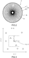
Fig. 2 ] A schematic diagram showing an example in which sensors according to the embodiment of the present invention are disposed in a turbo-machine. - [
Fig. 3 ] A graph showing an arrangement example of time series data for describing a sample entropy. - [
Fig. 4 ] A graph showing an example of the arrangement of the time series data in a case where D = 1 in the sample entropy. - [
Fig. 5 ] A graph showing an example of the arrangement of the time series data in a case where D = 2 in the sample entropy. - [
Fig. 6 ] An explanatory diagram of a method of obtaining time series data obtained by coarse graining considering a multi-scale property. - [
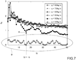
Fig. 7 ] A graph showing a result of computation using strain fluctuations of blades of the turbo-machine in a sample entropy considering the multi-scale property. - [
Fig. 8 ] A graph showing an example of time series data of pressure fluctuations for describing recurrence plots. - [
Fig. 9 ] A graph showing an example in which the time series data shown inFig. 8 is embedded in a phase space. - [
Fig. 10 ] A graph showing respective points in the phase space. - [
Fig. 11 ] A graph representing a correlation between the respective points in the phase space shown inFig. 10 as recurrence plots. - [
Fig. 12 ] A graph showing a relationship between each flow rate and DET of the recurrence plots in this embodiment. - [
Fig. 13 ] A relationship diagram of recurrence plots at a flow rate q = 6 kg/s. - [
Fig. 14 ] A relationship diagram of recurrence plots at a flow rate q = 8.5 kg/s. - [
Fig. 15 ] A relationship diagram of recurrence plots at a flow rate q = 9.5 kg/s. - [
Fig. 16 ] An explanatory diagram for capturing flutter on the basis of a relationship between each flow rate and the DET of the recurrence plots in this embodiment. - [
Fig. 17 ] A graph showing an example of the time series data for describing a permutation entropy. - [
Fig. 18 ] A diagram classifying the time series data shown inFig. 17 into permutation patterns. - [
Fig. 19 ] A graph showing existence probability of the permutation patterns shown inFig. 18 . - [
Fig. 20 ] An explanatory diagram for capturing flutter on the basis of the permutation entropy. - [
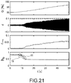
Fig. 21 ] A graph showing an example of a change over time of the permutation entropy. - [
Fig. 22 ] A block diagram showing an observation apparatus according to another embodiment of the present invention. - [
Fig. 23 ] A block diagram showing an observation apparatus according to still another embodiment of the present invention. - Hereinafter, an embodiment of the present invention will be described with reference to the drawings.
-
Fig. 1 is a block diagram showing an observation apparatus according to the embodiment of the present invention. - As shown in
Fig. 1 , anobservation apparatus 1 includes adetection unit 10, acomputation unit 20, adetermination unit 30, and acontrol unit 40. - The
detection unit 10 includes one or two or more sensors that are disposed in a turbo-machine 2, are highly time responsive, and observe unsteady fluctuations of the turbo-machine 2. - As shown in
Fig. 2 , thedetection unit 10 includes asensor 11 attached to ablade 2a which is the rotating unit of the turbo-machine 2, asensor 12 attached to awall surface 2b which is the stationary unit facing a leading end of theblade 2a, and the like. Such a sensor that is thedetection unit 10 may be disposed in a flow channel or on a wall surface in contact with the flow channel. - The
sensor 11 is constituted of, for example, a strain gauge that detects strain of the blade in real time and thesensor 12 is constituted of, for example, an unsteady pressure sensor that detects the pressure of the fluid in real time. In this embodiment, thesesensors sensor 12 may be disposed in a flow channel or on a wall surface in contact with the flow channel, for example. In order to observe stall and surge, which are unstable operations, it is sufficient to dispose sensors in a similar manner. - The
calculation unit 20 inputs output signals from thesensor 11 and thesensor 12 every moment, stores time series data for a predetermined period, and quantitatively evaluates randomness and a recurrence change on the basis of the time series data, to thereby calculate a parameter for detecting an unstable operation of the turbo-machine 2 in real time. For example, thecomputation unit 20 inputs an output signal from thesensor 11 every moment, stores time series data for a predetermined period, and calculates a parameter for detecting flutter in real time. - The
determination unit 30 compares the parameter for detecting the unstable operation with a predetermined threshold and outputs a determination result of the sign or occurrence of the unstable operation in real time. - When the
determination unit 30 outputs the determination result of the sign or occurrence of the unstable operation, thecontrol unit 40 outputs a signal for changing the operation condition to anoperation control apparatus 3 of the turbo-machine 2. Moreover, when thedetermination unit 30 outputs the determination result of the sign or occurrence of the unstable operation, thecontrol unit 40 outputs a signal for warning areporting unit 4 of an operation of the turbo-machine 2. - When the
operation control apparatus 3 receives the signal for changing the operation condition, theoperation control apparatus 3 controls the turbo-machine 2 to stop the operation of the turbo-machine 2, for example. - When the
reporting unit 4 receives the signal associated with the warning, thereporting unit 4 supplies an alarm signal for a pilot or operator to perform manual control for an aircraft, for example. - Here, as a method of calculating the detection parameter in the
computation unit 20, it is effective to use a method of calculating the detection parameter by using an index of a sample entropy, a sample entropy considering a multi-scale property, recurrence plots, or a permutation entropy. Hereinafter, the method of calculating the detection parameter by using these indices will be described. - The sample entropy refers to an index for quantitatively evaluating the randomness of the time series data. Specifically, time series data (x(ti)}, i = 1, 2, ..., N is embedded in phase spaces of D and D+1 dimensions, and the conditional probability that a point that was nearby in the D dimension is also nearby in the D+1 dimension is defined as a negative natural logarithm.
- A sample entropy SE is as follows.

- Here, the following equations are established.

- Then, for example, as shown in
Fig. 3 , θ(·) = 1 in a case where XD(tj) exists in the D-dimensional cube centered on XD(ti) and θ(·) = 0 in a case where XD(tj) does not exist in the D-dimensional cube centered on XD(ti). - Here, for example, as shown in
Fig. 4 , provided that D = 1 and the point ◇ is used as a reference, two points Δ and two points ∇ are counted. - As shown in
Fig. 5 , provided that D = 2 and the point ◇ is used as a reference, only two points Δ are counted. The points ∇ are not counted in a case where D = 2 because the points ∇ are moved outside the D-dimensional cube by extending the dimensionality. - A similar procedure is performed at all discrete points of the time series data and the sample entropy SE is calculated.
- In this embodiment, settings are performed such that a threshold r is 0.15 times as large as the standard deviation and D = 2. By setting the threshold as appropriate, it is possible to capture the sign and occurrence of the unstable operation phenomenon of the turbo-
machine 2. - The sample entropy considering the multi-scale property refers to an index for performing coarse graining on the time series data and using the sample entropy. Specifically, the time average of the time series data x(ti) is determined by nonoverlapping average as follows and new time series data y(tj) as shown in
Fig. 6 is obtained.
-
- x(ti ): Time series
- sf : Scaling factor
- y(tj ): Coarse-grained time series
- Then, the sample entropy SE is calculated by substituting this new time series data into the defined equation above.
- With the sample entropy considering the multi-scale property, it is possible to know influences of different time scales by coarse graining.
- In this embodiment, computation was performed by using circumferential strain fluctuations ε of the
blade 2a detected from thesensor 11 as x. The example is shown inFig. 7 . - As shown in A of
Fig. 7 , SE decreases in the low frequency region after Sf = 15 at the flow rate q = 9.0 kg/s. Sf(= 15) × (second-order natural frequency) substantially coincides with the sampling frequency and captures the frequency characteristics of the second-order natural frequency. Therefore, it is possible to capture the sign of flutter by detecting it. - Moreover, SE is low in the entire region at q = 9.5 kg/s. Therefore, it is possible to capture the sign of flutter by detecting it.
- The recurrence plots refer to an index for visualizing the correlation between the respective points in the phase space. For example, first of all, the time series of pressure fluctuations shown in
Fig. 8 is embedded in the phase space as shown inFig. 9 . Next, the correlation between the respective points in the phase space shown inFig. 10 is plotted as shown inFig. 11 by performing computation according to the following equation. - Here,


- In the recurrence plots, an index DET representing determinism is calculated in accordance with the following equation.

- In the equation above,
- θ: Heaviside function
- ε: threshold of distance between position vectors
- NP: total number of data points in phase space
- D: dimension of phase space (D = 5 in this embodiment)
- τ: delay time (determined based on mutual information amount in this embodiment)
- l: length of diagonal line
- lmin: minimum length defined as diagonal line
- P(l): frequency distribution function of diagonal
line having length 1. - The recurrence plots relationship at each flow rate is shown in
Figs. 12 to 15 . - Comparing
Fig. 13 withFig. 14 , it can be seen that the recurrence points are increased in the case where q = 8.5 kg/s shown inFig. 14 as compared with the case where q = 6 kg/s shown inFig. 13 . Moreover, in the case where q = 9.5 kg/s shown inFig. 15 , strong periodicity is observed with the occurrence of flutter. Thus, it can be understood that it is possible to capture the sign and occurrence of flutter by using the recurrence plots. - In
Fig. 16 , results of Stc0, Stc1, and Stc2 in which flutter is developed are analyzed. Stc0, Stc1, and Stc2 are channel names of a strain gauge that detects the strain of theblade 2a in real time. - As shown in C of
Fig. 16 , the above-mentioned index DET increases at q = 8.5 kg/s before the occurrence of flutter. It is possible to detect the sign of flutter by detecting such a slight increase in DET. Moreover, as q increases thereafter, the periodicity of the waveform increases, such that the DET also increases (D ofFig. 16 ). By detecting it, it is possible to capture the occurrence of flutter. - The permutation entropy refers to an index for quantitatively evaluating the randomness of the time series data. The time series data shown in
Fig. 17 is classified into predetermined permutation patterns as shown inFig. 18 and existence probability p of each of permutation patterns is obtained as shown inFig. 19 . The permutation entropy is calculated by applying p to the Shannon's information entropy. In general, the Shannon's information entropy is expressed by the following equation using a discrete probability distribution p of the random variable of the event. At this time, N = D!.

- Here, a permutation entropy hp means more random as it is closer to 1 and means more periodic as it is closer to 0.
- Processed results at Stc0 to Stc8 are shown in
Fig. 20 . Stc0 to Stc8 are respectively the channel names of the strain gauges that detect the strains of theblade 2a in real time. From E and F inFig. 20 , the permutation entropy decreases because the periodicity of the waveform increases as q increases. It can be seen that the occurrence of flutter can be captured by detecting it. -
Fig. 21 shows a change over time in the permutation entropy. - In
Fig. 21 , - Q: change in air flow rate over time
- ε: change in strain fluctuations over time
- εrms: change in root mean square of strain fluctuations over time.
- It can be seen from G of
Fig. 21 that the permutation entropy hp decreases to ≅ 0.85 to 0.7 at t ≅ 8.2 s before the εrms increases rapidly. It can be seen from H ofFig. 21 that the permutation entropy hp decreases to ≅ 0.85 to 0.45 at t ≅ 10 s when εrms increases rapidly. - Therefore, it is understood that although it is difficult to capture the sign and occurrence of flutter in εrms, it is possible to capture the sign and occurrence of flutter by detecting a change in permutation entropy.
- The present invention is not limited to the above-mentioned embodiments and can be implemented as various modifications and applications without departing from the technical concept of the invention. The scope of such implementation is also encompassed in the technical scope of the present invention.
- For example, as shown in
Fig. 22 , anobservation apparatus 100 may include two ormore detection units 10, two ormore computation units 20, and two ormore determination units 30. By changing the system for observation of the unstable operation into a redundant system in this manner, the reliability can be enhanced. - Moreover, as shown in
Fig. 23 , theobservation apparatus 100 may include two or more types ofdetection units 10a to 10d, two or more types ofcomputation units 20a to 20d, and two or more types ofdetermination units 30a to 30d. Accordingly, it is possible to detect more kinds of unstable operations at the same time and enhance the reliability. - In addition, the kind of unstable operations that will occur can be determined by using two or more types of sensors, two or more types of computation units, and two or more types of determination units and mounting them at suitable circumferential or axial positions in the turbo-machine.
- The computation unit(s), the determination unit(s), and the control unit(s) according to the present invention is executable by a computer. Those computation unit(s), determination unit(s), and control unit(s) may be considered as programs executable by a computer.
- The present invention can be applied to gas turbine engines for aircraft or watercraft for enhancing the safety during the operation. Moreover, the present invention can be applied to gas turbines for power generation, steam turbines, or wind turbines for power generation for monitoring the operation stability during the operation and enhancing the reliability of the electric power supply.
-
- 1
- observation apparatus
- 2
- turbo-machine
- 2a
- blade
- 2b
- wall surface
- 3
- operation control apparatus
- 4
- reporting unit
- 10
- detection unit
- 11, 12
- sensor
- 20
- computation unit
- 30
- determination unit
- 40
- control unit
- 100
- observation apparatus
Claims (8)
- An observation apparatus, comprising:a detection unit including one or two or more sensors that are disposed in a turbo-machine, are highly time responsive, and observe unsteady fluctuations of the turbo-machine;a computation unit that output signals from the one or two or more sensors every moment, stores time series data for a predetermined period, and calculates in real time a parameter for detecting an unstable operation of the turbo-machine; anda determination unit that compares the parameter for detecting the unstable operation with a predetermined threshold and outputs in real time a determination result of a sign or occurrence of the unstable operation.
- The observation apparatus according to claim 1, further comprising
a control unit that outputs, when the determination unit outputs the determination result of the sign or occurrence of the unstable operation, a signal for changing an operation condition for an operation control apparatus of the turbo-machine and/or a signal for warning of an operation of the turbo-machine. - The observation apparatus according to claim 1 or 2, wherein
the computation unit calculates the parameter for detecting the unstable operation by quantitatively evaluating randomness and a recurrence change on a basis of the time series data. - The observation apparatus according to any one of claims 1 to 3, wherein
the one or two or more sensors are disposed on a rotating unit, a stationary unit, an inside of a flow channel, or a wall surface in contact with the flow channel in the turbo-machine. - The observation apparatus according to any one of claims 1 to 4, wherein
the detection unit, the computation unit, and the determination unit include two or more detection units, two or more computation units, and two or more determination units. - The observation apparatus according to any one of claims 1 to 4, wherein
the detection unit, the computation unit, and the determination unit include two or more types of detection units, two or more types of computation units, and two or more types of determination units. - An observation method, comprising:disposing one or two or more sensors that are highly time responsive to a turbo-machine and observe unsteady fluctuations of the turbo-machine;inputting output signals from the one or two or more sensors every moment, storing time series data for a predetermined period, and calculating in real time a parameter for detecting an unstable operation of the turbo-machine; andcomparing the parameter for detecting the unstable operation with a predetermined threshold and outputting in real time a determination result of a sign or occurrence of the unstable operation.
- A program that causes a computer to execute:a step of inputting output signals from one or two or more sensors every moment one or two or more sensors that are disposed in a turbo-machine, are highly time responsive, and observe unsteady fluctuations of the turbo-machine, storing time series data for a predetermined period, and calculating in real time a parameter for detecting an unstable operation of the turbo-machine; anda step of comparing the parameter for detecting the unstable operation with a predetermined threshold and outputting in real time a determination result of a sign or occurrence of the unstable operation.
Applications Claiming Priority (2)
| Application Number | Priority Date | Filing Date | Title |
|---|---|---|---|
| JP2018079096A JP7140323B2 (en) | 2018-04-17 | 2018-04-17 | Observation device, observation method and program |
| PCT/JP2019/012401 WO2019202917A1 (en) | 2018-04-17 | 2019-03-25 | Observation device, observation method, and program |
Publications (2)
| Publication Number | Publication Date |
|---|---|
| EP3783202A1 true EP3783202A1 (en) | 2021-02-24 |
| EP3783202A4 EP3783202A4 (en) | 2021-12-29 |
Family
ID=68239516
Family Applications (1)
| Application Number | Title | Priority Date | Filing Date |
|---|---|---|---|
| EP19788439.8A Pending EP3783202A4 (en) | 2018-04-17 | 2019-03-25 | Observation device, observation method, and program |
Country Status (5)
| Country | Link |
|---|---|
| US (1) | US11629653B2 (en) |
| EP (1) | EP3783202A4 (en) |
| JP (1) | JP7140323B2 (en) |
| CA (1) | CA3097323C (en) |
| WO (1) | WO2019202917A1 (en) |
Families Citing this family (6)
| Publication number | Priority date | Publication date | Assignee | Title |
|---|---|---|---|---|
| EP3751360A1 (en) * | 2019-06-11 | 2020-12-16 | Siemens Gamesa Renewable Energy A/S | Method for computer-implemented determination of a drag coefficient of a wind turbine |
| FR3099526B1 (en) * | 2019-07-29 | 2021-08-20 | Airbus | A method and system for controlling idling speed and taking power produced by an aircraft engine. |
| US11226302B2 (en) | 2019-08-07 | 2022-01-18 | Everactive, Inc. | Steam trap monitoring devices, systems, and related techniques |
| US20210116322A1 (en) * | 2019-10-16 | 2021-04-22 | Everactive, Inc. | Monitoring techniques for pressurized systems |
| JP7406382B2 (en) * | 2020-01-16 | 2023-12-27 | 三菱重工業株式会社 | Sign detection device and sign detection method |
| JP2025034371A (en) * | 2023-08-31 | 2025-03-13 | 三菱重工業株式会社 | Sign detection device, sign detection method, and sign detection program |
Family Cites Families (13)
| Publication number | Priority date | Publication date | Assignee | Title |
|---|---|---|---|---|
| JP2002364582A (en) | 2001-06-11 | 2002-12-18 | Ishikawajima Harima Heavy Ind Co Ltd | Stall prediction method for axial compressor |
| DE10152026A1 (en) * | 2001-10-23 | 2004-02-19 | Mtu Aero Engines Gmbh | Warning of surge limit or blade damage on a turbomachine |
| JP4890095B2 (en) * | 2006-05-19 | 2012-03-07 | 株式会社Ihi | Stall sign detection device and method, and engine control system |
| JP2008014679A (en) * | 2006-07-03 | 2008-01-24 | Ritsumeikan | Equipment diagnostic method, equipment diagnostic system, and computer program |
| JP4973252B2 (en) * | 2007-03-13 | 2012-07-11 | 株式会社Ihi | Stall sign detection method and engine control system |
| JP6004392B2 (en) | 2012-05-16 | 2016-10-05 | 学校法人東京理科大学 | Apparatus and method for controlling fuel supply to combustor, and observation apparatus and method |
| US9528913B2 (en) * | 2014-07-24 | 2016-12-27 | General Electric Company | Method and systems for detection of compressor surge |
| JP6541104B2 (en) | 2015-03-17 | 2019-07-10 | 学校法人東京理科大学 | Observation apparatus and observation method |
| WO2017142707A1 (en) * | 2016-02-15 | 2017-08-24 | General Electric Company | Systems and methods for predicting an anomaly in a combustor |
| RU2016112469A (en) * | 2016-04-01 | 2017-10-04 | Фишер-Роузмаунт Системз, Инк. | METHODS AND DEVICE FOR DETECTING AND PREVENTING COMPRESSOR DIVERSION |
| JP6782943B2 (en) * | 2016-11-15 | 2020-11-11 | 大阪瓦斯株式会社 | Gas turbine abnormal condition detection device and abnormal condition detection method |
| US10662959B2 (en) * | 2017-03-30 | 2020-05-26 | General Electric Company | Systems and methods for compressor anomaly prediction |
| US10352825B2 (en) * | 2017-05-11 | 2019-07-16 | General Electric Company | Systems and methods related to detecting blowout occurrences in gas turbines |
-
2018
- 2018-04-17 JP JP2018079096A patent/JP7140323B2/en active Active
-
2019
- 2019-03-25 EP EP19788439.8A patent/EP3783202A4/en active Pending
- 2019-03-25 WO PCT/JP2019/012401 patent/WO2019202917A1/en not_active Ceased
- 2019-03-25 US US17/046,943 patent/US11629653B2/en active Active
- 2019-03-25 CA CA3097323A patent/CA3097323C/en active Active
Also Published As
| Publication number | Publication date |
|---|---|
| JP7140323B2 (en) | 2022-09-21 |
| EP3783202A4 (en) | 2021-12-29 |
| US20210164406A1 (en) | 2021-06-03 |
| WO2019202917A1 (en) | 2019-10-24 |
| US11629653B2 (en) | 2023-04-18 |
| CA3097323A1 (en) | 2019-10-24 |
| JP2019183810A (en) | 2019-10-24 |
| CA3097323C (en) | 2023-09-26 |
Similar Documents
| Publication | Publication Date | Title |
|---|---|---|
| US11629653B2 (en) | Observation apparatus, observation method, and non-transitory computer readable medium storing a program | |
| Holzinger et al. | Self-excited blade vibration experimentally investigated in transonic compressors: rotating instabilities and flutter | |
| JP6081057B2 (en) | Method and system for monitoring compressor health | |
| Pardowitz et al. | Rotating instability in an annular cascade: detailed analysis of the instationary flow phenomena | |
| EP3106856B1 (en) | Vibration fatigue testing | |
| JP5879055B2 (en) | System and method for monitoring airfoil health | |
| Barad et al. | Neural network approach for a combined performance and mechanical health monitoring of a gas turbine engine | |
| US10337414B2 (en) | Devices and methods for early prediction of impending instabilities of a system | |
| US8676514B2 (en) | System and method for monitoring health of airfoils | |
| JP2019183810A5 (en) | ||
| Champ et al. | Incipient surge detection in large volume energy systems based on Wigner–Ville distribution evaluated on vibration signals | |
| US11378488B2 (en) | System and method for optimizing passive control strategies of oscillatory instabilities in turbulent systems using finite-time Lyapunov exponents | |
| Dong et al. | Further investigation on acoustic stall-warning approach in compressors | |
| KR102786155B1 (en) | Plant monitoring device, plant monitoring method, and program | |
| RU2493549C1 (en) | Method of diagnosing input device of aircraft propulsion unit | |
| EP3810992B1 (en) | Acoustic flashback detection in a gas turbine combustion section | |
| CN114611562A (en) | Gas turbine moving blade fracture fault identification method | |
| JP2023549025A (en) | Gas turbine mass difference detection system and method | |
| Qi et al. | Aerodynamic and structural numerical investigation of full annulus last stage of steam turbine under low load conditions | |
| Liu et al. | Correlation measure-based stall margin estimation for a single-stage axial compressor | |
| Dong et al. | Causal Inference-Based Fault Diagnosis and Abnormal Degradation Detection for Aero-Engine | |
| Pawlak | A non-linear observer in the warning system indicating faulty modes of operation of a turbine jet engine | |
| US20210131910A1 (en) | System and method for determining the amplitude of oscillatory instabilities in fluid mechanical devices | |
| Albeesh | Stall Predication in Jet Compressor Blades Using Autocorrelation and ESD Model | |
| Wirkowski | Modelling the characteristics of axial compressor with variable stator vanes |
Legal Events
| Date | Code | Title | Description |
|---|---|---|---|
| STAA | Information on the status of an ep patent application or granted ep patent |
Free format text: STATUS: THE INTERNATIONAL PUBLICATION HAS BEEN MADE |
|
| PUAI | Public reference made under article 153(3) epc to a published international application that has entered the european phase |
Free format text: ORIGINAL CODE: 0009012 |
|
| STAA | Information on the status of an ep patent application or granted ep patent |
Free format text: STATUS: REQUEST FOR EXAMINATION WAS MADE |
|
| 17P | Request for examination filed |
Effective date: 20201116 |
|
| AK | Designated contracting states |
Kind code of ref document: A1 Designated state(s): AL AT BE BG CH CY CZ DE DK EE ES FI FR GB GR HR HU IE IS IT LI LT LU LV MC MK MT NL NO PL PT RO RS SE SI SK SM TR |
|
| AX | Request for extension of the european patent |
Extension state: BA ME |
|
| DAV | Request for validation of the european patent (deleted) | ||
| DAX | Request for extension of the european patent (deleted) | ||
| A4 | Supplementary search report drawn up and despatched |
Effective date: 20211201 |
|
| RIC1 | Information provided on ipc code assigned before grant |
Ipc: F23R 3/00 20060101ALI20211125BHEP Ipc: F04D 27/02 20060101ALI20211125BHEP Ipc: F02C 9/00 20060101ALI20211125BHEP Ipc: F02C 7/00 20060101ALI20211125BHEP Ipc: F01D 25/00 20060101AFI20211125BHEP |
|
| STAA | Information on the status of an ep patent application or granted ep patent |
Free format text: STATUS: EXAMINATION IS IN PROGRESS |
|
| 17Q | First examination report despatched |
Effective date: 20230418 |
|
| REG | Reference to a national code |
Ref country code: DE Ref legal event code: R079 Free format text: PREVIOUS MAIN CLASS: F01D0025000000 Ipc: F01D0021000000 |
|
| GRAP | Despatch of communication of intention to grant a patent |
Free format text: ORIGINAL CODE: EPIDOSNIGR1 |
|
| STAA | Information on the status of an ep patent application or granted ep patent |
Free format text: STATUS: GRANT OF PATENT IS INTENDED |
|
| RIC1 | Information provided on ipc code assigned before grant |
Ipc: F01D 21/00 20060101AFI20260114BHEP Ipc: F01D 21/14 20060101ALI20260114BHEP Ipc: F01D 25/00 20060101ALI20260114BHEP Ipc: F02C 9/00 20060101ALI20260114BHEP Ipc: F23R 3/00 20060101ALI20260114BHEP Ipc: F01D 25/04 20060101ALI20260114BHEP Ipc: F04D 27/00 20060101ALI20260114BHEP Ipc: F04D 29/66 20060101ALI20260114BHEP Ipc: F23R 3/28 20060101ALI20260114BHEP |
|
| INTG | Intention to grant announced |
Effective date: 20260130 |