EP3782911A1 - Engine wing - Google Patents
Engine wing Download PDFInfo
- Publication number
- EP3782911A1 EP3782911A1 EP20190666.6A EP20190666A EP3782911A1 EP 3782911 A1 EP3782911 A1 EP 3782911A1 EP 20190666 A EP20190666 A EP 20190666A EP 3782911 A1 EP3782911 A1 EP 3782911A1
- Authority
- EP
- European Patent Office
- Prior art keywords
- engine
- wing
- gas turbine
- fan
- turbine engine
- Prior art date
- Legal status (The legal status is an assumption and is not a legal conclusion. Google has not performed a legal analysis and makes no representation as to the accuracy of the status listed.)
- Granted
Links
Images


Classifications
-
- B—PERFORMING OPERATIONS; TRANSPORTING
- B64—AIRCRAFT; AVIATION; COSMONAUTICS
- B64D—EQUIPMENT FOR FITTING IN OR TO AIRCRAFT; FLIGHT SUITS; PARACHUTES; ARRANGEMENT OR MOUNTING OF POWER PLANTS OR PROPULSION TRANSMISSIONS IN AIRCRAFT
- B64D29/00—Power-plant nacelles, fairings or cowlings
- B64D29/02—Power-plant nacelles, fairings or cowlings associated with wings
-
- B—PERFORMING OPERATIONS; TRANSPORTING
- B64—AIRCRAFT; AVIATION; COSMONAUTICS
- B64C—AEROPLANES; HELICOPTERS
- B64C5/00—Stabilising surfaces
- B64C5/10—Stabilising surfaces adjustable
-
- B—PERFORMING OPERATIONS; TRANSPORTING
- B64—AIRCRAFT; AVIATION; COSMONAUTICS
- B64C—AEROPLANES; HELICOPTERS
- B64C7/00—Structures or fairings not otherwise provided for
-
- B—PERFORMING OPERATIONS; TRANSPORTING
- B64—AIRCRAFT; AVIATION; COSMONAUTICS
- B64C—AEROPLANES; HELICOPTERS
- B64C9/00—Adjustable control surfaces or members, e.g. rudders
- B64C9/02—Mounting or supporting thereof
-
- B—PERFORMING OPERATIONS; TRANSPORTING
- B64—AIRCRAFT; AVIATION; COSMONAUTICS
- B64D—EQUIPMENT FOR FITTING IN OR TO AIRCRAFT; FLIGHT SUITS; PARACHUTES; ARRANGEMENT OR MOUNTING OF POWER PLANTS OR PROPULSION TRANSMISSIONS IN AIRCRAFT
- B64D27/00—Arrangement or mounting of power plants in aircraft; Aircraft characterised by the type or position of power plants
- B64D27/02—Aircraft characterised by the type or position of power plants
- B64D27/10—Aircraft characterised by the type or position of power plants of gas-turbine type
- B64D27/12—Aircraft characterised by the type or position of power plants of gas-turbine type within, or attached to, wings
-
- B—PERFORMING OPERATIONS; TRANSPORTING
- B64—AIRCRAFT; AVIATION; COSMONAUTICS
- B64D—EQUIPMENT FOR FITTING IN OR TO AIRCRAFT; FLIGHT SUITS; PARACHUTES; ARRANGEMENT OR MOUNTING OF POWER PLANTS OR PROPULSION TRANSMISSIONS IN AIRCRAFT
- B64D27/00—Arrangement or mounting of power plants in aircraft; Aircraft characterised by the type or position of power plants
- B64D27/02—Aircraft characterised by the type or position of power plants
- B64D27/16—Aircraft characterised by the type or position of power plants of jet type
- B64D27/18—Aircraft characterised by the type or position of power plants of jet type within, or attached to, wings
-
- B—PERFORMING OPERATIONS; TRANSPORTING
- B64—AIRCRAFT; AVIATION; COSMONAUTICS
- B64D—EQUIPMENT FOR FITTING IN OR TO AIRCRAFT; FLIGHT SUITS; PARACHUTES; ARRANGEMENT OR MOUNTING OF POWER PLANTS OR PROPULSION TRANSMISSIONS IN AIRCRAFT
- B64D29/00—Power-plant nacelles, fairings or cowlings
-
- F—MECHANICAL ENGINEERING; LIGHTING; HEATING; WEAPONS; BLASTING
- F02—COMBUSTION ENGINES; HOT-GAS OR COMBUSTION-PRODUCT ENGINE PLANTS
- F02C—GAS-TURBINE PLANTS; AIR INTAKES FOR JET-PROPULSION PLANTS; CONTROLLING FUEL SUPPLY IN AIR-BREATHING JET-PROPULSION PLANTS
- F02C7/00—Features, components parts, details or accessories, not provided for in, or of interest apart form groups F02C1/00 - F02C6/00; Air intakes for jet-propulsion plants
-
- F—MECHANICAL ENGINEERING; LIGHTING; HEATING; WEAPONS; BLASTING
- F02—COMBUSTION ENGINES; HOT-GAS OR COMBUSTION-PRODUCT ENGINE PLANTS
- F02C—GAS-TURBINE PLANTS; AIR INTAKES FOR JET-PROPULSION PLANTS; CONTROLLING FUEL SUPPLY IN AIR-BREATHING JET-PROPULSION PLANTS
- F02C7/00—Features, components parts, details or accessories, not provided for in, or of interest apart form groups F02C1/00 - F02C6/00; Air intakes for jet-propulsion plants
- F02C7/04—Air intakes for gas-turbine plants or jet-propulsion plants
-
- F—MECHANICAL ENGINEERING; LIGHTING; HEATING; WEAPONS; BLASTING
- F02—COMBUSTION ENGINES; HOT-GAS OR COMBUSTION-PRODUCT ENGINE PLANTS
- F02C—GAS-TURBINE PLANTS; AIR INTAKES FOR JET-PROPULSION PLANTS; CONTROLLING FUEL SUPPLY IN AIR-BREATHING JET-PROPULSION PLANTS
- F02C7/00—Features, components parts, details or accessories, not provided for in, or of interest apart form groups F02C1/00 - F02C6/00; Air intakes for jet-propulsion plants
- F02C7/20—Mounting or supporting of plant; Accommodating heat expansion or creep
-
- F—MECHANICAL ENGINEERING; LIGHTING; HEATING; WEAPONS; BLASTING
- F02—COMBUSTION ENGINES; HOT-GAS OR COMBUSTION-PRODUCT ENGINE PLANTS
- F02K—JET-PROPULSION PLANTS
- F02K1/00—Plants characterised by the form or arrangement of the jet pipe or nozzle; Jet pipes or nozzles peculiar thereto
- F02K1/002—Plants characterised by the form or arrangement of the jet pipe or nozzle; Jet pipes or nozzles peculiar thereto with means to modify the direction of thrust vector
- F02K1/006—Plants characterised by the form or arrangement of the jet pipe or nozzle; Jet pipes or nozzles peculiar thereto with means to modify the direction of thrust vector within one plane only
-
- F—MECHANICAL ENGINEERING; LIGHTING; HEATING; WEAPONS; BLASTING
- F02—COMBUSTION ENGINES; HOT-GAS OR COMBUSTION-PRODUCT ENGINE PLANTS
- F02K—JET-PROPULSION PLANTS
- F02K1/00—Plants characterised by the form or arrangement of the jet pipe or nozzle; Jet pipes or nozzles peculiar thereto
- F02K1/78—Other construction of jet pipes
- F02K1/82—Jet pipe walls, e.g. liners
-
- F—MECHANICAL ENGINEERING; LIGHTING; HEATING; WEAPONS; BLASTING
- F02—COMBUSTION ENGINES; HOT-GAS OR COMBUSTION-PRODUCT ENGINE PLANTS
- F02K—JET-PROPULSION PLANTS
- F02K3/00—Plants including a gas turbine driving a compressor or a ducted fan
- F02K3/02—Plants including a gas turbine driving a compressor or a ducted fan in which part of the working fluid by-passes the turbine and combustion chamber
- F02K3/04—Plants including a gas turbine driving a compressor or a ducted fan in which part of the working fluid by-passes the turbine and combustion chamber the plant including ducted fans, i.e. fans with high volume, low pressure outputs, for augmenting the jet thrust, e.g. of double-flow type
- F02K3/06—Plants including a gas turbine driving a compressor or a ducted fan in which part of the working fluid by-passes the turbine and combustion chamber the plant including ducted fans, i.e. fans with high volume, low pressure outputs, for augmenting the jet thrust, e.g. of double-flow type with front fan
-
- F—MECHANICAL ENGINEERING; LIGHTING; HEATING; WEAPONS; BLASTING
- F05—INDEXING SCHEMES RELATING TO ENGINES OR PUMPS IN VARIOUS SUBCLASSES OF CLASSES F01-F04
- F05D—INDEXING SCHEME FOR ASPECTS RELATING TO NON-POSITIVE-DISPLACEMENT MACHINES OR ENGINES, GAS-TURBINES OR JET-PROPULSION PLANTS
- F05D2220/00—Application
- F05D2220/30—Application in turbines
- F05D2220/32—Application in turbines in gas turbines
- F05D2220/323—Application in turbines in gas turbines for aircraft propulsion, e.g. jet engines
-
- F—MECHANICAL ENGINEERING; LIGHTING; HEATING; WEAPONS; BLASTING
- F05—INDEXING SCHEMES RELATING TO ENGINES OR PUMPS IN VARIOUS SUBCLASSES OF CLASSES F01-F04
- F05D—INDEXING SCHEME FOR ASPECTS RELATING TO NON-POSITIVE-DISPLACEMENT MACHINES OR ENGINES, GAS-TURBINES OR JET-PROPULSION PLANTS
- F05D2220/00—Application
- F05D2220/30—Application in turbines
- F05D2220/32—Application in turbines in gas turbines
- F05D2220/328—Application in turbines in gas turbines providing direct vertical lift
-
- F—MECHANICAL ENGINEERING; LIGHTING; HEATING; WEAPONS; BLASTING
- F05—INDEXING SCHEMES RELATING TO ENGINES OR PUMPS IN VARIOUS SUBCLASSES OF CLASSES F01-F04
- F05D—INDEXING SCHEME FOR ASPECTS RELATING TO NON-POSITIVE-DISPLACEMENT MACHINES OR ENGINES, GAS-TURBINES OR JET-PROPULSION PLANTS
- F05D2220/00—Application
- F05D2220/90—Application in vehicles adapted for vertical or short take off and landing (v/stol vehicles)
-
- F—MECHANICAL ENGINEERING; LIGHTING; HEATING; WEAPONS; BLASTING
- F05—INDEXING SCHEMES RELATING TO ENGINES OR PUMPS IN VARIOUS SUBCLASSES OF CLASSES F01-F04
- F05D—INDEXING SCHEME FOR ASPECTS RELATING TO NON-POSITIVE-DISPLACEMENT MACHINES OR ENGINES, GAS-TURBINES OR JET-PROPULSION PLANTS
- F05D2240/00—Components
- F05D2240/10—Stators
- F05D2240/12—Fluid guiding means, e.g. vanes
-
- F—MECHANICAL ENGINEERING; LIGHTING; HEATING; WEAPONS; BLASTING
- F05—INDEXING SCHEMES RELATING TO ENGINES OR PUMPS IN VARIOUS SUBCLASSES OF CLASSES F01-F04
- F05D—INDEXING SCHEME FOR ASPECTS RELATING TO NON-POSITIVE-DISPLACEMENT MACHINES OR ENGINES, GAS-TURBINES OR JET-PROPULSION PLANTS
- F05D2240/00—Components
- F05D2240/10—Stators
- F05D2240/14—Casings or housings protecting or supporting assemblies within
-
- F—MECHANICAL ENGINEERING; LIGHTING; HEATING; WEAPONS; BLASTING
- F05—INDEXING SCHEMES RELATING TO ENGINES OR PUMPS IN VARIOUS SUBCLASSES OF CLASSES F01-F04
- F05D—INDEXING SCHEME FOR ASPECTS RELATING TO NON-POSITIVE-DISPLACEMENT MACHINES OR ENGINES, GAS-TURBINES OR JET-PROPULSION PLANTS
- F05D2240/00—Components
- F05D2240/90—Mounting on supporting structures or systems
- F05D2240/91—Mounting on supporting structures or systems on a stationary structure
Definitions
- a gas turbine engine typically includes a fan section, a compressor section, a combustor section, and a turbine section. Air entering the compressor section is compressed and delivered into the combustor section where it is mixed with fuel and ignited to generate a high-speed exhaust gas flow. The high-speed exhaust gas flow expands through the turbine section to drive the compressor and the fan section.
- the compressor section typically includes low and high pressure compressors, and the turbine section includes low and high pressure turbines.
- a gas turbine engine comprising, an engine wing.
- the engine wing is a first engine wing
- the gas turbine engine includes a second engine wing arranged on an opposite side of the gas turbine engine as the first engine wing.
- the gas turbine engine includes a fan and a fan case surrounding the fan. Further, the first engine wing and the second engine wing project radially outward from the fan case.
- the gas turbine engine includes a nacelle surrounding the fan case, and the first engine wing and second engine wing project radially outward beyond the nacelle.
- the nacelle includes a first cutout configured to permit the first engine wing to project radially outward from the nacelle and a second cutout configured to permit the second engine wing to project radially outward from the nacelle.
- the first engine wing and the second engine wing project radially outward from a respective side of the nacelle by a distance within a range between 0.30 and 0.74 of a diameter of the fan.
- the distance is about 0.59 of the diameter of the fan.
- the first engine wing and the second engine wing are airfoil-shaped in cross-section.
- the first engine wing and the second engine wing have a first chord adjacent the nacelle and a second chord less than the first chord adjacent respective tips of the first engine wing and the second engine wing.
- the first chord is about 0.46 of the diameter of the fan and the second chord is about 0.30 of the diameter of the fan.
- the cross-section of the first engine wing and second engine wing at a particular position along the longitudinal axis of the engine wing has a maximum thickness within a range of 0.04 to 0.12 of the chord of the respective first engine wing and second engine wing at that particular position.
- leading edges of the first engine wing and the second engine wing are swept aft relative to a plane normal to an engine central longitudinal axis by about 15 degrees.
- the gas turbine engine includes a geared architecture connecting a fan to a shaft of the gas turbine engine such that the fan is driven at a lower speed than the shaft.
- an airplane comprising an engine wing projecting outward of a housing surrounding a gas turbine engine.
- the airplane includes a fuselage and first and second wings projecting from the fuselage.
- the first and second wings are configured to generate a lifting force to assist support of the airplane in flight.
- the engine wing is a first engine wing projecting from the housing of the gas turbine engine
- the airplane includes a second engine wing projecting from the housing of the gas turbine engine.
- the gas turbine engine is a first gas turbine engine
- the airplane includes a third engine wing and a fourth engine wing projecting from a housing of a second gas turbine engine.
- the first gas turbine engine is mounted to the first wing and the second gas turbine engine is mounted to the second wing.
- the engine wing projects radially outward beyond a nacelle.
- FIG. 1 schematically illustrates a gas turbine engine 20.
- the gas turbine engine 20 is disclosed herein as a two-spool turbofan that generally incorporates a fan section 22, a compressor section 24, a combustor section 26 and a turbine section 28.
- the fan section 22 drives air along a bypass flow path B in a bypass duct defined within a housing 15, such as a fan case, and also drives air along a core flow path C for compression and communication into the combustor section 26 then expansion through the turbine section 28.
- the exemplary engine 20 generally includes a low speed spool 30 and a high speed spool 32 mounted for rotation about an engine central longitudinal axis A relative to an engine static structure 36 via several bearing systems 38. It should be understood that various bearing systems 38 at various locations may alternatively or additionally be provided, and the location of bearing systems 38 may be varied as appropriate to the application.
- the low speed spool 30 generally includes an inner shaft 40 that interconnects, a first (or low) pressure compressor 44 and a first (or low) pressure turbine 46.
- the inner shaft 40 is connected to the fan 42 through a speed change mechanism, which in exemplary gas turbine engine 20 is illustrated as a geared architecture 48 to drive a fan 42 at a lower speed than the low speed spool 30.
- the high speed spool 32 includes an outer shaft 50 that interconnects a second (or high) pressure compressor 52 and a second (or high) pressure turbine 54.
- a combustor 56 is arranged in exemplary gas turbine 20 between the high pressure compressor 52 and the high pressure turbine 54.
- a mid-turbine frame 57 of the engine static structure 36 may be arranged generally between the high pressure turbine 54 and the low pressure turbine 46.
- the mid-turbine frame 57 further supports bearing systems 38 in the turbine section 28.
- the inner shaft 40 and the outer shaft 50 are concentric and rotate via bearing systems 38 about the engine central longitudinal axis A which is colline
- the core airflow is compressed by the low pressure compressor 44 then the high pressure compressor 52, mixed and burned with fuel in the combustor 56, then expanded over the high pressure turbine 54 and low pressure turbine 46.
- the mid-turbine frame 57 includes airfoils 59 which are in the core airflow path C.
- the turbines 46, 54 rotationally drive the respective low speed spool 30 and high speed spool 32 in response to the expansion.
- gear system 48 may be located aft of the low pressure compressor, or aft of the combustor section 26 or even aft of turbine section 28, and fan 42 may be positioned forward or aft of the location of gear system 48.
- the engine 20 in one example is a high-bypass geared aircraft engine.
- the engine 20 bypass ratio is greater than about 6:1, with an example embodiment being greater than about 10:1
- the geared architecture 48 is an epicyclic gear train, such as a planetary gear system or other gear system, with a gear reduction ratio of greater than about 2.3:1 and the low pressure turbine 46 has a pressure ratio that is greater than about five.
- the engine 20 bypass ratio is greater than about 10:1
- the fan diameter is significantly larger than that of the low pressure compressor 44
- the low pressure turbine 46 has a pressure ratio that is greater than about 5:1.
- the low pressure turbine 46 pressure ratio is pressure measured prior to the inlet of low pressure turbine 46 as related to the pressure at the outlet of the low pressure turbine 46 prior to an exhaust nozzle.
- the geared architecture 48 may be an epicycle gear train, such as a planetary gear system or other gear system, with a gear reduction ratio of greater than about 2.3:1 and less than about 5:1. It should be understood, however, that the above parameters are only exemplary of one embodiment of a geared architecture engine and that the present invention is applicable to other gas turbine engines including but not limited to direct drive turbofans, low bypass engines, and multi-stage fan engines.
- the fan section 22 of the engine 20 is designed for a particular flight condition -- typically cruise at about 0.8 Mach and about 35,000 feet (10,668 meters).
- the flight condition of 0.8 Mach and 35,000 ft (10,668 meters), with the engine at its best fuel consumption - also known as "bucket cruise Thrust Specific Fuel Consumption ('TSFC')" - is the industry standard parameter of lbm of fuel being burned divided by lbf of thrust the engine produces at that minimum point.
- "Low fan pressure ratio” is the pressure ratio across the fan blade alone, without a Fan Exit Guide Vane (“FEGV”) system.
- the low fan pressure ratio as disclosed herein according to one non-limiting embodiment is less than about 1.45:1.
- the "Low corrected fan tip speed” as disclosed herein according to one non-limiting embodiment is less than about 1150 ft / second (350.5 meters/second).
- Figure 2 illustrates an airplane 60 including a fuselage 62, first and second wings 64, 66 projecting from the fuselage 62 and configured to generate a lifting force to support the airplane 60 in flight.
- the airplane 60 includes two gas turbine engines, namely a first gas turbine engine 68 mounted below the first wing 64 and a second gas turbine engine 70 mounted below the second wing 66.
- the first and second gas turbine engines 68, 70 may be configured substantially similar to the gas turbine engine 20.
- the first and second gas turbine engines 68, 70 may each include a geared architecture, substantially similar to geared architecture 48, for example, connecting a fan of the respective gas turbine engine 68, 70 to a shaft of the respective gas turbine engine 68, 70.
- the fans are driven at a lower speed than the shaft, such as a low speed spool.
- this disclosure has particular benefits in the context of gas turbine engines which include a geared architecture, however this disclosure may be used relative to other types of gas turbine engines, including those without a geared architecture.
- first and second engine wings 72, 74 project radially outwardly from opposite sides of the first gas turbine engine 68
- third and fourth engine wings 76, 78 project radially outwardly from opposite sides of the second gas turbine engine 70. While four engine wings are shown in Figure 2 , this disclosure extends to gas turbine engines and airplanes with one or more engine wings. Details of the engine wings will be described below.
- the engine wings 72, 74, 76, 78 are configured to produce lift while the airplane 60 moves through the air. Specifically, the engine wings 72, 74, 76, 78 are configured to produce an amount of lift that offsets at least some of the weight of the gas turbine engines 68, 70, such as any increased weight that may be attributable to the presence of a geared architecture.
- Figure 3 is representative of the lifting force L 1 produced by the wing 66, lifting force L 2 produced by engine wing 78, and the weight W of the gas turbine engine 70.
- the lifting force L 2 at least partially offsets the weight W.
- the engine wings 72, 74, 76, 78 are distinguishable from various known aircraft and engine structures such as propellers, airfoils (i.e., blades or vanes), and strakes.
- a propeller is configured to rotate about an engine central longitudinal axis during operation, whereas the engine wings 72, 74, 76, 78 are not.
- Airfoils, such as blades or vanes are arranged substantially within a gas turbine bypass flow path in a bypass duct or in a core flow path, whereas the engine wings 72, 74, 76, 78 are not.
- some engines include fin-like strakes projecting outwardly from a nacelle, those strakes are not configured to produce lift. Rather, strakes are configured to produce a vortex that flows over top of a wing and maintains attached flow.
- the fore-most edge 80 of the engine wing 78 is adjacent a fore-most edge 82 of a housing 84 surrounding the gas turbine engine 70.
- the housing 84 may be a nacelle or a portion of a nacelle such as a fan or inlet cowl.
- Positioning the engine wings in a forward location relative to the gas turbine engines is beneficial particularly in applications where the gas turbine engines include a geared architecture, which is typically located toward the forward end of the engine.
- the engine wings are able to produce a lifting force which serves to more evenly distribute the weight of the gas turbine engine.
- the engine wings are directly mounted to a gas turbine engine.
- the engine wings 72, 74 are directly mounted to a housing 86 of the gas turbine engine 68.
- the engine wings 76, 78 are mounted similarly to the gas turbine engine 70.
- the housing 86 is substantially similar to the housing 15 described relative to Figure 1 , and in particular is a fan case surrounding a fan of the gas turbine engine 68 in this example.
- the engine wings 72, 74 are rigidly attached to the housing 86 by welding, for example.
- the engine wings 72, 74 have a variable pitch and are rotatable relative to the housing 86 by rotation about respective longitudinal axes A 1 , A 2 , which extend in a generally port-starboard direction substantially normal to the engine central longitudinal axis A 3 of the gas turbine engine 68.
- the gas turbine engine 68 may be mounted to the wing 64 by way of a pylon 88. Further, when mounted to the wing 64, the gas turbine engine 68 may be surrounded by nacelle 90, various components of which are shown in an exploded view in Figure 4 .
- the nacelle 90 in this example, includes first and second thrust reverser sections 92, 94, first and second fan cowl sections 96, 98, and an inlet cowl 100.
- the first and second fan cowl sections 96, 98 include cutouts 102, 104 permitting the engine wings 72, 74 to project radially, relative to the engine central longitudinal axis A 3 outward beyond the nacelle 90.
- Each first and second fan cowl section 96, 98 may be configured to separate at a seam 106, 108 adjacent the respective cutout 102, 104 such that the first and second fan cowl sections 96, 98 can be opened for engine maintenance, for example, without interfering with the engine wings 72, 74.
- the size of the engine wings 72, 74, 76, 78 will now be described relative to Figure 5 and engine wing 72. It should be understood that the engine wings 74, 76, 78 are sized and arranged substantially similar to engine wing 72. In this disclosure, the size of the engine wing 72 is configured to provide a lift force that serves to counteract the weight of the gas turbine engine 68 and, in effect, distributes the weight of the geared architecture, which would otherwise be weighted toward a forward portion of the gas turbine engine 68.
- the engine wing 72 projects radially outward from the nacelle 90, namely the fan cowl section 96, by a distance D 1 within a range between 0.30 and 0.74 of (i.e., multiplied by) a diameter of the fan D 2 ( Figure 4 ).
- the diameter of the fan D 2 in this example is an inner diameter of the housing 86 and D 2 may alternatively be the inner diameter of the nacelle 90.
- the distance D 1 is about 0.59 of the diameter of the fan D 2 .
- the engine wings 72, 74, 76, 78 are airfoil-shaped in cross-section.
- the engine wing 72 has a first chord C 1 adjacent the nacelle 90 and a second chord C 2 less than the first chord C 1 adjacent a tip 110 of the engine wing 72.
- the first chord C 1 is about 0.46 of the diameter of the fan D 2 and the second chord C 2 is about 0.30 of the diameter of the fan D 2 While the first chord C 1 is typically greater than the second chord C 2 , either can be within range of 0.35 to 0.58 of a diameter of the fan D 2 in other examples.
- the engine wing 72 has a maximum thickness T within a range of 0.04 to 0.12 of the chord of the engine wing 72 at that particular location along the longitudinal axis A 1 .
- the maximum thickness is about 0.08 of the chord at a particular location along the longitudinal axis A 1 .
- a leading edge 112 of the engine wing 72 is swept aft relative to a plane normal N to an engine central longitudinal axis A 3 by an angle ⁇ 1 of about 15 degrees.
- the angle ⁇ 1 can be anywhere from 0 to 25 degrees in other examples.
- the component may be an electronic, mechanical, or electromechanical component which is electronically and/or fluidly connected to various other components of the gas turbine engine 68.
- the component 114 can include an oil tank, or a heat exchanger such as an air-oil cooler or a fuel-air cooler, a variable frequency generator, and/or other components.
- the arrangement of the engine wing 72 radially outside the nacelle 90 makes the engine wing 72 effective as a heat sink.
- the engine wings 72, 74, 76, 78 may be variable pitch.
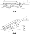
- Figure 6A illustrates an example in which the engine wing 78 is a variable pitch engine wing and is configured to rotate about a longitudinal axis A 4 extending along the length of the engine wing 78 in the generally port-starboard direction. It should be understood that the engine wings 72, 74, 76 may be similarly configured.
- the airplane 60 is in a cruise condition.
- the engine wing 78 is configured to rotate about axis A 4 in a counterclockwise direction by an angle ⁇ 2 of up to 10° and in a clockwise direction by an angle ⁇ 3 of up to 10° relative to the angle of attack ⁇ A of the airplane 60.
- the angle of attack ⁇ A is substantially zero and is substantially parallel to freestream flow F.
- Figure 6B illustrates the engine wing 78 with the airplane 60 in a climb condition in which the angle of attack ⁇ A of the airplane 60 is about 29° relative to the freestream flow F.
- the engine wing 78 may be rotated 10° in either a clockwise or counterclockwise direction by up to 10° relative to the freestream flow F. While 10° is mentioned, this disclosure extends to other angles of rotation of the engine wings.
Landscapes
- Engineering & Computer Science (AREA)
- Chemical & Material Sciences (AREA)
- Combustion & Propulsion (AREA)
- Aviation & Aerospace Engineering (AREA)
- Mechanical Engineering (AREA)
- General Engineering & Computer Science (AREA)
- Structures Of Non-Positive Displacement Pumps (AREA)
Abstract
Description
- A gas turbine engine typically includes a fan section, a compressor section, a combustor section, and a turbine section. Air entering the compressor section is compressed and delivered into the combustor section where it is mixed with fuel and ignited to generate a high-speed exhaust gas flow. The high-speed exhaust gas flow expands through the turbine section to drive the compressor and the fan section. The compressor section typically includes low and high pressure compressors, and the turbine section includes low and high pressure turbines.
- According to a first aspect of the present invention there is provided, a gas turbine engine comprising, an engine wing.
- In an embodiment of the above embodiment, the engine wing is a first engine wing, and the gas turbine engine includes a second engine wing arranged on an opposite side of the gas turbine engine as the first engine wing.
- In an embodiment of any of the above embodiments, the gas turbine engine includes a fan and a fan case surrounding the fan. Further, the first engine wing and the second engine wing project radially outward from the fan case.
- In an embodiment of any of the above embodiments, the gas turbine engine includes a nacelle surrounding the fan case, and the first engine wing and second engine wing project radially outward beyond the nacelle.
- In an embodiment of any of the above embodiments, the nacelle includes a first cutout configured to permit the first engine wing to project radially outward from the nacelle and a second cutout configured to permit the second engine wing to project radially outward from the nacelle.
- In an embodiment of any of the above embodiments, the first engine wing and the second engine wing project radially outward from a respective side of the nacelle by a distance within a range between 0.30 and 0.74 of a diameter of the fan.
- In an embodiment of any of the above embodiments, the distance is about 0.59 of the diameter of the fan.
- In an embodiment of any of the above embodiments, the first engine wing and the second engine wing are airfoil-shaped in cross-section.
- In an embodiment of any of the above embodiments, the first engine wing and the second engine wing have a first chord adjacent the nacelle and a second chord less than the first chord adjacent respective tips of the first engine wing and the second engine wing.
- In an embodiment of any of the above embodiments, the first chord is about 0.46 of the diameter of the fan and the second chord is about 0.30 of the diameter of the fan.
- In an embodiment of any of the above embodiments, the cross-section of the first engine wing and second engine wing at a particular position along the longitudinal axis of the engine wing has a maximum thickness within a range of 0.04 to 0.12 of the chord of the respective first engine wing and second engine wing at that particular position.
- In an embodiment of any of the above embodiments, leading edges of the first engine wing and the second engine wing are swept aft relative to a plane normal to an engine central longitudinal axis by about 15 degrees.
- In an embodiment of any of the above embodiments, the gas turbine engine includes a geared architecture connecting a fan to a shaft of the gas turbine engine such that the fan is driven at a lower speed than the shaft.
- According to a second aspect of the present invention there is provided an airplane comprising an engine wing projecting outward of a housing surrounding a gas turbine engine.
- In an embodiment of any of the above embodiments, the airplane includes a fuselage and first and second wings projecting from the fuselage. The first and second wings are configured to generate a lifting force to assist support of the airplane in flight.
- In an embodiment of any of the above embodiments, the engine wing is a first engine wing projecting from the housing of the gas turbine engine, and the airplane includes a second engine wing projecting from the housing of the gas turbine engine.
- In an embodiment of any of the above embodiments, the gas turbine engine is a first gas turbine engine, and the airplane includes a third engine wing and a fourth engine wing projecting from a housing of a second gas turbine engine.
- In an embodiment of any of the above embodiments, the first gas turbine engine is mounted to the first wing and the second gas turbine engine is mounted to the second wing.
- In an embodiment of any of the above embodiments, the engine wing projects radially outward beyond a nacelle.
- In an embodiment of any of the above embodiments, wherein a heat exchanger is mounted within the engine wing.
-
-
Figure 1 schematically illustrates a gas turbine engine. -
Figure 2 illustrates an embodiment of an airplane according to the present invention from a front view. -
Figure 3 illustrates the airplane ofFigure 2 from a side view. -
Figure 4 illustrates an example gas turbine engine according to the present invention with the nacelle shown in an exploded view. -
Figure 5 illustrates a portion of the example gas turbine engine ofFigure 4 , and in particular illustrates the arrangement of an example engine wing. -
Figure 6A illustrates an example variable pitch engine wing according to the present invention and an airplane in a cruise condition. -
Figure 6B illustrates the example variable pitch engine wing ofFigure 6A and the airplane in a climb condition. -
Figure 1 schematically illustrates agas turbine engine 20. Thegas turbine engine 20 is disclosed herein as a two-spool turbofan that generally incorporates afan section 22, acompressor section 24, a combustor section 26 and aturbine section 28. Thefan section 22 drives air along a bypass flow path B in a bypass duct defined within ahousing 15, such as a fan case, and also drives air along a core flow path C for compression and communication into the combustor section 26 then expansion through theturbine section 28. Although depicted as a two-spool turbofan gas turbine engine in the disclosed non-limiting embodiment, it should be understood that the concepts described herein are not limited to use with two-spool turbofans as the teachings may be applied to other types of turbine engines including but not limited to three-spool architectures. - The
exemplary engine 20 generally includes alow speed spool 30 and ahigh speed spool 32 mounted for rotation about an engine central longitudinal axis A relative to an enginestatic structure 36 viaseveral bearing systems 38. It should be understood thatvarious bearing systems 38 at various locations may alternatively or additionally be provided, and the location ofbearing systems 38 may be varied as appropriate to the application. - The
low speed spool 30 generally includes aninner shaft 40 that interconnects, a first (or low)pressure compressor 44 and a first (or low)pressure turbine 46. Theinner shaft 40 is connected to thefan 42 through a speed change mechanism, which in exemplarygas turbine engine 20 is illustrated as a gearedarchitecture 48 to drive afan 42 at a lower speed than thelow speed spool 30. Thehigh speed spool 32 includes anouter shaft 50 that interconnects a second (or high)pressure compressor 52 and a second (or high)pressure turbine 54. Acombustor 56 is arranged inexemplary gas turbine 20 between thehigh pressure compressor 52 and thehigh pressure turbine 54. Amid-turbine frame 57 of the enginestatic structure 36 may be arranged generally between thehigh pressure turbine 54 and thelow pressure turbine 46. Themid-turbine frame 57 further supports bearingsystems 38 in theturbine section 28. Theinner shaft 40 and theouter shaft 50 are concentric and rotate viabearing systems 38 about the engine central longitudinal axis A which is collinear with their longitudinal axes. - The core airflow is compressed by the
low pressure compressor 44 then thehigh pressure compressor 52, mixed and burned with fuel in thecombustor 56, then expanded over thehigh pressure turbine 54 andlow pressure turbine 46. Themid-turbine frame 57 includesairfoils 59 which are in the core airflow path C. Theturbines low speed spool 30 andhigh speed spool 32 in response to the expansion. It will be appreciated that each of the positions of thefan section 22,compressor section 24, combustor section 26,turbine section 28, and fandrive gear system 48 may be varied. For example,gear system 48 may be located aft of the low pressure compressor, or aft of the combustor section 26 or even aft ofturbine section 28, andfan 42 may be positioned forward or aft of the location ofgear system 48. - The
engine 20 in one example is a high-bypass geared aircraft engine. In a further example, theengine 20 bypass ratio is greater than about 6:1, with an example embodiment being greater than about 10:1, the gearedarchitecture 48 is an epicyclic gear train, such as a planetary gear system or other gear system, with a gear reduction ratio of greater than about 2.3:1 and thelow pressure turbine 46 has a pressure ratio that is greater than about five. In one disclosed embodiment, theengine 20 bypass ratio is greater than about 10:1, the fan diameter is significantly larger than that of thelow pressure compressor 44, and thelow pressure turbine 46 has a pressure ratio that is greater than about 5:1. Thelow pressure turbine 46 pressure ratio is pressure measured prior to the inlet oflow pressure turbine 46 as related to the pressure at the outlet of thelow pressure turbine 46 prior to an exhaust nozzle. The gearedarchitecture 48 may be an epicycle gear train, such as a planetary gear system or other gear system, with a gear reduction ratio of greater than about 2.3:1 and less than about 5:1. It should be understood, however, that the above parameters are only exemplary of one embodiment of a geared architecture engine and that the present invention is applicable to other gas turbine engines including but not limited to direct drive turbofans, low bypass engines, and multi-stage fan engines. - A significant amount of thrust is provided by the bypass flow B due to the high bypass ratio. The
fan section 22 of theengine 20 is designed for a particular flight condition -- typically cruise at about 0.8 Mach and about 35,000 feet (10,668 meters). The flight condition of 0.8 Mach and 35,000 ft (10,668 meters), with the engine at its best fuel consumption - also known as "bucket cruise Thrust Specific Fuel Consumption ('TSFC')" - is the industry standard parameter of lbm of fuel being burned divided by lbf of thrust the engine produces at that minimum point. "Low fan pressure ratio" is the pressure ratio across the fan blade alone, without a Fan Exit Guide Vane ("FEGV") system. The low fan pressure ratio as disclosed herein according to one non-limiting embodiment is less than about 1.45:1. "Low corrected fan tip speed" is the actual fan tip speed in ft/sec divided by an industry standard temperature correction of [(Tram °R) / (518.7 °R)]0.5 (where °R = K x 9/5). The "Low corrected fan tip speed" as disclosed herein according to one non-limiting embodiment is less than about 1150 ft / second (350.5 meters/second). -
Figure 2 illustrates anairplane 60 including afuselage 62, first andsecond wings fuselage 62 and configured to generate a lifting force to support theairplane 60 in flight. In this example, theairplane 60 includes two gas turbine engines, namely a firstgas turbine engine 68 mounted below thefirst wing 64 and a secondgas turbine engine 70 mounted below thesecond wing 66. - The first and second
gas turbine engines gas turbine engine 20. In particular, the first and secondgas turbine engines architecture 48, for example, connecting a fan of the respectivegas turbine engine gas turbine engine gas turbine engines - While a geared architecture has known benefits, it may add weight relative to a gas turbine engine that is similarly sized but without a geared architecture. In this disclosure, at least one engine wing projects from the gas turbine engines. In particular, in
Figure 2 , first andsecond engine wings gas turbine engine 68, and third andfourth engine wings gas turbine engine 70. While four engine wings are shown inFigure 2 , this disclosure extends to gas turbine engines and airplanes with one or more engine wings. Details of the engine wings will be described below. - The
engine wings airplane 60 moves through the air. Specifically, theengine wings gas turbine engines Figure 3 is representative of the lifting force L1 produced by thewing 66, lifting force L2 produced byengine wing 78, and the weight W of thegas turbine engine 70. Here, again, the lifting force L2 at least partially offsets the weight W. - In general, the
engine wings engine wings engine wings - As shown in
Figure 3 , thefore-most edge 80 of theengine wing 78 is adjacent afore-most edge 82 of ahousing 84 surrounding thegas turbine engine 70. Thehousing 84 may be a nacelle or a portion of a nacelle such as a fan or inlet cowl. Positioning the engine wings in a forward location relative to the gas turbine engines is beneficial particularly in applications where the gas turbine engines include a geared architecture, which is typically located toward the forward end of the engine. Thus, the engine wings are able to produce a lifting force which serves to more evenly distribute the weight of the gas turbine engine. - In one example of this disclosure, the engine wings are directly mounted to a gas turbine engine. With reference to
Figure 4 , theengine wings housing 86 of thegas turbine engine 68. Theengine wings gas turbine engine 70. Thehousing 86 is substantially similar to thehousing 15 described relative toFigure 1 , and in particular is a fan case surrounding a fan of thegas turbine engine 68 in this example. - In one example, the
engine wings housing 86 by welding, for example. In another example, theengine wings housing 86 by rotation about respective longitudinal axes A1, A2, which extend in a generally port-starboard direction substantially normal to the engine central longitudinal axis A3 of thegas turbine engine 68. - The
gas turbine engine 68 may be mounted to thewing 64 by way of apylon 88. Further, when mounted to thewing 64, thegas turbine engine 68 may be surrounded bynacelle 90, various components of which are shown in an exploded view inFigure 4 . Thenacelle 90, in this example, includes first and secondthrust reverser sections fan cowl sections inlet cowl 100. In this disclosure, to accommodate theengine wings fan cowl sections cutouts engine wings nacelle 90. Each first and secondfan cowl section seam respective cutout fan cowl sections engine wings - The size of the
engine wings Figure 5 andengine wing 72. It should be understood that theengine wings engine wing 72. In this disclosure, the size of theengine wing 72 is configured to provide a lift force that serves to counteract the weight of thegas turbine engine 68 and, in effect, distributes the weight of the geared architecture, which would otherwise be weighted toward a forward portion of thegas turbine engine 68. - In the example of
Figure 5 , theengine wing 72 projects radially outward from thenacelle 90, namely thefan cowl section 96, by a distance D1 within a range between 0.30 and 0.74 of (i.e., multiplied by) a diameter of the fan D2 (Figure 4 ). The diameter of the fan D2 in this example is an inner diameter of thehousing 86 and D2 may alternatively be the inner diameter of thenacelle 90. In a particular example, the distance D1 is about 0.59 of the diameter of the fan D2. - The
engine wings Figure 5 , theengine wing 72 has a first chord C1 adjacent thenacelle 90 and a second chord C2 less than the first chord C1 adjacent atip 110 of theengine wing 72. Further, the first chord C1 is about 0.46 of the diameter of the fan D2 and the second chord C2 is about 0.30 of the diameter of the fan D2 While the first chord C1 is typically greater than the second chord C2, either can be within range of 0.35 to 0.58 of a diameter of the fan D2 in other examples. Further, in cross-section, theengine wing 72 has a maximum thickness T within a range of 0.04 to 0.12 of the chord of theengine wing 72 at that particular location along the longitudinal axis A1. In one example, the maximum thickness is about 0.08 of the chord at a particular location along the longitudinal axis A1. - In
Figure 5 , aleading edge 112 of theengine wing 72 is swept aft relative to a plane normal N to an engine central longitudinal axis A3 by an angle θ1 of about 15 degrees. The angle θ1 can be anywhere from 0 to 25 degrees in other examples. - Given the size and location of the
engine wings gas turbine engines engine wings Figure 5 . The component may be an electronic, mechanical, or electromechanical component which is electronically and/or fluidly connected to various other components of thegas turbine engine 68. The component 114 can include an oil tank, or a heat exchanger such as an air-oil cooler or a fuel-air cooler, a variable frequency generator, and/or other components. The arrangement of theengine wing 72 radially outside thenacelle 90 makes theengine wing 72 effective as a heat sink. - As mentioned above, the
engine wings Figure 6A illustrates an example in which theengine wing 78 is a variable pitch engine wing and is configured to rotate about a longitudinal axis A4 extending along the length of theengine wing 78 in the generally port-starboard direction. It should be understood that theengine wings - In
Figure 6A , theairplane 60 is in a cruise condition. With reference toFigure 6A , theengine wing 78 is configured to rotate about axis A4 in a counterclockwise direction by an angle θ2 of up to 10° and in a clockwise direction by an angle θ3 of up to 10° relative to the angle of attack θA of theairplane 60. InFigure 6A , the angle of attack θA is substantially zero and is substantially parallel to freestream flow F. -
Figure 6B illustrates theengine wing 78 with theairplane 60 in a climb condition in which the angle of attack θA of theairplane 60 is about 29° relative to the freestream flow F. Again, theengine wing 78 may be rotated 10° in either a clockwise or counterclockwise direction by up to 10° relative to the freestream flow F. While 10° is mentioned, this disclosure extends to other angles of rotation of the engine wings. - It should be understood that terms such as "axial," "radial," and "circumferential" are used above with reference to the normal operational attitude of the
engines - Although the different examples have the specific components shown in the illustrations, embodiments of this disclosure are not limited to those particular combinations. It is possible to use some of the components or features from one of the examples in combination with features or components from another one of the examples. In addition, the various figures accompanying this disclosure are not necessarily to scale, and some features may be exaggerated or minimized to show certain details of a particular component or arrangement.
- One of ordinary skill in this art would understand that the above-described embodiments are exemplary and non-limiting. That is, modifications of this disclosure would come within the scope of the claims. Accordingly, the following claims should be studied to determine their true scope and content.
Claims (15)
- A gas turbine engine (68), comprising:
an engine wing (72). - The gas turbine engine (68) as recited in claim 1, wherein:the engine wing (72) is a first engine wing (72), andthe gas turbine engine (68) includes a second engine wing (74) arranged on an opposite side of the gas turbine engine (68) as the first engine wing (72).
- The gas turbine engine (68) as recited in claim 1 or 2, further comprising:a fan (42); anda fan case (86) surrounding the fan (42), wherein the first engine wing (72) and the second engine wing (74) project radially outward from the fan case (86).
- The gas turbine engine (68) as recited in claim 3, further comprising a nacelle (90) surrounding the fan case (86), wherein the first engine wing (72) and second engine wing (74) project radially outward beyond the nacelle (90) and, optionally, the first engine wing (72) and the second engine wing (74) are airfoil-shaped in cross-section.
- The gas turbine engine (68) as recited in claim 4, wherein the nacelle (90) includes a first cutout (102) configured to permit the first engine wing (72) to project radially outward from the nacelle (90) and a second cutout (104) configured to permit the second engine wing (74) to project radially outward from the nacelle (90).
- The gas turbine engine (68) as recited in claim 4 or 5, wherein the first engine wing (72) and the second engine wing (74) project radially outward from a respective side of the nacelle (90) by a distance (D1) within a range between 0.30 and 0.74 of a diameter (D2) of the fan (42), and optionally, the distance (D1) is about 0.59 of the diameter (D2) of the fan (42).
- The gas turbine engine (68) as recited in any of claims 4 to 6, wherein the first engine wing (72) and the second engine wing (74) have a first chord (Ci) adjacent the nacelle (90) and a second chord (C2) less than the first chord (Ci) adjacent respective tips (110) of the first engine wing (72) and the second engine wing (74), and, optionally, the first chord (Ci) is about 0.46 of the diameter (D2) of the fan (42) and the second chord (C2) is about 0.30 of the diameter (D2) of the fan (42).
- The gas turbine engine (68) as recited in any of claims 1 to 7, wherein the cross-section of the first engine wing (72) and second engine wing (74) has a maximum thickness (T) within a range of 0.04 to 0.12 of the chord of the respective first engine wing (72) and second engine wing (74).
- The gas turbine engine (68) as recited in any of claims 1 to 8, wherein leading edges of the first engine wing (72) and the second engine wing (74) are swept aft relative to a plane normal (N) to an engine central longitudinal axis (A3) by about 15 degrees.
- The gas turbine engine (68, 20) as recited in any of claims 1 to 9, further comprising a geared architecture (48) connecting a fan (42) to a shaft of the gas turbine engine (68, 20) such that the fan (42) is driven at a lower speed than the shaft.
- An airplane (60), comprising:
an engine wing (72) projecting outward of a housing (84) surrounding a gas turbine engine (20). - The airplane (60) as recited in claim 11, further comprising:a fuselage (62);first and second wings (72, 74) projecting from the fuselage (62) and configured to generate a lifting force (L2) to support the airplane (60) in flight.
- The airplane (60) as recited in claim 12, wherein the engine wing (72) is a first engine wing (72) projecting from the housing (84) of the gas turbine engine (20), and wherein the airplane (60) includes a second engine wing (74) projecting from the housing (86) of the gas turbine engine (20) or the engine wing (72, 74, 76, 78) projects radially outward beyond a nacelle (90).
- The airplane (60) as recited in claim 13, wherein the gas turbine engine (20) is a first gas turbine engine (68), and the airplane (60) includes a third engine wing (76) and a fourth engine wing (78) projecting from a housing (84) of a second gas turbine engine (70) and, optionally the first gas turbine engine (68) is mounted to the first wing (72) and the second gas turbine engine (70) is mounted to the second wing (74).
- The airplane (60) as recited in any of claims 1 to 14, wherein a heat exchanger is mounted within the engine wing (72).
Applications Claiming Priority (2)
| Application Number | Priority Date | Filing Date | Title |
|---|---|---|---|
| US201916549329A | 2019-08-23 | 2019-08-23 | |
| US16/574,424 US10730635B1 (en) | 2019-08-23 | 2019-09-18 | Engine wing |
Publications (2)
| Publication Number | Publication Date |
|---|---|
| EP3782911A1 true EP3782911A1 (en) | 2021-02-24 |
| EP3782911B1 EP3782911B1 (en) | 2022-12-14 |
Family
ID=71838802
Family Applications (1)
| Application Number | Title | Priority Date | Filing Date |
|---|---|---|---|
| EP20190666.6A Active EP3782911B1 (en) | 2019-08-23 | 2020-08-12 | Engine wing |
Country Status (2)
| Country | Link |
|---|---|
| US (1) | US10730635B1 (en) |
| EP (1) | EP3782911B1 (en) |
Families Citing this family (1)
| Publication number | Priority date | Publication date | Assignee | Title |
|---|---|---|---|---|
| US20260110262A1 (en) * | 2024-10-22 | 2026-04-23 | Rtx Corporation | Hydrogen assisted combustion and engine cooling |
Citations (6)
| Publication number | Priority date | Publication date | Assignee | Title |
|---|---|---|---|---|
| US2907536A (en) * | 1950-10-04 | 1959-10-06 | Helmut Ph G A R Von Zborowski | Annular wing flying machine and method of flying same |
| US20050011993A1 (en) * | 2003-07-18 | 2005-01-20 | Konings Christopher A. | Nacelle chine installation for drag reduction |
| US20110315827A1 (en) * | 2009-03-12 | 2011-12-29 | Bob Collins | Wing Extension Control Surface |
| US20130045087A1 (en) * | 2010-04-27 | 2013-02-21 | Marcio Carmo Lopes Pontes | Airfoil combination for aircraft turbofan |
| WO2015016731A1 (en) * | 2013-07-30 | 2015-02-05 | Pchentleshev Valery Turkubeevich | Aircraft (variants) |
| EP3205581A1 (en) * | 2016-02-13 | 2017-08-16 | MRA Systems, Inc. | Aircraft and empennage section of an aircraft |
Family Cites Families (16)
| Publication number | Priority date | Publication date | Assignee | Title |
|---|---|---|---|---|
| US2306015A (en) * | 1938-03-25 | 1942-12-22 | Dornier Claude | Wing structure for aircraft |
| US2257940A (en) * | 1938-06-22 | 1941-10-07 | Dornier Werke Gmbh | Airplane having a liftable pusher plant |
| US2744745A (en) * | 1954-05-27 | 1956-05-08 | William E Engelhard | Sealed annealing apparatus |
| US2969935A (en) * | 1957-09-09 | 1961-01-31 | Carl C Price | Convertible aircraft |
| US3744745A (en) * | 1971-09-30 | 1973-07-10 | Mc Donnell Douglas Corp | Liftvanes |
| GB2196390B (en) * | 1986-10-16 | 1991-06-26 | Rolls Royce Plc | Intake for turbopropeller gas turbine engine. |
| GB2203105B (en) * | 1987-04-06 | 1990-11-28 | Rolls Royce Plc | Wing mounted ducted fan gas turbine powerplant |
| US6698687B2 (en) * | 2002-02-13 | 2004-03-02 | The Boeing Company | Aircraft wing heat exchanger apparatus and method |
| US8408491B2 (en) * | 2007-04-24 | 2013-04-02 | United Technologies Corporation | Nacelle assembly having inlet airfoil for a gas turbine engine |
| FR2987602B1 (en) | 2012-03-02 | 2014-02-28 | Aircelle Sa | TURBOMOTEUR NACELLE EQUIPPED WITH A HEAT EXCHANGER |
| WO2014130103A2 (en) | 2013-02-20 | 2014-08-28 | United Technologies Corporation | Integrated heat exchangers for low fan pressure ratio geared turbofan |
| US9429072B2 (en) | 2013-05-22 | 2016-08-30 | General Electric Company | Return fluid air cooler system for turbine cooling with optional power extraction |
| US9533754B2 (en) * | 2014-04-19 | 2017-01-03 | The Boeing Company | Wing aerial refueling system |
| US9803557B2 (en) | 2015-01-20 | 2017-10-31 | United Technologies Corporation | Gas turbine engine and blocker door assembly |
| WO2016209350A2 (en) * | 2015-04-24 | 2016-12-29 | Sikorsky Aircraft Corporation | Landing gear fairing with aerodynamic surfaces for tail sitter aircraft |
| US9982630B2 (en) | 2015-05-26 | 2018-05-29 | Pratt & Whitney Canada Corp. | Turbofan bypass air cooled oil cooler fairings |
-
2019
- 2019-09-18 US US16/574,424 patent/US10730635B1/en active Active
-
2020
- 2020-08-12 EP EP20190666.6A patent/EP3782911B1/en active Active
Patent Citations (6)
| Publication number | Priority date | Publication date | Assignee | Title |
|---|---|---|---|---|
| US2907536A (en) * | 1950-10-04 | 1959-10-06 | Helmut Ph G A R Von Zborowski | Annular wing flying machine and method of flying same |
| US20050011993A1 (en) * | 2003-07-18 | 2005-01-20 | Konings Christopher A. | Nacelle chine installation for drag reduction |
| US20110315827A1 (en) * | 2009-03-12 | 2011-12-29 | Bob Collins | Wing Extension Control Surface |
| US20130045087A1 (en) * | 2010-04-27 | 2013-02-21 | Marcio Carmo Lopes Pontes | Airfoil combination for aircraft turbofan |
| WO2015016731A1 (en) * | 2013-07-30 | 2015-02-05 | Pchentleshev Valery Turkubeevich | Aircraft (variants) |
| EP3205581A1 (en) * | 2016-02-13 | 2017-08-16 | MRA Systems, Inc. | Aircraft and empennage section of an aircraft |
Also Published As
| Publication number | Publication date |
|---|---|
| US10730635B1 (en) | 2020-08-04 |
| EP3782911B1 (en) | 2022-12-14 |
Similar Documents
| Publication | Publication Date | Title |
|---|---|---|
| US11781447B2 (en) | Low pressure ratio fan engine having a dimensional relationship between inlet and fan size | |
| US11015550B2 (en) | Low pressure ratio fan engine having a dimensional relationship between inlet and fan size | |
| EP2964924B1 (en) | Gas turbine engine inlet | |
| EP3199766A1 (en) | Variable pitch fan blade arrangement for gas turbine engine | |
| US20160108854A1 (en) | Low pressure ratio fan engine having a dimensional relationship between inlet and fan size | |
| EP3090126B1 (en) | Gas turbine engine component comprising endwall countouring trench | |
| US20200023981A1 (en) | Pylon shape with geared turbofan for structural stiffness | |
| EP2971656B1 (en) | Aerodynamic track fairing for a gas turbine engine fan nacelle | |
| EP3094823B1 (en) | Gas turbine engine component and corresponding gas turbine engine | |
| US11473434B2 (en) | Gas turbine engine airfoil | |
| EP3782911B1 (en) | Engine wing | |
| US20200080442A1 (en) | Airfoil assembly for a gas turbine engine | |
| US10227884B2 (en) | Fan platform with leading edge tab | |
| EP3121430B1 (en) | A nacelle assembly | |
| US10450898B2 (en) | Track fairing assembly for a turbine engine nacelle | |
| EP3156627A1 (en) | Low pressure ratio fan engine having a dimensional relationship between inlet and fan size | |
| WO2014099085A2 (en) | Gas turbine engine with forward moment arm | |
| US20160298633A1 (en) | Shortened support for compressor variable vane |
Legal Events
| Date | Code | Title | Description |
|---|---|---|---|
| PUAI | Public reference made under article 153(3) epc to a published international application that has entered the european phase |
Free format text: ORIGINAL CODE: 0009012 |
|
| STAA | Information on the status of an ep patent application or granted ep patent |
Free format text: STATUS: THE APPLICATION HAS BEEN PUBLISHED |
|
| AK | Designated contracting states |
Kind code of ref document: A1 Designated state(s): AL AT BE BG CH CY CZ DE DK EE ES FI FR GB GR HR HU IE IS IT LI LT LU LV MC MK MT NL NO PL PT RO RS SE SI SK SM TR |
|
| AX | Request for extension of the european patent |
Extension state: BA ME |
|
| STAA | Information on the status of an ep patent application or granted ep patent |
Free format text: STATUS: REQUEST FOR EXAMINATION WAS MADE |
|
| 17P | Request for examination filed |
Effective date: 20210824 |
|
| RBV | Designated contracting states (corrected) |
Designated state(s): AL AT BE BG CH CY CZ DE DK EE ES FI FR GB GR HR HU IE IS IT LI LT LU LV MC MK MT NL NO PL PT RO RS SE SI SK SM TR |
|
| REG | Reference to a national code |
Ref country code: DE Ref legal event code: R079 Ref document number: 602020006894 Country of ref document: DE Free format text: PREVIOUS MAIN CLASS: B64D0029000000 Ipc: B64C0005100000 |
|
| GRAP | Despatch of communication of intention to grant a patent |
Free format text: ORIGINAL CODE: EPIDOSNIGR1 |
|
| STAA | Information on the status of an ep patent application or granted ep patent |
Free format text: STATUS: GRANT OF PATENT IS INTENDED |
|
| RIC1 | Information provided on ipc code assigned before grant |
Ipc: F02K 1/00 20060101ALI20220614BHEP Ipc: F02K 3/06 20060101ALI20220614BHEP Ipc: F02K 1/82 20060101ALI20220614BHEP Ipc: F02C 7/20 20060101ALI20220614BHEP Ipc: F02C 7/04 20060101ALI20220614BHEP Ipc: F02C 7/00 20060101ALI20220614BHEP Ipc: B64D 29/00 20060101ALI20220614BHEP Ipc: B64D 27/18 20060101ALI20220614BHEP Ipc: B64C 7/00 20060101ALI20220614BHEP Ipc: B64C 5/10 20060101AFI20220614BHEP |
|
| INTG | Intention to grant announced |
Effective date: 20220708 |
|
| GRAS | Grant fee paid |
Free format text: ORIGINAL CODE: EPIDOSNIGR3 |
|
| GRAA | (expected) grant |
Free format text: ORIGINAL CODE: 0009210 |
|
| STAA | Information on the status of an ep patent application or granted ep patent |
Free format text: STATUS: THE PATENT HAS BEEN GRANTED |
|
| AK | Designated contracting states |
Kind code of ref document: B1 Designated state(s): AL AT BE BG CH CY CZ DE DK EE ES FI FR GB GR HR HU IE IS IT LI LT LU LV MC MK MT NL NO PL PT RO RS SE SI SK SM TR |
|
| REG | Reference to a national code |
Ref country code: GB Ref legal event code: FG4D |
|
| REG | Reference to a national code |
Ref country code: CH Ref legal event code: EP |
|
| REG | Reference to a national code |
Ref country code: DE Ref legal event code: R096 Ref document number: 602020006894 Country of ref document: DE |
|
| REG | Reference to a national code |
Ref country code: IE Ref legal event code: FG4D |
|
| REG | Reference to a national code |
Ref country code: AT Ref legal event code: REF Ref document number: 1537538 Country of ref document: AT Kind code of ref document: T Effective date: 20230115 |
|
| REG | Reference to a national code |
Ref country code: LT Ref legal event code: MG9D |
|
| REG | Reference to a national code |
Ref country code: NL Ref legal event code: MP Effective date: 20221214 |
|
| PG25 | Lapsed in a contracting state [announced via postgrant information from national office to epo] |
Ref country code: SE Free format text: LAPSE BECAUSE OF FAILURE TO SUBMIT A TRANSLATION OF THE DESCRIPTION OR TO PAY THE FEE WITHIN THE PRESCRIBED TIME-LIMIT Effective date: 20221214 Ref country code: NO Free format text: LAPSE BECAUSE OF FAILURE TO SUBMIT A TRANSLATION OF THE DESCRIPTION OR TO PAY THE FEE WITHIN THE PRESCRIBED TIME-LIMIT Effective date: 20230314 Ref country code: LT Free format text: LAPSE BECAUSE OF FAILURE TO SUBMIT A TRANSLATION OF THE DESCRIPTION OR TO PAY THE FEE WITHIN THE PRESCRIBED TIME-LIMIT Effective date: 20221214 Ref country code: FI Free format text: LAPSE BECAUSE OF FAILURE TO SUBMIT A TRANSLATION OF THE DESCRIPTION OR TO PAY THE FEE WITHIN THE PRESCRIBED TIME-LIMIT Effective date: 20221214 |
|
| REG | Reference to a national code |
Ref country code: AT Ref legal event code: MK05 Ref document number: 1537538 Country of ref document: AT Kind code of ref document: T Effective date: 20221214 |
|
| PG25 | Lapsed in a contracting state [announced via postgrant information from national office to epo] |
Ref country code: RS Free format text: LAPSE BECAUSE OF FAILURE TO SUBMIT A TRANSLATION OF THE DESCRIPTION OR TO PAY THE FEE WITHIN THE PRESCRIBED TIME-LIMIT Effective date: 20221214 Ref country code: LV Free format text: LAPSE BECAUSE OF FAILURE TO SUBMIT A TRANSLATION OF THE DESCRIPTION OR TO PAY THE FEE WITHIN THE PRESCRIBED TIME-LIMIT Effective date: 20221214 Ref country code: HR Free format text: LAPSE BECAUSE OF FAILURE TO SUBMIT A TRANSLATION OF THE DESCRIPTION OR TO PAY THE FEE WITHIN THE PRESCRIBED TIME-LIMIT Effective date: 20221214 Ref country code: GR Free format text: LAPSE BECAUSE OF FAILURE TO SUBMIT A TRANSLATION OF THE DESCRIPTION OR TO PAY THE FEE WITHIN THE PRESCRIBED TIME-LIMIT Effective date: 20230315 |
|
| P01 | Opt-out of the competence of the unified patent court (upc) registered |
Effective date: 20230521 |
|
| PG25 | Lapsed in a contracting state [announced via postgrant information from national office to epo] |
Ref country code: NL Free format text: LAPSE BECAUSE OF FAILURE TO SUBMIT A TRANSLATION OF THE DESCRIPTION OR TO PAY THE FEE WITHIN THE PRESCRIBED TIME-LIMIT Effective date: 20221214 |
|
| PG25 | Lapsed in a contracting state [announced via postgrant information from national office to epo] |
Ref country code: SM Free format text: LAPSE BECAUSE OF FAILURE TO SUBMIT A TRANSLATION OF THE DESCRIPTION OR TO PAY THE FEE WITHIN THE PRESCRIBED TIME-LIMIT Effective date: 20221214 Ref country code: RO Free format text: LAPSE BECAUSE OF FAILURE TO SUBMIT A TRANSLATION OF THE DESCRIPTION OR TO PAY THE FEE WITHIN THE PRESCRIBED TIME-LIMIT Effective date: 20221214 Ref country code: PT Free format text: LAPSE BECAUSE OF FAILURE TO SUBMIT A TRANSLATION OF THE DESCRIPTION OR TO PAY THE FEE WITHIN THE PRESCRIBED TIME-LIMIT Effective date: 20230414 Ref country code: ES Free format text: LAPSE BECAUSE OF FAILURE TO SUBMIT A TRANSLATION OF THE DESCRIPTION OR TO PAY THE FEE WITHIN THE PRESCRIBED TIME-LIMIT Effective date: 20221214 Ref country code: EE Free format text: LAPSE BECAUSE OF FAILURE TO SUBMIT A TRANSLATION OF THE DESCRIPTION OR TO PAY THE FEE WITHIN THE PRESCRIBED TIME-LIMIT Effective date: 20221214 Ref country code: CZ Free format text: LAPSE BECAUSE OF FAILURE TO SUBMIT A TRANSLATION OF THE DESCRIPTION OR TO PAY THE FEE WITHIN THE PRESCRIBED TIME-LIMIT Effective date: 20221214 Ref country code: AT Free format text: LAPSE BECAUSE OF FAILURE TO SUBMIT A TRANSLATION OF THE DESCRIPTION OR TO PAY THE FEE WITHIN THE PRESCRIBED TIME-LIMIT Effective date: 20221214 |
|
| PG25 | Lapsed in a contracting state [announced via postgrant information from national office to epo] |
Ref country code: SK Free format text: LAPSE BECAUSE OF FAILURE TO SUBMIT A TRANSLATION OF THE DESCRIPTION OR TO PAY THE FEE WITHIN THE PRESCRIBED TIME-LIMIT Effective date: 20221214 Ref country code: PL Free format text: LAPSE BECAUSE OF FAILURE TO SUBMIT A TRANSLATION OF THE DESCRIPTION OR TO PAY THE FEE WITHIN THE PRESCRIBED TIME-LIMIT Effective date: 20221214 Ref country code: IS Free format text: LAPSE BECAUSE OF FAILURE TO SUBMIT A TRANSLATION OF THE DESCRIPTION OR TO PAY THE FEE WITHIN THE PRESCRIBED TIME-LIMIT Effective date: 20230414 Ref country code: AL Free format text: LAPSE BECAUSE OF FAILURE TO SUBMIT A TRANSLATION OF THE DESCRIPTION OR TO PAY THE FEE WITHIN THE PRESCRIBED TIME-LIMIT Effective date: 20221214 |
|
| REG | Reference to a national code |
Ref country code: DE Ref legal event code: R097 Ref document number: 602020006894 Country of ref document: DE |
|
| PLBE | No opposition filed within time limit |
Free format text: ORIGINAL CODE: 0009261 |
|
| STAA | Information on the status of an ep patent application or granted ep patent |
Free format text: STATUS: NO OPPOSITION FILED WITHIN TIME LIMIT |
|
| PG25 | Lapsed in a contracting state [announced via postgrant information from national office to epo] |
Ref country code: DK Free format text: LAPSE BECAUSE OF FAILURE TO SUBMIT A TRANSLATION OF THE DESCRIPTION OR TO PAY THE FEE WITHIN THE PRESCRIBED TIME-LIMIT Effective date: 20221214 |
|
| RAP4 | Party data changed (patent owner data changed or rights of a patent transferred) |
Owner name: RTX CORPORATION |
|
| 26N | No opposition filed |
Effective date: 20230915 |
|
| PG25 | Lapsed in a contracting state [announced via postgrant information from national office to epo] |
Ref country code: SI Free format text: LAPSE BECAUSE OF FAILURE TO SUBMIT A TRANSLATION OF THE DESCRIPTION OR TO PAY THE FEE WITHIN THE PRESCRIBED TIME-LIMIT Effective date: 20221214 |
|
| PG25 | Lapsed in a contracting state [announced via postgrant information from national office to epo] |
Ref country code: MC Free format text: LAPSE BECAUSE OF FAILURE TO SUBMIT A TRANSLATION OF THE DESCRIPTION OR TO PAY THE FEE WITHIN THE PRESCRIBED TIME-LIMIT Effective date: 20221214 |
|
| REG | Reference to a national code |
Ref country code: CH Ref legal event code: PL |
|
| PG25 | Lapsed in a contracting state [announced via postgrant information from national office to epo] |
Ref country code: MC Free format text: LAPSE BECAUSE OF FAILURE TO SUBMIT A TRANSLATION OF THE DESCRIPTION OR TO PAY THE FEE WITHIN THE PRESCRIBED TIME-LIMIT Effective date: 20221214 |
|
| PG25 | Lapsed in a contracting state [announced via postgrant information from national office to epo] |
Ref country code: LU Free format text: LAPSE BECAUSE OF NON-PAYMENT OF DUE FEES Effective date: 20230812 |
|
| PG25 | Lapsed in a contracting state [announced via postgrant information from national office to epo] |
Ref country code: LU Free format text: LAPSE BECAUSE OF NON-PAYMENT OF DUE FEES Effective date: 20230812 Ref country code: CH Free format text: LAPSE BECAUSE OF NON-PAYMENT OF DUE FEES Effective date: 20230831 |
|
| REG | Reference to a national code |
Ref country code: BE Ref legal event code: MM Effective date: 20230831 |
|
| REG | Reference to a national code |
Ref country code: IE Ref legal event code: MM4A |
|
| PG25 | Lapsed in a contracting state [announced via postgrant information from national office to epo] |
Ref country code: IT Free format text: LAPSE BECAUSE OF FAILURE TO SUBMIT A TRANSLATION OF THE DESCRIPTION OR TO PAY THE FEE WITHIN THE PRESCRIBED TIME-LIMIT Effective date: 20221214 |
|
| PG25 | Lapsed in a contracting state [announced via postgrant information from national office to epo] |
Ref country code: IE Free format text: LAPSE BECAUSE OF NON-PAYMENT OF DUE FEES Effective date: 20230812 |
|
| PG25 | Lapsed in a contracting state [announced via postgrant information from national office to epo] |
Ref country code: IE Free format text: LAPSE BECAUSE OF NON-PAYMENT OF DUE FEES Effective date: 20230812 |
|
| PG25 | Lapsed in a contracting state [announced via postgrant information from national office to epo] |
Ref country code: BE Free format text: LAPSE BECAUSE OF NON-PAYMENT OF DUE FEES Effective date: 20230831 |
|
| PG25 | Lapsed in a contracting state [announced via postgrant information from national office to epo] |
Ref country code: BG Free format text: LAPSE BECAUSE OF FAILURE TO SUBMIT A TRANSLATION OF THE DESCRIPTION OR TO PAY THE FEE WITHIN THE PRESCRIBED TIME-LIMIT Effective date: 20221214 |
|
| PG25 | Lapsed in a contracting state [announced via postgrant information from national office to epo] |
Ref country code: BG Free format text: LAPSE BECAUSE OF FAILURE TO SUBMIT A TRANSLATION OF THE DESCRIPTION OR TO PAY THE FEE WITHIN THE PRESCRIBED TIME-LIMIT Effective date: 20221214 |
|
| PG25 | Lapsed in a contracting state [announced via postgrant information from national office to epo] |
Ref country code: CY Free format text: LAPSE BECAUSE OF FAILURE TO SUBMIT A TRANSLATION OF THE DESCRIPTION OR TO PAY THE FEE WITHIN THE PRESCRIBED TIME-LIMIT; INVALID AB INITIO Effective date: 20200812 |
|
| PG25 | Lapsed in a contracting state [announced via postgrant information from national office to epo] |
Ref country code: HU Free format text: LAPSE BECAUSE OF FAILURE TO SUBMIT A TRANSLATION OF THE DESCRIPTION OR TO PAY THE FEE WITHIN THE PRESCRIBED TIME-LIMIT; INVALID AB INITIO Effective date: 20200812 |
|
| REG | Reference to a national code |
Ref country code: DE Ref legal event code: R081 Ref document number: 602020006894 Country of ref document: DE Owner name: RTX CORPORATION (N.D.GES.D. STAATES DELAWARE),, US Free format text: FORMER OWNER: RAYTHEON TECHNOLOGIES CORPORATION, FARMINGTON, CT, US |
|
| PGFP | Annual fee paid to national office [announced via postgrant information from national office to epo] |
Ref country code: DE Payment date: 20250724 Year of fee payment: 6 |
|
| PGFP | Annual fee paid to national office [announced via postgrant information from national office to epo] |
Ref country code: GB Payment date: 20250725 Year of fee payment: 6 |
|
| PGFP | Annual fee paid to national office [announced via postgrant information from national office to epo] |
Ref country code: FR Payment date: 20250723 Year of fee payment: 6 |
|
| PG25 | Lapsed in a contracting state [announced via postgrant information from national office to epo] |
Ref country code: TR Free format text: LAPSE BECAUSE OF FAILURE TO SUBMIT A TRANSLATION OF THE DESCRIPTION OR TO PAY THE FEE WITHIN THE PRESCRIBED TIME-LIMIT Effective date: 20221214 |