EP3782906A1 - Staggered periodic ribblets - Google Patents
Staggered periodic ribblets Download PDFInfo
- Publication number
- EP3782906A1 EP3782906A1 EP20191888.5A EP20191888A EP3782906A1 EP 3782906 A1 EP3782906 A1 EP 3782906A1 EP 20191888 A EP20191888 A EP 20191888A EP 3782906 A1 EP3782906 A1 EP 3782906A1
- Authority
- EP
- European Patent Office
- Prior art keywords
- periodic
- riblet
- transition region
- riblets
- staggered
- Prior art date
- Legal status (The legal status is an assumption and is not a legal conclusion. Google has not performed a legal analysis and makes no representation as to the accuracy of the status listed.)
- Withdrawn
Links
Images



Classifications
-
- F—MECHANICAL ENGINEERING; LIGHTING; HEATING; WEAPONS; BLASTING
- F15—FLUID-PRESSURE ACTUATORS; HYDRAULICS OR PNEUMATICS IN GENERAL
- F15D—FLUID DYNAMICS, i.e. METHODS OR MEANS FOR INFLUENCING THE FLOW OF GASES OR LIQUIDS
- F15D1/00—Influencing flow of fluids
- F15D1/002—Influencing flow of fluids by influencing the boundary layer
- F15D1/0025—Influencing flow of fluids by influencing the boundary layer using passive means, i.e. without external energy supply
- F15D1/003—Influencing flow of fluids by influencing the boundary layer using passive means, i.e. without external energy supply comprising surface features, e.g. indentations or protrusions
- F15D1/0035—Influencing flow of fluids by influencing the boundary layer using passive means, i.e. without external energy supply comprising surface features, e.g. indentations or protrusions in the form of riblets
- F15D1/004—Influencing flow of fluids by influencing the boundary layer using passive means, i.e. without external energy supply comprising surface features, e.g. indentations or protrusions in the form of riblets oriented essentially parallel to the direction of flow
-
- B—PERFORMING OPERATIONS; TRANSPORTING
- B64—AIRCRAFT; AVIATION; COSMONAUTICS
- B64C—AEROPLANES; HELICOPTERS
- B64C21/00—Influencing air flow over aircraft surfaces by affecting boundary layer flow
- B64C21/10—Influencing air flow over aircraft surfaces by affecting boundary layer flow using other surface properties, e.g. roughness
-
- F—MECHANICAL ENGINEERING; LIGHTING; HEATING; WEAPONS; BLASTING
- F01—MACHINES OR ENGINES IN GENERAL; ENGINE PLANTS IN GENERAL; STEAM ENGINES
- F01D—NON-POSITIVE DISPLACEMENT MACHINES OR ENGINES, e.g. STEAM TURBINES
- F01D5/00—Blades; Blade-carrying members; Heating, heat-insulating, cooling or antivibration means on the blades or the members
- F01D5/12—Blades
- F01D5/14—Form or construction
- F01D5/141—Shape, i.e. outer, aerodynamic form
- F01D5/145—Means for influencing boundary layers or secondary circulations
-
- B—PERFORMING OPERATIONS; TRANSPORTING
- B64—AIRCRAFT; AVIATION; COSMONAUTICS
- B64C—AEROPLANES; HELICOPTERS
- B64C2230/00—Boundary layer controls
- B64C2230/26—Boundary layer controls by using rib lets or hydrophobic surfaces
-
- F—MECHANICAL ENGINEERING; LIGHTING; HEATING; WEAPONS; BLASTING
- F15—FLUID-PRESSURE ACTUATORS; HYDRAULICS OR PNEUMATICS IN GENERAL
- F15D—FLUID DYNAMICS, i.e. METHODS OR MEANS FOR INFLUENCING THE FLOW OF GASES OR LIQUIDS
- F15D1/00—Influencing flow of fluids
- F15D1/10—Influencing flow of fluids around bodies of solid material
-
- Y—GENERAL TAGGING OF NEW TECHNOLOGICAL DEVELOPMENTS; GENERAL TAGGING OF CROSS-SECTIONAL TECHNOLOGIES SPANNING OVER SEVERAL SECTIONS OF THE IPC; TECHNICAL SUBJECTS COVERED BY FORMER USPC CROSS-REFERENCE ART COLLECTIONS [XRACs] AND DIGESTS
- Y02—TECHNOLOGIES OR APPLICATIONS FOR MITIGATION OR ADAPTATION AGAINST CLIMATE CHANGE
- Y02T—CLIMATE CHANGE MITIGATION TECHNOLOGIES RELATED TO TRANSPORTATION
- Y02T50/00—Aeronautics or air transport
- Y02T50/10—Drag reduction
-
- Y—GENERAL TAGGING OF NEW TECHNOLOGICAL DEVELOPMENTS; GENERAL TAGGING OF CROSS-SECTIONAL TECHNOLOGIES SPANNING OVER SEVERAL SECTIONS OF THE IPC; TECHNICAL SUBJECTS COVERED BY FORMER USPC CROSS-REFERENCE ART COLLECTIONS [XRACs] AND DIGESTS
- Y02—TECHNOLOGIES OR APPLICATIONS FOR MITIGATION OR ADAPTATION AGAINST CLIMATE CHANGE
- Y02T—CLIMATE CHANGE MITIGATION TECHNOLOGIES RELATED TO TRANSPORTATION
- Y02T50/00—Aeronautics or air transport
- Y02T50/60—Efficient propulsion technologies, e.g. for aircraft
Definitions
- This disclosure generally relates to riblets, and more specifically to staggered periodic riblets.
- An object e.g., an aircraft or a marine vessel
- a fluid e.g., air or water
- An increase in the drag force experienced by the object increases the energy required for the object to move through the fluid.
- an increase in the drag force experienced by an aircraft moving at an established speed may increase the power required by the aircraft to move through the air at the same established speed.
- drag force has a significant impact of aircraft fuel consumption and aircraft range.
- a physical object includes a smooth surface, first periodic riblets on the smooth surface of a physical object, and second periodic riblets on the smooth surface of the physical object.
- Each first periodic riblet comprises a first transition region at a first end of each first periodic riblet and a second transition region at a second end of each first periodic riblet.
- Each second periodic riblet comprises a first transition region at a first end of each second periodic riblet and a second transition region at a second end of each second periodic riblet.
- Each second transition region at the second end of each first periodic riblet overlaps each first transition region at the first end of each second periodic riblet.
- a method of manufacturing a physical object includes forming first periodic riblets on a smooth surface of a physical object. The method further includes forming second periodic riblets on the smooth surface of the physical object.
- Each first periodic riblet comprises a first transition region at a first end of each first periodic riblet and a second transition region at a second end of each first periodic riblet.
- Each second periodic riblet comprises a first transition region at a first end of each second periodic riblet and a second transition region at a second end of each second periodic riblet.
- Each second transition region at the second end of each first periodic riblet overlaps each first transition region at the first end of each second periodic riblet.
- Embodiments of this disclosure describe physical objects having staggered periodic riblets that may be used to reduce drag, which includes pressure drag and friction drag, over the surfaces of the physical objects.
- Riblets are very small (e.g., less than a hundredth of an inch in depth) grooves or channels on a surface of a physical object (e.g., a vehicle).
- the riblets run parallel to the direction of flow.
- Staggered periodic riblets are riblets with overlapping regions. Staggered periodic riblets are located above a smooth surface of the physical object.
- Certain three-dimensional (3D) riblet structures may reduce skin friction drag due to reduced wetted area. However, these 3D riblet structures may generate additional pressure drag due to the added frontal area of the surface feature.
- the staggered periodic riblets described herein increase the drag reducing benefits of riblets by significantly reducing or eliminating the pressure drag penalty as compared to certain other 3D riblet structures.
- Staggered periodic riblets may maintain a constant cross sectional area in the streamwise flow direction. The constant cross sectional area is achieved by compensating the decreasing volume of the trailing edge of each staggered periodic riblet with the increasing volume of the neighboring staggered periodic riblets.
- embodiments of this disclosure use staggered periodic riblets to reduce and/or eliminate the pressure drag penalty as compared to certain other periodic riblets.
- FIGURES 1 through 5 show example apparatuses and methods associated with staggered periodic riblets.
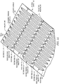
- FIGURE 1A shows an example physical object with staggered periodic riblets and FIGURE 1B shows an example longitudinal section of the physical object of FIGURE 1A .
- FIGURE 2A shows an example cross section of a protruding riblet pattern and FIGURE 2B shows an example cross section of a staggered riblet pattern.
- FIGURE 3A shows an example pressure output pattern associated with a physical object having a protruding riblet pattern and FIGURE 3B shows an example pressure output pattern associated with a physical object having a staggered riblet pattern.
- FIGURE 4 shows an example bar chart that compares drag produced by a physical object having a protruding riblet pattern to a physical object having a staggered riblet pattern.
- FIGURE 5 shows an example method for reducing drag on a surface using a staggered riblet pattern.
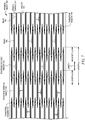
- FIGURE 6 shows a physical object with staggered periodic riblets having a different size and shape than the staggered periodic riblets of FIGURE 1A
- FIGURE 7 shows a physical object with staggered periodic riblets having a different size, shape, and arrangement than the staggered periodic riblets of FIGURE 1A .
- Physical object 100 is any object that is susceptible to drag (e.g., skin friction drag and pressure drag.)
- physical object 100 may be a component (e.g., a portion of an outer body) of an aircraft (e.g., an airplane, a helicopter, a blimp, a drone, etc.), a component of a marine vessel (e.g., a cargo ship, a passenger ship, a canoe, a raft, etc.), a component of a motorized vehicle (e.g., a truck, a car, a a train, a scooter, etc.), a component of a non-motorized vehicle (e.g., a bicycle, a skateboard, etc.), a component of a spacecraft (e.g., a spaceship, a satellite, etc.), a wind turbine, a projectile (e.g., a missile), or any other physical object that is capable of experiencing drag.
- a component of an outer body of an aircraft e.g
- drag may be generated by a force acting opposite to the relative motion of physical object 100 (e.g., a wing of an aircraft) moving with respect to a surrounding fluid (e.g., air).
- drag is generated by the viscosity of gas.
- drag may be generated due to the viscosity of a fluid (e.g., water) near the surface of physical object 100 (e.g., a section of a pipe or duct.)
- Physical object 100 includes a smooth surface 104.
- smooth surface 104 of physical object 100 is flat.
- smooth surface 104 of physical object 100 may have a curvature.
- Staggered periodic riblets 102 of physical object 100 may be formed on smooth surface 104.
- Staggered periodic riblets 102 of physical object 100 are staggered such that each staggered periodic riblet 102 overlaps at least one other staggered periodic riblet 102 in plan view.
- Each staggered periodic riblet 102 is located above a plane (e.g., plane 180 of FIGURE 1B ) of smooth surface 104 of physical object 100.
- a cross sectional area as measured above smooth surface 104 of physical object 100 is approximately (i.e., within five percent) the same at any cross section through staggered periodic riblets 102.
- Each staggered periodic riblet 102 includes a peak 106.
- Each peak 106 of each staggered periodic riblet 102 is a point along an exterior surface of staggered periodic riblet 102 that is farthest away from the plane of smooth surface 104 in a direction away from physical object 100.
- peaks 106 of staggered periodic riblets 102 extend a predetermined distance (e.g., 0.002 inches) above the plane of smooth surface 104 of physical object 100.
- one or more peaks 106 of one or more staggered periodic riblets 102 may form a pointed tip.
- one or more peaks 106 of one or more staggered periodic riblets 102 may form a flat or rounded peak surface.
- the spaces between adjacent staggered periodic riblets 102 create valleys 108.
- Each valley 108 between adjacent staggered periodic riblets 102 is an area along an exterior surface of staggered periodic riblet 102 that is closest to the plane of smooth surface 104.
- valleys 108 of staggered periodic riblets 102 are located along the plane of smooth surface 104 of physical object 100.
- Each staggered periodic riblet 102 includes two transition regions 145.
- a first transition region 145 is located at a first end of each staggered periodic riblet 102 and a second transition region 145 is located at a second end of each staggered periodic riblet 102.
- Each transition region 145 of each staggered periodic riblet 102 slopes down from peak 106 to smooth surface 104.
- each transition region 145 decreases in height and width as each respective staggered periodic riblet 102 slopes down from peak 106 to smooth surface 104.
- the height and/or width of each transition region 145 may decrease (e.g., linearly decrease) until the height and/or width equals zero.
- the slope of each transition region 145 may be linear or parabolic. Transition regions 145 are discussed in more detail in FIGURE 1B below.
- Each staggered periodic riblet 102 may be approximately the same in size, shape, and/or orientation.
- Staggered periodic riblets 102 of FIGURE 1A include first periodic riblets 110, second periodic riblets 120, third periodic riblets 130, and fourth periodic riblets 140.
- Each first periodic riblet 110 includes a first end 112 and a second end 114.
- Each second periodic riblet 120 includes a first end 122 and a second end 124.
- Each third periodic riblet 130 includes a first end 132 and a second end 134.
- Each fourth periodic riblet 140 includes a first end 142 and a second end 144.
- First periodic riblets 110 of physical object 100 are parallel to one another. In certain embodiments, a distance between each peak 106 of each first periodic riblet 110 is approximately the same. Transition region 145 at each second end 114 of each first periodic riblet 110 overlaps transition region 145 at each first end 124 of each second periodic riblet 120. Second periodic riblets 120 of physical object 100 are parallel to one another. In certain embodiments, a distance between each peak 106 of each second periodic riblet 120 is approximately the same. Transition region 145 at each second end 124 of each second periodic riblet 210 overlaps transition region 145 at each first end 132 of each third periodic riblet 130.
- first periodic riblets 110, second periodic riblets 120, third periodic riblets 130, and fourth periodic riblets 140 are approximately (e.g., within five percent) the same in the illustrated embodiment of FIGURE 1A
- the length of each first periodic riblet 110, second periodic riblet 120, third periodic riblet 130, and fourth periodic riblet 140 may be any suitable length.
- one or more lengths of first periodic riblets 110, second periodic riblets 120, third periodic riblets 130, and fourth periodic riblets 140 may vary by a factor of two.
- physical object 100 of FIGURE 1A illustrates a particular number of staggered periodic riblets 102 (e.g., first periodic riblets 110, second periodic riblets 120, third periodic riblets 130, and fourth periodic riblets 140), smooth surfaces 104, peaks 106, valleys 108, and transition regions 145
- this disclosure contemplates any suitable number of staggered periodic riblets 102, smooth surfaces 104, peaks 106, valleys 108, and transition regions 145.
- physical object 100 of FIGURE 1A may include fifth staggered periodic riblets, sixth staggered periodic riblets, and so on.
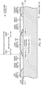
- FIGURE 1B illustrates an example longitudinal section 150 of physical object 100 of FIGURE 1A .
- Longitudinal section 150 of FIGURE 1B is cut through smooth surface 104 and a series of staggered periodic riblets 102.
- longitudinal section 150 is cut through first periodic riblet 110 and third periodic riblet 130.
- First periodic riblet 110 overlaps second periodic riblet 120 and third periodic riblet 130 overlaps second periodic riblet 120 and fourth periodic riblet 140.
- Each staggered periodic riblet 102 is located above plane 180 of smooth surface 104.
- Each staggered periodic riblet 102 (e.g., third periodic riblet 130) of FIGURE 1B includes transition region 145a and transition region 145b.
- Transition region 145a is located at a first end of each staggered periodic riblet 102 and transition region 145b is located at a second end of each staggered periodic riblet 102.
- Each staggered periodic riblet 102 of FIGURE 1B has a length L1.
- length L1 is less than 0.10 inches.
- length L1 may be between 0.04 inches and 0.08 inches.
- length L1 is 0.06 inches.
- Each transition region 145a and each transition region 145b of staggered periodic riblet 102 has a length L2.
- length L2 is less than 0.05 inches.
- length L2 may be between 0.01 inches and 0.02 inches.
- length L2 is 0.015 inches.
- Each peak of each staggered periodic riblet 102 has a length L3.
- length L3 is less than 0.06 inches.
- length L3 may be between 0.02 inches and 0.04 inches.
- length L1 is 0.03 inches.
- Length L1 of each staggered periodic riblet 102 equals the sum of length L2 of transition region 145a, length L3 of peak 106, and length L2 of transition region 145b.
- Length L1 of staggered periodic riblets 102 of physical object 100 runs parallel to a flow direction 155.
- physical object 100 may be a wing of an aircraft, and length L1 of staggered periodic riblets 102 of physical object 100 may run parallel to flow direction 155 generated by the aircraft when the aircraft is in flight.
- length L1 of each staggered periodic riblet 102 is within a range of 8 to 100 times longer than a maximum height of each respective staggered periodic riblet 102.
- transition regions 145a and 145b of each staggered periodic riblet 102 intersects smooth surface 104 such that an edge is created along smooth surface 104.
- Transition regions 145a and 145b may be constructed such that the sum of the increasing area in the longitudinal direction on transition region 145a is equal to the decreasing cross sectional area of transition region 145b.
- transition regions 145a an 145b are constructed with linear growth in the cross sectional area in the longitudinal direction for transition region 145a and linear decrease in the longitudinal direction in the cross sectional area of downstream transition region 145b. This construction maintains a constant longitudinal cross sectional area for overlapping transitional regions 145.
- each transition region 145 is defined by a parabolic shape.
- a leading edge of transition region 145a may be at an angle 170 of 90 degrees to smooth surface 104.
- the ridge of transition section 145a is convex to the external flow from flow direction 155 and meets peak 130 with an angular discontinuity.
- a trailing edge of transition region 145b may be at an angle 172 of 90 degrees to smooth surface 104.
- the cross sectional shape of transition regions 145 in the longitudinal direction may vary while maintaining the linear longitudinal change in the cross sectional area.
- the height of one or more transition regions 145 may be defined by a non-parabolic shape (e.g., a linear shape).
- FIGURE 2A illustrates an example cross section 200 of a protruding riblet pattern 210.
- Protruding riblet pattern 210 is a pattern of protruding riblets 212 that protrude above a plane of an adjacent surface.
- protruding riblets 212 would be located above the plane of smooth surface 104 of first periodic riblets 110 of physical object 100 such that each valley between adjacent protruding riblets 212 may be located along the plane of smooth surface 104 of first periodic riblets 110 of physical object 100.
- a physical object having a ribbed surface of protruding riblets 212 experiences less friction drag when subjected to dynamic (e.g., aerodynamic or hydrodynamic) flow than a comparable physical object having a smooth surface.
- dynamic e.g., aerodynamic or hydrodynamic
- a physical object having a ribbed surface of protruding riblets 212 experiences higher pressure drag when subjected to dynamic flow than a comparable physical object having a smooth surface.
- protruding riblet pattern 210 protrudes above baseline 220.
- Baseline 220 is equivalent to a plane of an adjacent surface (e.g., smooth surface 104 of FIGURE 1A ).
- Protruding riblet pattern 210 of FIGURE 2A is a sawtooth pattern.
- Each protruding riblet 212 of protruding riblet pattern 210 has a peak 214.
- Peak 214 of each protruding riblet 212 has a height relative to baseline 220 of less than 0.002 inches. In certain embodiments, the height of each peak 214 of each protruding riblet 212 may be within a range of 0.001 inches to 0.002 inches (e.g., 0.0018 inches).
- each peak 214 of each protruding riblet 212 forms an angle 230.
- Angle 230 may range from 45 degrees to 135 degrees. In the illustrated embodiment of FIGURE 2A , angle 230 is 90 degrees.
- each protruding riblet 212 may be a two-dimensional (2D), thin plate riblet that is perpendicular to and located above baseline 220 of cross section 200. The 2D, thin plate riblets may create a series of channels with thin blades defining the channel walls.
- Adjacent protruding riblets 212 of protruding riblet pattern 210 form valleys 216.
- Each valley 216 of each protruding riblet 212 is located at baseline 220.
- Each valley 216 forms an angle 240.
- Angle 240 may range from 45 degrees to 135 degrees. In the illustrated embodiment of FIGURE 2A , angle 240 is 90 degrees.
- one or more valleys 216 may be located above baseline 220.
- each valley 216 of each protruding riblet 212 may be located 0.0002 inches above baseline 220.
- Each base 244 of each protruding riblet 212 has a length less than 0.004 inches. In certain embodiments, the length of each base 244 of each protruding riblet 212 of protruding riblet pattern 210 is within a range of 0.003 inches to 0.004 inches (e.g., 0.0035 inches).
- cross section 200 of FIGURE 2A illustrates a particular number of protruding riblets 212, peaks 214, and valleys 216
- this disclosure contemplates any suitable number of protruding riblets 212, peaks 214, and valleys 216.
- protruding riblet pattern 210 of FIGURE 2A may include more or less than seven protruding riblets 212.
- cross section 200 of FIGURE 2A illustrates a particular arrangement of protruding riblets 212, peaks 214, and valleys 216, this disclosure contemplates any suitable arrangement of protruding riblets 212, peaks 214, and valleys 216.
- two or more protruding riblets 212 of FIGURE 2A may have different sizes, shapes, and/or orientations.
- two or more peaks 214 of two or more protruding riblets 212 may have different heights above baseline 220.
- one or more peaks 214 and/or valleys 216 of one or more protruding riblets 212 may have a rounded point.
- the length of sides 242 and base 244 may be the same to form equilateral triangles.
- the geometry of a ribbed surface of a physical object that uses protruding riblet pattern 210 increases the wetted area as compared to a smooth surface.
- a physical object with a protruding ribbed surface that uses protruding riblet pattern 210 experiences less friction drag when subjected to dynamic flow than a comparable physical object having a smooth surface, the pressure drag increases due to the increased projected area in the flow direction.
- staggered riblet pattern 260 While a physical object with a staggered ribbed surface that uses staggered riblet pattern 260 experiences higher pressure drag when subjected to dynamic flow than a comparable physical object having a smooth surface, the pressure drag created by staggered riblet pattern 260 is significantly less than the pressure drag created by protruding riblet pattern 210 of FIGURE 2A .
- staggered riblet pattern 260 is staggered above baseline 270.
- Baseline 270 is equivalent to a plane of a smooth surface (e.g., smooth surface 104 of FIGURE 1A ).
- Staggered riblet pattern 260 of FIGURE 2B is a variant of a sawtooth pattern with a space between each of the teeth.
- Each staggered riblet 262 of staggered riblet pattern 250 has a peak 264 located above baseline 270.
- Each peak 264 of each staggered riblet 262 has a height relative to baseline 270 of less than 0.002 inches.
- Each peak 264 forms an angle 280.
- Angle 280 may range from 45 degrees to 135 degrees. In the illustrated embodiment of FIGURE 2B , angle 280 is 90 degrees.
- Adjacent staggered riblets 262 of staggered riblet pattern 260 form valleys 266. Each valley 266 of each staggered riblet 262 is located along baseline 270. Each valley 266 of each staggered riblet 262 includes a space between staggered riblets 262 and forms an angle 290 at an intersection of each adjacent staggered riblet 262. Angle 290 may range from 45 degrees to 135 degrees. In the illustrated embodiment of FIGURE 2B , angle 290 is 90 degrees.
- Each staggered riblet 262 of staggered riblet pattern 260 of FIGURE 2B is in the shape of a triangle. Each staggered riblet 262 may be equal in size, shape, and/or orientation. Each staggered riblet 262 of staggered riblet pattern 260 has two sides 292 and a base 294. Each side 292 of each staggered riblet 262 has a length less than 0.004 inches. In certain embodiments, the length of each side 292 of each staggered riblet 262 of staggered riblet pattern 260 is within a range of 0.002 inches to 0.003 inches (e.g., 0.0025 inches).
- Each base 294 of each staggered riblet 262 has a length less than 0.004 inches. In certain embodiments, the length of each base 294 of each staggered riblet 262 of staggered riblet pattern 260 is within a range of 0.003 inches to 0.004 inches (e.g., 0.0035 inches). In the illustrated embodiment of FIGURE 2B , the space along each valley 266 between adjacent staggered riblets 262 is equal in length to the length of base 294.
- staggered riblets 262 depends on the application of staggered riblet pattern 260.
- the size of each staggered riblet 262 may depend on the speed of fluid, the viscosity and/or density of the fluid, the scale of the object (e.g., physical object 100 of FIGURE 1A ), etc.
- staggered riblets 262 are less than a hundredth of an inch in depth.
- staggered riblets 262 may be greater than a hundredth of an inch in depth.
- staggered riblets 262 may be sized using turbulent wall scaling.
- cross section 250 of FIGURE 2B illustrates a particular number of staggered riblets 262, peaks 264, and valleys 266, this disclosure contemplates any suitable number of staggered riblets 262, peaks 264, and valleys 266.
- staggered riblet pattern 260 of FIGURE 2B may include more or less than four staggered riblets 262.
- cross section 250 of FIGURE 2B illustrates a particular arrangement of staggered riblets 262, peaks 264, and valleys 266, this disclosure contemplates any suitable arrangement of staggered riblets 262, peaks 264, and valleys 266.
- two or more staggered riblets 262 of FIGURE 2B may have different sizes, shapes, and/or orientations.
- two or more peaks 262 may have different heights relative to baseline 270.
- the length of sides 292 and base 294 of one or more staggered riblets 262 may be the same to form equilateral triangles.
- Structure 310 of pressure pattern 300 includes smooth surfaces 320 similar to smooth surface 104 of FIGURE 1A .
- Structure 310 of pressure pattern 300 includes protruding ribbed surfaces 330 that protrude above the plane of smooth surfaces 320.
- Protruding ribbed surfaces 330 form protruding riblet pattern 340.
- protruding riblet pattern 340 is a sawtooth pattern similar to protruding riblet pattern 210 of FIGURE 2A .
- the lowest Cp value i.e., -0.040
- the highest Cp value i.e., 0.040
- the grayscale lightens in shade as the Cp value increases.
- FIGURE 3B illustrates an example pressure pattern 350 associated with a staggered riblet pattern 390 (e.g., staggered riblet pattern 260 of FIGURE 2B ).
- Pressure pattern 350 was created using the same simulation technique of FIGURE 3A .
- the flow direction 355 is parallel to the staggered riblets of staggered riblet pattern 390.
- the output of the simulation is displayed in FIGURE 3B as pressure pattern 350.
- staggered riblet pattern 390 produces a small variant of Cp values ranging from 0 to 0.008. Positive Cp values are generated along staggered riblet pattern 390. The highest Cp values are generated in transition regions 394 as the flow travels in flow direction 355 from smooth surface 370 to each staggered riblet 380. As such, staggered riblet pattern 390 shown in FIGURE 3B mitigates the pressure differentials shown in pressure pattern 300 of FIGURE 3A by producing almost constant pressures over the surfaces of structure 360.
- Bar chart 400 includes drag differences for a protruding riblet pattern 410 and a staggered riblet pattern 420.
- Protruding riblet pattern 410 is equivalent to protruding riblet pattern 210 of FIGURE 2A .
- Staggered riblet pattern 410 is equivalent to staggered riblet pattern 260 of FIGURE 2B .
- the drag for protruding riblet pattern 410 and staggered riblet pattern 420 is measured as a percentage difference from the drag generated by a smooth surface without riblets. Pressure drag differences, friction (e.g., viscous) drag differences, and total drag differences are provided in bar chart 400.
- Staggered riblet pattern 420 as illustrated in bar chart 400 of FIGURE 4 , generates a percent pressure drag difference 422 of positive 0.8 percent, which indicates that staggered riblet pattern 420 generates a pressure drag that is 0.8 percent greater than the pressure drag generated by a smooth surface.
- Staggered riblet pattern 420 generates a percent viscous drag difference 424 of negative six percent, which indicates that staggered riblet pattern 420 generates a viscous drag that is six percent lower than the viscous drag generated by a smooth surface.
- the total drag difference which is calculated by adding pressure drag difference 422 and viscous drag difference 424 of staggered riblet pattern 420, is negative 5.2 percent, which indicates that staggered riblet pattern 420 generates a total drag that is 5.2 percent lower than the total drag generated by a smooth surface.
- staggered riblet pattern 420 is effective at reducing viscous drag as compared to a smooth surface without riblets and is also effective at reducing the overall drag when taking into consideration both viscous drag and pressure drag.
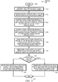
- FIGURE 5 illustrates an example method 500 for reducing drag on a surface having a staggered riblet pattern, in accordance with an example embodiment.
- Method 500 starts at step 505.
- first periodic riblets e.g., first periodic riblets 110 of FIGURE 1
- a smooth surface e.g., smooth surface 104 of FIGURE 1A
- a physical object e.g., physical object 100 of FIGURE 1A .
- Method 500 then moves from step 515 to step 520, where a first transition region (e.g., transition region 145a of FIGURE 1B ) is formed at a first end (e.g., first end 112 of FIGURE 1A ) of each first periodic riblet and a second transition region (e.g., transition region 145b of FIGURE 1B ) is formed at a second end (e.g., second end 114 of FIGURE 1A ) of each first periodic riblet.
- the transition regions may be approximately the same length.
- An angle between a surface of each transition region and the smooth surface may be the same. For example, each angle between the surface of each transition region and the smooth surface of each staggered periodic riblet may be approximately 170 degrees.
- Method 500 moves from step 520 to step 525.
- a first transition region is formed at a first end of each second periodic riblet and a second transition region is formed at a second end of each second periodic riblet.
- Method 500 then moves from step 525 to step 530.
- a flow is generated over the smooth surface and the first and second periodic riblets of the physical object.
- the flow may be generated by an airplane moving through the air at a predetermined speed.
- the flow direction e.g., flow diction 335 of FIGURE 3B
- Method 500 then moves from step 535 to step 540, where method 500 determines whether the flow is a gas or a liquid.
- step 550 a hydrodynamic drag is generated over the staggered riblet pattern that is less than the total hydrodynamic drag (i.e., pressure drag and viscous drag) produced by generating a flow over a smooth surface without riblets.
- the hydrodynamic drag generated over the staggered riblet pattern that is less than the total hydrodynamic drag produced by generating a flow over a protruding riblet pattern e.g., protruding riblet pattern 410 of FIGURE 4 ).
- the staggered riblet pattern reduces drag over hydrodynamic surfaces, which may reduce fuel costs and increase range in vehicles (e.g., marine vessels) utilizing the staggered riblet pattern.
- Method 500 then moves from steps 545 and 550 to step 555, where method 500 ends.
- FIGURE 6 illustrates an example physical object 600 with staggered periodic riblets 702 having a different size and shape than staggered periodic riblets 102 of FIGURE 1A .
- Physical object 600 is similar to physical object 100 except as follows.
- a cross section of each staggered periodic riblet 602 of FIGURE 6 forms an equilateral triangle such that a length of each base (e.g., base 294 of FIGURE 2B ) of each staggered periodic riblet 602 is the same as a length of each side (e.g., sides 292 of FIGURE 2B ) of each staggered periodic riblet 602.
- each peak 606 of each staggered periodic riblet 602 above a plane (e.g., plane 180 of FIGURE 1B ) of smooth surface 604 is less than the height of each peak 106 of each staggered periodic riblet 102 of FIGURE 1A .
- the height of each peak 606 of each staggered periodic riblet 602 above a plane of smooth surface 604 may be less than 0.0018 inches (e.g., 0.0015 inches.)
- Transition regions 645 of FIGURE 6 are regions staggered periodic riblets 602 overlap.
- FIGURE 7 illustrates an example physical object 700 with staggered periodic riblets 702 having a different size, shape, and arrangement than staggered periodic riblets 102 of FIGURE 1A .
- Physical object 700 is similar to physical object 100 of FIGURE 1A except as follows.
- a cross section of each staggered periodic riblet 702 of FIGURE 7 forms an equilateral triangle such that a length of each base (e.g., base 294 of FIGURE 2B ) of each staggered periodic riblet 702 is the same as a length of each side (e.g., sides 292 of FIGURE 2B ) of each staggered periodic riblet 702.
- each peak 706 of each staggered periodic riblet 702 above a plane (e.g., plane 180 of FIGURE 1B ) of smooth surface 704 is greater than the height of each peak 106 of each staggered periodic riblet 102 of FIGURE 1A .
- the height of each peak 706 of each staggered periodic riblet 702 above a plane of smooth surface 704 may be greater than 0.0018 inches (e.g., 0.002 inches.)
- FIGURES 6 and 7 illustrate a particular number of staggered periodic riblets 602 and 702, smooth surfaces 604 and 704, peaks 606 and 706, valleys 608 and 708, and transition regions 645 and 745
- this disclosure contemplates any suitable number of staggered periodic riblets 602 and 702, smooth surfaces 604 and 704, peaks 606 and 706, valleys 608 and 708, and transition regions 645 and 745.
- staggered periodic riblets 702 may be spaced further apart or closer together.
- staggered periodic riblets 702 may be continuous along a length of physical object 700 such that an end of a first staggered periodic riblet 702 touches an end of a second staggered periodic riblet 702.
- Embodiments of this disclosure may be applied to any fluid flow application where the turbulent boundary layer is turbulent and skin friction is significant.
- embodiments of this disclosure may be used to reduce internal flow drag in propulsion systems, reduce pipe flow drag, reduce drag in automotive systems, and the like.
- references in the appended claims to an apparatus or system or a component of an apparatus or system being adapted to, arranged to, capable of, configured to, enabled to, operable to, or operative to perform a particular function encompasses that apparatus, system, component, whether or not it or that particular function is activated, turned on, or unlocked, as long as that apparatus, system, or component is so adapted, arranged, capable, configured, enabled, operable, or operative. Additionally, although this disclosure describes or illustrates particular embodiments as providing particular advantages, particular embodiments may provide none, some, or all of these advantages
Landscapes
- Engineering & Computer Science (AREA)
- Physics & Mathematics (AREA)
- Fluid Mechanics (AREA)
- Mechanical Engineering (AREA)
- General Engineering & Computer Science (AREA)
- Aviation & Aerospace Engineering (AREA)
- Extrusion Moulding Of Plastics Or The Like (AREA)
- Non-Portable Lighting Devices Or Systems Thereof (AREA)
Abstract
Description
- This disclosure generally relates to riblets, and more specifically to staggered periodic riblets.
- An object (e.g., an aircraft or a marine vessel) that moves through a fluid (e.g., air or water) experiences a drag force. An increase in the drag force experienced by the object increases the energy required for the object to move through the fluid. For example, an increase in the drag force experienced by an aircraft moving at an established speed may increase the power required by the aircraft to move through the air at the same established speed. Thus, drag force has a significant impact of aircraft fuel consumption and aircraft range.
- According to an embodiment, a method for reducing drag includes forming first periodic riblets on a smooth surface of a physical object and forming second periodic riblets on the smooth surface of the physical object. The method further includes generating a flow over the first and second periodic riblets of the physical object. Each first periodic riblet comprises a first transition region at a first end of each first periodic riblet and a second transition region at a second end of each first periodic riblet. Each second periodic riblet comprises a first transition region at a first end of each second periodic riblet and a second transition region at a second end of each second periodic riblet. Each second transition region at the second end of each first periodic riblet overlaps each first transition region at the first end of each second periodic riblet. A length of each riblet of the first and second periodic riblets runs parallel to a direction of the flow.
- According to another embodiment, a physical object includes a smooth surface, first periodic riblets on the smooth surface of a physical object, and second periodic riblets on the smooth surface of the physical object. Each first periodic riblet comprises a first transition region at a first end of each first periodic riblet and a second transition region at a second end of each first periodic riblet. Each second periodic riblet comprises a first transition region at a first end of each second periodic riblet and a second transition region at a second end of each second periodic riblet. Each second transition region at the second end of each first periodic riblet overlaps each first transition region at the first end of each second periodic riblet.
- According to yet to another embodiment, a method of manufacturing a physical object includes forming first periodic riblets on a smooth surface of a physical object. The method further includes forming second periodic riblets on the smooth surface of the physical object. Each first periodic riblet comprises a first transition region at a first end of each first periodic riblet and a second transition region at a second end of each first periodic riblet. Each second periodic riblet comprises a first transition region at a first end of each second periodic riblet and a second transition region at a second end of each second periodic riblet. Each second transition region at the second end of each first periodic riblet overlaps each first transition region at the first end of each second periodic riblet.
- Technical advantages of this disclosure may include one or more of the following. The use of staggered periodic riblets on physical objects reduces overall drag, which includes pressure and viscous drag, experienced by the physical object as compared to physical objects having a smooth surface, which may significantly reduce fuel costs since less power is required to move the object through the fluid (e.g., gas or liquid). The drag reduction experienced by physical objects such as aircraft that use staggered periodic riblets may also increase the range (i.e., the maximum distance the aircraft can fly between takeoff and landing) of the physical object as compared to physical objects that have a smooth surface. In certain embodiments, the drag reduction may allow higher maximum speeds to be obtained for a fixed propulsion input.
- In some embodiments, staggered periodic riblets may reduce heat transfer on a hot or cold surface adjacent to a turbulent boundary layer, which may reduce the insulation required in particular applications. The use of staggered periodic riblets may delay or prevent the separation of the flow in a turbulent boundary layer from the surface, which may reduce aerodynamic drag, increase lift on a physical object (e.g., an aircraft wing), and/or improve the performance of propulsion systems.
- Other technical advantages will be readily apparent to one skilled in the art from the following figures, descriptions, and claims. Moreover, while specific advantages have been enumerated above, various embodiments may include all, some, or none of the enumerated advantages.
- To assist in understanding the present disclosure, reference is now made to the following description taken in conjunction with the accompanying drawings, in which:
-
FIGURE 1A illustrates a physical object with staggered periodic riblets, in accordance with an example embodiment; -
FIGURE 1B illustrates a cross section of the physical object ofFIGURE 1A , in accordance with an example embodiment; -
FIGURE 2A illustrates a cross section of a protruding riblet pattern, in accordance with an example embodiment; -
FIGURE 2B illustrates a cross section of a staggered riblet pattern, in accordance with an example embodiment; -
FIGURE 3A illustrates a pressure output pattern associated with a physical object having a protruding riblet pattern, in accordance with an example embodiment; -
FIGURE 3B illustrates a pressure output pattern associated with a physical object having a staggered riblet pattern, in accordance with an example embodiment; -
FIGURE 4 illustrates a bar chart that compares drag produced by a physical object having a protruding riblet pattern to a physical object having a staggered riblet pattern, in accordance with an example embodiment; -
FIGURE 5 illustrates an example method for reducing drag on a surface using a staggered riblet pattern, in accordance with an example embodiment; -
FIGURE 6 illustrates a physical object with staggered periodic riblets having a different size and shape than the staggered periodic riblets ofFIGURE 1A , in accordance with an example embodiment; and -
FIGURE 7 illustrates a physical object with staggered periodic riblets having a different size, shape, and arrangement than the staggered periodic riblets ofFIGURE 1A , in accordance with an example embodiment. - Embodiments of this disclosure describe physical objects having staggered periodic riblets that may be used to reduce drag, which includes pressure drag and friction drag, over the surfaces of the physical objects. Riblets are very small (e.g., less than a hundredth of an inch in depth) grooves or channels on a surface of a physical object (e.g., a vehicle). The riblets run parallel to the direction of flow. Staggered periodic riblets are riblets with overlapping regions. Staggered periodic riblets are located above a smooth surface of the physical object.
- Certain three-dimensional (3D) riblet structures may reduce skin friction drag due to reduced wetted area. However, these 3D riblet structures may generate additional pressure drag due to the added frontal area of the surface feature. The staggered periodic riblets described herein increase the drag reducing benefits of riblets by significantly reducing or eliminating the pressure drag penalty as compared to certain other 3D riblet structures. Staggered periodic riblets may maintain a constant cross sectional area in the streamwise flow direction. The constant cross sectional area is achieved by compensating the decreasing volume of the trailing edge of each staggered periodic riblet with the increasing volume of the neighboring staggered periodic riblets. As such, embodiments of this disclosure use staggered periodic riblets to reduce and/or eliminate the pressure drag penalty as compared to certain other periodic riblets.
-
FIGURES 1 through 5 show example apparatuses and methods associated with staggered periodic riblets.FIGURE 1A shows an example physical object with staggered periodic riblets andFIGURE 1B shows an example longitudinal section of the physical object ofFIGURE 1A .FIGURE 2A shows an example cross section of a protruding riblet pattern andFIGURE 2B shows an example cross section of a staggered riblet pattern.FIGURE 3A shows an example pressure output pattern associated with a physical object having a protruding riblet pattern andFIGURE 3B shows an example pressure output pattern associated with a physical object having a staggered riblet pattern.FIGURE 4 shows an example bar chart that compares drag produced by a physical object having a protruding riblet pattern to a physical object having a staggered riblet pattern.FIGURE 5 shows an example method for reducing drag on a surface using a staggered riblet pattern.FIGURE 6 shows a physical object with staggered periodic riblets having a different size and shape than the staggered periodic riblets ofFIGURE 1A , andFIGURE 7 shows a physical object with staggered periodic riblets having a different size, shape, and arrangement than the staggered periodic riblets ofFIGURE 1A . -
FIGURE 1A illustrates an examplephysical object 100 having staggeredperiodic riblets 102.Physical object 100 with staggeredperiodic riblets 102 may be used to reduce overall drag (e.g., aerodynamic or hydrodynamic drag) over a surface as compared to aphysical object 100 without staggeredperiodic riblets 102. One or more portions ofphysical object 100 may be made of steel, aluminum, copper, titanium, nickel, plastic, fiberglass, a combination thereof, or any other suitable material. -
Physical object 100 is any object that is susceptible to drag (e.g., skin friction drag and pressure drag.) For example,physical object 100 may be a component (e.g., a portion of an outer body) of an aircraft (e.g., an airplane, a helicopter, a blimp, a drone, etc.), a component of a marine vessel (e.g., a cargo ship, a passenger ship, a canoe, a raft, etc.), a component of a motorized vehicle (e.g., a truck, a car, a a train, a scooter, etc.), a component of a non-motorized vehicle (e.g., a bicycle, a skateboard, etc.), a component of a spacecraft (e.g., a spaceship, a satellite, etc.), a wind turbine, a projectile (e.g., a missile), or any other physical object that is capable of experiencing drag. In certain embodiments, drag may be generated by a force acting opposite to the relative motion of physical object 100 (e.g., a wing of an aircraft) moving with respect to a surrounding fluid (e.g., air). In some embodiments, drag is generated by the viscosity of gas. In certain embodiments, drag may be generated due to the viscosity of a fluid (e.g., water) near the surface of physical object 100 (e.g., a section of a pipe or duct.) -
Physical object 100 includes asmooth surface 104. In certain embodiments,smooth surface 104 ofphysical object 100 is flat. In some embodiments,smooth surface 104 ofphysical object 100 may have a curvature. Staggeredperiodic riblets 102 ofphysical object 100 may be formed onsmooth surface 104. Staggeredperiodic riblets 102 ofphysical object 100 are staggered such that each staggeredperiodic riblet 102 overlaps at least one other staggeredperiodic riblet 102 in plan view. Each staggeredperiodic riblet 102 is located above a plane (e.g.,plane 180 ofFIGURE 1B ) ofsmooth surface 104 ofphysical object 100. In certain embodiments, a cross sectional area as measured abovesmooth surface 104 ofphysical object 100 is approximately (i.e., within five percent) the same at any cross section through staggeredperiodic riblets 102. - Each staggered
periodic riblet 102 includes apeak 106. Eachpeak 106 of each staggeredperiodic riblet 102 is a point along an exterior surface of staggeredperiodic riblet 102 that is farthest away from the plane ofsmooth surface 104 in a direction away fromphysical object 100. In the illustrated embodiment ofFIGURE 1A , peaks 106 of staggeredperiodic riblets 102 extend a predetermined distance (e.g., 0.002 inches) above the plane ofsmooth surface 104 ofphysical object 100. In some embodiments, one ormore peaks 106 of one or more staggeredperiodic riblets 102 may form a pointed tip. In some embodiments, one ormore peaks 106 of one or more staggeredperiodic riblets 102 may form a flat or rounded peak surface. The spaces between adjacent staggeredperiodic riblets 102 createvalleys 108. Eachvalley 108 between adjacent staggeredperiodic riblets 102 is an area along an exterior surface of staggeredperiodic riblet 102 that is closest to the plane ofsmooth surface 104. In the illustrated embodiment ofFIGURE 1A ,valleys 108 of staggeredperiodic riblets 102 are located along the plane ofsmooth surface 104 ofphysical object 100. - Each staggered
periodic riblet 102 includes twotransition regions 145. Afirst transition region 145 is located at a first end of each staggeredperiodic riblet 102 and asecond transition region 145 is located at a second end of each staggeredperiodic riblet 102. Eachtransition region 145 of each staggeredperiodic riblet 102 slopes down frompeak 106 tosmooth surface 104. In certain embodiments, eachtransition region 145 decreases in height and width as each respective staggeredperiodic riblet 102 slopes down frompeak 106 tosmooth surface 104. For example, the height and/or width of eachtransition region 145 may decrease (e.g., linearly decrease) until the height and/or width equals zero. The slope of eachtransition region 145 may be linear or parabolic.Transition regions 145 are discussed in more detail inFIGURE 1B below. Each staggeredperiodic riblet 102 may be approximately the same in size, shape, and/or orientation. - Staggered
periodic riblets 102 ofFIGURE 1A include firstperiodic riblets 110, secondperiodic riblets 120, thirdperiodic riblets 130, and fourthperiodic riblets 140. Each firstperiodic riblet 110 includes afirst end 112 and asecond end 114. Each secondperiodic riblet 120 includes afirst end 122 and a second end 124. Each thirdperiodic riblet 130 includes afirst end 132 and asecond end 134. Each fourthperiodic riblet 140 includes afirst end 142 and a second end 144. - First
periodic riblets 110 ofphysical object 100 are parallel to one another. In certain embodiments, a distance between each peak 106 of each firstperiodic riblet 110 is approximately the same.Transition region 145 at eachsecond end 114 of each firstperiodic riblet 110overlaps transition region 145 at each first end 124 of each secondperiodic riblet 120. Secondperiodic riblets 120 ofphysical object 100 are parallel to one another. In certain embodiments, a distance between each peak 106 of each secondperiodic riblet 120 is approximately the same.Transition region 145 at each second end 124 of each secondperiodic riblet 210overlaps transition region 145 at eachfirst end 132 of each thirdperiodic riblet 130. - Third
periodic riblets 130 ofphysical object 100 are parallel to one another. In certain embodiments, a distance between each peak 106 of each thirdperiodic riblet 130 is approximately the same.Transition region 145 at eachsecond end 134 of each thirdperiodic riblet 110overlaps transition region 145 at eachfirst end 142 of each fourthperiodic riblet 140. Fourthperiodic riblets 140 ofphysical object 100 are parallel to one another. In certain embodiments, a distance between each peak 106 of each fourthperiodic riblet 140 is approximately the same. - While the lengths of first
periodic riblets 110, secondperiodic riblets 120, thirdperiodic riblets 130, and fourthperiodic riblets 140 are approximately (e.g., within five percent) the same in the illustrated embodiment ofFIGURE 1A , the length of each firstperiodic riblet 110, secondperiodic riblet 120, thirdperiodic riblet 130, and fourthperiodic riblet 140 may be any suitable length. For example, one or more lengths of firstperiodic riblets 110, secondperiodic riblets 120, thirdperiodic riblets 130, and fourthperiodic riblets 140 may vary by a factor of two. - Although
physical object 100 ofFIGURE 1A illustrates a particular number of staggered periodic riblets 102 (e.g., firstperiodic riblets 110, secondperiodic riblets 120, thirdperiodic riblets 130, and fourth periodic riblets 140),smooth surfaces 104,peaks 106,valleys 108, andtransition regions 145, this disclosure contemplates any suitable number of staggeredperiodic riblets 102,smooth surfaces 104,peaks 106,valleys 108, andtransition regions 145. For example,physical object 100 ofFIGURE 1A may include fifth staggered periodic riblets, sixth staggered periodic riblets, and so on. - Although
physical object 100 ofFIGURE 1A illustrates a particular arrangement of staggered periodic riblets 102 (e.g., firstperiodic riblets 110, secondperiodic riblets 120, thirdperiodic riblets 130, and fourth periodic riblets 140),smooth surfaces 104,peaks 106,valleys 108, andtransition regions 145, this disclosure contemplates any suitable arrangement of staggered periodic riblets 102 (e.g., firstperiodic riblets 110, secondperiodic riblets 120, thirdperiodic riblets 130, and fourth periodic riblets 140),smooth surfaces 104,peaks 106,valleys 108, andtransition regions 145. For example, staggeredperiodic riblets 102 may be spaced further apart or closer together. -
FIGURE 1B illustrates an examplelongitudinal section 150 ofphysical object 100 ofFIGURE 1A .Longitudinal section 150 ofFIGURE 1B is cut throughsmooth surface 104 and a series of staggeredperiodic riblets 102. In the illustrated embodiment ofFIGURE 1B ,longitudinal section 150 is cut through firstperiodic riblet 110 and thirdperiodic riblet 130. Firstperiodic riblet 110 overlaps secondperiodic riblet 120 and thirdperiodic riblet 130 overlaps secondperiodic riblet 120 and fourthperiodic riblet 140. Each staggeredperiodic riblet 102 is located aboveplane 180 ofsmooth surface 104. Each staggered periodic riblet 102 (e.g., third periodic riblet 130) ofFIGURE 1B includestransition region 145a andtransition region 145b.Transition region 145a is located at a first end of each staggeredperiodic riblet 102 andtransition region 145b is located at a second end of each staggeredperiodic riblet 102. - Each staggered
periodic riblet 102 ofFIGURE 1B has a length L1. In certain embodiments, length L1 is less than 0.10 inches. For example, length L1 may be between 0.04 inches and 0.08 inches. In the illustrated embodiment ofFIGURE 1B , length L1 is 0.06 inches. Eachtransition region 145a and eachtransition region 145b of staggeredperiodic riblet 102 has a length L2. In certain embodiments, length L2 is less than 0.05 inches. For example, length L2 may be between 0.01 inches and 0.02 inches. In the illustrated embodiment ofFIGURE 1B , length L2 is 0.015 inches. Each peak of each staggeredperiodic riblet 102 has a length L3. In certain embodiments, length L3 is less than 0.06 inches. For example, length L3 may be between 0.02 inches and 0.04 inches. - In the illustrated embodiment of
FIGURE 1B , length L1 is 0.03 inches. Length L1 of each staggeredperiodic riblet 102 equals the sum of length L2 oftransition region 145a, length L3 ofpeak 106, and length L2 oftransition region 145b. Length L1 of staggeredperiodic riblets 102 ofphysical object 100 runs parallel to aflow direction 155. For example,physical object 100 may be a wing of an aircraft, and length L1 of staggeredperiodic riblets 102 ofphysical object 100 may run parallel to flowdirection 155 generated by the aircraft when the aircraft is in flight. In certain embodiments, length L1 of each staggeredperiodic riblet 102 is within a range of 8 to 100 times longer than a maximum height of each respective staggeredperiodic riblet 102. - The surface of each
transition region 145a and eachtransition region 145b of each staggeredperiodic riblet 102 intersectssmooth surface 104 such that an edge is created alongsmooth surface 104.Transition regions transition region 145a is equal to the decreasing cross sectional area oftransition region 145b. In certain embodiments,transition regions 145a an 145b are constructed with linear growth in the cross sectional area in the longitudinal direction fortransition region 145a and linear decrease in the longitudinal direction in the cross sectional area ofdownstream transition region 145b. This construction maintains a constant longitudinal cross sectional area for overlappingtransitional regions 145. - In certain embodiments, for
transitional regions 145 having a geometrically similar cross section in the longitudinal direction, the height of eachtransition region 145 is defined by a parabolic shape. A leading edge oftransition region 145a may be at anangle 170 of 90 degrees tosmooth surface 104. The ridge oftransition section 145a is convex to the external flow fromflow direction 155 and meetspeak 130 with an angular discontinuity. A trailing edge oftransition region 145b may be at anangle 172 of 90 degrees tosmooth surface 104. In some embodiments, the cross sectional shape oftransition regions 145 in the longitudinal direction may vary while maintaining the linear longitudinal change in the cross sectional area. In certain embodiments, the height of one ormore transition regions 145 may be defined by a non-parabolic shape (e.g., a linear shape). -
Transition region 145b at the second end of each firstperiodic riblet 110overlaps transition region 145a at the first end of each secondperiodic riblet 120.Transition region 145b at the second end of each secondperiodic riblet 120overlaps transition region 145a at the first end of each thirdperiodic riblet 130.Transition region 145b at the second end of each thirdperiodic riblet 130overlaps transition region 145a at the first end of each fourthperiodic riblet 140. In certain embodiments, the intermittent pattern created by firstperiodic riblets 110, secondperiodic riblets 120, thirdperiodic riblets 130, and fourthperiodic riblets 140 repeats along a predetermined length. For example, this intermittent pattern may repeat along the width of an airplane wing. -
Staggered riblets 102 are staggered such that a cross sectional area as measured abovesmooth surface 104 ofphysical object 100 is approximately the same at any cross section throughlongitudinal section 150. For example, the total cross sectional area of a cross section taken throughpeak 130 of third periodic riblet 130 (which includes the cross sectional areas of a plurality of third periodic riblets 130) is approximately the same as the total cross sectional area of a cross section taken throughtransition region 145a of third periodic riblet 130 (which includes the cross sectional areas of a plurality of secondperiodic riblets 120 and a plurality of thirdperiodic riblets 130.) Maintaining a constant cross-sectional area of staggeredperiodic riblets 102 inflow direction 155 reduces the pressure drag penalty as compared to other riblet patterns, as illustrated inFIGURE 3A ,FIGURE 3B , andFIGURE 4 below. -
FIGURE 2A illustrates anexample cross section 200 of a protrudingriblet pattern 210. Protrudingriblet pattern 210 is a pattern of protruding riblets 212 that protrude above a plane of an adjacent surface. For example, referring to the illustrated embodiment ofFIGURE 1A , protruding riblets 212 would be located above the plane ofsmooth surface 104 of firstperiodic riblets 110 ofphysical object 100 such that each valley between adjacent protruding riblets 212 may be located along the plane ofsmooth surface 104 of firstperiodic riblets 110 ofphysical object 100. A physical object having a ribbed surface of protruding riblets 212 experiences less friction drag when subjected to dynamic (e.g., aerodynamic or hydrodynamic) flow than a comparable physical object having a smooth surface. However, due to the geometry of protrudingriblet pattern 210, a physical object having a ribbed surface of protruding riblets 212 experiences higher pressure drag when subjected to dynamic flow than a comparable physical object having a smooth surface. - In the illustrated embodiment of
FIGURE 2A , protrudingriblet pattern 210 protrudes abovebaseline 220.Baseline 220 is equivalent to a plane of an adjacent surface (e.g.,smooth surface 104 ofFIGURE 1A ). Protrudingriblet pattern 210 ofFIGURE 2A is a sawtooth pattern. Each protruding riblet 212 of protrudingriblet pattern 210 has apeak 214. Peak 214 of each protruding riblet 212 has a height relative tobaseline 220 of less than 0.002 inches. In certain embodiments, the height of eachpeak 214 of each protruding riblet 212 may be within a range of 0.001 inches to 0.002 inches (e.g., 0.0018 inches). Eachpeak 214 of each protruding riblet 212 forms anangle 230.Angle 230 may range from 45 degrees to 135 degrees. In the illustrated embodiment ofFIGURE 2A ,angle 230 is 90 degrees. In certain embodiments, each protruding riblet 212 may be a two-dimensional (2D), thin plate riblet that is perpendicular to and located abovebaseline 220 ofcross section 200. The 2D, thin plate riblets may create a series of channels with thin blades defining the channel walls. - Adjacent protruding riblets 212 of protruding
riblet pattern 210form valleys 216. Eachvalley 216 of each protruding riblet 212 is located atbaseline 220. Eachvalley 216 forms anangle 240.Angle 240 may range from 45 degrees to 135 degrees. In the illustrated embodiment ofFIGURE 2A ,angle 240 is 90 degrees. In some embodiments, one ormore valleys 216 may be located abovebaseline 220. For example, eachvalley 216 of each protruding riblet 212 may be located 0.0002 inches abovebaseline 220. - Each protruding riblet 212 of protruding
riblet pattern 210 ofFIGURE 2A is in the shape of a triangle. Each protruding riblet 212 may be equal in size, shape, and/or orientation relative tobaseline 220. In the illustrated embodiment ofFIGURE 2A , each protruding riblet 212 of protrudingriblet pattern 210 has twosides 242 and abase 244. Eachside 242 of each protruding riblet 212 has a length less than 0.004 inches. In certain embodiments, the length of eachside 242 of each protruding riblet 212 of protrudingriblet pattern 210 is within a range of 0.002 inches to 0.003 inches (e.g., 0.0025 inches). Eachbase 244 of each protruding riblet 212 has a length less than 0.004 inches. In certain embodiments, the length of each base 244 of each protruding riblet 212 of protrudingriblet pattern 210 is within a range of 0.003 inches to 0.004 inches (e.g., 0.0035 inches). - Although
cross section 200 ofFIGURE 2A illustrates a particular number of protruding riblets 212,peaks 214, andvalleys 216, this disclosure contemplates any suitable number of protruding riblets 212,peaks 214, andvalleys 216. For example, protrudingriblet pattern 210 ofFIGURE 2A may include more or less than seven protruding riblets 212. Althoughcross section 200 ofFIGURE 2A illustrates a particular arrangement of protruding riblets 212,peaks 214, andvalleys 216, this disclosure contemplates any suitable arrangement of protruding riblets 212,peaks 214, andvalleys 216. For example, two or more protruding riblets 212 ofFIGURE 2A may have different sizes, shapes, and/or orientations. As another example, two ormore peaks 214 of two or more protruding riblets 212 may have different heights abovebaseline 220. As still another example, one ormore peaks 214 and/orvalleys 216 of one or more protruding riblets 212 may have a rounded point. As yet another example, the length ofsides 242 andbase 244 may be the same to form equilateral triangles. - As illustrated in
cross section 200 ofFIGURE 2A , the geometry of a ribbed surface of a physical object that uses protrudingriblet pattern 210 increases the wetted area as compared to a smooth surface. As such, while a physical object with a protruding ribbed surface that uses protrudingriblet pattern 210 experiences less friction drag when subjected to dynamic flow than a comparable physical object having a smooth surface, the pressure drag increases due to the increased projected area in the flow direction. -
FIGURE 2B illustrates anexample cross section 250 of a staggeredriblet pattern 260. Staggeredriblet pattern 260 is a pattern of repeating staggered riblets that are located above a plane of a smooth surface. For example, staggered periodic riblets 262 may be equivalent to staggeredperiodic riblets 102 ofFIGURE 1A , which are located above the plane ofsmooth surface 104 ofphysical object 100. A physical object with a staggered ribbed surface that usesstaggered riblet pattern 260 experiences less friction drag when subjected to dynamic flow than a comparable physical object having a smooth surface. While a physical object with a staggered ribbed surface that usesstaggered riblet pattern 260 experiences higher pressure drag when subjected to dynamic flow than a comparable physical object having a smooth surface, the pressure drag created by staggeredriblet pattern 260 is significantly less than the pressure drag created by protrudingriblet pattern 210 ofFIGURE 2A . - In the illustrated embodiment of
FIGURE 2B , staggeredriblet pattern 260 is staggered abovebaseline 270.Baseline 270 is equivalent to a plane of a smooth surface (e.g.,smooth surface 104 ofFIGURE 1A ). Staggeredriblet pattern 260 ofFIGURE 2B is a variant of a sawtooth pattern with a space between each of the teeth. Each staggered riblet 262 of staggeredriblet pattern 250 has a peak 264 located abovebaseline 270. Eachpeak 264 of each staggered riblet 262 has a height relative tobaseline 270 of less than 0.002 inches. Each peak 264 forms anangle 280.Angle 280 may range from 45 degrees to 135 degrees. In the illustrated embodiment ofFIGURE 2B ,angle 280 is 90 degrees. - Adjacent staggered riblets 262 of staggered
riblet pattern 260form valleys 266. Eachvalley 266 of each staggered riblet 262 is located alongbaseline 270. Eachvalley 266 of each staggered riblet 262 includes a space between staggered riblets 262 and forms anangle 290 at an intersection of each adjacent staggered riblet 262.Angle 290 may range from 45 degrees to 135 degrees. In the illustrated embodiment ofFIGURE 2B ,angle 290 is 90 degrees. - Each staggered riblet 262 of staggered
riblet pattern 260 ofFIGURE 2B is in the shape of a triangle. Each staggered riblet 262 may be equal in size, shape, and/or orientation. Each staggered riblet 262 of staggeredriblet pattern 260 has twosides 292 and abase 294. Eachside 292 of each staggered riblet 262 has a length less than 0.004 inches. In certain embodiments, the length of eachside 292 of each staggered riblet 262 of staggeredriblet pattern 260 is within a range of 0.002 inches to 0.003 inches (e.g., 0.0025 inches). Eachbase 294 of each staggered riblet 262 has a length less than 0.004 inches. In certain embodiments, the length of each base 294 of each staggered riblet 262 of staggeredriblet pattern 260 is within a range of 0.003 inches to 0.004 inches (e.g., 0.0035 inches). In the illustrated embodiment ofFIGURE 2B , the space along eachvalley 266 between adjacent staggered riblets 262 is equal in length to the length ofbase 294. - The sizes of staggered riblets 262 depends on the application of staggered
riblet pattern 260. For example, the size of each staggered riblet 262 may depend on the speed of fluid, the viscosity and/or density of the fluid, the scale of the object (e.g.,physical object 100 ofFIGURE 1A ), etc. In certain applications, staggered riblets 262 are less than a hundredth of an inch in depth. For a highly viscous fluid (e.g., oil), staggered riblets 262 may be greater than a hundredth of an inch in depth. In certain embodiments, staggered riblets 262 may be sized using turbulent wall scaling. For example, staggered riblets 262 may be sized according to the following formula: non-dimensional scaling h+ = (height)∗sqrt((density)∗(wall shear stress))/(viscosity), where h+ may be set to a value between 5 and 16. As another example, staggered riblets 262 may be sized according to the following formula: nondimensional spanwise spacing s+ = (height)∗sqrt((density)∗(wall shear stress))/(viscosity), where s+ may be set to a value between 8 and 25. - Although
cross section 250 ofFIGURE 2B illustrates a particular number of staggered riblets 262,peaks 264, andvalleys 266, this disclosure contemplates any suitable number of staggered riblets 262,peaks 264, andvalleys 266. For example, staggeredriblet pattern 260 ofFIGURE 2B may include more or less than four staggered riblets 262. Althoughcross section 250 ofFIGURE 2B illustrates a particular arrangement of staggered riblets 262,peaks 264, andvalleys 266, this disclosure contemplates any suitable arrangement of staggered riblets 262,peaks 264, andvalleys 266. For example, two or more staggered riblets 262 ofFIGURE 2B may have different sizes, shapes, and/or orientations. As another example, two or more peaks 262 may have different heights relative tobaseline 270. As still another example, the length ofsides 292 andbase 294 of one or more staggered riblets 262 may be the same to form equilateral triangles. -
FIGURE 3A illustrates anexample pressure pattern 300 associated with a protruding riblet pattern 340 (e.g., protrudingriblet pattern 210 ofFIGURE 2A ).Pressure pattern 300 was created using a simulation of asmall scale structure 310 representative of a physical object (e.g.,physical object 100 ofFIGURE 1A ). The simulation was performed in a low Reynolds number channel with limited spanwise and streamwise extent. The effects of the pressure gradients illustrated inFIGURE 3A were assessed from a highly resolved computational large eddy simulation of the riblet configuration in a channel flow. The simulation mimics the flow of a fluid (e.g., a liquid or gas) on a surface having a protruding riblet pattern. Theflow direction 305 is parallel to the protruding riblets of protrudingriblet pattern 340. The output of the simulation is displayed inFIGURE 3A aspressure pattern 300. -
Structure 310 ofpressure pattern 300 includessmooth surfaces 320 similar tosmooth surface 104 ofFIGURE 1A .Structure 310 ofpressure pattern 300 includes protrudingribbed surfaces 330 that protrude above the plane ofsmooth surfaces 320. Protrudingribbed surfaces 330 form protrudingriblet pattern 340. In the illustrated embodiment ofFIGURE 3A , protrudingriblet pattern 340 is a sawtooth pattern similar to protrudingriblet pattern 210 ofFIGURE 2A . -
Pressure pattern 300 ofFIGURE 3A shows a distribution of constant pressure (Cp) as generated by the simulation. Cp is a non-dimensional parameter defined as a non-dimensional ratio of a difference between a local pressure and a free stream pressure and a dynamic pressure in a free stream region. A Cp value of zero indicates that the pressure at a particular point is the same as the free stream pressure, a Cp value of one indicates a stagnation point, and a CP value less than zero indicates that the local velocity is greater than the free stream velocity. In the illustrated embodiment ofFIGURE 3A , Cp represents a time average pressure taken over a predetermined amount of time. Cp is represented as a grayscale in the embodiment ofFIGURE 3A . The lowest Cp value (i.e., -0.040) is the darkest shade in the grayscale and the highest Cp value (i.e., 0.040) is the lightest shade in the grayscale. As such, the grayscale lightens in shade as the Cp value increases. - As indicated by the different shades of gray in
pressure output pattern 300 ofFIGURE 3A , protrudingriblet pattern 340 produces a large variant of Cp values ranging from -0.040 to 0.040. The highest Cp values are generated in forward facingtransition regions 344 betweensmooth surfaces 320 and protruding riblet surfaces 330 as the flow travels inflow direction 305 fromsmooth surfaces 320 to protruding riblet surfaces 330. The lowest Cp values are generated in apt facing transition regions 346 betweensmooth surfaces 320 and protruding riblet surfaces 330 as the flow travels inflow direction 305 from protrudingribbed surfaces 330 tosmooth surfaces 320. The staggered riblet pattern mitigates these pressure differentials by producing a more constant pressures over the surfaces of the structure, as described below inFIGURE 3B . -
FIGURE 3B illustrates anexample pressure pattern 350 associated with a staggered riblet pattern 390 (e.g., staggeredriblet pattern 260 ofFIGURE 2B ).Pressure pattern 350 was created using the same simulation technique ofFIGURE 3A . Theflow direction 355 is parallel to the staggered riblets of staggeredriblet pattern 390. The output of the simulation is displayed inFIGURE 3B aspressure pattern 350. -
Structure 360 ofpressure pattern 350 includessmooth surface 370 similar tosmooth surface 104 ofFIGURE 1A .Structure 360 ofpressure pattern 350 includes staggeredriblets 380 that protrude above the plane ofsmooth surface 370.Staggered riblets 380 form staggeredriblet pattern 390. In the illustrated embodiment ofFIGURE 3B , staggeredriblet pattern 390 is equivalent to staggeredriblet pattern 260 ofFIGURE 2B . - As indicated by the different shades of gray in
pressure output pattern 350 ofFIGURE 3B , staggeredriblet pattern 390 produces a small variant of Cp values ranging from 0 to 0.008. Positive Cp values are generated along staggeredriblet pattern 390. The highest Cp values are generated intransition regions 394 as the flow travels inflow direction 355 fromsmooth surface 370 to eachstaggered riblet 380. As such, staggeredriblet pattern 390 shown inFIGURE 3B mitigates the pressure differentials shown inpressure pattern 300 ofFIGURE 3A by producing almost constant pressures over the surfaces ofstructure 360. -
FIGURE 4 illustrates anexample bar chart 400 that compares drag produced by a physical object having a protruding riblet pattern to a physical object having a staggered riblet pattern. The pressure drag and viscous drag increments are calculated from a time average of the forces in a computational large eddy simulation of the flow in a channel with constant cross section in the spanwise direction. Periodic boundary conditions are applied in the spanwise direction to approximate a 2D channel flow of infinite span. The simulation includes a smooth surface on one wall of the channel and a riblet wall on the opposing channel wall. The difference in the drag components between the smooth wall and the riblet wall provides the increments shown inFIGURE 4 . -
Bar chart 400 includes drag differences for a protrudingriblet pattern 410 and a staggeredriblet pattern 420. Protrudingriblet pattern 410 is equivalent to protrudingriblet pattern 210 ofFIGURE 2A . Staggeredriblet pattern 410 is equivalent to staggeredriblet pattern 260 ofFIGURE 2B . The drag for protrudingriblet pattern 410 and staggeredriblet pattern 420 is measured as a percentage difference from the drag generated by a smooth surface without riblets. Pressure drag differences, friction (e.g., viscous) drag differences, and total drag differences are provided inbar chart 400. - Protruding
riblet pattern 410, as illustrated inbar chart 400 ofFIGURE 4 , generates a percentpressure drag difference 412 of positive seven percent, which indicates that protrudingriblet pattern 410 generates a pressure drag that is seven percent greater than the negligible pressure drag generated by a smooth surface. Protrudingriblet pattern 410 generates a percentviscous drag difference 414 of negative five percent, which indicates that protrudingriblet pattern 410 generates a viscous drag that is five percent lower than the viscous drag generated by a smooth surface. The total drag difference, which is calculated by addingpressure drag difference 412 andviscous drag difference 414 of protrudingriblet pattern 410, is positive two percent, which indicates that protrudingriblet pattern 410 generates a total drag that is two percent higher than the total drag generated by a smooth surface. Thus, while protrudingriblet pattern 410 is effective at reducing viscous drag as compared to a smooth surface without riblets, protrudingriblet pattern 410 increases the overall drag when taking into consideration pressure drag. - Staggered
riblet pattern 420, as illustrated inbar chart 400 ofFIGURE 4 , generates a percentpressure drag difference 422 of positive 0.8 percent, which indicates that staggeredriblet pattern 420 generates a pressure drag that is 0.8 percent greater than the pressure drag generated by a smooth surface. Staggeredriblet pattern 420 generates a percentviscous drag difference 424 of negative six percent, which indicates that staggeredriblet pattern 420 generates a viscous drag that is six percent lower than the viscous drag generated by a smooth surface. The total drag difference, which is calculated by addingpressure drag difference 422 andviscous drag difference 424 of staggeredriblet pattern 420, is negative 5.2 percent, which indicates that staggeredriblet pattern 420 generates a total drag that is 5.2 percent lower than the total drag generated by a smooth surface. Thus, staggeredriblet pattern 420 is effective at reducing viscous drag as compared to a smooth surface without riblets and is also effective at reducing the overall drag when taking into consideration both viscous drag and pressure drag. -
FIGURE 5 illustrates anexample method 500 for reducing drag on a surface having a staggered riblet pattern, in accordance with an example embodiment.Method 500 starts atstep 505. Atstep 510, first periodic riblets (e.g., firstperiodic riblets 110 ofFIGURE 1 ) are formed on a smooth surface (e.g.,smooth surface 104 ofFIGURE 1A ) of a physical object (e.g.,physical object 100 ofFIGURE 1A ). The physical object may be a component (e.g., a portion of an outer body) of an aircraft (e.g., an airplane, a helicopter, a blimp, a drone, etc.), a component of a of a marine vessel (e.g., a cargo ship, a passenger ship, a canoe, a raft, etc.), a component of a motorized vehicle (e.g., a truck, a car, a a train, a scooter, etc.), a component of a non-motorized vehicle (e.g., a bicycle, a skateboard, etc.), a component of a spacecraft (e.g., a spaceship, a satellite, etc.), a wind turbine, a projectile (e.g., a missile), or any other physical object that is capable of experiencing drag.Method 500 then moves fromstep 510 to step 515, where second periodic riblets (e.g., secondperiodic riblets 120 ofFIGURE 1 ) are formed on the smooth surface of the physical object. -
Method 500 then moves fromstep 515 to step 520, where a first transition region (e.g.,transition region 145a ofFIGURE 1B ) is formed at a first end (e.g.,first end 112 ofFIGURE 1A ) of each first periodic riblet and a second transition region (e.g.,transition region 145b ofFIGURE 1B ) is formed at a second end (e.g.,second end 114 ofFIGURE 1A ) of each first periodic riblet. The transition regions may be approximately the same length. An angle between a surface of each transition region and the smooth surface may be the same. For example, each angle between the surface of each transition region and the smooth surface of each staggered periodic riblet may be approximately 170 degrees.Method 500 them moves fromstep 520 to step 525. Atstep 525, a first transition region is formed at a first end of each second periodic riblet and a second transition region is formed at a second end of each second periodic riblet.Method 500 then moves fromstep 525 to step 530. - At
step 530, each second transition region at the second end of each first periodic riblet is overlapped with each first transition region at each first end of each second periodic riblet. The transition regions are overlapped such that a cross sectional area as measured above the smooth surface of the physical object is the same at any cross section through the first and second periodic riblets. For example, a cross sectional area as measured at a cross section cut through a peak of first periodic riblets is the same as a cross sectional area as measured at a cross section cut through the overlapping transition regions of the first and second periodic riblets.Method 500 then moves fromstep 530 to step 535. - At
step 535, a flow is generated over the smooth surface and the first and second periodic riblets of the physical object. For example, the flow may be generated by an airplane moving through the air at a predetermined speed. The flow direction (e.g., flow diction 335 ofFIGURE 3B ) runs parallel to the length of each riblet of the staggered periodic riblets.Method 500 then moves fromstep 535 to step 540, wheremethod 500 determines whether the flow is a gas or a liquid. - If the flow is a gas (e.g., air),
method 500 moves fromstep 540 to step 545, where an aerodynamic drag is generated over the staggered riblet pattern that is less than the total aerodynamic drag (i.e., pressure drag and viscous drag) produced by generating a flow over a smooth surface without riblets. As indicated inFIGURE 4 above, the aerodynamic drag generated over the staggered riblet pattern that is less than the total aerodynamic drag produced by generating a flow over a protruding riblet pattern (e.g., protrudingriblet pattern 410 ofFIGURE 4 ). As such, the staggered riblet pattern reduces drag over aerodynamic surfaces, which may reduce fuel costs and increase range in vehicles (e.g., aircraft) utilizing the staggered riblet pattern. - If the flow is a liquid (e.g., water),
method 500 advances fromstep 540 to step 550, where a hydrodynamic drag is generated over the staggered riblet pattern that is less than the total hydrodynamic drag (i.e., pressure drag and viscous drag) produced by generating a flow over a smooth surface without riblets. As indicated inFIGURE 4 above, the hydrodynamic drag generated over the staggered riblet pattern that is less than the total hydrodynamic drag produced by generating a flow over a protruding riblet pattern (e.g., protrudingriblet pattern 410 ofFIGURE 4 ). As such, the staggered riblet pattern reduces drag over hydrodynamic surfaces, which may reduce fuel costs and increase range in vehicles (e.g., marine vessels) utilizing the staggered riblet pattern.Method 500 then moves fromsteps method 500 ends. - Modifications, additions, or omissions may be made to
method 500 depicted inFIGURE 5 .Method 500 may include more, fewer, or other steps. For example,method 500 may include forming each peak of each riblet of the periodic riblets at an angle between 45 degrees and 135 degrees (e.g., 90 degrees.) As another example,method 500 may repeatsteps 510 through 525 to form an intermittent pattern along a predetermined length of a component (e.g., an aircraft wing.) Steps ofmethod 500 depicted inFIGURE 5 may be performed in parallel or in any suitable order. Any suitable component may perform any step ofmethod 500. For example, one or more machines (e.g., robotic machines) may be used to form one or more surfaces of the physical object. -
FIGURE 6 illustrates an examplephysical object 600 with staggeredperiodic riblets 702 having a different size and shape than staggeredperiodic riblets 102 ofFIGURE 1A .Physical object 600 is similar tophysical object 100 except as follows. A cross section of each staggeredperiodic riblet 602 ofFIGURE 6 forms an equilateral triangle such that a length of each base (e.g.,base 294 ofFIGURE 2B ) of each staggeredperiodic riblet 602 is the same as a length of each side (e.g., sides 292 ofFIGURE 2B ) of each staggeredperiodic riblet 602. The height of eachpeak 606 of each staggeredperiodic riblet 602 above a plane (e.g.,plane 180 ofFIGURE 1B ) ofsmooth surface 604 is less than the height of eachpeak 106 of each staggeredperiodic riblet 102 ofFIGURE 1A . For example, the height of eachpeak 606 of each staggeredperiodic riblet 602 above a plane ofsmooth surface 604 may be less than 0.0018 inches (e.g., 0.0015 inches.)Transition regions 645 ofFIGURE 6 are regions staggeredperiodic riblets 602 overlap. -
FIGURE 7 illustrates an examplephysical object 700 with staggeredperiodic riblets 702 having a different size, shape, and arrangement than staggeredperiodic riblets 102 ofFIGURE 1A .Physical object 700 is similar tophysical object 100 ofFIGURE 1A except as follows. A cross section of each staggeredperiodic riblet 702 ofFIGURE 7 forms an equilateral triangle such that a length of each base (e.g.,base 294 ofFIGURE 2B ) of each staggeredperiodic riblet 702 is the same as a length of each side (e.g., sides 292 ofFIGURE 2B ) of each staggeredperiodic riblet 702. The height of eachpeak 706 of each staggeredperiodic riblet 702 above a plane (e.g.,plane 180 ofFIGURE 1B ) ofsmooth surface 704 is greater than the height of eachpeak 106 of each staggeredperiodic riblet 102 ofFIGURE 1A . For example, the height of eachpeak 706 of each staggeredperiodic riblet 702 above a plane ofsmooth surface 704 may be greater than 0.0018 inches (e.g., 0.002 inches.) - Each staggered
periodic riblet 702 ofphysical object 700 has a length L1. In the illustrated embodiment ofFIGURE 7 , each length L1 is 0.07 inches. Length L2 represents a length of eachtransition region 745 of each staggeredperiodic riblet 702.Transition regions 745 are regions where staggeredperiodic riblets 702 overlap. In the illustrated embodiment ofFIGURE 7 , each length L2 of eachtransition region 745 is 0.025 inches. Eachpeak 706 of each staggeredperiodic riblet 102 has a length L3. In the illustrated embodiment ofFIGURE 7 , each length L3 ofpeach peak 706 is 0.02 inches. Length L1 of each staggeredperiodic riblet 702 equals the sum of length L2 oftransition region 745 at a first end of each staggeredperiodic riblet 702, length L3 ofpeak 706, and length L2 oftransition region 745 at a second end of each staggeredperiodic riblet 702. In the illustrated embodiment ofFIGURE 7 , the length ofsmooth surface 704 between ends of staggered periodic riblets is 0.02 inches. - Although
physical objects FIGURES 6 and7 illustrate a particular number of staggeredperiodic riblets smooth surfaces peaks valleys 608 and 708, andtransition regions periodic riblets smooth surfaces peaks valleys 608 and 708, andtransition regions - Although
physical objects FIGURES 6 and7 illustrate a particular arrangement of staggeredperiodic riblets smooth surfaces peaks valleys 608 and 708, andtransition regions periodic riblets smooth surfaces peaks valleys 608 and 708, andtransition regions periodic riblets 702 may be spaced further apart or closer together. For example, staggeredperiodic riblets 702 may be continuous along a length ofphysical object 700 such that an end of a first staggeredperiodic riblet 702 touches an end of a second staggeredperiodic riblet 702. - Embodiments of this disclosure may be applied to any fluid flow application where the turbulent boundary layer is turbulent and skin friction is significant. For example, embodiments of this disclosure may be used to reduce internal flow drag in propulsion systems, reduce pipe flow drag, reduce drag in automotive systems, and the like.
- Herein, "or" is inclusive and not exclusive, unless expressly indicated otherwise or indicated otherwise by context. Therefore, herein, "A or B" means "A, B, or both," unless expressly indicated otherwise or indicated otherwise by context. Moreover, "and" is both joint and several, unless expressly indicated otherwise or indicated otherwise by context. Therefore, herein, "A and B" means "A and B, jointly or severally," unless expressly indicated otherwise or indicated otherwise by context.
- The scope of this disclosure encompasses all changes, substitutions, variations, alterations, and modifications to the example embodiments described or illustrated herein that a person having ordinary skill in the art would comprehend. The scope of this disclosure is not limited to the example embodiments described or illustrated herein. Moreover, although this disclosure describes and illustrates respective embodiments herein as including particular components, elements, feature, functions, operations, or steps, any of these embodiments may include any combination or permutation of any of the components, elements, features, functions, operations, or steps described or illustrated anywhere herein that a person having ordinary skill in the art would comprehend. Furthermore, reference in the appended claims to an apparatus or system or a component of an apparatus or system being adapted to, arranged to, capable of, configured to, enabled to, operable to, or operative to perform a particular function encompasses that apparatus, system, component, whether or not it or that particular function is activated, turned on, or unlocked, as long as that apparatus, system, or component is so adapted, arranged, capable, configured, enabled, operable, or operative. Additionally, although this disclosure describes or illustrates particular embodiments as providing particular advantages, particular embodiments may provide none, some, or all of these advantages
Claims (15)
- A method for reducing drag, comprising:forming first periodic riblets on a smooth surface of a physical object;forming second periodic riblets on the smooth surface of the physical object; andgenerating a flow over the first and second periodic riblets of the physical object;wherein:each first periodic riblet comprises a first transition region at a first end of each first periodic riblet and a second transition region at a second end of each first periodic riblet;each second periodic riblet comprises a first transition region at a first end of each second periodic riblet and a second transition region at a second end of each second periodic riblet;each second transition region at the second end of each first periodic riblet overlaps each first transition region at the first end of each second periodic riblet; anda length of each riblet of the first and second periodic riblets runs parallel to a direction of the flow.
- A method of manufacturing a physical object, comprising:forming first periodic riblets on a smooth surface of a physical object; andforming second periodic riblets on the smooth surface of the physical object;wherein:each first periodic riblet comprises a first transition region at a first end of each first periodic riblet and a second transition region at a second end of each first periodic riblet;each second periodic riblet comprises a first transition region at a first end of each second periodic riblet and a second transition region at a second end of each second periodic riblet; andeach second transition region at the second end of each first periodic riblet overlaps each first transition region at the first end of each second periodic riblet.
- The method of Claim 1 or of Claim 2, wherein a cross sectional area as measured above the smooth surface of the physical object is the same at any cross section through the first and second periodic riblets.
- The method of Claim 1 or of Claim 2, or of Claim 3, wherein a length of each first transition region of each first periodic riblet, a length of each second transition region of each first periodic riblet, a length of each first transition region of each second periodic riblet, and a length of each second transition region of each second periodic riblet are the same.
- The method of Claim 1 or of Claim 2 or of Claim 3 or of Claim 4, further comprising:forming third periodic riblets on the smooth surface of the physical object; andforming fourth periodic riblets on the smooth surface of the physical object;wherein:each third periodic riblet comprises a first transition region at a first end of each third periodic riblet and a second transition region at a second end of each third periodic riblet;each fourth periodic riblet comprises a first transition region at a first end of each fourth periodic riblet and a second transition region at a second end of each fourth periodic riblet;each first transition region at the first end of each third periodic riblet overlaps each second transition region at the second end of each second periodic riblet; andeach second transition region at the second end of each third periodic riblet overlaps each first transition region at the first end of each fourth periodic riblet.
- The method of Claim 1 or of Claim 2, or of Claims 3 to 5, wherein:a maximum height of each riblet of first and second periodic riblets is less than 0.002 inches;a maximum width of each riblet of the first and second periodic riblets is less than 0.004 inches; anda length of each riblet of the first and second periodic riblets is within a range of 8 to 100 times longer than the maximum height of each respective riblet.
- The method of Claim 1 or of Claim 2, or of any of Claims 3 to 6, wherein the first transition region at the first end of each first periodic riblet, the second transition region at the second end of each first periodic riblet, the first transition region at the first end of each second periodic riblet, and the second transition region at the second end of each second periodic riblet each form a parabolic curve.
- The method of Claim 1 or of Claim 2, or of any of Claims 3 to 7, wherein the physical object is associated with one of the following:an aircraft;a marine vessel;a vehicle; anda pipeline.
- A physical object, comprising:a smooth surface;first periodic riblets on the smooth surface of a physical object; andsecond periodic riblets on the smooth surface of the physical object; andwherein:each first periodic riblet comprises a first transition region at a first end of each first periodic riblet and a second transition region at a second end of each first periodic riblet;each second periodic riblet comprises a first transition region at a first end of each second periodic riblet and a second transition region at a second end of each second periodic riblet; andeach second transition region at the second end of each first periodic riblet overlaps each first transition region at the first end of each second periodic riblet.
- The physical object of Claim 9, wherein a cross sectional area of the first portion of the physical object equals a cross sectional area of the second portion of the physical object.
- The physical object of Claim 9 or of Claim 10, wherein a length of each first transition region of each first periodic riblet, a length of each second transition region of each first periodic riblet, a length of each first transition region of each second periodic riblet, and a length of each second transition region of each second periodic riblet are the same.
- The physical object of Claim 9 or of Claim 10 or of Claim 11, further comprising:third periodic riblets on the smooth surface of the physical object; andfourth periodic riblets on the smooth surface of the physical object;wherein:each third periodic riblet comprises a first transition region at a first end of each third periodic riblet and a second transition region at a second end of each third periodic riblet;each fourth periodic riblet comprises a first transition region at a first end of each fourth periodic riblet and a second transition region at a second end of each fourth periodic riblet;each first transition region at the first end of each third periodic riblet overlaps each second transition region at the second end of each second periodic riblet; andeach second transition region at the second end of each third periodic riblet overlaps each first transition region at the first end of each fourth periodic riblet.
- The physical object of Claim 9 or of any of Claims 10 to 12, wherein:a maximum height of each riblet of first and second periodic riblets is less than 0.002 inches;a maximum width of each riblet of the first and second periodic riblets is less than 0.004 inches; anda length of each riblet of the first and second periodic riblets is within a range of 8 to 100 times longer than the maximum height of each respective riblet.
- The physical object of Claim 9 or of any of Claims 10 to 13, wherein the first transition region at the first end of each first periodic riblet, the second transition region at the second end of each first periodic riblet, the first transition region at the first end of each second periodic riblet, and the second transition region at the second end of each second periodic riblet each form a parabolic curve.
- The physical object of Claim 9 or of any of Claims 10 to 14, wherein the physical object is associated with one of the following:an aircraft;a marine vessel;a vehicle; anda pipeline.
Applications Claiming Priority (1)
| Application Number | Priority Date | Filing Date | Title |
|---|---|---|---|
| US16/547,378 US12270424B2 (en) | 2019-08-21 | 2019-08-21 | Staggered periodic riblets |
Publications (1)
| Publication Number | Publication Date |
|---|---|
| EP3782906A1 true EP3782906A1 (en) | 2021-02-24 |
Family
ID=72178402
Family Applications (1)
| Application Number | Title | Priority Date | Filing Date |
|---|---|---|---|
| EP20191888.5A Withdrawn EP3782906A1 (en) | 2019-08-21 | 2020-08-20 | Staggered periodic ribblets |
Country Status (3)
| Country | Link |
|---|---|
| US (1) | US12270424B2 (en) |
| EP (1) | EP3782906A1 (en) |
| JP (1) | JP2021113608A (en) |
Cited By (1)
| Publication number | Priority date | Publication date | Assignee | Title |
|---|---|---|---|---|
| JP7772065B2 (en) | 2021-06-22 | 2025-11-18 | 株式会社ニコン | Mold and blade member |
Families Citing this family (4)
| Publication number | Priority date | Publication date | Assignee | Title |
|---|---|---|---|---|
| US11912347B2 (en) | 2020-11-24 | 2024-02-27 | Fore Transit Inc. | System and method for reducing aerodynamic drag for ground vehicles |
| US11932317B2 (en) * | 2020-12-23 | 2024-03-19 | Fore Transit Inc. | System and method of reducing aerodynamic drag of ground vehicles |
| US12162538B2 (en) * | 2022-08-03 | 2024-12-10 | Marcos A Gonzalez Munoz | Devices, system and associated methods for aerodynamic drag reduction using tribodynamic cells |
| CN118358689B (en) * | 2024-04-25 | 2024-11-22 | 中国船舶集团有限公司第七一九研究所 | A corrugated drag reduction functional surface microstructure and its forming method |
Citations (6)
| Publication number | Priority date | Publication date | Assignee | Title |
|---|---|---|---|---|
| WO1984003867A1 (en) * | 1983-04-05 | 1984-10-11 | Anders Edvard Hugo Malmstroem | Method and means for preventing wall turbulence |
| DE3609541A1 (en) * | 1986-03-21 | 1987-09-24 | Deutsche Forsch Luft Raumfahrt | REDUCED FLOW RESISTANCE BY LOWERING THE WALL SHEAR VOLTAGE OF THE SURFACE OF A TURBOLENT OVERFLOWED BODY |
| US5171623A (en) * | 1990-12-27 | 1992-12-15 | Yee Norman D | Drag reducing surface depressions |
| US5860626A (en) * | 1993-10-20 | 1999-01-19 | Moser; Josef | Surface of a body exposed to circumfluent fluid |
| US20120100266A1 (en) * | 2010-10-20 | 2012-04-26 | Pepsico., Inc. | Control of bubble size in a carbonated liquid |
| WO2018165313A1 (en) * | 2017-03-07 | 2018-09-13 | President And Fellows Of Harvard College | Aerodynamic devices for enhancing lift and reducing drag |
Family Cites Families (40)
| Publication number | Priority date | Publication date | Assignee | Title |
|---|---|---|---|---|
| US2261558A (en) | 1939-02-28 | 1941-11-04 | Orloff Benjamin | Fluid supported vehicle and method of producing the same |
| US2800291A (en) | 1950-10-24 | 1957-07-23 | Stephens Arthur Veryan | Solid boundary surface for contact with a relatively moving fluid medium |
| US3578264A (en) * | 1968-07-09 | 1971-05-11 | Battelle Development Corp | Boundary layer control of flow separation and heat exchange |
| DE2405298A1 (en) * | 1974-02-04 | 1975-08-07 | Kloeckner Humboldt Deutz Ag | METHOD AND DEVICE FOR INCREASING THE SERVICE LIFE OF WEAR PARTS IN LIVERS, CYCLONES AND PIPES |
| US4284302A (en) | 1979-06-11 | 1981-08-18 | Drews Hilbert F P | Driven craft having surface means for increasing propulsion efficiencies |
| US4455045A (en) | 1981-10-26 | 1984-06-19 | Wheeler Gary O | Means for maintaining attached flow of a flowing medium |
| DE3441554A1 (en) | 1984-11-14 | 1986-05-22 | Deutsche Forschungs- und Versuchsanstalt für Luft- und Raumfahrt e.V., 5300 Bonn | REDUCED SURFACE RESISTANCE OF A TURBULENT OVERFLOWED BODY |
| US4706910A (en) | 1984-12-27 | 1987-11-17 | The United States Of America As Represented By The Administrator Of The National Aeronautics And Space Administration | Combined riblet and lebu drag reduction system |
| DE3528135A1 (en) | 1985-08-06 | 1987-04-02 | Messerschmitt Boelkow Blohm | DEVICE FOR REDUCING FRICTION RESISTANCE |
| DE3534293A1 (en) | 1985-09-26 | 1987-04-02 | Messerschmitt Boelkow Blohm | DEVICE FOR REDUCING FRICTION RESISTANCE |
| US4830315A (en) | 1986-04-30 | 1989-05-16 | United Technologies Corporation | Airfoil-shaped body |
| US5052963A (en) | 1990-02-01 | 1991-10-01 | Wellington Leisure Products, Inc. | Textured water ski |
| US5114099A (en) * | 1990-06-04 | 1992-05-19 | W. L. Chow | Surface for low drag in turbulent flow |
| US5378524A (en) | 1991-05-28 | 1995-01-03 | Blood; Charles L. | Friction reducing surface and devices employing such surfaces |
| JP3190753B2 (en) | 1992-12-04 | 2001-07-23 | 正和 大澤 | Small high-speed ship |
| US5598990A (en) | 1994-12-15 | 1997-02-04 | University Of Kansas Center For Research Inc. | Supersonic vortex generator |
| US5833389A (en) | 1996-12-09 | 1998-11-10 | Orlev Scientific Computing Ltd. | Apparatus for controlling turbulence in boundary layer and other wall-bounded fluid flow fields |
| US5988568A (en) * | 1997-09-22 | 1999-11-23 | Drews; Hilbert F. P. | Surface modification apparatus and method for decreasing the drag or retarding forces created by fluids flowing across a moving surface |
| JP2001050215A (en) * | 1999-08-11 | 2001-02-23 | 浩伸 ▲黒▼川 | Karman's vortex reducing body |
| US6345791B1 (en) | 2000-04-13 | 2002-02-12 | Lockheed Martin Corporation | Streamwise variable height riblets for reducing skin friction drag of surfaces |
| NO313544B1 (en) | 2001-02-02 | 2002-10-21 | Fred Olsen | Embodiments on the surface of a body |
| NL1029708C2 (en) | 2005-08-10 | 2007-02-13 | Kick Off Ltd | Turbulence foil. |
| US7604461B2 (en) | 2005-11-17 | 2009-10-20 | General Electric Company | Rotor blade for a wind turbine having aerodynamic feature elements |
| DE102006023557A1 (en) | 2006-05-19 | 2007-11-22 | Deutsches Zentrum für Luft- und Raumfahrt e.V. | Rotor blade for a helicopter |
| ATE480452T1 (en) | 2007-01-26 | 2010-09-15 | Kick Off Ltd | SURFACE STRUCTURE |
| US8276851B2 (en) * | 2007-05-10 | 2012-10-02 | California Institute Of Technology | Control of aerodynamic forces by variable wetted surface morphology |
| NL1035216C2 (en) | 2007-07-24 | 2009-01-27 | Kick Off Ltd | Friction-reducing reducing layer and method for the manufacture thereof. |
| EP2307740B1 (en) | 2008-08-05 | 2016-05-04 | Alcoa Inc. | Metal sheets and plates having friction-reducing textured surfaces and methods of manufacturing same |
| US8226038B2 (en) | 2009-03-18 | 2012-07-24 | Lockheed Martin Corporation | Microvanes for aircraft aft body drag reduction |
| GR1006986B (en) * | 2009-03-27 | 2010-09-27 | Δημητριος Δαμτσας | High-speed craft's hull having relief surface with dimple depressions |
| DE102010007570A1 (en) * | 2010-02-10 | 2011-08-11 | ThyssenKrupp Nirosta GmbH, 47807 | Product for fluidic applications, process for its preparation and use of such a product |
| US8403271B2 (en) * | 2010-08-24 | 2013-03-26 | Lockheed Martin Corporation | Passive robust flow control micro device |
| EP2935001A1 (en) | 2012-12-21 | 2015-10-28 | Climate Invest B.V. | Layer for reducing fluid resistance |
| DE102013102181B3 (en) * | 2013-03-05 | 2014-05-15 | Phitea GmbH | Flow body with low-friction surface structure and method for modifying the surface of a flow body |
| US9340281B2 (en) | 2014-07-31 | 2016-05-17 | The Boeing Company | Submerged vortex generator |
| KR102344406B1 (en) | 2015-04-08 | 2021-12-27 | 호르톤 인코포레이티드 | fan blade surface features |
| US9482096B1 (en) * | 2015-04-28 | 2016-11-01 | The Boeing Company | Textured leading edge for aerospace and nautical structures |
| US10787231B2 (en) | 2016-07-29 | 2020-09-29 | California Institute Of Technology | Systems, methods, and apparatuses for reducing hydrodynamic frictional drag |
| US11614106B2 (en) * | 2019-08-21 | 2023-03-28 | Lockheed Martin Corporation | Partially submerged periodic riblets |
| US12085102B2 (en) * | 2019-08-21 | 2024-09-10 | Lockheed Martin Corporation | Submerged periodic riblets |
-
2019
- 2019-08-21 US US16/547,378 patent/US12270424B2/en active Active
-
2020
- 2020-08-20 EP EP20191888.5A patent/EP3782906A1/en not_active Withdrawn
- 2020-08-21 JP JP2020139849A patent/JP2021113608A/en active Pending
Patent Citations (6)
| Publication number | Priority date | Publication date | Assignee | Title |
|---|---|---|---|---|
| WO1984003867A1 (en) * | 1983-04-05 | 1984-10-11 | Anders Edvard Hugo Malmstroem | Method and means for preventing wall turbulence |
| DE3609541A1 (en) * | 1986-03-21 | 1987-09-24 | Deutsche Forsch Luft Raumfahrt | REDUCED FLOW RESISTANCE BY LOWERING THE WALL SHEAR VOLTAGE OF THE SURFACE OF A TURBOLENT OVERFLOWED BODY |
| US5171623A (en) * | 1990-12-27 | 1992-12-15 | Yee Norman D | Drag reducing surface depressions |
| US5860626A (en) * | 1993-10-20 | 1999-01-19 | Moser; Josef | Surface of a body exposed to circumfluent fluid |
| US20120100266A1 (en) * | 2010-10-20 | 2012-04-26 | Pepsico., Inc. | Control of bubble size in a carbonated liquid |
| WO2018165313A1 (en) * | 2017-03-07 | 2018-09-13 | President And Fellows Of Harvard College | Aerodynamic devices for enhancing lift and reducing drag |
Cited By (1)
| Publication number | Priority date | Publication date | Assignee | Title |
|---|---|---|---|---|
| JP7772065B2 (en) | 2021-06-22 | 2025-11-18 | 株式会社ニコン | Mold and blade member |
Also Published As
| Publication number | Publication date |
|---|---|
| US20210231141A1 (en) | 2021-07-29 |
| US12270424B2 (en) | 2025-04-08 |
| JP2021113608A (en) | 2021-08-05 |
Similar Documents
| Publication | Publication Date | Title |
|---|---|---|
| EP3782905B1 (en) | Partiallly submerged periodic riblets | |
| US12270424B2 (en) | Staggered periodic riblets | |
| US12085102B2 (en) | Submerged periodic riblets | |
| US4813635A (en) | Projectile with reduced base drag | |
| US4813633A (en) | Airfoil trailing edge | |
| US4789117A (en) | Bodies with reduced base drag | |
| US11946497B2 (en) | Method, system and apparatus for reducing fluid drag | |
| US4776535A (en) | Convoluted plate to reduce base drag | |
| Modi | Moving surface boundary-layer control: a review | |
| US4786016A (en) | Bodies with reduced surface drag | |
| US5551369A (en) | Dualcavitating hydrofoil structures | |
| CA2890775C (en) | Submerged vortex generator | |
| KR20080081915A (en) | Device for reducing drag generated by relative displacement of fuselage and fluid | |
| Nangia et al. | A UCAV Wing Design, Assessment and Comparisons. | |
| EP0244334A2 (en) | Airfoil-shaped body | |
| Mange et al. | The aerodynamics of a chined forebody | |
| Modi | On the moving surface boundary-layer control | |
| WO2024073158A2 (en) | Reduced skin-friction drag surface textures and materials, designs, methods and systems | |
| US5575442A (en) | Guided wing for aircraft flying at high angles of attack | |
| Suzuki et al. | Laminar airfoil modification attaining optimum drag reduction by use of airfoil morphing | |
| US20250304244A1 (en) | Control surface arrangement and method | |
| US12479573B2 (en) | Airfoil with supersonic wave-tripping structure | |
| US20230219684A1 (en) | Enhanced controlled aerodynamics and hydrodynamics over surfaces patterned with hydrophilic and hydrophobic coatings | |
| Wetzel et al. | Effects of fin and jet vortex generators on the crossflow | |
| Seebass | Supersonic aerodynamics: Lift and drag |
Legal Events
| Date | Code | Title | Description |
|---|---|---|---|
| PUAI | Public reference made under article 153(3) epc to a published international application that has entered the european phase |
Free format text: ORIGINAL CODE: 0009012 |
|
| STAA | Information on the status of an ep patent application or granted ep patent |
Free format text: STATUS: THE APPLICATION HAS BEEN PUBLISHED |
|
| AK | Designated contracting states |
Kind code of ref document: A1 Designated state(s): AL AT BE BG CH CY CZ DE DK EE ES FI FR GB GR HR HU IE IS IT LI LT LU LV MC MK MT NL NO PL PT RO RS SE SI SK SM TR |
|
| AX | Request for extension of the european patent |
Extension state: BA ME |
|
| STAA | Information on the status of an ep patent application or granted ep patent |
Free format text: STATUS: REQUEST FOR EXAMINATION WAS MADE |
|
| 17P | Request for examination filed |
Effective date: 20210823 |
|
| RBV | Designated contracting states (corrected) |
Designated state(s): AL AT BE BG CH CY CZ DE DK EE ES FI FR GB GR HR HU IE IS IT LI LT LU LV MC MK MT NL NO PL PT RO RS SE SI SK SM TR |
|
| STAA | Information on the status of an ep patent application or granted ep patent |
Free format text: STATUS: EXAMINATION IS IN PROGRESS |
|
| 17Q | First examination report despatched |
Effective date: 20220726 |
|
| STAA | Information on the status of an ep patent application or granted ep patent |
Free format text: STATUS: THE APPLICATION IS DEEMED TO BE WITHDRAWN |
|
| 18D | Application deemed to be withdrawn |
Effective date: 20250301 |