EP3782903A1 - Friction stir welded aircraft structure and method - Google Patents
Friction stir welded aircraft structure and method Download PDFInfo
- Publication number
- EP3782903A1 EP3782903A1 EP20191268.0A EP20191268A EP3782903A1 EP 3782903 A1 EP3782903 A1 EP 3782903A1 EP 20191268 A EP20191268 A EP 20191268A EP 3782903 A1 EP3782903 A1 EP 3782903A1
- Authority
- EP
- European Patent Office
- Prior art keywords
- stiffening
- friction stir
- skin plate
- web
- stiffening web
- Prior art date
- Legal status (The legal status is an assumption and is not a legal conclusion. Google has not performed a legal analysis and makes no representation as to the accuracy of the status listed.)
- Granted
Links
Images




Classifications
-
- B—PERFORMING OPERATIONS; TRANSPORTING
- B64—AIRCRAFT; AVIATION; COSMONAUTICS
- B64C—AEROPLANES; HELICOPTERS
- B64C9/00—Adjustable control surfaces or members, e.g. rudders
- B64C9/32—Air braking surfaces
- B64C9/323—Air braking surfaces associated with wings
-
- B—PERFORMING OPERATIONS; TRANSPORTING
- B23—MACHINE TOOLS; METAL-WORKING NOT OTHERWISE PROVIDED FOR
- B23K—SOLDERING OR UNSOLDERING; WELDING; CLADDING OR PLATING BY SOLDERING OR WELDING; CUTTING BY APPLYING HEAT LOCALLY, e.g. FLAME CUTTING; WORKING BY LASER BEAM
- B23K20/00—Non-electric welding by applying impact or other pressure, with or without the application of heat, e.g. cladding or plating
- B23K20/12—Non-electric welding by applying impact or other pressure, with or without the application of heat, e.g. cladding or plating the heat being generated by friction; Friction welding
- B23K20/122—Non-electric welding by applying impact or other pressure, with or without the application of heat, e.g. cladding or plating the heat being generated by friction; Friction welding using a non-consumable tool, e.g. friction stir welding
-
- B—PERFORMING OPERATIONS; TRANSPORTING
- B64—AIRCRAFT; AVIATION; COSMONAUTICS
- B64F—GROUND OR AIRCRAFT-CARRIER-DECK INSTALLATIONS SPECIALLY ADAPTED FOR USE IN CONNECTION WITH AIRCRAFT; DESIGNING, MANUFACTURING, ASSEMBLING, CLEANING, MAINTAINING OR REPAIRING AIRCRAFT, NOT OTHERWISE PROVIDED FOR; HANDLING, TRANSPORTING, TESTING OR INSPECTING AIRCRAFT COMPONENTS, NOT OTHERWISE PROVIDED FOR
- B64F5/00—Designing, manufacturing, assembling, cleaning, maintaining or repairing aircraft, not otherwise provided for; Handling, transporting, testing or inspecting aircraft components, not otherwise provided for
- B64F5/10—Manufacturing or assembling aircraft, e.g. jigs therefor
-
- B—PERFORMING OPERATIONS; TRANSPORTING
- B41—PRINTING; LINING MACHINES; TYPEWRITERS; STAMPS
- B41J—TYPEWRITERS; SELECTIVE PRINTING MECHANISMS, i.e. MECHANISMS PRINTING OTHERWISE THAN FROM A FORME; CORRECTION OF TYPOGRAPHICAL ERRORS
- B41J2202/00—Embodiments of or processes related to ink-jet or thermal heads
- B41J2202/01—Embodiments of or processes related to ink-jet heads
- B41J2202/11—Embodiments of or processes related to ink-jet heads characterised by specific geometrical characteristics
-
- B—PERFORMING OPERATIONS; TRANSPORTING
- B64—AIRCRAFT; AVIATION; COSMONAUTICS
- B64C—AEROPLANES; HELICOPTERS
- B64C9/00—Adjustable control surfaces or members, e.g. rudders
-
- Y—GENERAL TAGGING OF NEW TECHNOLOGICAL DEVELOPMENTS; GENERAL TAGGING OF CROSS-SECTIONAL TECHNOLOGIES SPANNING OVER SEVERAL SECTIONS OF THE IPC; TECHNICAL SUBJECTS COVERED BY FORMER USPC CROSS-REFERENCE ART COLLECTIONS [XRACs] AND DIGESTS
- Y02—TECHNOLOGIES OR APPLICATIONS FOR MITIGATION OR ADAPTATION AGAINST CLIMATE CHANGE
- Y02T—CLIMATE CHANGE MITIGATION TECHNOLOGIES RELATED TO TRANSPORTATION
- Y02T50/00—Aeronautics or air transport
- Y02T50/30—Wing lift efficiency
-
- Y—GENERAL TAGGING OF NEW TECHNOLOGICAL DEVELOPMENTS; GENERAL TAGGING OF CROSS-SECTIONAL TECHNOLOGIES SPANNING OVER SEVERAL SECTIONS OF THE IPC; TECHNICAL SUBJECTS COVERED BY FORMER USPC CROSS-REFERENCE ART COLLECTIONS [XRACs] AND DIGESTS
- Y02—TECHNOLOGIES OR APPLICATIONS FOR MITIGATION OR ADAPTATION AGAINST CLIMATE CHANGE
- Y02T—CLIMATE CHANGE MITIGATION TECHNOLOGIES RELATED TO TRANSPORTATION
- Y02T50/00—Aeronautics or air transport
- Y02T50/40—Weight reduction
Definitions
- the present disclosure generally relates to aircraft structures and methods and, more specifically, to friction stir welded aircraft structures having multiple aerodynamic surfaces and methods of forming such structures.
- Structures used on aircraft may have aerodynamic surfaces (i.e., control surfaces) that are exposed to ambient air during flight. These structures may be formed of two or more components that are joined together.
- An aircraft spoiler typically includes multiple components that are fastened or bonded together to form the complete spoiler.
- One configuration of a spoiler is a monolithic, machined body having a cover attached for aerodynamic purposes. The body has an outer surface facing away from the aircraft wing that is continuously exposed to ambient air during flight. The cover also has an outer surface that typically overlies a flap of the aircraft when in a neutral position, but may move to a deployed position in which the outer surface of the cover is spaced from the flap.
- Traditional methods of joining such components, such as bolting require additional labor and expense, add to the weight of the aircraft, and introduce aerodynamic drag.
- an aircraft control structure includes a side wall, a first outer surface coupled to the side wall, and a second outer surface coupled to the side wall and opposite the first outer surface.
- a first stiffening web extends between the first outer surface and the second outer surface, the first stiffening web extending at least partially around a first aperture formed in the first outer surface to define a first stiffening recess.
- a second stiffening web extends between the first outer surface and the second outer surface, the second stiffening web extending at least partially around a second aperture formed in the first outer surface or the second outer surface to define a second stiffening recess.
- a first skin plate is sized to extend over the first stiffening recess and shaped conformally with the first aperture, wherein the first skin plate is joined to the first stiffening web at a first friction stir welded seam.
- a second skin plate is sized to extend over the second stiffening recess and shaped conformally with the second aperture, wherein the second skin plate is joined to the second stiffening web at a second friction stir welded seam.
- an aircraft spoiler in accordance with another example, includes a side wall, an upper aerodynamic surface coupled to the side wall, and a lower aerodynamic surface coupled to the side wall and opposite the upper aerodynamic surface.
- a first stiffening web extends between the upper aerodynamic surface and the lower aerodynamic surface, the first stiffening web also extending at least partially around a first aperture formed in the upper aerodynamic surface to define a first stiffening recess, wherein the first stiffening web includes a first mating surface inwardly offset from the upper aerodynamic surface.
- a second stiffening web extends between the upper aerodynamic surface and the lower aerodynamic surface, the second stiffening web also extending at least partially around a second aperture formed in the upper aerodynamic surface to define a second stiffening recess, wherein the second stiffening web including a second mating surface inwardly offset from the upper aerodynamic surface.
- a first skin plate is sized to extend over the first stiffening recess and shaped conformally with the first aperture, wherein the first skin plate is joined to the first mating surface of the first stiffening web at a first friction stir welded seam.
- a second skin plate is sized to extend over the second stiffening recess and shaped conformally with the second aperture, wherein the second skin plate is joined to the second mating surface of the second stiffening web at a second friction stir welded seam.
- a method of forming a monolithic aircraft structure having multiple aerodynamic surfaces includes forming a sub-frame with a side wall, a first outer surface coupled to the side wall, and a second outer surface coupled to the side wall and opposite the first outer surface.
- the sub-frame is further formed with a first stiffening web extending between the first outer surface and the second outer surface, the first stiffening web extending at least partially around a first aperture formed in the first outer surface to define a first stiffening recess, and a second stiffening web extending between the first outer surface and the second outer surface, the second stiffening web extending at least partially around a second aperture formed in the first outer surface or the second outer surface to define a second stiffening recess.
- the method includes friction stir welding a first skin plate to the first stiffening web to form a first friction stir welded seam, wherein the first skin plate is sized to extend over the first stiffening recess and shaped conformally with the first aperture.
- the method further includes friction stir welding a second skin plate to the second stiffening web to form a second friction stir welded seam, wherein the second skin plate is sized to extend over the second stiffening recess and shaped conformally with the second aperture.
- the first stiffening web includes a first mating surface inwardly offset from the first outer surface, and in which the first friction stir welded seam joins the first skin plate to the first mating surface of the first stiffening web.
- the first skin plate has a first skin plate thickness
- the first mating surface of the first stiffening web is spaced from the first outer surface by an offset distance substantially equal to the first skin plate thickness
- each of the first friction stir welded seam and the second friction stir welded seam comprises a plurality of linear weld line segments.
- portions of each of the first friction stir welded seam and the second friction stir welded seam comprise continuously non-linear weld lines.
- the continuously non-linear weld lines comprise continuous sinusoidal wave patterns.
- first and second lugs are coupled to the side wall to define an intermediate region of the side wall extending between the first and second lugs, and each of the first stiffening web and the second stiffening web includes at least two web segments traversing paths aligned with the intermediate region of the side wall.
- the second aperture is formed in the first outer surface and the aircraft control structure further includes a third stiffening web extending between the first outer surface and the second outer surface, wherein the third stiffening web also extends at least partially around a third aperture formed in the second outer surface to define a third stiffening recess, and a third skin plate is sized to extend over the third stiffening recess and shaped conformally with the third aperture, wherein the third skin plate is joined to the third stiffening web at a third friction stir welded seam.
- the second aperture is formed in the second outer surface
- the first outer surface defines a first raised stiffening section adjacent the first stiffening recess
- the second outer surface defines a second raised stiffening section adjacent the second stiffening recess
- the first raised stiffening section spans across and defines a portion of the second stiffening recess
- the second raised stiffening section spans across and defines a portion of the first stiffening recess.
- the first outer surface comprises an upper aerodynamic surface of a spoiler and the second outer surface comprises a lower aerodynamic surface of the spoiler.
- Aircraft structures having multiple aerodynamic surfaces, and methods for forming such structures, are disclosed herein having reduced weight and aerodynamic drag.
- An exemplary aircraft structure includes a sub-frame defining first and second aerodynamic surfaces. Skin plates are joined to the sub-frame by friction stir welded seams to form a monolithic structure. The friction stir welded seams may be continuous or intermittent about a perimeter of the skin plates. Joining the sub-frame and skin plates using friction stir welds avoids the assembly expense, weight, and aerodynamic drag associated with the use of fasteners.
- the terms "aerodynamic surface” and “control surface” are used interchangeably to refer to a component and/or a surface that defines an aerodynamic flow surface used to control flight and/or navigation of an aircraft or other vehicle based on fluid flow (e.g., airflow during movement and/or flight).
- control surface encompasses a surface of an aerodynamic structure (e.g., a top surface of a flap) or an actively displaced and/or rotated component such as a flap, spoiler or aileron, for example.
- a chord length refers to a length along a flow path or airflow direction along a direction of travel of an aircraft, unless described otherwise.
- angle from horizontal of an aircraft refers to an angle and/or relative angles corresponding to a reference plane defined as an angle away from a neutral position of a control surface
- horizontal in this context refers to the neutral position and/or angle of the control surface.
- upper surface refers to a top surface (e.g., a wing top surface) of an aircraft on opposite side from landing gear of the aircraft while the term “lower surface” refers to a bottom surface side (e.g., a wing bottom surface) that corresponds to the landing gear.
- FIG. 1 illustrates an example aircraft 100 in which the examples disclosed herein may be implemented.
- the aircraft 100 includes stabilizers 102 and wings 104 attached to a fuselage 106.
- the wings 104 of the illustrated example have control surfaces (e.g., flaps, ailerons, spoilers, tabs, etc.) 108, some of which are located at a trailing edge of the wings 104 and may be displaced or adjusted (e.g., angled, etc.) to provide lift during takeoff, landing and/or flight maneuvers.
- the control surfaces 108 are operated (i.e., displaced) independently of one another.
- the control surfaces 108 include leading edge flaps 109, leading edge slats 110, upper surface spoilers (e.g., flight spoilers, ground spoilers, upper surface spoilers, etc.) 112, and trailing edge flaps (e.g., rotatable flaps) 114.
- the control surfaces 108 of the illustrated example also include ailerons 118 and flaperons 120.
- the stabilizers 102 include elevators 122 and a rudder 123.
- the wings 104 also define upper and lower surfaces (e.g., upper and lower sides, upper and lower aerodynamic surfaces, etc.) 124, 126, respectively.
- the upper surface spoilers 112 of the illustrated example alter the lift and drag of the aircraft 100.
- the trailing edge flaps 114 alter the lift and pitch of the aircraft 100.
- the flaperons 120 and the ailerons 118 of the illustrated example alter the roll of the aircraft 100.
- the edge slats 110 alter the lift of the aircraft 100.
- the control surfaces 108 of the illustrated example also play a role in controlling the speed of the aircraft 100.
- the upper surface spoilers 112 may be used for braking of the aircraft 100. Any of the control surfaces 108 of the illustrated example may be independently moved (e.g., deflected) to control the load distribution in different directions over the wing 104, thereby directing movement of the aircraft 100.
- the examples described herein may be applied to control surfaces associated with any of the stabilizers 102, the wings 104 and/or any other exterior or outboard structure (e.g., a horizontal stabilizer, a wing strut, an engine strut, a canard stabilizer, etc.) of the aircraft 100.
- the wings 104 and/or the stabilizers 102 have control surfaces 108 that can be adjusted to maneuver the aircraft 100 and/or control a speed of the aircraft 100, for example.
- the fuselage 106 has control surfaces, which may be deflected, to alter the flight maneuvering characteristics during cruise and/or takeoff of the aircraft 100.
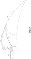
- FIG. 2 illustrates an aircraft structure in the form of a spoiler 200 provided on the wing 104 of the aircraft 100.
- the spoiler 200 may have a neutral position, as shown in FIG. 2 , in which the spoiler overlies a wing 104 of the aircraft 100.
- the spoiler 200 may be rotated from the neutral position to alter an aerodynamic characteristic of the aircraft, such as lift, in a controlled manner.
- the spoiler 200 includes fittings, such as actuator lugs 202 configured for attachment to an actuator 206.
- the actuator 206 may operate to move the spoiler 200 from the neutral position.
- FIGS. 3-9 illustrate a first example of a spoiler 200.
- the spoiler 200 generally includes a sub-frame 210 having a side wall 212, with a first outer surface 214 is coupled to the side wall 212.
- a second outer surface 216 is also coupled to the side wall 212 opposite the first outer surface 214.
- the first and second outer surfaces 214, 216 correspond to upper and lower aerodynamic surfaces of the spoiler 200. That is, the first and second outer surfaces 214, 216 may be directly exposed to ambient air during flight of the aircraft 100, and therefore may be positioned to affect one or more aerodynamic characteristics of the wing 104, such as magnitude of lift.
- Apertures 218, 220 are formed in the first outer surface 214 while an aperture 222 is shown formed in the second outer surface 216.
- the spoiler 200 includes a plurality of stiffening webs that extend between the first outer surface 214 and the second outer surface 216, thereby to improve the structural strength of the assembled aircraft structure.
- a first stiffening web 230 extends between the first outer surface 214 and the second outer surface 216, and further extends at least partially around the aperture 218 formed in the first outer surface 214.
- the aperture 218, first stiffening web 230, and second outer surface 216 define a first stiffening recess 232.
- a second stiffening web 234 also extends between the first outer surface 214 and the second outer surface 216, and further extends at least partially around the aperture 220 formed in the first outer surface 214.
- the aperture 220, second stiffening web 234, and second outer surface 216 define a second stiffening recess 236. Still further, a third stiffening web 238 extends between the first outer surface 214 and the second outer surface 216, and further extends at least partially around the aperture 222 formed in the second outer surface 216.
- the aperture 222, third stiffening web 238, and first outer surface 214 define a third stiffening recess 240.
- portions of the stiffening webs may border more than one stiffening recess.
- a first common web portion 242 may form parts of both the first stiffening web 230, which borders the first stiffening recess 232, and the third stiffening web 238, which borders the third stiffening recess 240.
- a second common web portion 244 may form parts of both the second stiffening web 234, which borders the second stiffening recess 236, and the third stiffening web 238, which borders the third stiffening recess 240.
- the stiffening recesses may span the entire width of the spoiler 200 to improve the structural integrity of the spoiler.
- the spoiler 200 may further include a fourth stiffening recess 246 defined by the first stiffening web 230, side wall 212, and first outer surface 214, and a fifth stiffening recess 248 defined by the second stiffening web 234, side wall 212, and first outer surface 214.
- the stiffening recesses may be oriented so that adjacent recesses face opposite outer surfaces of the spoiler 200, so that the stiffener webs and outer surfaces form a corrugated structure that reinforces the spoiler 200.
- first and second stiffening recesses 232, 236 face toward the first outer surface 214, while the third, fourth, and fifth stiffening recesses 240, 246, 248 face toward the second outer surface 216.
- first outer surface 214 defines a first raised stiffening section 250, adjacent to both the first stiffening recess 232 and the second stiffening recess 236, that spans across and forms a portion of the third stiffening recess 240.
- the second outer surface 216 defines a second raised stiffening section 252, adjacent to both the third stiffening recess 240 and the fourth stiffening recess 246, that spans across and defines a portion of the first stiffening recess 232.
- the second outer surface 216 defines a third raised stiffening section 254, adjacent to both the third stiffening recess 240 and the fifth stiffening recess 248, that spans across and defines a portion of the second stiffening recess 236.
- the spoiler 200 further includes skin plates for closing off the stiffening recesses, thereby to complete the first and second outer surfaces 214, 216 and improve the aerodynamic performance of the spoiler 200.
- a first skin plate 260 is sized to extend over the first stiffening recess 232 and is shaped conformally with the aperture 218.
- a second skin plate 262 is sized to extend over the second stiffening recess 236 and is shaped conformally with the aperture 220.
- a third skin plate 264 is sized to extend over the third stiffening recess 240 and is shaped conformally with the aperture 222. While the fourth and fifth stiffening recesses 246, 248 are shown as being open to the exterior of the spoiler 200, additional skin plates may be provided to close off these recesses.
- the stiffening webs may include mating surfaces that securely position the skin plates in place to facilitate joining of the skin plates to the sub-frame 210.
- the first stiffening web 230 includes a first mating surface 266.
- the first mating surface 266 may be substantially planar (i.e., is within manufacturing tolerances associated with metal bending, cutting, rolling, and shaping techniques) to conform to a perimeter of the first skin plate 260. Accordingly, in the illustrated example, the first mating surface 266 is a relatively narrow strip extending around a perimeter of the first stiffening recess 232.
- the first mating surface 266 further may be inwardly offset from the first outer surface 214 by a first offset distance 268.
- the first offset distance is substantially equal (i.e., is within manufacturing tolerances associated with metal bending, cutting, rolling, and shaping techniques) to a first skin plate thickness 270, so that a first skin plate outer surface 272 is aligned with the first outer surface 214.
- the second stiffening web 234 includes a second mating surface 274 that is substantially planar to conform to a perimeter of the second skin plate 262, thereby to form a relatively narrow strip extending around a perimeter of the second stiffening recess 236.
- the second mating surface 274 is inwardly offset from the first outer surface 214 by a second offset distance 276 that is substantially equal to a second skin plate thickness 278, so that a second skin plate outer surface 279 is aligned with the first outer surface 214 ( FIGS. 6 & 9 ).
- the third stiffening web 238 includes a third mating surface 280 that is substantially planar to conform to a perimeter of the third skin plate 264, thereby to form a relatively narrow strip extending around a perimeter of the third stiffening recess 240.
- the third mating surface 280 is inwardly offset from the second outer surface 216 by a third offset distance 282 that is substantially equal to a third skin plate thickness 284, so that a third skin plate outer surface 285 is aligned with the second outer surface 216 ( FIG. 9 ).
- the skin plates 260, 262, 264 are joined to the sub-frame 210 using friction stir welded seams, thereby to form a monolithic aircraft structure having reduced weight, improved structural integrity, superior aerodynamic characteristics.
- the first skin plate 260 is joined to the first mating surface 266 of the first stiffening web 230 at a first friction stir welded seam 300.
- the second skin plate 262 is joined to the second mating surface 274 of the second stiffening web 234 at a second friction stir welded seam 302, while the third skin plate 264 is joined to the third mating surface 280 of the third stiffening web 238 at a third friction stir welded seam 304.
- the friction stir welded seams 300, 302, 304 may be formed using a friction stir welding tool having a pin. During the friction stir welding process, the pin of the friction stir welding tool is rotated and forced through the skin plate and into the associated stiffening web of the sub-frame 210. Heat and pressure generated by the friction stir welding tool mechanically intermixes portions of the stiffening web and the skin plate to form the friction stir welded seam.
- the friction stir welded seams 300, 302, 304 extend continuously around the perimeters of the skin plates 260, 262, 264, however in alternative examples the friction stir welded seams 300, 302, 304 may be intermittent around the perimeter of the skin plates 260, 262, 264.
- the recesses and skin plates help to provide a clearly defined path for the friction stir welding tool to follow while forming friction stir welded seams, which helps to facilitate attachment of aerodynamic skin plates. Further, the clearly defined path and the mating surfaces help to contain the weld without backside exposure (e.g., exposure of the weld at the bottom of the recess to which the skin plate is friction stir welded).
- the friction stir welded seams 300, 302, 304 may be formed in different patterns as they extend around the perimeters of the skin plates 260, 262, 264.
- each of the first, second, and third friction stir welded seams 300, 302, 304 may be formed by weld lines having linear path segments 310 joined by curved corner segments 312.
- the weld line used to form the first, second, and third friction stir welded seams 300, 302, 304 may be intermittently or continuously non-linear, which may limit propagation of cracks and improve structural integrity by increasing a length of the weld.
- the left-hand side of FIG. 10 and FIG. 11 show a non-linear weld line 314 that is at least partially formed in a continuous sinusoidal wave or scalloped pattern. Still other weld line patterns, such as a chevron, may be used.
- first and second lugs 320, 322 are coupled to the side wall 212 to provide connection points to the wing 104 of the aircraft 100.
- the first and second lugs 320, 322 are laterally spaced to define an intermediate region 324 of the side wall 212 that extends between the first and second lugs 320, 322.
- the first and second lugs 320, 322, and the intermediate region 324 form an area of the spoiler 200 having relatively greater structural integrity.
- the stiffening webs may be configured to direct loads toward this area of the spoiler 200.
- the stiffening webs may include web segments traversing paths that are aligned with the intermediate region 324 of the side wall 212.
- the first stiffening web 230 includes web segments 330, 332 and the second stiffening web 234 includes web segments 334, 336, wherein each of the web segments 330, 332, 334, 336 is aligned with the intermediate region 324.
- the third stiffening web 238 includes web segments 338, 340 that are aligned with the intermediate region 324.
- FIG. 12 schematically illustrates a method 400 of forming a monolithic aircraft structure having multiple aerodynamic surfaces.
- the method begins at block 402 by forming the sub-frame 210.
- the sub-frame 210 includes the side wall 212, the first and second outer surfaces 214, 216 coupled to the side wall 212, and the first and second stiffening webs 230, 234 extending between the first and second outer surfaces 214, 216 and at least partially around the first and second apertures 218, 220.
- the method 400 may include, at block 404, forming skin plates.
- the skin plates may include the first skin plate 260 sized to extend over the first stiffening recess 232 , the second skin plate 262 sized to extend over the second stiffening recess 236, and the third skin plate 264 sized to extend over the third stiffening recess 240.
- the method 400 may optionally include a dimensional inspection of the sub-frame and the skin plates at block 406, to ensure that the components meet the desired size specifications.
- the method 400 may continue by positioning the skin plates relative to the sub-frame, so that the sub-frame mating surfaces engage perimeters of the skin plates.
- the method 400 includes friction stir welding the skin plates to the sub-frame to form friction stir welded seams between the sub-frame and the skin plates, thereby to form a monolithic aircraft structure.
- friction stir welding the first skin plate 260 to the first stiffening web 230 includes forming at least a portion of the first friction stir welded seam 300 with a continuous sinusoidal wave pattern
- friction stir welding the second skin plate 262 to the second stiffening web 234 includes forming at least a portion of the second friction stir welded seam 302 with a continuous sinusoidal wave pattern.
- the second aperture 220 is formed in the first outer surface 214
- forming the sub-frame 210 further includes a third stiffening web 238 extending between the first outer surface 214 and the second outer surface 216, the third stiffening web 238 extending at least partially around a third aperture 222 formed in the second outer surface 216 to define a third stiffening recess 240.
- the method 400 further includes joining a third skin plate 264 to the third stiffening web 238 with a third friction welded seam 304, wherein the third skin plate 264 is sized to extend over the third stiffening recess 240 and shaped conformally with the third aperture 222.
- forming the sub-frame 210 at block 402 further includes forming a first lug 320 and a second lug 322 on the side wall 212 to define an intermediate region 324 of the side wall 212 extending between the first lug 320 and the second lug 322, and wherein each of the first stiffening web 230 and the second stiffening web 234 includes at least two web segments traversing paths aligned with the intermediate region 324 of the side wall 212.
- the method 400 may include several optional steps after the friction stir welded seams are formed. For example, at block 412, the assembled sub-frame and skin components are heat treated to improve structural integrity of the spoiler 200. At block 414, nondestructive inspection of the friction stir welded seams is performed to ensure that the spoiler 200 is structurally sound. Finally, at block 416, at least one surface treatment selected from a group of surface treatments consisting of anodizing, primer coating, and topcoating is applied to the spoiler 200, thereby to improve aerodynamic qualities (e.g., reducing drag) over the aerodynamic surfaces.
- aerodynamic qualities e.g., reducing drag
- the disclosed aircraft control structure and method help to provide clearly defined paths for a friction stir welding tool to follow while forming friction stir welded seams, which helps to facilitate attachment of aerodynamic skin plates.
- the disclosed aircraft control structure and method also help to improve the structural strength of the assembled aircraft control structure.
Landscapes
- Engineering & Computer Science (AREA)
- Aviation & Aerospace Engineering (AREA)
- Manufacturing & Machinery (AREA)
- Mechanical Engineering (AREA)
- Transportation (AREA)
- Pressure Welding/Diffusion-Bonding (AREA)
Abstract
Description
- The present disclosure generally relates to aircraft structures and methods and, more specifically, to friction stir welded aircraft structures having multiple aerodynamic surfaces and methods of forming such structures.
- Structures used on aircraft may have aerodynamic surfaces (i.e., control surfaces) that are exposed to ambient air during flight. These structures may be formed of two or more components that are joined together. An aircraft spoiler, for example, typically includes multiple components that are fastened or bonded together to form the complete spoiler. One configuration of a spoiler is a monolithic, machined body having a cover attached for aerodynamic purposes. The body has an outer surface facing away from the aircraft wing that is continuously exposed to ambient air during flight. The cover also has an outer surface that typically overlies a flap of the aircraft when in a neutral position, but may move to a deployed position in which the outer surface of the cover is spaced from the flap. Traditional methods of joining such components, such as bolting, require additional labor and expense, add to the weight of the aircraft, and introduce aerodynamic drag.
- There is, therefore, a need for improved spoilers and methods of joining spoiler components.
- In accordance with one example, an aircraft control structure includes a side wall, a first outer surface coupled to the side wall, and a second outer surface coupled to the side wall and opposite the first outer surface. A first stiffening web extends between the first outer surface and the second outer surface, the first stiffening web extending at least partially around a first aperture formed in the first outer surface to define a first stiffening recess. A second stiffening web extends between the first outer surface and the second outer surface, the second stiffening web extending at least partially around a second aperture formed in the first outer surface or the second outer surface to define a second stiffening recess. A first skin plate is sized to extend over the first stiffening recess and shaped conformally with the first aperture, wherein the first skin plate is joined to the first stiffening web at a first friction stir welded seam. A second skin plate is sized to extend over the second stiffening recess and shaped conformally with the second aperture, wherein the second skin plate is joined to the second stiffening web at a second friction stir welded seam.
- In accordance with another example, an aircraft spoiler includes a side wall, an upper aerodynamic surface coupled to the side wall, and a lower aerodynamic surface coupled to the side wall and opposite the upper aerodynamic surface. A first stiffening web extends between the upper aerodynamic surface and the lower aerodynamic surface, the first stiffening web also extending at least partially around a first aperture formed in the upper aerodynamic surface to define a first stiffening recess, wherein the first stiffening web includes a first mating surface inwardly offset from the upper aerodynamic surface. A second stiffening web extends between the upper aerodynamic surface and the lower aerodynamic surface, the second stiffening web also extending at least partially around a second aperture formed in the upper aerodynamic surface to define a second stiffening recess, wherein the second stiffening web including a second mating surface inwardly offset from the upper aerodynamic surface. A first skin plate is sized to extend over the first stiffening recess and shaped conformally with the first aperture, wherein the first skin plate is joined to the first mating surface of the first stiffening web at a first friction stir welded seam. A second skin plate is sized to extend over the second stiffening recess and shaped conformally with the second aperture, wherein the second skin plate is joined to the second mating surface of the second stiffening web at a second friction stir welded seam.
- In accordance with yet another example, a method of forming a monolithic aircraft structure having multiple aerodynamic surfaces includes forming a sub-frame with a side wall, a first outer surface coupled to the side wall, and a second outer surface coupled to the side wall and opposite the first outer surface. The sub-frame is further formed with a first stiffening web extending between the first outer surface and the second outer surface, the first stiffening web extending at least partially around a first aperture formed in the first outer surface to define a first stiffening recess, and a second stiffening web extending between the first outer surface and the second outer surface, the second stiffening web extending at least partially around a second aperture formed in the first outer surface or the second outer surface to define a second stiffening recess. The method includes friction stir welding a first skin plate to the first stiffening web to form a first friction stir welded seam, wherein the first skin plate is sized to extend over the first stiffening recess and shaped conformally with the first aperture. The method further includes friction stir welding a second skin plate to the second stiffening web to form a second friction stir welded seam, wherein the second skin plate is sized to extend over the second stiffening recess and shaped conformally with the second aperture.
- In another aspect of the disclosure that may be combined with any of these aspects, the first stiffening web includes a first mating surface inwardly offset from the first outer surface, and in which the first friction stir welded seam joins the first skin plate to the first mating surface of the first stiffening web.
- In another aspect of the disclosure that may be combined with any of these aspects, the first skin plate has a first skin plate thickness, and the first mating surface of the first stiffening web is spaced from the first outer surface by an offset distance substantially equal to the first skin plate thickness.
- In another aspect of the disclosure that may be combined with any of these aspects, each of the first friction stir welded seam and the second friction stir welded seam comprises a plurality of linear weld line segments.
- In another aspect of the disclosure that may be combined with any of these aspects, portions of each of the first friction stir welded seam and the second friction stir welded seam comprise continuously non-linear weld lines.
- In another aspect of the disclosure that may be combined with any of these aspects, the continuously non-linear weld lines comprise continuous sinusoidal wave patterns.
- In another aspect of the disclosure that may be combined with any of these aspects, first and second lugs are coupled to the side wall to define an intermediate region of the side wall extending between the first and second lugs, and each of the first stiffening web and the second stiffening web includes at least two web segments traversing paths aligned with the intermediate region of the side wall.
- In another aspect of the disclosure that may be combined with any of these aspects, the second aperture is formed in the first outer surface and the aircraft control structure further includes a third stiffening web extending between the first outer surface and the second outer surface, wherein the third stiffening web also extends at least partially around a third aperture formed in the second outer surface to define a third stiffening recess, and a third skin plate is sized to extend over the third stiffening recess and shaped conformally with the third aperture, wherein the third skin plate is joined to the third stiffening web at a third friction stir welded seam.
- In another aspect of the disclosure that may be combined with any of these aspects, the second aperture is formed in the second outer surface, the first outer surface defines a first raised stiffening section adjacent the first stiffening recess, the second outer surface defines a second raised stiffening section adjacent the second stiffening recess, the first raised stiffening section spans across and defines a portion of the second stiffening recess, and the second raised stiffening section spans across and defines a portion of the first stiffening recess.
- In another aspect of the disclosure that may be combined with any of these aspects, the first outer surface comprises an upper aerodynamic surface of a spoiler and the second outer surface comprises a lower aerodynamic surface of the spoiler.
- These and other aspects and features will become more readily apparent upon reading the following detailed description when taken in conjunction with the accompanying drawings. In addition, although various features are disclosed in relation to specific examples, it is understood that the various features may be combined with each other, or used alone, with any of the various examples without departing from the scope of the disclosure.
-
-
FIG. 1 is a perspective view of an example aircraft that may be used to implement the methods and apparatus disclosed herein. -
FIG. 2 is a partially schematic side elevation view of a wing of the aircraft ofFIG. 1 . -
FIG. 3 is a top perspective view of a of a sub-frame of a spoiler used on the wing ofFIG. 2 . -
FIG. 4 is a bottom perspective view of the sub-frame of the spoiler ofFIG. 3 -
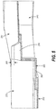
FIG. 5 is a side elevation view, in cross-section, of a portion of the spoiler ofFIGS. 3 and 4 . -
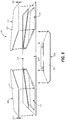
FIG. 6 is an exploded view of the spoiler showing the sub-frame, two top skin plates, and a bottom skin plate. -
FIG. 7 is a top perspective view of the spoiler showing the top skin plates friction stir welded to the sub-frame. -
FIG. 8 is a bottom perspective view of the spoiler showing the bottom skin plate friction stir welded to the sub-frame. -
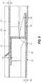
FIG. 9 is a side elevation view, in cross-section, of a portion of the spoiler taken along line 9-9 ofFIG. 8 . -
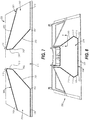
FIG. 10 is a top perspective view of an alternative example of a spoiler having a top skin plate joined to the sub-frame by a friction stir weld having a non-linear weld line. -
FIG. 11 is a side elevation view, in cross-section, of a portion of the spoiler ofFIG. 10 . -
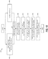
FIG. 12 is a schematic flowchart illustrating a method of forming a monolithic aircraft structure having multiple aerodynamic surfaces, according to the present disclosure. - It should be understood that the drawings are not necessarily drawn to scale and that the disclosed examples are sometimes illustrated schematically. It is to be further appreciated that the following detailed description is merely exemplary in nature and is not intended to limit the disclosure or the application and uses thereof. Hence, although the present disclosure is, for convenience of explanation, depicted and described as certain illustrative examples, it will be appreciated that it can be implemented in various other types of examples and in various other systems and environments.
- The following detailed description is of the best currently contemplated modes of carrying out the disclosure. The description is not to be taken in a limiting sense, but is made merely for the purpose of illustrating the general principles of the disclosure, since the scope of the disclosure is best defined by the appended claims.
- Aircraft structures having multiple aerodynamic surfaces, and methods for forming such structures, are disclosed herein having reduced weight and aerodynamic drag. An exemplary aircraft structure includes a sub-frame defining first and second aerodynamic surfaces. Skin plates are joined to the sub-frame by friction stir welded seams to form a monolithic structure. The friction stir welded seams may be continuous or intermittent about a perimeter of the skin plates. Joining the sub-frame and skin plates using friction stir welds avoids the assembly expense, weight, and aerodynamic drag associated with the use of fasteners.
- As used in the examples disclosed herein, the terms "aerodynamic surface" and "control surface" are used interchangeably to refer to a component and/or a surface that defines an aerodynamic flow surface used to control flight and/or navigation of an aircraft or other vehicle based on fluid flow (e.g., airflow during movement and/or flight). For example, the term "control surface" encompasses a surface of an aerodynamic structure (e.g., a top surface of a flap) or an actively displaced and/or rotated component such as a flap, spoiler or aileron, for example. As used herein, the term "a chord length" refers to a length along a flow path or airflow direction along a direction of travel of an aircraft, unless described otherwise. As used herein the term "angle from horizontal" of an aircraft refers to an angle and/or relative angles corresponding to a reference plane defined as an angle away from a neutral position of a control surface, whereas the term "horizontal" in this context refers to the neutral position and/or angle of the control surface. As used herein, the term "upper surface" refers to a top surface (e.g., a wing top surface) of an aircraft on opposite side from landing gear of the aircraft while the term "lower surface" refers to a bottom surface side (e.g., a wing bottom surface) that corresponds to the landing gear.
-
FIG. 1 illustrates anexample aircraft 100 in which the examples disclosed herein may be implemented. In the illustrated example, theaircraft 100 includesstabilizers 102 andwings 104 attached to afuselage 106. Thewings 104 of the illustrated example have control surfaces (e.g., flaps, ailerons, spoilers, tabs, etc.) 108, some of which are located at a trailing edge of thewings 104 and may be displaced or adjusted (e.g., angled, etc.) to provide lift during takeoff, landing and/or flight maneuvers. In some examples, thecontrol surfaces 108 are operated (i.e., displaced) independently of one another. The control surfaces 108 include leading edge flaps 109, leadingedge slats 110, upper surface spoilers (e.g., flight spoilers, ground spoilers, upper surface spoilers, etc.) 112, and trailing edge flaps (e.g., rotatable flaps) 114. The control surfaces 108 of the illustrated example also includeailerons 118 andflaperons 120. In this example, thestabilizers 102 includeelevators 122 and arudder 123. Thewings 104 also define upper and lower surfaces (e.g., upper and lower sides, upper and lower aerodynamic surfaces, etc.) 124, 126, respectively. - To control flight of the
aircraft 100, theupper surface spoilers 112 of the illustrated example alter the lift and drag of theaircraft 100. The trailing edge flaps 114 alter the lift and pitch of theaircraft 100. Theflaperons 120 and theailerons 118 of the illustrated example alter the roll of theaircraft 100. In this example, theedge slats 110 alter the lift of theaircraft 100. The control surfaces 108 of the illustrated example also play a role in controlling the speed of theaircraft 100. For example, theupper surface spoilers 112 may be used for braking of theaircraft 100. Any of thecontrol surfaces 108 of the illustrated example may be independently moved (e.g., deflected) to control the load distribution in different directions over thewing 104, thereby directing movement of theaircraft 100. - The examples described herein may be applied to control surfaces associated with any of the
stabilizers 102, thewings 104 and/or any other exterior or outboard structure (e.g., a horizontal stabilizer, a wing strut, an engine strut, a canard stabilizer, etc.) of theaircraft 100. In particular, thewings 104 and/or thestabilizers 102 havecontrol surfaces 108 that can be adjusted to maneuver theaircraft 100 and/or control a speed of theaircraft 100, for example. Additionally or alternatively, in some examples, thefuselage 106 has control surfaces, which may be deflected, to alter the flight maneuvering characteristics during cruise and/or takeoff of theaircraft 100. -
FIG. 2 illustrates an aircraft structure in the form of aspoiler 200 provided on thewing 104 of theaircraft 100. Thespoiler 200 may have a neutral position, as shown inFIG. 2 , in which the spoiler overlies awing 104 of theaircraft 100. Thespoiler 200, however, may be rotated from the neutral position to alter an aerodynamic characteristic of the aircraft, such as lift, in a controlled manner. Thespoiler 200 includes fittings, such as actuator lugs 202 configured for attachment to anactuator 206. Theactuator 206 may operate to move thespoiler 200 from the neutral position. -
FIGS. 3-9 illustrate a first example of aspoiler 200. As best shown inFIGS. 3 and 4 , thespoiler 200 generally includes asub-frame 210 having aside wall 212, with a firstouter surface 214 is coupled to theside wall 212. A secondouter surface 216 is also coupled to theside wall 212 opposite the firstouter surface 214. In the illustrated example, the first and secondouter surfaces spoiler 200. That is, the first and secondouter surfaces aircraft 100, and therefore may be positioned to affect one or more aerodynamic characteristics of thewing 104, such as magnitude of lift.Apertures outer surface 214 while anaperture 222 is shown formed in the secondouter surface 216. - The
spoiler 200 includes a plurality of stiffening webs that extend between the firstouter surface 214 and the secondouter surface 216, thereby to improve the structural strength of the assembled aircraft structure. As best shown inFIGS. 3-5 , afirst stiffening web 230 extends between the firstouter surface 214 and the secondouter surface 216, and further extends at least partially around theaperture 218 formed in the firstouter surface 214. Accordingly, theaperture 218, first stiffeningweb 230, and secondouter surface 216 define afirst stiffening recess 232. Asecond stiffening web 234 also extends between the firstouter surface 214 and the secondouter surface 216, and further extends at least partially around theaperture 220 formed in the firstouter surface 214. Theaperture 220,second stiffening web 234, and secondouter surface 216 define asecond stiffening recess 236. Still further, athird stiffening web 238 extends between the firstouter surface 214 and the secondouter surface 216, and further extends at least partially around theaperture 222 formed in the secondouter surface 216. Theaperture 222,third stiffening web 238, and firstouter surface 214 define athird stiffening recess 240. - To minimize weight, portions of the stiffening webs may border more than one stiffening recess. For example, a first
common web portion 242 may form parts of both thefirst stiffening web 230, which borders thefirst stiffening recess 232, and thethird stiffening web 238, which borders thethird stiffening recess 240. Similarly, a secondcommon web portion 244 may form parts of both thesecond stiffening web 234, which borders thesecond stiffening recess 236, and thethird stiffening web 238, which borders thethird stiffening recess 240. - The stiffening recesses may span the entire width of the
spoiler 200 to improve the structural integrity of the spoiler. For example, as best shown inFIG. 4 , thespoiler 200 may further include afourth stiffening recess 246 defined by thefirst stiffening web 230,side wall 212, and firstouter surface 214, and afifth stiffening recess 248 defined by thesecond stiffening web 234,side wall 212, and firstouter surface 214. The stiffening recesses may be oriented so that adjacent recesses face opposite outer surfaces of thespoiler 200, so that the stiffener webs and outer surfaces form a corrugated structure that reinforces thespoiler 200. In the illustrated example, the first and second stiffening recesses 232, 236 face toward the firstouter surface 214, while the third, fourth, and fifth stiffening recesses 240, 246, 248 face toward the secondouter surface 216. Accordingly, the firstouter surface 214 defines a first raisedstiffening section 250, adjacent to both thefirst stiffening recess 232 and thesecond stiffening recess 236, that spans across and forms a portion of thethird stiffening recess 240. Similarly, the secondouter surface 216 defines a second raisedstiffening section 252, adjacent to both thethird stiffening recess 240 and thefourth stiffening recess 246, that spans across and defines a portion of thefirst stiffening recess 232. Still further, the secondouter surface 216 defines a third raisedstiffening section 254, adjacent to both thethird stiffening recess 240 and thefifth stiffening recess 248, that spans across and defines a portion of thesecond stiffening recess 236. - The
spoiler 200 further includes skin plates for closing off the stiffening recesses, thereby to complete the first and secondouter surfaces spoiler 200. As best shown inFIG. 6 , afirst skin plate 260 is sized to extend over thefirst stiffening recess 232 and is shaped conformally with theaperture 218. Similarly, asecond skin plate 262 is sized to extend over thesecond stiffening recess 236 and is shaped conformally with theaperture 220. Still further, athird skin plate 264 is sized to extend over thethird stiffening recess 240 and is shaped conformally with theaperture 222. While the fourth and fifth stiffening recesses 246, 248 are shown as being open to the exterior of thespoiler 200, additional skin plates may be provided to close off these recesses. - The stiffening webs may include mating surfaces that securely position the skin plates in place to facilitate joining of the skin plates to the
sub-frame 210. For example, as best shown inFIGS. 3-6 , thefirst stiffening web 230 includes afirst mating surface 266. Thefirst mating surface 266 may be substantially planar (i.e., is within manufacturing tolerances associated with metal bending, cutting, rolling, and shaping techniques) to conform to a perimeter of thefirst skin plate 260. Accordingly, in the illustrated example, thefirst mating surface 266 is a relatively narrow strip extending around a perimeter of thefirst stiffening recess 232. Thefirst mating surface 266 further may be inwardly offset from the firstouter surface 214 by a first offsetdistance 268. The first offset distance is substantially equal (i.e., is within manufacturing tolerances associated with metal bending, cutting, rolling, and shaping techniques) to a firstskin plate thickness 270, so that a first skin plateouter surface 272 is aligned with the firstouter surface 214. - Similarly, the
second stiffening web 234 includes asecond mating surface 274 that is substantially planar to conform to a perimeter of thesecond skin plate 262, thereby to form a relatively narrow strip extending around a perimeter of thesecond stiffening recess 236. Thesecond mating surface 274 is inwardly offset from the firstouter surface 214 by a second offsetdistance 276 that is substantially equal to a secondskin plate thickness 278, so that a second skin plateouter surface 279 is aligned with the first outer surface 214 (FIGS. 6 &9 ). - Still further, the
third stiffening web 238 includes athird mating surface 280 that is substantially planar to conform to a perimeter of thethird skin plate 264, thereby to form a relatively narrow strip extending around a perimeter of thethird stiffening recess 240. Thethird mating surface 280 is inwardly offset from the secondouter surface 216 by a third offsetdistance 282 that is substantially equal to a thirdskin plate thickness 284, so that a third skin plateouter surface 285 is aligned with the second outer surface 216 (FIG. 9 ). - The
skin plates sub-frame 210 using friction stir welded seams, thereby to form a monolithic aircraft structure having reduced weight, improved structural integrity, superior aerodynamic characteristics. Referring toFIGS. 7-9 , thefirst skin plate 260 is joined to thefirst mating surface 266 of thefirst stiffening web 230 at a first friction stir weldedseam 300. Similarly, thesecond skin plate 262 is joined to thesecond mating surface 274 of thesecond stiffening web 234 at a second friction stir weldedseam 302, while thethird skin plate 264 is joined to thethird mating surface 280 of thethird stiffening web 238 at a third friction stir weldedseam 304. The friction stir weldedseams sub-frame 210. Heat and pressure generated by the friction stir welding tool mechanically intermixes portions of the stiffening web and the skin plate to form the friction stir welded seam. In the illustrated examples, the friction stir weldedseams skin plates seams skin plates - The friction stir welded
seams skin plates FIGS. 7, 8 , and the right-hand side ofFIG. 10 , each of the first, second, and third friction stir weldedseams linear path segments 310 joined bycurved corner segments 312. Alternatively, the weld line used to form the first, second, and third friction stir weldedseams FIG. 10 andFIG. 11 , for example, show anon-linear weld line 314 that is at least partially formed in a continuous sinusoidal wave or scalloped pattern. Still other weld line patterns, such as a chevron, may be used. - Within examples, the stiffening webs are configured to direct loads to an area of the
spoiler 200 having relatively greater structural strength, thereby to improve the performance and life of thespoiler 200. More specifically, first andsecond lugs side wall 212 to provide connection points to thewing 104 of theaircraft 100. The first andsecond lugs intermediate region 324 of theside wall 212 that extends between the first andsecond lugs second lugs intermediate region 324 form an area of thespoiler 200 having relatively greater structural integrity. The stiffening webs may be configured to direct loads toward this area of thespoiler 200. - Specifically, the stiffening webs may include web segments traversing paths that are aligned with the
intermediate region 324 of theside wall 212. Referring toFIG. 3 , thefirst stiffening web 230 includesweb segments second stiffening web 234 includesweb segments web segments intermediate region 324. Referring toFIG. 4 , thethird stiffening web 238 includesweb segments intermediate region 324. By providing multiple web segments that are aligned with theintermediate region 324, loads applied to thespoiler 200 are directed to thelugs spoiler 200. -
FIG. 12 schematically illustrates amethod 400 of forming a monolithic aircraft structure having multiple aerodynamic surfaces. The method begins atblock 402 by forming thesub-frame 210. Within examples, thesub-frame 210 includes theside wall 212, the first and secondouter surfaces side wall 212, and the first and second stiffeningwebs outer surfaces second apertures method 400 may include, at block 404, forming skin plates. The skin plates may include thefirst skin plate 260 sized to extend over thefirst stiffening recess 232 , thesecond skin plate 262 sized to extend over thesecond stiffening recess 236, and thethird skin plate 264 sized to extend over thethird stiffening recess 240. Themethod 400 may optionally include a dimensional inspection of the sub-frame and the skin plates atblock 406, to ensure that the components meet the desired size specifications. - At
block 408, themethod 400 may continue by positioning the skin plates relative to the sub-frame, so that the sub-frame mating surfaces engage perimeters of the skin plates. Continuing atblock 410, themethod 400 includes friction stir welding the skin plates to the sub-frame to form friction stir welded seams between the sub-frame and the skin plates, thereby to form a monolithic aircraft structure. - In an example, friction stir welding the
first skin plate 260 to thefirst stiffening web 230 includes forming at least a portion of the first friction stir weldedseam 300 with a continuous sinusoidal wave pattern, and friction stir welding thesecond skin plate 262 to thesecond stiffening web 234 includes forming at least a portion of the second friction stir weldedseam 302 with a continuous sinusoidal wave pattern. - In an example, the
second aperture 220 is formed in the firstouter surface 214, and forming thesub-frame 210 further includes athird stiffening web 238 extending between the firstouter surface 214 and the secondouter surface 216, thethird stiffening web 238 extending at least partially around athird aperture 222 formed in the secondouter surface 216 to define athird stiffening recess 240. In this example, themethod 400 further includes joining athird skin plate 264 to thethird stiffening web 238 with a third friction weldedseam 304, wherein thethird skin plate 264 is sized to extend over thethird stiffening recess 240 and shaped conformally with thethird aperture 222. - In an example, forming the
sub-frame 210 atblock 402 further includes forming afirst lug 320 and asecond lug 322 on theside wall 212 to define anintermediate region 324 of theside wall 212 extending between thefirst lug 320 and thesecond lug 322, and wherein each of thefirst stiffening web 230 and thesecond stiffening web 234 includes at least two web segments traversing paths aligned with theintermediate region 324 of theside wall 212. - The
method 400 may include several optional steps after the friction stir welded seams are formed. For example, atblock 412, the assembled sub-frame and skin components are heat treated to improve structural integrity of thespoiler 200. Atblock 414, nondestructive inspection of the friction stir welded seams is performed to ensure that thespoiler 200 is structurally sound. Finally, atblock 416, at least one surface treatment selected from a group of surface treatments consisting of anodizing, primer coating, and topcoating is applied to thespoiler 200, thereby to improve aerodynamic qualities (e.g., reducing drag) over the aerodynamic surfaces. - Beneficially, the disclosed aircraft control structure and method help to provide clearly defined paths for a friction stir welding tool to follow while forming friction stir welded seams, which helps to facilitate attachment of aerodynamic skin plates. The disclosed aircraft control structure and method also help to improve the structural strength of the assembled aircraft control structure.
- Further, the disclosure comprises examples according to the following clauses:
- Clause 1. An aircraft control structure, comprising:
- a side wall;
- a first outer surface coupled to the side wall;
- a second outer surface coupled to the side wall and opposite the first outer surface
- a first stiffening web extending between the first outer surface and the second outer surface, the first stiffening web extending at least partially around a first aperture formed in the first outer surface to define a first stiffening recess;
- a second stiffening web extending between the first outer surface and the second outer surface, the second stiffening web extending at least partially around a second aperture formed in the first outer surface or the second outer surface to define a second stiffening recess;
- a first skin plate sized to extend over the first stiffening recess and shaped conformally with the first aperture, wherein the first skin plate is joined to the first stiffening web at a first friction stir welded seam; and
- a second skin plate sized to extend over the second stiffening recess and shaped conformally with the second aperture, wherein the second skin plate is joined to the second stiffening web at a second friction stir welded seam.
- Clause 2. The aircraft control structure of clause 1, in which the first stiffening web includes a first mating surface inwardly offset from the first outer surface, and in which the first friction stir welded seam joins the first skin plate to the first mating surface of the first stiffening web.
- Clause 3. The aircraft control structure of clause 2, in which the first skin plate has a first skin plate thickness, and in which the first mating surface of the first stiffening web is spaced from the first outer surface by an offset distance substantially equal to the first skin plate thickness.
- Clause 4. The aircraft control structure of any of clauses 1-3, in which each of the first friction stir welded seam and the second friction stir welded seam comprises a plurality of linear weld line segments.
- Clause 5. The aircraft control structure of any of clauses 1-3, in which portions of each of the first friction stir welded seam and the second friction stir welded seam comprises a continuously non-linear weld line.
- Clause 6. The aircraft control structure of clause 5, in which each continuously non-linear weld line comprises a continuous sinusoidal wave pattern.
- Clause 7. The aircraft control structure of any of clauses 1-6, further comprising first and second lugs coupled to the side wall to define an intermediate region of the side wall extending between the first and second lugs, wherein each of the first stiffening web and the second stiffening web includes at least two web segments traversing paths aligned with the intermediate region of the side wall.
- Clause 8. The aircraft control structure of any of clauses 1-7, in which the second aperture is formed in the first outer surface, the aircraft control structure further comprising:
- a third stiffening web extending between the first outer surface and the second outer surface, the third stiffening web extending at least partially around a third aperture formed in the second outer surface to define a third stiffening recess; and
- a third skin plate sized to extend over the third stiffening recess and shaped conformally with the third aperture, wherein the third skin plate is joined to the third stiffening web at a third friction stir welded seam.
-
Clause 9. The aircraft control structure of any of clauses 1-8, in which:- the second aperture is formed in the second outer surface;
- the first outer surface defines a first raised stiffening section adjacent the first stiffening recess;
- the second outer surface defines a second raised stiffening section adjacent the second stiffening recess;
- the first raised stiffening section spans across and defines a portion of the second stiffening recess; and
- the second raised stiffening section spans across and defines a portion of the first stiffening recess.
- Clause 10. The aircraft control structure of any of clauses 1-9, in which the first outer surface comprises an upper aerodynamic surface of a spoiler and the second outer surface comprises a lower aerodynamic surface of the spoiler.
- Clause 11. An aircraft spoiler, comprising:
- a side wall;
- an upper aerodynamic surface coupled to the side wall;
- a lower aerodynamic surface coupled to the side wall and opposite the upper aerodynamic surface;
- a first stiffening web extending between the upper aerodynamic surface and the lower aerodynamic surface, the first stiffening web extending at least partially around a first aperture formed in the upper aerodynamic surface to define a first stiffening recess, the first stiffening web including a first mating surface inwardly offset from the upper aerodynamic surface;
- a second stiffening web extending between the upper aerodynamic surface and the lower aerodynamic surface, the second stiffening web extending at least partially around a second aperture formed in the upper aerodynamic surface to define a second stiffening recess, the second stiffening web including a second mating surface inwardly offset from the upper aerodynamic surface;
- a first skin plate sized to extend over the first stiffening recess and shaped conformally with the first aperture, wherein the first skin plate is joined to the first mating surface of the first stiffening web at a first friction stir welded seam; and
- a second skin plate sized to extend over the second stiffening recess and shaped conformally with the second aperture, wherein the second skin plate is joined to the second mating surface of the second stiffening web at a second friction stir welded seam.
- Clause 12. The aircraft spoiler of clause 11, in which:
- the first skin plate has a first skin plate thickness;
- the second skin plate has a second skin plate thickness;
- the first mating surface of the first stiffening web is spaced from the upper aerodynamic surface by a first offset distance substantially equal to the first skin plate thickness; and
- the second mating surface of the second stiffening web is spaced from the upper aerodynamic surface by a second offset distance substantially equal to the second skin plate thickness.
- Clause 13. The aircraft spoiler of any of clauses 11-12, further comprising:
- a third stiffening web extending between the upper aerodynamic surface and the lower aerodynamic surface, the third stiffening web extending at least partially around a third aperture formed in the lower aerodynamic surface to define a third stiffening recess, the third stiffening web including a third mating surface inwardly offset from the lower aerodynamic surface; and
- a third skin plate sized to extend over the third stiffening recess and shaped conformally with the third aperture, wherein the third skin plate is joined to the third mating surface of the third stiffening web at a third friction stir welded seam.
- Clause 14. The aircraft spoiler of any of clauses 11-13, in which portions of each of the first friction stir welded seam and the second friction stir welded seam comprises a continuously non-linear weld line.
- Clause 15. The aircraft spoiler of clause 14, in which each continuously non-linear weld line comprises a continuous sinusoidal wave pattern.
- Clause 16. The aircraft spoiler of any of clauses 11-15, further comprising first and second lugs coupled to the side wall to define an intermediate region of the side wall extending between the first and second lugs, wherein each of the first stiffening web and the second stiffening web includes at least two web segments traversing paths aligned with the intermediate region of the side wall.
- Clause 17. A method of forming a monolithic aircraft structure having multiple aerodynamic surfaces, the method comprising:
- forming a sub-frame including:
- a side wall;
- a first outer surface coupled to the side wall;
- a second outer surface coupled to the side wall and opposite the first outer surface;
- a first stiffening web extending between the first outer surface and the second outer surface, the first stiffening web extending at least partially around a first aperture formed in the first outer surface to define a first stiffening recess; and
- a second stiffening web extending between the first outer surface and the second outer surface, the second stiffening web extending at least partially around a second aperture formed in the first outer surface or the second outer surface to define a second stiffening recess;
- friction stir welding a first skin plate to the first stiffening web to form a first friction stir welded seam, wherein the first skin plate is sized to extend over the first stiffening recess and shaped conformally with the first aperture; and
- friction stir welding a second skin plate to the second stiffening web to form a second friction stir welded seam, wherein the second skin plate is sized to extend over the second stiffening recess and shaped conformally with the second aperture.
- forming a sub-frame including:
- Clause 18. The method of clause 17, in which friction stir welding the first skin plate to the first stiffening web comprises forming at least a portion of the first friction stir welded seam with a continuous sinusoidal wave pattern, and in which friction stir welding the second skin plate to the second stiffening web comprises forming at least a portion of the second friction stir welded seam with a continuous sinusoidal wave pattern.
- Clause 19. The method of any of clauses 17-18, in which the second aperture is formed in the first outer surface, and forming the sub-frame further comprises a third stiffening web extending between the first outer surface and the second outer surface, the third stiffening web extending at least partially around a third aperture formed in the second outer surface to define a third stiffening recess, the method further including joining a third skin plate to the third stiffening web with a third friction weld, wherein the third skin plate is sized to extend over the third stiffening recess and shaped conformally with the third aperture.
- Clause 20. The method of any of clauses 17-19, in which forming the sub-frame further includes forming a first lug and a second lug on the side wall to define an intermediate region of the side wall extending between the first lug and the second lug, and wherein each of the first stiffening web and the second stiffening web includes at least two web segments traversing paths aligned with the intermediate region of the side wall.
- All methods described herein can be performed in any suitable order unless otherwise indicated herein or otherwise clearly contradicted by context. The use of any and all examples, or exemplary language (e.g., "such as") provided herein, is intended to illuminate the disclosed subject matter and does not pose a limitation on the scope of the claims. Any statement herein as to the nature or benefits of the exemplary examples is not intended to be limiting, and the appended claims should not be deemed to be limited by such statements. More generally, no language in the specification should be construed as indicating any non-claimed element as being essential to the practice of the claimed subject matter. The scope of the claims includes all modifications and equivalents of the subject matter recited therein as permitted by applicable law. Moreover, any combination of the above-described elements in all possible variations thereof is encompassed by the claims unless otherwise indicated herein or otherwise clearly contradicted by context. Additionally, aspects of the different examples can be combined with or substituted for one another. Finally, the description herein of any reference or patent, even if identified as "prior," is not intended to constitute a concession that such reference or patent is available as prior art against the present disclosure.
Claims (15)
- An aircraft control structure, comprising:a side wall (212);a first outer surface (214) coupled to the side wall (212);a second outer surface (216) coupled to the side wall (212) and opposite the first outer surface (214);a first stiffening web (230) extending between the first outer surface (214) and the second outer surface (216), the first stiffening web (230) extending at least partially around a first aperture (218) formed in the first outer surface (214) to define a first stiffening recess (232);a second stiffening web (234) extending between the first outer surface (214) and the second outer surface (216), the second stiffening web (234) extending at least partially around a second aperture (220) formed in the first outer surface (214) or the second outer surface (216) to define a second stiffening recess (236);a first skin plate (260) sized to extend over the first stiffening recess (232) and shaped conformally with the first aperture (218), wherein the first skin plate (260) is joined to the first stiffening web (230) at a first friction stir welded seam (300); anda second skin plate (262) sized to extend over the second stiffening recess (236) and shaped conformally with the second aperture (220), wherein the second skin plate (262) is joined to the second stiffening web (234) at a second friction stir welded seam (302).
- The aircraft control structure of claim 1, in which the first stiffening web (230) includes a first mating surface (266) inwardly offset from the first outer surface (214), and in which the first friction stir welded seam (300) joins the first skin plate (260) to the first mating surface (266) of the first stiffening web (230).
- The aircraft control structure of claim 2, in which the first skin plate (260) has a first skin plate thickness (270), and in which the first mating surface (266) of the first stiffening web (230) is spaced from the first outer surface (214) by an offset distance substantially equal to the first skin plate thickness (270).
- The aircraft control structure of any of claims 1-3, in which each of the first friction stir welded seam (300) and the second friction stir welded seam (302) comprises a plurality of linear weld line segments.
- The aircraft control structure of any of claims 1-3, in which portions of each of the first friction stir welded seam (300) and the second friction stir welded seam (302) comprise continuously non-linear weld lines (314).
- The aircraft control structure of claim 5, in which each continuously non-linear weld line comprises a continuous sinusoidal wave pattern.
- The aircraft control structure of any of claims 1-6, further comprising first and second lugs (320, 322) coupled to the side wall (212) to define an intermediate region (324) of the side wall (212) extending between the first and second lugs (320, 322), wherein each of the first stiffening web (230) and the second stiffening web (234) includes at least two web segments (330, 332, 334, 336) traversing paths aligned with the intermediate region (324) of the side wall (212).
- The aircraft control structure of any of claims 1-7, in which the second aperture (220) is formed in the first outer surface (214), the aircraft control structure further comprising:a third stiffening web (238) extending between the first outer surface (214) and the second outer surface (216), the third stiffening web (238) extending at least partially around a third aperture (222) formed in the second outer surface (216) to define a third stiffening recess (240); anda third skin plate (264) sized to extend over the third stiffening recess (240) and shaped conformally with the third aperture (222), wherein the third skin plate (264) is joined to the third stiffening web (238) at a third friction stir welded seam (304).
- The aircraft control structure of any of claims 1-8, in which:the second aperture (220) is formed in the second outer surface (216);the first outer surface (214) defines a first raised stiffening section (250) adjacent the first stiffening recess (232);the second outer surface (216) defines a second raised stiffening section (252) adjacent the second stiffening recess (236);the first raised stiffening section (250) spans across and defines a portion of the second stiffening recess (236); andthe second raised stiffening section (252) spans across and defines a portion of the first stiffening recess (232).
- The aircraft control structure of claim 9, in which the first outer surface (214) comprises an upper aerodynamic surface of a spoiler (200) and the second outer surface (216) comprises a lower aerodynamic surface of the spoiler (200).
- The aircraft control structure of any of claims 1-10, wherein the aircraft control structure is an aircraft spoiler (200).
- A method (400) of forming a monolithic aircraft structure having multiple aerodynamic surfaces, the method comprising:forming (402) a sub-frame (210) including:a side wall (212);a first outer surface (214) coupled to the side wall (212);a second outer surface (216) coupled to the side wall (212) and opposite the first outer surface (214);a first stiffening web (230) extending between the first outer surface (214) and the second outer surface (216), the first stiffening web (230) extending at least partially around a first aperture (218) formed in the first outer surface (214) to define a first stiffening recess (232); anda second stiffening web (234) extending between the first outer surface (214) and the second outer surface (216), the second stiffening web (234) extending at least partially around a second aperture (220) formed in the first outer surface (214) or the second outer surface (216) to define a second stiffening recess (236);friction stir welding (410) a first skin plate (260) to the first stiffening web (230) to form a first friction stir welded seam (300), wherein the first skin plate (260) is sized to extend over the first stiffening recess (236) and shaped conformally with the first aperture (218); andfriction stir welding (410) a second skin plate (262) to the second stiffening web (234) to form a second friction stir welded seam (302), wherein the second skin plate (262) is sized to extend over the second stiffening recess (236) and shaped conformally with the second aperture (220).
- The method (400) of claim 12, in which friction stir welding (410) the first skin plate (260) to the first stiffening web (230) comprises forming at least a portion of the first friction stir welded seam (300) with a continuous sinusoidal wave pattern, and in which friction stir welding (410) the second skin plate (262) to the second stiffening web (234) comprises forming at least a portion of the second friction stir welded seam (302) with a continuous sinusoidal wave pattern.
- The method (400) of any of claims 12-13, in which the second aperture (220) is formed in the first outer surface (214), and forming (402) the sub-frame (210) further comprises a third stiffening web (238) extending between the first outer surface (214) and the second outer surface (216), the third stiffening web (238) extending at least partially around a third aperture (222) formed in the second outer surface (216) to define a third stiffening recess (240), the method (400) further including joining a third skin plate (264) to the third stiffening web (238) with a third friction weld (304), wherein the third skin plate (264) is sized to extend over the third stiffening recess (240) and shaped conformally with the third aperture (222).
- The method (400) of any of claims 12-14, in which forming (402) the sub-frame (210) further includes forming a first lug (320) and a second lug (322) on the side wall (212) to define an intermediate region (324) of the side wall (212) extending between the first lug (320) and the second lug (322), and wherein each of the first stiffening web (230) and the second stiffening web (234) includes at least two web segments (330, 332, 334, 336) traversing paths aligned with the intermediate region (324) of the side wall (212).
Applications Claiming Priority (1)
| Application Number | Priority Date | Filing Date | Title |
|---|---|---|---|
| US16/548,576 US11155333B2 (en) | 2019-08-22 | 2019-08-22 | Friction stir welded aircraft structure and method |
Publications (2)
| Publication Number | Publication Date |
|---|---|
| EP3782903A1 true EP3782903A1 (en) | 2021-02-24 |
| EP3782903B1 EP3782903B1 (en) | 2025-04-16 |
Family
ID=72139468
Family Applications (1)
| Application Number | Title | Priority Date | Filing Date |
|---|---|---|---|
| EP20191268.0A Active EP3782903B1 (en) | 2019-08-22 | 2020-08-17 | Friction stir welded aircraft structure and method |
Country Status (2)
| Country | Link |
|---|---|
| US (1) | US11155333B2 (en) |
| EP (1) | EP3782903B1 (en) |
Families Citing this family (2)
| Publication number | Priority date | Publication date | Assignee | Title |
|---|---|---|---|---|
| US11084569B2 (en) * | 2018-09-19 | 2021-08-10 | The Boeing Company | Friction stir welded monolithic aircraft structure and method |
| FR3089442B1 (en) * | 2018-12-05 | 2020-12-18 | Airbus Operations Sas | A method of assembling at least two parts by transparency welding, a method of assembling a primary structure of an aircraft mast by transparency welding, the primary structure of an aircraft mast thus obtained and an aircraft comprising said primary structure |
Citations (5)
| Publication number | Priority date | Publication date | Assignee | Title |
|---|---|---|---|---|
| JP2003266184A (en) * | 2002-03-15 | 2003-09-24 | Shin Meiwa Ind Co Ltd | Hollow assembly and aircraft rotor blades |
| US20050133567A1 (en) * | 2003-12-19 | 2005-06-23 | The Boeing Company | Friction welded structural assembly and preform and method for same |
| US20050247756A1 (en) * | 2004-03-31 | 2005-11-10 | Frazer James T | Connection mechanism and method |
| US20060027630A1 (en) * | 2004-07-29 | 2006-02-09 | The Boeing Company | Friction stir welding of joints with shims |
| EP3309059A1 (en) * | 2016-10-12 | 2018-04-18 | The Boeing Company | Aircraft wings, aircraft, and related methods |
Family Cites Families (8)
| Publication number | Priority date | Publication date | Assignee | Title |
|---|---|---|---|---|
| US7338018B2 (en) | 2005-02-04 | 2008-03-04 | The Boeing Company | Systems and methods for controlling aircraft flaps and spoilers |
| JP4757226B2 (en) | 2007-05-16 | 2011-08-24 | カルソニックカンセイ株式会社 | Vibration weld structure |
| GB0716199D0 (en) | 2007-08-20 | 2007-09-26 | Airbus Uk Ltd | Aircraft wing spoiler arrangement |
| JP2014084056A (en) * | 2012-10-26 | 2014-05-12 | Nippon Plast Co Ltd | Spoiler structure |
| US9840320B2 (en) | 2014-12-19 | 2017-12-12 | The Boeing Company | Trailing edge device with bell crank mechanism |
| US10144502B2 (en) | 2016-03-09 | 2018-12-04 | The Boeing Company | Aerodynamic structures having lower surface spoilers |
| US10479474B2 (en) * | 2016-07-14 | 2019-11-19 | The Boeing Company | Friction stir welded wingtip torque box |
| US10583519B2 (en) | 2016-08-12 | 2020-03-10 | The Boeing Company | Friction stir welding method and assembly |
-
2019
- 2019-08-22 US US16/548,576 patent/US11155333B2/en active Active
-
2020
- 2020-08-17 EP EP20191268.0A patent/EP3782903B1/en active Active
Patent Citations (5)
| Publication number | Priority date | Publication date | Assignee | Title |
|---|---|---|---|---|
| JP2003266184A (en) * | 2002-03-15 | 2003-09-24 | Shin Meiwa Ind Co Ltd | Hollow assembly and aircraft rotor blades |
| US20050133567A1 (en) * | 2003-12-19 | 2005-06-23 | The Boeing Company | Friction welded structural assembly and preform and method for same |
| US20050247756A1 (en) * | 2004-03-31 | 2005-11-10 | Frazer James T | Connection mechanism and method |
| US20060027630A1 (en) * | 2004-07-29 | 2006-02-09 | The Boeing Company | Friction stir welding of joints with shims |
| EP3309059A1 (en) * | 2016-10-12 | 2018-04-18 | The Boeing Company | Aircraft wings, aircraft, and related methods |
Also Published As
| Publication number | Publication date |
|---|---|
| US11155333B2 (en) | 2021-10-26 |
| EP3782903B1 (en) | 2025-04-16 |
| US20210053668A1 (en) | 2021-02-25 |
Similar Documents
| Publication | Publication Date | Title |
|---|---|---|
| US4284443A (en) | Single stage hot bonding method for producing composite honeycomb core structures | |
| EP2886452B1 (en) | Flow body, method for manufacturing a flow body and aircraft having such a flow body | |
| CN112776978B (en) | Leading edge slat for an aircraft, wing of an aircraft and method for an aircraft wing | |
| EP3309059B1 (en) | Aircraft wings, aircraft, and related methods | |
| EP3205575B1 (en) | Laminar flow panel | |
| EP2842867B1 (en) | Composite control surfaces for aircraft | |
| EP3782903B1 (en) | Friction stir welded aircraft structure and method | |
| JP2018127194A (en) | Aerodynamic control surface and associated trailing edge close-out method | |
| US6854687B1 (en) | Nacelle integration with reflexed wing for sonic boom reduction | |
| EP3626604A1 (en) | Friction stir welded monolithic aircraft structure and method | |
| US8267353B2 (en) | Cover panel for an aircraft wing and a method of forming thereof | |
| EP2886450B1 (en) | Aircraft control surface | |
| JP7656441B2 (en) | Structural composite airfoil with directly bonded forward spar and related methods | |
| US20210362833A1 (en) | Structural composite airfoils with a multi-spar piece, and related methods | |
| RU2115593C1 (en) | Maneuverable aeroplane and method of its takeoff | |
| US7677496B2 (en) | Stringer for an aircraft wing and a method of reinforcing thereof | |
| GB2435457A (en) | Aircraft wing assembly | |
| US11572152B2 (en) | Structural composite airfoils with a single spar, and related methods | |
| US20210362827A1 (en) | Structural composite airfoils with a single spar, and related methods | |
| US20210362830A1 (en) | Structural composite airfoils with an improved leading edge, and related methods | |
| GB2041861A (en) | Composite Honeycomb Core Structures and Single Stage Hot Bonding Method of Producing Such Structures | |
| CN110498036B (en) | A tail panel connecting structure, tail and aircraft | |
| AU2017202056A1 (en) | Joint Box Wing aircraft configuration, offering efficiency gains through aerodynamic advantage and improved structural efficiency through its unique geometry. Resulting in an increase in lift capability, range and endurance above traditional aircraft platforms. | |
| CN121671932A (en) | Fixed wing unmanned aerial vehicle | |
| CN121106678A (en) | Air rudders and aircraft equipped with air rudders |
Legal Events
| Date | Code | Title | Description |
|---|---|---|---|
| PUAI | Public reference made under article 153(3) epc to a published international application that has entered the european phase |
Free format text: ORIGINAL CODE: 0009012 |
|
| STAA | Information on the status of an ep patent application or granted ep patent |
Free format text: STATUS: THE APPLICATION HAS BEEN PUBLISHED |
|
| AK | Designated contracting states |
Kind code of ref document: A1 Designated state(s): AL AT BE BG CH CY CZ DE DK EE ES FI FR GB GR HR HU IE IS IT LI LT LU LV MC MK MT NL NO PL PT RO RS SE SI SK SM TR |
|
| AX | Request for extension of the european patent |
Extension state: BA ME |
|
| STAA | Information on the status of an ep patent application or granted ep patent |
Free format text: STATUS: REQUEST FOR EXAMINATION WAS MADE |
|
| 17P | Request for examination filed |
Effective date: 20210720 |
|
| RBV | Designated contracting states (corrected) |
Designated state(s): AL AT BE BG CH CY CZ DE DK EE ES FI FR GB GR HR HU IE IS IT LI LT LU LV MC MK MT NL NO PL PT RO RS SE SI SK SM TR |
|
| STAA | Information on the status of an ep patent application or granted ep patent |
Free format text: STATUS: EXAMINATION IS IN PROGRESS |
|
| 17Q | First examination report despatched |
Effective date: 20220811 |
|
| RAP3 | Party data changed (applicant data changed or rights of an application transferred) |
Owner name: THE BOEING COMPANY |
|
| GRAP | Despatch of communication of intention to grant a patent |
Free format text: ORIGINAL CODE: EPIDOSNIGR1 |
|
| STAA | Information on the status of an ep patent application or granted ep patent |
Free format text: STATUS: GRANT OF PATENT IS INTENDED |
|
| RIC1 | Information provided on ipc code assigned before grant |
Ipc: B23K 20/12 20060101ALN20241009BHEP Ipc: B64C 9/00 20060101ALN20241009BHEP Ipc: B64C 9/32 20060101AFI20241009BHEP |
|
| INTG | Intention to grant announced |
Effective date: 20241106 |
|
| GRAS | Grant fee paid |
Free format text: ORIGINAL CODE: EPIDOSNIGR3 |
|
| GRAA | (expected) grant |
Free format text: ORIGINAL CODE: 0009210 |
|
| STAA | Information on the status of an ep patent application or granted ep patent |
Free format text: STATUS: THE PATENT HAS BEEN GRANTED |
|
| AK | Designated contracting states |
Kind code of ref document: B1 Designated state(s): AL AT BE BG CH CY CZ DE DK EE ES FI FR GB GR HR HU IE IS IT LI LT LU LV MC MK MT NL NO PL PT RO RS SE SI SK SM TR |
|
| REG | Reference to a national code |
Ref country code: GB Ref legal event code: FG4D |
|
| P01 | Opt-out of the competence of the unified patent court (upc) registered |
Free format text: CASE NUMBER: APP_14201/2025 Effective date: 20250324 |
|
| REG | Reference to a national code |
Ref country code: CH Ref legal event code: EP Ref country code: DE Ref legal event code: R096 Ref document number: 602020049445 Country of ref document: DE |
|
| REG | Reference to a national code |
Ref country code: IE Ref legal event code: FG4D |
|
| REG | Reference to a national code |
Ref country code: NL Ref legal event code: MP Effective date: 20250416 |
|
| PG25 | Lapsed in a contracting state [announced via postgrant information from national office to epo] |
Ref country code: NL Free format text: LAPSE BECAUSE OF FAILURE TO SUBMIT A TRANSLATION OF THE DESCRIPTION OR TO PAY THE FEE WITHIN THE PRESCRIBED TIME-LIMIT Effective date: 20250416 |
|
| REG | Reference to a national code |
Ref country code: AT Ref legal event code: MK05 Ref document number: 1785465 Country of ref document: AT Kind code of ref document: T Effective date: 20250416 |
|
| PG25 | Lapsed in a contracting state [announced via postgrant information from national office to epo] |
Ref country code: ES Free format text: LAPSE BECAUSE OF FAILURE TO SUBMIT A TRANSLATION OF THE DESCRIPTION OR TO PAY THE FEE WITHIN THE PRESCRIBED TIME-LIMIT Effective date: 20250416 Ref country code: FI Free format text: LAPSE BECAUSE OF FAILURE TO SUBMIT A TRANSLATION OF THE DESCRIPTION OR TO PAY THE FEE WITHIN THE PRESCRIBED TIME-LIMIT Effective date: 20250416 Ref country code: PT Free format text: LAPSE BECAUSE OF FAILURE TO SUBMIT A TRANSLATION OF THE DESCRIPTION OR TO PAY THE FEE WITHIN THE PRESCRIBED TIME-LIMIT Effective date: 20250818 |
|
| PGFP | Annual fee paid to national office [announced via postgrant information from national office to epo] |
Ref country code: DE Payment date: 20250827 Year of fee payment: 6 |
|
| REG | Reference to a national code |
Ref country code: LT Ref legal event code: MG9D |
|
| PG25 | Lapsed in a contracting state [announced via postgrant information from national office to epo] |
Ref country code: GR Free format text: LAPSE BECAUSE OF FAILURE TO SUBMIT A TRANSLATION OF THE DESCRIPTION OR TO PAY THE FEE WITHIN THE PRESCRIBED TIME-LIMIT Effective date: 20250717 Ref country code: NO Free format text: LAPSE BECAUSE OF FAILURE TO SUBMIT A TRANSLATION OF THE DESCRIPTION OR TO PAY THE FEE WITHIN THE PRESCRIBED TIME-LIMIT Effective date: 20250716 |
|
| PG25 | Lapsed in a contracting state [announced via postgrant information from national office to epo] |
Ref country code: PL Free format text: LAPSE BECAUSE OF FAILURE TO SUBMIT A TRANSLATION OF THE DESCRIPTION OR TO PAY THE FEE WITHIN THE PRESCRIBED TIME-LIMIT Effective date: 20250416 |
|
| PG25 | Lapsed in a contracting state [announced via postgrant information from national office to epo] |
Ref country code: BG Free format text: LAPSE BECAUSE OF FAILURE TO SUBMIT A TRANSLATION OF THE DESCRIPTION OR TO PAY THE FEE WITHIN THE PRESCRIBED TIME-LIMIT Effective date: 20250416 |
|
| PGFP | Annual fee paid to national office [announced via postgrant information from national office to epo] |
Ref country code: GB Payment date: 20250827 Year of fee payment: 6 |
|
| PG25 | Lapsed in a contracting state [announced via postgrant information from national office to epo] |
Ref country code: HR Free format text: LAPSE BECAUSE OF FAILURE TO SUBMIT A TRANSLATION OF THE DESCRIPTION OR TO PAY THE FEE WITHIN THE PRESCRIBED TIME-LIMIT Effective date: 20250416 |
|
| PG25 | Lapsed in a contracting state [announced via postgrant information from national office to epo] |
Ref country code: AT Free format text: LAPSE BECAUSE OF FAILURE TO SUBMIT A TRANSLATION OF THE DESCRIPTION OR TO PAY THE FEE WITHIN THE PRESCRIBED TIME-LIMIT Effective date: 20250416 |
|
| PGFP | Annual fee paid to national office [announced via postgrant information from national office to epo] |
Ref country code: FR Payment date: 20250825 Year of fee payment: 6 |
|
| PG25 | Lapsed in a contracting state [announced via postgrant information from national office to epo] |
Ref country code: RS Free format text: LAPSE BECAUSE OF FAILURE TO SUBMIT A TRANSLATION OF THE DESCRIPTION OR TO PAY THE FEE WITHIN THE PRESCRIBED TIME-LIMIT Effective date: 20250716 |
|
| PG25 | Lapsed in a contracting state [announced via postgrant information from national office to epo] |
Ref country code: IS Free format text: LAPSE BECAUSE OF FAILURE TO SUBMIT A TRANSLATION OF THE DESCRIPTION OR TO PAY THE FEE WITHIN THE PRESCRIBED TIME-LIMIT Effective date: 20250816 |
|
| PG25 | Lapsed in a contracting state [announced via postgrant information from national office to epo] |
Ref country code: LV Free format text: LAPSE BECAUSE OF FAILURE TO SUBMIT A TRANSLATION OF THE DESCRIPTION OR TO PAY THE FEE WITHIN THE PRESCRIBED TIME-LIMIT Effective date: 20250416 |
|
| PG25 | Lapsed in a contracting state [announced via postgrant information from national office to epo] |
Ref country code: SM Free format text: LAPSE BECAUSE OF FAILURE TO SUBMIT A TRANSLATION OF THE DESCRIPTION OR TO PAY THE FEE WITHIN THE PRESCRIBED TIME-LIMIT Effective date: 20250416 Ref country code: DK Free format text: LAPSE BECAUSE OF FAILURE TO SUBMIT A TRANSLATION OF THE DESCRIPTION OR TO PAY THE FEE WITHIN THE PRESCRIBED TIME-LIMIT Effective date: 20250416 |
|
| REG | Reference to a national code |
Ref country code: DE Ref legal event code: R097 Ref document number: 602020049445 Country of ref document: DE |
|
| PG25 | Lapsed in a contracting state [announced via postgrant information from national office to epo] |
Ref country code: CZ Free format text: LAPSE BECAUSE OF FAILURE TO SUBMIT A TRANSLATION OF THE DESCRIPTION OR TO PAY THE FEE WITHIN THE PRESCRIBED TIME-LIMIT Effective date: 20250416 |
|
| PG25 | Lapsed in a contracting state [announced via postgrant information from national office to epo] |
Ref country code: EE Free format text: LAPSE BECAUSE OF FAILURE TO SUBMIT A TRANSLATION OF THE DESCRIPTION OR TO PAY THE FEE WITHIN THE PRESCRIBED TIME-LIMIT Effective date: 20250416 |
|
| PG25 | Lapsed in a contracting state [announced via postgrant information from national office to epo] |
Ref country code: RO Free format text: LAPSE BECAUSE OF FAILURE TO SUBMIT A TRANSLATION OF THE DESCRIPTION OR TO PAY THE FEE WITHIN THE PRESCRIBED TIME-LIMIT Effective date: 20250416 Ref country code: SK Free format text: LAPSE BECAUSE OF FAILURE TO SUBMIT A TRANSLATION OF THE DESCRIPTION OR TO PAY THE FEE WITHIN THE PRESCRIBED TIME-LIMIT Effective date: 20250416 |
|
| PG25 | Lapsed in a contracting state [announced via postgrant information from national office to epo] |
Ref country code: IT Free format text: LAPSE BECAUSE OF FAILURE TO SUBMIT A TRANSLATION OF THE DESCRIPTION OR TO PAY THE FEE WITHIN THE PRESCRIBED TIME-LIMIT Effective date: 20250416 |
|
| PLBE | No opposition filed within time limit |
Free format text: ORIGINAL CODE: 0009261 |
|
| STAA | Information on the status of an ep patent application or granted ep patent |
Free format text: STATUS: NO OPPOSITION FILED WITHIN TIME LIMIT |
|
| REG | Reference to a national code |
Ref country code: CH Ref legal event code: L10 Free format text: ST27 STATUS EVENT CODE: U-0-0-L10-L00 (AS PROVIDED BY THE NATIONAL OFFICE) Effective date: 20260225 |
|
| REG | Reference to a national code |
Ref country code: CH Ref legal event code: H13 Free format text: ST27 STATUS EVENT CODE: U-0-0-H10-H13 (AS PROVIDED BY THE NATIONAL OFFICE) Effective date: 20260324 |
|
| 26N | No opposition filed |
Effective date: 20260119 |
|
| PG25 | Lapsed in a contracting state [announced via postgrant information from national office to epo] |
Ref country code: MC Free format text: LAPSE BECAUSE OF FAILURE TO SUBMIT A TRANSLATION OF THE DESCRIPTION OR TO PAY THE FEE WITHIN THE PRESCRIBED TIME-LIMIT Effective date: 20250416 |
|
| PG25 | Lapsed in a contracting state [announced via postgrant information from national office to epo] |
Ref country code: LU Free format text: LAPSE BECAUSE OF NON-PAYMENT OF DUE FEES Effective date: 20250817 |
|
| PG25 | Lapsed in a contracting state [announced via postgrant information from national office to epo] |
Ref country code: CH Free format text: LAPSE BECAUSE OF NON-PAYMENT OF DUE FEES Effective date: 20250831 |