EP3782788B1 - Magnetic clamp device - Google Patents
Magnetic clamp device Download PDFInfo
- Publication number
- EP3782788B1 EP3782788B1 EP19833294.2A EP19833294A EP3782788B1 EP 3782788 B1 EP3782788 B1 EP 3782788B1 EP 19833294 A EP19833294 A EP 19833294A EP 3782788 B1 EP3782788 B1 EP 3782788B1
- Authority
- EP
- European Patent Office
- Prior art keywords
- magnetic
- magnetic pole
- permanent magnet
- magnet
- plate
- Prior art date
- Legal status (The legal status is an assumption and is not a legal conclusion. Google has not performed a legal analysis and makes no representation as to the accuracy of the status listed.)
- Active
Links
Images



Classifications
-
- H—ELECTRICITY
- H01—ELECTRIC ELEMENTS
- H01F—MAGNETS; INDUCTANCES; TRANSFORMERS; SELECTION OF MATERIALS FOR THEIR MAGNETIC PROPERTIES
- H01F7/00—Magnets
- H01F7/02—Permanent magnets [PM]
- H01F7/0231—Magnetic circuits with PM for power or force generation
- H01F7/0252—PM holding devices
-
- H—ELECTRICITY
- H01—ELECTRIC ELEMENTS
- H01F—MAGNETS; INDUCTANCES; TRANSFORMERS; SELECTION OF MATERIALS FOR THEIR MAGNETIC PROPERTIES
- H01F7/00—Magnets
- H01F7/02—Permanent magnets [PM]
- H01F7/0231—Magnetic circuits with PM for power or force generation
- H01F7/0252—PM holding devices
- H01F7/0257—Lifting, pick-up magnetic objects
-
- B—PERFORMING OPERATIONS; TRANSPORTING
- B29—WORKING OF PLASTICS; WORKING OF SUBSTANCES IN A PLASTIC STATE IN GENERAL
- B29C—SHAPING OR JOINING OF PLASTICS; SHAPING OF MATERIAL IN A PLASTIC STATE, NOT OTHERWISE PROVIDED FOR; AFTER-TREATMENT OF THE SHAPED PRODUCTS, e.g. REPAIRING
- B29C33/00—Moulds or cores; Details thereof or accessories therefor
- B29C33/30—Mounting, exchanging or centering
- B29C33/32—Mounting, exchanging or centering using magnetic means
-
- B—PERFORMING OPERATIONS; TRANSPORTING
- B29—WORKING OF PLASTICS; WORKING OF SUBSTANCES IN A PLASTIC STATE IN GENERAL
- B29C—SHAPING OR JOINING OF PLASTICS; SHAPING OF MATERIAL IN A PLASTIC STATE, NOT OTHERWISE PROVIDED FOR; AFTER-TREATMENT OF THE SHAPED PRODUCTS, e.g. REPAIRING
- B29C45/00—Injection moulding, i.e. forcing the required volume of moulding material through a nozzle into a closed mould; Apparatus therefor
- B29C45/17—Component parts, details or accessories; Auxiliary operations
- B29C45/1742—Mounting of moulds; Mould supports
-
- B—PERFORMING OPERATIONS; TRANSPORTING
- B29—WORKING OF PLASTICS; WORKING OF SUBSTANCES IN A PLASTIC STATE IN GENERAL
- B29C—SHAPING OR JOINING OF PLASTICS; SHAPING OF MATERIAL IN A PLASTIC STATE, NOT OTHERWISE PROVIDED FOR; AFTER-TREATMENT OF THE SHAPED PRODUCTS, e.g. REPAIRING
- B29C45/00—Injection moulding, i.e. forcing the required volume of moulding material through a nozzle into a closed mould; Apparatus therefor
- B29C45/17—Component parts, details or accessories; Auxiliary operations
- B29C45/1742—Mounting of moulds; Mould supports
- B29C45/1744—Mould support platens
-
- B—PERFORMING OPERATIONS; TRANSPORTING
- B29—WORKING OF PLASTICS; WORKING OF SUBSTANCES IN A PLASTIC STATE IN GENERAL
- B29C—SHAPING OR JOINING OF PLASTICS; SHAPING OF MATERIAL IN A PLASTIC STATE, NOT OTHERWISE PROVIDED FOR; AFTER-TREATMENT OF THE SHAPED PRODUCTS, e.g. REPAIRING
- B29C45/00—Injection moulding, i.e. forcing the required volume of moulding material through a nozzle into a closed mould; Apparatus therefor
- B29C45/17—Component parts, details or accessories; Auxiliary operations
- B29C45/1742—Mounting of moulds; Mould supports
- B29C2045/1746—Mounting of moulds; Mould supports using magnetic means
Definitions
- the present invention relates to a magnetic clamp device.
- a magnetic clamp device utilizing magnetic adsorption force is known with respect to mold-fixing of an injection molding machine.
- the magnetic clamp device is a technique for magnetically fixing a mold by fitting a plate made of a magnetic body on a platen.
- the plate can be switched between a magnetic circuit closed in the plate and a magnetic circuit passing through the mold by surrounding a magnetic pole member made of a magnetic body with a permanent magnet with non-reversible polarity, disposing a reversible magnet (alnico magnet) at the rear of the permanent magnet, and controlling a magnetic polarity of the alnico magnet by a coil.
- Patent literature 1 discloses a magnetic clamp device wherein a circular magnetic pole member is accommodated in a cylinder that is formed by providing a circular accommodating recess on a base and arranging a plurality of permanent magnets with an arc-shaped cross section in a circle along the recess. Further, in patent literature 2, permanent magnets are incorporated in a clamp plate by being arranged on four sides around a square magnetic pole member.
- WO 2017/056014 A1 discloses a magnetic apparatus comprising a magnetizable surface configured to anchor one or more ferromagnetic elements in a removable manner and a plurality of magnetic poles.
- An object of the present invention is to provide a magnetic clamp device in which magnetic flux leaking from a magnetic circuit that passes through a permanent magnet and a magnetic pole member is reduced.
- a magnetic clamp device of the present invention includes the features of claim 1. Further developments of the invention are recited in the dependent claims.
- the magnetic pole pieces are free to move, and their relative positions to the permanent magnet are determined by adsorption by the permanent magnet. Therefore, each magnetic pole piece is adsorbed to the permanent magnet with a minimized gap to make contact. According to this, there is an effect that almost no magnetic flux leakage occurs between each magnetic pole piece and the permanent magnet.
- FIG. 1 shows a plate PL of a magnetic clamp device provided with circular magnetic pole members. Cartesian coordinates X-axis, Y-axis are shown. A large number of magnet blocks 11 are arranged on a front surface of the plate PL.
- the plate PL is made of a magnetic body, and a large number of circular grooves 14 are provided on the front surface. Apart surrounded by a groove 14 corresponds to a magnet block 11.
- FIG. 1B is an exploded view taken along a line P-P in FIG. 1A .
- the Z-axis is orthogonal to the X-axis and the Y-axis, being a directional axis that extends from the front surface of the plate PL adsorbing the mold to the inside of the plate.
- the plate PL is integrally provided with a portion D1 having a small thickness of steel on the Z-axis direction side of the groove 14, and a disc-shaped portion D2 having a large thickness of steel further inside (functions as a pole member ).
- a cylindrical permanent magnet 20 is inserted into the portion D1 having a small thickness of steel from the back side of the plate PL.
- the permanent magnet 20 has, for example, S pole on the inner peripheral side and N pole on the outer peripheral side of a ring which is an outer shape of the permanent magnet.
- a neodymium magnet can be used as a permanent magnet 20.
- a reversible magnet 18 including a disc-shaped alnico magnet 16 and a coil 17 wound around the outside of the alnico magnet 16 is arranged.
- a disc-shaped cap 19 (magnetic body) is fitted into the plate PL from the back side (Z-axis direction side) of the reversible magnet 18.
- Each magnet block 11 includes a portion D2 functioning as a magnetic pole member, a permanent magnet 20, an alnico magnet 16, a coil 17, and a cap 19.
- the inner peripheral side of the permanent magnet 20 is magnetically coupled to the portion D2, and magnetically coupled to the outer peripheral side (outer yoke D3) of the portion D1 having a reduced thickness on the outer peripheral side.
- the outer yoke D3 is fitted around the portion D2, the permanent magnet 20, the alnico magnet 16, the coil 17, and the cap 19.
- the alnico magnet 16 is magnetically coupled to the portion D2 and the cap 19, and an outer peripheral surface of the cap 19 is magnetically coupled to an inner peripheral surface of the outer yoke D3.
- the magnetic clamp device is a mono-mag type magnetic clamp device in which the inner peripheral side of the permanent magnet 20 is S pole and the outer peripheral side is N pole and a magnetic circuit is formed by one magnetic block 11.
- FIG. 1C shows a state in which the magnetic clamp device is in a demagnetized state.
- the alnico magnet 16 is a magnet in which the front side (the left side in the drawing) of the plate PL is N pole and the back side is S pole. Magnetic flux passes through a magnetic circuit formed by the permanent magnet 20, the outer yoke D3, the cap 19, the alnico magnet 16, and the portion D2. In this state, the magnetic flux does not leak to the front surface of the plate PL, and the mold M1 is not adsorbed.
- FIG. 1D shows a state in which the magnetic clamp device is in a magnetized state.
- the magnetic pole of the alnico magnet 16 is reversed by applying a direct current to the coil 17 from the outside.
- the alnico magnet 16 is a magnet in which the front side of the plate PL is S pole and the back side thereof is N pole.
- the polarity of the alnico magnet 16 is reversed, and a direct current should be flowed for the time to hold the required magnetic flux.
- both the permanent magnet 20 and the reversible magnet 18 are coupled to the portion D2 as S pole. In a state in which the mold M1 is pressed against the front surface of the plate PL, these magnetic fluxes pass through the mold M1.
- a magnetic circuit composed of the permanent magnet 20, the outer yoke D3, the mold M1 and the portion D2, and a magnetic circuit composed of the alnico magnet 16, the outer yoke D3, the mold M1 and the portion D2 are formed.
- the mold M1 is lost, the magnetic force outward from the front surface of the plate PL is immediately lost by the magnetic force of the permanent magnet 20 because the alnico magnet 16 does not relatively have high holding power as a permanent magnet.
- the magnetic clamp device in FIG. 1 is formed into a mono-mag type magnetic clamp device by arranging the inner side of the permanent magnet 20 as S pole and the outer side thereof as N pole, a bi-mag type magnetic clamp device that forms a magnetic circuit with two adjacent magnet blocks can be configured if the inside of the permanent magnet 20' is inverted to N pole and the outside to S pole.
- FIG. 2 shows a magnetic clamp device provided with a square magnetic pole member.
- the X axis, the Y axis and the Z axis are defined in the same manner as in FIG. 1 .
- FIG. 2A is a plan view
- FIG. 2B is an exploded view of one magnet block 11.
- the magnet blocks 11 are arranged adjacent to each other on the front surface of the plate PL.
- the magnet block 11 includes a magnetic pole member 10, a plurality of permanent magnets 20 arranged on the outer peripheral side of the magnetic pole member 10, and an alnico magnet 16 arranged on the rear surface side of the magnetic pole member 10.
- the magnetic pole member 10 and the alnico magnet 16 are formed in a square shape.
- the permanent magnets 20 between the magnet blocks 11 adjacent to each other in the X-axis direction and the Y-axis direction are also used for both of these magnet blocks 11.
- Each of the magnet blocks 11 can be controlled into a magnetized state or a demagnetized state by the coil 17 wound around the alnico magnet 16 as in the example in FIG. 1 .
- the magnet block 11 is fixed to the plate PL by screwing a bolt 15 into a fixing hole 23 provided to the plate PL through a through hole 21 of the magnetic pole member 10 and a through hole 22 of the alnico magnet 16.
- each magnet block 11 on the X axis and the Y axis is predetermined with respect to the plate PL.
- the permanent magnet 20 is arranged between the magnetic pole member 10 and the outer yoke D3, or between adjacent magnetic pole member 10 and magnetic pole members 10. It is necessary to design the permanent magnet 20 to a slightly smaller size including an error so that it can be inserted around the magnetic pole member 10 without any trouble. This is because it is physically difficult to insert the permanent magnet 20 if the dimensions are designed so that there is no gap for fitting with the permanent magnet 20 in all directions around the magnetic pole member 10.
- direction of magnetic flux due to the permanent magnet 20 is in a plane consisting of the X axis and the Y axis, and therefore, there is no choice but to make a magnetic circuit through the gap between the magnetic pole member 10 and the permanent magnet 20 thus formed.
- the present invention aims to reduce the magnetic flux leaking from the magnetic circuit passing through the permanent magnet and the magnetic pole member, and will be described based on the following examples.
- Example 1 will be described below with reference to FIG. 3 . Those having the same function as the reference numeral given in FIG. 1 are designated by the same numeral.
- Example 1 is an embodiment in which the present invention is applied to a magnetic clamp device provided with a circular magnetic pole member in FIG. 1 .
- FIG. 3A is an exploded view of a magnet block 11. The difference from the magnetic pole member 10 shown in FIG. 1 is in the structure of a magnetic pole member 10.
- the magnetic pole member 10 is divided into a plurality of magnetic pole pieces 101, 102, 103, 104.
- FIG. 3A is an exploded view of a magnet block 11. The difference from the magnetic pole member 10 shown in FIG. 1 is in the structure of a magnetic pole member 10.
- the magnetic pole member 10 is divided into a plurality of magnetic pole pieces 101, 102, 103, 104.
- FIG. 1 the embodiment of FIG.
- the portion D2 that is a part of the plate PL has a function as a magnetic pole member, but in Example 1, the function is divided into the portion that receives magnetic flux from a permanent magnet 20 (hereinafter referred to as a magnetic pole member 10) and the portion as the front surface of the plate PL (front surface portion D5).
- the front surface portion D5 is a magnetic pole plate that continuously covers the magnetic pole pieces 101, 102, 103, 104 by one sheet.
- the magnetic pole member 10 is held between the front surface portion D5 and the alnico magnet 16 by restricting the Z-axis movement of the magnetic pole pieces 101, 102, 103, 104.
- the magnetic pole pieces 101, 102, 103, 104 will be further described.
- the magnetic pole pieces 101, 102, 103, 104 are members that have the same shape as the magnetic pole member 10 when they are assembled on a plane consisting of the X axis and the Y axis. In this example, it is circular.
- the magnetic pole member 10 is radially divided from the center thereof at equal angular intervals.
- Each of the magnetic pole pieces 101, 102, 103, 104 has a curved surface formed on a part of the side wall of the magnetic pole member 10.
- This side surface (referred to as the first side surface R) is a curved surface that is as close to the inner diameter of the permanent magnet 20 as the design allows, and thus, when the first side surface R is magnetically adsorbed to the inner peripheral surface of the permanent magnet 20, there is almost no gap between the first side surface R and the inner peripheral surface of the permanent magnet 20.
- the other side surface (referred to as the second side surface T) faces the side surface of another adjacent magnetic pole piece.
- the permanent magnet 20 is also divided into a plurality of arc-shaped permanent magnet pieces 201, 202, 203, 204.
- FIG. 3B is a view showing a positional relationship between the magnetic pole member 10 and the permanent magnet 20.
- the permanent magnet pieces 201, 202, 203, 204 are fitted onto the outer yoke D3.
- the magnetic pole pieces are installed inside the permanent magnet 20 that is a combination of a plurality of magnets to form a cylindrical shape.
- FIG. 3C is a view showing an assembly process.
- the curvature radius of a curved surface of the permanent magnet piece is substantially the same as the inner diameter of the outer yoke D3, and dimensioned so as to minimize the gap due to the difference with the inner peripheral diameter of the outer yoke D3.
- the permanent magnet pieces 201, 202, 203, 204 are accommodated in the outer yoke D3, they are adsorbed to the outer yoke D3 by their own magnetic force.
- the magnetic pole pieces 101, 102, 103, 104 are inserted on the inner peripheral side of the permanent magnet 20, the first side surface R of each magnetic pole piece is adsorbed to and abutted by the opposing inner peripheral surfaces of the permanent magnet 20 by a strong magnetic force. Since the magnetic pole pieces 101, 102, 103, 104 are free to move before being fixed by the bolt 15 described below, the position relative to the permanent magnet 20 is determined by the adsorption due to the permanent magnet 20. Since the outer diameter of the arc of the permanent magnet piece is designed so as to substantially match the inner diameter of the outer yoke D3, the magnetic pole pieces 101, 102, 103, 104 are abutted to the permanent magnet 20 in a state that there is almost no gap.
- a fixing hole 23 having a female screw is provided in the front surface portion D5, and the cap 19, the alnico magnet 16, and the magnetic pole member 10 are fixed to the front surface portion D5 from the cap 19 side with the bolt 15. Since the fixing in the Z-axis direction is made in close contact with each other by the bolt 15, the gap that interferes with the magnetic flux in the Z-axis direction is minimized.
- FIG. 4 is a view showing an embodiment 2. Those having the same functions as the reference numerals given in FIG. 2 are given the same reference numerals.
- This is an example in which the present invention is applied to a magnetic clamp device having the square magnetic pole member 10 of FIG. 2 .
- the magnetic pole member 10 is radially divided into four magnetic pole pieces 101, 102, 103, 104 from the center.
- FIG. 4A shows that the permanent magnets 20 are arranged around the magnetic pole members 10.
- FIG. 4B shows the arrangement positions of the permanent magnets 20 and the pole pieces 101, 102, 103, 104 after assembling.
- the magnetic pole pieces 101, 102, 103, 104 are adsorbed to the permanent magnets 20.
- the contact surfaces of the permanent magnet 20 and the first side surfaces R of the magnetic pole pieces 101, 102, 103, 104 are not curved surfaces but flat surfaces. Therefore, contrary to Example 1, in fixing the permanent magnets 20, the magnetic pole pieces 101, 102, 103, 104 and the plate PL one another, if gaps are designed so that they can be fitted, the permanent magnets 20 arranged on the plate PL adsorb each of the magnetic pole pieces 101, 102, 103, 104. According to this, it is possible to eliminate each gap formed between the permanent magnets 20 and the magnetic pole pieces 101, 102, 103, 104.
- Example 2 a magnetic plate for continuously limiting the movement of the magnetic pole pieces 101, 102, 103, 104 in the Z-axis direction by one sheet need to be provided on the front surface side of the magnetic pole pieces 101, 102, 103, 104.
- FIG. 5 shows various structures for fixing the permanent magnets 20, the magnetic pole members 10 (only the magnetic pole pieces 101 and 103 are shown because the magnetic pole pieces 102 and 104 are not shown in the figure) and the alnico magnets 16 on the plate PL. It should be noted that components having the same functions as the reference numerals given in other figures are given the same reference numerals.
- FIG. 5A shows a magnetic clamp device in which the front surface portion D5 corresponding to Example 1 is integrated with the plate PL.
- This is a bi-mag type magnetic clamp device in which the width of the outer yoke D3 is reduced so that the polarity of the permanent magnet 20 is constructed in S pole on the inner peripheral side and N pole on the outer peripheral side, and so that the polarity of the permanent magnet 20' is constructed in N pole on the inner peripheral side and S pole on the outer peripheral side.
- FIG. 5B is different from the structure of FIG. 5A in that the plate PL is divided into a front surface part PL-1 and a rear surface part PL-2 from the middle in the Z-axis direction.
- FIG. 5C shows almost the same as the structure of FIG. 5A , except that the plate PL and the cap 19 are located opposite to each other on the front side and the back side in the Z-axis direction.
- FIG. 5C shows a form in which the front side and the back side of FIG. 5A are opposite in the Z-axis direction. That is, the cap 19 is arranged on the front side, and a front surface member is arranged on the back side.
- the arrangement of the permanent magnet, the magnetic pole member and the alnico magnet is the same as the structure of FIG. 5A .
- a seal is provided to isolate the permanent magnet from an environment on the front surface of the plate PL.
- FIG. 5D shows a structure in which caps 19a and 19b are provided on the front side and the back side in the structure of FIG. 5C to sandwich the permanent magnet 20, the magnetic pole member 10 and the alnico magnet 16.
- the plate PL is divided into the front surface part PL-1 and the rear surface part PL-2 from the middle in the Z-axis direction so as to sandwich across the plurality of permanent magnets 20, magnetic pole members 10 and alnico magnets 16.
- the magnetic pole member 10 is divided into the magnetic pole pieces 101 to 104 so as to move freely move. Therefore, when the magnetic pole member 10 is adsorbed to the permanent magnet 20, its mechanical position needs to be fixed.
- each magnetic pole piece is covered with one magnetic plate (in each example, the cap 19 or the plate PL has the function) from the Z-axis direction to be held mechanically between the magnetic plate and the alnico magnet 16.
- FIG. 6 shows another division form of the magnetic pole member 10.
- FIGS. 6A to 6C show examples of other division forms of the circular magnetic pole member 10
- FIGS. 6D to 6F show examples of other division forms of the square magnetic pole member 10
- FIGS. 6G to 6J show examples of division forms of polygonal magnetic pole member.
- the polygonal permanent magnets 20 or a plurality of plate-shaped permanent magnets 20 arranged in a polygonal shape surround the periphery of the magnetic pole member 10 (however, it is not shown).
- the center of division is eccentric, and the size of each pole piece 101, 102, 103 is different.
- the center of division is two places, and the size of each pole piece 101, 102, 103, 104 is different.
- the division form of FIG. 6C has a large defect part in the center.
- the magnetic pole pieces 101, 102, 103, 104 are adsorbed to the cylindrical permanent magnet 20
- the second side surfaces divided by an inner dividing line Q of each magnetic pole piece 101, 102, 103, 104 are separated from each other.
- the magnetic pole pieces 101, 102, 103, 104 are adsorbed to the permanent magnet 20 without interfering with each other, respectively.
- FIG. 6D The division form of FIG. 6D is formed by being divided in the middle of two sides of a square (left and right opposite sides in the figure). In this configuration, the permanent magnet 20 is closely contacted up and down only, and may not be closely contacted left to right.
- FIG. 6E shows a form of division by an inner division line Q passing through corners of a square.
- FIG. 6F shows a form of division by an inner division line Q passing through corners of a square as in FIG. 6E .
- the second side surfaces divided by the inner division line Q of each magnetic pole piece are oriented away from each other, and the magnetic pole pieces are adsorbed to the permanent magnet 20 without interfering with each other.
- the inner division lines Q need only be set so that the second side surfaces do not interfere with each other when the magnetic pole pieces are adsorbed to the permanent magnet 20, so that the inner division lines Q may be divided so that the defect part occurs in the magnetic pole member 10.
- FIGS. 6G and 6H are formed by being divided by inner division lines Q passing through the vertices of a polygon.
- the division forms of FIGS. 6I and 6J are formed by being divided by inner division lines Q passing through the middle of a side of a polygon.
- the second side surfaces divided by the inner division lines Q of each magnetic pole piece are separated from each other, and the magnetic pole pieces are adsorbed to the permanent magnet 20 without interfering with each other.
- the caps 19, 19a, and 19b are magnetic bodies that connect the magnetic circuit between the alnico magnet 16 and the outer yoke D3, the outer peripheral surfaces of the caps 19, 19a, 19b in the above mentioned examples are magnetically coupled to the inner peripheral surfaces of the outer yoke D3.
- the caps 19, 19a, 19b and the outer yoke D3 it is necessary to previously provide gaps for fitting. Therefore, in order to make the gaps for fitting as small as possible, the caps 19, 19a and 19b may be divided into a plurality of divided pieces after the shapes of the caps 19, 19a and 19b are made as close as possible to the shape of the inner peripheral surface of the outer yoke D3 as in the divided form of each magnetic pole member 10 shown in FIG.
- FIG. 3 a side surface that is as close as possible to the inner peripheral surface of the outer yoke D3 to be connected of the side surfaces of divided pieces of the caps 19, 19a, and 19b is defined as a third side surface, and side surfaces facing the side surfaces of another adjacent divided piece can be defined as fourth side surfaces.
- Each divided piece of the caps 19, 19a, and 19b is fixed by pouring resin into each gap of the fourth side surfaces or pressing from behind after each third side surface is adsorbed to the outer yoke D3.
Landscapes
- Engineering & Computer Science (AREA)
- Mechanical Engineering (AREA)
- Manufacturing & Machinery (AREA)
- Physics & Mathematics (AREA)
- Electromagnetism (AREA)
- Power Engineering (AREA)
- Jigs For Machine Tools (AREA)
- Moulds For Moulding Plastics Or The Like (AREA)
Description
- The present invention relates to a magnetic clamp device.
- A magnetic clamp device utilizing magnetic adsorption force is known with respect to mold-fixing of an injection molding machine. The magnetic clamp device is a technique for magnetically fixing a mold by fitting a plate made of a magnetic body on a platen. The plate can be switched between a magnetic circuit closed in the plate and a magnetic circuit passing through the mold by surrounding a magnetic pole member made of a magnetic body with a permanent magnet with non-reversible polarity, disposing a reversible magnet (alnico magnet) at the rear of the permanent magnet, and controlling a magnetic polarity of the alnico magnet by a coil.
-
Patent literature 1 discloses a magnetic clamp device wherein a circular magnetic pole member is accommodated in a cylinder that is formed by providing a circular accommodating recess on a base and arranging a plurality of permanent magnets with an arc-shaped cross section in a circle along the recess. Further, inpatent literature 2, permanent magnets are incorporated in a clamp plate by being arranged on four sides around a square magnetic pole member. -
- Patent literature 1:
Japanese Patent Laid Open Publication No. 2017-144525 - Patent literature 2:
Japanese Patent No. 5385544 -
WO 2017/056014 A1 discloses a magnetic apparatus comprising a magnetizable surface configured to anchor one or more ferromagnetic elements in a removable manner and a plurality of magnetic poles. - In
patent literatures - An object of the present invention is to provide a magnetic clamp device in which magnetic flux leaking from a magnetic circuit that passes through a permanent magnet and a magnetic pole member is reduced.
- A magnetic clamp device of the present invention includes the features of
claim 1. Further developments of the invention are recited in the dependent claims. - According to the present invention, the magnetic pole pieces are free to move, and their relative positions to the permanent magnet are determined by adsorption by the permanent magnet. Therefore, each magnetic pole piece is adsorbed to the permanent magnet with a minimized gap to make contact. According to this, there is an effect that almost no magnetic flux leakage occurs between each magnetic pole piece and the permanent magnet.
-
-
FIGS. 1A and 1B are views showing a magnetic clamp device provided with a circular magnetic pole member.FIG. 1A is a front view,FIG. 1B is an exploded view,FIG. 1C is a demagnetized magnetic circuit diagram, andFIG. 1D is a magnetized magnetic circuit diagram. -
FIGS. 2A and 2B are views showing a magnetic clamp device provided with a square magnetic pole member.FIG. 2A is a front view andFIG. 2B is an exploded view. -
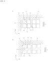
FIGS. 3A, 3B and 3C are views showing Example 1,FIG. 3A is an exploded view,FIG. 3B is a view showing a positional relationship between a magnetic pole member and a permanent magnet, andFIG. 3C is a view showing a state during assembly. -
FIG. 4A and 4B are views showing Example 2,FIG. 4A is a view showing a positional relationship between a magnetic pole member and a permanent magnet, andFIG. 4B is a view showing a final positional relationship between the magnetic pole member and the permanent magnet. -
FIG. 5 is a view showing another embodiment. -
FIG. 6 is a view showing another division mode of a magnetic pole member. -
FIG. 1 shows a plate PL of a magnetic clamp device provided with circular magnetic pole members. Cartesian coordinates X-axis, Y-axis are shown. A large number ofmagnet blocks 11 are arranged on a front surface of the plate PL. The plate PL is made of a magnetic body, and a large number ofcircular grooves 14 are provided on the front surface. Apart surrounded by agroove 14 corresponds to amagnet block 11. -
FIG. 1B is an exploded view taken along a line P-P inFIG. 1A . The Z-axis is orthogonal to the X-axis and the Y-axis, being a directional axis that extends from the front surface of the plate PL adsorbing the mold to the inside of the plate. In the figure, the plate PL is integrally provided with a portion D1 having a small thickness of steel on the Z-axis direction side of thegroove 14, and a disc-shaped portion D2 having a large thickness of steel further inside (functions as a pole member ). A cylindricalpermanent magnet 20 is inserted into the portion D1 having a small thickness of steel from the back side of the plate PL. Thepermanent magnet 20 has, for example, S pole on the inner peripheral side and N pole on the outer peripheral side of a ring which is an outer shape of the permanent magnet. For example, a neodymium magnet can be used as apermanent magnet 20. On the back side (Z-axis direction side) of thepermanent magnet 20, a reversible magnet 18 including a disc-shapedalnico magnet 16 and acoil 17 wound around the outside of thealnico magnet 16 is arranged. A disc-shaped cap 19 (magnetic body) is fitted into the plate PL from the back side (Z-axis direction side) of the reversible magnet 18. Eachmagnet block 11 includes a portion D2 functioning as a magnetic pole member, apermanent magnet 20, analnico magnet 16, acoil 17, and acap 19. The inner peripheral side of thepermanent magnet 20 is magnetically coupled to the portion D2, and magnetically coupled to the outer peripheral side (outer yoke D3) of the portion D1 having a reduced thickness on the outer peripheral side. The outer yoke D3 is fitted around the portion D2, thepermanent magnet 20, thealnico magnet 16, thecoil 17, and thecap 19. Thealnico magnet 16 is magnetically coupled to the portion D2 and thecap 19, and an outer peripheral surface of thecap 19 is magnetically coupled to an inner peripheral surface of the outer yoke D3. Further, the portion D4 of thegroove 14 is made thinner than the other parts, so that it is easily magnetically saturated. Since the front surface of the plate PL is entirely covered with steel of the plate PL, thepermanent magnet 20 and the reversible magnet 18 can be sealed from work area for mounting the mold M1. The magnetic clamp device is a mono-mag type magnetic clamp device in which the inner peripheral side of thepermanent magnet 20 is S pole and the outer peripheral side is N pole and a magnetic circuit is formed by onemagnetic block 11. -
FIG. 1C shows a state in which the magnetic clamp device is in a demagnetized state. Thealnico magnet 16 is a magnet in which the front side (the left side in the drawing) of the plate PL is N pole and the back side is S pole. Magnetic flux passes through a magnetic circuit formed by thepermanent magnet 20, the outer yoke D3, thecap 19, thealnico magnet 16, and the portion D2. In this state, the magnetic flux does not leak to the front surface of the plate PL, and the mold M1 is not adsorbed. -
FIG. 1D shows a state in which the magnetic clamp device is in a magnetized state. The magnetic pole of thealnico magnet 16 is reversed by applying a direct current to thecoil 17 from the outside. Thealnico magnet 16 is a magnet in which the front side of the plate PL is S pole and the back side thereof is N pole. The polarity of thealnico magnet 16 is reversed, and a direct current should be flowed for the time to hold the required magnetic flux. On the front surface side of the plate PL, both thepermanent magnet 20 and the reversible magnet 18 are coupled to the portion D2 as S pole. In a state in which the mold M1 is pressed against the front surface of the plate PL, these magnetic fluxes pass through the mold M1. As a result, a magnetic circuit composed of thepermanent magnet 20, the outer yoke D3, the mold M1 and the portion D2, and a magnetic circuit composed of thealnico magnet 16, the outer yoke D3, the mold M1 and the portion D2 are formed. When the mold M1 is lost, the magnetic force outward from the front surface of the plate PL is immediately lost by the magnetic force of thepermanent magnet 20 because thealnico magnet 16 does not relatively have high holding power as a permanent magnet. - Although the magnetic clamp device in
FIG. 1 is formed into a mono-mag type magnetic clamp device by arranging the inner side of thepermanent magnet 20 as S pole and the outer side thereof as N pole, a bi-mag type magnetic clamp device that forms a magnetic circuit with two adjacent magnet blocks can be configured if the inside of the permanent magnet 20' is inverted to N pole and the outside to S pole. -
FIG. 2 shows a magnetic clamp device provided with a square magnetic pole member. The X axis, the Y axis and the Z axis are defined in the same manner as inFIG. 1 .FIG. 2A is a plan view, andFIG. 2B is an exploded view of onemagnet block 11. The magnet blocks 11 are arranged adjacent to each other on the front surface of the plate PL. Themagnet block 11 includes amagnetic pole member 10, a plurality ofpermanent magnets 20 arranged on the outer peripheral side of themagnetic pole member 10, and analnico magnet 16 arranged on the rear surface side of themagnetic pole member 10. Themagnetic pole member 10 and thealnico magnet 16 are formed in a square shape. Thepermanent magnets 20 between the magnet blocks 11 adjacent to each other in the X-axis direction and the Y-axis direction are also used for both of these magnet blocks 11. Each of the magnet blocks 11 can be controlled into a magnetized state or a demagnetized state by thecoil 17 wound around thealnico magnet 16 as in the example inFIG. 1 . Themagnet block 11 is fixed to the plate PL by screwing a bolt 15 into a fixinghole 23 provided to the plate PL through a through hole 21 of themagnetic pole member 10 and a through hole 22 of thealnico magnet 16. - In the magnet blocks 11 in
FIGS. 1 and2 , the position of eachmagnet block 11 on the X axis and the Y axis is predetermined with respect to the plate PL. Thepermanent magnet 20 is arranged between themagnetic pole member 10 and the outer yoke D3, or between adjacentmagnetic pole member 10 andmagnetic pole members 10. It is necessary to design thepermanent magnet 20 to a slightly smaller size including an error so that it can be inserted around themagnetic pole member 10 without any trouble. This is because it is physically difficult to insert thepermanent magnet 20 if the dimensions are designed so that there is no gap for fitting with thepermanent magnet 20 in all directions around themagnetic pole member 10. On the other hand, direction of magnetic flux due to thepermanent magnet 20 is in a plane consisting of the X axis and the Y axis, and therefore, there is no choice but to make a magnetic circuit through the gap between themagnetic pole member 10 and thepermanent magnet 20 thus formed. - Examples of the present invention will be described below. The present invention aims to reduce the magnetic flux leaking from the magnetic circuit passing through the permanent magnet and the magnetic pole member, and will be described based on the following examples.
- Example 1 will be described below with reference to
FIG. 3 . Those having the same function as the reference numeral given inFIG. 1 are designated by the same numeral. Example 1 is an embodiment in which the present invention is applied to a magnetic clamp device provided with a circular magnetic pole member inFIG. 1 .FIG. 3A is an exploded view of amagnet block 11. The difference from themagnetic pole member 10 shown inFIG. 1 is in the structure of amagnetic pole member 10. In Example 1, themagnetic pole member 10 is divided into a plurality ofmagnetic pole pieces FIG. 1 , the portion D2 that is a part of the plate PL has a function as a magnetic pole member, but in Example 1, the function is divided into the portion that receives magnetic flux from a permanent magnet 20 (hereinafter referred to as a magnetic pole member 10) and the portion as the front surface of the plate PL (front surface portion D5). The front surface portion D5 is a magnetic pole plate that continuously covers themagnetic pole pieces magnetic pole member 10 is held between the front surface portion D5 and thealnico magnet 16 by restricting the Z-axis movement of themagnetic pole pieces - The
magnetic pole pieces magnetic pole pieces magnetic pole member 10 when they are assembled on a plane consisting of the X axis and the Y axis. In this example, it is circular. Themagnetic pole member 10 is radially divided from the center thereof at equal angular intervals. Each of themagnetic pole pieces magnetic pole member 10. This side surface (referred to as the first side surface R) is a curved surface that is as close to the inner diameter of thepermanent magnet 20 as the design allows, and thus, when the first side surface R is magnetically adsorbed to the inner peripheral surface of thepermanent magnet 20, there is almost no gap between the first side surface R and the inner peripheral surface of thepermanent magnet 20. On the other hand, the other side surface (referred to as the second side surface T) faces the side surface of another adjacent magnetic pole piece. InFIG. 3 , thepermanent magnet 20 is also divided into a plurality of arc-shapedpermanent magnet pieces -
FIG. 3B is a view showing a positional relationship between themagnetic pole member 10 and thepermanent magnet 20. Thepermanent magnet pieces permanent magnet 20 that is a combination of a plurality of magnets to form a cylindrical shape.FIG. 3C is a view showing an assembly process. The curvature radius of a curved surface of the permanent magnet piece is substantially the same as the inner diameter of the outer yoke D3, and dimensioned so as to minimize the gap due to the difference with the inner peripheral diameter of the outer yoke D3. When thepermanent magnet pieces - Next, when the
magnetic pole pieces permanent magnet 20, the first side surface R of each magnetic pole piece is adsorbed to and abutted by the opposing inner peripheral surfaces of thepermanent magnet 20 by a strong magnetic force. Since themagnetic pole pieces permanent magnet 20 is determined by the adsorption due to thepermanent magnet 20. Since the outer diameter of the arc of the permanent magnet piece is designed so as to substantially match the inner diameter of the outer yoke D3, themagnetic pole pieces permanent magnet 20 in a state that there is almost no gap. Therefore, the magnetic flux is hardly reduced due to the gaps between themagnetic pole pieces permanent magnet 20. When the pole pieces are adsorbed and moved, the second side surfaces T do not interfere with each other. Further, although a gap is formed between the second side surfaces T, no magnetic circuit is planned for the magnetic flux to cross this gap, so that it does not lead to an increase in magnetic resistance. A fixinghole 23 having a female screw is provided in the front surface portion D5, and thecap 19, thealnico magnet 16, and themagnetic pole member 10 are fixed to the front surface portion D5 from thecap 19 side with the bolt 15. Since the fixing in the Z-axis direction is made in close contact with each other by the bolt 15, the gap that interferes with the magnetic flux in the Z-axis direction is minimized. -
FIG. 4 is a view showing anembodiment 2. Those having the same functions as the reference numerals given inFIG. 2 are given the same reference numerals. This is an example in which the present invention is applied to a magnetic clamp device having the squaremagnetic pole member 10 ofFIG. 2 . Themagnetic pole member 10 is radially divided into fourmagnetic pole pieces FIG. 4A shows that thepermanent magnets 20 are arranged around themagnetic pole members 10.FIG. 4B shows the arrangement positions of thepermanent magnets 20 and thepole pieces magnetic pole pieces permanent magnets 20. In the present example, unlike Example 1, the contact surfaces of thepermanent magnet 20 and the first side surfaces R of themagnetic pole pieces permanent magnets 20, themagnetic pole pieces permanent magnets 20 arranged on the plate PL adsorb each of themagnetic pole pieces permanent magnets 20 and themagnetic pole pieces magnetic pole pieces magnetic pole pieces magnetic pole pieces -
FIG. 5 shows various structures for fixing thepermanent magnets 20, the magnetic pole members 10 (only themagnetic pole pieces magnetic pole pieces alnico magnets 16 on the plate PL. It should be noted that components having the same functions as the reference numerals given in other figures are given the same reference numerals.FIG. 5A shows a magnetic clamp device in which the front surface portion D5 corresponding to Example 1 is integrated with the plate PL. This is a bi-mag type magnetic clamp device in which the width of the outer yoke D3 is reduced so that the polarity of thepermanent magnet 20 is constructed in S pole on the inner peripheral side and N pole on the outer peripheral side, and so that the polarity of the permanent magnet 20' is constructed in N pole on the inner peripheral side and S pole on the outer peripheral side. -
FIG. 5B is different from the structure ofFIG. 5A in that the plate PL is divided into a front surface part PL-1 and a rear surface part PL-2 from the middle in the Z-axis direction. -
FIG. 5C shows almost the same as the structure ofFIG. 5A , except that the plate PL and thecap 19 are located opposite to each other on the front side and the back side in the Z-axis direction.FIG. 5C shows a form in which the front side and the back side ofFIG. 5A are opposite in the Z-axis direction. That is, thecap 19 is arranged on the front side, and a front surface member is arranged on the back side. The arrangement of the permanent magnet, the magnetic pole member and the alnico magnet is the same as the structure ofFIG. 5A . A seal is provided to isolate the permanent magnet from an environment on the front surface of the plate PL. -
FIG. 5D shows a structure in which caps 19a and 19b are provided on the front side and the back side in the structure ofFIG. 5C to sandwich thepermanent magnet 20, themagnetic pole member 10 and thealnico magnet 16. InFIG. 5E , the plate PL is divided into the front surface part PL-1 and the rear surface part PL-2 from the middle in the Z-axis direction so as to sandwich across the plurality ofpermanent magnets 20,magnetic pole members 10 andalnico magnets 16. As apparent fromFIGS. 5A to 5E , themagnetic pole member 10 is divided into themagnetic pole pieces 101 to 104 so as to move freely move. Therefore, when themagnetic pole member 10 is adsorbed to thepermanent magnet 20, its mechanical position needs to be fixed. In these examples, each magnetic pole piece is covered with one magnetic plate (in each example, thecap 19 or the plate PL has the function) from the Z-axis direction to be held mechanically between the magnetic plate and thealnico magnet 16. -
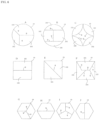
FIG. 6 shows another division form of themagnetic pole member 10.FIGS. 6A to 6C show examples of other division forms of the circularmagnetic pole member 10,FIGS. 6D to 6F show examples of other division forms of the squaremagnetic pole member 10, andFIGS. 6G to 6J show examples of division forms of polygonal magnetic pole member. With respect to the polygonalmagnetic pole member 10, the polygonalpermanent magnets 20 or a plurality of plate-shapedpermanent magnets 20 arranged in a polygonal shape surround the periphery of the magnetic pole member 10 (however, it is not shown). - In the division form of
FIG. 6A , the center of division is eccentric, and the size of eachpole piece FIG. 6B , the center of division is two places, and the size of eachpole piece FIG. 6C has a large defect part in the center. In each case, when themagnetic pole pieces permanent magnet 20, the second side surfaces divided by an inner dividing line Q of eachmagnetic pole piece magnetic pole pieces permanent magnet 20 without interfering with each other, respectively. - The division form of
FIG. 6D is formed by being divided in the middle of two sides of a square (left and right opposite sides in the figure). In this configuration, thepermanent magnet 20 is closely contacted up and down only, and may not be closely contacted left to right.FIG. 6E shows a form of division by an inner division line Q passing through corners of a square.FIG. 6F shows a form of division by an inner division line Q passing through corners of a square as inFIG. 6E . In any of the forms, the second side surfaces divided by the inner division line Q of each magnetic pole piece are oriented away from each other, and the magnetic pole pieces are adsorbed to thepermanent magnet 20 without interfering with each other. The inner division lines Q need only be set so that the second side surfaces do not interfere with each other when the magnetic pole pieces are adsorbed to thepermanent magnet 20, so that the inner division lines Q may be divided so that the defect part occurs in themagnetic pole member 10. - The division forms of
FIGS. 6G and 6H are formed by being divided by inner division lines Q passing through the vertices of a polygon. The division forms ofFIGS. 6I and 6J are formed by being divided by inner division lines Q passing through the middle of a side of a polygon. In any of the forms, the second side surfaces divided by the inner division lines Q of each magnetic pole piece are separated from each other, and the magnetic pole pieces are adsorbed to thepermanent magnet 20 without interfering with each other. - Although the
caps 19, 19a, and 19b are magnetic bodies that connect the magnetic circuit between thealnico magnet 16 and the outer yoke D3, the outer peripheral surfaces of thecaps 19, 19a, 19b in the above mentioned examples are magnetically coupled to the inner peripheral surfaces of the outer yoke D3. On the other hand, also in the fitting of thecaps 19, 19a, 19b and the outer yoke D3, it is necessary to previously provide gaps for fitting. Therefore, in order to make the gaps for fitting as small as possible, thecaps 19, 19a and 19b may be divided into a plurality of divided pieces after the shapes of thecaps 19, 19a and 19b are made as close as possible to the shape of the inner peripheral surface of the outer yoke D3 as in the divided form of eachmagnetic pole member 10 shown inFIG. 3 ,FIG. 4 , andFIG. 6 . When themagnetic pole members 10 ofFIG. 3 ,FIG. 4 , andFIG. 6 are regarded as thecaps 19, 19a, and 19b, and themagnetic pole pieces caps 19, 19a, and 19b is defined as a third side surface, and side surfaces facing the side surfaces of another adjacent divided piece can be defined as fourth side surfaces. When the divided pieces of thecaps 19, 19a, and 19b form a magnetic circuit between thealnico magnet 16 and the outer yoke D3, the fourth side surfaces of the divided pieces are separated from each other and the third side surfaces are adsorbed to the outer yoke D3. - Each divided piece of the
caps 19, 19a, and 19b is fixed by pouring resin into each gap of the fourth side surfaces or pressing from behind after each third side surface is adsorbed to the outer yoke D3. -
- 10 magnetic member
- 11 magnet block
- 14 groove
- 15 bolt
- 16 alnico magnet
- 17 coil
- 18 reversible magnet
- 19 cap
- 19a, 19b cap
- 20 permanent magnet
- 21 through hole
- 22 through hole
- 23 fixing hole
- 101, 102, 103, 104 magnetic pole piece
- 201, 202, 203, 204 permanent magnet piece
Claims (4)
- A magnetic clamp device having a plate (PL) made of a magnetic body for magnetically clamping a mold (M1) on a front side of said plate, a permanent magnet (20) disposed so as to surround a magnetic pole member (10), and a reversible magnet (16, 17) capable of reversing polarity on a back side of said plate,wherein said magnetic pole member (10) is constituted by a plurality of separate magnetic pole pieces (101 to 104), each of said magnetic pole pieces having a first lateral surface (R) with a shape corresponding to said permanent magnet (20) and a second lateral surface (T) at which adjacent magnetic pole pieces oppose each other,
second lateral surfaces of said adjacent magnetic pole pieces being arranged with a gap therebetween, and said first lateral surface being in contact with said permanent magnet, andsaid magnetic pole pieces are held from the front side and the back side of the plate. - The magnetic clamp device according to claim 1, wherein a magnetic plate (D5) for continuously covering each magnetic member is provided on the front sides of the plurality of magnetic pole pieces, and the plurality of magnetic pole pieces (101 to 104) are held between the reversible magnets (16, 17) and the magnetic plate.
- The magnetic clamp device according to claim 1 or 2, wherein the permanent magnet (20) has a plurality of magnetic pole pieces (201 to 204) surrounding a periphery of the magnetic pole member (10).
- The magnetic clamp device according to one of claims 1 to 3, further comprising:a cap (19) of a magnetic body provided behind the reversible magnet, andan outer yoke (D3) for externally fitting a periphery of said cap,wherein said cap is constituted by a plurality of divided pieces, each divided piece having a third side surface in a shape corresponding to facing outer yoke and a fourth side surface which adjacent divided pieces face oppose each other, andwherein fourth side surfaces of adjacent divided pieces are arranged with a gap therebetween, and the third side surfaces are in contact with the outer yoke.
Applications Claiming Priority (2)
| Application Number | Priority Date | Filing Date | Title |
|---|---|---|---|
| JP2018132370A JP7088546B2 (en) | 2018-07-12 | 2018-07-12 | Magnetic clamp device |
| PCT/JP2019/021664 WO2020012819A1 (en) | 2018-07-12 | 2019-05-31 | Magnetic clamp device |
Publications (3)
| Publication Number | Publication Date |
|---|---|
| EP3782788A1 EP3782788A1 (en) | 2021-02-24 |
| EP3782788A4 EP3782788A4 (en) | 2021-06-30 |
| EP3782788B1 true EP3782788B1 (en) | 2023-04-19 |
Family
ID=69141406
Family Applications (1)
| Application Number | Title | Priority Date | Filing Date |
|---|---|---|---|
| EP19833294.2A Active EP3782788B1 (en) | 2018-07-12 | 2019-05-31 | Magnetic clamp device |
Country Status (5)
| Country | Link |
|---|---|
| US (1) | US11869711B2 (en) |
| EP (1) | EP3782788B1 (en) |
| JP (1) | JP7088546B2 (en) |
| CN (1) | CN112334289B (en) |
| WO (1) | WO2020012819A1 (en) |
Families Citing this family (3)
| Publication number | Priority date | Publication date | Assignee | Title |
|---|---|---|---|---|
| US11923135B2 (en) * | 2019-08-29 | 2024-03-05 | Kosmek Ltd. | Magnetic clamp device |
| JP7687675B2 (en) * | 2021-09-28 | 2025-06-03 | 株式会社コスメック | Magnetic Clamping Device |
| DE102023110830B3 (en) * | 2023-04-27 | 2024-04-18 | Airbus Defence and Space GmbH | Panel, mounting structure, aircraft and opening device |
Family Cites Families (17)
| Publication number | Priority date | Publication date | Assignee | Title |
|---|---|---|---|---|
| US4401960A (en) * | 1979-12-18 | 1983-08-30 | Kanetsu Kogyo Kabushiki Kaisha | Magnet assembly |
| JPS5859368U (en) * | 1981-10-15 | 1983-04-21 | 住友特殊金属株式会社 | Magnetic circuit for DC motor |
| JP3164219B2 (en) * | 1996-01-30 | 2001-05-08 | 愛知製鋼株式会社 | Magnetic pole dispersion opposed magnetic attachment |
| JP4428692B2 (en) * | 2003-12-11 | 2010-03-10 | パスカルエンジニアリング株式会社 | Mold fixing device for injection molding machine |
| JP2005246634A (en) * | 2004-03-01 | 2005-09-15 | Tomita:Kk | Mold fixing device for injection molding machine |
| WO2008105042A1 (en) * | 2007-02-23 | 2008-09-04 | Pascal Engineering Corporation | Die securing system |
| JP5385544B2 (en) * | 2008-04-02 | 2014-01-08 | パスカルエンジニアリング株式会社 | Magnetic fixing device |
| WO2010021013A1 (en) * | 2008-08-21 | 2010-02-25 | パスカルエンジニアリング株式会社 | Metal mold adherence detector for injection molding machine |
| JP2012148378A (en) * | 2011-01-20 | 2012-08-09 | Pascal Engineering Corp | Clamping device |
| JP6031341B2 (en) * | 2012-11-30 | 2016-11-24 | 株式会社ナベヤ | Magnetic adsorption device |
| US10024437B2 (en) * | 2014-05-13 | 2018-07-17 | EagleBurgmann Japan Co., Ltd. | Assembly method of magnetic fluid seal and magnetic fluid seal |
| ITUB20154095A1 (en) * | 2015-10-01 | 2017-04-01 | S P D S P A | MAGNETIC SYSTEM |
| JP6722463B2 (en) * | 2016-01-08 | 2020-07-15 | 株式会社コスメック | Magnet clamp system |
| JP6670628B2 (en) | 2016-02-18 | 2020-03-25 | 株式会社ナベヤ | Magnetic adsorption device |
| JP6775798B2 (en) * | 2016-09-12 | 2020-10-28 | 株式会社コスメック | Mold mounting method |
| CN112154044A (en) * | 2018-02-23 | 2020-12-29 | 磁转换技术全球私人有限公司 | Variable field magnetic coupler and method for joining ferromagnetic workpieces |
| JP7420381B2 (en) * | 2020-10-14 | 2024-01-23 | カネテック株式会社 | magnet holder |
-
2018
- 2018-07-12 JP JP2018132370A patent/JP7088546B2/en active Active
-
2019
- 2019-05-31 CN CN201980042476.2A patent/CN112334289B/en active Active
- 2019-05-31 EP EP19833294.2A patent/EP3782788B1/en active Active
- 2019-05-31 US US17/257,441 patent/US11869711B2/en active Active
- 2019-05-31 WO PCT/JP2019/021664 patent/WO2020012819A1/en not_active Ceased
Also Published As
| Publication number | Publication date |
|---|---|
| CN112334289A (en) | 2021-02-05 |
| JP2020006658A (en) | 2020-01-16 |
| US20210183554A1 (en) | 2021-06-17 |
| US11869711B2 (en) | 2024-01-09 |
| EP3782788A1 (en) | 2021-02-24 |
| CN112334289B (en) | 2022-08-02 |
| EP3782788A4 (en) | 2021-06-30 |
| WO2020012819A1 (en) | 2020-01-16 |
| JP7088546B2 (en) | 2022-06-21 |
Similar Documents
| Publication | Publication Date | Title |
|---|---|---|
| US11869711B2 (en) | Magnetic clamp device | |
| KR101812079B1 (en) | Linear actuator | |
| JP5426116B2 (en) | Magnetic clamp device | |
| US7154199B2 (en) | Driving apparatus for moving member to be moved | |
| TWI279525B (en) | Actuator with position detecting mechanism | |
| US8292276B2 (en) | One-piece multipole plate for a magnetic holding apparatus, process for making such plate and magnetic apparatus using such plate | |
| KR101131134B1 (en) | A permanent magnet workholding device | |
| TW201636151A (en) | Electromagnetic chuck | |
| TW201512572A (en) | Electromagnetic valve | |
| JP2016029880A (en) | Magnet unit and method of manufacturing magnet unit | |
| US9903500B2 (en) | Electromagnetic valve | |
| JP2011193641A (en) | Linear motor and method for manufacturing reciprocating rod | |
| US20220277876A1 (en) | Magnetic clamp device | |
| JP3217116U (en) | Magnetic adsorption device | |
| JP2018099738A (en) | Magnetic clamping device | |
| US9647524B2 (en) | Linear actuator | |
| JP6670628B2 (en) | Magnetic adsorption device | |
| US20190362875A1 (en) | Electromagnetic linear actuator | |
| WO2024048184A1 (en) | Motor | |
| US10317697B2 (en) | Actuator and lens barrel with actuator | |
| CN209373237U (en) | Optical component support device and driving device, photographic means and electronic equipment | |
| JP2017213650A (en) | Permanent electromagnetic type magnetic attraction device | |
| JP7680748B2 (en) | Magnetic Adsorption Device | |
| JP2518717Y2 (en) | Magnetic fluid shaft seal device | |
| JPH0752450Y2 (en) | Magnetic fluid seal device for bearings |
Legal Events
| Date | Code | Title | Description |
|---|---|---|---|
| STAA | Information on the status of an ep patent application or granted ep patent |
Free format text: STATUS: THE INTERNATIONAL PUBLICATION HAS BEEN MADE |
|
| PUAI | Public reference made under article 153(3) epc to a published international application that has entered the european phase |
Free format text: ORIGINAL CODE: 0009012 |
|
| STAA | Information on the status of an ep patent application or granted ep patent |
Free format text: STATUS: REQUEST FOR EXAMINATION WAS MADE |
|
| 17P | Request for examination filed |
Effective date: 20201117 |
|
| AK | Designated contracting states |
Kind code of ref document: A1 Designated state(s): AL AT BE BG CH CY CZ DE DK EE ES FI FR GB GR HR HU IE IS IT LI LT LU LV MC MK MT NL NO PL PT RO RS SE SI SK SM TR |
|
| AX | Request for extension of the european patent |
Extension state: BA ME |
|
| A4 | Supplementary search report drawn up and despatched |
Effective date: 20210602 |
|
| RIC1 | Information provided on ipc code assigned before grant |
Ipc: B29C 33/32 20060101AFI20210527BHEP Ipc: B23Q 3/15 20060101ALI20210527BHEP Ipc: H01F 7/02 20060101ALI20210527BHEP |
|
| DAV | Request for validation of the european patent (deleted) | ||
| DAX | Request for extension of the european patent (deleted) | ||
| GRAP | Despatch of communication of intention to grant a patent |
Free format text: ORIGINAL CODE: EPIDOSNIGR1 |
|
| STAA | Information on the status of an ep patent application or granted ep patent |
Free format text: STATUS: GRANT OF PATENT IS INTENDED |
|
| INTG | Intention to grant announced |
Effective date: 20230105 |
|
| GRAS | Grant fee paid |
Free format text: ORIGINAL CODE: EPIDOSNIGR3 |
|
| GRAA | (expected) grant |
Free format text: ORIGINAL CODE: 0009210 |
|
| STAA | Information on the status of an ep patent application or granted ep patent |
Free format text: STATUS: THE PATENT HAS BEEN GRANTED |
|
| AK | Designated contracting states |
Kind code of ref document: B1 Designated state(s): AL AT BE BG CH CY CZ DE DK EE ES FI FR GB GR HR HU IE IS IT LI LT LU LV MC MK MT NL NO PL PT RO RS SE SI SK SM TR |
|
| REG | Reference to a national code |
Ref country code: GB Ref legal event code: FG4D |
|
| REG | Reference to a national code |
Ref country code: DE Ref legal event code: R096 Ref document number: 602019027858 Country of ref document: DE |
|
| REG | Reference to a national code |
Ref country code: CH Ref legal event code: EP |
|
| REG | Reference to a national code |
Ref country code: IE Ref legal event code: FG4D |
|
| REG | Reference to a national code |
Ref country code: AT Ref legal event code: REF Ref document number: 1560856 Country of ref document: AT Kind code of ref document: T Effective date: 20230515 |
|
| REG | Reference to a national code |
Ref country code: LT Ref legal event code: MG9D |
|
| REG | Reference to a national code |
Ref country code: NL Ref legal event code: MP Effective date: 20230419 |
|
| REG | Reference to a national code |
Ref country code: AT Ref legal event code: MK05 Ref document number: 1560856 Country of ref document: AT Kind code of ref document: T Effective date: 20230419 |
|
| PG25 | Lapsed in a contracting state [announced via postgrant information from national office to epo] |
Ref country code: NL Free format text: LAPSE BECAUSE OF FAILURE TO SUBMIT A TRANSLATION OF THE DESCRIPTION OR TO PAY THE FEE WITHIN THE PRESCRIBED TIME-LIMIT Effective date: 20230419 |
|
| PG25 | Lapsed in a contracting state [announced via postgrant information from national office to epo] |
Ref country code: SE Free format text: LAPSE BECAUSE OF FAILURE TO SUBMIT A TRANSLATION OF THE DESCRIPTION OR TO PAY THE FEE WITHIN THE PRESCRIBED TIME-LIMIT Effective date: 20230419 Ref country code: PT Free format text: LAPSE BECAUSE OF FAILURE TO SUBMIT A TRANSLATION OF THE DESCRIPTION OR TO PAY THE FEE WITHIN THE PRESCRIBED TIME-LIMIT Effective date: 20230821 Ref country code: NO Free format text: LAPSE BECAUSE OF FAILURE TO SUBMIT A TRANSLATION OF THE DESCRIPTION OR TO PAY THE FEE WITHIN THE PRESCRIBED TIME-LIMIT Effective date: 20230719 Ref country code: ES Free format text: LAPSE BECAUSE OF FAILURE TO SUBMIT A TRANSLATION OF THE DESCRIPTION OR TO PAY THE FEE WITHIN THE PRESCRIBED TIME-LIMIT Effective date: 20230419 Ref country code: AT Free format text: LAPSE BECAUSE OF FAILURE TO SUBMIT A TRANSLATION OF THE DESCRIPTION OR TO PAY THE FEE WITHIN THE PRESCRIBED TIME-LIMIT Effective date: 20230419 |
|
| PG25 | Lapsed in a contracting state [announced via postgrant information from national office to epo] |
Ref country code: RS Free format text: LAPSE BECAUSE OF FAILURE TO SUBMIT A TRANSLATION OF THE DESCRIPTION OR TO PAY THE FEE WITHIN THE PRESCRIBED TIME-LIMIT Effective date: 20230419 Ref country code: PL Free format text: LAPSE BECAUSE OF FAILURE TO SUBMIT A TRANSLATION OF THE DESCRIPTION OR TO PAY THE FEE WITHIN THE PRESCRIBED TIME-LIMIT Effective date: 20230419 Ref country code: LV Free format text: LAPSE BECAUSE OF FAILURE TO SUBMIT A TRANSLATION OF THE DESCRIPTION OR TO PAY THE FEE WITHIN THE PRESCRIBED TIME-LIMIT Effective date: 20230419 Ref country code: LT Free format text: LAPSE BECAUSE OF FAILURE TO SUBMIT A TRANSLATION OF THE DESCRIPTION OR TO PAY THE FEE WITHIN THE PRESCRIBED TIME-LIMIT Effective date: 20230419 Ref country code: IS Free format text: LAPSE BECAUSE OF FAILURE TO SUBMIT A TRANSLATION OF THE DESCRIPTION OR TO PAY THE FEE WITHIN THE PRESCRIBED TIME-LIMIT Effective date: 20230819 Ref country code: HR Free format text: LAPSE BECAUSE OF FAILURE TO SUBMIT A TRANSLATION OF THE DESCRIPTION OR TO PAY THE FEE WITHIN THE PRESCRIBED TIME-LIMIT Effective date: 20230419 Ref country code: GR Free format text: LAPSE BECAUSE OF FAILURE TO SUBMIT A TRANSLATION OF THE DESCRIPTION OR TO PAY THE FEE WITHIN THE PRESCRIBED TIME-LIMIT Effective date: 20230720 Ref country code: AL Free format text: LAPSE BECAUSE OF FAILURE TO SUBMIT A TRANSLATION OF THE DESCRIPTION OR TO PAY THE FEE WITHIN THE PRESCRIBED TIME-LIMIT Effective date: 20230419 |
|
| PG25 | Lapsed in a contracting state [announced via postgrant information from national office to epo] |
Ref country code: FI Free format text: LAPSE BECAUSE OF FAILURE TO SUBMIT A TRANSLATION OF THE DESCRIPTION OR TO PAY THE FEE WITHIN THE PRESCRIBED TIME-LIMIT Effective date: 20230419 |
|
| REG | Reference to a national code |
Ref country code: CH Ref legal event code: PL |
|
| PG25 | Lapsed in a contracting state [announced via postgrant information from national office to epo] |
Ref country code: SK Free format text: LAPSE BECAUSE OF FAILURE TO SUBMIT A TRANSLATION OF THE DESCRIPTION OR TO PAY THE FEE WITHIN THE PRESCRIBED TIME-LIMIT Effective date: 20230419 |
|
| PG25 | Lapsed in a contracting state [announced via postgrant information from national office to epo] |
Ref country code: MC Free format text: LAPSE BECAUSE OF FAILURE TO SUBMIT A TRANSLATION OF THE DESCRIPTION OR TO PAY THE FEE WITHIN THE PRESCRIBED TIME-LIMIT Effective date: 20230419 |
|
| REG | Reference to a national code |
Ref country code: DE Ref legal event code: R097 Ref document number: 602019027858 Country of ref document: DE |
|
| REG | Reference to a national code |
Ref country code: BE Ref legal event code: MM Effective date: 20230531 |
|
| PG25 | Lapsed in a contracting state [announced via postgrant information from national office to epo] |
Ref country code: SM Free format text: LAPSE BECAUSE OF FAILURE TO SUBMIT A TRANSLATION OF THE DESCRIPTION OR TO PAY THE FEE WITHIN THE PRESCRIBED TIME-LIMIT Effective date: 20230419 Ref country code: SK Free format text: LAPSE BECAUSE OF FAILURE TO SUBMIT A TRANSLATION OF THE DESCRIPTION OR TO PAY THE FEE WITHIN THE PRESCRIBED TIME-LIMIT Effective date: 20230419 Ref country code: RO Free format text: LAPSE BECAUSE OF FAILURE TO SUBMIT A TRANSLATION OF THE DESCRIPTION OR TO PAY THE FEE WITHIN THE PRESCRIBED TIME-LIMIT Effective date: 20230419 Ref country code: MC Free format text: LAPSE BECAUSE OF FAILURE TO SUBMIT A TRANSLATION OF THE DESCRIPTION OR TO PAY THE FEE WITHIN THE PRESCRIBED TIME-LIMIT Effective date: 20230419 Ref country code: LU Free format text: LAPSE BECAUSE OF NON-PAYMENT OF DUE FEES Effective date: 20230531 Ref country code: LI Free format text: LAPSE BECAUSE OF NON-PAYMENT OF DUE FEES Effective date: 20230531 Ref country code: EE Free format text: LAPSE BECAUSE OF FAILURE TO SUBMIT A TRANSLATION OF THE DESCRIPTION OR TO PAY THE FEE WITHIN THE PRESCRIBED TIME-LIMIT Effective date: 20230419 Ref country code: DK Free format text: LAPSE BECAUSE OF FAILURE TO SUBMIT A TRANSLATION OF THE DESCRIPTION OR TO PAY THE FEE WITHIN THE PRESCRIBED TIME-LIMIT Effective date: 20230419 Ref country code: CZ Free format text: LAPSE BECAUSE OF FAILURE TO SUBMIT A TRANSLATION OF THE DESCRIPTION OR TO PAY THE FEE WITHIN THE PRESCRIBED TIME-LIMIT Effective date: 20230419 Ref country code: CH Free format text: LAPSE BECAUSE OF NON-PAYMENT OF DUE FEES Effective date: 20230531 |
|
| PLBE | No opposition filed within time limit |
Free format text: ORIGINAL CODE: 0009261 |
|
| STAA | Information on the status of an ep patent application or granted ep patent |
Free format text: STATUS: NO OPPOSITION FILED WITHIN TIME LIMIT |
|
| REG | Reference to a national code |
Ref country code: IE Ref legal event code: MM4A |
|
| 26N | No opposition filed |
Effective date: 20240122 |
|
| GBPC | Gb: european patent ceased through non-payment of renewal fee |
Effective date: 20230719 |
|
| PG25 | Lapsed in a contracting state [announced via postgrant information from national office to epo] |
Ref country code: IE Free format text: LAPSE BECAUSE OF NON-PAYMENT OF DUE FEES Effective date: 20230531 |
|
| PG25 | Lapsed in a contracting state [announced via postgrant information from national office to epo] |
Ref country code: IE Free format text: LAPSE BECAUSE OF NON-PAYMENT OF DUE FEES Effective date: 20230531 Ref country code: GB Free format text: LAPSE BECAUSE OF NON-PAYMENT OF DUE FEES Effective date: 20230719 |
|
| PG25 | Lapsed in a contracting state [announced via postgrant information from national office to epo] |
Ref country code: SI Free format text: LAPSE BECAUSE OF FAILURE TO SUBMIT A TRANSLATION OF THE DESCRIPTION OR TO PAY THE FEE WITHIN THE PRESCRIBED TIME-LIMIT Effective date: 20230419 |
|
| PG25 | Lapsed in a contracting state [announced via postgrant information from national office to epo] |
Ref country code: SI Free format text: LAPSE BECAUSE OF FAILURE TO SUBMIT A TRANSLATION OF THE DESCRIPTION OR TO PAY THE FEE WITHIN THE PRESCRIBED TIME-LIMIT Effective date: 20230419 Ref country code: BE Free format text: LAPSE BECAUSE OF NON-PAYMENT OF DUE FEES Effective date: 20230531 |
|
| PG25 | Lapsed in a contracting state [announced via postgrant information from national office to epo] |
Ref country code: BG Free format text: LAPSE BECAUSE OF FAILURE TO SUBMIT A TRANSLATION OF THE DESCRIPTION OR TO PAY THE FEE WITHIN THE PRESCRIBED TIME-LIMIT Effective date: 20230419 |
|
| PG25 | Lapsed in a contracting state [announced via postgrant information from national office to epo] |
Ref country code: BG Free format text: LAPSE BECAUSE OF FAILURE TO SUBMIT A TRANSLATION OF THE DESCRIPTION OR TO PAY THE FEE WITHIN THE PRESCRIBED TIME-LIMIT Effective date: 20230419 |
|
| PG25 | Lapsed in a contracting state [announced via postgrant information from national office to epo] |
Ref country code: CY Free format text: LAPSE BECAUSE OF FAILURE TO SUBMIT A TRANSLATION OF THE DESCRIPTION OR TO PAY THE FEE WITHIN THE PRESCRIBED TIME-LIMIT; INVALID AB INITIO Effective date: 20190531 |
|
| PG25 | Lapsed in a contracting state [announced via postgrant information from national office to epo] |
Ref country code: HU Free format text: LAPSE BECAUSE OF FAILURE TO SUBMIT A TRANSLATION OF THE DESCRIPTION OR TO PAY THE FEE WITHIN THE PRESCRIBED TIME-LIMIT; INVALID AB INITIO Effective date: 20190531 |
|
| PG25 | Lapsed in a contracting state [announced via postgrant information from national office to epo] |
Ref country code: TR Free format text: LAPSE BECAUSE OF FAILURE TO SUBMIT A TRANSLATION OF THE DESCRIPTION OR TO PAY THE FEE WITHIN THE PRESCRIBED TIME-LIMIT Effective date: 20230419 |
|
| PGFP | Annual fee paid to national office [announced via postgrant information from national office to epo] |
Ref country code: IT Payment date: 20260525 Year of fee payment: 8 |
|
| PGFP | Annual fee paid to national office [announced via postgrant information from national office to epo] |
Ref country code: DE Payment date: 20260522 Year of fee payment: 8 |
|
| PGFP | Annual fee paid to national office [announced via postgrant information from national office to epo] |
Ref country code: FR Payment date: 20260526 Year of fee payment: 8 |