EP3782759A1 - Apparatus for arc welding and method of using the same - Google Patents
Apparatus for arc welding and method of using the same Download PDFInfo
- Publication number
- EP3782759A1 EP3782759A1 EP19212063.2A EP19212063A EP3782759A1 EP 3782759 A1 EP3782759 A1 EP 3782759A1 EP 19212063 A EP19212063 A EP 19212063A EP 3782759 A1 EP3782759 A1 EP 3782759A1
- Authority
- EP
- European Patent Office
- Prior art keywords
- metal segments
- gas
- elongated objects
- welding
- arc welding
- Prior art date
- Legal status (The legal status is an assumption and is not a legal conclusion. Google has not performed a legal analysis and makes no representation as to the accuracy of the status listed.)
- Granted
Links
Images


Classifications
-
- B—PERFORMING OPERATIONS; TRANSPORTING
- B23—MACHINE TOOLS; METAL-WORKING NOT OTHERWISE PROVIDED FOR
- B23K—SOLDERING OR UNSOLDERING; WELDING; CLADDING OR PLATING BY SOLDERING OR WELDING; CUTTING BY APPLYING HEAT LOCALLY, e.g. FLAME CUTTING; WORKING BY LASER BEAM
- B23K9/00—Arc welding or cutting
- B23K9/16—Arc welding or cutting making use of shielding gas
- B23K9/164—Arc welding or cutting making use of shielding gas making use of a moving fluid
-
- B—PERFORMING OPERATIONS; TRANSPORTING
- B23—MACHINE TOOLS; METAL-WORKING NOT OTHERWISE PROVIDED FOR
- B23K—SOLDERING OR UNSOLDERING; WELDING; CLADDING OR PLATING BY SOLDERING OR WELDING; CUTTING BY APPLYING HEAT LOCALLY, e.g. FLAME CUTTING; WORKING BY LASER BEAM
- B23K9/00—Arc welding or cutting
- B23K9/02—Seam welding; Backing means; Inserts
- B23K9/028—Seam welding; Backing means; Inserts for curved planar seams
-
- B—PERFORMING OPERATIONS; TRANSPORTING
- B23—MACHINE TOOLS; METAL-WORKING NOT OTHERWISE PROVIDED FOR
- B23K—SOLDERING OR UNSOLDERING; WELDING; CLADDING OR PLATING BY SOLDERING OR WELDING; CUTTING BY APPLYING HEAT LOCALLY, e.g. FLAME CUTTING; WORKING BY LASER BEAM
- B23K9/00—Arc welding or cutting
- B23K9/16—Arc welding or cutting making use of shielding gas
- B23K9/167—Arc welding or cutting making use of shielding gas and of a non-consumable electrode
-
- B—PERFORMING OPERATIONS; TRANSPORTING
- B23—MACHINE TOOLS; METAL-WORKING NOT OTHERWISE PROVIDED FOR
- B23K—SOLDERING OR UNSOLDERING; WELDING; CLADDING OR PLATING BY SOLDERING OR WELDING; CUTTING BY APPLYING HEAT LOCALLY, e.g. FLAME CUTTING; WORKING BY LASER BEAM
- B23K11/00—Resistance welding; Severing by resistance heating
- B23K11/04—Flash butt welding
- B23K11/046—Apparatus therefor
-
- B—PERFORMING OPERATIONS; TRANSPORTING
- B23—MACHINE TOOLS; METAL-WORKING NOT OTHERWISE PROVIDED FOR
- B23K—SOLDERING OR UNSOLDERING; WELDING; CLADDING OR PLATING BY SOLDERING OR WELDING; CUTTING BY APPLYING HEAT LOCALLY, e.g. FLAME CUTTING; WORKING BY LASER BEAM
- B23K35/00—Rods, electrodes, materials, or media, for use in soldering, welding, or cutting
- B23K35/22—Rods, electrodes, materials, or media, for use in soldering, welding, or cutting characterised by the composition or nature of the material
- B23K35/222—Non-consumable electrodes
-
- B—PERFORMING OPERATIONS; TRANSPORTING
- B23—MACHINE TOOLS; METAL-WORKING NOT OTHERWISE PROVIDED FOR
- B23K—SOLDERING OR UNSOLDERING; WELDING; CLADDING OR PLATING BY SOLDERING OR WELDING; CUTTING BY APPLYING HEAT LOCALLY, e.g. FLAME CUTTING; WORKING BY LASER BEAM
- B23K37/00—Auxiliary devices or processes, not specially adapted for a procedure covered by only one of the other main groups of this subclass
- B23K37/04—Auxiliary devices or processes, not specially adapted for a procedure covered by only one of the other main groups of this subclass for holding or positioning work
-
- B—PERFORMING OPERATIONS; TRANSPORTING
- B23—MACHINE TOOLS; METAL-WORKING NOT OTHERWISE PROVIDED FOR
- B23K—SOLDERING OR UNSOLDERING; WELDING; CLADDING OR PLATING BY SOLDERING OR WELDING; CUTTING BY APPLYING HEAT LOCALLY, e.g. FLAME CUTTING; WORKING BY LASER BEAM
- B23K9/00—Arc welding or cutting
- B23K9/0026—Arc welding or cutting specially adapted for particular articles or work
-
- B—PERFORMING OPERATIONS; TRANSPORTING
- B23—MACHINE TOOLS; METAL-WORKING NOT OTHERWISE PROVIDED FOR
- B23K—SOLDERING OR UNSOLDERING; WELDING; CLADDING OR PLATING BY SOLDERING OR WELDING; CUTTING BY APPLYING HEAT LOCALLY, e.g. FLAME CUTTING; WORKING BY LASER BEAM
- B23K9/00—Arc welding or cutting
- B23K9/16—Arc welding or cutting making use of shielding gas
- B23K9/167—Arc welding or cutting making use of shielding gas and of a non-consumable electrode
- B23K9/1675—Arc welding or cutting making use of shielding gas and of a non-consumable electrode making use of several electrodes
-
- B—PERFORMING OPERATIONS; TRANSPORTING
- B23—MACHINE TOOLS; METAL-WORKING NOT OTHERWISE PROVIDED FOR
- B23K—SOLDERING OR UNSOLDERING; WELDING; CLADDING OR PLATING BY SOLDERING OR WELDING; CUTTING BY APPLYING HEAT LOCALLY, e.g. FLAME CUTTING; WORKING BY LASER BEAM
- B23K9/00—Arc welding or cutting
- B23K9/24—Features related to electrodes
- B23K9/28—Supporting devices for electrodes
- B23K9/29—Supporting devices adapted for making use of shielding means
- B23K9/291—Supporting devices adapted for making use of shielding means the shielding means being a gas
- B23K9/296—Supporting devices adapted for making use of shielding means the shielding means being a gas using non-consumable electrodes
Definitions
- Exemplary embodiments pertain to the art of arc welding, and more particularly, to an apparatus for gas tungsten arc welding and methods of using the same.
- Gas tungsten arc welding is a welding process in which an electric arc forms between a non-consumable metal electrode and the workpiece metal(s), which heats the workpiece metal(s), causing them to melt and join.
- a shielding gas feeds through the welding torch, which shields the process from contaminants in the atmosphere.
- a constant current, direct current power source is most often used, but constant voltage systems, as well as alternating current, can be used as well.
- Arc welding via a singular, localized electrode often involves significant rotation, e.g., rotation of the welding apparatus itself and/or the object being welded, in order to complete a given welding task. Accordingly, significant time and skill is also needed to complete said welding task.
- an apparatus for arc welding comprising: a torch body comprising a power supply line and a gas supply line; two or more metal segments movable relative to one another being sized and shaped to surround a seam between two elongated objects to be welded together, the two or more metal segments being in electrical communication with the power supply line; and a gas jacket attached to each of the metal segments.
- Also disclosed is a method of arc welding using the apparatus comprising: moving the metal segments relative to one another to surround the seam between the two elongated objects to be welded; passing shielding gas through the gas jacket; applying an electric current to the metal segments, thereby creating an electrical arc between the metal segments and the two elongated objects to be welded.
- an apparatus 10 for arc welding comprises a torch body 12.
- the torch body 12 can comprise a power supply line 14 and a gas supply line 16.
- the power supply line 14 can run through the torch body 12.
- the as supply line 16 can also run through the torch body 12.
- the apparatus 10 for arc welding comprises two or more metal segments 18.
- the metal segments 18 act as electrodes in the arc welding apparatus 10.
- the metal segments 18 can be separate and distinct from each other. Together the metal segments 18 can form an elliptical or polygonal shape, for example, a circle, oval, square, or triangle shape.
- metal segments 18 can be curved, for example, the curved metal segments 18 can be formed by taking a circular, ring-like piece of metal and breaking it up into the two or more distinct curved metal segments 18.
- the metal segments 18 can different from each other in size and shape, or alternatively, the metal segments 18 can be equal to each other in size and shape.
- the apparatus 10 comprises three metal segments 18. In one embodiment, the apparatus 10 comprises four metal segments 18.
- the metal segments 18 can comprise any suitable alloy metal electrode for gas tungsten arc welding, for example, the metal segments 18 can comprise any tungsten alloy. Adjacent metal segments 18 can be spaced about 1 millimeter to about 100 millimeters apart depending on the size of the desired welding object(s), for example, about 5 millimeters to about 15 millimeters apart, for example, about 5 millimeters to 10 millimeters apart.
- the metal segments 18 are movable relative to one another, for example, movable in a radial direction 20.
- the elliptical or polygonal shape formed by the metal segments 18 can expand and/or contract creating a larger or smaller elliptical or polygonal shape as needed to fit a desired welding object(s) 28.
- the metal segments 18 can be movable relative to one another, being sized and shaped to surround a seam 29 between two elongated objects 28 to be welded together.
- the metal segments 18 can be adjusted in a radial direction via a screw mechanism.
- the metal segments can be adjusted in a radial direction via a leadscrew, for example, a mechanical guided leadscrew.
- the apparatus 10 can further comprise a locking mechanism 26 located between two or more adjacent metal segments 18. The locking mechanism can maintain a given position of the metal segments 18.
- An electric current 22 can be in communication with the power supply line 14 and the metal segments 18, for example, the electric current 22 can run through the torch body 12 from the power supply line 14 to the metal segments 18.
- the electric current can be a direct current or an alternating current.
- the apparatus 10 for arc welding can comprise a gas jacket 24 attached to each of the metal segments 18.
- the gas jacket 24 can also surround and seal the seam 29 between the welding objects 28.
- the gas jacket 24 thereby allows control of the welding environment.
- the apparatus 10 can comprise a shielding gas in communication with the gas supply line 16 and the gas jacket 24, for example, the shielding gas can run through the torch body 12 from the gas supply line 16 to the gas jacket 24, passing through the gas jacket 24.
- Shielding gas protects the welding area from atmospheric gases such as nitrogen and oxygen, which can cause fusion defects, porosity, and weld metal embrittlement if they come in contact with the welding object 28.
- the shielding gas can be an inert gas, an active gas, or a combination thereof.
- the shielding gas can be helium, neon, argon, krypton, xenon, radon, or a combination thereof.
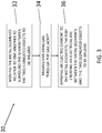
- a method 30 for arc welding comprises step 32: moving the metal segments 18 relative to one another to surround the seam 29 between the two elongated objects 28 to be welded.
- the method 30 for arc welding further comprises step 34: passing shielding gas through the gas jacket 24, for example, via the gas supply line 16.
- the method 30 for arc welding further comprises step 36: applying an electric current 22 to the metal segments 18, thereby creating an electrical arc 25 between the metal segments 18 and the two elongated objects 28 to be welded.
- the electrical arc 25 can be created between the welding objects 28 and all of the curved metal segments 18 simultaneously.
- the application of the electrical arc 25 to the welding objects 28, at the seam 29, is what accomplishes the welding of the objects 28 together.
- the electrical arc 25 can fully surround the seam 29 between the two welding objects 28 (as seen in FIG. 1 ), thereby allowing welding to occur fully around the seam 29 all at once.
- Welding of the welding objects 28 can be completed in less than or equal to 10 seconds, for example, less than or equal to 5 seconds, for example, less than or equal to 3 seconds depending on the size of the seam 29 and/or the welding objects 28.
- the method 30 for arc welding may or may not comprise rotation of the metal segments 18 via rotation of the torch body 12.
- the method 30 for arc welding does not comprise rotation of the welding objects 28. Accordingly, an apparatus for gas tungsten arc welding, and methods of using the same, as disclosed herein, reduce both the time and skill involved in arc welding.
Landscapes
- Engineering & Computer Science (AREA)
- Mechanical Engineering (AREA)
- Physics & Mathematics (AREA)
- Plasma & Fusion (AREA)
- Optics & Photonics (AREA)
- Arc Welding In General (AREA)
Abstract
Description
- Exemplary embodiments pertain to the art of arc welding, and more particularly, to an apparatus for gas tungsten arc welding and methods of using the same.
- Gas tungsten arc welding is a welding process in which an electric arc forms between a non-consumable metal electrode and the workpiece metal(s), which heats the workpiece metal(s), causing them to melt and join. Along with the electrode, a shielding gas feeds through the welding torch, which shields the process from contaminants in the atmosphere. A constant current, direct current power source is most often used, but constant voltage systems, as well as alternating current, can be used as well.
- Arc welding via a singular, localized electrode often involves significant rotation, e.g., rotation of the welding apparatus itself and/or the object being welded, in order to complete a given welding task. Accordingly, significant time and skill is also needed to complete said welding task.
- Therefore, there is a need to develop an apparatus for gas tungsten arc welding, and methods of using the same, which reduce both the time and skill involved in arc welding.
- Disclosed is an apparatus for arc welding, comprising: a torch body comprising a power supply line and a gas supply line; two or more metal segments movable relative to one another being sized and shaped to surround a seam between two elongated objects to be welded together, the two or more metal segments being in electrical communication with the power supply line; and a gas jacket attached to each of the metal segments.
- Also disclosed is a method of arc welding using the apparatus, the method comprising: moving the metal segments relative to one another to surround the seam between the two elongated objects to be welded; passing shielding gas through the gas jacket; applying an electric current to the metal segments, thereby creating an electrical arc between the metal segments and the two elongated objects to be welded.
- The following descriptions should not be considered limiting in any way. With reference to the accompanying drawings, like elements are numbered alike:
-
FIG. 1 is a simplified diagram of an apparatus for arc welding according to an exemplary embodiment; -
FIG. 2 is a simplified diagram of two elongated objects to be welded according to an exemplary embodiment; and -
FIG. 3 is a method flow chart for a method of arc welding according to an exemplary embodiment. - A detailed description of one or more embodiments of the disclosed apparatus and method are presented herein by way of exemplification and not limitation with reference to the Figures.
- Referring to
FIG. 1 , anapparatus 10 for arc welding, according to one embodiment, comprises atorch body 12. For example, thetorch body 12 can comprise apower supply line 14 and agas supply line 16. For example, thepower supply line 14 can run through thetorch body 12. The assupply line 16 can also run through thetorch body 12. - The
apparatus 10 for arc welding, according to one embodiment, comprises two ormore metal segments 18. Themetal segments 18 act as electrodes in thearc welding apparatus 10. Themetal segments 18 can be separate and distinct from each other. Together themetal segments 18 can form an elliptical or polygonal shape, for example, a circle, oval, square, or triangle shape. In one embodiment,metal segments 18 can be curved, for example, thecurved metal segments 18 can be formed by taking a circular, ring-like piece of metal and breaking it up into the two or more distinctcurved metal segments 18. Themetal segments 18 can different from each other in size and shape, or alternatively, themetal segments 18 can be equal to each other in size and shape. In one embodiment, theapparatus 10 comprises threemetal segments 18. In one embodiment, theapparatus 10 comprises fourmetal segments 18. Themetal segments 18 can comprise any suitable alloy metal electrode for gas tungsten arc welding, for example, themetal segments 18 can comprise any tungsten alloy.Adjacent metal segments 18 can be spaced about 1 millimeter to about 100 millimeters apart depending on the size of the desired welding object(s), for example, about 5 millimeters to about 15 millimeters apart, for example, about 5 millimeters to 10 millimeters apart. - The
metal segments 18 are movable relative to one another, for example, movable in aradial direction 20. For example, as themetal segments 18 move in a radial direction, the elliptical or polygonal shape formed by themetal segments 18 can expand and/or contract creating a larger or smaller elliptical or polygonal shape as needed to fit a desired welding object(s) 28. For example, referring toFIG. 2 , themetal segments 18 can be movable relative to one another, being sized and shaped to surround aseam 29 between twoelongated objects 28 to be welded together. - In one embodiment, the
metal segments 18 can be adjusted in a radial direction via a screw mechanism. For example, the metal segments can be adjusted in a radial direction via a leadscrew, for example, a mechanical guided leadscrew. Theapparatus 10 can further comprise alocking mechanism 26 located between two or moreadjacent metal segments 18. The locking mechanism can maintain a given position of themetal segments 18. - An
electric current 22 can be in communication with thepower supply line 14 and themetal segments 18, for example, theelectric current 22 can run through thetorch body 12 from thepower supply line 14 to themetal segments 18. The electric current can be a direct current or an alternating current. - The
apparatus 10 for arc welding, according to one embodiment, can comprise agas jacket 24 attached to each of themetal segments 18. Thegas jacket 24 can also surround and seal theseam 29 between thewelding objects 28. Thegas jacket 24 thereby allows control of the welding environment. Theapparatus 10 can comprise a shielding gas in communication with thegas supply line 16 and thegas jacket 24, for example, the shielding gas can run through thetorch body 12 from thegas supply line 16 to thegas jacket 24, passing through thegas jacket 24. Shielding gas protects the welding area from atmospheric gases such as nitrogen and oxygen, which can cause fusion defects, porosity, and weld metal embrittlement if they come in contact with thewelding object 28. The shielding gas can be an inert gas, an active gas, or a combination thereof. For example, the shielding gas can be helium, neon, argon, krypton, xenon, radon, or a combination thereof. - Referring to
FIG. 3 , amethod 30 for arc welding, according to one embodiment, comprises step 32: moving themetal segments 18 relative to one another to surround theseam 29 between the twoelongated objects 28 to be welded. - The
method 30 for arc welding further comprises step 34: passing shielding gas through thegas jacket 24, for example, via thegas supply line 16. - The
method 30 for arc welding further comprises step 36: applying anelectric current 22 to themetal segments 18, thereby creating anelectrical arc 25 between themetal segments 18 and the twoelongated objects 28 to be welded. For example, theelectrical arc 25 can be created between thewelding objects 28 and all of thecurved metal segments 18 simultaneously. The application of theelectrical arc 25 to thewelding objects 28, at theseam 29, is what accomplishes the welding of theobjects 28 together. In an embodiment, theelectrical arc 25 can fully surround theseam 29 between the two welding objects 28 (as seen inFIG. 1 ), thereby allowing welding to occur fully around theseam 29 all at once. - Welding of the
welding objects 28 can be completed in less than or equal to 10 seconds, for example, less than or equal to 5 seconds, for example, less than or equal to 3 seconds depending on the size of theseam 29 and/or thewelding objects 28. In one embodiment, themethod 30 for arc welding may or may not comprise rotation of themetal segments 18 via rotation of thetorch body 12. In another embodiment, themethod 30 for arc welding does not comprise rotation of thewelding objects 28. Accordingly, an apparatus for gas tungsten arc welding, and methods of using the same, as disclosed herein, reduce both the time and skill involved in arc welding. - The term "about" is intended to include the degree of error associated with measurement of the particular quantity based upon the equipment available at the time of filing the application.
- The terminology used herein is for the purpose of describing particular embodiments only and is not intended to be limiting of the present disclosure. As used herein, the singular forms "a", "an" and "the" are intended to include the plural forms as well, unless the context clearly indicates otherwise. It will be further understood that the terms "comprises" and/or "comprising," when used in this specification, specify the presence of stated features, integers, steps, operations, elements, and/or components, but do not preclude the presence or addition of one or more other features, integers, steps, operations, element components, and/or groups thereof.
- While the present disclosure has been described with reference to an exemplary embodiment or embodiments, it will be understood by those skilled in the art that various changes may be made and equivalents may be substituted for elements thereof without departing from the scope of the invention as defined by the claims. In addition, many modifications may be made to adapt a particular situation or material to the teachings of the present disclosure without departing from the scope of the invention. Therefore, it is intended that the present disclosure not be limited to the particular embodiment disclosed as the best mode contemplated for carrying out this present disclosure, but that the present disclosure will include all embodiments falling within the scope of the claims.
Claims (15)
- An apparatus for arc welding, comprising:a torch body (12) comprising a power supply line (14) and a gas supply line (16);two or more metal segments (18) movable relative to one another being sized and shaped to surround a seam (29) between two elongated objects (28) to be welded together, the two or more metal segments being in electrical communication with the power supply line; anda gas jacket (24) attached to each of the metal segments.
- The apparatus of Claim 1, further comprising a shielding gas in communication with the gas supply line and the gas jacket, wherein the shielding gas is an inert gas, an active gas, or a combination thereof.
- The apparatus of Claim 2, wherein the shielding gas is helium, neon, argon, krypton, xenon, radon, or a combination thereof.
- The apparatus of Claim 1, 2 or 3 wherein the metal segments are equal to each other in size and shape.
- The apparatus of any preceding Claim, wherein the apparatus comprises three metal segments, or wherein the apparatus comprises four metal segments.
- The apparatus of any preceding Claim, wherein the metal segments are curved and together the metal segments form an elliptical shape.
- The apparatus of any preceding Claim, wherein the metal segments comprise tungsten, tungsten alloy, or a combination thereof.
- The apparatus of any preceding Claim, wherein the metal segments are moveable in a radial direction (20) via a screw mechanism or wherein the metal segments are moveable in a radial direction via a leadscrew.
- The apparatus of any preceding Claim, further comprising a locking mechanism located between two or more adjacent metal segments.
- The apparatus of any preceding Claim, wherein adjacent metal segments are spaced about 1 millimeter to about 100 millimeters apart.
- A method of arc welding using the apparatus of any preceding Claim, the method comprising:moving the metal segments relative to one another to surround the seam between the two elongated objects to be welded;passing shielding gas through the gas jacket;applying an electric current to the metal segments, thereby creating an electrical arc between the metal segments and the two elongated objects to be welded.
- The method of arc welding of Claim 11, wherein the method does not comprise rotation of the two elongated objects to be welded, or wherein the method comprises rotation of the metal segments via rotation of the torch body.
- The method of arc welding of Claim 11 or 12, wherein welding of the two elongated objects is completed in less than or equal to 10 seconds, or wherein welding of the two elongated objects is completed is less than or equal to 5 seconds or wherein welding of the two elongated objects is completed is less than or equal to 3 seconds.
- The method of arc welding of Claim 11, 12 or 13, wherein the electrical arc is created between the two elongated objects to be welded and all of the metal segments simultaneously.
- The method of arc welding of any of Claims 11 to 14, wherein the electrical arc fully surrounds the seam between the two elongated objects to be welded.
Applications Claiming Priority (1)
| Application Number | Priority Date | Filing Date | Title |
|---|---|---|---|
| IN201911033678 | 2019-08-21 |
Publications (2)
| Publication Number | Publication Date |
|---|---|
| EP3782759A1 true EP3782759A1 (en) | 2021-02-24 |
| EP3782759B1 EP3782759B1 (en) | 2024-03-13 |
Family
ID=68731794
Family Applications (1)
| Application Number | Title | Priority Date | Filing Date |
|---|---|---|---|
| EP19212063.2A Active EP3782759B1 (en) | 2019-08-21 | 2019-11-28 | Apparatus for arc welding and method of using the same |
Country Status (3)
| Country | Link |
|---|---|
| US (1) | US11597024B2 (en) |
| EP (1) | EP3782759B1 (en) |
| CA (1) | CA3064227A1 (en) |
Citations (4)
| Publication number | Priority date | Publication date | Assignee | Title |
|---|---|---|---|---|
| DE3613706C1 (en) * | 1986-04-23 | 1987-04-09 | Steinmueller Gmbh L & C | Method of welding a stud to a metallic parent body, apparatus for carrying out the method, and stud for use during the method |
| US5841089A (en) * | 1997-07-14 | 1998-11-24 | Astro Arc Polysoude, Incorporated | Small size tube welding apparatus |
| US6380505B1 (en) * | 2000-03-27 | 2002-04-30 | The Boeing Company | Method and apparatus for welding tubular members |
| US20060076320A1 (en) * | 2004-10-13 | 2006-04-13 | Babcock-Hitachi Kabushiki Kaisha | Non-consumable electrode welding torch and welding head with the torch |
Family Cites Families (15)
| Publication number | Priority date | Publication date | Assignee | Title |
|---|---|---|---|---|
| DE1527593B2 (en) * | 1964-09-03 | 1971-02-25 | Siemens AG, 1000 Berlin u 8000 München | Device for the deformation of cylindrical workpieces made of metal by the impulse-like action of a magnetic field |
| US4243868A (en) | 1979-05-02 | 1981-01-06 | General Atomic Company | Orbital arc-welding apparatus of split construction |
| US4372474A (en) * | 1980-11-28 | 1983-02-08 | Dimetrics, Inc. | Full function in-place weld head |
| US4803339A (en) | 1987-09-16 | 1989-02-07 | Rockwell International Corporation | Hollow electrode and arc initiation method |
| US4810848A (en) * | 1987-11-06 | 1989-03-07 | Gasparas Kazlauskas | Tube welder |
| US4841115A (en) * | 1988-02-25 | 1989-06-20 | St International | Orbital weldhead |
| US5440090A (en) | 1993-06-07 | 1995-08-08 | Atlantic Richfield Company | Duplex stainless steel welding method |
| DE4436615A1 (en) * | 1994-10-13 | 1996-04-18 | Steingroever Magnet Physik | Magnetic forming of metal workpieces at high efficiency |
| US5686002A (en) | 1996-08-12 | 1997-11-11 | Tri Tool Inc. | Method of welding |
| US5710403A (en) | 1996-10-15 | 1998-01-20 | Jusionis; Vytautas John | Orbital weldhead with integral cooling |
| US7170032B2 (en) | 2003-11-20 | 2007-01-30 | Tri Tool Inc. | Process for welding |
| US9950394B2 (en) | 2012-03-12 | 2018-04-24 | Hobart Brothers Company | Systems and methods for welding electrodes |
| EP3055101A2 (en) | 2013-10-09 | 2016-08-17 | Hobart Brothers Company | Systems and methods for corrosion-resistant welding electrodes |
| KR101615918B1 (en) | 2015-04-07 | 2016-04-27 | 두산중공업 주식회사 | The welding method with double-head |
| CN205428680U (en) | 2015-08-31 | 2016-08-03 | 比亚迪股份有限公司 | Stator that slot insulation that electrical resolver used and electrical resolver used |
-
2019
- 2019-10-17 US US16/655,753 patent/US11597024B2/en active Active
- 2019-11-28 EP EP19212063.2A patent/EP3782759B1/en active Active
- 2019-12-06 CA CA3064227A patent/CA3064227A1/en active Pending
Patent Citations (4)
| Publication number | Priority date | Publication date | Assignee | Title |
|---|---|---|---|---|
| DE3613706C1 (en) * | 1986-04-23 | 1987-04-09 | Steinmueller Gmbh L & C | Method of welding a stud to a metallic parent body, apparatus for carrying out the method, and stud for use during the method |
| US5841089A (en) * | 1997-07-14 | 1998-11-24 | Astro Arc Polysoude, Incorporated | Small size tube welding apparatus |
| US6380505B1 (en) * | 2000-03-27 | 2002-04-30 | The Boeing Company | Method and apparatus for welding tubular members |
| US20060076320A1 (en) * | 2004-10-13 | 2006-04-13 | Babcock-Hitachi Kabushiki Kaisha | Non-consumable electrode welding torch and welding head with the torch |
Non-Patent Citations (1)
| Title |
|---|
| ZÃ1?4RN H: "WIG-Schutzgasschwelà en mit Mehrlachkathodenanordnung", SCHWEIà EN UND SCHNEIDEN,, vol. 18, no. 5, 1 May 1966 (1966-05-01), pages 237, XP001341098 * |
Also Published As
| Publication number | Publication date |
|---|---|
| US20210053133A1 (en) | 2021-02-25 |
| BR102019026043A2 (en) | 2021-02-23 |
| US11597024B2 (en) | 2023-03-07 |
| CA3064227A1 (en) | 2021-02-21 |
| EP3782759B1 (en) | 2024-03-13 |
Similar Documents
| Publication | Publication Date | Title |
|---|---|---|
| KR100504296B1 (en) | Method of welding | |
| JP3208808U (en) | A system that provides position feedback for additive manufacturing | |
| KR102452174B1 (en) | Systems and methods providing location feedback for additive manufacturing | |
| US20150165540A1 (en) | System and Method for True Electrode Speed | |
| US10369668B2 (en) | Welding system | |
| US20150027997A1 (en) | Welding torch, welding apparatus and method of welding using hollow electrode and filler material | |
| EP4257277A3 (en) | Systems, methods, and apparatus to control welding electrode preheating | |
| JP2019107698A (en) | System and method for providing position feedback for additional manufacture | |
| EP3782759B1 (en) | Apparatus for arc welding and method of using the same | |
| ES2006912A6 (en) | Gas tungsten arc welding machine with infinite rotating welding head and torch tilt. | |
| JP2018024019A (en) | Process and apparatus for welding workpiece having heat sensitive material | |
| CN108025384B (en) | System and method for reducing weld root pockets | |
| WO2004022277A1 (en) | Method for metallurgically capping an end of a tube | |
| CN112334262A (en) | Spot welding machine | |
| US6870120B2 (en) | Welding torch | |
| BR102019026043B1 (en) | ARC WELDING DEVICE | |
| EP3575028A1 (en) | Method for processing insulator and foreign object, and device for same | |
| US20230051339A1 (en) | Shear stud welding system | |
| US11224911B2 (en) | Barrel tank seam welder system | |
| CA3127975A1 (en) | Shear stud welding system | |
| NL1024169C2 (en) | Welding device and welding torch. | |
| KR200483142Y1 (en) | The assist device for supply of electrode | |
| JP2020040080A (en) | Electrode position adjustment mechanism of spot welder | |
| US20210023639A1 (en) | Method and system for pipeline welding | |
| US4556778A (en) | Arc welding at high part speeds |
Legal Events
| Date | Code | Title | Description |
|---|---|---|---|
| PUAI | Public reference made under article 153(3) epc to a published international application that has entered the european phase |
Free format text: ORIGINAL CODE: 0009012 |
|
| STAA | Information on the status of an ep patent application or granted ep patent |
Free format text: STATUS: THE APPLICATION HAS BEEN PUBLISHED |
|
| AK | Designated contracting states |
Kind code of ref document: A1 Designated state(s): AL AT BE BG CH CY CZ DE DK EE ES FI FR GB GR HR HU IE IS IT LI LT LU LV MC MK MT NL NO PL PT RO RS SE SI SK SM TR |
|
| AX | Request for extension of the european patent |
Extension state: BA ME |
|
| STAA | Information on the status of an ep patent application or granted ep patent |
Free format text: STATUS: REQUEST FOR EXAMINATION WAS MADE |
|
| 17P | Request for examination filed |
Effective date: 20210824 |
|
| RBV | Designated contracting states (corrected) |
Designated state(s): AL AT BE BG CH CY CZ DE DK EE ES FI FR GB GR HR HU IE IS IT LI LT LU LV MC MK MT NL NO PL PT RO RS SE SI SK SM TR |
|
| GRAP | Despatch of communication of intention to grant a patent |
Free format text: ORIGINAL CODE: EPIDOSNIGR1 |
|
| STAA | Information on the status of an ep patent application or granted ep patent |
Free format text: STATUS: GRANT OF PATENT IS INTENDED |
|
| INTG | Intention to grant announced |
Effective date: 20231115 |
|
| GRAS | Grant fee paid |
Free format text: ORIGINAL CODE: EPIDOSNIGR3 |
|
| GRAA | (expected) grant |
Free format text: ORIGINAL CODE: 0009210 |
|
| STAA | Information on the status of an ep patent application or granted ep patent |
Free format text: STATUS: THE PATENT HAS BEEN GRANTED |
|
| AK | Designated contracting states |
Kind code of ref document: B1 Designated state(s): AL AT BE BG CH CY CZ DE DK EE ES FI FR GB GR HR HU IE IS IT LI LT LU LV MC MK MT NL NO PL PT RO RS SE SI SK SM TR |
|
| REG | Reference to a national code |
Ref country code: GB Ref legal event code: FG4D |
|
| REG | Reference to a national code |
Ref country code: CH Ref legal event code: EP |
|
| REG | Reference to a national code |
Ref country code: DE Ref legal event code: R096 Ref document number: 602019048132 Country of ref document: DE |
|
| REG | Reference to a national code |
Ref country code: IE Ref legal event code: FG4D |
|
| PG25 | Lapsed in a contracting state [announced via postgrant information from national office to epo] |
Ref country code: LT Free format text: LAPSE BECAUSE OF FAILURE TO SUBMIT A TRANSLATION OF THE DESCRIPTION OR TO PAY THE FEE WITHIN THE PRESCRIBED TIME-LIMIT Effective date: 20240313 |
|
| REG | Reference to a national code |
Ref country code: LT Ref legal event code: MG9D |
|
| PG25 | Lapsed in a contracting state [announced via postgrant information from national office to epo] |
Ref country code: GR Free format text: LAPSE BECAUSE OF FAILURE TO SUBMIT A TRANSLATION OF THE DESCRIPTION OR TO PAY THE FEE WITHIN THE PRESCRIBED TIME-LIMIT Effective date: 20240614 |
|
| REG | Reference to a national code |
Ref country code: NL Ref legal event code: MP Effective date: 20240313 |
|
| PG25 | Lapsed in a contracting state [announced via postgrant information from national office to epo] |
Ref country code: RS Free format text: LAPSE BECAUSE OF FAILURE TO SUBMIT A TRANSLATION OF THE DESCRIPTION OR TO PAY THE FEE WITHIN THE PRESCRIBED TIME-LIMIT Effective date: 20240613 Ref country code: HR Free format text: LAPSE BECAUSE OF FAILURE TO SUBMIT A TRANSLATION OF THE DESCRIPTION OR TO PAY THE FEE WITHIN THE PRESCRIBED TIME-LIMIT Effective date: 20240313 |
|
| PG25 | Lapsed in a contracting state [announced via postgrant information from national office to epo] |
Ref country code: ES Free format text: LAPSE BECAUSE OF FAILURE TO SUBMIT A TRANSLATION OF THE DESCRIPTION OR TO PAY THE FEE WITHIN THE PRESCRIBED TIME-LIMIT Effective date: 20240313 |
|
| PG25 | Lapsed in a contracting state [announced via postgrant information from national office to epo] |
Ref country code: RS Free format text: LAPSE BECAUSE OF FAILURE TO SUBMIT A TRANSLATION OF THE DESCRIPTION OR TO PAY THE FEE WITHIN THE PRESCRIBED TIME-LIMIT Effective date: 20240613 Ref country code: NO Free format text: LAPSE BECAUSE OF FAILURE TO SUBMIT A TRANSLATION OF THE DESCRIPTION OR TO PAY THE FEE WITHIN THE PRESCRIBED TIME-LIMIT Effective date: 20240613 Ref country code: LT Free format text: LAPSE BECAUSE OF FAILURE TO SUBMIT A TRANSLATION OF THE DESCRIPTION OR TO PAY THE FEE WITHIN THE PRESCRIBED TIME-LIMIT Effective date: 20240313 Ref country code: HR Free format text: LAPSE BECAUSE OF FAILURE TO SUBMIT A TRANSLATION OF THE DESCRIPTION OR TO PAY THE FEE WITHIN THE PRESCRIBED TIME-LIMIT Effective date: 20240313 Ref country code: GR Free format text: LAPSE BECAUSE OF FAILURE TO SUBMIT A TRANSLATION OF THE DESCRIPTION OR TO PAY THE FEE WITHIN THE PRESCRIBED TIME-LIMIT Effective date: 20240614 Ref country code: FI Free format text: LAPSE BECAUSE OF FAILURE TO SUBMIT A TRANSLATION OF THE DESCRIPTION OR TO PAY THE FEE WITHIN THE PRESCRIBED TIME-LIMIT Effective date: 20240313 Ref country code: ES Free format text: LAPSE BECAUSE OF FAILURE TO SUBMIT A TRANSLATION OF THE DESCRIPTION OR TO PAY THE FEE WITHIN THE PRESCRIBED TIME-LIMIT Effective date: 20240313 Ref country code: BG Free format text: LAPSE BECAUSE OF FAILURE TO SUBMIT A TRANSLATION OF THE DESCRIPTION OR TO PAY THE FEE WITHIN THE PRESCRIBED TIME-LIMIT Effective date: 20240313 |
|
| REG | Reference to a national code |
Ref country code: AT Ref legal event code: MK05 Ref document number: 1665289 Country of ref document: AT Kind code of ref document: T Effective date: 20240313 |
|
| PG25 | Lapsed in a contracting state [announced via postgrant information from national office to epo] |
Ref country code: SE Free format text: LAPSE BECAUSE OF FAILURE TO SUBMIT A TRANSLATION OF THE DESCRIPTION OR TO PAY THE FEE WITHIN THE PRESCRIBED TIME-LIMIT Effective date: 20240313 Ref country code: LV Free format text: LAPSE BECAUSE OF FAILURE TO SUBMIT A TRANSLATION OF THE DESCRIPTION OR TO PAY THE FEE WITHIN THE PRESCRIBED TIME-LIMIT Effective date: 20240313 |
|
| PG25 | Lapsed in a contracting state [announced via postgrant information from national office to epo] |
Ref country code: NL Free format text: LAPSE BECAUSE OF FAILURE TO SUBMIT A TRANSLATION OF THE DESCRIPTION OR TO PAY THE FEE WITHIN THE PRESCRIBED TIME-LIMIT Effective date: 20240313 |
|
| PG25 | Lapsed in a contracting state [announced via postgrant information from national office to epo] |
Ref country code: NL Free format text: LAPSE BECAUSE OF FAILURE TO SUBMIT A TRANSLATION OF THE DESCRIPTION OR TO PAY THE FEE WITHIN THE PRESCRIBED TIME-LIMIT Effective date: 20240313 |
|
| PG25 | Lapsed in a contracting state [announced via postgrant information from national office to epo] |
Ref country code: IS Free format text: LAPSE BECAUSE OF FAILURE TO SUBMIT A TRANSLATION OF THE DESCRIPTION OR TO PAY THE FEE WITHIN THE PRESCRIBED TIME-LIMIT Effective date: 20240713 |
|
| PG25 | Lapsed in a contracting state [announced via postgrant information from national office to epo] |
Ref country code: PT Free format text: LAPSE BECAUSE OF FAILURE TO SUBMIT A TRANSLATION OF THE DESCRIPTION OR TO PAY THE FEE WITHIN THE PRESCRIBED TIME-LIMIT Effective date: 20240715 Ref country code: SM Free format text: LAPSE BECAUSE OF FAILURE TO SUBMIT A TRANSLATION OF THE DESCRIPTION OR TO PAY THE FEE WITHIN THE PRESCRIBED TIME-LIMIT Effective date: 20240313 |
|
| PG25 | Lapsed in a contracting state [announced via postgrant information from national office to epo] |
Ref country code: EE Free format text: LAPSE BECAUSE OF FAILURE TO SUBMIT A TRANSLATION OF THE DESCRIPTION OR TO PAY THE FEE WITHIN THE PRESCRIBED TIME-LIMIT Effective date: 20240313 Ref country code: CZ Free format text: LAPSE BECAUSE OF FAILURE TO SUBMIT A TRANSLATION OF THE DESCRIPTION OR TO PAY THE FEE WITHIN THE PRESCRIBED TIME-LIMIT Effective date: 20240313 |
|
| PG25 | Lapsed in a contracting state [announced via postgrant information from national office to epo] |
Ref country code: AT Free format text: LAPSE BECAUSE OF FAILURE TO SUBMIT A TRANSLATION OF THE DESCRIPTION OR TO PAY THE FEE WITHIN THE PRESCRIBED TIME-LIMIT Effective date: 20240313 |
|
| PG25 | Lapsed in a contracting state [announced via postgrant information from national office to epo] |
Ref country code: PL Free format text: LAPSE BECAUSE OF FAILURE TO SUBMIT A TRANSLATION OF THE DESCRIPTION OR TO PAY THE FEE WITHIN THE PRESCRIBED TIME-LIMIT Effective date: 20240313 |
|
| PG25 | Lapsed in a contracting state [announced via postgrant information from national office to epo] |
Ref country code: SK Free format text: LAPSE BECAUSE OF FAILURE TO SUBMIT A TRANSLATION OF THE DESCRIPTION OR TO PAY THE FEE WITHIN THE PRESCRIBED TIME-LIMIT Effective date: 20240313 |
|
| PG25 | Lapsed in a contracting state [announced via postgrant information from national office to epo] |
Ref country code: SM Free format text: LAPSE BECAUSE OF FAILURE TO SUBMIT A TRANSLATION OF THE DESCRIPTION OR TO PAY THE FEE WITHIN THE PRESCRIBED TIME-LIMIT Effective date: 20240313 Ref country code: SK Free format text: LAPSE BECAUSE OF FAILURE TO SUBMIT A TRANSLATION OF THE DESCRIPTION OR TO PAY THE FEE WITHIN THE PRESCRIBED TIME-LIMIT Effective date: 20240313 Ref country code: RO Free format text: LAPSE BECAUSE OF FAILURE TO SUBMIT A TRANSLATION OF THE DESCRIPTION OR TO PAY THE FEE WITHIN THE PRESCRIBED TIME-LIMIT Effective date: 20240313 Ref country code: PT Free format text: LAPSE BECAUSE OF FAILURE TO SUBMIT A TRANSLATION OF THE DESCRIPTION OR TO PAY THE FEE WITHIN THE PRESCRIBED TIME-LIMIT Effective date: 20240715 Ref country code: PL Free format text: LAPSE BECAUSE OF FAILURE TO SUBMIT A TRANSLATION OF THE DESCRIPTION OR TO PAY THE FEE WITHIN THE PRESCRIBED TIME-LIMIT Effective date: 20240313 Ref country code: IS Free format text: LAPSE BECAUSE OF FAILURE TO SUBMIT A TRANSLATION OF THE DESCRIPTION OR TO PAY THE FEE WITHIN THE PRESCRIBED TIME-LIMIT Effective date: 20240713 Ref country code: EE Free format text: LAPSE BECAUSE OF FAILURE TO SUBMIT A TRANSLATION OF THE DESCRIPTION OR TO PAY THE FEE WITHIN THE PRESCRIBED TIME-LIMIT Effective date: 20240313 Ref country code: CZ Free format text: LAPSE BECAUSE OF FAILURE TO SUBMIT A TRANSLATION OF THE DESCRIPTION OR TO PAY THE FEE WITHIN THE PRESCRIBED TIME-LIMIT Effective date: 20240313 Ref country code: AT Free format text: LAPSE BECAUSE OF FAILURE TO SUBMIT A TRANSLATION OF THE DESCRIPTION OR TO PAY THE FEE WITHIN THE PRESCRIBED TIME-LIMIT Effective date: 20240313 |
|
| PG25 | Lapsed in a contracting state [announced via postgrant information from national office to epo] |
Ref country code: IT Free format text: LAPSE BECAUSE OF FAILURE TO SUBMIT A TRANSLATION OF THE DESCRIPTION OR TO PAY THE FEE WITHIN THE PRESCRIBED TIME-LIMIT Effective date: 20240313 |
|
| REG | Reference to a national code |
Ref country code: DE Ref legal event code: R097 Ref document number: 602019048132 Country of ref document: DE |
|
| PG25 | Lapsed in a contracting state [announced via postgrant information from national office to epo] |
Ref country code: IT Free format text: LAPSE BECAUSE OF FAILURE TO SUBMIT A TRANSLATION OF THE DESCRIPTION OR TO PAY THE FEE WITHIN THE PRESCRIBED TIME-LIMIT Effective date: 20240313 |
|
| PG25 | Lapsed in a contracting state [announced via postgrant information from national office to epo] |
Ref country code: DK Free format text: LAPSE BECAUSE OF FAILURE TO SUBMIT A TRANSLATION OF THE DESCRIPTION OR TO PAY THE FEE WITHIN THE PRESCRIBED TIME-LIMIT Effective date: 20240313 |
|
| PLBE | No opposition filed within time limit |
Free format text: ORIGINAL CODE: 0009261 |
|
| STAA | Information on the status of an ep patent application or granted ep patent |
Free format text: STATUS: NO OPPOSITION FILED WITHIN TIME LIMIT |
|
| PG25 | Lapsed in a contracting state [announced via postgrant information from national office to epo] |
Ref country code: DK Free format text: LAPSE BECAUSE OF FAILURE TO SUBMIT A TRANSLATION OF THE DESCRIPTION OR TO PAY THE FEE WITHIN THE PRESCRIBED TIME-LIMIT Effective date: 20240313 |
|
| 26N | No opposition filed |
Effective date: 20241216 |
|
| PG25 | Lapsed in a contracting state [announced via postgrant information from national office to epo] |
Ref country code: SI Free format text: LAPSE BECAUSE OF FAILURE TO SUBMIT A TRANSLATION OF THE DESCRIPTION OR TO PAY THE FEE WITHIN THE PRESCRIBED TIME-LIMIT Effective date: 20240313 |
|
| REG | Reference to a national code |
Ref country code: CH Ref legal event code: PL |
|
| PG25 | Lapsed in a contracting state [announced via postgrant information from national office to epo] |
Ref country code: MC Free format text: LAPSE BECAUSE OF FAILURE TO SUBMIT A TRANSLATION OF THE DESCRIPTION OR TO PAY THE FEE WITHIN THE PRESCRIBED TIME-LIMIT Effective date: 20240313 |
|
| PG25 | Lapsed in a contracting state [announced via postgrant information from national office to epo] |
Ref country code: LU Free format text: LAPSE BECAUSE OF NON-PAYMENT OF DUE FEES Effective date: 20241128 |
|
| REG | Reference to a national code |
Ref country code: CH Ref legal event code: PL |
|
| PG25 | Lapsed in a contracting state [announced via postgrant information from national office to epo] |
Ref country code: CH Free format text: LAPSE BECAUSE OF NON-PAYMENT OF DUE FEES Effective date: 20241130 |
|
| REG | Reference to a national code |
Ref country code: BE Ref legal event code: MM Effective date: 20241130 |
|
| PG25 | Lapsed in a contracting state [announced via postgrant information from national office to epo] |
Ref country code: BE Free format text: LAPSE BECAUSE OF NON-PAYMENT OF DUE FEES Effective date: 20241130 |
|
| PG25 | Lapsed in a contracting state [announced via postgrant information from national office to epo] |
Ref country code: IE Free format text: LAPSE BECAUSE OF NON-PAYMENT OF DUE FEES Effective date: 20241128 |
|
| PGFP | Annual fee paid to national office [announced via postgrant information from national office to epo] |
Ref country code: DE Payment date: 20251022 Year of fee payment: 7 |
|
| PGFP | Annual fee paid to national office [announced via postgrant information from national office to epo] |
Ref country code: GB Payment date: 20251022 Year of fee payment: 7 |
|
| PGFP | Annual fee paid to national office [announced via postgrant information from national office to epo] |
Ref country code: FR Payment date: 20251022 Year of fee payment: 7 |
|
| PG25 | Lapsed in a contracting state [announced via postgrant information from national office to epo] |
Ref country code: HU Free format text: LAPSE BECAUSE OF FAILURE TO SUBMIT A TRANSLATION OF THE DESCRIPTION OR TO PAY THE FEE WITHIN THE PRESCRIBED TIME-LIMIT; INVALID AB INITIO Effective date: 20191128 |
|
| PG25 | Lapsed in a contracting state [announced via postgrant information from national office to epo] |
Ref country code: CY Free format text: LAPSE BECAUSE OF FAILURE TO SUBMIT A TRANSLATION OF THE DESCRIPTION OR TO PAY THE FEE WITHIN THE PRESCRIBED TIME-LIMIT; INVALID AB INITIO Effective date: 20191128 |