EP3782740A1 - Sieve separator, grinding equipment for powder coatings and process of cleaning a sieve separator - Google Patents
Sieve separator, grinding equipment for powder coatings and process of cleaning a sieve separator Download PDFInfo
- Publication number
- EP3782740A1 EP3782740A1 EP19192258.2A EP19192258A EP3782740A1 EP 3782740 A1 EP3782740 A1 EP 3782740A1 EP 19192258 A EP19192258 A EP 19192258A EP 3782740 A1 EP3782740 A1 EP 3782740A1
- Authority
- EP
- European Patent Office
- Prior art keywords
- sieve
- sieve separator
- separator
- nozzles
- cleaning gas
- Prior art date
- Legal status (The legal status is an assumption and is not a legal conclusion. Google has not performed a legal analysis and makes no representation as to the accuracy of the status listed.)
- Withdrawn
Links
Images

Classifications
-
- B—PERFORMING OPERATIONS; TRANSPORTING
- B07—SEPARATING SOLIDS FROM SOLIDS; SORTING
- B07B—SEPARATING SOLIDS FROM SOLIDS BY SIEVING, SCREENING, SIFTING OR BY USING GAS CURRENTS; SEPARATING BY OTHER DRY METHODS APPLICABLE TO BULK MATERIAL, e.g. LOOSE ARTICLES FIT TO BE HANDLED LIKE BULK MATERIAL
- B07B1/00—Sieving, screening, sifting, or sorting solid materials using networks, gratings, grids, or the like
- B07B1/46—Constructional details of screens in general; Cleaning or heating of screens
- B07B1/50—Cleaning
- B07B1/55—Cleaning with fluid jets
Definitions
- the present disclosure relates to a sieve separator, in particular for sieving ground powder coatings.
- the invention also relates to grinding equipment including such a sieve separator and to a process of cleaning such a sieve separator.
- granules of a polymer binder material are mixed with hardener, pigments and other powder ingredients and subsequently heated and extruded.
- the extruded mixture is rolled flat, cooled and broken into flakes, which are subsequently ground and milled in a grinder to form a powder.
- the resulting powder has a broad range of particle sizes.
- the particles that are too small are separated, typically by cyclonic separation.
- the oversized particles are separated, typically by a sieve separator. The oversized particles can be returned to the grinder or processed as waste.
- Subsequent batches of powder coatings may differ in colour, composition and/or particle size distribution. After the production of a batch, the process equipment needs to be thoroughly cleaned before the production of a next batch of a different colour or chemistry can start.
- the sieve separator may contain residues of a prior batch which can cause significant deviations of the desired colour in the final powder product.
- the device To clean the sieve separator, the device must be dismantled manually. This is laborious and ergonomically difficult work, which significantly increases standstill time of the processing equipment. Cleaning of the sieve separator typically takes from 15-30 minutes.
- CN202984093U discloses a system for cleaning screens used in a flour factory, using a pulse control valve to flush the screen with air.
- the air is jetted upwardly through the screen.
- the jets mainly clean the screen where they cross the screen and do not provide the degree of overall cleaning as required in a powder coating production environment.
- Flushing screens by a back flow of a cleaning gas is for instance disclosed in JP2006075722 .
- Such systems are used to clean a screen as such, rather than a sieve separator as a whole, including upstream and downstream chambers encasing the sieve. It is an object if the invention to reduce standstill time during cleaning of a sieve separator without reducing cleaning effectivity.
- a sieve separator comprising:
- the separator does not need to be opened and dismantled for cleaning.
- the sieve separator can be cleaned in a fast and efficient manner.
- the standstill time can be reduced to 8 minutes or even less. This way of cleaning is also a substantial improvement for the health and safety of the operator.
- the sieve separator comprises nozzles at the upstream and downstream sides of the sieve, e.g., along the circumference of the sieve, e.g., in a peripheral wall encasing the sieve. This facilitates efficient cleaning of both sides of the sieve in the upstream chamber as well as in the downstream chamber.
- the sieve separator may comprise a control unit configured to control the nozzles to supply the cleaning gas pulse-wise.
- the control unit can be configured to control the nozzles independently and sequentially, e.g., according to programmed patterns.
- the control unit can for example control direction, duration and/or flow velocity of the pulses, and/or sequence of activation of the nozzles.
- Different programs can be selected for different situations. For example, if two consecutive batches have strongly contrasting colours, an intensive program can be run with stronger and/or longer pulses than would be used between two batches of slightly differing colours.
- a suitable program may for example be selectable by an operator via a suitable user interface.
- the duration of the individual pulses may for example be at least one second, e.g., up to about 10 seconds.
- the flow of the jets can be regulated, if needed.
- the nozzles can be mainly oriented in a direction substantially parallel to the sieve, i.e., mainly tangential or radial relative to a central axis of the sieve.
- the nozzles can be slightly tilted in the axial direction, as long as they are directed towards an opposite part of the peripheral wall of the upstream or downstream chamber.
- the nozzles can have the same orientation or they can have different orientations, relative to the central axis through the sieve.
- the nozzles can be evenly spaced and can be of the same type and size. In alternative embodiments, different types of nozzles and/or different arrangements can be used, e.g., to create specific patterns of vortices.
- the sieve separator is typically used in combination with a grinder for milling the powder coatings.
- the milled powder coatings material is transported via a line from the grinder to the inlet of the upstream chamber of the sieve separator.
- This line typically comprises a cyclone separator for separation of the superfines.
- a vortex is created in the passing gas flow, centrifugally separating the light superfines from the heavier powder coating particles.
- the superfines are discharged via an exhaust to a further filter station, e.g., with filter bags, while the larger particles leave the cyclone via an outlet to the upstream chamber of the sieve separator.
- the pulsed cleaning gas can for example be discharged from the upstream chamber in the reverse direction.
- the cyclone defines a discharge flow path for used cleaning gas leaving the upstream chamber of the sieve separator. Eventually the cleaning gas is discharged via the same exhaust as used for discharging the superfines.
- the downstream chamber of the sieve separator may comprise an outlet with a valve, selectively moveable between a default position, allowing discharge of sieved powder coatings to a filling station, and a cleaning position, allowing discharge of used cleaning gas.
- the used cleaning gas can from example be discharged to the same downstream filter stations as the superfines leaving the cyclone separator.
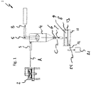
- FIG. 1 shows an arrangement of equipment 1 for the production of powder coatings.
- the equipment 1 comprises a mill or grinder 2 for grinding flakes of a powder coating material.
- Powder coating material leaving the grinder 2 has a wide particle size distribution, including superfines, oversized particles and particles within the desired particle size range.
- the powder coating material is transferred (arrow A) to a cyclone inlet 3 of a cyclone 4, where the flow of particles is separated into a central upward flow of superfines and a peripheral downward main flow.
- the central upward flow of the lighter superfines is caused by air suction.
- the superfines are discharged (arrow B) via an upper cyclone outlet 5, e.g., to a further filter station, e.g., with filter bags.
- the main flow with the heavier particles flows downward via a lower cyclone outlet 6 and a line 7 to a sieve separator 8 (arrow C).
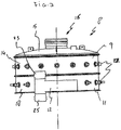
- the sieve separator 8 shown in more detail in Figures 3 - 5 , comprises an upstream chamber 9, a downstream chamber 11 with an outlet 12 and a sieve 13 separating the upstream and downstream chambers 9, 11.
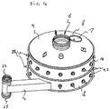
- the upstream chamber 9 comprises a cylindrical peripheral side wall 14 and a lid 15 with a top inlet 16 connected to the lower cyclone outlet 6, and an observation port 17 ( Figure 4 ).
- the downstream chamber 11 is provided with a cylindrical peripheral wall 18.
- the outlet 12 of the downstream chamber 11 extends tangentially from the peripheral side wall 18.
- the top inlet 10, the upstream chamber 9, the sieve 13, and the downstream chamber 11 are coaxially arranged about a central longitudinal axis X of the sieve separator 8 ( Figure 3 ).
- the sieve 13 comprises a supporting frame comprising a cross support 19 ( Figure 5 ).
- Oversized particles are separated by the sieve 13 and remain in the upstream chamber 9.
- the fraction of powder coating particles within the desired particle size range passes the sieve 13 and enters the downstream chamber 11, where they are collected and discharged via the outlet 12 to a filling station 21.
- the powder coating material is packed for further distribution.
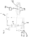
- FIG. 1 shows schematically the cleaning process for the sieve separator 8.
- the upstream chamber 9 and downstream chamber 11 of the sieve separator 8 both comprise a series of nozzles 22 connected to a source of pressurized air or any other type of cleaning gas.
- the nozzles 22 are typically mounted at regular intervals in the peripheral side walls 14, 18 of the upstream and downstream chambers 9, 11 of the sieve separator 8.
- the nozzles 22 are mainly oriented in a direction substantially parallel to the sieve 13, i.e., mainly tangential or radial relative to the central axis X of the sieve separator 8, so they are directed to an opposite part of the peripheral wall 14, 18 of the upstream or downstream chamber 9, 11.
- the nozzle direction of one or more of the nozzles 22 may be tilted relative to the sieve surface.
- the axial and/or tangential flows will cause vortices and a swirling flow of cleaning gas over the surface of the sieve 13.
- the swirls loosen and lift the oversized particles left in the upstream chamber 9 of the sieve separator 8.
- the cleaning gas is discharged together with the particles via the lower cyclone outlet 6 to the upper cyclone outlet 5 and further.
- the cyclone inlet 3 is closed.
- the sieve outlet 12 has an upwardly directed branch 23 connected to a cleaning gas discharge line 24 ( Figure 2 ) and a downwardly directed branch 25 leading to the filling station 14.
- the sieve outlet 12 is provided with a valve 16 ( Figure 1 ) which can selectively be put in a first position, guiding the flow via the downwardly directed branch to the filling station 21, and a second position to guide the flow via the cleaning gas discharge line 24 joining the discharge line of the cyclone 4.
- the cleaning gas nozzles 22 are connected to a manifold 26 for distributing cleaning gas from a source of pressurized cleaning gas.
- the manifold 26 has a number of outlets 28, each comprising a valve under the control of a control unit 29. Each outlet 28 is connected to a single nozzle 22 of the sieve separator 8.
- the control unit 29 opens a valve of an outlet 28, pressurized cleaning gas is jetted through the associated nozzle 22 into the upstream or downstream chamber 9, 11 of the sieve separator 8.
- the control unit 29 is programmed to release the cleaning gas pulse wise.
- the control unit 29 can open a number of valves simultaneously or consecutively to create a desired pattern of flows and vortices over the sieve surface.
- the control unit 29 can be programmed to activate the valves of the outlets 28 in a certain sequence and can be programmed to control the duration of the pulses, the duration of the time interval between the pulses and/or the flow velocity of the pulses.
- the control unit 29 can also control the orientation of the nozzles 22 and the direction of the pulses.
- the program to be carried out by the control unit 29 may for example depend on the colour difference between two consecutive powder coating batches.
- a more intensive program may be followed (e.g., a longer program or with longer or stronger pulses) than if the batches are only slightly different grades of the same colour.
- a more intensive program may be applied.
- the cleaning gas will typically be pressurized air.
Landscapes
- Cyclones (AREA)
- Combined Means For Separation Of Solids (AREA)
Abstract
- an upstream chamber (9) with an inlet (16);
- a downstream chamber (11) comprising an outlet (12);
- a sieve (13) separating the upstream and downstream chambers;
- nozzles (22) connected to a supply for pressurized cleaning gas, oriented to create a swirling gas flow along a surface of the sieve.
Description
- The present disclosure relates to a sieve separator, in particular for sieving ground powder coatings. The invention also relates to grinding equipment including such a sieve separator and to a process of cleaning such a sieve separator.
- In the manufacturing of powder coatings, granules of a polymer binder material are mixed with hardener, pigments and other powder ingredients and subsequently heated and extruded. The extruded mixture is rolled flat, cooled and broken into flakes, which are subsequently ground and milled in a grinder to form a powder. The resulting powder has a broad range of particle sizes. In a first step the particles that are too small (the so-called "superfines") are separated, typically by cyclonic separation. In a next step, the oversized particles are separated, typically by a sieve separator. The oversized particles can be returned to the grinder or processed as waste.
- Subsequent batches of powder coatings may differ in colour, composition and/or particle size distribution. After the production of a batch, the process equipment needs to be thoroughly cleaned before the production of a next batch of a different colour or chemistry can start.
- In particular the sieve separator may contain residues of a prior batch which can cause significant deviations of the desired colour in the final powder product. To clean the sieve separator, the device must be dismantled manually. This is laborious and ergonomically difficult work, which significantly increases standstill time of the processing equipment. Cleaning of the sieve separator typically takes from 15-30 minutes.
-
CN202984093U discloses a system for cleaning screens used in a flour factory, using a pulse control valve to flush the screen with air. The air is jetted upwardly through the screen. The jets mainly clean the screen where they cross the screen and do not provide the degree of overall cleaning as required in a powder coating production environment. - Flushing screens by a back flow of a cleaning gas is for instance disclosed in
JP2006075722 - The object of the invention is achieved with a sieve separator comprising:
- an upstream chamber with an inlet;
- a downstream chamber comprising an outlet;
- a sieve separating the upstream and downstream chambers;
- nozzles connected to a supply for pressurized cleaning gas, oriented to create a swirling gas flow along a surface of the sieve.
- In this system the separator does not need to be opened and dismantled for cleaning. The sieve separator can be cleaned in a fast and efficient manner. The standstill time can be reduced to 8 minutes or even less. This way of cleaning is also a substantial improvement for the health and safety of the operator.
- In a specific embodiment, the sieve separator comprises nozzles at the upstream and downstream sides of the sieve, e.g., along the circumference of the sieve, e.g., in a peripheral wall encasing the sieve. This facilitates efficient cleaning of both sides of the sieve in the upstream chamber as well as in the downstream chamber.
- The sieve separator may comprise a control unit configured to control the nozzles to supply the cleaning gas pulse-wise. The control unit can be configured to control the nozzles independently and sequentially, e.g., according to programmed patterns. The control unit can for example control direction, duration and/or flow velocity of the pulses, and/or sequence of activation of the nozzles. Different programs can be selected for different situations. For example, if two consecutive batches have strongly contrasting colours, an intensive program can be run with stronger and/or longer pulses than would be used between two batches of slightly differing colours. A suitable program may for example be selectable by an operator via a suitable user interface.
- The duration of the individual pulses may for example be at least one second, e.g., up to about 10 seconds. The flow of the jets can be regulated, if needed.
- To obtain an effective swirl, the nozzles can be mainly oriented in a direction substantially parallel to the sieve, i.e., mainly tangential or radial relative to a central axis of the sieve. Optionally, the nozzles can be slightly tilted in the axial direction, as long as they are directed towards an opposite part of the peripheral wall of the upstream or downstream chamber. The nozzles can have the same orientation or they can have different orientations, relative to the central axis through the sieve.
- The nozzles can be evenly spaced and can be of the same type and size. In alternative embodiments, different types of nozzles and/or different arrangements can be used, e.g., to create specific patterns of vortices.
- The sieve separator is typically used in combination with a grinder for milling the powder coatings. The milled powder coatings material is transported via a line from the grinder to the inlet of the upstream chamber of the sieve separator. This line typically comprises a cyclone separator for separation of the superfines. In the cyclone separator a vortex is created in the passing gas flow, centrifugally separating the light superfines from the heavier powder coating particles. The superfines are discharged via an exhaust to a further filter station, e.g., with filter bags, while the larger particles leave the cyclone via an outlet to the upstream chamber of the sieve separator. During cleaning, the pulsed cleaning gas can for example be discharged from the upstream chamber in the reverse direction. This way, the spent cleaning gas flows into the cyclone carrying the oversized particles separated by the sieve. Accordingly, the cyclone defines a discharge flow path for used cleaning gas leaving the upstream chamber of the sieve separator. Eventually the cleaning gas is discharged via the same exhaust as used for discharging the superfines.
- The downstream chamber of the sieve separator may comprise an outlet with a valve, selectively moveable between a default position, allowing discharge of sieved powder coatings to a filling station, and a cleaning position, allowing discharge of used cleaning gas. The used cleaning gas can from example be discharged to the same downstream filter stations as the superfines leaving the cyclone separator.
- The above-described aspects will hereafter be more explained with further details and benefits with reference to the drawings showing an exemplary embodiment.
- Figure 1:
- schematically shows equipment for processing grinded powder coatings;
- Figure 2:
- schematically shows the equipment of
Figure 1 during a cleaning process of the present disclosure; - Figure 3:
- shows a front view of the sieve separator of the equipment shown in
Figure 1 ; - Figure 4:
- shows the sieve separator of
Figure 3 in perspective top view; - Figure 5:
- shows the sieve separator of
Figure 3 in perspective bottom view. -
Figure 1 shows an arrangement ofequipment 1 for the production of powder coatings. Theequipment 1 comprises a mill orgrinder 2 for grinding flakes of a powder coating material. Powder coating material leaving thegrinder 2 has a wide particle size distribution, including superfines, oversized particles and particles within the desired particle size range. The powder coating material is transferred (arrow A) to a cyclone inlet 3 of acyclone 4, where the flow of particles is separated into a central upward flow of superfines and a peripheral downward main flow. The central upward flow of the lighter superfines is caused by air suction. The superfines are discharged (arrow B) via anupper cyclone outlet 5, e.g., to a further filter station, e.g., with filter bags. The main flow with the heavier particles flows downward via a lower cyclone outlet 6 and a line 7 to a sieve separator 8 (arrow C). - The
sieve separator 8, shown in more detail inFigures 3 - 5 , comprises anupstream chamber 9, a downstream chamber 11 with anoutlet 12 and asieve 13 separating the upstream anddownstream chambers 9, 11. Theupstream chamber 9 comprises a cylindricalperipheral side wall 14 and alid 15 with atop inlet 16 connected to the lower cyclone outlet 6, and an observation port 17 (Figure 4 ). Also the downstream chamber 11 is provided with a cylindricalperipheral wall 18. Theoutlet 12 of the downstream chamber 11 extends tangentially from theperipheral side wall 18. The top inlet 10, theupstream chamber 9, thesieve 13, and the downstream chamber 11 are coaxially arranged about a central longitudinal axis X of the sieve separator 8 (Figure 3 ). - The
sieve 13 comprises a supporting frame comprising a cross support 19 (Figure 5 ). - Oversized particles are separated by the
sieve 13 and remain in theupstream chamber 9. The fraction of powder coating particles within the desired particle size range passes thesieve 13 and enters the downstream chamber 11, where they are collected and discharged via theoutlet 12 to a fillingstation 21. Here, the powder coating material is packed for further distribution. - Before production of a following batch of a different colour, the
equipment 1 must be cleaned, in particular thesieve separator 8, in order to avoid contamination.Figure 2 shows schematically the cleaning process for thesieve separator 8. - The
upstream chamber 9 and downstream chamber 11 of thesieve separator 8 both comprise a series ofnozzles 22 connected to a source of pressurized air or any other type of cleaning gas. Thenozzles 22 are typically mounted at regular intervals in theperipheral side walls downstream chambers 9, 11 of thesieve separator 8. Thenozzles 22 are mainly oriented in a direction substantially parallel to thesieve 13, i.e., mainly tangential or radial relative to the central axis X of thesieve separator 8, so they are directed to an opposite part of theperipheral wall downstream chamber 9, 11. Optionally, the nozzle direction of one or more of thenozzles 22 may be tilted relative to the sieve surface. Within the confinement of the upstream ordownstream chambers 9, 11 the axial and/or tangential flows will cause vortices and a swirling flow of cleaning gas over the surface of thesieve 13. The swirls loosen and lift the oversized particles left in theupstream chamber 9 of thesieve separator 8. By air suction the cleaning gas is discharged together with the particles via the lower cyclone outlet 6 to theupper cyclone outlet 5 and further. During this process the cyclone inlet 3 is closed. - Air in the downstream chamber 11 escapes via the
sieve outlet 12. Thesieve outlet 12 has an upwardly directedbranch 23 connected to a cleaning gas discharge line 24 (Figure 2 ) and a downwardly directedbranch 25 leading to the fillingstation 14. Thesieve outlet 12 is provided with a valve 16 (Figure 1 ) which can selectively be put in a first position, guiding the flow via the downwardly directed branch to the fillingstation 21, and a second position to guide the flow via the cleaninggas discharge line 24 joining the discharge line of thecyclone 4. - The cleaning
gas nozzles 22 are connected to a manifold 26 for distributing cleaning gas from a source of pressurized cleaning gas. The manifold 26 has a number ofoutlets 28, each comprising a valve under the control of acontrol unit 29. Eachoutlet 28 is connected to asingle nozzle 22 of thesieve separator 8. When thecontrol unit 29 opens a valve of anoutlet 28, pressurized cleaning gas is jetted through the associatednozzle 22 into the upstream ordownstream chamber 9, 11 of thesieve separator 8. - The
control unit 29 is programmed to release the cleaning gas pulse wise. Thecontrol unit 29 can open a number of valves simultaneously or consecutively to create a desired pattern of flows and vortices over the sieve surface. Thecontrol unit 29 can be programmed to activate the valves of theoutlets 28 in a certain sequence and can be programmed to control the duration of the pulses, the duration of the time interval between the pulses and/or the flow velocity of the pulses. Optionally, thecontrol unit 29 can also control the orientation of thenozzles 22 and the direction of the pulses. The program to be carried out by thecontrol unit 29 may for example depend on the colour difference between two consecutive powder coating batches. If there is a strong colour contrast between the previous batch and the following batch, a more intensive program may be followed (e.g., a longer program or with longer or stronger pulses) than if the batches are only slightly different grades of the same colour. Similarly, if the preceding batch contains sticky constituents, e.g., a tacky binder component, a more intensive program may be applied. - The cleaning gas will typically be pressurized air.
- It is noted that the drawings are schematic, not necessarily to scale and that details that are not required for understanding the present invention may have been omitted. The terms "upstream" and "downstream" refer to the flow direction during production, not to the flow direction of the cleaning gas during cleaning. The terms "below", "above", and the like relate to the embodiments as oriented in the drawings, unless otherwise specified.
- The disclosure is not restricted to the above described embodiments which can be varied in a number of ways within the scope of the claims.
Claims (14)
- A sieve separator (8) comprising:- an upstream chamber (9) with an inlet (16);- a downstream chamber (11) comprising an outlet (12);- a sieve (13) separating the upstream and downstream chambers;- nozzles (22) connected to a supply for pressurized cleaning gas, oriented to create a swirling gas flow along a surface of the sieve.
- The sieve separator of claim 1, comprising nozzles (22) at the upstream side and at the downstream side of the sieve (13).
- The sieve separator of claim 1 or 2, wherein the nozzles (22) are arranged along the circumference of the sieve (13).
- The sieve separator of claim 1, 2 or 3, comprising a control unit (29) configured to control the nozzles (22) to supply the cleaning gas pulse-wise.
- The sieve separator of claim 4, wherein the control unit (29) is configured to control the nozzles (22) independently and sequentially, e.g., according to programmed patterns.
- The sieve separator according to claim 5, wherein the control unit (29) controls direction, duration and/or flow velocity of the pulses, and/or sequence of activation of the nozzles (22).
- The sieve separator of any preceding claim, wherein the nozzles (22) are mainly oriented in a direction substantially parallel to the sieve (13).
- The sieve separator of any one of the preceding claims, wherein the outlet (12) of the downstream chamber (11) comprises a valve (30), selectively moveable between a default position, allowing discharge of sieved powder coatings to a filling station (21), and a cleaning position, allowing discharge of used cleaning gas.
- Equipment for grinding powder coatings comprising a grinder (2) and a sieve separator (8) according to any preceding claim, and a line for transporting powder from the grinder to the inlet (16) of the upstream chamber of the sieve separator.
- Equipment according to claim 9, wherein the line between the grinder (2) and the sieve separator (8) comprises a cyclone separator (4).
- Equipment according to claim 10, wherein the cyclone (4) defines a discharge flow path for used cleaning gas leaving the upstream chamber (9) of the sieve separator.
- Process of cleaning a sieve (13) of a sieve separator (8) of a powder coating grinder by generating a swirling flow of a cleaning gas over a surface of the sieve.
- Process according to claim 12, wherein the cleaning gas is jetted pulse wise.
- Process according to claim 12 or 13, wherein the cleaning gas is blown into the upstream and/or downstream chamber (9, 11) of the sieve separator consecutively via different nozzles (22).
Priority Applications (5)
| Application Number | Priority Date | Filing Date | Title |
|---|---|---|---|
| EP19192258.2A EP3782740A1 (en) | 2019-08-19 | 2019-08-19 | Sieve separator, grinding equipment for powder coatings and process of cleaning a sieve separator |
| CN202080058544.7A CN114269485A (en) | 2019-08-19 | 2020-08-17 | Screen separator, powder coating grinding apparatus, and screen separator cleaning method |
| EP20754274.7A EP4017652A1 (en) | 2019-08-19 | 2020-08-17 | Sieve separator, grinding equipment for powder coatings and process of cleaning a sieve separator |
| PCT/EP2020/072961 WO2021032662A1 (en) | 2019-08-19 | 2020-08-17 | Sieve separator, grinding equipment for powder coatings and process of cleaning a sieve separator |
| US17/636,468 US20220280976A1 (en) | 2019-08-19 | 2020-08-17 | Sieve Separator, Grinding Equipment for Powder Coatings and Process of Cleaning a Sieve Separator |
Applications Claiming Priority (1)
| Application Number | Priority Date | Filing Date | Title |
|---|---|---|---|
| EP19192258.2A EP3782740A1 (en) | 2019-08-19 | 2019-08-19 | Sieve separator, grinding equipment for powder coatings and process of cleaning a sieve separator |
Publications (1)
| Publication Number | Publication Date |
|---|---|
| EP3782740A1 true EP3782740A1 (en) | 2021-02-24 |
Family
ID=67659250
Family Applications (2)
| Application Number | Title | Priority Date | Filing Date |
|---|---|---|---|
| EP19192258.2A Withdrawn EP3782740A1 (en) | 2019-08-19 | 2019-08-19 | Sieve separator, grinding equipment for powder coatings and process of cleaning a sieve separator |
| EP20754274.7A Withdrawn EP4017652A1 (en) | 2019-08-19 | 2020-08-17 | Sieve separator, grinding equipment for powder coatings and process of cleaning a sieve separator |
Family Applications After (1)
| Application Number | Title | Priority Date | Filing Date |
|---|---|---|---|
| EP20754274.7A Withdrawn EP4017652A1 (en) | 2019-08-19 | 2020-08-17 | Sieve separator, grinding equipment for powder coatings and process of cleaning a sieve separator |
Country Status (4)
| Country | Link |
|---|---|
| US (1) | US20220280976A1 (en) |
| EP (2) | EP3782740A1 (en) |
| CN (1) | CN114269485A (en) |
| WO (1) | WO2021032662A1 (en) |
Citations (5)
| Publication number | Priority date | Publication date | Assignee | Title |
|---|---|---|---|---|
| DE845741C (en) * | 1948-10-02 | 1952-08-04 | Christian Dr-Ing Schmid | Process for cleaning plan sifter sieves and equipment for carrying out the process |
| DE19532770A1 (en) * | 1995-09-05 | 1997-03-06 | Herbert Horlamus | Continuously operating air sieve |
| JP2006075722A (en) | 2004-09-09 | 2006-03-23 | Asahi Sunac Corp | Powder coating equipment |
| CN202984093U (en) | 2012-12-25 | 2013-06-12 | 晨光生物科技集团股份有限公司 | Automatic cleaning device for screen surfaces of screening equipment |
| US20130327685A1 (en) * | 2012-06-07 | 2013-12-12 | Ricoh Company, Ltd. | Oscillating sieve |
Family Cites Families (7)
| Publication number | Priority date | Publication date | Assignee | Title |
|---|---|---|---|---|
| US4251355A (en) * | 1979-09-06 | 1981-02-17 | Monsanto Company | Apparatus for separating snakeskins and fines from polymeric pellets |
| CN1224370A (en) * | 1996-07-04 | 1999-07-28 | 赛孚罗德公司 | Cleaning equipment for gases, especially flame fumes |
| FR2825361B1 (en) * | 2001-06-01 | 2003-08-01 | Efit Environnemnt Filtration E | PROCESS AND INSTALLATION FOR REMOVING METAL PARTICLES FROM A CONCRETE |
| US8485364B2 (en) * | 2010-01-05 | 2013-07-16 | Kroosh Technologies | Multifrequency sieve assembly for circular vibratory separator |
| CN207103120U (en) * | 2017-07-13 | 2018-03-16 | 湖北黄仙洞葛业食品有限公司 | A kind of knot screen for kudzu-vine root powder |
| CN107159561A (en) * | 2017-07-13 | 2017-09-15 | 湖北黄仙洞葛业食品有限公司 | A kind of knot screen for kudzu-vine root powder |
| CN108620319A (en) * | 2018-06-12 | 2018-10-09 | 王荣 | A kind of novel cleaning unit |
-
2019
- 2019-08-19 EP EP19192258.2A patent/EP3782740A1/en not_active Withdrawn
-
2020
- 2020-08-17 WO PCT/EP2020/072961 patent/WO2021032662A1/en not_active Ceased
- 2020-08-17 EP EP20754274.7A patent/EP4017652A1/en not_active Withdrawn
- 2020-08-17 CN CN202080058544.7A patent/CN114269485A/en active Pending
- 2020-08-17 US US17/636,468 patent/US20220280976A1/en not_active Abandoned
Patent Citations (5)
| Publication number | Priority date | Publication date | Assignee | Title |
|---|---|---|---|---|
| DE845741C (en) * | 1948-10-02 | 1952-08-04 | Christian Dr-Ing Schmid | Process for cleaning plan sifter sieves and equipment for carrying out the process |
| DE19532770A1 (en) * | 1995-09-05 | 1997-03-06 | Herbert Horlamus | Continuously operating air sieve |
| JP2006075722A (en) | 2004-09-09 | 2006-03-23 | Asahi Sunac Corp | Powder coating equipment |
| US20130327685A1 (en) * | 2012-06-07 | 2013-12-12 | Ricoh Company, Ltd. | Oscillating sieve |
| CN202984093U (en) | 2012-12-25 | 2013-06-12 | 晨光生物科技集团股份有限公司 | Automatic cleaning device for screen surfaces of screening equipment |
Also Published As
| Publication number | Publication date |
|---|---|
| WO2021032662A1 (en) | 2021-02-25 |
| US20220280976A1 (en) | 2022-09-08 |
| CN114269485A (en) | 2022-04-01 |
| EP4017652A1 (en) | 2022-06-29 |
Similar Documents
| Publication | Publication Date | Title |
|---|---|---|
| CA2940058C (en) | System and method for fractionating grain | |
| CN109641217B (en) | Method for operating a multi-body cyclone separation mechanism to separate fine and ultrafine particles and a multi-body cyclone separation mechanism | |
| DE69300702T2 (en) | Powder coating. | |
| EP2214842B1 (en) | Wash down dedusting apparatus | |
| NL2025437B1 (en) | Apparatus and method for screening powders | |
| EP3347288B1 (en) | Mixing silo design for dust removal and methods of using the same | |
| DE2856536A1 (en) | IMPACT SEPARATOR FOR THE REMOVAL OF COATING MATERIALS FROM THE SURFACE OF GRAINY GOODS | |
| DE2546920C3 (en) | Electrostatic powder coating system | |
| DE102007046622A1 (en) | Device for conveying and mixing bulk material | |
| EP2239051B1 (en) | Processing device for bulk material | |
| CA2991105A1 (en) | Continuous particle manufacturing device | |
| JPS6324426B2 (en) | ||
| US20220280976A1 (en) | Sieve Separator, Grinding Equipment for Powder Coatings and Process of Cleaning a Sieve Separator | |
| US7478771B2 (en) | Methods for recrushing rocks and removing fines therefrom | |
| US4137155A (en) | Method of and apparatus for pneumatically sorting heterogeneous mixtures | |
| US20100163463A1 (en) | Apparatus and method for separating contaminating particles from an incoherent mass of woody material and/or vegetable fibers | |
| RU2104099C1 (en) | Pneumatic separation device for grain cleaner | |
| JP6526502B2 (en) | Continuous particle production system | |
| US1792962A (en) | Pneumatic separator | |
| EP3124110A1 (en) | A process and spray drying apparatus for spray drying products | |
| DE19718668C2 (en) | Process for separating and continuously removing difficult-to-disperse components | |
| RU2057588C1 (en) | Method and eddy mill for vortex grinding | |
| WO2004048006A1 (en) | Method and device for separating dust particles from a granulate | |
| RU2141878C1 (en) | Method of sorting ground materials and device for realization of this method | |
| AU2021448036B2 (en) | A system and a method for micronization of solid particles using valvular conduit |
Legal Events
| Date | Code | Title | Description |
|---|---|---|---|
| PUAI | Public reference made under article 153(3) epc to a published international application that has entered the european phase |
Free format text: ORIGINAL CODE: 0009012 |
|
| STAA | Information on the status of an ep patent application or granted ep patent |
Free format text: STATUS: THE APPLICATION HAS BEEN PUBLISHED |
|
| AK | Designated contracting states |
Kind code of ref document: A1 Designated state(s): AL AT BE BG CH CY CZ DE DK EE ES FI FR GB GR HR HU IE IS IT LI LT LU LV MC MK MT NL NO PL PT RO RS SE SI SK SM TR |
|
| AX | Request for extension of the european patent |
Extension state: BA ME |
|
| STAA | Information on the status of an ep patent application or granted ep patent |
Free format text: STATUS: THE APPLICATION HAS BEEN WITHDRAWN |
|
| 18W | Application withdrawn |
Effective date: 20210722 |
|
| RAP3 | Party data changed (applicant data changed or rights of an application transferred) |
Owner name: AKZO NOBEL COATINGS INTERNATIONAL B.V. |