EP3782723A1 - System and method for performing separation and dehydroxylation of fumed silica soot particles - Google Patents
System and method for performing separation and dehydroxylation of fumed silica soot particles Download PDFInfo
- Publication number
- EP3782723A1 EP3782723A1 EP20191015.5A EP20191015A EP3782723A1 EP 3782723 A1 EP3782723 A1 EP 3782723A1 EP 20191015 A EP20191015 A EP 20191015A EP 3782723 A1 EP3782723 A1 EP 3782723A1
- Authority
- EP
- European Patent Office
- Prior art keywords
- silica particles
- fumed silica
- dehydroxylation
- double entry
- fluidized
- Prior art date
- Legal status (The legal status is an assumption and is not a legal conclusion. Google has not performed a legal analysis and makes no representation as to the accuracy of the status listed.)
- Pending
Links
Images


Classifications
-
- C—CHEMISTRY; METALLURGY
- C03—GLASS; MINERAL OR SLAG WOOL
- C03B—MANUFACTURE, SHAPING, OR SUPPLEMENTARY PROCESSES
- C03B37/00—Manufacture or treatment of flakes, fibres, or filaments from softened glass, minerals, or slags
- C03B37/01—Manufacture of glass fibres or filaments
- C03B37/012—Manufacture of preforms for drawing fibres or filaments
- C03B37/0128—Manufacture of preforms for drawing fibres or filaments starting from pulverulent glass
- C03B37/01282—Manufacture of preforms for drawing fibres or filaments starting from pulverulent glass by pressing or sintering, e.g. hot-pressing
-
- C—CHEMISTRY; METALLURGY
- C01—INORGANIC CHEMISTRY
- C01B—NON-METALLIC ELEMENTS; COMPOUNDS THEREOF; METALLOIDS OR COMPOUNDS THEREOF NOT COVERED BY SUBCLASS C01C
- C01B33/00—Silicon; Compounds thereof
- C01B33/113—Silicon oxides; Hydrates thereof
- C01B33/12—Silica; Hydrates thereof, e.g. lepidoic silicic acid
- C01B33/18—Preparation of finely divided silica neither in sol nor in gel form; After-treatment thereof
-
- C—CHEMISTRY; METALLURGY
- C01—INORGANIC CHEMISTRY
- C01B—NON-METALLIC ELEMENTS; COMPOUNDS THEREOF; METALLOIDS OR COMPOUNDS THEREOF NOT COVERED BY SUBCLASS C01C
- C01B33/00—Silicon; Compounds thereof
- C01B33/113—Silicon oxides; Hydrates thereof
- C01B33/12—Silica; Hydrates thereof, e.g. lepidoic silicic acid
- C01B33/18—Preparation of finely divided silica neither in sol nor in gel form; After-treatment thereof
- C01B33/181—Preparation of finely divided silica neither in sol nor in gel form; After-treatment thereof by a dry process
-
- B—PERFORMING OPERATIONS; TRANSPORTING
- B01—PHYSICAL OR CHEMICAL PROCESSES OR APPARATUS IN GENERAL
- B01D—SEPARATION
- B01D45/00—Separating dispersed particles from gases or vapours by gravity, inertia, or centrifugal forces
- B01D45/12—Separating dispersed particles from gases or vapours by gravity, inertia, or centrifugal forces by centrifugal forces
- B01D45/16—Separating dispersed particles from gases or vapours by gravity, inertia, or centrifugal forces by centrifugal forces generated by the winding course of the gas stream, the centrifugal forces being generated solely or partly by mechanical means, e.g. fixed swirl vanes
-
- B—PERFORMING OPERATIONS; TRANSPORTING
- B01—PHYSICAL OR CHEMICAL PROCESSES OR APPARATUS IN GENERAL
- B01J—CHEMICAL OR PHYSICAL PROCESSES, e.g. CATALYSIS OR COLLOID CHEMISTRY; THEIR RELEVANT APPARATUS
- B01J8/00—Chemical or physical processes in general, conducted in the presence of fluids and solid particles; Apparatus for such processes
- B01J8/005—Separating solid material from the gas/liquid stream
- B01J8/0055—Separating solid material from the gas/liquid stream using cyclones
-
- B—PERFORMING OPERATIONS; TRANSPORTING
- B01—PHYSICAL OR CHEMICAL PROCESSES OR APPARATUS IN GENERAL
- B01J—CHEMICAL OR PHYSICAL PROCESSES, e.g. CATALYSIS OR COLLOID CHEMISTRY; THEIR RELEVANT APPARATUS
- B01J8/00—Chemical or physical processes in general, conducted in the presence of fluids and solid particles; Apparatus for such processes
- B01J8/18—Chemical or physical processes in general, conducted in the presence of fluids and solid particles; Apparatus for such processes with fluidised particles
- B01J8/1818—Feeding of the fluidising gas
- B01J8/1827—Feeding of the fluidising gas the fluidising gas being a reactant
-
- B—PERFORMING OPERATIONS; TRANSPORTING
- B04—CENTRIFUGAL APPARATUS OR MACHINES FOR CARRYING-OUT PHYSICAL OR CHEMICAL PROCESSES
- B04C—APPARATUS USING FREE VORTEX FLOW, e.g. CYCLONES
- B04C5/00—Apparatus in which the axial direction of the vortex is reversed
- B04C5/02—Construction of inlets by which the vortex flow is generated, e.g. tangential admission, the fluid flow being forced to follow a downward path by spirally wound bulkheads, or with slightly downwardly-directed tangential admission
-
- B—PERFORMING OPERATIONS; TRANSPORTING
- B04—CENTRIFUGAL APPARATUS OR MACHINES FOR CARRYING-OUT PHYSICAL OR CHEMICAL PROCESSES
- B04C—APPARATUS USING FREE VORTEX FLOW, e.g. CYCLONES
- B04C5/00—Apparatus in which the axial direction of the vortex is reversed
- B04C5/20—Apparatus in which the axial direction of the vortex is reversed with heating or cooling, e.g. quenching, means
-
- C—CHEMISTRY; METALLURGY
- C03—GLASS; MINERAL OR SLAG WOOL
- C03B—MANUFACTURE, SHAPING, OR SUPPLEMENTARY PROCESSES
- C03B19/00—Other methods of shaping glass
- C03B19/06—Other methods of shaping glass by sintering, e.g. by cold isostatic pressing of powders and subsequent sintering, by hot pressing of powders, by sintering slurries or dispersions not undergoing a liquid phase reaction
-
- B—PERFORMING OPERATIONS; TRANSPORTING
- B01—PHYSICAL OR CHEMICAL PROCESSES OR APPARATUS IN GENERAL
- B01J—CHEMICAL OR PHYSICAL PROCESSES, e.g. CATALYSIS OR COLLOID CHEMISTRY; THEIR RELEVANT APPARATUS
- B01J2208/00—Processes carried out in the presence of solid particles; Reactors therefor
- B01J2208/00743—Feeding or discharging of solids
- B01J2208/00769—Details of feeding or discharging
Definitions
- the present invention relates to the field of manufacturing of optical fibers and, in particular, relates to a system and method for performing separation and dehydroxylation of fumed silica particles.
- optical fibers have two major stages. The first stage involves the manufacturing of optical fiber preforms and the second stage involves drawing the optical fibers from the optical fiber preforms.
- the quality of optical fibers depends on conditions of manufacturing. So, a lot of attention is paid towards the manufacturing of the optical fiber preforms with good characteristics.
- These optical fiber preforms include an inner glass core surrounded by a glass cladding having a lower index of refraction than the inner glass core. The dehydration of silica is a requisite in optical fiber manufacturing to remove OH from optical fiber preform.
- the silica particles obtained after processes such as OVD is geometry and density specific. This poses a challenge for performing dehydration of the silica particles in the perform requires continuous processing by coming in contact with reagent and getting treated with heat. The improper processing of the f silica particles may affect the quality of the optical fiber preform.
- the present disclosure provides a separator system for performing separation and dehydroxylation of fumed silica particles.
- the separator system includes a first inlet.
- the separator system includes a second inlet.
- the separator system includes a main body of a double entry cyclone.
- the separator system includes a first outlet.
- the separator system includes a second outlet.
- the first inlet is utilized for collecting a primary feed of fumed silica particles from a gaseous stream into a double entry cyclone.
- the primary feed of fumed silica particles is collected in a fluidized (free flowing) state.
- the second inlet is utilized for collecting a secondary feed of chlorine gas into the double entry cyclone.
- the secondary feed of chlorine gas is collected for performing dehydroxylation of the fluidized (free flowing) fumed silica particles.
- the main body of the double entry cyclone is utilized in treating the primary feed of the silica particles and the secondary feed of chlorine gas along with heat inside the double entry cyclone.
- the first outlet is utilized for releasing the dehydrated silica particles.
- the second outlet is utilized for releasing the water molecules and other gases after performing dehydroxylation of the fumed silica particles.
- a primary object of the present disclosure is to provide a system to perform separation of fumed silica particles from a gaseous stream.
- Another object of the present disclosure is to provide the system to perform dehydroxylation of the fumed silica particles.
- Yet another object of the present disclosure is to provide the system to perform separation and dehydroxylation of the fumed silica particles in a double entry cyclone separator.
- Yet another object of the present disclosure is to reduce overall time while performing separation and dehydroxylation of the fumed silica particles.
- Yet another object of the present disclosure is to increase production and minimize wastage after performing separation and dehydroxylation of the fumed silica particles.
- Yet another object of the present disclosure is to perform dehydroxylation of the fluidized (free flowing) fumed silica particles in a chamber.
- Yet another object of the present disclosure is to perform dehydroxylation of the fluidized (free flowing) fumed silica particles in one or more chambers.
- Yet another object of the present disclosure is to perform dehydroxylation of low porosity with the defined geometry fumed silica particles.
- the present disclosure provides a separator system for performing separation and dehydroxylation of fumed silica particles.
- the separator system includes a first inlet.
- the separator system includes a second inlet.
- the separator system includes a main body of a double entry cyclone.
- the separator system includes a first outlet.
- the separator system includes a second outlet.
- the first inlet is utilized for collecting a primary feed of fumed silica particles from a gaseous stream into a double entry cyclone.
- the primary feed of fumed silica particles is collected in a fluidized (free flowing) state.
- the second inlet is utilized for collecting a secondary feed of chlorine gas into the double entry cyclone.
- the secondary feed of chlorine gas is collected for performing dehydroxylation of the fluidized (free flowing) fumed silica particles in the cyclone.
- the main body of the double entry cyclone is utilized in treating the primary feed of the silica particles and the secondary feed of chlorine gas along with heat inside the double entry cyclone.
- the heat is provided for chemical reaction by high temperature environment inside the cyclone.
- the first outlet is utilized for releasing the dehydrated silica particles.
- the second outlet is utilized for releasing the water molecules and other gases after performing dehydroxylation of the fumed silica particles.
- the vortex formation imparts centrifugal force on the fluidized (free flowing) fumed silica particles.
- the separation and dehydroxylation of the fumed silica particles happens for releasing dehydrated fumed silica particles and water molecules.
- fumed silica particles undergoes dehydroxylation for removing physiosorbed water molecules and chemisorbed water molecules.
- the chemisorbed water molecules are removed after removal of the physiosorbed water molecules.
- the physiosorbed water molecules are removed at a temperature of about 200° Celsius.
- the chemisorbed water molecules remaining after temperature of 200° Celsius is in range of about 30 parts per million to 50 parts per million.
- the separator system (100) performs dehydroxylation of isolated SiOH groups, geminal SiOH groups and vicinal SiOH groups.
- the fumed silica particles undergoes separation and dehydroxylation in a time period.
- the time period for separation and dehydroxylation of the fumed silica particles depends upon one or more factors.
- the present disclosure provides a method.
- the method performs separation of fumed silica particles.
- the method includes a first step to collect a primary feed of fumed silica particles from a gaseous stream into a double entry cyclone from a first inlet.
- the method includes another step to collect a secondary feed of chlorine gas into the double entry cyclone from a second inlet.
- the method includes another step to treat the primary feed of the fumed silica particles and the secondary feed of chlorine gas along with heat inside a main body of the double entry cyclone.
- the method includes another step to release the dehydrated fumed silica particles from a first outlet.
- the method includes another step to release the water molecules and other gases after performing separation of the fumed silica particles from a second outlet.
- the primary feed of fumed silica particles is collected in a fluidized (free flowing) state.
- the secondary feed of chlorine gas is collected to perform dehydroxylation of the fluidized (free flowing) fumed silica particles.
- the method includes another step to perform dehydroxylation of the fluidized (free flowing) fumed silica particles in a chamber.
- the dehydroxylation is performed after performing separation of the fumed silica particles in the double entry cyclone.
- the chamber is surrounded by one or more induction furnaces.
- the method includes another step to perform dehydroxylation of the fluidized (free flowing) fumed silica particles in one or more chambers.
- the dehydroxylation is performed after performing separation of the fumed silica particles in the double entry cyclone.
- the one or more chambers are surrounded by one or more induction furnaces.
- the method includes another step to perform compaction of the fluidized (free flowing) fumed silica particles using a punch and a die apparatus.
- the compaction is performed after performing separation of the fumed silica particles in the double entry cyclone.
- the compaction is performed for performing dehydroxylation of compacted fumed silica particles.
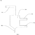
- FIG. 1 illustrates a general overview of a separator system 100 to perform separation and dehydroxylation of fumed silica particles, in accordance with various embodiments of the present disclosure.
- FIG. 2 illustrates a two dimensional view of the separator system 100 to perform separation and dehydroxylation of fumed silica particles, in accordance with various embodiments of the present disclosure.
- the separator system 100 performs separation and separation of the fumed silica particles.
- the separator system 100 includes a first inlet 102, and a second inlet 104.
- the separator system 100 includes a main body 106 of a double entry cyclone, a first outlet 108 and a second outlet 110.
- silica particles are white flaky substance consisting largely of silica, used in manufacturing of optical fiber preforms.
- dehydroxylation is loss or removal of water from something.
- dehydroxylation involves heating process through which hydroxyl group (OH) is released by forming water molecule.
- the separator system 100 includes the first inlet 102.
- the first inlet 102 is utilized to collect a primary feed of fumed silica particles from a gaseous stream into the double entry cyclone.
- the primary feed comes from particle generation system.
- the primary feed contains the fumed silica particles and other gases.
- the first inlet 102 collects the primary feed of silica particles in a fluidized (free flowing) state.
- the first inlet 102 passes the primary feed of the fumed silica particles inside the main body 106 of the double entry cyclone.
- the separator system 100 includes the second inlet 104.
- the second inlet 104 is utilized to collect a secondary feed of chlorine gas into the double entry cyclone.
- the second inlet 104 collects the secondary feed of chlorine gas to perform dehydroxylation of fluidized (free flowing) fumed silica particles.
- the second inlet 104 passes the secondary feed of the fumed silica particles inside the main body 106 of the double entry cyclone.
- the first inlet 102 collects the secondary feed of chlorine gas into the double entry cyclone.
- the second inlet 104 collects the primary feed of the fumed silica particles from the gaseous stream into the double entry cyclone.
- the first inlet 102 and the second inlet 104 may operate interchangeably.
- the primary inlet creates a suction pressure to collect the primary feed of fumed silica particles into the double entry cyclone.
- the secondary inlet creates a suction pressure to collect the secondary feed of chlorine gas into the double entry cyclone.
- the first inlet 102 includes a plurality of nozzles to shower the primary feed of fumed silica particles into the double entry cyclone.
- the second inlet 104 includes the plurality of nozzles to shower the secondary feed of chlorine gas into the double entry cyclone.
- the separator system 100 includes the main body 106 of the double entry cyclone.
- the main body 106 of the double entry cyclone is utilized to treat the primary feed of the silica particles and the secondary feed of chlorine gas along with heat inside the double entry cyclone.
- the double entry cyclone imparts centrifugal force on the fluidized (free flowing) fumed silica particles to perform dehydroxylation and separation of the fumed silica particles.
- the double entry cyclone has higher temperature due to resistance heating.
- resistance heating is defined as heat produced by passing an electric current through a material that preferably has high resistance.
- the double entry cyclone has higher temperature due to induction.
- the double entry cyclone is insulated to prevent leakage of heat from the double entry cyclone.
- the vortex formation is result of design of the double entry cyclone.
- the primary inlet and the secondary inlet collects the primary feed and the secondary feed tangentially such that they result in the vortex formation inside the double entry cyclone.
- primary inlet feed tangentially such that they result in the vortex formation inside the double entry cyclone and secondary inlet feed perpendicular to the primary flow.
- secondary inlet feed tangentially such that they result in the vortex formation inside the double entry cyclone and primary inlet feed perpendicular to the primary flow.
- particulate formed after treatment of the primary feed of the fumed silica particles and the secondary feed of chlorine gas is collected in a hopper.
- the separator system 100 includes the first outlet 108.
- the first outlet 108 is utilized to release SiO 2 particles.
- the first outlet 108 is utilized to release dehydrated fumed silica particles.
- the separator system 100 includes the second outlet 110.
- the second outlet 110 is utilized to release water molecules and other gases after performing separation and dehydroxylation of the fumed silica particles.
- the other gases include HCI, Nitrogen, air and the like.
- the fumed silica particles undergoes dehydroxylation to remove physiosorbed water molecules and chemisorbed water molecules.
- water associated with silica is in one of two forms.
- the two forms includes pysiosorbed water molecules and chemisorbed water molecules.
- the chemisorbed water molecules includes but may not be limited to vicinal silanols, geminal silanols, and isolated silanols.
- the physiosorbed water molecules are removed at temperature of about 200° Celsius.
- the chemisorbed water molecules are removed at temperature greater than 200° Celsius. In an embodiment of the present disclosure, the chemisorbed water molecules remaining after temperature of 200° Celsius is in a range of about 30 parts per million to 50 parts per million.
- the range of the chemisorbed water molecules remaining after temperature of 200° Celsius may vary.
- the chemisorbed water molecules remaining after temperature of 200° Celsius is given by ⁇ OH in a range of 4.6 per nm 2 to 4.9 per nm 2 .
- the physiosorbed water molecules are removed by treating the fumed silica particles up to temperature of about 200° Celsius.
- the chemisorbed water molecules are removed by treating the fumed silica particles above temperature of 200° Celsius.
- the dehydroxylation of the fumed silica particles takes place in presence of the chlorine gas.
- value of n is around 0.91 and the value of Ea is around 44.2 kilojoule per mol at temperature in range of 320° Celsius to 431° Celsius.
- value of n is around 2.00 and the value of Ea is around 88.5 kilojoule per mol at temperature in range of 432° Celsius to 490° Celsius.
- value of n is around 2.00 and the value of Ea is around 101.9 kilojoule per mol at temperature in range of 491° Celsius to 637° Celsius. In yet another embodiment of the present disclosure, value of n is around 2.00 and the value of Ea is around 116.9 kilojoule per mol at temperature in range of 638° Celsius to 758° Celsius. In yet another embodiment of the present disclosure, value of n is around 2.00 and the value of Ea is around 207.6 kilojoule per mol at temperature in range of 759° Celsius to 1122° Celsius.
- the fumed silica particles undergoes separation and dehydroxylation in a time period.
- the time period for separation and dehydroxylation of the fumed silica particles depends upon one or more factors.
- the one or more factors include porosity of the fumed silica particles, geometry of the fumed silica particles, quantity of the fumed silica particles, temperature inside the double entry cyclone, the size of the cyclone, and the like.
- the time period required for dehydroxylation of the fumed silica particles depends on diffusion of chlorine in the silica silica.
- the dehydroxylation of the water molecules from concentration of 30 parts per million at a temperature of 200° Celsius to concentration of 0.1 parts per million for a given geometry and density takes place in time period of about 2 hours when treated at temperature of about 1100° Celsius.
- the time period required for dehydration of the fluidized (free flowing) silica particles of given mass is in a range of about 10 minutes to 15 minutes.
- the time period required for dehydration of the fluidized (free flowing) silica particles depends on particles flowing length inside the cyclone.
- the time taken for thermal diffusion depends on density and geometry of optical fiber preform.
- the dehydrated fumed silica particles from the first outlet 108 of the double entry cyclone are stored in a storage tank.
- the dehydrated fumed silica particles are stored into the storage tank at a flow rate of about 500 grams per minute. In an embodiment of the present disclosure, the dehydrated fumed silica particles are stored into the storage tank at any suitable flow rate.
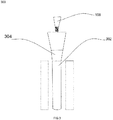
- FIG. 3 illustrates a general overview 300 of a chamber 302 to perform dehydroxylation of fluidized (free flowing) fumed silica particles, in accordance with various embodiments of the present disclosure.
- the chamber 302 is placed below the storage tank 304 placed below the first outlet 108 of the double entry cyclone.
- the chamber 302 is utilized to perform dehyroxylation of the fluidized (free flowing) fumed silica particles.
- the dehydroxylation is performed after performing separation of the fumed silica particles in the double entry cyclone.
- the chamber 302 is surrounded by one or more induction furnaces. The one or more induction furnaces provide heat to the chamber 302.
- the chamber 302 has height of 7 meter. In another embodiment of the present disclosure, height of the chamber 302 may vary. In an embodiment of the present disclosure, the chamber 302 has radius of 10.2 centimeter. In another embodiment of the present disclosure, radius of the chamber 302 may vary. In an embodiment of the present disclosure, the chamber 302 is made of quartz. In another embodiment of the present disclosure, the chamber 302 is made of any other suitable material of the like. In an example, the chamber 302 is capable to treat the fumed silica particles up to weight of 25 kilogram continuously for one hour. In an another example the chamber 302 may be suitably modified to treat the fumed silica particles up to any defined weight for a predetermined time.
- FIG. 4 illustrates a general overview 400 of one or more chambers 302 to perform dehydroxylation of free flowing fumed silica particles, in accordance with various embodiments of the present disclosure.
- the one or more chambers 302 are placed below the storage tank 304 placed below the first outlet 108 of the double entry cyclone.
- the dehydroxylation is performed after performing separation of the fumed silica particles in the double entry cyclone.
- the one or more chambers 302 are surrounded by one or more induction furnaces.
- each chamber of the one or more chambers 302 is surrounded by the one or more induction furnaces.
- the one or more induction furnaces provide heat to the one or more chambers 302.
- each chamber of the one or more chambers 302 has a height of 2 meter. In another embodiment of the present disclosure, height of each chamber of the one or more chambers 302 may vary. In an embodiment of the present disclosure, each chamber of the one or more chambers 302 has radius of 8.5 centimeter. In another embodiment of the present disclosure, radius of each chamber of the one or more chambers 302 may vary. In an embodiment of the present disclosure, each chamber of the one or more chambers 302 is made of quartz. In another embodiment of the present disclosure, each chamber of the one or more chambers 302 is made of any other suitable material of the like. In an example, the one or more chambers 302 are capable to treat the fumed silica particles up to weight of 5 kilogram continuously for one hour. In an another example the one or more chambers 302 may be suitably modified to treat the fumed silica particles up to any defined weight for a predetermined time.
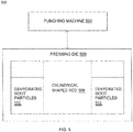
- FIG. 5 illustrates a general overview of a mold assembly 500 to perform compaction of fluidized fumed silica particles 502, in accordance with various embodiments of the present disclosure.
- the fluidized fumed silica particles 502 are separated silica particles released from the first outlet 108 of FIG. 1 .
- the mold assembly 500 includes a punching machine 504, a pressing die 506 and a cylindrical shaped rod 508.
- the punching machine and the pressing die represent a punch and a die apparatus.
- the punch and the die apparatus is used to perform compaction of the fluidized fumed silica particles 502.
- the fluidized fumed silica particles 502 are low porosity with the defined geometry fumed silica particles.
- the dehydroxylation of the low porosity with the defined geometry fumed silica particles is achieved after compaction.
- the compaction is performed after performing separation of the fumed silica particles in the double entry cyclone (as shown in FIG. 1 and FIG. 2 ).
- the compaction is performed for performing dehydroxylation of compacted fumed silica particles.
- the fluidized fumed silica particles 502 are compacted using the mold assembly 500 to manufacture compact silica particles. object.
- the compacted object is sintered to manufacture a clad preform.
- the mold assembly 500 performs pressing of the fluidized fumed silica particles 502.
- the pressing of the fluidized fumed silica particles 502 is a compaction of the fluidized fumed silica particles 502 to manufacture the compact object as preform.
- the mold assembly 500 includes the pressing die 506.
- die is a specialized tool used in manufacturing industries to cut or shape material, mostly using a press.
- dies are customized according to shape and size of target products.
- cross-section of the pressing die 506 is cylindrical.
- the pressing die 506 is used for manufacturing of the compact object of cylindrical shape.
- the pressing die 506 has a cylindrical shape cavity at a central position.
- the cylindrical shape cavity is on upper surface of the pressing die 506 for positioning of the cylindrical shaped rod 508.
- the cylindrical shaped rod 508 is a mold rod used for manufacturing of hollow compact object.
- the length of the cylindrical shaped rod 508 is defined according to required length of the clad preform.
- the pressing die 506 has cavity around the cylindrical shaped rod 508.
- the shape and size of the cavity around the cylindrical shaped rod 508 is defined according to the shape and size of the required clad preform.
- the pressing die 506 has a first wall and a second wall.
- the first wall is an inner wall of the pressing die 506.
- the fluidized fumed silica particles 502 are loaded in between the cylindrical shaped rod 508 and inner wall of the pressing die 506.
- the fluidized fumed silica particles 502 are loaded inside the cavity of the pressing die 506 from the storage tank 304.
- the cavity of the pressing die 506 is cylindrical in shape.
- the fluidized fumed silica particles 502 are loaded inside the cavity of the pressing die 506 based on the required size of the clad preform.
- the fluidized fumed silica particles 502 present inside the cavity of the pressing die 506 are pressed using the punching machine 504.
- the punching machine 504 is a machine tool for punching or pressing of the fluidized fumed silica particles 502 to convert the fluidized fumed silica particles 502 into the compact object.
- the punching machine 504 is one of automatic machine or manual machine.
- the punching machine 504 works on hydraulic press.
- the fluidized fumed silica particles 502 are axially compressed or pressed to form the compact object around the cylindrical shaped rod 508.
- the punching machine 504 is used to apply pressure on the fluidized fumed silica particles 502 to form the compact object.
- the pressure is applied towards the pressing die 506 to press the fluidized fumed silica particles 502.
- the pressure is applied to press the fluidized fumed silica particles 502 to form the compact object of target density.
- the fluidized fumed silica particles 502 are pressed using cold press technique.
- cold press technique refers to the pressing of the dehydrated silica particles in mold assembly below sintering temperature or at room temperature. The cold pressing of the fluidized fumed silica particles 502 is performed to provide proper shape and density to the required clad preform.
- the fluidized fumed silica particles 502 are pressed using hot press technique.
- hot press technique refers to pressing of dehydrated silica particles using heated pressing die.
- the mold assembly 500 is enclosed inside one or more furnaces to increase temperature for pressing of the fluidized fumed silica particles 502. The one or more furnaces enables heating of the pressing die 506 for manufacturing of the compact object.
- the pressing die 506 is heated using radiation or convection to reach the desired temperature for the compaction of the fluidized fumed silica particles 502.
- the pressing die 506 is heated using induction or resistance techniques.
- the pressing die 506 is heated using any other suitable technique of the like.
- uniaxial pressing is done for the compaction of the fluidized fumed silica particles 502 in the heated pressing die 506.
- isostatic pressing is done for the compaction of the fluidized fumed silica particles 502 in the heated pressing die 506. The uniaxial pressing or isostatic pressing is done for the manufacturing of the compact object.
- the compaction of the fluidized fumed silica particles 502 results in the decrease in volume and increase in density of the compact object.
- an inward pressure is applied on the fluidized fumed silica particles 502 to form the compact object.
- the punching machine 504 uniformly presses the fluidized fumed silica particles 502 from one or more sides of the pressing die 506.
- the mold assembly 500 enables conversion of the fluidized fumed silica particles 502 into the cylindrical shape compact object.
- the pressing die 506 along with the punching machine 504 enable the conversion of the fluidized fumed silica particles 502 into the compact object with defined or target density.
- the cylindrical shaped rod 508 is inserted into the mold assembly 500 for the formation of the hollow cylindrical shaped compact object.
- the hollow cylindrical shaped compact object is sintered for the formation of the hollow cylindrical shaped clad preform.
- the hollow cylindrical shaped compact object is sintered in a sintering furnace for the formation of the hollow cylindrical shaped clad preform.
- sintering refers to a process of forming a glass preform or clad preform from the compacted object with facilitation of heat without melting compacted object to point of liquefaction.
- the hollow cylindrical shaped clad preform has a porosity of about 0.5.
- porosity of the hollow cylindrical shaped clad preform may vary.
- porosity refers to bulk density of hollow cylindrical shape.
- the double entry cyclone separator performs both separation and dehydroxylation of the fumed silica particles. In another embodiment of the present disclosure, the double entry cyclone separator performs dehydroxylation of the fumed silica particles. In an embodiment of the present disclosure, the dehydroxylation of the fumed silica particles is performed at a high temperature. In yet another embodiment of the present disclosure, the double entry cyclone separator performs only separation of the fumed silica particles. In that case, the dehydroxylation of the fumed silica particles is performed in the chamber (as shown in FIG. 3 ), in the one or more chambers (as shown in FIG. 4 ), or after compaction of the fluidized fumed silica particles (as shown in FIG. 5 ).
Landscapes
- Chemical & Material Sciences (AREA)
- Organic Chemistry (AREA)
- Chemical Kinetics & Catalysis (AREA)
- Engineering & Computer Science (AREA)
- Inorganic Chemistry (AREA)
- Manufacturing & Machinery (AREA)
- Materials Engineering (AREA)
- Physics & Mathematics (AREA)
- Combustion & Propulsion (AREA)
- Fluid Mechanics (AREA)
- Dispersion Chemistry (AREA)
- Life Sciences & Earth Sciences (AREA)
- General Life Sciences & Earth Sciences (AREA)
- Geochemistry & Mineralogy (AREA)
- Silicon Compounds (AREA)
Abstract
Description
- The present invention relates to the field of manufacturing of optical fibers and, in particular, relates to a system and method for performing separation and dehydroxylation of fumed silica particles.
- Over the last few years, there has been an exponential rise in the manufacturing of optical fibers due to an overgrowing demand of the optical fibers. The manufacturing of optical fibers has two major stages. The first stage involves the manufacturing of optical fiber preforms and the second stage involves drawing the optical fibers from the optical fiber preforms. In general, the quality of optical fibers depends on conditions of manufacturing. So, a lot of attention is paid towards the manufacturing of the optical fiber preforms with good characteristics. These optical fiber preforms include an inner glass core surrounded by a glass cladding having a lower index of refraction than the inner glass core. The dehydration of silica is a requisite in optical fiber manufacturing to remove OH from optical fiber preform. Conventionally, the silica particles obtained after processes such as OVD is geometry and density specific. This poses a challenge for performing dehydration of the silica particles in the perform requires continuous processing by coming in contact with reagent and getting treated with heat. The improper processing of the f silica particles may affect the quality of the optical fiber preform.
- In light of the above stated discussion, there is a need for a system and method for obtaining dehydrated silica particles.
- The present disclosure provides a separator system for performing separation and dehydroxylation of fumed silica particles. The separator system includes a first inlet. The separator system includes a second inlet. In addition, the separator system includes a main body of a double entry cyclone. Further, the separator system includes a first outlet. Furthermore, the separator system includes a second outlet. The first inlet is utilized for collecting a primary feed of fumed silica particles from a gaseous stream into a double entry cyclone. The primary feed of fumed silica particles is collected in a fluidized (free flowing) state. The second inlet is utilized for collecting a secondary feed of chlorine gas into the double entry cyclone. The secondary feed of chlorine gas is collected for performing dehydroxylation of the fluidized (free flowing) fumed silica particles. The main body of the double entry cyclone is utilized in treating the primary feed of the silica particles and the secondary feed of chlorine gas along with heat inside the double entry cyclone. The first outlet is utilized for releasing the dehydrated silica particles. The second outlet is utilized for releasing the water molecules and other gases after performing dehydroxylation of the fumed silica particles.
- In light of the above stated discussion, there is a need for a system and method for obtaining dehydrated silica particles.
- A primary object of the present disclosure is to provide a system to perform separation of fumed silica particles from a gaseous stream.
- Another object of the present disclosure is to provide the system to perform dehydroxylation of the fumed silica particles.
- Yet another object of the present disclosure is to provide the system to perform separation and dehydroxylation of the fumed silica particles in a double entry cyclone separator.
- Yet another object of the present disclosure is to reduce overall time while performing separation and dehydroxylation of the fumed silica particles.
- Yet another object of the present disclosure is to increase production and minimize wastage after performing separation and dehydroxylation of the fumed silica particles.
- Yet another object of the present disclosure is to perform dehydroxylation of the fluidized (free flowing) fumed silica particles in a chamber.
- Yet another object of the present disclosure is to perform dehydroxylation of the fluidized (free flowing) fumed silica particles in one or more chambers.
- Yet another object of the present disclosure is to perform dehydroxylation of low porosity with the defined geometry fumed silica particles.
- In an aspect, the present disclosure provides a separator system for performing separation and dehydroxylation of fumed silica particles. The separator system includes a first inlet. The separator system includes a second inlet. In addition, the separator system includes a main body of a double entry cyclone. Further, the separator system includes a first outlet. Furthermore, the separator system includes a second outlet. The first inlet is utilized for collecting a primary feed of fumed silica particles from a gaseous stream into a double entry cyclone. The primary feed of fumed silica particles is collected in a fluidized (free flowing) state. The second inlet is utilized for collecting a secondary feed of chlorine gas into the double entry cyclone. The secondary feed of chlorine gas is collected for performing dehydroxylation of the fluidized (free flowing) fumed silica particles in the cyclone. The main body of the double entry cyclone is utilized in treating the primary feed of the silica particles and the secondary feed of chlorine gas along with heat inside the double entry cyclone. The heat is provided for chemical reaction by high temperature environment inside the cyclone. The first outlet is utilized for releasing the dehydrated silica particles. The second outlet is utilized for releasing the water molecules and other gases after performing dehydroxylation of the fumed silica particles.
- In an embodiment of the present disclosure, the vortex formation imparts centrifugal force on the fluidized (free flowing) fumed silica particles. The separation and dehydroxylation of the fumed silica particles happens for releasing dehydrated fumed silica particles and water molecules.
- In an embodiment of the present disclosure, fumed silica particles undergoes dehydroxylation for removing physiosorbed water molecules and chemisorbed water molecules. The chemisorbed water molecules are removed after removal of the physiosorbed water molecules. The physiosorbed water molecules are removed at a temperature of about 200° Celsius. The chemisorbed water molecules remaining after temperature of 200° Celsius is in range of about 30 parts per million to 50 parts per million.
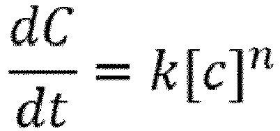
- In an embodiment of the present disclosure, the separator system (100) performs dehydroxylation of isolated SiOH groups, geminal SiOH groups and vicinal SiOH groups. The dehydroxylation of isolated SiOH groups, geminal SiOH groups and vicinal SiOH groups is defined by rate law
- In an embodiment of the present disclosure, the fumed silica particles undergoes separation and dehydroxylation in a time period. The time period for separation and dehydroxylation of the fumed silica particles depends upon one or more factors.
- In an aspect, the present disclosure provides a method. The method performs separation of fumed silica particles. The method includes a first step to collect a primary feed of fumed silica particles from a gaseous stream into a double entry cyclone from a first inlet. The method includes another step to collect a secondary feed of chlorine gas into the double entry cyclone from a second inlet. The method includes another step to treat the primary feed of the fumed silica particles and the secondary feed of chlorine gas along with heat inside a main body of the double entry cyclone. The method includes another step to release the dehydrated fumed silica particles from a first outlet. The method includes another step to release the water molecules and other gases after performing separation of the fumed silica particles from a second outlet. The primary feed of fumed silica particles is collected in a fluidized (free flowing) state. The secondary feed of chlorine gas is collected to perform dehydroxylation of the fluidized (free flowing) fumed silica particles.
- In an embodiment of the present disclosure, the method includes another step to perform dehydroxylation of the fluidized (free flowing) fumed silica particles in a chamber. The dehydroxylation is performed after performing separation of the fumed silica particles in the double entry cyclone. The chamber is surrounded by one or more induction furnaces.
- In an embodiment of the present disclosure, the method includes another step to perform dehydroxylation of the fluidized (free flowing) fumed silica particles in one or more chambers. The dehydroxylation is performed after performing separation of the fumed silica particles in the double entry cyclone. The one or more chambers are surrounded by one or more induction furnaces.
- In an embodiment of the present disclosure, the method includes another step to perform compaction of the fluidized (free flowing) fumed silica particles using a punch and a die apparatus. The compaction is performed after performing separation of the fumed silica particles in the double entry cyclone. The compaction is performed for performing dehydroxylation of compacted fumed silica particles.
- Having thus described the disclosure in general terms, reference will now be made to the accompanying figures, wherein:
-
FIG. 1 illustrates a three dimensional view of a system to perform separation and dehydroxylation of fumed silica particles, in accordance with various embodiments of the present disclosure; -
FIG. 2 illustrates a two dimensional view of the separator system to perform separation and dehydroxylation of fumed silica particles, in accordance with various embodiments of the present disclosure; -
FIG. 3 illustrates a general overview of a chamber to perform dehydroxylation of fluidized (free flowing) fumed silica particles, in accordance with various embodiments of the present disclosure; -
FIG. 4 illustrates a general overview of one or more chambers to perform dehydroxylation of fluidized (free flowing) fumed silica particles, in accordance with various embodiments of the present disclosure; and -
FIG. 5 illustrates a general overview of a mold assembly to perform compaction of fluidized (free flowing) fumed silica particles, in accordance with various embodiments of the present disclosure. - It should be noted that the accompanying figures are intended to present illustrations of exemplary embodiments of the present disclosure. These figures are not intended to limit the scope of the present disclosure. It should also be noted that accompanying figures are not necessarily drawn to scale.
- The following detailed description is of the best currently contemplated modes of carrying out exemplary embodiments of the invention. The description is not to be taken in a limiting sense, but is made merely for the purpose of illustrating the general principles of the invention.
- Reference will now be made in detail to selected embodiments of the present disclosure in conjunction with accompanying figures. The embodiments described herein are not intended to limit the scope of the disclosure, and the present disclosure should not be construed as limited to the embodiments described. This disclosure may be embodied in different forms without departing from the scope and spirit of the disclosure. It should be understood that the accompanying figures are intended and provided to illustrate embodiments of the disclosure described below and are not necessarily drawn to scale. In the drawings, like numbers refer to like elements throughout, and thicknesses and dimensions of some components may be exaggerated for providing better clarity and ease of understanding.
- Moreover, although the following description contains many specifics for the purposes of illustration, anyone skilled in the art will appreciate that many variations and/or alterations to said details are within the scope of the present technology. Similarly, although many of the features of the present technology are described in terms of each other, or in conjunction with each other, one skilled in the art will appreciate that many of these features can be provided independently of other features. Accordingly, this description of the present technology is set forth without any loss of generality to, and without imposing limitations upon, the present technology.
- It should be noted that the terms "first", "second", and the like, herein do not denote any order, ranking, quantity, or importance, but rather are used to distinguish one element from another. Further, the terms "a" and "an" herein do not denote a limitation of quantity, but rather denote the presence of at least one of the referenced items.
-
FIG. 1 illustrates a general overview of aseparator system 100 to perform separation and dehydroxylation of fumed silica particles, in accordance with various embodiments of the present disclosure.FIG. 2 illustrates a two dimensional view of theseparator system 100 to perform separation and dehydroxylation of fumed silica particles, in accordance with various embodiments of the present disclosure. Theseparator system 100 performs separation and separation of the fumed silica particles. Theseparator system 100 includes afirst inlet 102, and asecond inlet 104. In addition, theseparator system 100 includes amain body 106 of a double entry cyclone, afirst outlet 108 and asecond outlet 110. - In general, silica particles are white flaky substance consisting largely of silica, used in manufacturing of optical fiber preforms. In general, dehydroxylation is loss or removal of water from something. In addition, dehydroxylation involves heating process through which hydroxyl group (OH) is released by forming water molecule.
- The
separator system 100 includes thefirst inlet 102. Thefirst inlet 102 is utilized to collect a primary feed of fumed silica particles from a gaseous stream into the double entry cyclone. In an embodiment of the present disclosure, the primary feed comes from particle generation system. In addition, the primary feed contains the fumed silica particles and other gases. Thefirst inlet 102 collects the primary feed of silica particles in a fluidized (free flowing) state. In an embodiment of the present disclosure, thefirst inlet 102 passes the primary feed of the fumed silica particles inside themain body 106 of the double entry cyclone. - The
separator system 100 includes thesecond inlet 104. Thesecond inlet 104 is utilized to collect a secondary feed of chlorine gas into the double entry cyclone. Thesecond inlet 104 collects the secondary feed of chlorine gas to perform dehydroxylation of fluidized (free flowing) fumed silica particles. In an embodiment of the present disclosure, thesecond inlet 104 passes the secondary feed of the fumed silica particles inside themain body 106 of the double entry cyclone. - In an embodiment of the present disclosure, the
first inlet 102 collects the secondary feed of chlorine gas into the double entry cyclone. In an embodiment of the present disclosure, thesecond inlet 104 collects the primary feed of the fumed silica particles from the gaseous stream into the double entry cyclone. In other words, thefirst inlet 102 and thesecond inlet 104 may operate interchangeably. - In an embodiment of the present disclosure, the primary inlet creates a suction pressure to collect the primary feed of fumed silica particles into the double entry cyclone. In an embodiment of the present disclosure, the secondary inlet creates a suction pressure to collect the secondary feed of chlorine gas into the double entry cyclone. In an embodiment of the present disclosure, the
first inlet 102 includes a plurality of nozzles to shower the primary feed of fumed silica particles into the double entry cyclone. In an embodiment of the present disclosure, thesecond inlet 104 includes the plurality of nozzles to shower the secondary feed of chlorine gas into the double entry cyclone. - The
separator system 100 includes themain body 106 of the double entry cyclone. Themain body 106 of the double entry cyclone is utilized to treat the primary feed of the silica particles and the secondary feed of chlorine gas along with heat inside the double entry cyclone. In addition, the double entry cyclone imparts centrifugal force on the fluidized (free flowing) fumed silica particles to perform dehydroxylation and separation of the fumed silica particles. In an embodiment of the present disclosure, the double entry cyclone has higher temperature due to resistance heating. In general, resistance heating is defined as heat produced by passing an electric current through a material that preferably has high resistance. In another embodiment of the present disclosure, the double entry cyclone has higher temperature due to induction. In addition, the double entry cyclone is insulated to prevent leakage of heat from the double entry cyclone. - In an embodiment of the present disclosure, the vortex formation is result of design of the double entry cyclone. The primary inlet and the secondary inlet collects the primary feed and the secondary feed tangentially such that they result in the vortex formation inside the double entry cyclone. In an embodiment of the present disclosure, primary inlet feed tangentially such that they result in the vortex formation inside the double entry cyclone and secondary inlet feed perpendicular to the primary flow. In an embodiment of the present disclosure, secondary inlet feed tangentially such that they result in the vortex formation inside the double entry cyclone and primary inlet feed perpendicular to the primary flow. In an embodiment of the present disclosure, particulate formed after treatment of the primary feed of the fumed silica particles and the secondary feed of chlorine gas is collected in a hopper.
- The
separator system 100 includes thefirst outlet 108. Thefirst outlet 108 is utilized to release SiO2 particles. Thefirst outlet 108 is utilized to release dehydrated fumed silica particles. Further, theseparator system 100 includes thesecond outlet 110. Thesecond outlet 110 is utilized to release water molecules and other gases after performing separation and dehydroxylation of the fumed silica particles. The other gases include HCI, Nitrogen, air and the like. - The fumed silica particles undergoes dehydroxylation to remove physiosorbed water molecules and chemisorbed water molecules. In general, water associated with silica is in one of two forms. The two forms includes pysiosorbed water molecules and chemisorbed water molecules. Further, the chemisorbed water molecules includes but may not be limited to vicinal silanols, geminal silanols, and isolated silanols. The physiosorbed water molecules are removed at temperature of about 200° Celsius. The chemisorbed water molecules are removed at temperature greater than 200° Celsius. In an embodiment of the present disclosure, the chemisorbed water molecules remaining after temperature of 200° Celsius is in a range of about 30 parts per million to 50 parts per million. In another embodiment of the present disclosure, the range of the chemisorbed water molecules remaining after temperature of 200° Celsius may vary. In an embodiment of the present disclosure, the chemisorbed water molecules remaining after temperature of 200° Celsius is given by αOH in a range of 4.6 per nm2 to 4.9 per nm2.
- The physiosorbed water molecules are removed by treating the fumed silica particles up to temperature of about 200° Celsius. The chemisorbed water molecules are removed by treating the fumed silica particles above temperature of 200° Celsius. In addition, there is a possibility of rehydration of the water molecules up to temperature in a range of about 400° Celsius to 500° Celsius.
- The dehydroxylation of the fumed silica particles takes place in presence of the chlorine gas. The dehydroxylation of isolated SiOH groups, geminal SiOH groups and vicinal SiOH groups is defined by rate law

- The fumed silica particles undergoes separation and dehydroxylation in a time period. The time period for separation and dehydroxylation of the fumed silica particles depends upon one or more factors. The one or more factors include porosity of the fumed silica particles, geometry of the fumed silica particles, quantity of the fumed silica particles, temperature inside the double entry cyclone, the size of the cyclone, and the like. In an embodiment of the present disclosure, the time period required for dehydroxylation of the fumed silica particles depends on diffusion of chlorine in the silica silica.
- In an example, the dehydroxylation of the water molecules from concentration of 30 parts per million at a temperature of 200° Celsius to concentration of 0.1 parts per million for a given geometry and density takes place in time period of about 2 hours when treated at temperature of about 1100° Celsius. In another example, the time period required for dehydration of the fluidized (free flowing) silica particles of given mass is in a range of about 10 minutes to 15 minutes. In another example, the time period required for dehydration of the fluidized (free flowing) silica particles depends on particles flowing length inside the cyclone. In addition, the time taken for thermal diffusion depends on density and geometry of optical fiber preform.
- In an embodiment of the present disclosure, the dehydrated fumed silica particles from the
first outlet 108 of the double entry cyclone are stored in a storage tank. The dehydrated fumed silica particles are stored into the storage tank at a flow rate of about 500 grams per minute. In an embodiment of the present disclosure, the dehydrated fumed silica particles are stored into the storage tank at any suitable flow rate. -
FIG. 3 illustrates ageneral overview 300 of achamber 302 to perform dehydroxylation of fluidized (free flowing) fumed silica particles, in accordance with various embodiments of the present disclosure. Thechamber 302 is placed below thestorage tank 304 placed below thefirst outlet 108 of the double entry cyclone. In an embodiment of the present disclosure, thechamber 302 is utilized to perform dehyroxylation of the fluidized (free flowing) fumed silica particles. The dehydroxylation is performed after performing separation of the fumed silica particles in the double entry cyclone. Thechamber 302 is surrounded by one or more induction furnaces. The one or more induction furnaces provide heat to thechamber 302. - In an embodiment of the present disclosure, the
chamber 302 has height of 7 meter. In another embodiment of the present disclosure, height of thechamber 302 may vary. In an embodiment of the present disclosure, thechamber 302 has radius of 10.2 centimeter. In another embodiment of the present disclosure, radius of thechamber 302 may vary. In an embodiment of the present disclosure, thechamber 302 is made of quartz. In another embodiment of the present disclosure, thechamber 302 is made of any other suitable material of the like. In an example, thechamber 302 is capable to treat the fumed silica particles up to weight of 25 kilogram continuously for one hour. In an another example thechamber 302 may be suitably modified to treat the fumed silica particles up to any defined weight for a predetermined time. -
FIG. 4 illustrates ageneral overview 400 of one ormore chambers 302 to perform dehydroxylation of free flowing fumed silica particles, in accordance with various embodiments of the present disclosure. The one ormore chambers 302 are placed below thestorage tank 304 placed below thefirst outlet 108 of the double entry cyclone. In another embodiment of the present disclosure, the dehydroxylation is performed after performing separation of the fumed silica particles in the double entry cyclone. The one ormore chambers 302 are surrounded by one or more induction furnaces. In addition, each chamber of the one ormore chambers 302 is surrounded by the one or more induction furnaces. The one or more induction furnaces provide heat to the one ormore chambers 302. - In an embodiment of the present disclosure, each chamber of the one or
more chambers 302 has a height of 2 meter. In another embodiment of the present disclosure, height of each chamber of the one ormore chambers 302 may vary. In an embodiment of the present disclosure, each chamber of the one ormore chambers 302 has radius of 8.5 centimeter. In another embodiment of the present disclosure, radius of each chamber of the one ormore chambers 302 may vary. In an embodiment of the present disclosure, each chamber of the one ormore chambers 302 is made of quartz. In another embodiment of the present disclosure, each chamber of the one ormore chambers 302 is made of any other suitable material of the like. In an example, the one ormore chambers 302 are capable to treat the fumed silica particles up to weight of 5 kilogram continuously for one hour. In an another example the one ormore chambers 302 may be suitably modified to treat the fumed silica particles up to any defined weight for a predetermined time. -
FIG. 5 illustrates a general overview of amold assembly 500 to perform compaction of fluidized fumedsilica particles 502, in accordance with various embodiments of the present disclosure. The fluidized fumedsilica particles 502 are separated silica particles released from thefirst outlet 108 ofFIG. 1 . Themold assembly 500 includes a punchingmachine 504, apressing die 506 and a cylindrical shapedrod 508. The punching machine and the pressing die represent a punch and a die apparatus. The punch and the die apparatus is used to perform compaction of the fluidized fumedsilica particles 502. The fluidized fumedsilica particles 502 are low porosity with the defined geometry fumed silica particles. The dehydroxylation of the low porosity with the defined geometry fumed silica particles is achieved after compaction. The compaction is performed after performing separation of the fumed silica particles in the double entry cyclone (as shown inFIG. 1 andFIG. 2 ). In addition, the compaction is performed for performing dehydroxylation of compacted fumed silica particles. - The fluidized fumed
silica particles 502 are compacted using themold assembly 500 to manufacture compact silica particles. object. In addition, the compacted object is sintered to manufacture a clad preform. Themold assembly 500 performs pressing of the fluidized fumedsilica particles 502. The pressing of the fluidized fumedsilica particles 502 is a compaction of the fluidized fumedsilica particles 502 to manufacture the compact object as preform. - The
mold assembly 500 includes thepressing die 506. In general, die is a specialized tool used in manufacturing industries to cut or shape material, mostly using a press. In addition, dies are customized according to shape and size of target products. In an embodiment of the present disclosure, cross-section of thepressing die 506 is cylindrical. Thepressing die 506 is used for manufacturing of the compact object of cylindrical shape. In an embodiment of the present disclosure, thepressing die 506 has a cylindrical shape cavity at a central position. In an embodiment of the present disclosure, the cylindrical shape cavity is on upper surface of thepressing die 506 for positioning of the cylindrical shapedrod 508. - In an embodiment of the present disclosure, the cylindrical shaped
rod 508 is a mold rod used for manufacturing of hollow compact object. In an embodiment of the present disclosure, the length of the cylindrical shapedrod 508 is defined according to required length of the clad preform. - In an embodiment of the present disclosure, the
pressing die 506 has cavity around the cylindrical shapedrod 508. The shape and size of the cavity around the cylindrical shapedrod 508 is defined according to the shape and size of the required clad preform. In an embodiment of the present disclosure, thepressing die 506 has a first wall and a second wall. The first wall is an inner wall of thepressing die 506. The fluidized fumedsilica particles 502 are loaded in between the cylindrical shapedrod 508 and inner wall of thepressing die 506. - The fluidized fumed
silica particles 502 are loaded inside the cavity of thepressing die 506 from thestorage tank 304. In an embodiment of the present disclosure, the cavity of thepressing die 506 is cylindrical in shape. The fluidized fumedsilica particles 502 are loaded inside the cavity of thepressing die 506 based on the required size of the clad preform. - The fluidized fumed
silica particles 502 present inside the cavity of thepressing die 506 are pressed using the punchingmachine 504. The punchingmachine 504 is a machine tool for punching or pressing of the fluidized fumedsilica particles 502 to convert the fluidized fumedsilica particles 502 into the compact object. In an embodiment of the present disclosure, the punchingmachine 504 is one of automatic machine or manual machine. In another embodiment of the present disclosure, the punchingmachine 504 works on hydraulic press. The fluidized fumedsilica particles 502 are axially compressed or pressed to form the compact object around the cylindrical shapedrod 508. The punchingmachine 504 is used to apply pressure on the fluidized fumedsilica particles 502 to form the compact object. The pressure is applied towards the pressing die 506 to press the fluidized fumedsilica particles 502. In addition, the pressure is applied to press the fluidized fumedsilica particles 502 to form the compact object of target density. - In an embodiment of the present disclosure, the fluidized fumed
silica particles 502 are pressed using cold press technique. In general, cold press technique refers to the pressing of the dehydrated silica particles in mold assembly below sintering temperature or at room temperature. The cold pressing of the fluidized fumedsilica particles 502 is performed to provide proper shape and density to the required clad preform. - In another embodiment of the present disclosure, the fluidized fumed
silica particles 502 are pressed using hot press technique. In general, hot press technique refers to pressing of dehydrated silica particles using heated pressing die. In an embodiment of the present disclosure, themold assembly 500 is enclosed inside one or more furnaces to increase temperature for pressing of the fluidized fumedsilica particles 502. The one or more furnaces enables heating of thepressing die 506 for manufacturing of the compact object. In an embodiment of the present disclosure, thepressing die 506 is heated using radiation or convection to reach the desired temperature for the compaction of the fluidized fumedsilica particles 502. In another embodiment of the present disclosure, thepressing die 506 is heated using induction or resistance techniques. In yet another embodiment of the present disclosure, thepressing die 506 is heated using any other suitable technique of the like. In an embodiment of the present disclosure, uniaxial pressing is done for the compaction of the fluidized fumedsilica particles 502 in the heatedpressing die 506. In another embodiment of the present disclosure, isostatic pressing is done for the compaction of the fluidized fumedsilica particles 502 in the heatedpressing die 506. The uniaxial pressing or isostatic pressing is done for the manufacturing of the compact object. - In an embodiment of the present disclosure, the compaction of the fluidized fumed
silica particles 502 results in the decrease in volume and increase in density of the compact object. In an embodiment of the present disclosure, an inward pressure is applied on the fluidized fumedsilica particles 502 to form the compact object. In an embodiment of the present disclosure, the punchingmachine 504 uniformly presses the fluidized fumedsilica particles 502 from one or more sides of thepressing die 506. - The
mold assembly 500 enables conversion of the fluidized fumedsilica particles 502 into the cylindrical shape compact object. In addition, thepressing die 506 along with the punchingmachine 504 enable the conversion of the fluidized fumedsilica particles 502 into the compact object with defined or target density. - In an embodiment of the present disclosure, the cylindrical shaped
rod 508 is inserted into themold assembly 500 for the formation of the hollow cylindrical shaped compact object. The hollow cylindrical shaped compact object is sintered for the formation of the hollow cylindrical shaped clad preform. In an embodiment of the present disclosure, the hollow cylindrical shaped compact object is sintered in a sintering furnace for the formation of the hollow cylindrical shaped clad preform. In general, sintering refers to a process of forming a glass preform or clad preform from the compacted object with facilitation of heat without melting compacted object to point of liquefaction. In an example, the hollow cylindrical shaped clad preform has a porosity of about 0.5. In another example, porosity of the hollow cylindrical shaped clad preform may vary. In general, porosity refers to bulk density of hollow cylindrical shape. - In an embodiment of the present disclosure, the double entry cyclone separator performs both separation and dehydroxylation of the fumed silica particles. In another embodiment of the present disclosure, the double entry cyclone separator performs dehydroxylation of the fumed silica particles. In an embodiment of the present disclosure, the dehydroxylation of the fumed silica particles is performed at a high temperature. In yet another embodiment of the present disclosure, the double entry cyclone separator performs only separation of the fumed silica particles. In that case, the dehydroxylation of the fumed silica particles is performed in the chamber (as shown in
FIG. 3 ), in the one or more chambers (as shown inFIG. 4 ), or after compaction of the fluidized fumed silica particles (as shown inFIG. 5 ). - The foregoing descriptions of pre-defined embodiments of the present technology have been presented for purposes of illustration and description. They are not intended to be exhaustive or to limit the present technology to the precise forms disclosed, and obviously many modifications and variations are possible in light of the above teaching. The embodiments were chosen and described in order to best explain the principles of the present technology and its practical application, to thereby enable others skilled in the art to best utilize the present technology and various embodiments with various modifications as are suited to the particular use contemplated. It is understood that various omissions and substitutions of equivalents are contemplated as circumstance may suggest or render expedient, but such are intended to cover the application or implementation without departing from the spirit or scope of the claims of the present technology.
Claims (13)
- A method for performing separation of fumed silica particles, the method comprising:collecting a primary feed of fumed silica particles from a gaseous stream, wherein the primary feed of fumed silica particles is collected in a fluidized state;collecting a secondary feed of chlorine gas, wherein the secondary feed of chlorine gas is collected for performing separation of the fluidized fumed silica particles;treating the primary feed of the fumed silica particles and the secondary feed of chlorine gas along with heat; andreleasing the dehydrated fumed silica particles from a first outlet (108), whereby separating the fumed silica particles.
- The method as recited in claim 1, wherein the primary feed of fumed silica particles from a gaseous stream is collected into a double entry cyclone from a first inlet (102).
- The method as recited in claim 1 or claim 2, wherein collecting the secondary feed of chlorine gas into the double entry cyclone from a second inlet (104).
- The method as recited in any preceding claim, further comprising, after performing separation of the fumed silica particles, releasing water molecules and gases from a second outlet (110).
- A separator system (100) for performing separation and dehydroxylation of fumed silica particles, the separator system (100) comprising:a first inlet (102), wherein the first inlet (102) is utilized for collecting a primary feed of fumed silica particles from a gaseous stream into a double entry cyclone, wherein the primary feed of fumed silica particles is collected in a fluidized state;a second inlet (104), wherein the second inlet (104) is utilized for collecting a secondary feed of chlorine gas into the double entry cyclone, wherein the secondary feed of chlorine gas is collected for performing dehydroxylation of the fluidized fumed silica particles;a main body (106) of the double entry cyclone, wherein the main body (106) of the double entry cyclone is utilized in treating the primary feed of the fumed silica particles and the secondary feed of chlorine gas along with heat inside the double entry cyclone;a first outlet (108), wherein the first outlet (108) is utilized for releasing the dehydrated fumed silica particles; anda second outlet (110), wherein the second outlet (110) is utilized for releasing the water molecules and other gases after performing separation and dehydroxylation of the fumed silica particles.
- The separator system (100) as recited in claim 5, wherein the vortex formation imparts centrifugal force on the fluidized fumed silica particles and the separation and dehydroxylation of the fumed silica particles happens for releasing dehydrated fumed silica particles and water molecules.
- The separator system (100) as recited in claim 5 or claim 6, wherein the fumed silica particles undergoes dehydroxylation for removing physiosorbed water molecules and chemisorbed water molecules, wherein the chemisorbed water molecules are removed after removal of the physiosorbed water molecules, wherein the physiosorbed water molecules are removed at temperature of about 200° Celsius, wherein the chemisorbed water molecules remaining after temperature of 200° Celsius is in range of about 30 parts per million to 50 parts per million.
- The separator system (100) as recited in any one of claims 5 to 7, wherein the separator system (100) performs dehydroxylation of isolated SiOH groups, geminal SiOH groups and vicinal SiOH groups, wherein the dehydroxylation of isolated SiOH groups, geminal SiOH groups and vicinal SiOH groups is defined by rate law

- The separator system (100) as recited in any one of claims 5 to 8, wherein the fumed silica particles undergoes separation and dehydroxylation in a time period, wherein the time period for separation and dehydroxylation of the fumed silica particles depends upon one or more factors.
- A method for performing separation of fumed silica particles, the method comprising:collecting, a primary feed of fumed silica particles from a gaseous stream into a double entry cyclone from a first inlet (102), wherein the primary feed of fumed silica particles is collected in a fluidized state;collecting, a secondary feed of chlorine gas into the double entry cyclone from a second inlet (104), wherein the secondary feed of chlorine gas is collected for performing separation of the fluidized fumed silica particles;treating, the primary feed of the fumed silica particles and the secondary feed of chlorine gas along with heat inside a main body (106) of the double entry cyclone;releasing, the dehydrated fumed silica particles from a first outlet (108); andreleasing, the water molecules and other gases after performing separation of the fumed silica particles from a second outlet (110).
- The method as recited in claim 10, further comprising, performing dehydroxylation of the fluidized fumed silica particles in a chamber (302), wherein the dehydroxylation is performed after performing separation of the fumed silica particles in the double entry cyclone, wherein the chamber (302) is surrounded by one or more induction furnaces.
- The method as recited in claim 10 or claim 11, further comprising, performing dehydroxylation of the fluidized fumed silica particles in one or more chambers (302), wherein the dehydroxylation is performed after performing separation of the fumed silica particles in the double entry cyclone, wherein the one or more chambers (302) are surrounded by one or more induction furnaces.
- The method as recited in any one of claims 10 to 12, further comprising, performing compaction of the fluidized fumed silica particles using a punch and a die apparatus, wherein the compaction is performed after performing separation of the fumed silica particles in the double entry cyclone, wherein the compaction is performed for performing dehydroxylation of compacted fumed silica particles.
Applications Claiming Priority (1)
| Application Number | Priority Date | Filing Date | Title |
|---|---|---|---|
| IN201921032781 | 2019-08-13 |
Publications (1)
| Publication Number | Publication Date |
|---|---|
| EP3782723A1 true EP3782723A1 (en) | 2021-02-24 |
Family
ID=72087889
Family Applications (1)
| Application Number | Title | Priority Date | Filing Date |
|---|---|---|---|
| EP20191015.5A Pending EP3782723A1 (en) | 2019-08-13 | 2020-08-13 | System and method for performing separation and dehydroxylation of fumed silica soot particles |
Country Status (3)
| Country | Link |
|---|---|
| US (2) | US20210047189A1 (en) |
| EP (1) | EP3782723A1 (en) |
| CN (1) | CN112390261A (en) |
Families Citing this family (1)
| Publication number | Priority date | Publication date | Assignee | Title |
|---|---|---|---|---|
| US12617707B2 (en) * | 2023-03-29 | 2026-05-05 | Sterlite Technologies Limited | Optical fiber and a glass preform manufacturing method |
Citations (6)
| Publication number | Priority date | Publication date | Assignee | Title |
|---|---|---|---|---|
| US3859420A (en) * | 1969-12-18 | 1975-01-07 | Degussa | Process of making super-dry silicon dioxide |
| WO1988003914A1 (en) * | 1986-11-20 | 1988-06-02 | Tsl Group Plc | Vitreous silica |
| US20060049082A1 (en) * | 2004-09-09 | 2006-03-09 | Kellogg Brown And Root, Inc. | Self-stripping fcc riser cyclone |
| US20060230995A1 (en) * | 2004-10-22 | 2006-10-19 | Ulrich Muschelknautz | Method and installation for regulating the quantity of circulating solids in a circulating fluidized bed reactor system |
| US20100107700A1 (en) * | 2008-10-30 | 2010-05-06 | Steven Bruce Dawes | Methods For Forming Cladding Portions Of Optical Fiber Preform Assemblies |
| WO2015114401A1 (en) * | 2014-01-31 | 2015-08-06 | Exxonmobil Chemical Patents Inc. | Fluid separation systems and methods |
Family Cites Families (58)
| Publication number | Priority date | Publication date | Assignee | Title |
|---|---|---|---|---|
| US2607438A (en) * | 1948-06-30 | 1952-08-19 | Standard Oil Dev Co | Cyclone separator |
| US2967618A (en) * | 1960-03-28 | 1961-01-10 | Vane Zdenek | Vortical separator |
| US3150943A (en) * | 1960-10-27 | 1964-09-29 | Gen Electric | Cyclone-type dust collector |
| US3064811A (en) * | 1961-05-18 | 1962-11-20 | Combustion Eng | Method and apparatus for inerting fuel separation cyclone against spontaneous combustion |
| US3645684A (en) * | 1970-07-01 | 1972-02-29 | Cities Service Co | Fractionation of silica aerosols |
| SE340272B (en) * | 1971-01-19 | 1971-11-15 | Kema Nord Ab | |
| US4036933A (en) * | 1974-01-18 | 1977-07-19 | Deutsche Gold- Und Silber-Scheideanstalt Vormals Roessler | Highly-active, finely divided super-dry silicon dioxide |
| JPS5410598Y2 (en) * | 1974-10-31 | 1979-05-16 | ||
| US4004898A (en) * | 1976-01-30 | 1977-01-25 | Emtrol Corporation | Cyclone separator gas tube heat dissipator |
| US4043899A (en) * | 1976-02-27 | 1977-08-23 | Mobil Oil Corporation | Method and means for separating gasiform materials from finely divided catalyst particles |
| US4146359A (en) * | 1976-06-25 | 1979-03-27 | Occidental Petroleum Corporation | Method for reacting nongaseous material with a gaseous reactant |
| US4089631A (en) * | 1976-09-23 | 1978-05-16 | General Electric Company | Coal-burning gas turbine combustion system for reducing turbine erosion |
| US4212653A (en) * | 1978-06-27 | 1980-07-15 | General Electric Company | Process and apparatus for separating particulate matter from gaseous media |
| US4670410A (en) * | 1981-06-22 | 1987-06-02 | Atlantic Richfield Company | Method for reducing attrition of particulate matter in a chemical conversion process |
| GB2159072A (en) * | 1983-10-06 | 1985-11-27 | Noel Carroll | Cyclone separator |
| US4960525A (en) * | 1988-09-26 | 1990-10-02 | The United States Of America, As Represented By The Secretary Of Agriculture | Hydrocyclone for washing particles in liquid suspension |
| US4944250A (en) * | 1989-03-30 | 1990-07-31 | Foster Wheeler Energy Corporation | Cyclone separator including a hopper formed by water-steam cooled walls |
| WO1991001207A1 (en) * | 1989-07-18 | 1991-02-07 | Exxon Chemical Patents Inc. | Method and apparatus for centrifugal cooling and treating of solids in dilute phase solid-gas systems |
| US4961761A (en) * | 1989-08-18 | 1990-10-09 | Foster Wheeler Energy Corporation | Cyclone separator wall refractory material system |
| GB2239191B (en) * | 1989-11-28 | 1993-04-14 | Orkney Water Test Centre Limit | A method of coalescing a disperse phase within a continuous phase of a fluid mixture |
| US5116394A (en) * | 1991-03-25 | 1992-05-26 | Foster Wheeler Energy Corporation | Cyclone separator roof |
| SE508561C2 (en) * | 1991-07-16 | 1998-10-12 | Kvaerner Pulping Tech | Method and apparatus for separating particles from a gas stream |
| US5203284A (en) * | 1992-03-02 | 1993-04-20 | Foster Wheeler Development Corporation | Fluidized bed combustion system utilizing improved connection between the reactor and separator |
| AT404912B (en) * | 1996-11-04 | 1999-03-25 | Plansee Ag | METHOD FOR PRODUCING POWDER PRESSING APPARATUS FOR FINE-GRAINED HARD METAL |
| US5935528A (en) * | 1997-01-14 | 1999-08-10 | Molten Metal Technology, Inc. | Multicomponent fluid feed apparatus with preheater and mixer for a high temperature chemical reactor |
| US5855652A (en) * | 1997-01-31 | 1999-01-05 | Topaz 2000, Inc. | Aerosol collector and concentrator |
| US6267803B1 (en) * | 1997-06-26 | 2001-07-31 | International Paper Company | Abrasive wear barrier |
| AU8272701A (en) * | 2000-08-29 | 2002-03-13 | Eco Technology Internat 2000 L | Milling and drying apparatus incorporating a cyclone |
| US20060157899A1 (en) * | 2005-01-15 | 2006-07-20 | Lew Holdings, Llc | Single vessel blast furnace and steel making/gasifying apparatus and process |
| US20060222705A1 (en) * | 2005-03-31 | 2006-10-05 | Flanner Henry H | Pharmaceutical tablet and apparatus and method for making |
| DE602006019600D1 (en) * | 2005-06-29 | 2011-02-24 | Danieli Corus Technical Services B V | CYCLONE SEPARATOR FOR HIGH FUEL GAS |
| EP2089128A4 (en) * | 2006-12-08 | 2013-04-17 | Spectra Analysis Instr Inc | Method and apparatus for desolvating flowing liquid |
| EE05544B1 (en) * | 2007-09-05 | 2012-06-15 | Aktsiaselts Narva ?Litehas | Dust extraction chamber for separating solid particles from a vapor-gas mixture |
| US9445488B2 (en) * | 2007-10-16 | 2016-09-13 | Foret Plasma Labs, Llc | Plasma whirl reactor apparatus and methods of use |
| US8245532B2 (en) * | 2008-05-15 | 2012-08-21 | Concepts Eti, Inc. | Semi-closed air-cycle refrigeration system and a positive-pressure snow removal cyclone separator therefor |
| BRPI0803051B1 (en) * | 2008-06-30 | 2019-01-15 | Petróleo Brasileiro S/A - Petrobras | gas-solid suspension cyclonic separator and separation method |
| US8398751B2 (en) * | 2008-07-17 | 2013-03-19 | Kellogg Brown & Root Llc | Direct stripping cyclone |
| US7854908B2 (en) * | 2008-08-20 | 2010-12-21 | Hnat James G | Method and apparatus for the recovery of molybdenum from spent catalysts |
| MY158448A (en) * | 2010-02-24 | 2016-10-14 | Univation Tech Llc | Apparatus and methods for separating volatiles from particulates |
| US8419835B2 (en) * | 2010-08-10 | 2013-04-16 | Uop Llc | Apparatuses and methods for gas-solid separations using cyclones |
| EP2457646A1 (en) * | 2010-11-26 | 2012-05-30 | Enefit Outotec Technology Oü | Separator for separating solid particles from a vapour-gas mixture |
| GB201106573D0 (en) * | 2011-04-19 | 2011-06-01 | Siemens Vai Metals Tech Ltd | Cyclone |
| FI123720B (en) * | 2011-10-17 | 2013-10-15 | Maricap Oy | Separation device and method in connection with a pneumatic material transport system |
| US9266123B2 (en) * | 2013-12-05 | 2016-02-23 | Exxonmobil Research And Engineering Company | Integrated cyclone assembly |
| EP3081279A4 (en) * | 2013-12-09 | 2017-11-01 | Sui Chun Law | Air purification apparatus and method |
| FI126040B (en) * | 2014-07-09 | 2016-06-15 | Amec Foster Wheeler En Oy | Particle separator that can be connected to a fluidized bed reactor and fluidized bed reactor |
| EP2995788B1 (en) * | 2014-09-12 | 2019-06-26 | Rolls-Royce Corporation | Fuel cooled cyclonic air oil separator |
| EP3000525A1 (en) * | 2014-09-26 | 2016-03-30 | Doosan Lentjes GmbH | Fluidized bed reactor |
| EP3390307A2 (en) * | 2015-12-18 | 2018-10-24 | Heraeus Quarzglas GmbH & Co. KG | Reduction of the carbon content of silica granulate, and production of a silica glass article |
| CN107413285B (en) * | 2016-05-24 | 2021-09-07 | 英尼奥斯欧洲股份公司 | Ammoxidation reactor control |
| CN109906213B (en) * | 2016-09-22 | 2022-03-25 | 埃克森美孚化学专利公司 | Use of light gas by-products for the production of para-xylene by methylation of toluene and/or benzene |
| MY197197A (en) * | 2016-10-19 | 2023-05-31 | Dalian Inst Chem & Physics Cas | Fast fluidized-bed reactor, device, and method using oxygen-containing compound for manufacturing propene or c4 hydrocarbon |
| EP3600612A4 (en) * | 2017-03-22 | 2020-04-15 | University Of Delaware | CENTRIFUGAL EVAPORATION SOURCES |
| KR101736838B1 (en) * | 2017-04-20 | 2017-05-29 | 채재우 | Hybrid type combustion device using pyrolysis of water and combustion air |
| FR3066115B1 (en) * | 2017-05-10 | 2019-06-28 | Universite de Bordeaux | COMPRESSES OF NUCLEIC ACID VECTORS |
| US20190131066A1 (en) * | 2017-10-26 | 2019-05-02 | Ford Global Technologies, Llc | Grain boundary diffusion technology for rare earth magnets |
| US10238706B1 (en) * | 2017-12-14 | 2019-03-26 | MedReleaf Corp. | Condensible gas botanical extraction systems and methods |
| EP3747026A4 (en) * | 2018-01-30 | 2021-10-27 | Westinghouse Electric Company Llc | Grain boundary enhanced un and u3si2 pellets with improved oxidation resistance |
-
2020
- 2020-01-16 CN CN202010048193.3A patent/CN112390261A/en active Pending
- 2020-04-15 US US16/849,956 patent/US20210047189A1/en not_active Abandoned
- 2020-08-13 EP EP20191015.5A patent/EP3782723A1/en active Pending
-
2024
- 2024-06-04 US US18/732,805 patent/US12466737B2/en active Active
Patent Citations (6)
| Publication number | Priority date | Publication date | Assignee | Title |
|---|---|---|---|---|
| US3859420A (en) * | 1969-12-18 | 1975-01-07 | Degussa | Process of making super-dry silicon dioxide |
| WO1988003914A1 (en) * | 1986-11-20 | 1988-06-02 | Tsl Group Plc | Vitreous silica |
| US20060049082A1 (en) * | 2004-09-09 | 2006-03-09 | Kellogg Brown And Root, Inc. | Self-stripping fcc riser cyclone |
| US20060230995A1 (en) * | 2004-10-22 | 2006-10-19 | Ulrich Muschelknautz | Method and installation for regulating the quantity of circulating solids in a circulating fluidized bed reactor system |
| US20100107700A1 (en) * | 2008-10-30 | 2010-05-06 | Steven Bruce Dawes | Methods For Forming Cladding Portions Of Optical Fiber Preform Assemblies |
| WO2015114401A1 (en) * | 2014-01-31 | 2015-08-06 | Exxonmobil Chemical Patents Inc. | Fluid separation systems and methods |
Also Published As
| Publication number | Publication date |
|---|---|
| US12466737B2 (en) | 2025-11-11 |
| US20240327230A1 (en) | 2024-10-03 |
| US20210047189A1 (en) | 2021-02-18 |
| CN112390261A (en) | 2021-02-23 |
Similar Documents
| Publication | Publication Date | Title |
|---|---|---|
| US4501601A (en) | Process for manufacturing glass fiber optical waveguides | |
| CN1042825C (en) | Manufacturing method of large size quartz glass tube | |
| TWI565666B (en) | Method for producing a large-diameter quartz glass tube | |
| JP5997290B2 (en) | Compressed multilayer silica soot preform for manufacturing optical fibers with complex refractive index profiles in one sintering process | |
| EP2507180B1 (en) | Soot pressing for optical fiber overcladding | |
| US12466737B2 (en) | System and method for performing separation and dehydroxylation of fumed silica soot particles | |
| CN104045232A (en) | Methods For Forming Cladding Portions Of Optical Fiber Preform Assemblies | |
| CN110382426B (en) | Method for manufacturing optical fiber | |
| CN115231938A (en) | Preparation method of carbon/carbon composite material brake disc | |
| CN105873870B (en) | Method for manufacturing optical fiber preform and method for manufacturing optical fiber | |
| US20040194505A1 (en) | Method of making a photonic crystal preform | |
| EP3782960A1 (en) | Method for manufacturing of optical fibre preform | |
| CN112194359A (en) | Method for manufacturing glass preform | |
| NL8103648A (en) | METHOD FOR MANUFACTURING FORMS FOR DRAWING OPTICAL FIBERS AND FORMS ACCORDING TO THIS METHOD AND FOR APPARATUS FOR MANUFACTURING OPTICAL FIBERS | |
| CN103214180B (en) | The heat shield member of porous glass base material and sintering method | |
| EP1367028A3 (en) | A method for manufacturing a preform using a thermal treatment apparatus and preform obtained by the process | |
| Özkan et al. | Overall shape of sintered alumina compacts | |
| Torikai et al. | Quartz crystal reinforced silica glass obtained by spark plasma sintering | |
| CN103433322A (en) | Preparation method of elbow by hot pushing under intermediate frequency | |
| CN119977583B (en) | Preparation method and device of high-purity porous boron carbide core control rod | |
| CN112449612A (en) | Band-pass filter for separating a particular selected gas from a group of gases or the atmosphere | |
| RU2030368C1 (en) | Method for producing ceramic die with through channels | |
| EP0107428A2 (en) | Plasma processed sinterable ceramics | |
| EP3805165A1 (en) | Method for fabrication of optical fibre soot preform | |
| SU975613A1 (en) | Apparatus for making glass fiber |
Legal Events
| Date | Code | Title | Description |
|---|---|---|---|
| PUAI | Public reference made under article 153(3) epc to a published international application that has entered the european phase |
Free format text: ORIGINAL CODE: 0009012 |
|
| STAA | Information on the status of an ep patent application or granted ep patent |
Free format text: STATUS: THE APPLICATION HAS BEEN PUBLISHED |
|
| AK | Designated contracting states |
Kind code of ref document: A1 Designated state(s): AL AT BE BG CH CY CZ DE DK EE ES FI FR GB GR HR HU IE IS IT LI LT LU LV MC MK MT NL NO PL PT RO RS SE SI SK SM TR |
|
| AX | Request for extension of the european patent |
Extension state: BA ME |
|
| STAA | Information on the status of an ep patent application or granted ep patent |
Free format text: STATUS: REQUEST FOR EXAMINATION WAS MADE |
|
| 17P | Request for examination filed |
Effective date: 20210824 |
|
| RBV | Designated contracting states (corrected) |
Designated state(s): AL AT BE BG CH CY CZ DE DK EE ES FI FR GB GR HR HU IE IS IT LI LT LU LV MC MK MT NL NO PL PT RO RS SE SI SK SM TR |
|
| STAA | Information on the status of an ep patent application or granted ep patent |
Free format text: STATUS: EXAMINATION IS IN PROGRESS |
|
| 17Q | First examination report despatched |
Effective date: 20240116 |