EP3782679B1 - Injection needle and injection device - Google Patents
Injection needle and injection device Download PDFInfo
- Publication number
- EP3782679B1 EP3782679B1 EP19787708.7A EP19787708A EP3782679B1 EP 3782679 B1 EP3782679 B1 EP 3782679B1 EP 19787708 A EP19787708 A EP 19787708A EP 3782679 B1 EP3782679 B1 EP 3782679B1
- Authority
- EP
- European Patent Office
- Prior art keywords
- needle
- adjuster
- base
- injection needle
- injection
- Prior art date
- Legal status (The legal status is an assumption and is not a legal conclusion. Google has not performed a legal analysis and makes no representation as to the accuracy of the status listed.)
- Active
Links
Images









Classifications
-
- A—HUMAN NECESSITIES
- A61—MEDICAL OR VETERINARY SCIENCE; HYGIENE
- A61M—DEVICES FOR INTRODUCING MEDIA INTO, OR ONTO, THE BODY; DEVICES FOR TRANSDUCING BODY MEDIA OR FOR TAKING MEDIA FROM THE BODY; DEVICES FOR PRODUCING OR ENDING SLEEP OR STUPOR
- A61M5/00—Devices for bringing media into the body in a subcutaneous, intra-vascular or intramuscular way; Accessories therefor, e.g. filling or cleaning devices, arm rests
- A61M5/178—Syringes
- A61M5/28—Syringe ampoules or carpules, i.e. ampoules or carpules provided with a needle
-
- A—HUMAN NECESSITIES
- A61—MEDICAL OR VETERINARY SCIENCE; HYGIENE
- A61M—DEVICES FOR INTRODUCING MEDIA INTO, OR ONTO, THE BODY; DEVICES FOR TRANSDUCING BODY MEDIA OR FOR TAKING MEDIA FROM THE BODY; DEVICES FOR PRODUCING OR ENDING SLEEP OR STUPOR
- A61M5/00—Devices for bringing media into the body in a subcutaneous, intra-vascular or intramuscular way; Accessories therefor, e.g. filling or cleaning devices, arm rests
- A61M5/178—Syringes
- A61M5/31—Details
- A61M5/32—Needles; Details of needles pertaining to their connection with syringe or hub; Accessories for bringing the needle into, or holding the needle on, the body; Devices for protection of needles
- A61M5/3202—Devices for protection of the needle before use, e.g. caps
-
- A—HUMAN NECESSITIES
- A61—MEDICAL OR VETERINARY SCIENCE; HYGIENE
- A61M—DEVICES FOR INTRODUCING MEDIA INTO, OR ONTO, THE BODY; DEVICES FOR TRANSDUCING BODY MEDIA OR FOR TAKING MEDIA FROM THE BODY; DEVICES FOR PRODUCING OR ENDING SLEEP OR STUPOR
- A61M5/00—Devices for bringing media into the body in a subcutaneous, intra-vascular or intramuscular way; Accessories therefor, e.g. filling or cleaning devices, arm rests
- A61M5/178—Syringes
- A61M5/31—Details
- A61M5/32—Needles; Details of needles pertaining to their connection with syringe or hub; Accessories for bringing the needle into, or holding the needle on, the body; Devices for protection of needles
- A61M5/3286—Needle tip design, e.g. for improved penetration
-
- A—HUMAN NECESSITIES
- A61—MEDICAL OR VETERINARY SCIENCE; HYGIENE
- A61M—DEVICES FOR INTRODUCING MEDIA INTO, OR ONTO, THE BODY; DEVICES FOR TRANSDUCING BODY MEDIA OR FOR TAKING MEDIA FROM THE BODY; DEVICES FOR PRODUCING OR ENDING SLEEP OR STUPOR
- A61M5/00—Devices for bringing media into the body in a subcutaneous, intra-vascular or intramuscular way; Accessories therefor, e.g. filling or cleaning devices, arm rests
- A61M5/178—Syringes
- A61M5/31—Details
- A61M5/32—Needles; Details of needles pertaining to their connection with syringe or hub; Accessories for bringing the needle into, or holding the needle on, the body; Devices for protection of needles
- A61M5/329—Needles; Details of needles pertaining to their connection with syringe or hub; Accessories for bringing the needle into, or holding the needle on, the body; Devices for protection of needles characterised by features of the needle shaft
-
- A—HUMAN NECESSITIES
- A61—MEDICAL OR VETERINARY SCIENCE; HYGIENE
- A61M—DEVICES FOR INTRODUCING MEDIA INTO, OR ONTO, THE BODY; DEVICES FOR TRANSDUCING BODY MEDIA OR FOR TAKING MEDIA FROM THE BODY; DEVICES FOR PRODUCING OR ENDING SLEEP OR STUPOR
- A61M5/00—Devices for bringing media into the body in a subcutaneous, intra-vascular or intramuscular way; Accessories therefor, e.g. filling or cleaning devices, arm rests
- A61M5/178—Syringes
- A61M5/31—Details
- A61M5/32—Needles; Details of needles pertaining to their connection with syringe or hub; Accessories for bringing the needle into, or holding the needle on, the body; Devices for protection of needles
- A61M5/3295—Multiple needle devices, e.g. a plurality of needles arranged coaxially or in parallel
-
- A—HUMAN NECESSITIES
- A61—MEDICAL OR VETERINARY SCIENCE; HYGIENE
- A61M—DEVICES FOR INTRODUCING MEDIA INTO, OR ONTO, THE BODY; DEVICES FOR TRANSDUCING BODY MEDIA OR FOR TAKING MEDIA FROM THE BODY; DEVICES FOR PRODUCING OR ENDING SLEEP OR STUPOR
- A61M5/00—Devices for bringing media into the body in a subcutaneous, intra-vascular or intramuscular way; Accessories therefor, e.g. filling or cleaning devices, arm rests
- A61M5/46—Devices for bringing media into the body in a subcutaneous, intra-vascular or intramuscular way; Accessories therefor, e.g. filling or cleaning devices, arm rests having means for controlling depth of insertion
Definitions
- a male screw portion 33 is formed on the top end side (on the left of Fig. 4 ) of the needle base 21.
- the top and bottom ends of the male screw portion 33 as shown in Fig. 5 , have been cut off due to molding reasons. These cut-off portions are shown by reference signs 34, 34 in the drawings.
- there are projections 35, 35 protrusively formed, respectively, at positions opposing to each other at the angle of 180 degrees. Moreover, at the position somewhat closer to the rear (to the right of Fig.
- the protrusion length of the needles 23, 23, 23, 23 (as shown by reference sign L in Fig. 4 ), respectively, and eventually the puncture depth of the needles 23, 23, 23, 23, respectively, is adjusted.
- the adjuster 25 is positioned at the right end of Fig. 4 so that the base end thereof becomes in contact with the base-end side stoppers 37, 37, the protrusion length (L) of the needles 23, 23, 23, 23, respectively, is in the maximum length (L max ).
- each of the needles 23, 23, 23, 23 is in a state of being withdrawn from the top end of the adjuster 25, for example, at least about 1 to 3 mm inwardly.
- a needle-base side reference position marker 40a protrusively formed on the needle base 21, and there is also an adjuster side reference position marker 40b protrusively formed on the adjuster 25.
- the position in the rotative direction of the needle-base side reference position marker 40a and the position in the rotative direction of the adjuster side reference position marker 40b are set to match with each other, when the adjuster 25 is at the position closest to the base end side (a state as shown in Fig. 4 ).
- a cap 41 is crowned to be detachable on the top end side (on the left of Fig. 12 ) of the adjuster 25 of the injection needle 5.
- the medicinal solution is filled in the injection cylinder 7 of the syringe 3.
- the injection needle 5 is attached to the injection cylinder 7 of the syringe 3.
- the adjuster 25 is rotated counterclockwise as seen from the side facing to the direct front of the adjuster 25 at the left end in Fig. 1 to Fig. 4 , so as to move the adjuster 25 to the left of Fig. 1 to Fig. 4 at an appropriate amount, whereby the protrusion length (L) of each of the needles 23, 23, 23, 23, and eventually the puncture depth of each of the needles 23, 23, 23, 23, is adjusted arbitrarily.
- the side of the needles 23, 23, 23, 23 of the injection device 1 is oriented to the skin (not shown) as an object to be punctured, and the needles 23, 23, 23, 23 are punctured vertically against the skin.
- the top end surface of the adjuster 25 (the surface on the left of Fig. 1 to Fig. 4 ) becomes in contact with the skin, and the puncture is performed at a predetermined puncture depth.
- the plunger 9 of the syringe 3 is depressed to apply force toward the top end side (the left of Fig. 1 to Fig. 4 ), whereby the medicinal solution is injected.
- the needles 23, 23, 23, 23 are removed from the skin. Thereafter, the adjuster 25 is rotated counterclockwise as seen from the side facing to the direct front of the adjuster 25 at the left end in Fig. 1 to Fig. 4 , so as to move the adjuster 25 to the top end side (to the left of Fig. 1 to Fig. 4 ), and as illustrated in Fig. 10 , the top end side of each of the needles 23, 23, 23, 23 is retracted in the adjuster 25.
- the double-puncture (wrong puncture after completion of puncture) is prevented.
- the top end is covered by crowning of the cap 41, and the whole body of the injection device 1 is disposed as the waste in such a state. Otherwise, only the injection needle 5 is disposed as the waste, by detaching the injection needle 5 from the syringe 3.
- each of the needles 23, 23, 23, 23 can be retracted in the adjuster 25, and accordingly, even without the need of attachment of the cap 41, it is possible to prevent accidental needle pricking caused by double-puncture (wrong puncture after completion of puncture) by users such as physicians or nurses.
- a syringe connecting recess 127 is formed on the base end side of the needle base 121.
- the injection needle connecting part 11 of the syringe 3 is inserted into the syringe connecting recess 127.
- each of the guide projections 157, 157, 157, 157 is provided in a form of V-shape elongating in the longitudinal direction. Consequently, the guide function is exhibited effectively, and the crowning of the cap 155 on the adjuster 125 can be performed smoothly.
- a fourth arrangement will be explained with reference to Fig. 29 .
- the cap is fitted in the adjuster of the injection needle in a state that the rotation thereof is prohibited.
- the cap is fitted in the needle base side in a state that the rotation thereof is prohibited. The details will be explained hereinafter.
- a cap 201 is provided with a cap body 203, and a needle-base-side fitting portion 205 is provided on one end side of the cap body 203, and furthermore, an adjuster-side fitting portion 207 is provided on the other end side of the cap body 203.
- engagement opening 213, 213, 213, 213, There are four engagement opening 213, 213, 213, 213, respectively formed at orthogonal positions to each other, in the needle-base-side fitting portion as described above.
- the engagement openings 213, 213, 213, 213 become engaged with four engagement projections (the engagement projections, having substantially the same structure as that of the engagement projections 153 of the third arrangement), respectively, provided on the adjuster 125.
- the engagement openings 215, 215, 215, 215 also become engaged with the four engagement projections as described above, respectively, provided on the adjuster 125.
- Fig. 29 (b) the normal state is shown in Fig. 29 (b) , in which, the needle-base-side fitting portion 205 of the cap 201, enclosing the adjuster 125 of the injection needle, has been fitted in a part of the needle base 121, and also in which, the engagement portions 209, 209 of the needle-base-side fitting portion 205 are engaged with the engagement portions 211, 211, respectively, of the holding projection 137 of the needle base 121.
- the adjuster-side fitting portion 207 of the cap 201 becomes engaged with the adjuster 125.
- the adjuster 125 is rotated, so as to adjust the protrusion length of the needle. Consequently, it is possible to prevent accidental needle pricking at the time of adjustment of the protrusion length of the needle.
- the present invention is not limited to the first to the fourth arrangement as described above.
- the adjuster is movable by the screw engagement structure.
- the present invention is not limited to such a structure, and it is also possible, for example, to be movable by an appropriate fit-in-each-other structure.
- the needle is securely retracted by the adjuster, and the drop-off of the adjuster is prevented.
- the protrusion length of the needle may be set to 4 mm, and when the forward movement of the adjuster is prohibited by the stopper mechanism, the protrusion length of the needle may be set to 1 mm.
- the adjuster is rotated counterclockwise as seen from the side facing to the direct front of the adjuster, so as to shorten the protrusion length of the needle.
- the adjuster is in the hollow cylindrical shape.
- the present invention is not limited to such a structure, and it is possible, for example, to be in a square shape, or any other shape.
- square shape if one rotation varies the length by 1 mm, then, the rotation at the angle of 90 degrees may vary the protrusion length by 1/4 mm.
- the adjuster is rotated in a state that the cap has been detached, so as to adjust the protrusion length of the needle.
- the medicinal solution outlet of the needle is oriented inwardly in the radial direction, but the direction is not limited to these arrangements.
- the needle-base-side fitting portion and the adjuster-side fitting portion are provided in the opposite directions, respectively.
- the needle-base-side fitting portion is released from the fitting state in the needle base, and then, is fitted in the adjuster.
- the protrusion length of the needle can also be adjusted by rotating the adjuster integrally with the cap.
- the engagement openings 213 is engaged with the engagement projection on the side of the adjuster.
- the engagement opening 2113 by increasing the length in the axis direction thereof, even when the cap is pulled toward the top end side at a predetermined amount so as to release the fitting of the needle-base-side fitting portion out of the needle base, the engagement opening 213 may maintain the engagement state with the engagement projection on the side of the adjuster, and thus, in such a state, the protrusion length of the needle can be adjusted by rotating the adjuster integrally with the cap.
- the engagement opening 213 passes by the engagement projection on the side of the adjuster without engagement therewith, and when the cap is pulled toward the top end side at a predetermined amount so as to release the fitting of the needle-base-side fitting portion out of the needle base, the engagement opening 213 becomes engaged with the engagement projection on the side of the adjuster.
- the protrusion length of the needle can be adjusted by rotating the adjuster integrally with the cap.
- the present invention relates to the injection needle and the injection device for performing prevention and treatment of various diseases, for example by subcutaneous or intradermal administration of an objective substance, and more particularly, the present invention relates to the injection needle and the injection device, of which puncture depth of a needle can be adjusted.
- the present invention is suitable, for example, for the injection needle and the injection device used for treatment in the field of cosmetic dermatology.
Landscapes
- Health & Medical Sciences (AREA)
- Vascular Medicine (AREA)
- Engineering & Computer Science (AREA)
- Anesthesiology (AREA)
- Biomedical Technology (AREA)
- Heart & Thoracic Surgery (AREA)
- Hematology (AREA)
- Life Sciences & Earth Sciences (AREA)
- Animal Behavior & Ethology (AREA)
- General Health & Medical Sciences (AREA)
- Public Health (AREA)
- Veterinary Medicine (AREA)
- Infusion, Injection, And Reservoir Apparatuses (AREA)
Description
- The present invention relates to an injection needle and an injection device for performing prevention and treatment of various diseases, for example by subcutaneous or intradermal administration of an objective substance, and more particularly, the present invention relates to the injection needle and the injection device, of which puncture depth of a needle can be adjusted.
- As an example disclosing an injection needle and an injection device, there is a Patent Document 1. A percutaneous administration device as described in Patent Document 1 is composed of a medicinal solution injection needle and a syringe. The medicinal solution injection needle comprises a medicinal solution injection needle body made of resin. The medicinal solution injection needle body has a cylindrical shape, and a hollow portion has been formed on the side of the base end thereof. Moreover, the medicinal solution injection needle body has three penetration holes formed therein, into which needles are inserted and fixed, respectively.
- Meanwhile, the syringe is composed of a syringe body and a plunger. The top end side of the syringe body is inserted into the hollow portion of the medicinal solution injection needle body, whereby the medicinal solution injection needle is attached to the syringe.
- Thus, when the plunger is depressed so as to discharge a medicinal solution from the inside of the syringe body, the medicinal solution enters from the hollow portion of the medicinal solution injection needle body into the inside of the needle, so as to be injected subcutaneously or intradermally from the top end of the needle.
- Moreover, before using, the medicinal solution injection needle has been covered by a needle holder. Further relevant prior art is described in
EP 2 633 882 A1 ,KR 2012 0020216 A KR 2011 0007512 A - Patent Document 1:
Official Gazette, Japan Patent No. 5890430 - However, the above structure of the conventional art has the following problem:
The subcutaneous or intradermal puncture depth of the needle will vary and is not constant. On the other hand, with regard to the percutaneous administration device as described in Patent Document 1, the protrusion length of the needle fixed in the medicinal solution injection needle body, namely the protrusion length of the needle protruding from the medicinal solution injection needle body, is invariable, and of course, the puncture depth is also invariable. Consequently, in order to cope with various puncture depths, it has been necessary to prepare several types of medicinal solution injection needles, each of which has a different protrusion length of the needle protruding from the medicinal solution injection needle body. - In the light of the above problem, it is an object of the present invention to provide an injection needle and an injection device, of which puncture depth of a needle can be adjusted.
- The present invention provides an injection needle having the features defined in claim 1. Further preferred embodiments are defined in the dependent claims.
- As described above, according to Claim 1 , there is the injection needle provided with: a needle; a needle base holding the needle in a state of protruding toward the top end side; and an adjuster disposed to be movable along the axis direction of the needle base on the outer periphery of the needle base, wherein a protrusion length of the needle is adjusted by adjusting a position of the adjuster in the axis direction. Therefore, the protrusion length of the needle can be adjusted, and it is no longer necessary to prepare several types of injection needles, each of which has a different protrusion length as was the case of the conventional art.
Moreover, the adjuster is movable in the axis direction of the needle base by a screw engagement structure. Therefore, the puncture depth of the needle can be adjusted by easy operation. Moreover, the moving amount of the adjuster toward the top end side is limited to a predetermined amount by a stopper mechanism. Therefore, it is possible to prevent the drop-off toward the top end side of the adjuster. - Moreover, the stopper mechanism is composed of a collar portion on the side of the adjuster becoming in contact with an end of a male screw portion on the side of the needle base. Therefore, the stopper mechanism in a simple structure can be composed.
- Moreover, according to the injection needle of Claim 2 , with regard to the injection needle as claimed in Claim 1, the top end of the needle is capable of being retracted in the adjuster. Therefore, for example, attachment of a cap after injection is not required, and for example, it is possible to prevent accidental needle pricking caused by double-puncture (wrong puncture after completion of puncture) by users such as physicians or nurses.
- Moreover, according to the injection needle of
Claim 3 , with regard to the injection needle as claimed in Claim 1, a needle base is provided with a needle-base side reference position marker, and the adjuster is provided with an adjuster side reference position marker. Therefore, the number of rotations of the adjuster can be known accurately according to the positional relation in the rotative direction between the needle-base side reference position marker and the adjuster side reference position marker, whereby the puncture depth of the needle can be adjusted easily and accurately. - Moreover, according to the injection needle of Claim 4 , with regard to the injection needle as claimed in Claim 1, the adjuster is provided with a longitudinally-split groove, so as to allow expansion of the diameter when attaching to the needle base. Therefore, even where the collar portion, which is a part of the stopper mechanism, is provided, it is possible to attach the adjuster to the needle base, and the assembling thereof can be accomplished easily.
- Moreover, according to the injection needle of
Claim 5 , with regard to the injection needle as claimed in Claim 1, the cross-section shape of the male screw portion of the needle base is in a non-circular shape, and the cross-section shape of an opening of the collar portion of the adjuster is also in a non-circular shape correspondingly, and by matching each position in the rotative direction, the male screw portion becomes capable of penetrating through the inside of the adjuster. Therefore, also with this structure, even where the collar portion, which is a part of the stopper mechanism, is provided, it is possible to attach the adjuster to the needle base, and the assembling thereof can be accomplished easily. - Moreover, according to the injection needle of Claim 6 , with regard to the injection needle as claimed in any one Claim among Claim 1 to
Claim 5, the needle is provided in a plural number. Therefore, it is possible to perform injection more efficiently. - Moreover, according to the injection needle of
Claim 7, with regard to the injection needle as claimed in Claim 6, a medicinal solution outlet of the needle is oriented inwardly in the radial direction of the needle base. Therefore, the injected medicinal solution will diffuse widely, and simultaneously, will remain in a shallow portion of the skin. - Moreover, according to the injection needle of
Claim 8, with regard to the injection needle as claimed in any one Claim among Claim 1 toClaim 7, the needle base is provided with a holding projection. Therefore, for example, when the injection needle is attached to the top end of the syringe, such an attachment work can be performed by holding the holding projection, and accordingly, any unintended rotation of the adjuster can be prevented. - Moreover, according to the injection needle of
Claim 9 , with regard to the injection needle as claimed in any one Claim among Claim 1 toClaim 8, the outer periphery of the adjuster is crowned with a cap so as to cover the needle. Therefore, it is possible to prevent the accidental needle pricking. - Moreover, according to the injection needle of Claim 10, with regard to the injection needle as claimed in
Claim 9, the cap is fitted in the adjuster, so that the adjuster is capable of being rotated with the rotation of the cap. Therefore, it is possible to rotate the adjuster in a state of being covered by the cap so as to adjust the protrusion amount of the needle. Consequently, it is also possible to prevent the accidental needle pricking. - Moreover, according to the injection needle of
Claim 11, with regard to the injection needle as claimed in Claim 10, the adjuster is provided with an engagement projection, and the cap is provided with an engagement opening to be engaged with the engagement projection. Therefore, with the engagement of the engagement opening with the engagement projection, it is possible to rotate the adjuster in a state of being covered by the cap so as to adjust the protrusion amount of the needle. Consequently, it is also possible to prevent the accidental needle pricking. - Moreover, according to the injection needle of Claim 12, with regard to the injection needle as claimed in
Claim 9, the cap encloses the adjuster and is fitted in the needle base in a state that the rotation is prohibited. Therefore, for example, when the injection needle is attached to the top end of the syringe, such an attachment work can be performed by holding the cap, and accordingly, any unintended rotation of the adjuster can be prevented. -
- [
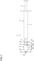
Figure 1] Fig. 1 is a plan view of an injection device according to a first arrangement. - [
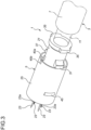
Figure 2] Fig. 2 is a perspective view of an injection needle as seen from the top end side according to the first arrangement. - [
Figure 3] Fig. 3 is a perspective view of the injection needle as seen from the base end side according to the first arrangement. - [
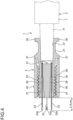
Figure 4] Fig. 4 is a sectional view as seen by IV-IV ofFig. 2 according to the first arrangement. - [
Figure 5] Fig. 5 is a perspective view of needles and a needle base of the injection needle as seen from the top end side according to the first arrangement. - [
Figure 6] Fig. 6 is a perspective view of the needles and the needle base of the injection needle as seen from the base end side according to the first arrangement. - [
Figure 7] Fig. 7 is a perspective view of an adjuster of the injection needle as seen from the top end side according to the first arrangement. - [
Figure 8] Fig. 8 is a perspective view of the adjuster of the injection needle as seen from the top end side according to the first arrangement. - [
Figure 9] Fig. 9 is a longitudinal sectional view of the injection needle in a state that the protrusion length of the needle is decreased by moving the adjuster forward according to the first arrangement. - [
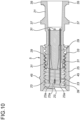
Figure 10] Fig. 10 is a longitudinal sectional view of the injection needle in a state that the needles are retracted in the adjuster by further moving the adjuster forward according to the first arrangement. - [
Figure 11] Fig. 11 is a perspective view of the injection needle in a state that the needles are covered by attaching a cap to the top end side according to the first arrangement. - [
Figure 12] Fig. 12 is a sectional view as seen by XII-XII ofFig. 11 according to the first arrangement. - [
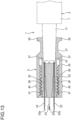
Figure 13] Fig. 13 is a longitudinal sectional view of an injection needle in a state that an adjuster moves rearward to the base end according to a second arrangement. The second arrangement is an embodiment of the present invention. - [
Figure 14] Fig. 14 is a longitudinal sectional view of the injection needle in a state that the adjuster moves forward to the top end according to the second arrangement. - [
Figure 15] Fig. 15 is a perspective view of the injection needle as seen from the top end side according to the second arrangement. - [
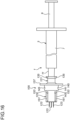
Figure 16] Fig. 16 is a plan view of an injection device according to a third arrangement. - [
Figure 17] Fig. 17 is a perspective view of an injection needle as seen from the top end side, in a state that an adjuster moves rearward to the base end according to the third arrangement. - [
Figure 18] Fig. 18 is a perspective view of the injection needle as seen from the base end side, in a state that the adjuster moves rearward to the base end according to the third arrangement. - [
Figure 19] Fig. 19 is a sectional view as seen by XIX-XIX ofFig. 17 according to the third arrangement. - [
Figure 20] Fig. 20 is a perspective view of the injection needle as seen from the top end side, in a state that the adjuster moves forward to the top end according to the third arrangement. - [
Figure 21] Fig. 21 is a perspective view of the injection needle as seen from the base end side, in a state that the adjuster moves forward to the top end according to the third arrangement. - [
Figure 22] Fig. 22 is a sectional view as seen by XXII-XXII ofFig. 20 according to the third arrangement. - [
Figure 23] Fig. 23 is a perspective view of the adjuster of the injection needle as seen from the top end side according to the third arrangement. - [
Figure 24] Fig. 24 is a perspective view of the adjuster of the injection needle as seen from the base end side according to the third arrangement. - [
Figure 25] Fig. 25 is a perspective view of a needle base of the injection needle as seen from the top end side according to the third arrangement. - [
Figure 26] Fig. 26 is a perspective view of the needle base of the injection needle as seen from the base end side according to the third arrangement. - [
Figure 27] Fig. 27 are views according to the third arrangement, in which,Fig. 27 (a) is a perspective view of a cap as seen from the top end side,Fig. 27 (b) is a perspective view of the cap as seen from the base end side, andFig. 27 (c) is a longitudinal sectional view of the injection needle with the cap. - [
Figure 28] Fig. 28 are views according to the third arrangement, in which,Fig. 28 (a) is perspective view of the injection needle with the cap as seen from the top end side,Fig. 28 (b) is a perspective view of the injection needle with the cap as seen from the base end side, andFig. 28 (c) is a longitudinal sectional view of the injection needle with the cap. - [
Figure 29] Fig. 29 are views according to a fourth arrangement, in which,Fig. 29 (a) is a perspective view of a cap,Fig. 29 (b) is a perspective view showing a state that a needle-base-side fitting part of the cap is fitted in the needle base. andFig. 29 (c) is a perspective view showing a state that the cap is turned reversely so that an adjuster-side fitting part of the cap is fitted in the adjuster. - Now, a first arrangement will be explained with reference to
Fig. 1 to Fig. 12 . As illustrated inFig. 1 , an injection device 1 according to the first arrangement is composed of asyringe 3, and aninjection needle 5 attached to be detachable to the top end of thesyringe 3. - The
syringe 3 is composed of aninjection cylinder 7 in a hollow shape, of which top end side (on the left ofFig. 1 ) and base end side (on the right ofFig. 1 ) are opening, and aplunger 9 inserted into theinjection cylinder 7 from the base end side (on the right ofFig. 1 ). The diameter at the top end side (on the left ofFig. 1 ) of theinjection cylinder 7 is reduced, serving as an injectionneedle connecting part 11. Theplunger 9 is disposed to be movable in the forward and rearward directions (in the left and right directions ofFig. 1 ) in the inside of theinjection cylinder 7. Theinjection cylinder 7 is filled with an unillustrated medicinal solution therein, and by moving theplunger 9 to the top end side (to the left ofFig. 1 ), the medicinal solution is discharged from the top end of theinjection cylinder 7. - As illustrated in
Fig. 1 to Fig. 4 , theinjection needle 5 is composed of aneedle base 21, and fourneedles Fig. 4 ) of theneedle base 21, and anadjuster 25. - As illustrated in
Fig. 4 , asyringe connecting recess 27 is formed on the base end side of theneedle base 21. The injectionneedle connecting part 11 of thesyringe 3 is inserted into thesyringe connecting recess 27. Moreover, as illustrated inFig. 2 ,Fig. 4 andFig. 5 , four needle fixing penetration holes 29, 29, 29, 29, each of which has openings both on the side of thesyringe connecting recess 27 and on the top end side (on the left ofFig. 4 ), are formed in theneedle base 21. Each of theneedles adhesives medicinal solution outlet 23a of each of theneedles needle base 21. - Moreover, as illustrated in
Fig. 4 ,Fig. 5 andFig. 6 , amale screw portion 33 is formed on the top end side (on the left ofFig. 4 ) of theneedle base 21. Moreover, as illustrated inFig. 5 andFig. 6 , the top and bottom ends of themale screw portion 33, as shown inFig. 5 , have been cut off due to molding reasons. These cut-off portions are shown byreference signs Fig. 4 ,Fig. 5 andFig. 6 , there areprojections Fig. 4 ) than the center of the axis direction (the left/right direction ofFig. 4 ) of theneedle base 21, there are base-end side stoppers - As illustrated in
Fig. 4 ,Fig. 7 and Fig. 8 , theadjuster 25 is a member in a cylindrical shape, and afemale thread portion 39 is formed in the inner peripheral surface thereof, to become in screw engagement with themale screw portion 33 of theneedle base 21. Theadjuster 25 is attached to theneedle base 21 to be movable along the axis direction, by the screw engagement structure between thefemale thread portion 39 and themale screw portion 33 of theneedle base 21. - With the rotative operation of the
adjuster 25 so as to move along the axis direction (the left/right direction ofFig. 4 ) of theneedle base 21, as illustrated inFig. 4 ,Fig. 9 andFig. 10 , the protrusion length of theneedles Fig. 4 ), respectively, and eventually the puncture depth of theneedles adjuster 25 is positioned at the right end ofFig. 4 so that the base end thereof becomes in contact with the base-end side stoppers needles - For reference, in the present arrangement, the maximum protrusion length (Lmax) of the
needle 23, as shown inFig. 4 , is set to 4 mm, as an example. - From the above state, when the
adjuster 25 is rotated counterclockwise as seen from the side facing to the direct front of theadjuster 25 at the left end inFig. 4 , so as to move to the left ofFig. 4 , theneedles adjuster 25, and the protrusion length (L) of each of theneedles - For reference, in the case of actual use, for the purpose of effective puncturing, the protrusion length (L) of each of the
needles - Moreover, after completion of puncture, as illustrated in
Fig. 10 , theadjuster 25 is moved to the top end side, until each of theneedles adjuster 25. Accordingly, it is possible to prevent accidental needle pricking caused by double-puncture (wrong puncture after completion of puncture) by users such as physicians or nurses. - For reference, in
Fig. 10 , the top end of each of theneedles adjuster 25, for example, at least about 1 to 3 mm inwardly. - Moreover, as illustrated in
Fig. 11 , there is a needle-base sidereference position marker 40a protrusively formed on theneedle base 21, and there is also an adjuster sidereference position marker 40b protrusively formed on theadjuster 25. The position in the rotative direction of the needle-base sidereference position marker 40a and the position in the rotative direction of the adjuster sidereference position marker 40b are set to match with each other, when theadjuster 25 is at the position closest to the base end side (a state as shown inFig. 4 ). - For example, when the
adjuster 25 moves from an initial state as described above, toward the top end side, by referring to the needle-base sidereference position marker 40a and also to the adjuster sidereference position marker 40b, it is possible to visually recognize how many times theadjuster 25 was rotated. By referring to such a number of rotations and to the leading amount of the screw engagement structure between themale screw portion 33 and thefemale thread portion 39, it is possible to set the protrusion amount of each of theneedles needles Fig. 4 has been determined (in the present arrangement, 4 mm), and meanwhile, with reference to the number of rotations of theadjuster 25, the moving amount of theadjuster 25 toward the top end side has also been determined. Thus, by deducting the moving amount (as shown by reference sign L' inFig. 9 ) from the maximum protrusion length in the initial state (Lmax), it is possible to set the protrusion length (L), and eventually the puncture depth, of each of theneedles - Moreover, as illustrated in
Fig. 11 andFig. 12 , before using, acap 41 is crowned to be detachable on the top end side (on the left ofFig. 12 ) of theadjuster 25 of theinjection needle 5. There areengagement openings cap 41, respectively, at positions opposing to each other at the angle of 180 degrees, and there are alsoengagement projections adjuster 25. By engagement of theengagement openings cap 41 with theengagement projections adjuster 25, respectively, thecap 41 is fixed in theadjuster 25. - For reference, as illustrated in
Fig. 12 , even in the initial state in which each of theneedles Fig. 12 ) of theadjuster 25, the top end of each of theneedles cap 41. - Next, the function according to the first arrangement will be explained.
- First, before using, the
injection needle 5 is in a state as shown inFig. 11 andFig. 12 . - Next, the medicinal solution is filled in the
injection cylinder 7 of thesyringe 3. - Next, the
injection needle 5 is attached to theinjection cylinder 7 of thesyringe 3. - Next, the
cap 41 is detached, so as to be in a usable state as illustrated inFig. 1 to Fig. 4 . In such a state, the protrusion length (L) of each of theneedles - Next, the
adjuster 25 is rotated counterclockwise as seen from the side facing to the direct front of theadjuster 25 at the left end inFig. 1 to Fig. 4 , so as to move theadjuster 25 to the left ofFig. 1 to Fig. 4 at an appropriate amount, whereby the protrusion length (L) of each of theneedles needles - Next, the side of the
needles needles Fig. 1 to Fig. 4 ) becomes in contact with the skin, and the puncture is performed at a predetermined puncture depth. - Next, the
plunger 9 of thesyringe 3 is depressed to apply force toward the top end side (the left ofFig. 1 to Fig. 4 ), whereby the medicinal solution is injected. - After completion of injection, the
needles adjuster 25 is rotated counterclockwise as seen from the side facing to the direct front of theadjuster 25 at the left end inFig. 1 to Fig. 4 , so as to move theadjuster 25 to the top end side (to the left ofFig. 1 to Fig. 4 ), and as illustrated inFig. 10 , the top end side of each of theneedles adjuster 25. Thus, the double-puncture (wrong puncture after completion of puncture) is prevented. Further, the top end is covered by crowning of thecap 41, and the whole body of the injection device 1 is disposed as the waste in such a state. Otherwise, only theinjection needle 5 is disposed as the waste, by detaching theinjection needle 5 from thesyringe 3. - Next, the effect according to the first arrangement will be explained.
- First, it is possible to arbitrarily adjust the protrusion length (L), and eventually the puncture depth of each of the
needles adjuster 25 is attached to be movable to the outer periphery of theneedle base 21, so that the position in the axis direction can be adjusted arbitrarily. - Moreover, since the protrusion length (L), and eventually the puncture depth of each of the
needles - Moreover, as illustrated in
Fig. 10 , after completion of puncture, the top end of each of theneedles adjuster 25, and accordingly, even without the need of attachment of thecap 41, it is possible to prevent accidental needle pricking caused by double-puncture (wrong puncture after completion of puncture) by users such as physicians or nurses. - Moreover, with the attachment of the
cap 41, the safety can be further improved. - Moreover, before using, the
cap 41 is crowned on the top end side of theadjuster 25, and accordingly, for example, it is possible to prevent injury of a user before using. - Moreover, since the
adjuster 25 is attached to be movable on the outer periphery of theneedle base 21 by the screw engagement structure, it is possible to move theadjuster 25 easily, and accordingly, the adjustment of the protrusion length (L), and eventually the puncture depth of each of theneedles - Moreover, the needle-base side
reference position marker 40a is formed on theneedle base 21, and the adjuster sidereference position marker 40b is also formed on theadjuster 25, and accordingly, it is possible to visually recognize the number of rotations of theadjuster 25, whereby the protrusion length (L), and eventually the puncture depth of each of theneedles - And moreover, since the
medicinal solution outlet 23a of each of theneedles needle base 21, the injected medicinal solution will diffuse widely, and simultaneously, will remain in a shallow portion of the skin. - Next, a second arrangement will be explained with reference to
Fig. 13 to Fig. 15 . In the first arrangement, the moving amount of theadjuster 25 toward the top end side is not limited specifically. However, in the second arrangement, this amount is limited to a predetermined value. - First, as illustrated in
Fig. 13 , an adjuster-side stopper 51 is provided on the base end side (on the left end side ofFig. 13 ) of theadjuster 25. The adjuster-side stopper 51 is in a ring shape, and is provided in a shape of collar. Meanwhile, the base end side (the right end side ofFig. 13 ) of thefemale thread portion 33, attached to theneedle base 21, serves as a needle-base-side stopper 53. Thus, with the movement of theadjuster 25 to the top end side (to the left ofFig. 13 ), and as illustrated inFig. 14 , when the adjuster-side stopper 51 becomes in contact with the needle-base-side stopper 53, the further movement of theadjuster 25 toward the top end side (the left ofFig. 14 ) is prohibited. Accordingly, theneedles adjuster 25, and also the drop-off of theadjuster 25 from theneedle base 21 is prevented. - Moreover, since the adjuster-
side stopper 51 is provided to theadjuster 25, there is a concern about the attachment of theadjuster 25 to theneedle base 21. To cope with this concern, as illustrated inFig. 15 , a longitudinally-split groove 55 is provided in theadjuster 25. When theadjuster 25 is attached to theneedle base 21, the attachment is performed by expanding the diameter of theadjuster 25, to some width within the range of the longitudinally-split groove 55. - The other structure is substantially the same as that of the first arrangement, and the same reference signs will be allotted to the same elements in the drawings, and the explain thereof will be omitted.
- According to the above structure, it is possible to achieve substantially the same effect as that of the first arrangement explained above.
- Moreover, since the moving amount of the
adjuster 25 to the top end side is limited to a predetermined value, it is possible to prevent any unintended drop-off of theadjuster 25 from theneedle base 21. - Moreover, when a user moves forward the
adjuster 25 until the adjuster-side stopper 51 becomes in contact with the needle-base-side stopper 53, the user is able to confirm that theneedles adjuster 25, at the position capable of preventing the double-puncture (wrong puncture after completion of puncture). - Next, a third arrangement will be explained with reference to
Fig. 16 to Fig. 28 . As illustrated inFig. 16 to Fig. 22 , aninjection needle 105 according to the third arrangement is composed of aneedle base 121, and fourneedles Fig. 16 of theneedle base 121, and anadjuster 125. - As illustrated in
Fig. 19 , asyringe connecting recess 127 is formed on the base end side of theneedle base 121. The injectionneedle connecting part 11 of thesyringe 3 is inserted into thesyringe connecting recess 127. Moreover, as illustrated inFig. 17 andFig. 19 , four needle fixing penetration holes 129, 129, 129, 129, each of which has openings both on the side of thesyringe connecting recess 127 and on the top end side (on the left ofFig. 25 ), are formed in theneedle base 121. - Each of the
needles adhesives Fig. 17 andFig. 19 , amedicinal solution outlet 123a of each of theneedles needle base 121. - Moreover, as illustrated in
Fig. 19 , amale screw portion 133 is formed on the top end side (on the left ofFig. 19 ) of theneedle base 121. Moreover, as illustrated inFig. 25 and Fig. 26 , the both transverse side portions of themale screw portion 133 have been cut off, serving as cut-offportions Fig. 19 ,Fig. 20 and Fig. 21 , there areprojections Fig. 19 ) than the center of the axis direction (the left/right direction ofFig. 19 ) of theneedle base 121, there is a substantially-diamond-shapedholding projection 137, formed protrusively in a shape of collar. The holdingprojection 137 also has a function to serve as a stopper to limit the rearward movement of theadjuster 125 to the base end side, to a predetermined amount. Moreover, as illustrated inFig. 20, Fig. 21 ,Fig. 25 and Fig. 26 , theneedle base 121 is provided with fourrecesses - As illustrated in
Fig. 17, Fig. 18 andFig. 19 , theadjuster 125 is composed of acollar portion 141, and acylindrical portion 143 fastened to thecollar portion 141. There areopenings collar portion 141, respectively, at positions opposing to each other at the angle of 180 degrees. Moreover, there areclaws cylindrical portion 143 on the side of thecollar portion 141. When thecylindrical portion 143 is inserted into the inner diametrical portion of thecollar portion 141, theclaws openings cylindrical portion 143 is integrated into thecollar portion 141. - Moreover, as illustrated in
Fig. 24 , an opening 142 of thecollar portion 141 is in a circular shape, of which two transverse side portions have been cut away, so as to formflat surfaces male screw portion 133 of theneedle base 121. When themale screw portion 133 of theneedle base 121 penetrates through the inside of theadjuster 125, the positions of the cut-offportions male screw portion 133 of theneedle base 121, and the positions of theflat surfaces collar portion 141 of theadjuster 125, shall be matched to each other. Moreover, after completion of attachment, when theadjuster 125 is rotated so as to move to the top end side, thecollar portion 141 becomes in contact with the end of themale screw portion 133, whereby the stopper function is exhibited, and further movement is prohibited. When the position of the cut-offportions male screw portion 133 of theneedle base 121, and the positions of theflat surfaces collar portion 141 of theadjuster 125, are matched to each other, the pulling off thereof can be performed, but the movement with the rotation cannot be performed. - There is a
female thread portion 149 formed in the inner peripheral surface of thecylindrical surface 143, to become in screw engagement with themale screw portion 133 of theneedle base 121. Theadjuster 125 is attached to theneedle base 121 to be movable along the axis direction, by the screw engagement structure between thefemale thread portion 149 and themale screw portion 133 of theneedle base 121. - As illustrated in
Fig. 16 to Fig. 18 ,Fig. 20 and Fig. 21 , there are rib-shapedguide projections 151 151, 151, 151, respectively, protrusively provided at four orthogonal positions on the outer peripheral surface of thecylindrical portion 143. Moreover, there areengagement projections guide projections collar portion 141. - Meanwhile, as illustrated in
Fig. 27 andFig. 28 , there is acap 155, and guideprojections cap 155, to be engaged with theguide projections cap 155 is crowned on theadjuster 125, theguide projections cap 155, are positioned, in a respective interval of theguide projections adjuster 125. Moreover, each of theguide projections cap 155 on theadjuster 125 can be performed smoothly. Moreover, there areengagement openings guide projections engagement openings respective engagement projections -
Fig. 28 shows a state, in which thecap 155 is crowned on theinjection needle 105. - The other structure is substantially the same as that of the first arrangement, and the same reference signs will be allotted to the same elements in the drawings, and the explain thereof will be omitted.
- Accordingly, it is possible to achieve substantially the same effect as that of the first arrangement described above.
- Moreover, since the holding
projection 137 is provided, for example, when theinjection needle 105 is attached to the top of thesyringe 3, the holdingprojection 137 is held by the left hand, and at the same time, thesyringe 3 is held by the right hand, whereby the injectionneedle connecting part 11 can be inserted into thesyringe connecting recess 127 so as to be attached thereto, and consequently, it is not necessary to hold thecap 155 or theadjuster 125, and there is no risk of unintended rotation of theadjuster 125 to fasten tightly. - Next, a fourth arrangement will be explained with reference to
Fig. 29 . In the case of the first to the third arrangements, the cap is fitted in the adjuster of the injection needle in a state that the rotation thereof is prohibited. On the other hand, in the case of the fourth arrangement, the cap is fitted in the needle base side in a state that the rotation thereof is prohibited. The details will be explained hereinafter. - As illustrated in
Fig. 29 (a) , acap 201 is provided with acap body 203, and a needle-base-sidefitting portion 205 is provided on one end side of thecap body 203, and furthermore, an adjuster-sidefitting portion 207 is provided on the other end side of thecap body 203. There areengagement portions fitting portion 205, at positions opposing to each other at the angle of 180 degrees. As illustrated inFig. 29 (b) , theengagement portions engagement portions projection 137 of theneedle base 121. - There are four
engagement opening engagement openings engagement projections 153 of the third arrangement), respectively, provided on theadjuster 125. - There are also four
engagement opening fitting portion 207. Theengagement openings adjuster 125. - The other structure is substantially the same as that of the third arrangement, and the same reference signs will be allotted to the same elements in the drawings, and the explain thereof will be omitted.
- According to the above structure, the normal state is shown in
Fig. 29 (b) , in which, the needle-base-sidefitting portion 205 of thecap 201, enclosing theadjuster 125 of the injection needle, has been fitted in a part of theneedle base 121, and also in which, theengagement portions fitting portion 205 are engaged with theengagement portions projection 137 of theneedle base 121. In this state, when theinjection needle 105 is attached to the top of the syringe, thecap 201 is held by the left hand, and at the same time, the syringe is held by the right hand, whereby the injection needle connecting part of the syringe is inserted into thesyringe connecting recess 127. At that time, since thecap 201 is fixed in the holdingprojection 137 and eventually in theneedle base 121, there is no risk of unintended rotation of thecap 201, and consequently, there is also no risk of unintended rotation of theadjuster 125. - Next, the adjustment of the protrusion length of the needle will be explained. For this purpose, as illustrated in
Fig. 29 (c) , the adjuster-sidefitting portion 207 of thecap 201 becomes engaged with theadjuster 125. In such a state, by holding thecap 201, theadjuster 125 is rotated, so as to adjust the protrusion length of the needle. Consequently, it is possible to prevent accidental needle pricking at the time of adjustment of the protrusion length of the needle. - The present invention is not limited to the first to the fourth arrangement as described above.
- First, in the first to the fourth arrangements, the explanations have been made for the structure of four needles as an example. However, it is of course possible to be composed of other structures, such as one needle, or two, three, five or more needles.
- Moreover, in the first to the fourth arrangements, the adjuster is movable by the screw engagement structure. However, the present invention is not limited to such a structure, and it is also possible, for example, to be movable by an appropriate fit-in-each-other structure.
- Moreover, in the second arrangement, it is possible to use the longitudinally-split groove also as the adjuster side reference position marker.
- Moreover, in the second arrangement, with the stopper mechanism, the needle is securely retracted by the adjuster, and the drop-off of the adjuster is prevented. However, it is also possible to utilize in the different structure, for the purpose of limiting the protrusion length of the needle within a predetermined range. As a possible structure, for example, in the initial state before using, the protrusion length of the needle may be set to 4 mm, and when the forward movement of the adjuster is prohibited by the stopper mechanism, the protrusion length of the needle may be set to 1 mm.
- Moreover, in the first to the fourth arrangements, the adjuster is rotated counterclockwise as seen from the side facing to the direct front of the adjuster, so as to shorten the protrusion length of the needle. However, it is also possible to rotate in the reverse direction.
- Moreover, in the first to the fourth arrangements, the adjuster is in the hollow cylindrical shape. However, the present invention is not limited to such a structure, and it is possible, for example, to be in a square shape, or any other shape. For example, in the case of square shape, if one rotation varies the length by 1 mm, then, the rotation at the angle of 90 degrees may vary the protrusion length by 1/4 mm.
- Moreover, in the first to the fourth arrangements, the adjuster is rotated in a state that the cap has been detached, so as to adjust the protrusion length of the needle. However, it is also possible to make such an adjustment in a state that the cap remains in the crowned state, whereby the accidental needle pricking can also be prevented.
- Moreover, it is also possible to provide scales of the protrusion length of the needle for reference purpose, on the adjuster or the needle base, by molding or printing.
- Moreover, in the first to the fourth arrangements, the medicinal solution outlet of the needle is oriented inwardly in the radial direction, but the direction is not limited to these arrangements.
- Moreover, in the fourth arrangement, the needle-base-side fitting portion and the adjuster-side fitting portion are provided in the opposite directions, respectively. However, it is also possible to provide the needle-base-side fitting portion only. In this structure, it is also possible that, by pulling the cap at a predetermined amount toward the top end side, the needle-base-side fitting portion is released from the fitting state in the needle base, and then, is fitted in the adjuster. Thus, in such a state, the protrusion length of the needle can also be adjusted by rotating the adjuster integrally with the cap.
- For example, in the fourth arrangement, in the state as illustrated in
Fig. 29 (b) , theengagement openings 213 is engaged with the engagement projection on the side of the adjuster. However, with regard to theengagement opening 213, by increasing the length in the axis direction thereof, even when the cap is pulled toward the top end side at a predetermined amount so as to release the fitting of the needle-base-side fitting portion out of the needle base, theengagement opening 213 may maintain the engagement state with the engagement projection on the side of the adjuster, and thus, in such a state, the protrusion length of the needle can be adjusted by rotating the adjuster integrally with the cap. - Moreover, as an another example, in the state as illustrated in
Fig. 29 (b) according to the fourth arrangement, it is also possible to provide a structure, in which, theengagement opening 213 passes by the engagement projection on the side of the adjuster without engagement therewith, and when the cap is pulled toward the top end side at a predetermined amount so as to release the fitting of the needle-base-side fitting portion out of the needle base, theengagement opening 213 becomes engaged with the engagement projection on the side of the adjuster. Thus, also in such a state, the protrusion length of the needle can be adjusted by rotating the adjuster integrally with the cap. - Furthermore, the structures shown in the drawings are merely for example purposes only.
- The present invention relates to the injection needle and the injection device for performing prevention and treatment of various diseases, for example by subcutaneous or intradermal administration of an objective substance, and more particularly, the present invention relates to the injection needle and the injection device, of which puncture depth of a needle can be adjusted. The present invention is suitable, for example, for the injection needle and the injection device used for treatment in the field of cosmetic dermatology.
-
- 1
- Injection Device
- 3
- Syringe
- 5
- Injection Needle
- 21
- Needle Base
- 23
- Needle
- 23a
- Medicinal Solution Outlet
- 25
- Adjuster
- 33
- Male Screw Portion
- 39
- Female Thread Portion
- 40a
- Needle-base Side Reference Position Marker
- 40b
- Adjuster Side Reference Position Marker
- 41
- Cap
- 51
- Adjuster-side Stopper
- 53
- Needle-base-side Stopper
- 55
- Longitudinally-split Groove
Claims (12)
- An injection needle provided with:a needle (23, 123);a needle base (21) holding the needle (23, 123) in a state of protruding toward the top end side; and an adjuster (25, 125) disposed to be movable along the axis direction of the needle base (21) on the outer periphery of the needle base (21), wherein a protrusion length of the needle (23, 123) is adjusted by adjusting a position of the adjuster (25, 125) in the axis direction;the adjuster (25, 125) is movable in the axis direction of the needle base (21) by a screw engagement structure;characterised in thatthe moving amount of the adjuster (25, 125) toward the top end side is limited to a predetermined amount by a stopper mechanism (51, 53);the stopper mechanism (51, 53) is composed of a collar portion (51) on the side of the adjuster (25, 125) becoming in contact with an end of a male screw portion (33) on the side of the needle base (21).
- The injection needle as claimed in Claim 1, wherein, the top end of the needle (23, 123) is capable of being retracted in the adjuster (25, 125).
- The injection needle as claimed in Claim 1, wherein, a needle base (21) is provided with a needle-base side reference position marker (40a), and the adjuster (25, 125) is provided with an adjuster side reference position marker (40b).
- The injection needle as claimed in Claim 1, wherein,
the adjuster (25, 125) is provided with a longitudinally-split groove (55), so as to allow expansion of the diameter when attaching to the needle base (21). - The injection needle as claimed in Claim 1, wherein, the cross-section shape of the male screw portion (33) of the needle base (21) is in a non-circular shape, and the cross-section shape of an opening of the collar portion (51) of the adjuster is also in a non-circular shape correspondingly, and by matching each position in the rotative direction, the male screw portion (33) becomes capable of penetrating through the inside of the adjuster (25, 125).
- The injection needle as claimed in any one Claim among Claim 1 to Claim 5, wherein, the needle (23, 123) is provided in a plural number.
- The injection needle as claimed in Claim 6, wherein, a medicinal solution outlet (23, 123a) of the needle (23, 123) is oriented inwardly in the radial direction of the needle base (21).
- The injection needle as claimed in any one Claim among Claim 1 to Claim 7, wherein, the needle base (21) is provided with a holding projection.
- The injection needle as claimed in any one Claim among Claim 1 to Claim 8, wherein, the outer periphery of the adjuster (25, 125) is crowned with a cap (41, 201) so as to cover the needle.
- The injection needle as claimed in Claim 9, wherein,
the cap (41) is fitted in the adjuster, so that the adjuster (25, 125) is capable of being rotated with the rotation of the cap (41). - The injection needle as claimed in Claim 10, wherein,
the adjuster (25, 125) is provided with an engagement projection (45), and the cap (41) is provided with an engagement opening to be engaged with the engagement projection (45). - The injection needle as claimed in Claim 9, wherein, the cap encloses the adjuster and is fitted in the needle base in a state that the rotation is prohibited.
Applications Claiming Priority (2)
| Application Number | Priority Date | Filing Date | Title |
|---|---|---|---|
| JP2018081378 | 2018-04-20 | ||
| PCT/JP2019/016607 WO2019203298A1 (en) | 2018-04-20 | 2019-04-18 | Injection needle and injection device |
Publications (3)
| Publication Number | Publication Date |
|---|---|
| EP3782679A1 EP3782679A1 (en) | 2021-02-24 |
| EP3782679A4 EP3782679A4 (en) | 2021-12-22 |
| EP3782679B1 true EP3782679B1 (en) | 2025-07-02 |
Family
ID=68240135
Family Applications (1)
| Application Number | Title | Priority Date | Filing Date |
|---|---|---|---|
| EP19787708.7A Active EP3782679B1 (en) | 2018-04-20 | 2019-04-18 | Injection needle and injection device |
Country Status (5)
| Country | Link |
|---|---|
| US (1) | US20210178087A1 (en) |
| EP (1) | EP3782679B1 (en) |
| JP (1) | JP7282750B2 (en) |
| KR (1) | KR102700037B1 (en) |
| WO (1) | WO2019203298A1 (en) |
Families Citing this family (4)
| Publication number | Priority date | Publication date | Assignee | Title |
|---|---|---|---|---|
| KR102475864B1 (en) * | 2020-03-25 | 2022-12-09 | 진세훈 | Syringe for selective self dermal rejuvenation |
| CN112755338B (en) * | 2021-02-04 | 2025-09-05 | 艾美创医疗科技(珠海)有限公司 | A precisely calibrated boss-type multi-needle injection needle |
| IT202100020528A1 (en) * | 2021-07-30 | 2023-01-30 | Fiderm Srl | Device for adjusting the penetration depth of a syringe needle and syringe including said device |
| CN114082042B (en) * | 2021-10-19 | 2022-08-19 | 苏州和林微纳科技股份有限公司 | Unified injection depth telescopic type insulin syringe |
Family Cites Families (12)
| Publication number | Priority date | Publication date | Assignee | Title |
|---|---|---|---|---|
| KR101106495B1 (en) * | 2009-01-14 | 2012-01-20 | 방시열 | Needle Assembly Tube Assembly |
| KR101129053B1 (en) * | 2009-07-16 | 2012-03-23 | 주식회사 필텍 | Safety syringe for adjusting length of needle |
| KR101129054B1 (en) * | 2009-07-16 | 2012-03-23 | 주식회사 필텍 | Safety syringe for adjusting length of needle |
| KR20120020216A (en) * | 2010-08-27 | 2012-03-08 | (주)우리메카 | Multi injection needle for controlling injection depth |
| KR20120044612A (en) * | 2010-10-28 | 2012-05-08 | (주)엠툴즈 | Module for skin resurfacing |
| US8491535B2 (en) * | 2011-04-28 | 2013-07-23 | Becton, Dickinson And Company | Safety pen needle assembly |
| JP5890430B2 (en) | 2011-11-02 | 2016-03-22 | 南部化成株式会社 | Transdermal dosing device and chemical injection needle used in the device |
| JP6037722B2 (en) * | 2012-08-27 | 2016-12-07 | 南部化成株式会社 | Needle |
| US9937299B2 (en) * | 2013-09-26 | 2018-04-10 | Becton, Dickinson And Company | Adjustable penetration depth syringe |
| KR101713938B1 (en) * | 2015-05-18 | 2017-03-08 | 김광현 | Needle unit for medication injection device |
| US10220195B2 (en) * | 2016-06-08 | 2019-03-05 | Eclipse Medcorp, Llc | Radio frequency needling device for use with disposable needle cartridges |
| US10328214B2 (en) | 2016-09-30 | 2019-06-25 | William Carson | Syringe guide and method for its use |
-
2019
- 2019-04-18 US US17/046,530 patent/US20210178087A1/en not_active Abandoned
- 2019-04-18 EP EP19787708.7A patent/EP3782679B1/en active Active
- 2019-04-18 KR KR1020207031254A patent/KR102700037B1/en active Active
- 2019-04-18 WO PCT/JP2019/016607 patent/WO2019203298A1/en not_active Ceased
- 2019-04-18 JP JP2020514433A patent/JP7282750B2/en active Active
Also Published As
| Publication number | Publication date |
|---|---|
| JP7282750B2 (en) | 2023-05-29 |
| EP3782679A4 (en) | 2021-12-22 |
| KR102700037B1 (en) | 2024-08-27 |
| US20210178087A1 (en) | 2021-06-17 |
| WO2019203298A1 (en) | 2019-10-24 |
| EP3782679A1 (en) | 2021-02-24 |
| JPWO2019203298A1 (en) | 2021-04-22 |
| KR20210002508A (en) | 2021-01-08 |
Similar Documents
| Publication | Publication Date | Title |
|---|---|---|
| EP3782679A1 (en) | Injection needle and injection device | |
| CN107635610B (en) | Safety device for syringe | |
| US8062265B2 (en) | Automatic needle guard for medication pen | |
| AU2004286735B2 (en) | Autoinjection device | |
| US10086152B2 (en) | Liquid administration device | |
| RU2728936C2 (en) | Syringe for implant | |
| JP4493126B2 (en) | Endoscopic needle | |
| JP2018521716A (en) | Safety device for prefilled syringes | |
| KR101439228B1 (en) | Precision filler injection apparatus for preventing side effect and pain | |
| JP2018518252A (en) | Safety device for syringe | |
| WO2014115241A1 (en) | Liquid dispenser | |
| JP2018520805A (en) | Liquid product automatic injection device including injection spring | |
| CN113272002B (en) | Equipment for placing components using sleeves | |
| US5421347A (en) | Disposable lancet device for puncturing skin | |
| EP2990066B1 (en) | Syringe | |
| US5947936A (en) | Syringe with spring biased needle cover | |
| US7377911B2 (en) | Medical needle device with winged shield for erroneous piercing prevention | |
| EP3369447A1 (en) | Grip and syringe assembly | |
| CA3030336C (en) | Medicament container holder for a medicament delivery device and method of assemblying a medicament delivery device | |
| EP3500323B1 (en) | Safety needle with deformable cannula for injector pen | |
| EP3097935B1 (en) | Winged injection needle | |
| KR100581037B1 (en) | Medical needle device with shield to prevent five stars | |
| US20170056601A1 (en) | Needle assembly | |
| WO2008118170A1 (en) | Automatic needle guard for medication pen | |
| WO2018101482A1 (en) | Needle assembly and needle device having same |
Legal Events
| Date | Code | Title | Description |
|---|---|---|---|
| STAA | Information on the status of an ep patent application or granted ep patent |
Free format text: STATUS: THE INTERNATIONAL PUBLICATION HAS BEEN MADE |
|
| PUAI | Public reference made under article 153(3) epc to a published international application that has entered the european phase |
Free format text: ORIGINAL CODE: 0009012 |
|
| STAA | Information on the status of an ep patent application or granted ep patent |
Free format text: STATUS: REQUEST FOR EXAMINATION WAS MADE |
|
| 17P | Request for examination filed |
Effective date: 20201104 |
|
| AK | Designated contracting states |
Kind code of ref document: A1 Designated state(s): AL AT BE BG CH CY CZ DE DK EE ES FI FR GB GR HR HU IE IS IT LI LT LU LV MC MK MT NL NO PL PT RO RS SE SI SK SM TR |
|
| AX | Request for extension of the european patent |
Extension state: BA ME |
|
| DAV | Request for validation of the european patent (deleted) | ||
| DAX | Request for extension of the european patent (deleted) | ||
| A4 | Supplementary search report drawn up and despatched |
Effective date: 20211123 |
|
| RIC1 | Information provided on ipc code assigned before grant |
Ipc: A61M 5/32 20060101ALI20211117BHEP Ipc: A61M 5/28 20060101ALI20211117BHEP Ipc: A61M 5/46 20060101AFI20211117BHEP |
|
| GRAP | Despatch of communication of intention to grant a patent |
Free format text: ORIGINAL CODE: EPIDOSNIGR1 |
|
| STAA | Information on the status of an ep patent application or granted ep patent |
Free format text: STATUS: GRANT OF PATENT IS INTENDED |
|
| INTG | Intention to grant announced |
Effective date: 20250220 |
|
| GRAS | Grant fee paid |
Free format text: ORIGINAL CODE: EPIDOSNIGR3 |
|
| GRAA | (expected) grant |
Free format text: ORIGINAL CODE: 0009210 |
|
| STAA | Information on the status of an ep patent application or granted ep patent |
Free format text: STATUS: THE PATENT HAS BEEN GRANTED |
|
| AK | Designated contracting states |
Kind code of ref document: B1 Designated state(s): AL AT BE BG CH CY CZ DE DK EE ES FI FR GB GR HR HU IE IS IT LI LT LU LV MC MK MT NL NO PL PT RO RS SE SI SK SM TR |
|
| REG | Reference to a national code |
Ref country code: GB Ref legal event code: FG4D |
|
| REG | Reference to a national code |
Ref country code: CH Ref legal event code: EP |
|
| REG | Reference to a national code |
Ref country code: DE Ref legal event code: R096 Ref document number: 602019071976 Country of ref document: DE |
|
| REG | Reference to a national code |
Ref country code: IE Ref legal event code: FG4D |
|
| REG | Reference to a national code |
Ref country code: NL Ref legal event code: MP Effective date: 20250702 |
|
| PG25 | Lapsed in a contracting state [announced via postgrant information from national office to epo] |
Ref country code: PT Free format text: LAPSE BECAUSE OF FAILURE TO SUBMIT A TRANSLATION OF THE DESCRIPTION OR TO PAY THE FEE WITHIN THE PRESCRIBED TIME-LIMIT Effective date: 20251103 |
|
| PG25 | Lapsed in a contracting state [announced via postgrant information from national office to epo] |
Ref country code: NL Free format text: LAPSE BECAUSE OF FAILURE TO SUBMIT A TRANSLATION OF THE DESCRIPTION OR TO PAY THE FEE WITHIN THE PRESCRIBED TIME-LIMIT Effective date: 20250702 |
|
| REG | Reference to a national code |
Ref country code: AT Ref legal event code: MK05 Ref document number: 1808560 Country of ref document: AT Kind code of ref document: T Effective date: 20250702 |
|
| PG25 | Lapsed in a contracting state [announced via postgrant information from national office to epo] |
Ref country code: IS Free format text: LAPSE BECAUSE OF FAILURE TO SUBMIT A TRANSLATION OF THE DESCRIPTION OR TO PAY THE FEE WITHIN THE PRESCRIBED TIME-LIMIT Effective date: 20251102 |
|
| PG25 | Lapsed in a contracting state [announced via postgrant information from national office to epo] |
Ref country code: NO Free format text: LAPSE BECAUSE OF FAILURE TO SUBMIT A TRANSLATION OF THE DESCRIPTION OR TO PAY THE FEE WITHIN THE PRESCRIBED TIME-LIMIT Effective date: 20251002 |
|
| REG | Reference to a national code |
Ref country code: LT Ref legal event code: MG9D |
|
| PG25 | Lapsed in a contracting state [announced via postgrant information from national office to epo] |
Ref country code: AT Free format text: LAPSE BECAUSE OF FAILURE TO SUBMIT A TRANSLATION OF THE DESCRIPTION OR TO PAY THE FEE WITHIN THE PRESCRIBED TIME-LIMIT Effective date: 20250702 |
|
| PG25 | Lapsed in a contracting state [announced via postgrant information from national office to epo] |
Ref country code: FI Free format text: LAPSE BECAUSE OF FAILURE TO SUBMIT A TRANSLATION OF THE DESCRIPTION OR TO PAY THE FEE WITHIN THE PRESCRIBED TIME-LIMIT Effective date: 20250702 |
|
| PG25 | Lapsed in a contracting state [announced via postgrant information from national office to epo] |
Ref country code: HR Free format text: LAPSE BECAUSE OF FAILURE TO SUBMIT A TRANSLATION OF THE DESCRIPTION OR TO PAY THE FEE WITHIN THE PRESCRIBED TIME-LIMIT Effective date: 20250702 |
|
| PG25 | Lapsed in a contracting state [announced via postgrant information from national office to epo] |
Ref country code: GR Free format text: LAPSE BECAUSE OF FAILURE TO SUBMIT A TRANSLATION OF THE DESCRIPTION OR TO PAY THE FEE WITHIN THE PRESCRIBED TIME-LIMIT Effective date: 20251003 |
|
| PG25 | Lapsed in a contracting state [announced via postgrant information from national office to epo] |
Ref country code: SE Free format text: LAPSE BECAUSE OF FAILURE TO SUBMIT A TRANSLATION OF THE DESCRIPTION OR TO PAY THE FEE WITHIN THE PRESCRIBED TIME-LIMIT Effective date: 20250702 Ref country code: CZ Free format text: LAPSE BECAUSE OF FAILURE TO SUBMIT A TRANSLATION OF THE DESCRIPTION OR TO PAY THE FEE WITHIN THE PRESCRIBED TIME-LIMIT Effective date: 20250702 |
|
| PG25 | Lapsed in a contracting state [announced via postgrant information from national office to epo] |
Ref country code: LV Free format text: LAPSE BECAUSE OF FAILURE TO SUBMIT A TRANSLATION OF THE DESCRIPTION OR TO PAY THE FEE WITHIN THE PRESCRIBED TIME-LIMIT Effective date: 20250702 |
|
| PG25 | Lapsed in a contracting state [announced via postgrant information from national office to epo] |
Ref country code: BG Free format text: LAPSE BECAUSE OF FAILURE TO SUBMIT A TRANSLATION OF THE DESCRIPTION OR TO PAY THE FEE WITHIN THE PRESCRIBED TIME-LIMIT Effective date: 20250702 Ref country code: PL Free format text: LAPSE BECAUSE OF FAILURE TO SUBMIT A TRANSLATION OF THE DESCRIPTION OR TO PAY THE FEE WITHIN THE PRESCRIBED TIME-LIMIT Effective date: 20250702 |
|
| PG25 | Lapsed in a contracting state [announced via postgrant information from national office to epo] |
Ref country code: RS Free format text: LAPSE BECAUSE OF FAILURE TO SUBMIT A TRANSLATION OF THE DESCRIPTION OR TO PAY THE FEE WITHIN THE PRESCRIBED TIME-LIMIT Effective date: 20251002 |
|
| PG25 | Lapsed in a contracting state [announced via postgrant information from national office to epo] |
Ref country code: ES Free format text: LAPSE BECAUSE OF FAILURE TO SUBMIT A TRANSLATION OF THE DESCRIPTION OR TO PAY THE FEE WITHIN THE PRESCRIBED TIME-LIMIT Effective date: 20250702 |
|
| PG25 | Lapsed in a contracting state [announced via postgrant information from national office to epo] |
Ref country code: SM Free format text: LAPSE BECAUSE OF FAILURE TO SUBMIT A TRANSLATION OF THE DESCRIPTION OR TO PAY THE FEE WITHIN THE PRESCRIBED TIME-LIMIT Effective date: 20250702 |
|
| REG | Reference to a national code |
Ref country code: DE Ref legal event code: R097 Ref document number: 602019071976 Country of ref document: DE |
|
| PG25 | Lapsed in a contracting state [announced via postgrant information from national office to epo] |
Ref country code: DK Free format text: LAPSE BECAUSE OF FAILURE TO SUBMIT A TRANSLATION OF THE DESCRIPTION OR TO PAY THE FEE WITHIN THE PRESCRIBED TIME-LIMIT Effective date: 20250702 |
|
| PG25 | Lapsed in a contracting state [announced via postgrant information from national office to epo] |
Ref country code: IT Free format text: LAPSE BECAUSE OF FAILURE TO SUBMIT A TRANSLATION OF THE DESCRIPTION OR TO PAY THE FEE WITHIN THE PRESCRIBED TIME-LIMIT Effective date: 20250702 |
|
| PG25 | Lapsed in a contracting state [announced via postgrant information from national office to epo] |
Ref country code: SK Free format text: LAPSE BECAUSE OF FAILURE TO SUBMIT A TRANSLATION OF THE DESCRIPTION OR TO PAY THE FEE WITHIN THE PRESCRIBED TIME-LIMIT Effective date: 20250702 Ref country code: EE Free format text: LAPSE BECAUSE OF FAILURE TO SUBMIT A TRANSLATION OF THE DESCRIPTION OR TO PAY THE FEE WITHIN THE PRESCRIBED TIME-LIMIT Effective date: 20250702 |
|
| PLBE | No opposition filed within time limit |
Free format text: ORIGINAL CODE: 0009261 |
|
| STAA | Information on the status of an ep patent application or granted ep patent |
Free format text: STATUS: NO OPPOSITION FILED WITHIN TIME LIMIT |
|
| REG | Reference to a national code |
Ref country code: CH Ref legal event code: L10 Free format text: ST27 STATUS EVENT CODE: U-0-0-L10-L00 (AS PROVIDED BY THE NATIONAL OFFICE) Effective date: 20260518 |
|
| 26N | No opposition filed |
Effective date: 20260407 |
|
| PG25 | Lapsed in a contracting state [announced via postgrant information from national office to epo] |
Ref country code: LT Free format text: LAPSE BECAUSE OF FAILURE TO SUBMIT A TRANSLATION OF THE DESCRIPTION OR TO PAY THE FEE WITHIN THE PRESCRIBED TIME-LIMIT Effective date: 20250702 |
|
| PGFP | Annual fee paid to national office [announced via postgrant information from national office to epo] |
Ref country code: DE Payment date: 20260427 Year of fee payment: 8 |