EP3782588A1 - Sole for sports artificial foot - Google Patents
Sole for sports artificial foot Download PDFInfo
- Publication number
- EP3782588A1 EP3782588A1 EP19787984.4A EP19787984A EP3782588A1 EP 3782588 A1 EP3782588 A1 EP 3782588A1 EP 19787984 A EP19787984 A EP 19787984A EP 3782588 A1 EP3782588 A1 EP 3782588A1
- Authority
- EP
- European Patent Office
- Prior art keywords
- region
- sole
- curved portion
- leg
- prosthetic leg
- Prior art date
- Legal status (The legal status is an assumption and is not a legal conclusion. Google has not performed a legal analysis and makes no representation as to the accuracy of the status listed.)
- Granted
Links
Images





Classifications
-
- A—HUMAN NECESSITIES
- A61—MEDICAL OR VETERINARY SCIENCE; HYGIENE
- A61F—FILTERS IMPLANTABLE INTO BLOOD VESSELS; PROSTHESES; DEVICES PROVIDING PATENCY TO, OR PREVENTING COLLAPSING OF, TUBULAR STRUCTURES OF THE BODY, e.g. STENTS; ORTHOPAEDIC, NURSING OR CONTRACEPTIVE DEVICES; FOMENTATION; TREATMENT OR PROTECTION OF EYES OR EARS; BANDAGES, DRESSINGS OR ABSORBENT PADS; FIRST-AID KITS
- A61F2/00—Filters implantable into blood vessels; Prostheses, i.e. artificial substitutes or replacements for parts of the body; Appliances for connecting them with the body; Devices providing patency to, or preventing collapsing of, tubular structures of the body, e.g. stents
- A61F2/50—Prostheses not implantable in the body
- A61F2/60—Artificial legs or feet or parts thereof
- A61F2/66—Feet; Ankle joints
-
- A—HUMAN NECESSITIES
- A61—MEDICAL OR VETERINARY SCIENCE; HYGIENE
- A61F—FILTERS IMPLANTABLE INTO BLOOD VESSELS; PROSTHESES; DEVICES PROVIDING PATENCY TO, OR PREVENTING COLLAPSING OF, TUBULAR STRUCTURES OF THE BODY, e.g. STENTS; ORTHOPAEDIC, NURSING OR CONTRACEPTIVE DEVICES; FOMENTATION; TREATMENT OR PROTECTION OF EYES OR EARS; BANDAGES, DRESSINGS OR ABSORBENT PADS; FIRST-AID KITS
- A61F2/00—Filters implantable into blood vessels; Prostheses, i.e. artificial substitutes or replacements for parts of the body; Appliances for connecting them with the body; Devices providing patency to, or preventing collapsing of, tubular structures of the body, e.g. stents
- A61F2/50—Prostheses not implantable in the body
- A61F2/60—Artificial legs or feet or parts thereof
-
- A—HUMAN NECESSITIES
- A61—MEDICAL OR VETERINARY SCIENCE; HYGIENE
- A61F—FILTERS IMPLANTABLE INTO BLOOD VESSELS; PROSTHESES; DEVICES PROVIDING PATENCY TO, OR PREVENTING COLLAPSING OF, TUBULAR STRUCTURES OF THE BODY, e.g. STENTS; ORTHOPAEDIC, NURSING OR CONTRACEPTIVE DEVICES; FOMENTATION; TREATMENT OR PROTECTION OF EYES OR EARS; BANDAGES, DRESSINGS OR ABSORBENT PADS; FIRST-AID KITS
- A61F2/00—Filters implantable into blood vessels; Prostheses, i.e. artificial substitutes or replacements for parts of the body; Appliances for connecting them with the body; Devices providing patency to, or preventing collapsing of, tubular structures of the body, e.g. stents
- A61F2/50—Prostheses not implantable in the body
- A61F2002/5072—Prostheses not implantable in the body having spring elements
- A61F2002/5079—Leaf springs
-
- A—HUMAN NECESSITIES
- A61—MEDICAL OR VETERINARY SCIENCE; HYGIENE
- A61F—FILTERS IMPLANTABLE INTO BLOOD VESSELS; PROSTHESES; DEVICES PROVIDING PATENCY TO, OR PREVENTING COLLAPSING OF, TUBULAR STRUCTURES OF THE BODY, e.g. STENTS; ORTHOPAEDIC, NURSING OR CONTRACEPTIVE DEVICES; FOMENTATION; TREATMENT OR PROTECTION OF EYES OR EARS; BANDAGES, DRESSINGS OR ABSORBENT PADS; FIRST-AID KITS
- A61F2/00—Filters implantable into blood vessels; Prostheses, i.e. artificial substitutes or replacements for parts of the body; Appliances for connecting them with the body; Devices providing patency to, or preventing collapsing of, tubular structures of the body, e.g. stents
- A61F2/50—Prostheses not implantable in the body
- A61F2/60—Artificial legs or feet or parts thereof
- A61F2002/607—Lower legs
-
- A—HUMAN NECESSITIES
- A61—MEDICAL OR VETERINARY SCIENCE; HYGIENE
- A61F—FILTERS IMPLANTABLE INTO BLOOD VESSELS; PROSTHESES; DEVICES PROVIDING PATENCY TO, OR PREVENTING COLLAPSING OF, TUBULAR STRUCTURES OF THE BODY, e.g. STENTS; ORTHOPAEDIC, NURSING OR CONTRACEPTIVE DEVICES; FOMENTATION; TREATMENT OR PROTECTION OF EYES OR EARS; BANDAGES, DRESSINGS OR ABSORBENT PADS; FIRST-AID KITS
- A61F2/00—Filters implantable into blood vessels; Prostheses, i.e. artificial substitutes or replacements for parts of the body; Appliances for connecting them with the body; Devices providing patency to, or preventing collapsing of, tubular structures of the body, e.g. stents
- A61F2/50—Prostheses not implantable in the body
- A61F2/60—Artificial legs or feet or parts thereof
- A61F2/66—Feet; Ankle joints
- A61F2002/6614—Feet
- A61F2002/665—Soles
-
- A—HUMAN NECESSITIES
- A61—MEDICAL OR VETERINARY SCIENCE; HYGIENE
- A61F—FILTERS IMPLANTABLE INTO BLOOD VESSELS; PROSTHESES; DEVICES PROVIDING PATENCY TO, OR PREVENTING COLLAPSING OF, TUBULAR STRUCTURES OF THE BODY, e.g. STENTS; ORTHOPAEDIC, NURSING OR CONTRACEPTIVE DEVICES; FOMENTATION; TREATMENT OR PROTECTION OF EYES OR EARS; BANDAGES, DRESSINGS OR ABSORBENT PADS; FIRST-AID KITS
- A61F2/00—Filters implantable into blood vessels; Prostheses, i.e. artificial substitutes or replacements for parts of the body; Appliances for connecting them with the body; Devices providing patency to, or preventing collapsing of, tubular structures of the body, e.g. stents
- A61F2/50—Prostheses not implantable in the body
- A61F2/60—Artificial legs or feet or parts thereof
- A61F2/66—Feet; Ankle joints
- A61F2002/6614—Feet
- A61F2002/6657—Feet having a plate-like or strip-like spring element, e.g. an energy-storing cantilever spring keel
- A61F2002/6678—L-shaped
Definitions
- the present disclosure relates to a sole attached to a ground contact region of an athletic prosthetic leg, in particular, to a sole of an athletic prosthetic leg which inhibits slip of the prosthetic leg during a competition.
- a prosthetic leg for a competition (hereinafter, referred to as an athletic prosthetic leg or simply referred to as a prosthetic leg) having a leaf-spring-like leg portion which extends via a curved portion to a side of a toe and in which a ground contact region extends from the toe to a side of the curved portion in an arc has been well-known.
- an athletic prosthetic leg having the leaf-spring-like leg portion generally, a sole which abuts a road surface is attached to a bottom surface of the ground contact region.
- Patent Literature 1 illustrates a sole which is attached to a lower surface of a curved leaf-spring-like athletic prosthetic leg to correspond to sporting events such as jogging or running.
- Patent Literature 1 discloses a sole to which a spike is attached at a lower surface of the sole contacting a road surface or a sole provided with a number of outsole portions each having a hexagonal contact patch.
- An object of the present disclosure is to provide a sole of an athletic prosthetic leg having a high anti-slip property.
- the inventor earnestly studied means to solve the problem.
- a ground contact form of an athletic prosthetic leg has been reviewed in detail
- the inventor newly found that the athletic prosthetic leg illustrates a unique ground contact form caused by the shape of a leaf-spring-like leg portion.
- a high anti-slip property can be achieved by allowing a bottom surface of a sole to correspond to a ground contact form which is unique to the athletic prosthetic leg to separate functions of the sole, and completed the present disclosure.
- a sole of an athletic prosthetic leg having a leaf-spring-like leg portion extending to a side of a toe via at least one curved portion, the sole being configured to be attached to a ground contact region of the athletic prosthetic leg, the ground contact region extending from the toe to a side of the curved portion in an arc
- the sole includes a bottom surface having a shape conforming to an extending shape of the ground contact region, and, in the bottom surface, a region at the side of the curved portion has a higher drainage performance compared with a region other than the region at the side of the curved portion, the region at the side of the curved portion being defined by a border as a line extending in a width direction of the leg portion through a contact point with a road surface in a standing state of a wearer who wears the athletic prosthetic leg.
- a sole of an athletic prosthetic leg having a high anti-slip property can be provided. Attachment of this sole to the athletic prosthetic leg provides an effect of fully exerting an athlete's skill.
- a sole of an athletic prosthetic leg of the present disclosure (hereinafter, it is also referred to as a sole) will be explained in detail with illustration of embodiments thereof.
- FIG. 1 is a side view of an athletic prosthetic leg 1 to which a sole 5 according to a first embodiment of the present disclosure is attached.
- the athletic prosthetic leg 1 has a leaf-spring-like leg portion 2, and the sole 5 is attached to a ground contact region at its tip side. Additionally, while illustration is omitted, a base end portion of the leg portion 2 is connected to a socket via an adapter and the socket houses a stump of a wearer's leg, whereby the wearer can wear the prosthetic leg.
- the adapter and the socket which correspond to the position of the stump of the leg, such as an above-knee prosthesis and a below-knee prosthesis, are used.
- FIG. 1 illustrates the leg portion 2 and the sole 5 in a standing state of the wearer who wears the athletic prosthetic leg 1.
- a side where the leg portion 2 is connected to the adapter is referred to as a connection side
- a side where the leg portion 2 contacts a road surface S is referred to as a ground contact side
- a toe T of the athletic prosthetic leg 1 refers to a point at the forefront as a termination of the leg portion 2 extending from the connection side.
- a direction extending from the toe T in parallel with the road surface S is referred to as a leg portion front-rear direction Y.
- a widthwise direction of the leg portion 2 is referred to as a width direction W.
- the leg portion 2 of the athletic prosthetic leg 1 has a plate-like extending shape to the side of the toe T via at least one curved portion, in the illustrated example, one curved portion 3.
- the leg portion 2 is constituted by, in the order from the connecting side to the ground contact side, a straight portion 2a, a curved portion 2b which is convex to the side of the toe T, the curved portion 3 which is convex to a rear side in the leg portion front-rear direction Y, a curved portion 2c which is concave to the ground contact side and a ground contact portion 4 which is convex to the ground contact side to extend to the side of the toe T in an arc.
- leg portion 2 is not limited, from a viewpoint of strength and weight saving, fiber reinforced plastic etc. is preferably used.
- the ground contact portion 4 includes a ground contact region 4s extending from the toe T to the side of the curved portion 3 in an arc at the ground contact side, and the sole 5 is attached to the ground contact region 4s.
- the ground contact region 4s refers to the entire region abutting the road surface S when the wearer who wears the athletic prosthetic leg 1 executes straight running movement, and in a state that sole 5 is attached, the ground contact region 4s abuts the road surface S via the sole 5.
- the sole 5 has a shape conforming to an extending shape of the ground contact region 4s. Also, the ground contact side of the sole 5 is a bottom surface 5s. As illustrated in FIG. 1 , the bottom surface 5s has a shape in which an arc X1 and an arc X2 are continued from the toe T side to the curved portion 3 side. While the arc X1 and the arc X2 have a different radius of curvature to each other in this embodiment, they may include the same radius of curvature.
- the bottom surface 5s has different properties at one side and the other side, which are defined by a border as a line extending in the width direction W through a point C as a contact point with the road surface S in a standing state of the wearer when the athletic prosthetic leg 1 is worn.
- the point C is a point which firstly contacts the road surface S in arriving at standing.
- the standing state refers to a state that the wearer firstly contacts the road surface S by lowering the athletic prosthetic leg 1 to the road surface S from a state that the wearer supports his body by a healthy leg wearing no prosthetic leg when a prosthetic leg is used for only one leg, or the wearer supports his body by one prosthetic leg when prosthetic legs are used for both legs.
- the point C is determined depending on the shape or an attachment aspect etc. of the prosthetic leg.
- the inventor newly conceived that the border for separating functions of the bottom surface 5s from a finding related to a ground contact form obtained from an experiment which will be described later uses the point C which is the contact point with the road surface S in the wearer's standing state as a standard.
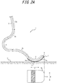
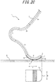
- FIGS. 2A , 2B , 2C and 2D are drawings for explaining in stages movement of the leg portion 2 and the ground contact form of the bottom surface 5s when the wearer who wears the athletic prosthetic leg 1 having the above configuration executes straight running.
- an upper portion is a side view of the leg portion 2 and the sole 5, and a lower portion illustrates a transition of the ground contact form of the bottom surface 5s when the wearer who wears the athletic prosthetic leg 1 executes straight running.
- FIG. 2A illustrates a state that the wearer lowers the raised athletic prosthetic leg 1 to the road surface S and the entire weight is loaded on the athletic prosthetic leg 1.
- a region at the side of the curved portion 3 from the point C contacts the ground.
- FIG. 2B illustrates a state that the wearer steps forward, from the state of FIG. 2A , while the entire weight remains to be loaded on the athletic prosthetic leg 1.
- a step form is generally applied that ground contact is sequentially executed from a heel side toward a toe side of a shoe sole which firstly contacts to the ground, while in the athletic prosthetic leg 1, the ground contact region is moved to the side of the curved portion 3 from a portion which firstly contacts the ground.
- FIG. 2C illustrates a state that the wearer starts a kick-out movement of the athletic prosthetic leg 1 by shaking an opposite leg from the leg wearing the athletic prosthetic leg 1 forward. Entering into this kick-out movement, the athletic prosthetic leg 1 contacts the ground at a region at the side of the toe T from the point C of the bottom surface 5s.
- FIG. 2D illustrates a state that the wearer is in a final stage of kicking out the athletic prosthetic leg 1 just before separating from the road surface S.
- ground contact is executed further at the side of the toe T than in FIG. 2C .
- the bottom surface 5s is divided into a curved portion side region Q1 and a toe side region Q2 with a border of the point C.
- FIG. 3 is a drawing for explaining each region of the bottom surface 5s, and the sole bottom surface 5s is illustrated in a plane.
- the curved portion side region Q1 is a region at the side of the curved portion 3 defined by a border as a line BL extending in the width direction W of the leg portion 2 through the point C in the bottom surface 5s.
- the curved portion side region Q1 is a region where the wearer firstly contacts the ground and executes a step movement in a state that the entire weight is loaded to the athletic prosthetic leg 1. Consequently, it is vital that the curved portion side region Q1 fully grips the road surface S such that the entire body is balanced even when the entire weight of the wearer is loaded on the athletic prosthetic leg 1.
- drainage performance of the curved portion side region Q1 needs to be higher than a portion other than the curved portion side region Q1, that is, the toe side region Q2.
- the sole 5 of the athletic prosthetic leg 1 prevents slip due to the water film and achieves a high anti-slip property.
- the toe side region Q2 is a region at the side of the toe T defined by the border as the line BL extending in the width direction W of the leg portion 2 through the point C in the bottom surface 5s.
- the toe side region Q2 is a region where the wearer shakes an opposite leg from a leg wearing the athletic prosthetic leg 1 forward to execute the kick-out movement of the athletic prosthetic leg 1.
- the toe side region Q2 sequentially contacts the ground toward the toe T, and the wearer presses the road surface S by the bottom surface 5s to slidingly contact the ground, so that the toe side region Q2 is a region which easily develops abrasion in particular.
- wear resistance performance of the toe side region Q2 needs to be higher than that of the curved portion side region Q1.
- each of the curved portion side region Q1 and the toe side region Q2 is further divided as illustrated in FIG. 3 based on the ground contact form illustrated in FIGS. 2A to 2D such that each portion has property corresponding to the ground contact form.
- a portion Q2-1 corresponds to the arc X1 which continues from the toe T with a constant radius of curvature in FIG. 1 .
- the portion Q2-1 finally contacts the ground when the wearer who wears the athletic prosthetic leg 1 executes the kick-out movement, so that severer abrasion has been inclined to occur.
- the portion Q2-1 needs to have an especially high wear resistance performance.
- the portion Q2-1 has a higher wear resistance performance than a remaining portion Q2-2, so that the sole 5 is protected from severe abrasion and the long service life of the leg portion 2 itself can be achieved.
- a portion Q1-1 at the side of the toe T from a center M1 of a maximum length L1 along the leg portion front-rear direction Y is a region which firstly contacts the ground, so that prevention of slip is especially necessary such that the wearer achieves a balance of his body.
- the portion Q1-1 preferably has a further higher drainage performance than a remaining portion Q1-2 in the curved portion side region Q1 such that slip is more surely prevented and a further stable running is achieved.
- the portion Q1-2 is a portion at the side of curved portion 3 from the center M1 of the maximum length L1.
- the ground contact portion is changed to the side of the curved portion 3 from the portion Q1-1 which firstly contacts the ground, that is, the portion Q1-2 at the opposite side from a direction that the wearer advances.
- the portion Q1-2 has a higher rigidity than the portion Q1-1. Since the portion Q1-2 has a higher rigidity than the portion Q1-1, the step movement is smoothly continued to the kick-out movement, and a high propulsive force can be achieved.
- the portion Q1-2 preferably has a larger edge component in the width direction W of the leg portion 2 than the portion Q1-1. Also, a negative ratio of the portion Q1-2 is preferably smaller than that of the portion Q1-1.
- the negative ratio refers to a percentage in an area of a recessed portion to the road surface S in a planar view in a total area of the bottom surface 5s in a planar view.
- the portion Q1-2 preferably has a larger edge component in the width direction W of the leg portion 2 than the toe side region Q2. Further, a negative ratio of the portion Q1-2 is preferably larger than that of the toe side region Q2. With this configuration, the portion Q1-2 can exert a high propulsive force when the wearer executes the kick-out movement.
- Concrete means to achieve the above-described properties to be applied to each portion of the bottom surface 5s includes, for example, designing a pattern constituted by recesses and protrusions by grooves and the like formed on the bottom surface 5s, designing the surface property of the bottom surface 5s, designing the cross-sectional shape of the sole 5 and designing the material of the sole 5.
- FIG. 4 is a drawing which illustrates a pattern of the bottom surface 5s of the sole 5 in the athletic prosthetic leg 1 according to this embodiment.
- a plurality of land portions 10 and a plurality of land portions 11 which are defined by a plurality of grooves extending in the width direction W are arranged in the curved portion side region Q1.
- the land portions 10 are arranged to the side of the toe T from the land portions 11.
- the land portions 10 are shaped to include a width direction extending portion 10a extending in the width direction W to be substantially zigzag-shaped, a toe side protruding portion 10b extending to the side of the toe T from a bent portion bending to be convex to the side of the toe T and a curved portion side protruding portion 10c extending to the side of the curved portion from a bent portion bending to be convex to the side of the curved portion 3.
- the land portions 11 are shaped to include a width direction extending portion 11a, a toe side protruding portion 11b and a curved portion side protruding portion 11c.
- the width direction extending portions 10a and 11a are zig-zag shaped, thereby fully ensuring the edge component. Further, by forming the toe side protruding portions 10b and 11b as well as the curved portion side protruding portions 10c and 11c, the edge component is further increased, and the water film interposed between the bottom surface 5s and the road surface S can be efficiently cut on both sides in the leg portion front-rear direction Y, thereby achieving a high drainage performance.
- a plurality of land portions 12 which are defined by a plurality of grooves extending in the width direction W are arranged in the toe side region Q2.
- the land portions 12 are shaped to include a width direction extending portion 12a extending in the width direction W to be substantially zig-zag shaped, a toe T side protruding portion 12b extending to be convex in a direction that the width direction extending portion 12a extends from a bent portion bending to be convex to the side of the toe T and a curved portion side protruding portion 12c extending to be convex in a direction that the width direction extending portion 12a extends from a bent portion bending to be convex to the side of the curved portion 3.
- a plurality of linear grooves 13 intermittently extending along the zig-zag shape extending in the width direction W are formed in the toe side region Q2.
- the land portions 12 are arranged to the side of the curved portion 3 from the linear grooves 13 and the linear grooves 13 are formed to the side of the toe T from the land portions 12.
- a land portion 14 having the same shape as the land portions 11 may be formed in the toe side region Q2.
- a land portion width w2 of the width direction extending portion 10a of the land portions 10 is larger than a land portion width w3 of the width direction extending portion 11a of the land portions 11.
- a land portion width w4 of the width direction extending portion 12a of the land portions 12 is larger than the land portion widths w2 and w3.
- a percentage in an area of a groove portion which is concave to the road surface S in a planar view in a total area of the bottom surface 5s in a planar view, that is, a negative ratio is larger than that in the toe side region Q2.
- a negative ratio is larger than that in the toe side region Q2.
- the toe side region Q2 has a higher wear resistance performance than the curved portion side region Q1. The reason is that the toe side region Q2 has a smaller negative ratio than the curved portion side region Q1 to maintain a high rigidity.
- the linear groove 13 is formed in the portion Q2-1.
- the ground contact portion Q2-1 has a larger rigidity than the remaining portion Q2-2 in the toe side region Q2 to include a further higher wear resistance performance.
- the negative ratio of the portion Q1-1 is larger than that of the portion Q1-2, so that more water can be taken in the grooves and can be discharged.
- the portion Q1-1 has a further higher drainage performance than the portion Q1-2.
- the land portions 11 are arranged in the portion Q1-2. Moreover, as described before, the land portion width w3 of the land portions 11 is larger than the land portion width w2 of the land portions 10. Thus, the portion Q1-2 has a larger land portion rigidity than the portion Q1-1. Further, the portion Q1-2 has a larger edge component in the width direction W than the portion Q1-1. Also, as described before, the negative ratio of the portion Q1-2 is smaller than that of the portion Q1-1.
- the portion Q1-2 has a larger edge component in the width direction W than the toe side region Q2 and further, has a larger negative ratio.
- a plurality of land portions 100, 110, 120 and 140 which are defined by a plurality of grooves extending in the width direction W are arranged.
- the land portions 100, 110, 120 and 140 correspond to the land portions 10, 11, 12 and 14 illustrated in FIG. 4 . While the same shape as that of the corresponding land portion is illustrated in a planar view of the bottom surface 50s, in a depth direction of the grooves defining each land portion, the land portions 100, 110, 120 and 140 have a two-stage structure. The two-stage structure will be explained with reference to the land portions 120.
- the land portions 120 have a step-like structure in which a second-stage block 120B is located above a first-stage block 120A at the side of the groove bottom in a thickness direction of the sole 5.
- a stepped portion of the first-stage block 120A is illustrated by a thick line in the drawing. While the second-stage block 120B has a smaller surface area than the first-stage block 120A in a planar view, the second-stage block 120B and the first-stage block 120A has the same shape.
- the land portions 100, 110 and 140 also include stepped portions illustrated by a thick line and have the step-like structure.
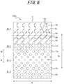
- a sole of an athletic prosthetic leg according to a third embodiment of the present disclosure will be explained with reference to FIG. 6 .
- a plurality of land portions 15 each having the shape of a square with rounded corners in a planar view are defined by forming a recessed groove in the portion Q1-1 of the curved portion side region Q1.
- land portions 16a and 16b are arranged at the side of the curved portion 3 from the land portions 15 in the curved portion side region Q1.
- the land portions 16a and 16b are applied the shape of a square with rounded corners in a planar view by forming a recessed groove in the bottom surface 500s, and have a larger area in the planar view than the land portions 15. Also, the land portion 16b has a larger area in a planar view than the land portion 16a. Further, land portions 17a and 17b having the same shape as the land portions 16a and 16b are defined also in the toe side region Q2.
- a land portion 18a having the shape of a rectangle with rounded corners in a planar view is formed in the toe side region Q2 at the side of the toe T from the land portions 17a and 17b, and a semi-land portion 18b is defined at the side of the toe T from the land portion 18a in an aspect that a depth of the groove is tapered toward the side of the toe T.
- a plurality of linear grooves 19a and a plurality of linear grooves 19b which are inclined to the width direction W are continuously arranged along the width direction W at the side of the toe T from the semi-land portion 18b.
- the linear grooves 19a and the linear grooves 19b are inclined in an opposite direction from each other to the width direction W.
- the curved portion side region Q1 and the toe side region Q2 illustrated in FIG. 6 can apply the same function as the curved portion side region Q1 and the toe side region Q2 in the sole of the athletic prosthetic leg according to the first embodiment and the second embodiment.
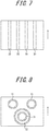
- each function is applied by the pattern constituted by recesses and protrusions of the bottom surface of the sole 5, the pattern is not limited to ones in the embodiments, and patterns illustrated below can be used. Each pattern will be explained with reference to FIGS. 7, 8 and 9 . Additionally, FIGS. 7 and 8 schematically illustrate pattern elements constituting a pattern by recesses and protrusions. By varying the number of the pattern elements or the specification thereof for every region or portion described above, a function required for each region and each portion can be applied.
- a pattern in which a plurality of vertical grooves 30 extending along the leg portion front-rear direction Y are formed can be used.
- water taken in the vertical grooves 30 flows accompanied with movement of the sole, so that the water can be efficiently discharged from an end portion of the vertical grooves 30.
- a pattern which prioritizes any of drainage performance and wear resistance performance can be applied.
- a pattern in which a plurality of grooves 31 and 32 continuing annularly are formed can be used. Due to the annular grooves 31 and 32, intake and discharge of water can be efficiently executed irrespective of a direction of various inputs of force acting on the bottom surface of the sole 5. By varying the width, depth or diameter of a ring of the annular grooves 31 and 32 for each portion of the bottom surface 5s, a pattern which prioritizes any of drainage performance and wear resistance can be applied.
- the bottom surface of the sole 5 may have a pattern in which only the vertical grooves or the only the annular grooves are formed, or a pattern with a combination of the vertical grooves and the annular grooves. Further, a pattern with a combination of the annular grooves and lateral grooves may be applied.
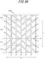
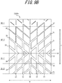
- a pattern illustrated in FIG. 9A or 9B can be used as a pattern of the bottom surface of the sole 5.
- a pattern illustrated in FIG. 9A or 9B can be used.
- a plurality of vertical grooves 33 which are open at one end or both ends are formed at sole end edges at the side of the toe T as well as the side of the curved portion 3, and a plurality of inclined grooves 34, 35, 36 and 37 which communicate with the vertical grooves 33, inclinedly extend in the width direction W and are open at the sole end edges are formed.
- the inclined grooves 34, 35 extend inclinedly to the side of the curved portion 3 from the center in the width direction W of the bottom surface 5000s toward the sole end edges.
- the inclined grooves 36, 37 extend inclinedly to the side of the toe T from the center in the width direction W of the bottom surface 5000s toward the sole end edges.
- a ground contact portion is changed to the portion Q1-2 at the side of the curved portion 3 from the portion Q1-1 which firstly contacts the ground.
- water taken in the grooves flows along the inclination of the grooves from the side of toe T to the side of the curved portion 3, and is discharged from an opening at an end edge of the bottom surface 5000s.
- the water taken in the grooves flows along the inclination of the grooves from the side of the curved portion 3 to the side of the toe T, and is discharged from an opening at an end edge of the sole 5.
- efficient drainage can be achieved. While the groove width of each groove is constant in FIG. 9A , in FIG. 9B , the groove width is enlarged in a region in which drainage performance is prioritized, while the groove width is reduced in a region in which wear resistance performance is prioritized.
- the depth of the groove and the number of grooves formed at the bottom surface of the sole 5 is arbitrary. By enlarging the depth of the groove, the drainage performance can be more improved. Further, the drainage performance can be also improved by increasing the number of grooves.
- the wear resistance performance and the drainage performance can be controlled for each region and each portion by designing the surface property of the bottom surface of the sole 5, for example, varying the introduction density of a sipe, the surface roughness and a riblet and the like illustrated below.
- the drainage performance can be improved by forming a plurality of sipes which is narrower than grooves on the bottom surface of the sole 5.
- this relation may be reversed. The same comment is applied to the surface roughness and the riblet below.
- the surface roughness is adjusted by applying micro recesses and protrusions to the bottom surface of the sole 5, thereby improving the drainage performance and the wear resistance performance.
- a coarser surface roughness is used, water can be taken in the micro recesses and protrusions, so that a high drainage performance can be achieved.
- riblets in which fine grooves are continuously aligned in the width direction W or the leg portion front-rear direction Y, water interposed between the road surface S and the sole 5 sequentially infiltrates each narrow groove of the riblet due to capillary action, so that a higher drainage performance can be achieved.
- water applied to a surface of the bottom surface of the sole 5 can be efficiently eliminated, so that the drainage performance can be improved.
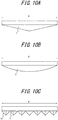
- FIGS. 10A, 10B and 10C are schematic cross-sectional views along the width direction W of the sole 5.
- the thickness of the sole 5 is largest at the center in the width direction W, and it is tapered toward the side of the sole end edge in the width direction W.
- the sole 5 may have the shape in which the thickness is linearly tapered as illustrated in FIG. 10A , while it may have the shape in which the thickness is tapered in an arc as illustrated in FIG. 10B .
- the entire sole 5 may have this configuration, or only a part of the sole 5 may have this configuration.
- the sole 5 may have a structure that it has a plurality of cones which are convex to the ground contact side.
- the sole 5 has a plurality of quadrangular pyramids 40 which are convex to the ground contact side.
- the bottom surface of the sole 5 is spike-like, which achieves ground contact from an apex by efficiently cutting a water film existing between the bottom surface of the sole 5 and the road surface S. Consequently, a high drainage performance can be achieved.
- the water can pass through a gap formed between the plurality of quadrangular pyramids 40, a high drainage performance can be achieved.
- a cone or polygonal cones other than a quadrangular pyramid may be applied.
- wear resistance performance can also be achieved by varying the size of a pyramid in accordance with each region of the bottom surface of the sole 5.
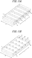
- FIGS. 11A and 11B are perspective views illustrating the ground contact portion 4 and the sole 5.
- the sole 5 has a hidden groove 41 which is open to the side of the ground contact portion 4 at the side of a border surface between the ground contact portion 4 and the sole 5.
- the hidden groove 41 extends along the width direction W to be open at both end edges of the sole 5. With this configuration, water on the road surface is taken in the hidden groove 41 from both ends of the leg portion 2 in the width direction W and discharged. This prevents the water from infiltrating a portion between the bottom surface of the sole 5 and the road surface S, so that a high drainage performance can be obtained.
- the sole 5 is formed with a groove or a recess portion which is open to the side of the adhesive at the side of a border surface with the adhesive.
- the sole 5 may have the configuration that includes a combined groove in which a circular groove 42 formed on the bottom surface of the sole 5 communicates with a groove 43 penetrating through the sole 5 along the width direction W.
- a combined groove in which a circular groove 42 formed on the bottom surface of the sole 5 communicates with a groove 43 penetrating through the sole 5 along the width direction W.
- each function is applied by designing a part or the entire of the material of the sole 5 .
- felt a sponge or non-woven fabric is used to a part or the entire of the sole 5 and drainage performance can be improved due to a water absorption operation of each material.
- the same effect can be obtained by using foamed rubber to a part or the entire of the sole 5 due to a water abrasion operation of the foamed rubber.
- the sole 5 of the athletic prosthetic leg 1 according to the present disclosure explained so far can be manufactured, for example, by a method of processing a rubber sheet by a laser light, a method of using a mold and a manufacturing method using a 3D printer.
- the sole 5 is attached to the ground contact region 4s via an adhesive.
- attachment means is not limited to the adhesive, and attachment may be executed using fasteners such as a belt.
- a cushion member (not shown) or a binding material may be interposed between the sole 5 and the ground contact region 4s.
- FIG. 12A is a perspective view which illustrates the sole 5 and a tab for sticking before the sole 5 is attached to the ground contact portion 4. Additionally, in FIG. 12A , a pattern of the bottom surface 5s is omitted. As illustrated, a toe-side tab for sticking 6 and a curved-portion-side tab for sticking 7 are integrally connected to the sole 5. The toe-side tab for sticking 6 is fan-shaped and connected along an end edge at the side of the toe T of the sole 5, and moreover, is divided by two cuts 8a, 8b.
- FIG. 12B is a drawing for explaining thicknesses at a border between the toe-side tab for sticking 6 and the sole 5 and at a portion adjacent to the border.
- FIG. 12C is a drawing for explaining the thicknesses at a border between the curved-portion-side tab for sticking 7 and the sole 5 and at a portion adjacent to the border.
- the toe-side tab for sticking 6 extends with a constant thickness th2 which is thinner than a thickness th1 of the sole 5, and the thickness gradually increases toward a border B1 with the sole 5.
- the curved-portion-side tab for sticking 7 extends with a thickness th3 which is thinner than the thickness th1 of the sole 5, and the thickness gradually increases toward a border B2 with the sole 5.
- the thickness th1 of the sole 5 is 2.25 to 3.0 mm
- the thickness th2 of the toe-side tab for sticking 6 and the thickness th3 of the curved-portion-side tab for sticking 7 may be 1.5 to 2.0 mm.
- Prototypes are produced for each of soles of Examples and soles of comparative examples, and performance evaluation is executed.
- the soles of Examples are applied a function such as drainage performance specified in the present disclosure due to variation of an arrangement of the pattern or the grooves of the bottom surface of the sole.
- a pattern of the sole is uniform at the bottom surface.
- a pattern is different from that of the present disclosure.
- an index of the comparative example 1 is 100, it is presented that anti-slip property is excellent as the index increases.
- a player with a healthy left leg wears an athletic prosthetic leg at a right side, and executes 200 km running on a public road, and thereafter, indexation of an appearance of the entire bottom surface is executed. Additionally, assuming that an index of the comparative example 1 is 100, it is presented that the sole has an excellent wear resistance performance as the index increases.
- a player with a healthy left leg wore the athletic prosthetic leg at a right side and executed 200 km running on a public road, and thereafter, indexation of an appearance of the entire bottom surface was executed. Also, in the comparative example 2 and Examples 1 to 3, indexation of the appearance of the entire bottom surface is executed by the same method as in the comparative example 1 and Example 4.
Landscapes
- Health & Medical Sciences (AREA)
- Transplantation (AREA)
- Vascular Medicine (AREA)
- Life Sciences & Earth Sciences (AREA)
- Oral & Maxillofacial Surgery (AREA)
- Engineering & Computer Science (AREA)
- Biomedical Technology (AREA)
- Heart & Thoracic Surgery (AREA)
- Orthopedic Medicine & Surgery (AREA)
- Cardiology (AREA)
- Animal Behavior & Ethology (AREA)
- General Health & Medical Sciences (AREA)
- Public Health (AREA)
- Veterinary Medicine (AREA)
- Prostheses (AREA)
- Tires In General (AREA)
Abstract
Description
- The present disclosure relates to a sole attached to a ground contact region of an athletic prosthetic leg, in particular, to a sole of an athletic prosthetic leg which inhibits slip of the prosthetic leg during a competition.
- Conventionally, a prosthetic leg for a competition (hereinafter, referred to as an athletic prosthetic leg or simply referred to as a prosthetic leg) having a leaf-spring-like leg portion which extends via a curved portion to a side of a toe and in which a ground contact region extends from the toe to a side of the curved portion in an arc has been well-known. To such an athletic prosthetic leg having the leaf-spring-like leg portion, generally, a sole which abuts a road surface is attached to a bottom surface of the ground contact region.
- For example,
Patent Literature 1 illustrates a sole which is attached to a lower surface of a curved leaf-spring-like athletic prosthetic leg to correspond to sporting events such as jogging or running. In other words,Patent Literature 1 discloses a sole to which a spike is attached at a lower surface of the sole contacting a road surface or a sole provided with a number of outsole portions each having a hexagonal contact patch. - PTL 1: Japanese Patent Laid-Open No.
2016-150189 - However, in the sole illustrated in
Patent Literature 1, inhibiting slip of the prosthetic leg, that is, anti-slip property is not at all considered. For example, running on a wet road surface is required in a case of a competition in rainfall etc. At that time, when a water film exists on the road surface, the water film is interposed between a bottom surface of the sole and the road surface while hindering ground contact of the bottom surface, resulting that slip is caused. Especially, on a road with a low coefficient friction µ such as asphalt and a stone pavement, there has been a case where a wearer of the prosthetic leg hesitates further acceleration. Accordingly, a sole having a high anti-slip property has been required for the wearer of the prosthetic leg to satisfactorily exert his running skill as athletes. - An object of the present disclosure is to provide a sole of an athletic prosthetic leg having a high anti-slip property.
- The inventor earnestly studied means to solve the problem. In other words, while a ground contact form of an athletic prosthetic leg has been reviewed in detail, the inventor newly found that the athletic prosthetic leg illustrates a unique ground contact form caused by the shape of a leaf-spring-like leg portion. Further, the inventor found that a high anti-slip property can be achieved by allowing a bottom surface of a sole to correspond to a ground contact form which is unique to the athletic prosthetic leg to separate functions of the sole, and completed the present disclosure.
- According to the present disclosure, there is provided a sole of an athletic prosthetic leg, the athletic prosthetic leg having a leaf-spring-like leg portion extending to a side of a toe via at least one curved portion, the sole being configured to be attached to a ground contact region of the athletic prosthetic leg, the ground contact region extending from the toe to a side of the curved portion in an arc, wherein the sole includes a bottom surface having a shape conforming to an extending shape of the ground contact region, and, in the bottom surface, a region at the side of the curved portion has a higher drainage performance compared with a region other than the region at the side of the curved portion, the region at the side of the curved portion being defined by a border as a line extending in a width direction of the leg portion through a contact point with a road surface in a standing state of a wearer who wears the athletic prosthetic leg.
- Due to the present disclosure, a sole of an athletic prosthetic leg having a high anti-slip property can be provided. Attachment of this sole to the athletic prosthetic leg provides an effect of fully exerting an athlete's skill.
- In the accompanying drawings:
-
FIG. 1 is a side view of an athletic prosthetic leg to which a sole according to a first embodiment of the present disclosure is attached; -
FIG. 2A is a drawing for explaining in stages movement of a leg portion and a ground contact form in a case where the athletic prosthetic leg is worn and a wearer executes straight running; -
FIG. 2B is a drawing for explaining in stages the movement of the leg portion and the ground contact form in a case where the athletic prosthetic leg is worn and the wearer executes straight running; -
FIG. 2C is a drawing for explaining in stages the movement of the leg portion and the ground contact form in a case where the athletic prosthetic leg is worn and the wearer executes straight running; -
FIG. 2D is a drawing for explaining in stages the movement of the leg portion and the ground contact form in a case where the athletic prosthetic leg is worn and the wearer executes straight running; -
FIG. 3 is a drawing for explaining each region of a bottom surface; -
FIG. 4 is a drawing which illustrates a pattern of the bottom surface of the sole of the athletic prosthetic leg according to the first embodiment; -
FIG. 5 is a drawing which illustrates a pattern of the bottom surface of the sole of the athletic prosthetic leg according to a second embodiment; -
FIG. 6 is a drawing which illustrates a pattern of the bottom surface of the sole of the athletic prosthetic leg according to a third embodiment; -
FIG. 7 is a drawing which schematically illustrates a pattern element constituting a pattern by recesses and protrusions; -
FIG. 8 is a drawing which schematically illustrates a pattern element constituting a pattern by recesses and protrusions; -
FIG. 9A is a drawing which illustrates the bottom surface of the sole to which a pattern by recesses and protrusions is applied; -
FIG. 9B is a drawing which illustrates the bottom surface of the sole to which a pattern by recesses and protrusions is applied; -
FIG. 10A is a schematic cross-sectional view along a width direction of the leg portion of the sole; -
FIG. 10B is a schematic cross-sectional view along the width direction of the leg portion of the sole; -
FIG. 10C is a schematic cross-sectional view along the width direction of the leg portion of the sole; -
FIG. 11A is a perspective view which illustrates a ground contact portion and the sole; -
FIG. 11B is a perspective view which illustrates the ground contact portion and the sole; -
FIG. 12A is a perspective view which illustrates the sole and a tab for sticking before the sole is mounted to the ground contact portion; -
FIG. 12B is a drawing for explaining the thicknesses at a border between a toe-side tab for sticking and the sole and at a portion adjacent to the border; and -
FIG. 12C is a drawing for explaining the thicknesses at a border between a curved-portion-side tab for sticking and the sole and at a portion adjacent to the border. - Hereinafter, with reference to the drawings, a sole of an athletic prosthetic leg of the present disclosure (hereinafter, it is also referred to as a sole) will be explained in detail with illustration of embodiments thereof.
-
FIG. 1 is a side view of an athleticprosthetic leg 1 to which a sole 5 according to a first embodiment of the present disclosure is attached. Theathletic prosthetic leg 1 has a leaf-spring-like leg portion 2, and the sole 5 is attached to a ground contact region at its tip side. Additionally, while illustration is omitted, a base end portion of theleg portion 2 is connected to a socket via an adapter and the socket houses a stump of a wearer's leg, whereby the wearer can wear the prosthetic leg. The adapter and the socket which correspond to the position of the stump of the leg, such as an above-knee prosthesis and a below-knee prosthesis, are used.FIG. 1 illustrates theleg portion 2 and the sole 5 in a standing state of the wearer who wears the athleticprosthetic leg 1. - Hereinafter, in this embodiment, in a height direction of the athletic prosthetic leg, a side where the
leg portion 2 is connected to the adapter is referred to as a connection side, and a side where theleg portion 2 contacts a road surface S is referred to as a ground contact side. Also, a toe T of the athleticprosthetic leg 1 refers to a point at the forefront as a termination of theleg portion 2 extending from the connection side. Further, a direction extending from the toe T in parallel with the road surface S is referred to as a leg portion front-rear direction Y. Further, a widthwise direction of theleg portion 2 is referred to as a width direction W. - In this embodiment, the
leg portion 2 of the athleticprosthetic leg 1 has a plate-like extending shape to the side of the toe T via at least one curved portion, in the illustrated example, onecurved portion 3. InFIG. 1 , theleg portion 2 is constituted by, in the order from the connecting side to the ground contact side, astraight portion 2a, acurved portion 2b which is convex to the side of the toe T, thecurved portion 3 which is convex to a rear side in the leg portion front-rear direction Y, acurved portion 2c which is concave to the ground contact side and aground contact portion 4 which is convex to the ground contact side to extend to the side of the toe T in an arc. - Additionally, although the material of the
leg portion 2 is not limited, from a viewpoint of strength and weight saving, fiber reinforced plastic etc. is preferably used. - The
ground contact portion 4 includes aground contact region 4s extending from the toe T to the side of thecurved portion 3 in an arc at the ground contact side, and the sole 5 is attached to theground contact region 4s. Theground contact region 4s refers to the entire region abutting the road surface S when the wearer who wears the athleticprosthetic leg 1 executes straight running movement, and in a state that sole 5 is attached, theground contact region 4s abuts the road surface S via the sole 5. - The sole 5 has a shape conforming to an extending shape of the
ground contact region 4s. Also, the ground contact side of the sole 5 is abottom surface 5s. As illustrated inFIG. 1 , thebottom surface 5s has a shape in which an arc X1 and an arc X2 are continued from the toe T side to thecurved portion 3 side. While the arc X1 and the arc X2 have a different radius of curvature to each other in this embodiment, they may include the same radius of curvature. - Also, the
bottom surface 5s has different properties at one side and the other side, which are defined by a border as a line extending in the width direction W through a point C as a contact point with the road surface S in a standing state of the wearer when the athleticprosthetic leg 1 is worn. The point C is a point which firstly contacts the road surface S in arriving at standing. In other words, the standing state refers to a state that the wearer firstly contacts the road surface S by lowering the athleticprosthetic leg 1 to the road surface S from a state that the wearer supports his body by a healthy leg wearing no prosthetic leg when a prosthetic leg is used for only one leg, or the wearer supports his body by one prosthetic leg when prosthetic legs are used for both legs. Additionally, the point C is determined depending on the shape or an attachment aspect etc. of the prosthetic leg. In other words, the inventor newly conceived that the border for separating functions of thebottom surface 5s from a finding related to a ground contact form obtained from an experiment which will be described later uses the point C which is the contact point with the road surface S in the wearer's standing state as a standard. - An experiment result of the ground contact form of the
bottom surface 5s as described above will be explained below usingFIGS. 2A ,2B ,2C and2D .FIGS. 2A ,2B ,2C and2D are drawings for explaining in stages movement of theleg portion 2 and the ground contact form of thebottom surface 5s when the wearer who wears the athleticprosthetic leg 1 having the above configuration executes straight running. In each drawing, an upper portion is a side view of theleg portion 2 and the sole 5, and a lower portion illustrates a transition of the ground contact form of thebottom surface 5s when the wearer who wears the athleticprosthetic leg 1 executes straight running. - In other words,
FIG. 2A illustrates a state that the wearer lowers the raised athleticprosthetic leg 1 to the road surface S and the entire weight is loaded on the athleticprosthetic leg 1. As illustrated in the lower portion of the drawing, in thebottom surface 5s, a region at the side of thecurved portion 3 from the point C contacts the ground. -
FIG. 2B illustrates a state that the wearer steps forward, from the state ofFIG. 2A , while the entire weight remains to be loaded on the athleticprosthetic leg 1. In a case of running of a healthy person, such a step form is generally applied that ground contact is sequentially executed from a heel side toward a toe side of a shoe sole which firstly contacts to the ground, while in the athleticprosthetic leg 1, the ground contact region is moved to the side of thecurved portion 3 from a portion which firstly contacts the ground. -
FIG. 2C illustrates a state that the wearer starts a kick-out movement of the athleticprosthetic leg 1 by shaking an opposite leg from the leg wearing the athleticprosthetic leg 1 forward. Entering into this kick-out movement, the athleticprosthetic leg 1 contacts the ground at a region at the side of the toe T from the point C of thebottom surface 5s. -
FIG. 2D illustrates a state that the wearer is in a final stage of kicking out the athleticprosthetic leg 1 just before separating from the road surface S. To kick out from the toe T of thebottom surface 5s, ground contact is executed further at the side of the toe T than inFIG. 2C . - Based on the experimental result illustrated in
FIGS. 2A ,2B ,2C and2D , as illustrated inFIG. 3 , firstly, thebottom surface 5s is divided into a curved portion side region Q1 and a toe side region Q2 with a border of the point C. Additionally,FIG. 3 is a drawing for explaining each region of thebottom surface 5s, and the solebottom surface 5s is illustrated in a plane. - In other words, the curved portion side region Q1 is a region at the side of the
curved portion 3 defined by a border as a line BL extending in the width direction W of theleg portion 2 through the point C in thebottom surface 5s. As illustrated inFIGS. 2A and2B , the curved portion side region Q1 is a region where the wearer firstly contacts the ground and executes a step movement in a state that the entire weight is loaded to the athleticprosthetic leg 1. Consequently, it is vital that the curved portion side region Q1 fully grips the road surface S such that the entire body is balanced even when the entire weight of the wearer is loaded on the athleticprosthetic leg 1. Thus, to prevent slip due to a water film interposed between thebottom surface 5s and the road surface S, drainage performance of the curved portion side region Q1 needs to be higher than a portion other than the curved portion side region Q1, that is, the toe side region Q2. - In other words, since the curved portion side region Q1 has a higher drainage performance compared with the portion other than the curved portion side region Q1, the sole 5 of the athletic
prosthetic leg 1 prevents slip due to the water film and achieves a high anti-slip property. - On the other hand, the toe side region Q2 is a region at the side of the toe T defined by the border as the line BL extending in the width direction W of the
leg portion 2 through the point C in thebottom surface 5s. The toe side region Q2 is a region where the wearer shakes an opposite leg from a leg wearing the athleticprosthetic leg 1 forward to execute the kick-out movement of the athleticprosthetic leg 1. The toe side region Q2 sequentially contacts the ground toward the toe T, and the wearer presses the road surface S by thebottom surface 5s to slidingly contact the ground, so that the toe side region Q2 is a region which easily develops abrasion in particular. Thus, wear resistance performance of the toe side region Q2 needs to be higher than that of the curved portion side region Q1. - In other words, with the toe side region Q2 having a higher wear resistance performance than the curved portion side region Q1, early abrasion of the toe side region Q2 is avoided, and as a result, the entire surface of the sole 5 of the athletic
prosthetic leg 1 is gently worn and a long service life of the sole 5 can be achieved. - Also, it is preferable that each of the curved portion side region Q1 and the toe side region Q2 is further divided as illustrated in
FIG. 3 based on the ground contact form illustrated inFIGS. 2A to 2D such that each portion has property corresponding to the ground contact form. - In other words, of the toe side region Q2 illustrated in
FIG. 3 , a portion Q2-1 corresponds to the arc X1 which continues from the toe T with a constant radius of curvature inFIG. 1 . The portion Q2-1 finally contacts the ground when the wearer who wears the athleticprosthetic leg 1 executes the kick-out movement, so that severer abrasion has been inclined to occur. Thus, the portion Q2-1 needs to have an especially high wear resistance performance. In other words, in the toe side region Q2, the portion Q2-1 has a higher wear resistance performance than a remaining portion Q2-2, so that the sole 5 is protected from severe abrasion and the long service life of theleg portion 2 itself can be achieved. - Next, in the curved portion side region Q1, a portion Q1-1 at the side of the toe T from a center M1 of a maximum length L1 along the leg portion front-rear direction Y is a region which firstly contacts the ground, so that prevention of slip is especially necessary such that the wearer achieves a balance of his body. Thus, the portion Q1-1 preferably has a further higher drainage performance than a remaining portion Q1-2 in the curved portion side region Q1 such that slip is more surely prevented and a further stable running is achieved.
- Also, the portion Q1-2 is a portion at the side of
curved portion 3 from the center M1 of the maximum length L1. As illustrated inFIG. 2B , in the curved portion side region Q1, the ground contact portion is changed to the side of thecurved portion 3 from the portion Q1-1 which firstly contacts the ground, that is, the portion Q1-2 at the opposite side from a direction that the wearer advances. At the time of ground contact of the portion Q1-2, movement of an upper body in which the wearer tries to move forward and movement of the ground contact portion are temporarily opposite, so that a high propulsive force is needed for the kick-out movement at the latter half of the ground contact form. Consequently, firstly, it is vital that the portion Q1-2 has a higher rigidity than the portion Q1-1. Since the portion Q1-2 has a higher rigidity than the portion Q1-1, the step movement is smoothly continued to the kick-out movement, and a high propulsive force can be achieved. - Especially, in a case where the
bottom surface 5s includes a pattern constituted by a plurality of recesses and protrusions, the portion Q1-2 preferably has a larger edge component in the width direction W of theleg portion 2 than the portion Q1-1. Also, a negative ratio of the portion Q1-2 is preferably smaller than that of the portion Q1-1. Here, the negative ratio refers to a percentage in an area of a recessed portion to the road surface S in a planar view in a total area of thebottom surface 5s in a planar view. With this configuration, a high propulsive force can be exerted in running. - Also, to exert the propulsive force effectively, the portion Q1-2 preferably has a larger edge component in the width direction W of the
leg portion 2 than the toe side region Q2. Further, a negative ratio of the portion Q1-2 is preferably larger than that of the toe side region Q2. With this configuration, the portion Q1-2 can exert a high propulsive force when the wearer executes the kick-out movement. - Concrete means to achieve the above-described properties to be applied to each portion of the
bottom surface 5s includes, for example, designing a pattern constituted by recesses and protrusions by grooves and the like formed on thebottom surface 5s, designing the surface property of thebottom surface 5s, designing the cross-sectional shape of the sole 5 and designing the material of the sole 5. - Hereinafter, firstly, the first embodiment and a second embodiment will be explained about a case where each function is applied by design of the pattern constituted by recesses and protrusions of the
bottom surface 5s.FIG. 4 is a drawing which illustrates a pattern of thebottom surface 5s of the sole 5 in the athleticprosthetic leg 1 according to this embodiment. - In the pattern illustrated in
FIG. 4 , a plurality ofland portions 10 and a plurality ofland portions 11 which are defined by a plurality of grooves extending in the width direction W are arranged in the curved portion side region Q1. Theland portions 10 are arranged to the side of the toe T from theland portions 11. Theland portions 10 are shaped to include a widthdirection extending portion 10a extending in the width direction W to be substantially zigzag-shaped, a toeside protruding portion 10b extending to the side of the toe T from a bent portion bending to be convex to the side of the toe T and a curved portionside protruding portion 10c extending to the side of the curved portion from a bent portion bending to be convex to the side of thecurved portion 3. Theland portions 11 are shaped to include a widthdirection extending portion 11a, a toeside protruding portion 11b and a curved portionside protruding portion 11c. The widthdirection extending portions side protruding portions side protruding portions bottom surface 5s and the road surface S can be efficiently cut on both sides in the leg portion front-rear direction Y, thereby achieving a high drainage performance. - Also, in
FIG. 4 , a plurality ofland portions 12 which are defined by a plurality of grooves extending in the width direction W are arranged in the toe side region Q2. Theland portions 12 are shaped to include a widthdirection extending portion 12a extending in the width direction W to be substantially zig-zag shaped, a toe Tside protruding portion 12b extending to be convex in a direction that the widthdirection extending portion 12a extends from a bent portion bending to be convex to the side of the toe T and a curved portionside protruding portion 12c extending to be convex in a direction that the widthdirection extending portion 12a extends from a bent portion bending to be convex to the side of thecurved portion 3. Further, a plurality oflinear grooves 13 intermittently extending along the zig-zag shape extending in the width direction W are formed in the toe side region Q2. Theland portions 12 are arranged to the side of thecurved portion 3 from thelinear grooves 13 and thelinear grooves 13 are formed to the side of the toe T from theland portions 12. Additionally, as illustrated in the drawing, aland portion 14 having the same shape as theland portions 11 may be formed in the toe side region Q2. - In
FIG. 4 , a land portion width w2 of the widthdirection extending portion 10a of theland portions 10 is larger than a land portion width w3 of the widthdirection extending portion 11a of theland portions 11. Also, a land portion width w4 of the widthdirection extending portion 12a of theland portions 12 is larger than the land portion widths w2 and w3. - In this configuration, in the curved portion side region Q1, a percentage in an area of a groove portion which is concave to the road surface S in a planar view in a total area of the
bottom surface 5s in a planar view, that is, a negative ratio is larger than that in the toe side region Q2. Thus, in the curved portion side region Q1, more water can be taken in a recessed groove and can be discharged. Thus, the curved portion side region Q1 has a higher drainage performance than the toe side region Q2. - On the other hand, the toe side region Q2 has a higher wear resistance performance than the curved portion side region Q1. The reason is that the toe side region Q2 has a smaller negative ratio than the curved portion side region Q1 to maintain a high rigidity.
- Additionally, in the toe side region Q2, the
linear groove 13 is formed in the portion Q2-1. With this configuration, the ground contact portion Q2-1 has a larger rigidity than the remaining portion Q2-2 in the toe side region Q2 to include a further higher wear resistance performance. - Also, in
FIG. 4 , in the curved portion side region Q1, the negative ratio of the portion Q1-1 is larger than that of the portion Q1-2, so that more water can be taken in the grooves and can be discharged. In other words, the portion Q1-1 has a further higher drainage performance than the portion Q1-2. - Further, in the curved portion side region Q1, the
land portions 11 are arranged in the portion Q1-2. Moreover, as described before, the land portion width w3 of theland portions 11 is larger than the land portion width w2 of theland portions 10. Thus, the portion Q1-2 has a larger land portion rigidity than the portion Q1-1. Further, the portion Q1-2 has a larger edge component in the width direction W than the portion Q1-1. Also, as described before, the negative ratio of the portion Q1-2 is smaller than that of the portion Q1-1. - Also, the portion Q1-2 has a larger edge component in the width direction W than the toe side region Q2 and further, has a larger negative ratio.
- Next, a sole of an athletic prosthetic leg according to the second embodiment of the present disclosure will be explained with reference to
FIG. 5 . In the sole of the athletic prosthetic leg according to the second embodiment, properties included by each portion of the sole are the same as in the first embodiment. - In a
bottom surface 50s of the sole 5 illustrated inFIG. 5 , a plurality ofland portions land portions land portions FIG. 4 . While the same shape as that of the corresponding land portion is illustrated in a planar view of thebottom surface 50s, in a depth direction of the grooves defining each land portion, theland portions land portions 120. Theland portions 120 have a step-like structure in which a second-stage block 120B is located above a first-stage block 120A at the side of the groove bottom in a thickness direction of the sole 5. A stepped portion of the first-stage block 120A is illustrated by a thick line in the drawing. While the second-stage block 120B has a smaller surface area than the first-stage block 120A in a planar view, the second-stage block 120B and the first-stage block 120A has the same shape. In a case where the wearer who wears the athleticprosthetic leg 1 executes straight running movement, when the second-stage block 120B firstly contacts the ground to be crushed, water interposed between the first-stage block 120A and the road surface S is pushed out to the side of the road surface S, thereby discharging the water effectively. Further, the first-stage block 120A contacts the ground after the second-stage block 120B, which fully ensures a foot print area with the road surface S while drainage performance is not deteriorated. Theland portions - Next, a sole of an athletic prosthetic leg according to a third embodiment of the present disclosure will be explained with reference to
FIG. 6 . In abottom surface 500s of the sole 5 of the athletic prosthetic leg according to the third embodiment, a plurality ofland portions 15 each having the shape of a square with rounded corners in a planar view are defined by forming a recessed groove in the portion Q1-1 of the curved portion side region Q1. Also,land portions curved portion 3 from theland portions 15 in the curved portion side region Q1. Theland portions bottom surface 500s, and have a larger area in the planar view than theland portions 15. Also, theland portion 16b has a larger area in a planar view than theland portion 16a. Further,land portions land portions land portion 18a having the shape of a rectangle with rounded corners in a planar view is formed in the toe side region Q2 at the side of the toe T from theland portions semi-land portion 18b is defined at the side of the toe T from theland portion 18a in an aspect that a depth of the groove is tapered toward the side of the toe T. Moreover, a plurality oflinear grooves 19a and a plurality oflinear grooves 19b which are inclined to the width direction W are continuously arranged along the width direction W at the side of the toe T from thesemi-land portion 18b. Thelinear grooves 19a and thelinear grooves 19b are inclined in an opposite direction from each other to the width direction W. - With this configuration, the curved portion side region Q1 and the toe side region Q2 illustrated in
FIG. 6 can apply the same function as the curved portion side region Q1 and the toe side region Q2 in the sole of the athletic prosthetic leg according to the first embodiment and the second embodiment. - Additionally, in the case where each function is applied by the pattern constituted by recesses and protrusions of the bottom surface of the sole 5, the pattern is not limited to ones in the embodiments, and patterns illustrated below can be used. Each pattern will be explained with reference to
FIGS. 7, 8 and9 . Additionally,FIGS. 7 and 8 schematically illustrate pattern elements constituting a pattern by recesses and protrusions. By varying the number of the pattern elements or the specification thereof for every region or portion described above, a function required for each region and each portion can be applied. - For example, as illustrated in
FIG. 7 , a pattern in which a plurality ofvertical grooves 30 extending along the leg portion front-rear direction Y are formed can be used. With this configuration, water taken in thevertical grooves 30 flows accompanied with movement of the sole, so that the water can be efficiently discharged from an end portion of thevertical grooves 30. By varying the width or the depth of thevertical grooves 30 for each portion of the bottom surface of the sole 5, a pattern which prioritizes any of drainage performance and wear resistance performance can be applied. - Also, as illustrated in
FIG. 8 , a pattern in which a plurality ofgrooves annular grooves annular grooves bottom surface 5s, a pattern which prioritizes any of drainage performance and wear resistance can be applied. - Additionally, the bottom surface of the sole 5 may have a pattern in which only the vertical grooves or the only the annular grooves are formed, or a pattern with a combination of the vertical grooves and the annular grooves. Further, a pattern with a combination of the annular grooves and lateral grooves may be applied.
- Further, as a pattern of the bottom surface of the sole 5, a pattern illustrated in
FIG. 9A or9B can be used. In this pattern, in abottom surface 5000s of the sole 5, a plurality ofvertical grooves 33 which are open at one end or both ends are formed at sole end edges at the side of the toe T as well as the side of thecurved portion 3, and a plurality ofinclined grooves vertical grooves 33, inclinedly extend in the width direction W and are open at the sole end edges are formed. As illustrated in the drawing, in the curved portion side region Q1, theinclined grooves curved portion 3 from the center in the width direction W of thebottom surface 5000s toward the sole end edges. On the other hand, in the toe side region Q2, theinclined grooves bottom surface 5000s toward the sole end edges. With this configuration, drainage performance in accordance with the ground contact form of the athleticprosthetic leg 1 can be achieved. In other words, in thebottom surface 5000s, a ground contact portion is changed to the portion Q1-2 at the side of thecurved portion 3 from the portion Q1-1 which firstly contacts the ground. In accordance with a transition movement, water taken in the grooves flows along the inclination of the grooves from the side of toe T to the side of thecurved portion 3, and is discharged from an opening at an end edge of thebottom surface 5000s. Further, accompanied with a transition movement of the ground contact portion from the curved portion side region Q1 to the toe side region Q2, the water taken in the grooves flows along the inclination of the grooves from the side of thecurved portion 3 to the side of the toe T, and is discharged from an opening at an end edge of the sole 5. With this operation, efficient drainage can be achieved. While the groove width of each groove is constant inFIG. 9A , inFIG. 9B , the groove width is enlarged in a region in which drainage performance is prioritized, while the groove width is reduced in a region in which wear resistance performance is prioritized. - Additionally, in any of the examples explained so far, the depth of the groove and the number of grooves formed at the bottom surface of the sole 5 is arbitrary. By enlarging the depth of the groove, the drainage performance can be more improved. Further, the drainage performance can be also improved by increasing the number of grooves.
- Also, in addition to improvement of the drainage performance of the entire bottom surface of the sole 5 due to the patterns explained so far, the wear resistance performance and the drainage performance can be controlled for each region and each portion by designing the surface property of the bottom surface of the sole 5, for example, varying the introduction density of a sipe, the surface roughness and a riblet and the like illustrated below.
- For example, the drainage performance can be improved by forming a plurality of sipes which is narrower than grooves on the bottom surface of the sole 5. The more the number of the sipes increases, the higher the drainage performance can be obtained. As for the wear resistance performance, this relation may be reversed. The same comment is applied to the surface roughness and the riblet below.
- The surface roughness is adjusted by applying micro recesses and protrusions to the bottom surface of the sole 5, thereby improving the drainage performance and the wear resistance performance. When a coarser surface roughness is used, water can be taken in the micro recesses and protrusions, so that a high drainage performance can be achieved.
- Also, by providing so-called riblets in which fine grooves are continuously aligned in the width direction W or the leg portion front-rear direction Y, water interposed between the road surface S and the sole 5 sequentially infiltrates each narrow groove of the riblet due to capillary action, so that a higher drainage performance can be achieved.
- Further, by providing water repellent finishing to a surface of the bottom surface of the sole 5, water applied to a surface of the bottom surface of the sole 5 can be efficiently eliminated, so that the drainage performance can be improved.
- Next, a case where each function is applied by designing the cross-sectional shape of the sole 5 will be explained.
FIGS. 10A, 10B and 10C are schematic cross-sectional views along the width direction W of the sole 5. - In
FIGS. 10A and 10B , the thickness of the sole 5 is largest at the center in the width direction W, and it is tapered toward the side of the sole end edge in the width direction W. The sole 5 may have the shape in which the thickness is linearly tapered as illustrated inFIG. 10A , while it may have the shape in which the thickness is tapered in an arc as illustrated inFIG. 10B . With this configuration, at the time of ground contact of thebottom surface 5s, water on the road surface S is pushed out from the center side in the width direction W of the sole 5 to the side of the sole end edge, so that efficient drainage can be executed. Additionally, the entire sole 5 may have this configuration, or only a part of the sole 5 may have this configuration. - Also, as illustrated in
FIG. 10C , the sole 5 may have a structure that it has a plurality of cones which are convex to the ground contact side. In the illustrated example, the sole 5 has a plurality ofquadrangular pyramids 40 which are convex to the ground contact side. With this configuration, due to the plurality ofquadrangular pyramids 40, the bottom surface of the sole 5 is spike-like, which achieves ground contact from an apex by efficiently cutting a water film existing between the bottom surface of the sole 5 and the road surface S. Consequently, a high drainage performance can be achieved. Moreover, since the water can pass through a gap formed between the plurality ofquadrangular pyramids 40, a high drainage performance can be achieved. Additionally, not limited to a quadrangular pyramid, a cone or polygonal cones other than a quadrangular pyramid may be applied. Moreover, wear resistance performance can also be achieved by varying the size of a pyramid in accordance with each region of the bottom surface of the sole 5. -
FIGS. 11A and 11B are perspective views illustrating theground contact portion 4 and the sole 5. As illustrated inFIG. 11A , the sole 5 has a hiddengroove 41 which is open to the side of theground contact portion 4 at the side of a border surface between theground contact portion 4 and the sole 5. The hiddengroove 41 extends along the width direction W to be open at both end edges of the sole 5. With this configuration, water on the road surface is taken in the hiddengroove 41 from both ends of theleg portion 2 in the width direction W and discharged. This prevents the water from infiltrating a portion between the bottom surface of the sole 5 and the road surface S, so that a high drainage performance can be obtained. Additionally, although not illustrated inFIG. 11A , in a case where an adhesive is interposed between theground contact portion 4 and the sole 5, the sole 5 is formed with a groove or a recess portion which is open to the side of the adhesive at the side of a border surface with the adhesive. - Also, as illustrated in
FIG. 11B , the sole 5 may have the configuration that includes a combined groove in which acircular groove 42 formed on the bottom surface of the sole 5 communicates with agroove 43 penetrating through the sole 5 along the width direction W. With this configuration, water interposed between the bottom surface of the sole 5 and the road surface S can be taken in from thecircular groove 42 and can be discharged efficiently from an end portion of thegroove 43 penetrating in the width direction W. Also, by combining such combined groove with a groove constituted by recesses and protrusions at the bottom surface of the sole 5, rigidity of the sole 5 can be adjusted and property in accordance with each region of the bottom surface of the sole 5 can be applied. - Subsequently, a case where each function is applied by designing a part or the entire of the material of the sole 5 will be explained. For example, felt, a sponge or non-woven fabric is used to a part or the entire of the sole 5 and drainage performance can be improved due to a water absorption operation of each material. Also, the same effect can be obtained by using foamed rubber to a part or the entire of the sole 5 due to a water abrasion operation of the foamed rubber.
- Additionally, the sole 5 of the athletic
prosthetic leg 1 according to the present disclosure explained so far can be manufactured, for example, by a method of processing a rubber sheet by a laser light, a method of using a mold and a manufacturing method using a 3D printer. - Also, in the athletic
prosthetic leg 1 according to the present disclosure, the sole 5 is attached to theground contact region 4s via an adhesive. However, attachment means is not limited to the adhesive, and attachment may be executed using fasteners such as a belt. Further, in the present disclosure, while the sole 5 is attached to theground contact region 4s by directly abutting, a cushion member (not shown) or a binding material may be interposed between the sole 5 and theground contact region 4s. - Here, an example of attachment means of the sole 5 will be explained below with reference to
FIGS. 12A, 12B and 12C. FIG. 12A is a perspective view which illustrates the sole 5 and a tab for sticking before the sole 5 is attached to theground contact portion 4. Additionally, inFIG. 12A , a pattern of thebottom surface 5s is omitted. As illustrated, a toe-side tab for sticking 6 and a curved-portion-side tab for sticking 7 are integrally connected to the sole 5. The toe-side tab for sticking 6 is fan-shaped and connected along an end edge at the side of the toe T of the sole 5, and moreover, is divided by twocuts curved portion 3 of the sole 5.FIG. 12B is a drawing for explaining thicknesses at a border between the toe-side tab for sticking 6 and the sole 5 and at a portion adjacent to the border. In addition,FIG. 12C is a drawing for explaining the thicknesses at a border between the curved-portion-side tab for sticking 7 and the sole 5 and at a portion adjacent to the border. As illustrated inFIG. 12B , the toe-side tab for sticking 6 extends with a constant thickness th2 which is thinner than a thickness th1 of the sole 5, and the thickness gradually increases toward a border B1 with the sole 5. Also, the curved-portion-side tab for sticking 7 extends with a thickness th3 which is thinner than the thickness th1 of the sole 5, and the thickness gradually increases toward a border B2 with the sole 5. With this configuration, when the sole is attached to theground contact portion 4, close attachment can be executed without any deflection or gap between the sole 5 and theground contact portion 4. For example, assuming that the thickness th1 of the sole 5 is 2.25 to 3.0 mm, the thickness th2 of the toe-side tab for sticking 6 and the thickness th3 of the curved-portion-side tab for sticking 7 may be 1.5 to 2.0 mm. - While Examples of the present disclosure will be explained hereinafter, the present disclosure is not limited to this.
- Prototypes are produced for each of soles of Examples and soles of comparative examples, and performance evaluation is executed. The soles of Examples are applied a function such as drainage performance specified in the present disclosure due to variation of an arrangement of the pattern or the grooves of the bottom surface of the sole. Of the soles of comparative examples, in a comparative example 1, a pattern of the sole is uniform at the bottom surface. Also, in a comparable example 2, a pattern is different from that of the present disclosure.
- As for drainage performance and wear resistance performance, assuming that an index of Q1-1 of the comparative example 1 is 100, it is presented that the drainage performance and the wear resistance performance of the corresponding portion are excellent as the indexes increase.
- The sole of comparative examples and the sole of Examples produced experimentally as described above are attached to the athletic prosthetic leg illustrated in
FIG. 1 to evaluate anti-slip property and wear resistance performance. - In the comparative example 1 and Example 4, drainage performance and wear resistance performance of each portion of each of the regions Q1, Q2 are evaluated from a result of calculation by simulation. Also, in the comparative example 2 and Examples 1 to 3, the drainage performance and the wear resistance performance of each portion of each of the regions Q1, Q2 are evaluated by the same method as in the comparative example 1 and Example 4.
- In a state that a water film of 1 mm is filled on a glass surface and a load of 980N is applied to an athletic prosthetic leg, the following test is executed. A spring scale is attached to a connection portion of the athletic prosthetic leg and a stump of a leg, and the athletic prosthetic leg is pulled to the side of the toe in the leg portion front-rear direction by the spring scale. At the time when the athletic prosthetic leg starts to slip, indexation of a value of the spring scale is executed.
- Additionally, assuming that an index of the comparative example 1 is 100, it is presented that anti-slip property is excellent as the index increases.
- A player with a healthy left leg wears an athletic prosthetic leg at a right side, and executes 200 km running on a public road, and thereafter, indexation of an appearance of the entire bottom surface is executed. Additionally, assuming that an index of the comparative example 1 is 100, it is presented that the sole has an excellent wear resistance performance as the index increases. In the comparative example 1 and Example 4, a player with a healthy left leg wore the athletic prosthetic leg at a right side, and executed 200 km running on a public road, and thereafter, indexation of an appearance of the entire bottom surface was executed. Also, in the comparative example 2 and Examples 1 to 3, indexation of the appearance of the entire bottom surface is executed by the same method as in the comparative example 1 and Example 4.
[Table 1] Comparative example 1 Comparative example 2 Example 1 Example 2 Example 3 Example 4 Drainage performance Curved portion side region Q1 Portion Q1-1 100 100 110 110 110 120 Portion Q1-2 100 100 110 110 110 110 Toe side region Q2 Portion Q2-1 100 110 80 90 90 90 Portion Q2-2 100 110 50 90 90 90 Wear re sistance performance Curved portion side region Q1 Portion Q1-1 100 100 80 80 100 100 Portion Q1-2 100 100 100 100 100 100 Toe side region Q2 Portion Q2-1 100 90 100 150 200 200 Portion Q2-2 100 90 100 150 150 150 Anti-slip performance 100 103 110 110 110 120 Wear resistance performance 100 90 100 150 160 160 -
- 1
- athletic prosthetic leg
- 2
- leg portion
- 2a
- straight portion
- 2b, 2c
- curved portion
- 3
- curved portion
- 4
- ground contact portion
- 4s
- ground contact region
- 5
- sole
- 5s, 50s, 500s, 5000s
- bottom surface
- 6
- toe-side tab for sticking
- 7
- curved-portion-side tab for sticking
- 8a, 8b
- cut
- 10, 11, 12, 14
- land portion
- 10a, 11a, 12a
- width direction extending portion
- 10b, 11b, 12b
- toe side protruding portion
- 10c, 11c, 12c
- curved portion side protruding portion
- 13, 130
- linear groove
- 100, 110, 120, 140
- land portion
- 15, 16a, 16b, 17a, 17b, 18a
- land portion
- 18b
- semi-land portion
- 19a, 19b
- linear groove
- X1, X2
- arc
- Q1
- curved portion side region
- Q2
- toe side region
- Q1-1, Q1-2, Q2-1, Q2-2
- portion
- 30
- vertical groove
- 31, 32
- groove
- 33
- vertical groove
- 34, 35, 36, 37
- inclined groove
- 40
- quadrangular pyramid
- 41
- hidden groove
- 42, 43
- groove
Claims (10)
- A sole of an athletic prosthetic leg, the athletic prosthetic leg having a leaf-spring-like leg portion extending to a side of a toe via at least one curved portion, the sole being configured to be attached to a ground contact region of the athletic prosthetic leg, the ground contact region extending from the toe to a side of the curved portion in an arc, wherein
the sole includes a bottom surface having a shape conforming to an extending shape of the ground contact region, and, in the bottom surface, a region at the side of the curved portion has a higher drainage performance compared with a region other than the region at the side of the curved portion, the region at the side of the curved portion being defined by a border as a line extending in a width direction of the leg portion through a contact point with a road surface in a standing state of a wearer who wears the athletic prosthetic leg. - The sole of the athletic prosthetic leg according to claim 1, wherein, in the bottom surface, the region other than the region at the side of the curved portion has a higher wear resistance performance than the region at the side of the curved portion.
- The sole of the athletic prosthetic leg according to claim 1 or 2, wherein, in the bottom surface, in the region other than the region at the side of the curved portion, a portion which continues from the toe with a constant radius of curvature has a higher wear resistance performance than a remaining portion.
- The sole of the athletic prosthetic leg according to any one of claims 1 to 3, wherein, in the bottom surface, in the region at the side of the curved portion, a portion at the side of the toe from a center of a maximum length in a leg portion front-rear direction has a higher drainage performance than a remaining portion.
- The sole of the athletic prosthetic leg according to any one of claims 1 to 4, wherein, in the bottom surface, in the region at the side of the curved portion, a portion at the side of the curved portion from a center of a maximum length in a leg portion front-rear direction has a higher rigidity than a remaining portion.
- The sole of the athletic prosthetic leg according to any one of claims 1 to 5, wherein the bottom surface is constituted by a plurality of recesses and protrusions.
- The sole of the athletic prosthetic leg according to claim 6, wherein, in the region at the side of the curved portion, a portion at the side of the curved portion from a center of a maximum length in a leg portion front-rear direction of the region has a larger edge component in the width direction of the leg portion than a remaining portion.
- The sole of the athletic prosthetic leg according to claim 6 or 7, wherein, in the region at the side of the curved portion, a portion at the side of the curved portion from a center of a maximum length in a leg portion front-rear direction of the region has a smaller negative ratio than a remaining portion.
- The sole of the athletic prosthetic leg according to any one of claims 6 to 8, wherein, in the region at the side of the curved portion, a portion at the side of the curved portion from a center of a maximum length in a leg portion front-rear direction of the region has a larger edge component in the width direction of the leg portion than a region other than the region at the side of the curved portion.
- The sole of the athletic prosthetic leg according to any one of claims 6 to 9, wherein, in the region at the side of the curved portion, a portion at the side of the curved portion from a center of a maximum length in a leg portion front-rear direction of the region has a larger negative ratio than a region other than the region at the side of the curved portion.
Applications Claiming Priority (3)
| Application Number | Priority Date | Filing Date | Title |
|---|---|---|---|
| JP2018079458 | 2018-04-17 | ||
| JP2018138810 | 2018-07-24 | ||
| PCT/JP2019/016543 WO2019203286A1 (en) | 2018-04-17 | 2019-04-17 | Sole for sports artificial foot |
Publications (3)
| Publication Number | Publication Date |
|---|---|
| EP3782588A1 true EP3782588A1 (en) | 2021-02-24 |
| EP3782588A4 EP3782588A4 (en) | 2022-01-26 |
| EP3782588B1 EP3782588B1 (en) | 2026-01-14 |
Family
ID=68239085
Family Applications (1)
| Application Number | Title | Priority Date | Filing Date |
|---|---|---|---|
| EP19787984.4A Active EP3782588B1 (en) | 2018-04-17 | 2019-04-17 | Sole for sports artificial foot |
Country Status (5)
| Country | Link |
|---|---|
| US (1) | US12042407B2 (en) |
| EP (1) | EP3782588B1 (en) |
| JP (1) | JP7201671B2 (en) |
| CN (1) | CN112040911B (en) |
| WO (1) | WO2019203286A1 (en) |
Family Cites Families (16)
| Publication number | Priority date | Publication date | Assignee | Title |
|---|---|---|---|---|
| US2408214A (en) | 1937-04-03 | 1946-09-24 | Harry A Husted | High traction sole and heel |
| NL1001364C2 (en) * | 1995-10-06 | 1997-04-08 | Bata Nederland Bv | Outsole for footwear. |
| USD426947S (en) * | 1999-03-04 | 2000-06-27 | Dorint S.A. | Sole for footwear |
| US8146272B2 (en) * | 2008-05-30 | 2012-04-03 | Nike, Inc. | Outsole having grooves forming discrete lugs |
| US7849609B2 (en) * | 2006-03-31 | 2010-12-14 | Nike, Inc. | Interior and upper members for articles of footwear and other foot-receiving devices |
| US20070277038A1 (en) * | 2006-05-25 | 2007-11-29 | General Dynamics C4 Systems, Inc. | Method for authentication of software within a product |
| WO2011064799A1 (en) | 2009-11-26 | 2011-06-03 | Alba Rappresentanze Dl Menghini Giuseppe E C. S.A.S. | Boat shoe bottom with excellent drainage and anti-slip features. |
| US8535390B1 (en) * | 2011-09-16 | 2013-09-17 | össur hf | Traction device and associated attachment device for a prosthetic running foot |
| US11013621B2 (en) * | 2011-09-29 | 2021-05-25 | Van L Phillips | Prosthetic energy storing and releasing apparatus |
| US9700103B2 (en) * | 2013-08-20 | 2017-07-11 | Nike, Inc. | Cleated footwear with flexible cleats |
| DE102014006744B3 (en) * | 2014-05-12 | 2015-10-08 | Otto Bock Healthcare Gmbh | Artless prosthetic foot |
| US20160045337A1 (en) | 2014-08-13 | 2016-02-18 | Altair Engineering, Inc. | Base plate and blade design for a leg prosthetic |
| JP6511214B2 (en) | 2015-02-19 | 2019-05-15 | 美津濃株式会社 | Prosthetic sole system |
| US10485680B2 (en) | 2016-03-31 | 2019-11-26 | Nike, Inc. | Prosthetic blade attachment system |
| US20170281372A1 (en) | 2016-04-04 | 2017-10-05 | Fillauer Composites Llc | Apparatus and method for a split toe blade |
| USD895245S1 (en) * | 2019-03-07 | 2020-09-08 | Reebok International Limited | Sole |
-
2019
- 2019-04-17 WO PCT/JP2019/016543 patent/WO2019203286A1/en not_active Ceased
- 2019-04-17 CN CN201980026449.6A patent/CN112040911B/en active Active
- 2019-04-17 EP EP19787984.4A patent/EP3782588B1/en active Active
- 2019-04-17 US US17/048,095 patent/US12042407B2/en active Active
- 2019-04-17 JP JP2020514424A patent/JP7201671B2/en active Active
Also Published As
| Publication number | Publication date |
|---|---|
| JP7201671B2 (en) | 2023-01-10 |
| WO2019203286A1 (en) | 2019-10-24 |
| US20210161683A1 (en) | 2021-06-03 |
| CN112040911A (en) | 2020-12-04 |
| EP3782588A4 (en) | 2022-01-26 |
| US12042407B2 (en) | 2024-07-23 |
| JPWO2019203286A1 (en) | 2021-04-22 |
| EP3782588B1 (en) | 2026-01-14 |
| CN112040911B (en) | 2024-03-08 |
Similar Documents
| Publication | Publication Date | Title |
|---|---|---|
| US20220346494A1 (en) | Shoe Having A Concave Outsole | |
| EP0206439A2 (en) | An outer sole for a basketball or like shoe | |
| US20250366567A1 (en) | Running shoe sole having channel damping | |
| US7377057B2 (en) | Stable footwear that accommodates shear forces | |
| US20020004999A1 (en) | Sole for a trail running shoe | |
| US8533979B2 (en) | Self-adjusting studs | |
| CN101742938B (en) | Triple density gel insole | |
| US20130104419A1 (en) | Dual-Density Insole with a Molded Geometry | |
| AU2008362408A1 (en) | Shoe sole of athletic shoe with high running efficiency | |
| DE102024111995A1 (en) | sole for a running shoe | |
| US20030029060A1 (en) | Cleat | |
| EP3782588B1 (en) | Sole for sports artificial foot | |
| EP0980655A2 (en) | Improved high heel footwear structure | |
| EP3406156A1 (en) | Shoe sole, shoe and antislip member | |
| JP7201670B2 (en) | Athletic prosthesis sole | |
| JP7199424B2 (en) | Athletic prosthesis sole | |
| JPWO2019203290A1 (en) | Competition prosthesis sole | |
| EP3824850A1 (en) | Sole for artificial feet | |
| EP3827790A1 (en) | Sole for prosthetic leg | |
| CN104757733A (en) | High-heeled shoe | |
| JPWO2020022277A1 (en) | Competition sole | |
| US20210161684A1 (en) | Sole of athletic prosthetic leg | |
| JPWO2019203287A1 (en) | Competition prosthesis sole |
Legal Events
| Date | Code | Title | Description |
|---|---|---|---|
| STAA | Information on the status of an ep patent application or granted ep patent |
Free format text: STATUS: THE INTERNATIONAL PUBLICATION HAS BEEN MADE |
|
| PUAI | Public reference made under article 153(3) epc to a published international application that has entered the european phase |
Free format text: ORIGINAL CODE: 0009012 |
|
| STAA | Information on the status of an ep patent application or granted ep patent |
Free format text: STATUS: REQUEST FOR EXAMINATION WAS MADE |
|
| 17P | Request for examination filed |
Effective date: 20201015 |
|
| AK | Designated contracting states |
Kind code of ref document: A1 Designated state(s): AL AT BE BG CH CY CZ DE DK EE ES FI FR GB GR HR HU IE IS IT LI LT LU LV MC MK MT NL NO PL PT RO RS SE SI SK SM TR |
|
| AX | Request for extension of the european patent |
Extension state: BA ME |
|
| DAV | Request for validation of the european patent (deleted) | ||
| DAX | Request for extension of the european patent (deleted) | ||
| A4 | Supplementary search report drawn up and despatched |
Effective date: 20220107 |
|
| RIC1 | Information provided on ipc code assigned before grant |
Ipc: A61F 2/66 20060101ALI20211223BHEP Ipc: A61F 2/60 20060101AFI20211223BHEP |
|
| STAA | Information on the status of an ep patent application or granted ep patent |
Free format text: STATUS: EXAMINATION IS IN PROGRESS |
|
| 17Q | First examination report despatched |
Effective date: 20231016 |
|
| GRAP | Despatch of communication of intention to grant a patent |
Free format text: ORIGINAL CODE: EPIDOSNIGR1 |
|
| STAA | Information on the status of an ep patent application or granted ep patent |
Free format text: STATUS: GRANT OF PATENT IS INTENDED |
|
| INTG | Intention to grant announced |
Effective date: 20250806 |
|
| RIN1 | Information on inventor provided before grant (corrected) |
Inventor name: ITOI, DYTA Inventor name: SAHASHI, KOHEI |
|
| P01 | Opt-out of the competence of the unified patent court (upc) registered |
Free format text: CASE NUMBER: UPC_APP_9422_3782588/2025 Effective date: 20251009 |
|
| GRAS | Grant fee paid |
Free format text: ORIGINAL CODE: EPIDOSNIGR3 |
|
| GRAA | (expected) grant |
Free format text: ORIGINAL CODE: 0009210 |
|
| STAA | Information on the status of an ep patent application or granted ep patent |
Free format text: STATUS: THE PATENT HAS BEEN GRANTED |
|
| AK | Designated contracting states |
Kind code of ref document: B1 Designated state(s): AL AT BE BG CH CY CZ DE DK EE ES FI FR GB GR HR HU IE IS IT LI LT LU LV MC MK MT NL NO PL PT RO RS SE SI SK SM TR |
|
| REG | Reference to a national code |
Ref country code: CH Ref legal event code: F10 Free format text: ST27 STATUS EVENT CODE: U-0-0-F10-F00 (AS PROVIDED BY THE NATIONAL OFFICE) Effective date: 20260114 Ref country code: GB Ref legal event code: FG4D |
|
| REG | Reference to a national code |
Ref country code: DE Ref legal event code: R096 Ref document number: 602019080374 Country of ref document: DE |
|
| REG | Reference to a national code |
Ref country code: IE Ref legal event code: FG4D |
|
| REG | Reference to a national code |
Ref country code: NL Ref legal event code: MP Effective date: 20260114 |
|
| PG25 | Lapsed in a contracting state [announced via postgrant information from national office to epo] |
Ref country code: NL Free format text: LAPSE BECAUSE OF FAILURE TO SUBMIT A TRANSLATION OF THE DESCRIPTION OR TO PAY THE FEE WITHIN THE PRESCRIBED TIME-LIMIT Effective date: 20260114 |
|
| REG | Reference to a national code |
Ref country code: AT Ref legal event code: MK05 Ref document number: 1876666 Country of ref document: AT Kind code of ref document: T Effective date: 20260114 |
|
| PG25 | Lapsed in a contracting state [announced via postgrant information from national office to epo] |
Ref country code: RS Free format text: LAPSE BECAUSE OF FAILURE TO SUBMIT A TRANSLATION OF THE DESCRIPTION OR TO PAY THE FEE WITHIN THE PRESCRIBED TIME-LIMIT Effective date: 20260414 |
|
| PG25 | Lapsed in a contracting state [announced via postgrant information from national office to epo] |
Ref country code: ES Free format text: LAPSE BECAUSE OF FAILURE TO SUBMIT A TRANSLATION OF THE DESCRIPTION OR TO PAY THE FEE WITHIN THE PRESCRIBED TIME-LIMIT Effective date: 20260114 |
|
| PG25 | Lapsed in a contracting state [announced via postgrant information from national office to epo] |
Ref country code: PL Free format text: LAPSE BECAUSE OF FAILURE TO SUBMIT A TRANSLATION OF THE DESCRIPTION OR TO PAY THE FEE WITHIN THE PRESCRIBED TIME-LIMIT Effective date: 20260114 |
|
| PG25 | Lapsed in a contracting state [announced via postgrant information from national office to epo] |
Ref country code: GR Free format text: LAPSE BECAUSE OF FAILURE TO SUBMIT A TRANSLATION OF THE DESCRIPTION OR TO PAY THE FEE WITHIN THE PRESCRIBED TIME-LIMIT Effective date: 20260415 |
|
| REG | Reference to a national code |
Ref country code: LT Ref legal event code: MG9D |
|
| PG25 | Lapsed in a contracting state [announced via postgrant information from national office to epo] |
Ref country code: LT Free format text: LAPSE BECAUSE OF FAILURE TO SUBMIT A TRANSLATION OF THE DESCRIPTION OR TO PAY THE FEE WITHIN THE PRESCRIBED TIME-LIMIT Effective date: 20260114 |
|
| PGFP | Annual fee paid to national office [announced via postgrant information from national office to epo] |
Ref country code: DE Payment date: 20260422 Year of fee payment: 8 |
|
| PG25 | Lapsed in a contracting state [announced via postgrant information from national office to epo] |
Ref country code: NO Free format text: LAPSE BECAUSE OF FAILURE TO SUBMIT A TRANSLATION OF THE DESCRIPTION OR TO PAY THE FEE WITHIN THE PRESCRIBED TIME-LIMIT Effective date: 20260414 |
|
| PG25 | Lapsed in a contracting state [announced via postgrant information from national office to epo] |
Ref country code: FI Free format text: LAPSE BECAUSE OF FAILURE TO SUBMIT A TRANSLATION OF THE DESCRIPTION OR TO PAY THE FEE WITHIN THE PRESCRIBED TIME-LIMIT Effective date: 20260114 Ref country code: SE Free format text: LAPSE BECAUSE OF FAILURE TO SUBMIT A TRANSLATION OF THE DESCRIPTION OR TO PAY THE FEE WITHIN THE PRESCRIBED TIME-LIMIT Effective date: 20260114 Ref country code: AT Free format text: LAPSE BECAUSE OF FAILURE TO SUBMIT A TRANSLATION OF THE DESCRIPTION OR TO PAY THE FEE WITHIN THE PRESCRIBED TIME-LIMIT Effective date: 20260114 |
|
| PG25 | Lapsed in a contracting state [announced via postgrant information from national office to epo] |
Ref country code: HR Free format text: LAPSE BECAUSE OF FAILURE TO SUBMIT A TRANSLATION OF THE DESCRIPTION OR TO PAY THE FEE WITHIN THE PRESCRIBED TIME-LIMIT Effective date: 20260114 |
|
| PG25 | Lapsed in a contracting state [announced via postgrant information from national office to epo] |
Ref country code: PT Free format text: LAPSE BECAUSE OF FAILURE TO SUBMIT A TRANSLATION OF THE DESCRIPTION OR TO PAY THE FEE WITHIN THE PRESCRIBED TIME-LIMIT Effective date: 20260514 |
|
| PGFP | Annual fee paid to national office [announced via postgrant information from national office to epo] |
Ref country code: IS Payment date: 20260410 Year of fee payment: 8 |
|
| PGFP | Annual fee paid to national office [announced via postgrant information from national office to epo] |
Ref country code: FR Payment date: 20260420 Year of fee payment: 8 |
|
| PG25 | Lapsed in a contracting state [announced via postgrant information from national office to epo] |
Ref country code: LV Free format text: LAPSE BECAUSE OF FAILURE TO SUBMIT A TRANSLATION OF THE DESCRIPTION OR TO PAY THE FEE WITHIN THE PRESCRIBED TIME-LIMIT Effective date: 20260114 |
|
| PG25 | Lapsed in a contracting state [announced via postgrant information from national office to epo] |
Ref country code: BG Free format text: LAPSE BECAUSE OF FAILURE TO SUBMIT A TRANSLATION OF THE DESCRIPTION OR TO PAY THE FEE WITHIN THE PRESCRIBED TIME-LIMIT Effective date: 20260114 |