EP3782569A1 - Anterior cervical plate assembly - Google Patents
Anterior cervical plate assembly Download PDFInfo
- Publication number
- EP3782569A1 EP3782569A1 EP20189765.9A EP20189765A EP3782569A1 EP 3782569 A1 EP3782569 A1 EP 3782569A1 EP 20189765 A EP20189765 A EP 20189765A EP 3782569 A1 EP3782569 A1 EP 3782569A1
- Authority
- EP
- European Patent Office
- Prior art keywords
- screw
- blocking
- driver
- bone screw
- base plate
- Prior art date
- Legal status (The legal status is an assumption and is not a legal conclusion. Google has not performed a legal analysis and makes no representation as to the accuracy of the status listed.)
- Withdrawn
Links
- 230000000903 blocking effect Effects 0.000 claims abstract description 282
- 210000000988 bone and bone Anatomy 0.000 claims abstract description 169
- 230000008878 coupling Effects 0.000 claims description 7
- 238000010168 coupling process Methods 0.000 claims description 7
- 238000005859 coupling reaction Methods 0.000 claims description 7
- 238000000034 method Methods 0.000 claims description 7
- 230000007246 mechanism Effects 0.000 abstract description 125
- 230000000717 retained effect Effects 0.000 abstract description 19
- 230000014759 maintenance of location Effects 0.000 description 17
- 238000003780 insertion Methods 0.000 description 14
- 230000037431 insertion Effects 0.000 description 14
- 238000000429 assembly Methods 0.000 description 10
- 230000000712 assembly Effects 0.000 description 10
- 238000005553 drilling Methods 0.000 description 5
- 210000003739 neck Anatomy 0.000 description 5
- 238000002513 implantation Methods 0.000 description 4
- 230000013011 mating Effects 0.000 description 4
- 238000010079 rubber tapping Methods 0.000 description 4
- 238000012790 confirmation Methods 0.000 description 3
- 238000012986 modification Methods 0.000 description 3
- 230000004048 modification Effects 0.000 description 3
- 238000001356 surgical procedure Methods 0.000 description 3
- 230000000295 complement effect Effects 0.000 description 2
- 238000010276 construction Methods 0.000 description 2
- 238000013461 design Methods 0.000 description 2
- 239000007943 implant Substances 0.000 description 2
- 238000009434 installation Methods 0.000 description 2
- 206010028570 Myelopathy Diseases 0.000 description 1
- 206010037779 Radiculopathy Diseases 0.000 description 1
- 229910000639 Spring steel Inorganic materials 0.000 description 1
- DHHGTSXARPMIEC-UHFFFAOYSA-N [O-][N+](CCCC1CC1)=O Chemical compound [O-][N+](CCCC1CC1)=O DHHGTSXARPMIEC-UHFFFAOYSA-N 0.000 description 1
- 210000003484 anatomy Anatomy 0.000 description 1
- 230000009286 beneficial effect Effects 0.000 description 1
- 230000000994 depressogenic effect Effects 0.000 description 1
- 230000005489 elastic deformation Effects 0.000 description 1
- 239000013536 elastomeric material Substances 0.000 description 1
- 230000004927 fusion Effects 0.000 description 1
- 230000002980 postoperative effect Effects 0.000 description 1
- 230000000007 visual effect Effects 0.000 description 1
Images













Classifications
-
- A—HUMAN NECESSITIES
- A61—MEDICAL OR VETERINARY SCIENCE; HYGIENE
- A61B—DIAGNOSIS; SURGERY; IDENTIFICATION
- A61B17/00—Surgical instruments, devices or methods
- A61B17/56—Surgical instruments or methods for treatment of bones or joints; Devices specially adapted therefor
- A61B17/58—Surgical instruments or methods for treatment of bones or joints; Devices specially adapted therefor for osteosynthesis, e.g. bone plates, screws or setting implements
- A61B17/88—Osteosynthesis instruments; Methods or means for implanting or extracting internal or external fixation devices
- A61B17/8875—Screwdrivers, spanners or wrenches
-
- A—HUMAN NECESSITIES
- A61—MEDICAL OR VETERINARY SCIENCE; HYGIENE
- A61B—DIAGNOSIS; SURGERY; IDENTIFICATION
- A61B17/00—Surgical instruments, devices or methods
- A61B17/56—Surgical instruments or methods for treatment of bones or joints; Devices specially adapted therefor
- A61B17/58—Surgical instruments or methods for treatment of bones or joints; Devices specially adapted therefor for osteosynthesis, e.g. bone plates, screws or setting implements
- A61B17/68—Internal fixation devices, including fasteners and spinal fixators, even if a part thereof projects from the skin
- A61B17/70—Spinal positioners or stabilisers, e.g. stabilisers comprising fluid filler in an implant
- A61B17/7059—Cortical plates
-
- A—HUMAN NECESSITIES
- A61—MEDICAL OR VETERINARY SCIENCE; HYGIENE
- A61B—DIAGNOSIS; SURGERY; IDENTIFICATION
- A61B17/00—Surgical instruments, devices or methods
- A61B17/56—Surgical instruments or methods for treatment of bones or joints; Devices specially adapted therefor
- A61B17/58—Surgical instruments or methods for treatment of bones or joints; Devices specially adapted therefor for osteosynthesis, e.g. bone plates, screws or setting implements
- A61B17/68—Internal fixation devices, including fasteners and spinal fixators, even if a part thereof projects from the skin
- A61B17/80—Cortical plates, i.e. bone plates; Instruments for holding or positioning cortical plates, or for compressing bones attached to cortical plates
- A61B17/8033—Cortical plates, i.e. bone plates; Instruments for holding or positioning cortical plates, or for compressing bones attached to cortical plates having indirect contact with screw heads, or having contact with screw heads maintained with the aid of additional components, e.g. nuts, wedges or head covers
- A61B17/8042—Cortical plates, i.e. bone plates; Instruments for holding or positioning cortical plates, or for compressing bones attached to cortical plates having indirect contact with screw heads, or having contact with screw heads maintained with the aid of additional components, e.g. nuts, wedges or head covers the additional component being a cover over the screw head
-
- A—HUMAN NECESSITIES
- A61—MEDICAL OR VETERINARY SCIENCE; HYGIENE
- A61B—DIAGNOSIS; SURGERY; IDENTIFICATION
- A61B17/00—Surgical instruments, devices or methods
- A61B17/56—Surgical instruments or methods for treatment of bones or joints; Devices specially adapted therefor
- A61B17/58—Surgical instruments or methods for treatment of bones or joints; Devices specially adapted therefor for osteosynthesis, e.g. bone plates, screws or setting implements
- A61B17/68—Internal fixation devices, including fasteners and spinal fixators, even if a part thereof projects from the skin
- A61B17/80—Cortical plates, i.e. bone plates; Instruments for holding or positioning cortical plates, or for compressing bones attached to cortical plates
- A61B17/8033—Cortical plates, i.e. bone plates; Instruments for holding or positioning cortical plates, or for compressing bones attached to cortical plates having indirect contact with screw heads, or having contact with screw heads maintained with the aid of additional components, e.g. nuts, wedges or head covers
- A61B17/8047—Cortical plates, i.e. bone plates; Instruments for holding or positioning cortical plates, or for compressing bones attached to cortical plates having indirect contact with screw heads, or having contact with screw heads maintained with the aid of additional components, e.g. nuts, wedges or head covers wherein the additional element surrounds the screw head in the plate hole
-
- A—HUMAN NECESSITIES
- A61—MEDICAL OR VETERINARY SCIENCE; HYGIENE
- A61B—DIAGNOSIS; SURGERY; IDENTIFICATION
- A61B17/00—Surgical instruments, devices or methods
- A61B17/56—Surgical instruments or methods for treatment of bones or joints; Devices specially adapted therefor
- A61B17/58—Surgical instruments or methods for treatment of bones or joints; Devices specially adapted therefor for osteosynthesis, e.g. bone plates, screws or setting implements
- A61B17/68—Internal fixation devices, including fasteners and spinal fixators, even if a part thereof projects from the skin
- A61B17/84—Fasteners therefor or fasteners being internal fixation devices
- A61B17/86—Pins or screws or threaded wires; nuts therefor
- A61B17/8605—Heads, i.e. proximal ends projecting from bone
- A61B17/861—Heads, i.e. proximal ends projecting from bone specially shaped for gripping driver
- A61B17/8615—Heads, i.e. proximal ends projecting from bone specially shaped for gripping driver at the central region of the screw head
-
- A—HUMAN NECESSITIES
- A61—MEDICAL OR VETERINARY SCIENCE; HYGIENE
- A61B—DIAGNOSIS; SURGERY; IDENTIFICATION
- A61B17/00—Surgical instruments, devices or methods
- A61B17/56—Surgical instruments or methods for treatment of bones or joints; Devices specially adapted therefor
- A61B17/58—Surgical instruments or methods for treatment of bones or joints; Devices specially adapted therefor for osteosynthesis, e.g. bone plates, screws or setting implements
- A61B17/68—Internal fixation devices, including fasteners and spinal fixators, even if a part thereof projects from the skin
- A61B17/84—Fasteners therefor or fasteners being internal fixation devices
- A61B17/86—Pins or screws or threaded wires; nuts therefor
- A61B17/8605—Heads, i.e. proximal ends projecting from bone
-
- A—HUMAN NECESSITIES
- A61—MEDICAL OR VETERINARY SCIENCE; HYGIENE
- A61B—DIAGNOSIS; SURGERY; IDENTIFICATION
- A61B17/00—Surgical instruments, devices or methods
- A61B17/56—Surgical instruments or methods for treatment of bones or joints; Devices specially adapted therefor
- A61B17/58—Surgical instruments or methods for treatment of bones or joints; Devices specially adapted therefor for osteosynthesis, e.g. bone plates, screws or setting implements
- A61B17/88—Osteosynthesis instruments; Methods or means for implanting or extracting internal or external fixation devices
- A61B17/8875—Screwdrivers, spanners or wrenches
- A61B17/8877—Screwdrivers, spanners or wrenches characterised by the cross-section of the driver bit
- A61B17/888—Screwdrivers, spanners or wrenches characterised by the cross-section of the driver bit the driver bit acting on the central region of the screw head
Definitions
- the present disclosure is related to a surgical implant, and is more particularly related to an anterior cervical plate.
- a cervical plate reduces a patient's range of motion, and helps relieve pain experienced by a patient.
- cervical plate implantations are used to treat radiculopathy or myelopathy, but one of ordinary skill in the art would recognize that fusion can be used for other types of surgery.
- Anterior cervical plate assemblies typically include a base plate defining through openings for bone screws to anchor the base plate to a patient's spine. Some cervical plate assemblies include a blocking mechanism to prevent the bone screws from inadvertently backing out of the base plate.
- One type of known blocking mechanism includes an automated blocking feature, such that once a bone screw passes a predetermined threshold then the blocking mechanism is automatically activated to block the bone screws from inadvertently backing out of the plate.
- Another known type of blocking mechanism for anterior cervical plate assemblies requires additional steps to install and lock the blocking mechanism screw in the plate. In some devices, this additional step requires a specialty tool or instrument. These steps are time consuming and require the surgeon to perform additional steps during surgery, which is undesirable.
- the cervical plate assembly includes a base plate including four bone screw seats.
- Each bone screw seat includes a borehole dimensioned to receive a bone screw.
- Each borehole defines a central axis that is (a) angled relative to a central lateral axis of the base plate at a first angle and (b) angled relative to a central longitudinal axis at a second angle.
- the first angle is at least 25 degrees
- the second angle is at least 6 degrees.
- the base plate defines two retention slots that are each positioned between a pair of the four bone screw seats.
- the assembly includes two blocking mechanisms. Each blocking mechanism includes a biasing element arranged between a first blocking element and a second blocking element.
- the first blocking element is configured to obstruct a first bone screw seat of the four bone screw seats
- the second blocking element is configured to obstruct a second bone screw seat of the four bone screw seats.
- the first blocking element and the second blocking element are independently positionable from each other.
- Each blocking mechanism is retained within a respective one of the two retention slots.
- the blocking mechanisms are selectively positionable between a closed position in which the blocking mechanism obstructs at least one bone screw seat to retain a bone screw with the base plate, and an open position in which the bone screw seats are unobstructed.
- Figure 1 illustrates a cervical region of a patient's spine 1 with an anterior cervical plate assembly 10 implanted on the spine 1.
- the plate assembly 10 is implanted at the C4-C5 vertebrae of the spine 1.
- the plate assembly 10 could be installed at different regions of the patient's spine 1.
- the term plate assembly is generically used herein to generally refer to the plate assemblies described in some of the embodiments.
- the plate assemblies are specifically designed to be used for anterior cervical implantations.
- the concepts and features of the plate assemblies disclosed herein could be adapted for surgical assemblies and techniques for other portions of a user's anatomy besides the spine.
- the anterior cervical plate assembly 10 is shown including four bone screws 12a-12d and two blocking assemblies 14a, 14b, however one of ordinary skill in the art would recognize from the present disclosure that alternative arrangements of the anterior cervical plate assembly 10 could be used.
- the cervical plate assembly can extend to multiple levels of the spine and include additional screw holes for additional fixation to adjacent vertebral bodies.
- the bone screws used in any of the embodiments described herein can be self-drilling, self-tapping, variable angle, fixed angle, or any other known type of bone screw design.
- the embodiments of the base plate described herein can be configured to accept bone screws having screw diameters of 4.2 mm and 4.6 mm, although one of ordinary skill in the art would understand that different sizes for bone screws can be used.
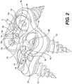
- FIG. 2 illustrates the plate assembly 10 with the bone screws 12a-12d and the blocking mechanisms 14a, 14b in an uninstalled state.
- the plate assembly 10 includes two pairs of bone screws 12a-12d, with each pair configured to be implanted into a vertebral body.
- the blocking mechanisms 14a, 14b each include a blocking screw 15a, 15b.
- the blocking screws 15a, 15b each include a head 16a, 16b with a varying circumferential edge 17a, 17b, and an engagement recess 20a, 20b configured to be engaged by a tool for rotationally driving the heads 16a, 16b.
- the geometry of the engagement recesses 20a, 20b can be varied.
- the engagement recess can be omitted and the blocking mechanisms 14a, 14b can be manually engaged/actuated by a user.
- the circumferential edges 17a, 17b of the blocking screws 15a, 15b include diametrically opposed cutouts 18a, 18b, and diametrically opposed lobes 19a, 19b.
- the cutouts 18a, 18b are dimensioned to allow passage of the bone screws 12a-12d when the cutouts 18a, 18b overlap an associated bone screw seat.
- the lobes 19a, 19b are configured to obstruct an associated bone screw seat to block the bone screws 12a-12d from backing out of the plate assembly 10.
- the engagement recesses 20a, 20b are illustrated with a hexagonal profile, but one of ordinary skill in the art would recognize from the present disclosure that any non-round profile can be used.
- the heads 16a, 16b are engaged by a user and rotated a quarter turn, i.e. 90 degrees, to move from a blocked position, in which bone screws 12a-12d are retained with the plate assembly, to an open position, in which the bone screws 12a-12d can be removed from the plate assembly 10.
- the blocked position corresponds to a position in which the bone screws seats are obstructed
- the open position corresponds to a position in which the bone screw seats are unobstructed.
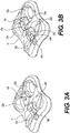
- Figure 3A illustrates an open configuration for the blocking mechanisms 14a, 14b
- Figure 3B illustrates a blocked configuration for the blocking mechanisms 14a, 14b
- the plate assembly 10 includes a base plate 11 that defines bone screw seats 22a-22d for a respective one of the bone screws 12a-12d.
- the plate 11 also defines blocking mechanism seats 24a, 24b, shown in Figure 3B , which are configured to retain a respective one of the blocking mechanisms 14a, 14b.
- the blocking mechanism seats 24a, 24b include a retention lip 25a, 25b that prevents the blocking mechanisms 14a, 14b from being removed from the plate 11.
- the blocking mechanisms 14a, 14b could be retained with the plate 11 by tabs, prongs, elastic elements, slots, channels, or other retention features.
- the blocking mechanisms 14a, 14b can include an enlarged head on an opposite end from the screw heads 16a, 16b and the plate 11 can define a retention recess dimensioned to captively secure the enlarged head of the blocking mechanisms 14a, 14b.
- retention features could be used, as long as the retention features retain the blocking mechanisms 14a, 14b with the base plate 11 while also allowing the blocking mechanisms 14a, 14b to rotate.
- Figures 4A and 4B illustrate the plate assembly 10 including a single bone screw 12b.
- Figure 4A illustrates the blocking mechanism 14a in an open position in which the bone screw 12b can be removed from the base plate 11.
- Figure 4B illustrates the blocking mechanism 14b in a blocking position in which the bone screw 12b is blocked from backing out of the plate assembly 10.
- Figures 5A-5E illustrate a base plate 211, and specifically illustrate the relatively high angulation of the bone screw seats 222a-222d.
- the base plate 211 includes a central window 209, which can be used by a surgeon during installation to view the disc space (and interbody implant). This window 209 can be used to assist in making sure the base plate 211 is the correct position. Although the window 209 is only illustrated in the embodiment of Figures 5A-5E , one of ordinary skill in the art would recognize from the present disclosure that the window 209 can be integrated into the design of any of the base plates disclosed herein.
- the plate 211 includes two blocking mechanisms 214a, 214b.
- the plate 211 defines channels 207a, 207b for each of the blocking mechanisms 214a, 214b in which blocking elements can slide.
- Blocking elements (not shown in Figure 5A ) are retained within the channels 207a, 207b and are driven outward to the bone screw seats 222a-222d to retain bone screws with the plate 211.
- a tapered profile defined by the channels 207a, 207b is shown in Figure 5D .
- the blocking elements of the blocking mechanism 214a, 214b have a complementary profile such that the blocking elements are retained in the channels 207a, 207b and can slide within the channels 207a, 207b.
- the channels 207a, 207b define a laterally outer stop surface for the blocking elements.
- the base plate 211 is divided by two primary axes: a central lateral axis X 1 and a central longitudinal axis X 2 .
- the high angulation of the bone screw seats 222a-222d provides a strong and rigid construction for attaching bone screws to a patient.
- the plate 211 allows bone screws to be inserted at high cephalad and caudal angles.
- the high angulation also allows for longer bone screws to be used for implantation, which corresponds to increased mechanical purchase and improved strength of the implantation.
- Each of the bone screw seats 222a-222d define a borehole 223a-223d with a central axis CA 1 -CA 4 .
- Each central axis CA 1 -CA 4 of boreholes 223a-223d is angled relative to the central lateral axis X 1 of the base plate 211 at a first angle ⁇ 1 .
- the first angle ⁇ 1 is between 50-75 degrees.
- the first angle ⁇ 1 is at least 65 degrees.
- the first angle ⁇ 1 is at least 70 degrees.
- Each central axis CA 1 -CA 4 of boreholes 223a-223d is also angled relative to the central longitudinal axis X 2 at a second angle ⁇ 2 .
- the second angle ⁇ 2 is between 4-8 degrees.
- the second angle ⁇ 2 is at least 6 degrees.
- Both the first angle ⁇ 1 and the second angle ⁇ 2 can be varied depending on the type of bone screw being used in a particular assembly.
- the threaded ends of bone screws inserted into bone screw seats 223a and 223b are angled or canted towards each other on an underside of the base plate 211 due to the second angle ⁇ 2 .
- the angulation of the central axes CA 1 -CA 4 of the boreholes 223a-223d for the bone screw seats 222a-222d are only specifically illustrated in Figures 5A-5E and explained with respect to these figures, one of ordinary skill in the art would understand that these angulation values are present for any of the other embodiments of the base plate described herein.
- FIGS 6A-6C illustrate another embodiment of a plate assembly 310 including a base plate 311.
- the plate assembly 310 includes two bone screw seats 322, with a single bone screw 312 arranged in one of the bone screw seats 322.
- This plate assembly 310 is only illustrated with two bone screw seats 322, but one of ordinary skill in the art would understand that the features of this embodiment can be adapted for a plate assembly including any number of bone screw seats.
- This plate assembly 310 is also illustrated as having a generic rectangular profile, however one of ordinary skill in the art would understand that the profile of the plate itself can vary, and can resemble the profile of the base plate 11 described above.
- the plate assembly 310 includes a blocking mechanism 314 having a different profile than the blocking mechanisms 14a, 14b of Figures 1-3B .
- the blocking mechanism 314 includes a head 316 with a varying circumferential edge 317, and an engagement recess 320 configured to engage a tool for rotationally driving the blocking mechanism 314.
- the edge 317 includes diametrically opposed cutouts 318, and diametrically opposed lobes 319.
- the cutouts 318 are dimensioned to allow insertion of the bone screw 312, and the lobes 319 are configured to block the bone screw 312 from backing out of the plate assembly 310.
- the lobes 319 are also configured to deflect inward when the bone screw is inserted and then blocks the bone screw from backing out.
- the circumferential edge 317 of the blocking mechanism 314 has a symmetrical profile such that the blocking mechanism 314 provides an identical profile if the blocking mechanism 314 is rotated 180°. Slots 321 are provided on the blocking mechanism 314 which provide grips or insertion points for a tool for rotating the blocking mechanism 314.
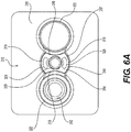
- Figure 6A illustrates the blocking mechanism 314 in an open position
- Figure 6B illustrates the blocking mechanism 314 in a blocked position without a bone screw 312.
- Figure 6C illustrates a side cross section view of the plate assembly 310.
- the plate 311 defines a blocking mechanism seat 324 which axially retains the blocking mechanism 314 within the plate 311.
- the plate 311 defines grooves 313 configured to engage a threading 323 defined on the blocking mechanism 314.
- a bone screw can be inserted into screw holes even when the blocking mechanism 314 is in a blocked position as shown in FIG. 6B , as the lobes of the blocking mechanism may be deformable.
- a clearance (c) is defined between the blocking mechanism 314 and the bone screw 312 when the bone screw 312 is fully seated in the bone screw seat 322.
- Figures 7A-7D illustrate another embodiment of a plate assembly 410 and a base plate 411.
- the blocking mechanism 414 includes a head 416 having a generally X-shaped profile, and including four arms 428.
- Resilient blocking elements 426 extend between a respective pair of the four arms 428 on diametrically opposed sides of the head 416.
- Reliefs 427 are provided on sides of the head 416 including the resilient blocking elements 426. These reliefs 427 allow for the resilient blocking elements 426 to deform radially inwardly towards a central rotational axis of the blocking mechanism 414.
- Figure 7A illustrates the blocking mechanism 414 in an open position.
- Figure 7B illustrates the blocking mechanism 414 is a blocked position, with the resilient blocking elements 426 overlapping the bone screw seats 422.
- This particular blocking mechanism 414 can be in either the open or blocked position and still allow insertion of the bone screw 412 into the plate assembly 410.
- This embodiment allows for the bone screw 412 to be inserted into the plate assembly 410 when the blocking mechanism 414 is in the blocked position ( Figure 7B ) due to elastic deformation of the resilient blocking elements 426 during insertion of the bone screw 412. Once fully inserted and installed, the bone screw 412 is prevented from backing out of the plate assembly 410 due to the resilient blocking elements 426.
- the resilient blocking element 426 is formed from spring steel. In another embodiment, the resilient blocking element 426 is formed from an elastomeric material.
- FIG. 7C illustrates the plate assembly 410 in a perspective view with the blocking mechanism 414 in a blocked position.
- the blocking mechanism 414 includes cutouts 418 that are dimensioned to allow passage of the bone screws 412.
- Figure 8 illustrates another embodiment of a plate assembly 510 in a blocked position.
- the plate assembly 510 includes a blocking mechanism 514 including blocking lobes 519.
- the blocking lobes 519 may have a rectangular profile.
- One of ordinary skill in the art would recognize from the present disclosure that the profile of the lobes can be modified.
- Figures 9A-9E illustrate another embodiment of a blocking mechanism 614.
- the blocking mechanism 614 of Figures 9A-9E can be integrated into any of the plate assemblies described herein.
- the blocking mechanism 614 includes a hub 650, a blocking element 654, and retention washer 658.
- the hub 650 defines grooves for accommodating the blocking element 654.
- the blocking element 654 defines lobes on diametrically opposite sides of the blocking element 654, each configured to block a bone screw within a cervical plate assembly.
- the blocking element 654 can be formed as a wire forming a continuous loop.
- the blocking element 654 can be snapped into or placed into the grooves formed on the hub 650, and a retention washer 658 can then be pressed or snapped onto a bottom end of the hub 650.
- the retention washer 658 can be snapped into a groove formed on the hub 650 such that the blocking element 654 is retained between the hub 650 and the retention washer 658.
- the blocking mechanism 614 can be rotated while retained within a seat of a base plate, such that the blocking element 654 moves from a position overlapping with a bone screw seat to block the bone screw seat, to an open position in which the blocking element 654 is rotated away from the bone screw seat and the bone screw seat is unobstructed.
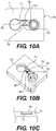
- FIGS 10A-10C illustrate another embodiment of a plate assembly 710.
- the plate assembly 710 includes a blocking mechanism 714 including blocking tabs 719 arranged on opposite sides of a central portion 729.
- the blocking tabs 719 are configured to provide obstructions to an underlying bone screw seat, such that a bone screw is retained with the plate assembly 710.
- the central portion 729 includes resilient arms 731, such that the blocking mechanism 714 can be deformed by applying inward pressure to the blocking tabs 719.
- the resilient arms 731 form an X-shaped configuration with reliefs 733 formed between the arms 731. A user can manually pinch the blocking tabs 719 towards each other, and the blocking mechanism 714 can be manipulated from an open position to a blocked position without the use of a tool.
- the blocking mechanism 714 can be retained with the base plate 711 via a slot 721 formed in the base plate 711, or other retention configuration. As shown in Figure 10C , the slot 721 has a tapered profile, and the blocking mechanism 714 has a complementary tapered profile such that the blocking mechanism 714 is retained within the slot 721.
- this slot 721 can be integrated into any of the base plates described herein to retain a blocking mechanism.
- Figures 11A and 11B illustrate another embodiment of a plate assembly 810 including a blocking mechanism 814.
- the blocking mechanism 814 includes a central hub 816 defining a pair of C-shaped arms 816a, 816b, with resilient blocking elements 826 extending therebetween. Blocking tabs 819 are engaged against a respective one of the resilient blocking elements 826. Reliefs 827 are formed on the hub 816, and the reliefs 827 are dimensioned to each accommodate one of the resilient blocking elements 826 and one of the blocking tabs 819.
- Figure 11A illustrates the blocking mechanism 814 in an expanded state in which the blocking tabs 819 are extended and configured to block a bone screw seat.
- the blocking mechanism 814 is configured to be rotated by 90° such that the blocking tabs 819 and the resilient blocking elements 826 are pushed inwardly into a respective one of the reliefs 827, and the blocking tabs 819 and the resilient blocking elements 826 are in a compressed state.
- the blocking tabs 819 can be retained within slots formed in the base plate 811, such that the blocking tabs 819 slide within the slots.
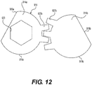
- FIG 12 illustrates an alternative configuration for a blocking mechanism 914 in which two blocking screws 914a, 914b are provided for blocking a respective bone screw seat.
- a single blocking screw 914a includes an engagement recess 920 configured to be engaged by a tool to rotate the blocking screw 914a.
- Each of the blocking screws 914a, 914b include teeth 937a, 937b which engage each other such that rotation of the first blocking screw 914a drives rotation of the second blocking screw 914b.
- the blocking screws 914a 914b each define a blocking lobe 919a, 919b and a cutout 918a, 918b such that in a blocked position the blocking lobes 919a, 919b overlap with a bone screw seat, and in an open position the cutouts 918a, 918b overlap with a bone screw seat to allow for insertion of a bone screw.
- Figure 13 illustrates a blocking mechanism 1014 that is directly integrated with a bone screw 1012.
- the bone screw 1012 is inserted into a base plate 1010, and the blocking mechanism 1014 provides axial retention of the bone screw 1012 relative to the base plate 1010.
- the blocking mechanism 1014 is formed as a split ring element, which is retained within a groove 1013 formed in a head of the bone screw 1012.
- a tool including a sleeve can be inserted around the head of the bone screw 1012 to push the blocking mechanism 1014 into the groove 1013 of the bone screw 1012.
- the blocking mechanism 1014 can define a tapered edge 1014' which is configured to engage against the base plate 1010 during insertion, such that the tapered edge 1014' slides along the base plate 1010 and the blocking mechanism 1014 is pushed into the groove 1013.
- Figures 14A-14D illustrate a blocking mechanism 1114 including two blocking elements 1114a, 1114b, a central resilient element 1126, and two blocking resilient elements 1126a, 1126b.
- the blocking resilient elements 1126a, 1126b are engaged against a base plate 1111, and retain the blocking elements 1114a, 1114b in a first position, which can correspond to an open configuration.
- the central resilient element 1126 biases the blocking elements 1114a, 1114b outward from each other, but the blocking resilient elements 1126a, 1126b define a stop against the base plate 1111 and prevent this outward movement in Figure 14A .
- FIG 14B shows a top view of the blocking mechanism 1114 with the blocking elements 1114a, 1114b in the blocked position and overlapping the bone screw seats 1122a, 1122b.
- Figure 14D illustrates the blocking mechanism 1114 separate from the base plate 1111.
- the blocking resilient elements 1126a, 1126b are pressed downward via a tool.
- the blocking resilient elements 1126a, 1126b can be pressed downward by a user/surgeon.
- the blocking resilient elements 1126a, 1126b are spring elements (e.g., leaf springs, cantilevered springs, etc.), but one of ordinary skill in the art would recognize from the present disclosure that alternative blocking elements can be used.
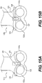
- Figures 15A and 15B illustrate another embodiment of a blocking mechanism 1214.
- the blocking mechanism 1214 includes a central blocking element 1219 that moves between a blocked position shown in Figure 15A and an open position in Figure 15B in which the bone screw seats 1222a, 1222b are either obstructed ( Figure 15A ) or unobstructed ( Figure 15B ).
- the central blocking element 1219 is a flexible plate that extends between lateral sides of the base plate 1211.
- a blocking cam 1226 is arranged within a slot 1221 formed on the base plate 1211.
- the blocking cam 1226 is configured to be positioned in a lower position within the slot 1221, as shown in Figure 15A , in which the central blocking element 1219 is flexed to overlap with the bone screw seats 1222a, 1222b.
- the terminal ends of the central blocking element 1219 are understood to be fixed to the lateral sides of the base plate 1211 such that the central blocking element 1219 flexes and exhibits inflexion as shown in Figure 15A .
- Figure 15B as the blocking cam 1226 is moved upward within the recess 1221, then the central blocking element 1219 returns to a relatively straight profile such that the central blocking element 1219 does not overlap with the bone screw seats 1222a, 1222b.
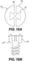
- Figures 16A and 16B illustrate an alternative embodiment of a bone screw 1312 including a screw head 1315.
- the screw head 1315 includes a slot 1316 and a relief 1317.
- the relief 1317 is centered relative to a shaft of the bone screw 1312.
- the relief 1317 acts as a drive feature to help thread the screw 1312 and allows the screw head 1315 to compress to reduce the outer diameter of the screw head 1315.
- the screw head 1315 provides an interference fit with the base plate when the driver tool is not engaged.
- Figures 17A-17C illustrate an alternative embodiment of a bone screw 1412.
- the bone screw 1412 has a screw head 1415 with a relief 1415'.
- the relief 1415' is configured to accommodate a portion of a blocking mechanism 1414 (shown in dashed lines in Figure 17A ).
- This relief 1415' allows for the blocking mechanism to partially overlap an axial end of the bone screw 1412, and as a result allows for a thinner base plate.
- the relief 1415' also ensures that the blocking mechanism sufficiently overlaps with the bone screw 1412 in the axial direction.
- FIGs 18A-18C illustrate another embodiment of a blocking mechanism 1514.
- the blocking mechanism 1514 includes a central biasing element 1526 and two blocking elements 1526a, 1526b on opposite ends of the central biasing element 1526.
- the blocking mechanism 1514 is retained to a base plate 1511, and the base plate 1511 includes bone screw seats 1522a, 1522b (a single bone screw 1512 is shown within the base plate 1511).
- the blocking elements 1526a, 1526b are in the extended position due to the biasing force from the biasing element 1526. In this position, the blocking elements 1526a, 1526b overlap with the bone screw seats 1522a, 1522b and are in a blocked position to retain the bone screws with the base plate 1511.
- the blocking elements 1526a, 1526b are in a compressed configuration with the biasing element 1526 being compressed and housed within cavities of the blocking elements 1526a, 1526b.
- the blocking elements 1526a, 1526b are positioned away from the bone screw seats 1522a 1522b such that the bone screw 1512 can be removed from the base plate 1511.
- the blocking elements 1526a, 1526b can be independently moved with respect to each other such that a bone screw 1512 can be removed from one of the bone screw seats 1522a, 1522b while a bone screw 1512 is blocked in the other one of the bone screw seats 1522a, 1522b.
- the central biasing element 1526 can be a coil spring, leaf spring, or any other type of elastic component.
- the blocking elements 1526a, 1526b are retained in the base plate 1511 via a mating slot feature.
- the base plate 1511 defines a slot 1517 with a protrusion 1517' and the blocking element 1526a includes a groove 1526a'.
- retention/mating features can be used to slidingly retain the blocking elements 1526a, 1526b with the base plate 1511.
- the retention can be achieved via a t-slot, dovetail, or other mating feature.
- the blocking elements 1526a, 1526b are slidingly retained within the slot 1517.
- a cover can be integrated into the base plate 1511 that covers the central biasing element 1526 to protect the central biasing element 1526.
- the blocking elements 1526a, 1526b define a housing cavity 1527 which is dimensioned to house a portion of the central biasing element 1526.
- the blocking mechanism 1514 is completely retained within the slot 1517 such that the blocking mechanism 1514 does not extend above an upper surface 1511a defined by the base plate 1511. This arrangement provides a lower profile for the plate assembly since the blocking mechanism 1514 does not add any additional height to the plate assembly.
- FIGS 19A-19C and Figure 20 illustrate another embodiment of a base plate 1911 having a blocking mechanism in accordance with embodiments of the present disclosure.
- the base plate 1911 is substantially similar to the base plate described above. As such, a description of similar features of the base plate 1911 will be omitted here.
- the blocking mechanism includes a blocking element 1926 (two blocking elements 1926a, 1926b shown) disposed in a corresponding groove 2125 (two grooves 2125a, 2125b) such that a portion of the blocking element protrudes into the bone screw seat 1922 (two bone screw seats 1922a, 1922b shown).
- the base plate 1911 may include four screw seats as discussed above with respect to bone plate 11 or up to twelve screw seats to accommodate more bone screws.
- the bone screw seat 1922 is substantially similar to the bone screw seats described above. As such, a description of the bone screw seat 1922 is omitted here.
- the blocking elements 1926a, 1926b are bias elements that move between an initial state (shown in Fig. 19A ) and a compressed state (shown in Figs. 19B and 19C ).
- the blocking elements 1926a, 1926b are spring elements. As shown in Figure 19A , the blocking elements 1926a, 1926b are in the initial state due to their intrinsic biasing force. In this position, the blocking elements 1926a, 1926b overlap with the bone screw seats 1922a, 1922b and are in a blocked position to retain the bone screws 2000 within the base plate 1911 (as shown in Figure 20 ).
- the blocking elements 1926a, 1926b are in a compressed configuration with the blocking elements 1926a, 1926b being compressed and entirely disposed within corresponding grooves 1925a, 1925b, which are formed in the base plate 1911 (shown more clearly in the cross-section of Figure 19C ) adjacent to corresponding screw seats 1922a, 1922b.
- the blocking elements 1926a, 1926b are positioned away from the bone screw seats 1922a 1922b such that the bone screw 2000 can be inserted or removed from the base plate 1911.
- the head of the bone screw contacts a ramped surface 1924 of the corresponding blocking element 1926 to deflect the blocking element 1926 away from the screw seat 1922 as the screw 2000 continues to be advanced.
- the blocking element 1926 returns to its initial state, thus blocking removal of the screw 2000 from the screw seat 1922 (as shown in Fig. 20 ).
- the blocking element 1926 resists screw back out by partially protruding into the screw seat 1922 and contacting a portion of the screw head.
- the blocking element 1926 advantageously provides tactile feedback to the surgeon so that there is confirmation that the blocking element 1926 has returned to its initial position to block the screw 2000.
- the blocking element 1926 also advantageously provides visual confirmation to the surgeon that the blocking element 1926 is being deflected away from the screw seat 1922 during insertion and that the blocking element 1926 has returned to its initial state after the screw 2000 has passes beneath the blocking element 1926.
- the blocking element 1926 must first be compressed (i.e., moved away from the screw seat 1922). This may be performed using a driver (not shown) having a taper that compresses the blocking element 1926 as the drive tip is inserted into the screw head. Alternatively, there may be a separate instrument that can compress the blocking element 1926 so that a driver can be inserted into the screw head to remove it.
- the blocking elements 1926a, 1926b can be independently moved with respect to each other such that a bone screw 2000 can be inserted or removed from one of the bone screw seats 1922a, 1922b while a bone screw is blocked in the other one of the bone screw seats 1922a, 1922b.
- a bone screw 2000 can be inserted or removed from one of the bone screw seats 1922a, 1922b while a bone screw is blocked in the other one of the bone screw seats 1922a, 1922b.
- One of ordinary skill in the art would recognize from the present disclosure that alternative types of blocking elements that elastically deform to retain a screw within the base plate 1911 are within the scope of the present disclosure.
- the retention can be achieved via a t-slot, dovetail, or other mating feature.
- the base plate 1911 may include a through hole 1940 disposed between two screw seats 1922 and at a midline of the base plate 1911.
- the through hole 1940 facilitates the insertion of temporary fixation elements (not shown) through the hole 1940 and into a bone (e.g., a vertebra) onto which the plate 1911 is to be coupled to preliminarily capture the plate 1911 onto the bone.
- the base plate 1911 may additionally include one or more cuts 1942 formed an outer surface 1944 of the base plate 1911 to allow a tool (not shown) to grasp the base plate 1911 in the predetermined orientation and insert the plate in the predetermined trajectory.
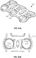
- Figures 21A-21D illustrate another embodiment of a base plate 2111 having blocking elements 2126 disposed corresponding screw seats 2122 in accordance with embodiments of the present disclosure.
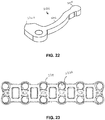
- Figure 22 illustrates a blocking element 2126.
- the base plate 2111 is substantially similar to the base plate 1911 described above. As such, a description of similar features of the base plate 2111 will be omitted here.
- the base plate 2111 is illustrated as having six screw seats 2122, each having a corresponding blocking element 2126, it should be noted that the base plate 2126 may alternatively have fewer (two or four as with the base plates discussed above) or more (up to twelve) screw seats 2122.
- the blocking element 2126 may alternatively be planar instead of having a ramped surface.
- a bone screw e.g., screw 2000
- the bottom ramped surface of the screw head contacts an innermost tip 2132 of the blocking element 2126 and moves it towards the compressed state (shown in Figures 21C, 21D ) as the screw is advanced further through the screw seat 2122.
- the blocking element 2126 returns to its initial state (illustrated in Figure 21A, 21B ) after the screw head passes beneath the blocking element 2126 to obstruct the screw seat 2122 and retain the screw within the screw seat 2122.
- the blocking element 2126 is a monolithic planar element having a blocking portion 2202, a base portion 2204, and an arm 2206 coupling the blocking portion 2202 to the base portion 2204.
- the base portion 2204 has a bulbous shape and is retained in a correspondingly shaped opening 2208 formed in the base plate 2111 (shown more clearly in the cross-section of Figure 21D ).
- the blocking element 2126 is compressed by the screw head, the blocking portion 2202 is pushed into a groove 2125 formed in the base plate 2111 such that the screw seat 2122 is unobstructed.
- the above-disclosed base plates may utilize a variety of different fixation elements to secure the base plate to a vertebra such as, for example, fixed angle screws, variable angle screws, self-drilling tip screws, self-tapping tip screws, primary diameter screws, rescue diameter screws, and double rescue diameter screws.
- Figures 24A-24B, 25A-25B , 27, and 28 depict examples of fixation elements (e.g., screws) for use with the base plates (e.g. base plates 11, 1911, 1511, 2111) in accordance with embodiments of the present disclosure.
- Figures 26A-26B depict a cervical plate assembly with the screws of Figures 24A-25B in accordance with embodiments of the present disclosure.
- each screw consists of a spherical screw head with a drive feature used to thread the screw into the bone. This spherical screw head sits in a corresponding spherical hole in the base plate, which provides the capability of polyaxial motion of the screw.
- the fixed angle screw has a larger neck diameter which allows for less angulation in the plate compared to the variable angle screw. Such a scenario may be beneficial when, for example, a surgeon wants to limit post-operative settling.
- the variable angle screw has a smaller neck diameter which allows for more angulation of the screw in the plate.
- different types of fixation elements may include identifying features to clearly distinguish them from one another. For example, as will be discussed below, screw heads may include a predetermined pattern of cuts and laser marks to distinguish the various types of fixation elements (i.e., screws) from one another.
- Figures 24A-24B depict a fixed angle screw 2400.
- the screw 2400 includes a head 2402, a threaded shaft 2404 extending from the head 2402, and a neck portion 2406 disposed between the head 2402 and the threaded shaft 2404.
- the screw head 2402 includes a tool engagement feature 2408 so that driver (not shown) can engage the screw 2400 and drive it into a bone.
- the screw head 2402 further includes identifying features 2410. In some embodiments, the identifying features 2410 may be cutouts filled with laser marks and arranged in a predetermined configuration to identify the screw 2400 as a fixed angle screw.
- Figures 25A-25B depict a variable angle screw 2500.
- the screw 2500 includes a head 2502, a threaded shaft 2504 extending from the head 2502, and a neck portion 2506 disposed between the head 2502 and the threaded shaft 2504.
- the screw head 2502 includes a tool engagement feature 2508 so that driver (not shown) can engage the screw 2500 and drive it into a bone.
- the screw head 2502 further includes identifying features 2510. In some embodiments, the identifying features 2510 may be cutouts filled with laser marks and arranged in a predetermined configuration to identify the screw 2500 as a variable angle screw.
- the base plates of the present disclosure may include various different fixation elements.
- the base plate may include the fixed angle screw 2400 disposed in one screw seat and the variable angle screw 2500 disposed in a different screw seat.
- Figure 26B is a top view of the variable angle screw 2500 disposed in its screw seat with the blocking element disposed above the screw head to prevent any possible backing out of the screw.
- Figures 27 and 28 depict additional examples of different fixation elements that may be used with the base plates of the present disclosure.
- Figure 27 depicts a screw 2700 having a self-drilling tip 2702.
- Figure 28 depicts a screw having a self-tapping tip 2802.
- the self-drilling tip 2702 is sharp, which allows a user to insert the screw 2700 without drilling a pilot hole in the bone.
- the self-tapping tip 2802 is blunt, which requires a user to pre-drill pilot hole prior to inserting the screw 2800.
- the screws may also include a cut 2704, 2804 on the top of the screw head to allow for additional clearance blocking element. This advantageously helps block the screw disposed in the screw seat by keeping the screw head contact surface farther away from the blocking element.
- the removal tool 2900 includes a driver 2902 extending through a removal sleeve 2904.
- the driver 2902 extends from a proximal end 2906 having a coupling portion 2908 to a distal end 2910 having a driver tip 2912.
- the coupling portion 2908 is configured to be coupled to a handle (not shown) or a power tool (e.g., a drill) for rotation of the driver 2902.
- the driver tip 2912 is configured to engage a tool engagement feature (e.g., 2408, 2508) in a screw (e.g., 2000, 2400, 2500, 2700, 2800, etc.) and may have any shape that corresponds to the tool engagement feature (e.g., hexalobular, hexagonal, cross, etc.)
- the driver tip 2912 is a self-retaining tip configured to retain the screw thereon.
- the removal sleeve 2904 extends from a proximal end 2914 to a distal end 2916.
- the removal sleeve 2904 includes a hollow interior having an internal diameter large enough to allow the driver 2902 to be inserted therethrough.
- the removal sleeve includes a reduced diameter section 2905 extending a predetermined length L 1 from the proximal end 2914 and terminating between the proximal and distal ends 2914, 2916.
- the reduced diameter section 2905 has an inner diameter that is smaller than the inner diameter of the rest of the removal sleeve 2904 but still larger than the diameter of the driver 2902.
- the reduced diameter section 2905 facilitates frictional sliding between removal sleeve 2904 and the driver 2902 such that the removal sleeve 2904 does not easily slide along the driver 2902 in an uncontrolled manner.
- the proximal end 2914 may include a plurality of prongs 2907 (two shown) separated by a corresponding plurality of slots 2909 (one shown). The plurality of prongs 2907 and slots 2909 allow the proximal end 2914 to flex radially outwardly as the removal sleeve is slid onto the driver 2902 to facilitate an easier insertion of the driver 2902 into the sleeve 2904.
- the distal portion 2916 includes a prong 2918 configured to engage the blocking element 2126 when the removal sleeve is inserted into a bone screw seat 1922 and rotated.
- the prong 2918 does not extend the entire circumference of the removal sleeve 2904 so that when the prong 2918 is first inserted into the bone screw seat 2122, it is spaced apart from the blocking element 2126 and only when the sleeve 2904 is rotated does the prong 2918 engage the blocking element 2126.
- the distal portion 2914 tapers radially inwardly towards the prong 2918.
- the removal sleeve 2904 may include a textured surface proximate the proximate end to enhance gripping of the removal sleeve 2904 while it is rotated to engage the blocking element 2126.
- Figures 30A and 30B depict the removal tool 2900 in use with a cervical plate assembly in accordance with embodiments of the present disclosure.
- Figure 30A depicts the insertion of the driver tip 2912 into the tool engagement feature (e.g., 2508) of a screw (e.g., 2500) which has already been inserted into the screw seat 2122 and blocked off by the blocking element 2126.
- the removal sleeve 2904 is rotated so that the prong 2918 forces the blocking element 2126 away from the screw head such that that it does not block the screw head.
- the removal sleeve 2904 may be rotated in either direction (as indicated by arrow A) to push the blocking element 2126 back into its groove.
- the removal sleeve 2904 is left in place (as shown in Figure 30B ) and the driver 2902 may be rotated to remove the screw from the screw seat 2122. Finally, the removal tool 2900 is removed along with the screw.
Landscapes
- Health & Medical Sciences (AREA)
- Orthopedic Medicine & Surgery (AREA)
- Surgery (AREA)
- Life Sciences & Earth Sciences (AREA)
- Heart & Thoracic Surgery (AREA)
- Nuclear Medicine, Radiotherapy & Molecular Imaging (AREA)
- Engineering & Computer Science (AREA)
- Biomedical Technology (AREA)
- Neurology (AREA)
- Medical Informatics (AREA)
- Molecular Biology (AREA)
- Animal Behavior & Ethology (AREA)
- General Health & Medical Sciences (AREA)
- Public Health (AREA)
- Veterinary Medicine (AREA)
- Surgical Instruments (AREA)
Abstract
A cervical plate assembly is disclosed. The cervical plate assembly includes a base plate including: (1) at least two bone screw seats, each bone screw seat including a borehole dimensioned to receive a bone screw, and (2) a first blocking seat positioned between the at least two bone screw seats. The cervical plate assembly includes a blocking mechanism retained within the first blocking seat of the base plate. The blocking mechanism is selectively positionable between a closed position in which the blocking mechanism obstructs at least one bone screw seat to retain a bone screw with the base plate, and an open position in which the bone screw seats are unobstructed.
Description
- The present application is a continuation-in-part of
U.S. 16/407,284, filed May 9, 2019 U.S. 16/356,760, filed March 18, 2019 U.S. 15/814,490, filed November 16, 2017 - The present disclosure is related to a surgical implant, and is more particularly related to an anterior cervical plate.
- Certain surgical procedures require a surgeon to fuse portions of a patient's spine to each other. Implanting a cervical plate reduces a patient's range of motion, and helps relieve pain experienced by a patient. Although cervical plate implantations are used to treat radiculopathy or myelopathy, but one of ordinary skill in the art would recognize that fusion can be used for other types of surgery.
- Anterior cervical plate assemblies typically include a base plate defining through openings for bone screws to anchor the base plate to a patient's spine. Some cervical plate assemblies include a blocking mechanism to prevent the bone screws from inadvertently backing out of the base plate. One type of known blocking mechanism includes an automated blocking feature, such that once a bone screw passes a predetermined threshold then the blocking mechanism is automatically activated to block the bone screws from inadvertently backing out of the plate. These automated blocking mechanisms can be complicated for surgeons to operate, and can make removal of the base plate difficult.
- Other known blocking mechanisms for anterior cervical plate assemblies rely on a patient's bones to have a certain strength characteristic to withstand the blocking mechanism features. Some known types of blocking mechanisms require force for removing a screw from the blocking mechanism. However, this type of blocking mechanism can cause stripping of the screw holes for bone screws implanted in a patient's bones.
- Another known type of blocking mechanism for anterior cervical plate assemblies requires additional steps to install and lock the blocking mechanism screw in the plate. In some devices, this additional step requires a specialty tool or instrument. These steps are time consuming and require the surgeon to perform additional steps during surgery, which is undesirable.
- It would be desirable to provide an improved cervical plate assembly that is relatively simple to use and provides a reliable blocking function.
- Briefly stated, an improved cervical plate assembly is disclosed. The cervical plate assembly includes a base plate including four bone screw seats. Each bone screw seat includes a borehole dimensioned to receive a bone screw. Each borehole defines a central axis that is (a) angled relative to a central lateral axis of the base plate at a first angle and (b) angled relative to a central longitudinal axis at a second angle. In one embodiment, the first angle is at least 25 degrees, and the second angle is at least 6 degrees. The base plate defines two retention slots that are each positioned between a pair of the four bone screw seats. The assembly includes two blocking mechanisms. Each blocking mechanism includes a biasing element arranged between a first blocking element and a second blocking element. The first blocking element is configured to obstruct a first bone screw seat of the four bone screw seats, and the second blocking element is configured to obstruct a second bone screw seat of the four bone screw seats. The first blocking element and the second blocking element are independently positionable from each other. Each blocking mechanism is retained within a respective one of the two retention slots. The blocking mechanisms are selectively positionable between a closed position in which the blocking mechanism obstructs at least one bone screw seat to retain a bone screw with the base plate, and an open position in which the bone screw seats are unobstructed.
- A variety of arrangements and embodiments are described in more detail below and in the claims.
- The foregoing summary as well as the following detailed description will be best understood when read in conjunction with the appended drawings. In the drawings:
-
Figure 1 is a perspective view of one embodiment of a cervical plate assembly implanted on a patient's spine. -
Figure 2 is a perspective view of the cervical plate assembly ofFigure 1 including bone screws. -
Figure 3A is a perspective view of the cervical plate assembly ofFigures 1 and2 with a blocking mechanism in an open position. -
Figure 3B is a perspective view of the cervical plate assembly ofFigures 1-3A with the blocking mechanism in a blocked position. -
Figure 4A is a top perspective view of the cervical plate assembly ofFigures 1-3B including an installed bone screw with the blocking mechanism in the open position. -
Figure 4B is a top perspective view of the cervical plate assembly ofFigures 1-4A including an installed bone screw with the blocking mechanism in the blocked position. -
Figure 5A is a top view of a cervical plate assembly according to one embodiment. -
Figure 5B is a side view of the cervical plate assembly ofFigure 5A . -
Figure 5C is a front view of the cervical plate assembly ofFigures 5A and 5B . -
Figure 5D is a cross-sectional view alongline 5D-5D ofFigure 5C . -
Figure 5E is a cross-sectional view alongline 5E-5E ofFigure 5B . -
Figure 6A is a top view of a cervical plate assembly in an open position according to one embodiment. -
Figure 6B is a top view of the cervical plate assembly ofFigure 6A in a blocked position. -
Figure 6C is a side cross sectional view of the cervical plate assembly ofFigures 6A and6B including a bone screw in a blocked position. -
Figure 7A is a top view of a cervical plate assembly in an open position according to one embodiment. -
Figure 7B is a top view of the cervical plate assembly ofFigure 7A in a blocked position. -
Figure 7C is a perspective view of the cervical plate assembly ofFigures 7A and7B in the blocked position. -
Figure 7D is a cross section view of a blocking mechanism of the cervical plate assembly ofFigures 7A-7C . -
Figure 8 is a perspective view of a cervical plate assembly in a blocked position according to one embodiment. -
Figure 9A is a top view of a blocking mechanism according to one embodiment. -
Figure 9B is a perspective view of the blocking mechanism ofFigure 9A . -
Figures 9C-9E are perspective views of sub-components of the blocking mechanism of -
Figures 9A and 9B . -
Figure 10A is a top view of a cervical plate assembly including a bone screw in a blocked position according to one embodiment. -
Figure 10B is a perspective view of the cervical plate assembly ofFigure 10A . -
Figure 10C is a side cross section view of the base plate ofFigures 10A and 10B . -
Figure 11A is a top view of an embodiment of a cervical plate assembly. -
Figure 11B is a side view of the cervical plate assembly ofFigure 11A . -
Figure 12 is a top view of an embodiment of a blocking mechanism. -
Figure 13 is a side view of an embodiment of a blocking mechanism associated with a bone screw. -
Figure 14A is a side view of a blocking mechanism according to one embodiment in an open position. -
Figure 14B is a side view of the blocking mechanism ofFigure 14A in a blocked position. -
Figure 14C is a top view of the blocking mechanism ofFigures 14A and 14B . -
Figure 14D is a side view of a portion of the blocking mechanism ofFigures 14A-14C . -
Figure 15A is a top view of a blocking mechanism according to one embodiment in a blocked position. -
Figure 15B is a top view of the blocking mechanism ofFigure 15A in an open positon. -
Figure 16A is a top view of a blocking mechanism according to one embodiment. -
Figure 16B is a side cross section view of the blocking mechanism ofFigure 16A . -
Figure 17A is a magnified, side view a bone screw according to one embodiment. -
Figure 17B is a side view of the bone screw ofFigure 17A . -
Figure 17C is a cross section view of the bone screw ofFigure 17B alongline 17C-17C. -
Figure 18A is a top view of a cervical plate assembly in a blocked position according to one embodiment. -
Figure 18B is a top view of the cervical plate assembly ofFigure 18A in an open position. -
Figure 18C is a side cross section view of a blocking mechanism for the cervical plate assembly ofFigures 18A and 18B . -
Figure 19A is a top view of a cervical plate assembly having a blocking mechanism in a blocked position according to one embodiment. -
Figure 19B is a top view of the cervical plate assembly ofFigure 18A in an open position. -
Figure 19C is a top cross section view of the cervical plate assembly illustrated inFigure 19B . -
Figure 20 is a top view of the cervical plate assembly ofFigures 19A-19C with a fixation element extending therethrough. -
Figure 21A is a perspective view of a cervical plate assembly according to one embodiment. -
Figure 21B is a top view of the cervical plate assembly ofFigure 21A having a blocking mechanism in a blocked position. -
Figure 21C is a top view of the cervical plate assembly ofFigure 21A having a blocking mechanism in an open position. -
Figure 21D is a top cross section view of the cervical plate assembly illustrated inFigure 21C . -
Figure 22 is a perspective view of a blocking element in accordance with embodiments of the present disclosure. -
Figure 23 is a top view of a cervical plate assembly according to one embodiment. -
Figures 24A-24B depict an example of a fixation element for use with a cervical plate assembly in accordance with embodiments of the present disclosure. -
Figures 25A-25B depict an example of a fixation element for use with a cervical plate assembly in accordance with embodiments of the present disclosure. -
Figures 26A-26B depict a cervical plate assembly with the screws ofFigures 24A-25B in accordance with embodiments of the present disclosure. -
Figure 27 depicts an example of a fixation element for use with a cervical plate assembly in accordance with embodiments of the present disclosure. -
Figure 28 depicts an example of a fixation element for use with a cervical plate assembly in accordance with embodiments of the present disclosure. -
Figures 29A and 29B depict side views of a removal tool in an assembled and disassembled state in accordance with embodiments of the present disclosure. -
Figures 30A and30B depict a removal tool in use with a cervical plate assembly in accordance with embodiments of the present disclosure. - It is to be understood that the present disclosure is not limited in its application to the details of construction and the arrangement of components set forth in the description herein or illustrated in the drawings. The teachings of the present disclosure may be used and practiced in other embodiments and practiced or carried out in various ways. Also, it is to be understood that the phraseology and terminology used herein is for the purpose of description and should not be regarded as limiting. The use of "including," "comprising," or "having" and variations thereof herein is meant to encompass the items listed thereafter and equivalents thereof as well as additional items. Unless specified or limited otherwise, the terms "mounted," "connected," "supported," and "coupled" and variations thereof are used broadly and encompass both direct and indirect mountings, connections, supports, and couplings. Further, "connected" and "coupled" are not restricted to physical or mechanical connections or couplings.
- The following discussion is presented to enable a person skilled in the art to make and use embodiments of the present disclosure. Various modifications to the illustrated embodiments will be readily apparent to those skilled in the art, and the principles herein can be applied to other embodiments and applications without departing from embodiments of the present disclosure. Thus, the embodiments are not intended to be limited to embodiments shown, but are to be given the widest scope consistent with the principles and features disclosed herein. The following detailed description is to be read with reference to the figures, in which like elements in different figures have like reference numerals. The figures, which are not necessarily to scale, depict selected embodiments and are not intended to limit the scope of the embodiments. Skilled artisans will recognize the examples provided herein have many useful alternatives and fall within the scope of the embodiments.
-
Figure 1 illustrates a cervical region of a patient's spine 1 with an anteriorcervical plate assembly 10 implanted on the spine 1. As shown inFigure 1 , theplate assembly 10 is implanted at the C4-C5 vertebrae of the spine 1. One of ordinary skill in the art would recognize that theplate assembly 10 could be installed at different regions of the patient's spine 1. The term plate assembly is generically used herein to generally refer to the plate assemblies described in some of the embodiments. In one embodiment, the plate assemblies are specifically designed to be used for anterior cervical implantations. One of ordinary skill in the art would understand from the present disclosure that the concepts and features of the plate assemblies disclosed herein could be adapted for surgical assemblies and techniques for other portions of a user's anatomy besides the spine. With respect toFigure 1 , the anteriorcervical plate assembly 10 is shown including fourbone screws 12a-12d and twoblocking assemblies cervical plate assembly 10 could be used. For instance, the cervical plate assembly can extend to multiple levels of the spine and include additional screw holes for additional fixation to adjacent vertebral bodies. The bone screws used in any of the embodiments described herein can be self-drilling, self-tapping, variable angle, fixed angle, or any other known type of bone screw design. Additionally, the embodiments of the base plate described herein can be configured to accept bone screws having screw diameters of 4.2 mm and 4.6 mm, although one of ordinary skill in the art would understand that different sizes for bone screws can be used.Figure 2 illustrates theplate assembly 10 with the bone screws 12a-12d and the blockingmechanisms Figure 2 , theplate assembly 10 includes two pairs ofbone screws 12a-12d, with each pair configured to be implanted into a vertebral body. In this embodiment, the blockingmechanisms screw 15a, 15b. The blocking screws 15a, 15b each include ahead circumferential edge engagement recess heads mechanisms - As shown in
Figure 2 , thecircumferential edges screws 15a, 15b include diametricallyopposed cutouts opposed lobes cutouts cutouts lobes plate assembly 10. The engagement recesses 20a, 20b are illustrated with a hexagonal profile, but one of ordinary skill in the art would recognize from the present disclosure that any non-round profile can be used. Theheads plate assembly 10. As used herein, the blocked position corresponds to a position in which the bone screws seats are obstructed and the open position corresponds to a position in which the bone screw seats are unobstructed. -
Figure 3A illustrates an open configuration for the blockingmechanisms Figure 3B illustrates a blocked configuration for the blockingmechanisms Figures 3A and 3B , theplate assembly 10 includes abase plate 11 that definesbone screw seats 22a-22d for a respective one of the bone screws 12a-12d. Theplate 11 also defines blockingmechanism seats Figure 3B , which are configured to retain a respective one of the blockingmechanisms blocking mechanism seats retention lip mechanisms plate 11. One of ordinary skill in the art would recognize from the present disclosure that alternative retention arrangements could be provided for ensuring the blockingmechanisms plate 11. For example, the blockingmechanisms plate 11 by tabs, prongs, elastic elements, slots, channels, or other retention features. In one embodiment, the blockingmechanisms plate 11 can define a retention recess dimensioned to captively secure the enlarged head of the blockingmechanisms mechanisms base plate 11 while also allowing the blockingmechanisms -
Figures 4A and 4B illustrate theplate assembly 10 including asingle bone screw 12b.Figure 4A illustrates theblocking mechanism 14a in an open position in which thebone screw 12b can be removed from thebase plate 11.Figure 4B illustrates theblocking mechanism 14b in a blocking position in which thebone screw 12b is blocked from backing out of theplate assembly 10. -
Figures 5A-5E illustrate abase plate 211, and specifically illustrate the relatively high angulation of thebone screw seats 222a-222d. Thebase plate 211 includes acentral window 209, which can be used by a surgeon during installation to view the disc space (and interbody implant). Thiswindow 209 can be used to assist in making sure thebase plate 211 is the correct position. Although thewindow 209 is only illustrated in the embodiment ofFigures 5A-5E , one of ordinary skill in the art would recognize from the present disclosure that thewindow 209 can be integrated into the design of any of the base plates disclosed herein. Theplate 211 includes two blockingmechanisms Figure 5A , theplate 211 defineschannels mechanisms Figure 5A ) are retained within thechannels bone screw seats 222a-222d to retain bone screws with theplate 211. A tapered profile defined by thechannels Figure 5D . The blocking elements of theblocking mechanism channels channels channels - As shown in
Figure 5A , thebase plate 211 is divided by two primary axes: a central lateral axis X1 and a central longitudinal axis X2. The high angulation of thebone screw seats 222a-222d provides a strong and rigid construction for attaching bone screws to a patient. Theplate 211 allows bone screws to be inserted at high cephalad and caudal angles. The high angulation also allows for longer bone screws to be used for implantation, which corresponds to increased mechanical purchase and improved strength of the implantation. Each of thebone screw seats 222a-222d define a borehole 223a-223d with a central axis CA1-CA4. Each central axis CA1-CA4 ofboreholes 223a-223d is angled relative to the central lateral axis X1 of thebase plate 211 at a first angle θ1. In one embodiment, the first angle θ1 is between 50-75 degrees. In one embodiment, the first angle θ1 is at least 65 degrees. In one embodiment, the first angle θ1 is at least 70 degrees. Each central axis CA1-CA4 ofboreholes 223a-223d is also angled relative to the central longitudinal axis X2 at a second angle θ2. In one embodiment, the second angle θ2 is between 4-8 degrees. In one embodiment, the second angle θ2 is at least 6 degrees. Both the first angle θ1 and the second angle θ2 can be varied depending on the type of bone screw being used in a particular assembly. During installation, the threaded ends of bone screws inserted intobone screw seats Figure 5A ) are angled or canted towards each other on an underside of thebase plate 211 due to the second angle θ2. Although the angulation of the central axes CA1-CA4 of theboreholes 223a-223d for thebone screw seats 222a-222d are only specifically illustrated inFigures 5A-5E and explained with respect to these figures, one of ordinary skill in the art would understand that these angulation values are present for any of the other embodiments of the base plate described herein. -
Figures 6A-6C illustrate another embodiment of aplate assembly 310 including abase plate 311. As shown inFigures 6A-6C theplate assembly 310 includes two bone screw seats 322, with asingle bone screw 312 arranged in one of the bone screw seats 322. Thisplate assembly 310 is only illustrated with two bone screw seats 322, but one of ordinary skill in the art would understand that the features of this embodiment can be adapted for a plate assembly including any number of bone screw seats. Thisplate assembly 310 is also illustrated as having a generic rectangular profile, however one of ordinary skill in the art would understand that the profile of the plate itself can vary, and can resemble the profile of thebase plate 11 described above. - The
plate assembly 310 includes ablocking mechanism 314 having a different profile than the blockingmechanisms Figures 1-3B . Theblocking mechanism 314 includes ahead 316 with a varyingcircumferential edge 317, and anengagement recess 320 configured to engage a tool for rotationally driving theblocking mechanism 314. Theedge 317 includes diametricallyopposed cutouts 318, and diametricallyopposed lobes 319. Thecutouts 318 are dimensioned to allow insertion of thebone screw 312, and thelobes 319 are configured to block thebone screw 312 from backing out of theplate assembly 310. Thelobes 319 are also configured to deflect inward when the bone screw is inserted and then blocks the bone screw from backing out. Thecircumferential edge 317 of theblocking mechanism 314 has a symmetrical profile such that theblocking mechanism 314 provides an identical profile if theblocking mechanism 314 is rotated 180°.Slots 321 are provided on theblocking mechanism 314 which provide grips or insertion points for a tool for rotating theblocking mechanism 314.Figure 6A illustrates theblocking mechanism 314 in an open position, andFigure 6B illustrates theblocking mechanism 314 in a blocked position without abone screw 312.Figure 6C illustrates a side cross section view of theplate assembly 310. As shown inFigure 6C , theplate 311 defines ablocking mechanism seat 324 which axially retains theblocking mechanism 314 within theplate 311. Theplate 311 definesgrooves 313 configured to engage a threading 323 defined on theblocking mechanism 314. It should be noted that, a bone screw can be inserted into screw holes even when theblocking mechanism 314 is in a blocked position as shown inFIG. 6B , as the lobes of the blocking mechanism may be deformable. As shown inFigure 6C , a clearance (c) is defined between theblocking mechanism 314 and thebone screw 312 when thebone screw 312 is fully seated in thebone screw seat 322. Although the clearance (c) is only illustrated with respect to this embodiment, one of ordinary skill in the art would recognize that the clearance can be provided in any of the other embodiments described herein. -
Figures 7A-7D illustrate another embodiment of aplate assembly 410 and abase plate 411. Theblocking mechanism 414 includes ahead 416 having a generally X-shaped profile, and including fourarms 428.Resilient blocking elements 426 extend between a respective pair of the fourarms 428 on diametrically opposed sides of thehead 416.Reliefs 427 are provided on sides of thehead 416 including theresilient blocking elements 426. Thesereliefs 427 allow for theresilient blocking elements 426 to deform radially inwardly towards a central rotational axis of theblocking mechanism 414.Figure 7A illustrates theblocking mechanism 414 in an open position.Figure 7B illustrates theblocking mechanism 414 is a blocked position, with theresilient blocking elements 426 overlapping the bone screw seats 422. Thisparticular blocking mechanism 414 can be in either the open or blocked position and still allow insertion of thebone screw 412 into theplate assembly 410. This embodiment allows for thebone screw 412 to be inserted into theplate assembly 410 when theblocking mechanism 414 is in the blocked position (Figure 7B ) due to elastic deformation of theresilient blocking elements 426 during insertion of thebone screw 412. Once fully inserted and installed, thebone screw 412 is prevented from backing out of theplate assembly 410 due to theresilient blocking elements 426. In one embodiment, theresilient blocking element 426 is formed from spring steel. In another embodiment, theresilient blocking element 426 is formed from an elastomeric material. One of ordinary skill in the art would recognize from the present disclosure that alternative types of blockingelements 426 can be used as long as the blockingelements 426 are configured to elastically deform during insertion of the bone screws and return to an initial position after insertion that blocks or overlaps with the inserted bone screw.Figure 7C illustrates theplate assembly 410 in a perspective view with theblocking mechanism 414 in a blocked position. As shown more clearly inFigure 7D , theblocking mechanism 414 includescutouts 418 that are dimensioned to allow passage of the bone screws 412. -
Figure 8 illustrates another embodiment of aplate assembly 510 in a blocked position. Theplate assembly 510 includes ablocking mechanism 514 including blockinglobes 519. The blockinglobes 519 may have a rectangular profile. One of ordinary skill in the art would recognize from the present disclosure that the profile of the lobes can be modified. -
Figures 9A-9E illustrate another embodiment of ablocking mechanism 614. Theblocking mechanism 614 ofFigures 9A-9E can be integrated into any of the plate assemblies described herein. Theblocking mechanism 614 includes ahub 650, a blockingelement 654, andretention washer 658. Thehub 650 defines grooves for accommodating theblocking element 654. The blockingelement 654 defines lobes on diametrically opposite sides of the blockingelement 654, each configured to block a bone screw within a cervical plate assembly. The blockingelement 654 can be formed as a wire forming a continuous loop. The blockingelement 654 can be snapped into or placed into the grooves formed on thehub 650, and aretention washer 658 can then be pressed or snapped onto a bottom end of thehub 650. Theretention washer 658 can be snapped into a groove formed on thehub 650 such that the blockingelement 654 is retained between thehub 650 and theretention washer 658. Theblocking mechanism 614 can be rotated while retained within a seat of a base plate, such that the blockingelement 654 moves from a position overlapping with a bone screw seat to block the bone screw seat, to an open position in which theblocking element 654 is rotated away from the bone screw seat and the bone screw seat is unobstructed. -
Figures 10A-10C illustrate another embodiment of aplate assembly 710. Theplate assembly 710 includes ablocking mechanism 714 including blockingtabs 719 arranged on opposite sides of acentral portion 729. The blockingtabs 719 are configured to provide obstructions to an underlying bone screw seat, such that a bone screw is retained with theplate assembly 710. Thecentral portion 729 includesresilient arms 731, such that theblocking mechanism 714 can be deformed by applying inward pressure to the blockingtabs 719. Theresilient arms 731 form an X-shaped configuration withreliefs 733 formed between thearms 731. A user can manually pinch the blockingtabs 719 towards each other, and theblocking mechanism 714 can be manipulated from an open position to a blocked position without the use of a tool. Theblocking mechanism 714 can be retained with thebase plate 711 via aslot 721 formed in thebase plate 711, or other retention configuration. As shown inFigure 10C , theslot 721 has a tapered profile, and theblocking mechanism 714 has a complementary tapered profile such that theblocking mechanism 714 is retained within theslot 721. One of ordinary skill in the art would understand from the present disclosure that thisslot 721 can be integrated into any of the base plates described herein to retain a blocking mechanism. -
Figures 11A and 11B illustrate another embodiment of aplate assembly 810 including ablocking mechanism 814. Theblocking mechanism 814 includes acentral hub 816 defining a pair of C-shapedarms elements 826 extending therebetween. Blockingtabs 819 are engaged against a respective one of theresilient blocking elements 826.Reliefs 827 are formed on thehub 816, and thereliefs 827 are dimensioned to each accommodate one of theresilient blocking elements 826 and one of the blockingtabs 819.Figure 11A illustrates theblocking mechanism 814 in an expanded state in which the blockingtabs 819 are extended and configured to block a bone screw seat. Theblocking mechanism 814 is configured to be rotated by 90° such that the blockingtabs 819 and theresilient blocking elements 826 are pushed inwardly into a respective one of thereliefs 827, and the blockingtabs 819 and theresilient blocking elements 826 are in a compressed state. The blockingtabs 819 can be retained within slots formed in thebase plate 811, such that the blockingtabs 819 slide within the slots. -
Figure 12 illustrates an alternative configuration for ablocking mechanism 914 in which two blockingscrews Figure 12 , asingle blocking screw 914a includes anengagement recess 920 configured to be engaged by a tool to rotate the blockingscrew 914a. Each of the blockingscrews teeth first blocking screw 914a drives rotation of thesecond blocking screw 914b. The blockingscrews 914a 914b each define ablocking lobe cutout cutouts -
Figure 13 illustrates ablocking mechanism 1014 that is directly integrated with abone screw 1012. As shown inFigure 13 , thebone screw 1012 is inserted into abase plate 1010, and theblocking mechanism 1014 provides axial retention of thebone screw 1012 relative to thebase plate 1010. Theblocking mechanism 1014 is formed as a split ring element, which is retained within agroove 1013 formed in a head of thebone screw 1012. A tool including a sleeve can be inserted around the head of thebone screw 1012 to push theblocking mechanism 1014 into thegroove 1013 of thebone screw 1012. Theblocking mechanism 1014 can define a tapered edge 1014' which is configured to engage against thebase plate 1010 during insertion, such that the tapered edge 1014' slides along thebase plate 1010 and theblocking mechanism 1014 is pushed into thegroove 1013. -
Figures 14A-14D illustrate ablocking mechanism 1114 including two blockingelements resilient element 1126, and two blockingresilient elements Figure 14A , the blockingresilient elements base plate 1111, and retain theblocking elements resilient element 1126 biases theblocking elements resilient elements base plate 1111 and prevent this outward movement inFigure 14A . As shown inFigure 14B , once the blockingresilient elements resilient element 1126 drives the blockingelements Figure 14C shows a top view of theblocking mechanism 1114 with the blockingelements bone screw seats Figure 14D illustrates theblocking mechanism 1114 separate from thebase plate 1111. In one embodiment, the blockingresilient elements resilient elements resilient elements -
Figures 15A and 15B illustrate another embodiment of ablocking mechanism 1214. In this embodiment, theblocking mechanism 1214 includes acentral blocking element 1219 that moves between a blocked position shown inFigure 15A and an open position inFigure 15B in which thebone screw seats Figure 15A ) or unobstructed (Figure 15B ). Thecentral blocking element 1219 is a flexible plate that extends between lateral sides of thebase plate 1211. Ablocking cam 1226 is arranged within aslot 1221 formed on thebase plate 1211. Theblocking cam 1226 is configured to be positioned in a lower position within theslot 1221, as shown inFigure 15A , in which thecentral blocking element 1219 is flexed to overlap with thebone screw seats central blocking element 1219 are understood to be fixed to the lateral sides of thebase plate 1211 such that thecentral blocking element 1219 flexes and exhibits inflexion as shown inFigure 15A . As shown inFigure 15B , as theblocking cam 1226 is moved upward within therecess 1221, then thecentral blocking element 1219 returns to a relatively straight profile such that thecentral blocking element 1219 does not overlap with thebone screw seats -
Figures 16A and 16B illustrate an alternative embodiment of abone screw 1312 including ascrew head 1315. Thescrew head 1315 includes aslot 1316 and arelief 1317. Therelief 1317 is centered relative to a shaft of thebone screw 1312. Therelief 1317 acts as a drive feature to help thread thescrew 1312 and allows thescrew head 1315 to compress to reduce the outer diameter of thescrew head 1315. By having a nominal screw head diameter larger than a bone screw hole diameter defined on the base plate, thescrew head 1315 provides an interference fit with the base plate when the driver tool is not engaged. When thebone screw 1312 is fully seated within an associated base plate, and the driver tool is removed from thescrew head 1315, then thescrew head 1315 expands back open to its nominal diameter, which is oversized relative to the associated bone screw seat and prevents thebone screw 1312 from backing out of the plate. Although an interference type fit is described with respect to this embodiment, one of ordinary skill in the art would recognize from the present disclosure that alternative arrangements could be provided to ensure that thebone screw 1312 has a secure connection to the base plate after insertion. Additionally, although a slot/relief arrangement is described with respect to this embodiment, one of ordinary skill in the art would recognize from this disclosure that alternative geometries can be used to achieve the same result of fixing the bone screw relative to a bone screw seat defined by a base plate. -
Figures 17A-17C illustrate an alternative embodiment of abone screw 1412. As shown inFigure 17A , thebone screw 1412 has ascrew head 1415 with a relief 1415'. The relief 1415' is configured to accommodate a portion of a blocking mechanism 1414 (shown in dashed lines inFigure 17A ). This relief 1415' allows for the blocking mechanism to partially overlap an axial end of thebone screw 1412, and as a result allows for a thinner base plate. The relief 1415' also ensures that the blocking mechanism sufficiently overlaps with thebone screw 1412 in the axial direction. -
Figures 18A-18C illustrate another embodiment of ablocking mechanism 1514. Theblocking mechanism 1514 includes acentral biasing element 1526 and two blockingelements central biasing element 1526. Theblocking mechanism 1514 is retained to abase plate 1511, and thebase plate 1511 includesbone screw seats single bone screw 1512 is shown within the base plate 1511). As shown inFigure 18A , the blockingelements biasing element 1526. In this position, the blockingelements bone screw seats base plate 1511. InFigure 18B , the blockingelements biasing element 1526 being compressed and housed within cavities of theblocking elements elements bone screw seats 1522a 1522b such that thebone screw 1512 can be removed from thebase plate 1511. The blockingelements bone screw 1512 can be removed from one of thebone screw seats bone screw 1512 is blocked in the other one of thebone screw seats central biasing element 1526 can be a coil spring, leaf spring, or any other type of elastic component. As shown inFigure 18C , the blockingelements base plate 1511 via a mating slot feature. As shown inFigure 15C , thebase plate 1511 defines aslot 1517 with a protrusion 1517' and theblocking element 1526a includes agroove 1526a'. One of ordinary skill in the art would recognize from the present disclosure that alternative types of retention/mating features can be used to slidingly retain theblocking elements base plate 1511. For example, the retention can be achieved via a t-slot, dovetail, or other mating feature. The blockingelements slot 1517. In one embodiment, a cover can be integrated into thebase plate 1511 that covers thecentral biasing element 1526 to protect thecentral biasing element 1526. As shown inFigure 18C , the blockingelements housing cavity 1527 which is dimensioned to house a portion of thecentral biasing element 1526. As shown inFigure 18C , theblocking mechanism 1514 is completely retained within theslot 1517 such that theblocking mechanism 1514 does not extend above anupper surface 1511a defined by thebase plate 1511. This arrangement provides a lower profile for the plate assembly since theblocking mechanism 1514 does not add any additional height to the plate assembly. -
Figures 19A-19C andFigure 20 illustrate another embodiment of abase plate 1911 having a blocking mechanism in accordance with embodiments of the present disclosure. Thebase plate 1911 is substantially similar to the base plate described above. As such, a description of similar features of thebase plate 1911 will be omitted here. The blocking mechanism includes a blocking element 1926 (two blockingelements 1926a, 1926b shown) disposed in a corresponding groove 2125 (two grooves 2125a, 2125b) such that a portion of the blocking element protrudes into the bone screw seat 1922 (two bone screw seats 1922a, 1922b shown). Although only two bone screw seats 1922a, 1922b are shown here, it should be noted that thebase plate 1911 may include four screw seats as discussed above with respect tobone plate 11 or up to twelve screw seats to accommodate more bone screws. The bone screw seat 1922 is substantially similar to the bone screw seats described above. As such, a description of the bone screw seat 1922 is omitted here. - In some embodiments, the blocking
elements 1926a, 1926b are bias elements that move between an initial state (shown inFig. 19A ) and a compressed state (shown inFigs. 19B and19C ). In some embodiments, the blockingelements 1926a, 1926b are spring elements. As shown inFigure 19A , the blockingelements 1926a, 1926b are in the initial state due to their intrinsic biasing force. In this position, the blockingelements 1926a, 1926b overlap with the bone screw seats 1922a, 1922b and are in a blocked position to retain the bone screws 2000 within the base plate 1911 (as shown inFigure 20 ). InFigure 19B , the blockingelements 1926a, 1926b are in a compressed configuration with the blockingelements 1926a, 1926b being compressed and entirely disposed within correspondinggrooves 1925a, 1925b, which are formed in the base plate 1911 (shown more clearly in the cross-section ofFigure 19C ) adjacent to corresponding screw seats 1922a, 1922b. In this configuration, the blockingelements 1926a, 1926b are positioned away from the bone screw seats 1922a 1922b such that thebone screw 2000 can be inserted or removed from thebase plate 1911. - During insertion of the
bone screw 2000 into one of the screw seats 1922a, 1922b, the head of the bone screw contacts a rampedsurface 1924 of the corresponding blocking element 1926 to deflect the blocking element 1926 away from the screw seat 1922 as thescrew 2000 continues to be advanced. After the screw head passes beneath the blocking element 1926, the blocking element 1926 returns to its initial state, thus blocking removal of thescrew 2000 from the screw seat 1922 (as shown inFig. 20 ). In this locked position, the blocking element 1926 resists screw back out by partially protruding into the screw seat 1922 and contacting a portion of the screw head. The blocking element 1926 advantageously provides tactile feedback to the surgeon so that there is confirmation that the blocking element 1926 has returned to its initial position to block thescrew 2000. In addition to this tactile confirmation, the blocking element 1926 also advantageously provides visual confirmation to the surgeon that the blocking element 1926 is being deflected away from the screw seat 1922 during insertion and that the blocking element 1926 has returned to its initial state after thescrew 2000 has passes beneath the blocking element 1926. To remove thescrew 2000 after it has passed beneath the blocking element 1926, the blocking element 1926 must first be compressed (i.e., moved away from the screw seat 1922). This may be performed using a driver (not shown) having a taper that compresses the blocking element 1926 as the drive tip is inserted into the screw head. Alternatively, there may be a separate instrument that can compress the blocking element 1926 so that a driver can be inserted into the screw head to remove it. - The blocking
elements 1926a, 1926b can be independently moved with respect to each other such that abone screw 2000 can be inserted or removed from one of the bone screw seats 1922a, 1922b while a bone screw is blocked in the other one of the bone screw seats 1922a, 1922b. One of ordinary skill in the art would recognize from the present disclosure that alternative types of blocking elements that elastically deform to retain a screw within thebase plate 1911 are within the scope of the present disclosure. For example, the retention can be achieved via a t-slot, dovetail, or other mating feature. - As depicted in
Figure 20 , in some embodiments, thebase plate 1911 may include a throughhole 1940 disposed between two screw seats 1922 and at a midline of thebase plate 1911. The throughhole 1940 facilitates the insertion of temporary fixation elements (not shown) through thehole 1940 and into a bone (e.g., a vertebra) onto which theplate 1911 is to be coupled to preliminarily capture theplate 1911 onto the bone. In some embodiments, thebase plate 1911 may additionally include one ormore cuts 1942 formed anouter surface 1944 of thebase plate 1911 to allow a tool (not shown) to grasp thebase plate 1911 in the predetermined orientation and insert the plate in the predetermined trajectory. -
Figures 21A-21D illustrate another embodiment of abase plate 2111 havingblocking elements 2126 disposed correspondingscrew seats 2122 in accordance with embodiments of the present disclosure.Figure 22 illustrates ablocking element 2126. Thebase plate 2111 is substantially similar to thebase plate 1911 described above. As such, a description of similar features of thebase plate 2111 will be omitted here. Although thebase plate 2111 is illustrated as having sixscrew seats 2122, each having acorresponding blocking element 2126, it should be noted that thebase plate 2126 may alternatively have fewer (two or four as with the base plates discussed above) or more (up to twelve) screw seats 2122. - In this embodiment, the
blocking element 2126 may alternatively be planar instead of having a ramped surface. As a bone screw (e.g., screw 2000) is inserted into thescrew seat 2122, the bottom ramped surface of the screw head contacts an innermost tip 2132 of theblocking element 2126 and moves it towards the compressed state (shown inFigures 21C, 21D ) as the screw is advanced further through thescrew seat 2122. Similar to the blocking element 1926, theblocking element 2126 returns to its initial state (illustrated inFigure 21A, 21B ) after the screw head passes beneath theblocking element 2126 to obstruct thescrew seat 2122 and retain the screw within thescrew seat 2122. - As depicted in
Figure 22 , theblocking element 2126 is a monolithic planar element having a blockingportion 2202, abase portion 2204, and anarm 2206 coupling the blockingportion 2202 to thebase portion 2204. In some embodiments, thebase portion 2204 has a bulbous shape and is retained in a correspondingly shapedopening 2208 formed in the base plate 2111 (shown more clearly in the cross-section ofFigure 21D ). When theblocking element 2126 is compressed by the screw head, the blockingportion 2202 is pushed into agroove 2125 formed in thebase plate 2111 such that thescrew seat 2122 is unobstructed. - Although several embodiments have been disclosed in the foregoing specification, it is understood that many modifications and other embodiments will come to mind, having the benefit of the teaching presented in the foregoing description and associated drawings. It is thus understood that the scope of the embodiments described herein are not limited to the specific embodiments disclosed hereinabove, and that many modifications and other embodiments are intended to be included within the scope of the appended claims. For example, although the base plates (
e.g. base plates base plate 2311 having up to twelvescrew seats 2322, as depicted inFigure 23 . - The above-disclosed base plates may utilize a variety of different fixation elements to secure the base plate to a vertebra such as, for example, fixed angle screws, variable angle screws, self-drilling tip screws, self-tapping tip screws, primary diameter screws, rescue diameter screws, and double rescue diameter screws.
Figures 24A-24B, 25A-25B ,27, and 28 depict examples of fixation elements (e.g., screws) for use with the base plates (e.g. base plates Figures 26A-26B depict a cervical plate assembly with the screws ofFigures 24A-25B in accordance with embodiments of the present disclosure. - When comparing fixed angle screws with variable angle screws, there is a difference in a diameter of the necks of the screws. Each screw consists of a spherical screw head with a drive feature used to thread the screw into the bone. This spherical screw head sits in a corresponding spherical hole in the base plate, which provides the capability of polyaxial motion of the screw. The fixed angle screw has a larger neck diameter which allows for less angulation in the plate compared to the variable angle screw. Such a scenario may be beneficial when, for example, a surgeon wants to limit post-operative settling. The variable angle screw has a smaller neck diameter which allows for more angulation of the screw in the plate. Additionally, different types of fixation elements may include identifying features to clearly distinguish them from one another. For example, as will be discussed below, screw heads may include a predetermined pattern of cuts and laser marks to distinguish the various types of fixation elements (i.e., screws) from one another.
-
Figures 24A-24B depict a fixedangle screw 2400. As illustrated inFigure 24A , thescrew 2400 includes ahead 2402, a threadedshaft 2404 extending from thehead 2402, and aneck portion 2406 disposed between thehead 2402 and the threadedshaft 2404. As illustrated inFigure 24B , thescrew head 2402 includes atool engagement feature 2408 so that driver (not shown) can engage thescrew 2400 and drive it into a bone. Thescrew head 2402 further includes identifyingfeatures 2410. In some embodiments, the identifyingfeatures 2410 may be cutouts filled with laser marks and arranged in a predetermined configuration to identify thescrew 2400 as a fixed angle screw. -
Figures 25A-25B depict avariable angle screw 2500. As illustrated inFigure 25A , thescrew 2500 includes ahead 2502, a threadedshaft 2504 extending from thehead 2502, and aneck portion 2506 disposed between thehead 2502 and the threadedshaft 2504. As illustrated inFigure 25B , thescrew head 2502 includes atool engagement feature 2508 so that driver (not shown) can engage thescrew 2500 and drive it into a bone. Thescrew head 2502 further includes identifyingfeatures 2510. In some embodiments, the identifyingfeatures 2510 may be cutouts filled with laser marks and arranged in a predetermined configuration to identify thescrew 2500 as a variable angle screw. - As noted above, the base plates of the present disclosure may include various different fixation elements. For example, as depicted in
Figure 26A , the base plate may include the fixedangle screw 2400 disposed in one screw seat and thevariable angle screw 2500 disposed in a different screw seat.Figure 26B is a top view of thevariable angle screw 2500 disposed in its screw seat with the blocking element disposed above the screw head to prevent any possible backing out of the screw. -
Figures 27 and 28 depict additional examples of different fixation elements that may be used with the base plates of the present disclosure.Figure 27 depicts ascrew 2700 having a self-drilling tip 2702.Figure 28 depicts a screw having a self-tappingtip 2802. The self-drilling tip 2702 is sharp, which allows a user to insert thescrew 2700 without drilling a pilot hole in the bone. The self-tappingtip 2802 is blunt, which requires a user to pre-drill pilot hole prior to inserting thescrew 2800. In some embodiments, the screws may also include acut - Referring to
Figures 29A and 29B , a bonescrew removal tool 2900 configured for removal of a screw (e.g., 2000, 2400, 2500, 2700, 2800, etc.) from a base plate (e.g. base plates removal tool 2900 includes adriver 2902 extending through aremoval sleeve 2904. Thedriver 2902 extends from aproximal end 2906 having acoupling portion 2908 to adistal end 2910 having adriver tip 2912. Thecoupling portion 2908 is configured to be coupled to a handle (not shown) or a power tool (e.g., a drill) for rotation of thedriver 2902. Thedriver tip 2912 is configured to engage a tool engagement feature (e.g., 2408, 2508) in a screw (e.g., 2000, 2400, 2500, 2700, 2800, etc.) and may have any shape that corresponds to the tool engagement feature (e.g., hexalobular, hexagonal, cross, etc.) In some embodiments, thedriver tip 2912 is a self-retaining tip configured to retain the screw thereon. - The
removal sleeve 2904 extends from aproximal end 2914 to adistal end 2916. Theremoval sleeve 2904 includes a hollow interior having an internal diameter large enough to allow thedriver 2902 to be inserted therethrough. In some embodiments, the removal sleeve includes a reduced diameter section 2905 extending a predetermined length L1 from theproximal end 2914 and terminating between the proximal anddistal ends removal sleeve 2904 but still larger than the diameter of thedriver 2902. The reduced diameter section 2905 facilitates frictional sliding betweenremoval sleeve 2904 and thedriver 2902 such that theremoval sleeve 2904 does not easily slide along thedriver 2902 in an uncontrolled manner. In such an embodiment, theproximal end 2914 may include a plurality of prongs 2907 (two shown) separated by a corresponding plurality of slots 2909 (one shown). The plurality ofprongs 2907 andslots 2909 allow theproximal end 2914 to flex radially outwardly as the removal sleeve is slid onto thedriver 2902 to facilitate an easier insertion of thedriver 2902 into thesleeve 2904. - In some embodiments, the
distal portion 2916 includes aprong 2918 configured to engage theblocking element 2126 when the removal sleeve is inserted into a bone screw seat 1922 and rotated. Theprong 2918 does not extend the entire circumference of theremoval sleeve 2904 so that when theprong 2918 is first inserted into thebone screw seat 2122, it is spaced apart from theblocking element 2126 and only when thesleeve 2904 is rotated does theprong 2918 engage theblocking element 2126. In some embodiments, thedistal portion 2914 tapers radially inwardly towards theprong 2918. In some embodiments, theremoval sleeve 2904 may include a textured surface proximate the proximate end to enhance gripping of theremoval sleeve 2904 while it is rotated to engage theblocking element 2126. -
Figures 30A and30B depict theremoval tool 2900 in use with a cervical plate assembly in accordance with embodiments of the present disclosure.Figure 30A depicts the insertion of thedriver tip 2912 into the tool engagement feature (e.g., 2508) of a screw (e.g., 2500) which has already been inserted into thescrew seat 2122 and blocked off by theblocking element 2126. Subsequently, theremoval sleeve 2904 is rotated so that theprong 2918 forces the blockingelement 2126 away from the screw head such that that it does not block the screw head. It should be noted that theremoval sleeve 2904 may be rotated in either direction (as indicated by arrow A) to push theblocking element 2126 back into its groove. Once theblocking element 2126 no longer blocks the screw head, theremoval sleeve 2904 is left in place (as shown inFigure 30B ) and thedriver 2902 may be rotated to remove the screw from thescrew seat 2122. Finally, theremoval tool 2900 is removed along with the screw. - It is further envisioned that features from one embodiment may be combined or used with the features from a different embodiment described herein. Moreover, although specific terms are employed herein, as well as in the claims which follow, they are used only in a generic and descriptive sense, and not for the purposes of limiting the described embodiments, nor the claims which follow.
Claims (10)
- A bone screw removal tool configured to remove a bone screw from a base plate, the removal tool comprising:a removal sleeve having a hollow interior and extending from a proximal end to a distal end, wherein the distal end includes a prong;a driver extending through the hollow interior of the removal sleeve, the driver extending from a proximal end to a distal end, wherein the driver includes a driver tip at the distal end of the driver,wherein the removal sleeve and the driver are rotatable independently of one another.
- The bone screw removal tool of claim 1, wherein the proximal end of the driver includes a coupling portion configured to be coupled to a handle or a driving tool.
- The bone screw removal tool of claim 1, wherein the removal sleeve includes a reduced diameter section having a smaller internal diameter than a remainder of the removal sleeve, and wherein the reduced diameter section extends from the proximal end of the removal sleeve to a point between the proximal and distal ends.
- The bone screw removal tool of claim 3, wherein the proximal end of the removal sleeve includes a plurality of prongs and a corresponding plurality of slots separating the plurality of prongs, and wherein the plurality of prongs are configured to flex outwardly as the removal sleeve is slid onto the driver.
- The bone screw removal tool of claim 1, wherein the driver tip is a self-retaining tip configured to hold a screw thereon.
- A method for removing a screw disposed in a screw seat of a base plate with a blocking element extending above a head of the screw, the method comprising:
inserting a bone screw removal tool into the screw and screw seat, wherein the bone screw removal tool comprises:a removal sleeve having a hollow interior and extending from a proximal end to a distal end, wherein the distal end includes a prong;a driver extending through the hollow interior of the removal sleeve, the driver extending from a proximal end to a distal end, wherein the driver includes a driver tip at the distal end of the driver,wherein the removal sleeve and the driver are rotatable independently of one another, andwherein the driver tip is inserted into an engagement feature formed in the head of the screw and the prong is inserted in the screw seat;rotating the removal sleeve such that the prong forces the blocking element into a groove formed in the base plate adjacent the screw seat; androtating the driver to remove the screw from the base plate. - The method of claim 6, wherein the proximal end of the driver includes a coupling portion configured to be coupled to a handle or a driving tool.
- The method of claim 6, wherein the removal sleeve includes a reduced diameter section having a smaller internal diameter than a remainder of the removal sleeve, and wherein the reduced diameter section extends from the proximal end of the removal sleeve to a point between the proximal and distal ends.
- The method of claim 8, wherein the proximal end of the removal sleeve includes a plurality of prongs and a corresponding plurality of slots separating the plurality of prongs, and wherein the plurality of prongs are configured to flex outwardly as the removal sleeve is slid onto the driver.
- The method of claim 6, wherein the driver tip is a self-retaining tip configured to retain the screw thereon after the screw is removed from the base plate.
Applications Claiming Priority (1)
| Application Number | Priority Date | Filing Date | Title |
|---|---|---|---|
| US16/534,276 US11234742B2 (en) | 2017-11-16 | 2019-08-07 | Anterior cervical plate assembly |
Publications (1)
| Publication Number | Publication Date |
|---|---|
| EP3782569A1 true EP3782569A1 (en) | 2021-02-24 |
Family
ID=71994330
Family Applications (1)
| Application Number | Title | Priority Date | Filing Date |
|---|---|---|---|
| EP20189765.9A Withdrawn EP3782569A1 (en) | 2019-08-07 | 2020-08-06 | Anterior cervical plate assembly |
Country Status (2)
| Country | Link |
|---|---|
| EP (1) | EP3782569A1 (en) |
| JP (1) | JP7145914B2 (en) |
Citations (3)
| Publication number | Priority date | Publication date | Assignee | Title |
|---|---|---|---|---|
| US20050216027A1 (en) * | 2004-03-24 | 2005-09-29 | Suh Sean S | Extraction screwdriver |
| US20070270880A1 (en) * | 2006-04-28 | 2007-11-22 | Lindemann Gary S | Bone screw revision tools and methods of use |
| WO2008019119A2 (en) * | 2006-08-04 | 2008-02-14 | Robinson James C | Bone screw removal system |
Family Cites Families (2)
| Publication number | Priority date | Publication date | Assignee | Title |
|---|---|---|---|---|
| US7740649B2 (en) * | 2004-02-26 | 2010-06-22 | Pioneer Surgical Technology, Inc. | Bone plate system and methods |
| US20100016901A1 (en) * | 2005-06-16 | 2010-01-21 | Robinson James C | Bone screw retaining system |
-
2020
- 2020-08-06 JP JP2020133857A patent/JP7145914B2/en active Active
- 2020-08-06 EP EP20189765.9A patent/EP3782569A1/en not_active Withdrawn
Patent Citations (3)
| Publication number | Priority date | Publication date | Assignee | Title |
|---|---|---|---|---|
| US20050216027A1 (en) * | 2004-03-24 | 2005-09-29 | Suh Sean S | Extraction screwdriver |
| US20070270880A1 (en) * | 2006-04-28 | 2007-11-22 | Lindemann Gary S | Bone screw revision tools and methods of use |
| WO2008019119A2 (en) * | 2006-08-04 | 2008-02-14 | Robinson James C | Bone screw removal system |
Also Published As
| Publication number | Publication date |
|---|---|
| JP7145914B2 (en) | 2022-10-03 |
| JP2021023824A (en) | 2021-02-22 |
Similar Documents
| Publication | Publication Date | Title |
|---|---|---|
| US11931080B2 (en) | Closures with splay resisting threads for pivotal bone anchors | |
| US11937854B2 (en) | Threaded plugs with splay resisting thread forms for bone anchor receivers | |
| US20210298796A1 (en) | Tool system for dynamic spinal implants | |
| US20240350179A1 (en) | Anterior cervical plate assembly | |
| EP1641405B1 (en) | Polyaxial bone screw | |
| CA2701522C (en) | Orthopedic implant rod reduction tool set and method | |
| EP1536734B1 (en) | Nested closure plug and set screw with break-off heads | |
| KR20120082396A (en) | Bone plate screw-blocking systems and methods | |
| WO2014062690A1 (en) | Cervical plate with retaining clip | |
| EP3485830B1 (en) | Anterior cervical plate assembly | |
| US20220133368A1 (en) | Anterior cervical plate assembly | |
| EP3738535B1 (en) | Anterior cervical plate assembly | |
| US12207848B2 (en) | Anterior cervical plate assembly | |
| JP7145914B2 (en) | anterior neck plate assembly | |
| EP4201348B1 (en) | Modular head assembly for spinal fixation | |
| JP2008541994A (en) | Multi screw |
Legal Events
| Date | Code | Title | Description |
|---|---|---|---|
| PUAI | Public reference made under article 153(3) epc to a published international application that has entered the european phase |
Free format text: ORIGINAL CODE: 0009012 |
|
| STAA | Information on the status of an ep patent application or granted ep patent |
Free format text: STATUS: REQUEST FOR EXAMINATION WAS MADE |
|
| 17P | Request for examination filed |
Effective date: 20200806 |
|
| AK | Designated contracting states |
Kind code of ref document: A1 Designated state(s): AL AT BE BG CH CY CZ DE DK EE ES FI FR GB GR HR HU IE IS IT LI LT LU LV MC MK MT NL NO PL PT RO RS SE SI SK SM TR |
|
| AX | Request for extension of the european patent |
Extension state: BA ME |
|
| STAA | Information on the status of an ep patent application or granted ep patent |
Free format text: STATUS: THE APPLICATION HAS BEEN WITHDRAWN |
|
| 18W | Application withdrawn |
Effective date: 20210823 |