EP3782452A1 - Automatically controlled header work lights - Google Patents
Automatically controlled header work lights Download PDFInfo
- Publication number
- EP3782452A1 EP3782452A1 EP20191792.9A EP20191792A EP3782452A1 EP 3782452 A1 EP3782452 A1 EP 3782452A1 EP 20191792 A EP20191792 A EP 20191792A EP 3782452 A1 EP3782452 A1 EP 3782452A1
- Authority
- EP
- European Patent Office
- Prior art keywords
- light
- header
- sensor
- frame
- level
- Prior art date
- Legal status (The legal status is an assumption and is not a legal conclusion. Google has not performed a legal analysis and makes no representation as to the accuracy of the status listed.)
- Granted
Links
Images

Classifications
-
- B—PERFORMING OPERATIONS; TRANSPORTING
- B60—VEHICLES IN GENERAL
- B60Q—ARRANGEMENT OF SIGNALLING OR LIGHTING DEVICES, THE MOUNTING OR SUPPORTING THEREOF OR CIRCUITS THEREFOR, FOR VEHICLES IN GENERAL
- B60Q1/00—Arrangement of optical signalling or lighting devices, the mounting or supporting thereof or circuits therefor
- B60Q1/02—Arrangement of optical signalling or lighting devices, the mounting or supporting thereof or circuits therefor the devices being primarily intended to illuminate the way ahead or to illuminate other areas of way or environments
- B60Q1/04—Arrangement of optical signalling or lighting devices, the mounting or supporting thereof or circuits therefor the devices being primarily intended to illuminate the way ahead or to illuminate other areas of way or environments the devices being headlights
- B60Q1/14—Arrangement of optical signalling or lighting devices, the mounting or supporting thereof or circuits therefor the devices being primarily intended to illuminate the way ahead or to illuminate other areas of way or environments the devices being headlights having dimming means
- B60Q1/1415—Dimming circuits
- B60Q1/1423—Automatic dimming circuits, i.e. switching between high beam and low beam due to change of ambient light or light level in road traffic
-
- B—PERFORMING OPERATIONS; TRANSPORTING
- B60—VEHICLES IN GENERAL
- B60Q—ARRANGEMENT OF SIGNALLING OR LIGHTING DEVICES, THE MOUNTING OR SUPPORTING THEREOF OR CIRCUITS THEREFOR, FOR VEHICLES IN GENERAL
- B60Q1/00—Arrangement of optical signalling or lighting devices, the mounting or supporting thereof or circuits therefor
- B60Q1/02—Arrangement of optical signalling or lighting devices, the mounting or supporting thereof or circuits therefor the devices being primarily intended to illuminate the way ahead or to illuminate other areas of way or environments
- B60Q1/04—Arrangement of optical signalling or lighting devices, the mounting or supporting thereof or circuits therefor the devices being primarily intended to illuminate the way ahead or to illuminate other areas of way or environments the devices being headlights
- B60Q1/18—Arrangement of optical signalling or lighting devices, the mounting or supporting thereof or circuits therefor the devices being primarily intended to illuminate the way ahead or to illuminate other areas of way or environments the devices being headlights being additional front lights
-
- A—HUMAN NECESSITIES
- A01—AGRICULTURE; FORESTRY; ANIMAL HUSBANDRY; HUNTING; TRAPPING; FISHING
- A01D—HARVESTING; MOWING
- A01D41/00—Combines, i.e. harvesters or mowers combined with threshing devices
- A01D41/12—Details of combines
- A01D41/14—Mowing tables
-
- B—PERFORMING OPERATIONS; TRANSPORTING
- B60—VEHICLES IN GENERAL
- B60Q—ARRANGEMENT OF SIGNALLING OR LIGHTING DEVICES, THE MOUNTING OR SUPPORTING THEREOF OR CIRCUITS THEREFOR, FOR VEHICLES IN GENERAL
- B60Q1/00—Arrangement of optical signalling or lighting devices, the mounting or supporting thereof or circuits therefor
- B60Q1/02—Arrangement of optical signalling or lighting devices, the mounting or supporting thereof or circuits therefor the devices being primarily intended to illuminate the way ahead or to illuminate other areas of way or environments
- B60Q1/04—Arrangement of optical signalling or lighting devices, the mounting or supporting thereof or circuits therefor the devices being primarily intended to illuminate the way ahead or to illuminate other areas of way or environments the devices being headlights
- B60Q1/0408—Arrangement of optical signalling or lighting devices, the mounting or supporting thereof or circuits therefor the devices being primarily intended to illuminate the way ahead or to illuminate other areas of way or environments the devices being headlights built into the vehicle body, e.g. details concerning the mounting of the headlamps on the vehicle body
- B60Q1/045—Arrangement of optical signalling or lighting devices, the mounting or supporting thereof or circuits therefor the devices being primarily intended to illuminate the way ahead or to illuminate other areas of way or environments the devices being headlights built into the vehicle body, e.g. details concerning the mounting of the headlamps on the vehicle body with provision for adjusting the alignment of the headlamp housing with respect to the vehicle body
-
- B—PERFORMING OPERATIONS; TRANSPORTING
- B60—VEHICLES IN GENERAL
- B60Q—ARRANGEMENT OF SIGNALLING OR LIGHTING DEVICES, THE MOUNTING OR SUPPORTING THEREOF OR CIRCUITS THEREFOR, FOR VEHICLES IN GENERAL
- B60Q1/00—Arrangement of optical signalling or lighting devices, the mounting or supporting thereof or circuits therefor
- B60Q1/02—Arrangement of optical signalling or lighting devices, the mounting or supporting thereof or circuits therefor the devices being primarily intended to illuminate the way ahead or to illuminate other areas of way or environments
- B60Q1/04—Arrangement of optical signalling or lighting devices, the mounting or supporting thereof or circuits therefor the devices being primarily intended to illuminate the way ahead or to illuminate other areas of way or environments the devices being headlights
- B60Q1/06—Arrangement of optical signalling or lighting devices, the mounting or supporting thereof or circuits therefor the devices being primarily intended to illuminate the way ahead or to illuminate other areas of way or environments the devices being headlights adjustable, e.g. remotely-controlled from inside vehicle
- B60Q1/08—Arrangement of optical signalling or lighting devices, the mounting or supporting thereof or circuits therefor the devices being primarily intended to illuminate the way ahead or to illuminate other areas of way or environments the devices being headlights adjustable, e.g. remotely-controlled from inside vehicle automatically
- B60Q1/085—Arrangement of optical signalling or lighting devices, the mounting or supporting thereof or circuits therefor the devices being primarily intended to illuminate the way ahead or to illuminate other areas of way or environments the devices being headlights adjustable, e.g. remotely-controlled from inside vehicle automatically due to special conditions, e.g. adverse weather, type of road, badly illuminated road signs or potential dangers
-
- B—PERFORMING OPERATIONS; TRANSPORTING
- B60—VEHICLES IN GENERAL
- B60Q—ARRANGEMENT OF SIGNALLING OR LIGHTING DEVICES, THE MOUNTING OR SUPPORTING THEREOF OR CIRCUITS THEREFOR, FOR VEHICLES IN GENERAL
- B60Q3/00—Arrangement of lighting devices for vehicle interiors; Lighting devices specially adapted for vehicle interiors
- B60Q3/10—Arrangement of lighting devices for vehicle interiors; Lighting devices specially adapted for vehicle interiors for dashboards
- B60Q3/16—Circuits; Control arrangements
- B60Q3/18—Circuits; Control arrangements for varying the light intensity
-
- B—PERFORMING OPERATIONS; TRANSPORTING
- B60—VEHICLES IN GENERAL
- B60Q—ARRANGEMENT OF SIGNALLING OR LIGHTING DEVICES, THE MOUNTING OR SUPPORTING THEREOF OR CIRCUITS THEREFOR, FOR VEHICLES IN GENERAL
- B60Q2300/00—Indexing codes for automatically adjustable headlamps or automatically dimmable headlamps
- B60Q2300/30—Indexing codes relating to the vehicle environment
- B60Q2300/31—Atmospheric conditions
- B60Q2300/314—Ambient light
-
- B—PERFORMING OPERATIONS; TRANSPORTING
- B60—VEHICLES IN GENERAL
- B60Q—ARRANGEMENT OF SIGNALLING OR LIGHTING DEVICES, THE MOUNTING OR SUPPORTING THEREOF OR CIRCUITS THEREFOR, FOR VEHICLES IN GENERAL
- B60Q2800/00—Features related to particular types of vehicles not otherwise provided for
- B60Q2800/20—Utility vehicles, e.g. for agriculture, construction work
Definitions
- the present invention pertains to agricultural vehicles and, more specifically, to work lights on a header for an agricultural vehicle.
- a combine An agricultural harvester known as a "combine” is historically termed such because it combines multiple harvesting functions with a single harvesting unit, such as picking, threshing, separating, and cleaning.
- a combine includes a header which removes the crop from a field and a feeder housing which transports the crop material into a threshing rotor.
- the threshing rotor rotates within a perforated housing, which may be in the form of adjustable concaves, and performs a threshing operation on the crop to remove the grain.
- the threshing rotor is provided with rasp bars that interact with the crop material in order to further separate the grain from the crop material, and to provide positive crop movement. Once the grain is threshed, the grain is cleaned using a cleaning system.
- the cleaning system includes a cleaning fan which blows air through oscillating sieves to discharge chaff and other debris toward the rear of the combine.
- Non-grain crop material, such as straw, from the threshing section proceeds through a straw chopper and out the rear of the combine. Clean grain is transported to a grain tank onboard the combine.
- a typical header generally includes a frame, a pair of end dividers at the lateral ends of the frame, a floor such as a deck, a cutter to remove crop material from the field, and a conveyor to transport the cut crop material to the feeder housing for further downstream processing in the combine.
- the components of a header are specifically optimized to harvest a particular kind of crop.
- the header may be in the form of a draper header which has a cutter bar, a draper belt, and a rotating reel with tines or the like in order to harvest a bushy or fluffy crop, such as soy beans or canola.
- the header may be in the form of a corn header which includes an auger and row units with snouts, gathering chains, and stalk rolls in order to harvest corn.
- headers may additionally include a lighting system for lighting portions of the header during operation thereof in low-light conditions.
- the header may include one or more lights that light up the conveyor of the header, thereby illuminating the flow of crop material.
- an operator must manually turn on and off the lights from within the cab of the combine.
- manually operating the lighting system may undesirably increase the number of controls the operator must manage.
- the requisite wiring and switches in the cab for operating the lighting system may increase the cost of the agricultural vehicle.
- a header with a frame, an automatic lighting system with at least one light and at least one ambient light sensor, and an electronic control unit.
- the ambient light sensor senses the level of light and communicates a signal to the electronic control unit which is indicative of the level of light.
- the electronic control unit automatically activates or deactivates the lights of the header responsive to the ambient light at a location on or around the header.
- a header for an agricultural vehicle including a frame having lateral ends and an automatic lighting system having at least one light connected to the frame and at least one sensor connected to the frame and configured for sensing a level of light and providing a signal indicative of the level of light.
- the header also includes an electronic control unit operably connected to the at least one light and the at least one sensor. The electronic control unit being configured for automatically operating the at least one light upon receiving the signal of the at least one sensor.
- an agricultural vehicle that includes a chassis, a feeder housing connected to the chassis, and a header connected to the feeder housing.
- the header includes a frame having lateral ends and an automatic lighting system having at least one light connected to the frame and at least one sensor connected to the frame and configured for sensing a level of light and providing a signal indicative of the level of light.
- the agricultural vehicle also includes an electronic control unit operably connected to the at least one light and the at least one sensor. The electronic control unit being configured for automatically operating the at least one light upon receiving the signal of the at least one sensor.
- a method for operating an agricultural vehicle includes an initial step of providing a header for the agricultural vehicle.
- the header includes a frame having lateral ends and an automatic lighting system having at least one light connected to the frame and at least one sensor connected to the frame and configured for sensing a level of light and providing a signal indicative of the level of light.
- the header also includes an electronic control unit operably connected to the at least one light and the at least one sensor.
- the method includes the steps of sensing the level of light by the at least one sensor and activating the at least one light automatically, by the electronic control unit, upon the at least one sensor sensing that the level of light is below a preset threshold of light.
- the method includes a further step of deactivating the at least one light automatically, by the electronic control unit, upon the at least one sensor sensing that the level of light is above the preset threshold of light.
- One possible advantage of the exemplary embodiment of the agricultural header is that oversight by the operator can be reduced because the lighting system of the header is automatically controlled.
- Another possible advantage of the exemplary embodiment of the agricultural header is that cost may be reduced because the automatic control of the lighting system eliminates the standard wiring and in-cab switches needed to manually operate the lighting system.
- forward when used in connection with the agricultural harvester and/or components thereof are usually determined with reference to the direction of forward operative travel of the harvester, but they should not be construed as limiting.
- longitudinal and “transverse” are determined with reference to the fore-and-aft direction of the agricultural harvester and are equally not to be construed as limiting.
- an exemplary embodiment of an agricultural vehicle 100 in the form of a combine 100 may be in the form of any desired agricultural vehicle 100, such as a windrower.
- the agricultural vehicle 100 generally includes a chassis 102, ground engaging wheels and/or tracks 104, a feeder housing 106, and a prime mover 108.
- the combine 100 may also include a header 110, a separating system 120, a cleaning system 130, a discharge system 140, an onboard grain tank 150, and an unloading auger 160.
- the threshing system 120 may be of the axial-flow type, and thereby may include an axially displaced threshing rotor 122 which is at least partially enclosed by a rotor housing 124.
- the rotor housing 124 can include a rotor cage and perforated concaves.
- the cut crop is threshed and separated by the rotation of rotor 122 within the rotor housing 124 such that larger elements, for example stalks, leaves, and other MOG is discharged out of the rear of agricultural vehicle 100 through the discharge system 140.
- Smaller elements of crop material such as grain and non-grain crop material, including particles lighter than grain, such as chaff, dust and straw, may pass through the perforations in the concaves and onto the cleaning system 130.
- the cleaning system 130 may include a grain pan 131, a sieve assembly which can include an optional pre-cleaning sieve 132, an upper sieve 133 (also known as a chaffer sieve), a lower sieve 134 (also known as a cleaning sieve), and a cleaning fan 135.
- the grain pan 131 and pre-cleaning sieve 132 may oscillate in a fore-to-aft manner to transport the grain and finer non-grain crop material to the upper sieve 133.
- the upper sieve 133 and lower sieve 134 are vertically arranged relative to each other, and may also oscillate in a fore-to-aft manner to spread the grain across sieves 133, 134, while permitting the passage of clean grain, by gravity, through openings in the sieves 133, 134.
- the fan 135 may provide an airstream through the sieves 132, 133, 134 to blow non-grain material, such as chaff, dust, and other impurities, toward the rear of the agricultural vehicle 100.
- the cleaning system 130 may also include a clean grain auger 136 positioned crosswise below and toward the front end of the sieves 133, 134.
- the clean grain auger 136 receives clean grain from each sieve 133, 134 and from a bottom pan 137 of the cleaning system 130.
- the clean grain auger 136 conveys the clean grain laterally to a generally vertically arranged grain elevator 138 for transport to the grain tank 150.
- the cleaning system 130 may additionally include one or more tailings return augers 139 for receiving tailings from the sieves 133, 134 and transporting these tailings to a location upstream of the cleaning system 130 for repeated threshing and/or cleaning action. Once the grain tank 150 becomes full, the clean grain therein may be transported by the unloading auger 160 into a service vehicle.
- the header 110 is removably attached to the feeder housing 106.
- the header 110 generally includes a frame 112, a cutter bar 114 that severs the crop from a field, a rotatable reel 116 rotatably mounted to the frame 112, which feeds the cut crop into the header 110, and a conveyor 118, e.g. an auger 118 with flighting, that feeds the severed crop inwardly from each lateral end of the frame 112 toward feeder housing 106.
- the header 110 may be in the form of any desired header, such as a draper header or a corn header.
- the header 110 may be at least partially lifted or carried by the feeder housing 106, which typically includes an actuating system with one or more hydraulic cylinders.
- the automatic lighting system 200 generally includes at least one light 202, at least one sensor 204 for sensing a level of light surrounding the header 110, and an electronic control unit (ECU) 210, e.g. a controller 210 with a memory 212.
- the controller 210 automatically operates the light(s) 202 upon communicating with the sensor(s) 204.
- the light(s) 202 may be connected to the frame 112 of the header 110 at any desired location.
- the automatic lighting system 200 includes four lights 202 with two lights 202 being attached to the lateral ends of the frame 112, for illuminating an area behind the frame 112, and two lights 202 being attached inwardly from the lateral ends of the frame 112, for illuminating the frame 112 where crop enters and flows through the header 110.
- the automatic lighting system 200 may include any number of lights 202 for illuminating any desired area located on or around the header 110.
- Each light 202 may be in the form of any desired light, such as an incandescent light bulb or light emitting diode (LED).
- the automatic lighting system 200 includes a pair of sensors 204 in the form of left and right sensors 204 that are respectively located at the left and right ends of the header 110.
- the automatic lighting system 200 may include only one or more than two sensors 204.
- the sensor(s) 204 may be located at any desired location on the frame 112 of the header 110. Each sensor 204 may be located on a top surface, an inside surface, or an outside surface at a respective lateral end of the frame 112. Alternatively, the sensor(s) 204 may be positioned near the front of the header 110, where the header 110 engages crop, or at a middle portion of the header 110.
- each sensor 204 may be in the form of an ambient light sensor 204 for sensing the ambient light at any desired location within or around the header 110 and providing a corresponding signal.
- the ambient light sensor 204 may be in the form of any desired photosensor which may sense light and/or electromagnetic radiation.
- Each ambient light sensor 204 may have a preset threshold of the level of light which is indicative of low-light conditions.
- the term "preset threshold of the level of light” may refer to any level or amount of ambient light at which an operator may desire an improved visibility to see the header 110 and/or surrounding areas thereof.
- the preset threshold of light may be the known level of light at which low-light conditions exist, for example during dusk, dawn, and/or nighttime.
- each sensor 204 may sense any form of light, such as light which is emitted from the sun and/or any other artificial light source. Additionally or alternatively, the sensor(s) 204 may be located on the agricultural vehicle 100. Each sensor located on the agricultural vehicle 100 may provide feedback which is closely representative to sensor(s) 204 located on the header 110.
- the senor(s) 204 may detect the ambient light emitted from the lights of the agricultural vehicle 100, and the controller 210 may correspondingly turn on the light(s) 202 upon the sensor(s) 204 indicating that the lights of the agricultural vehicle 100 have already turned on.
- Automatically turning on the light(s) 202 of the header 110 when the lights of the agricultural vehicle 100 are turned on may be beneficial if improved visibility is desired even when ambient low-light conditions do not exist or when there is no option to manually turn on the light(s) 202, as with some older model agricultural vehicles.
- the controller 210 may be operably connected to the light(s) 202 and sensor(s) 204.
- the controller 210 may automatically activate or deactivate the light(s) 202 upon the sensor(s) 204 reading that the ambient light is below or above the preset threshold of light, respectively.
- the controller 210 may be in the form of any desired analog or digital control unit.
- the memory 212 may be in the form of any desired tangible computer readable medium, and the memory 212 may store any desired information, such as the preset threshold value of ambient light which is indicative of low-light conditions.
- the controller 210 may interface with and/or be incorporated into existing hardware and/or software of the header 110 and/or agricultural vehicle 100.
- the controller 210 may be a separate unit as part of the automatic lighting system 200 and/or be integrated with the header 110 and/or agricultural vehicle 100.
- the header 110 may have a dedicated header controller which controls specific header-related functions, and the controller 210 may either be in the form of the dedicated header controller or be incorporated as part of the dedicated header controller.
- the controller 210 may account for the rotational movement of the reel 116.
- the reel 116 may periodically block or prevent the sensor(s) 204 from sensing the ambient light.
- the rotational speed of the reel 116 may be proportionate to one or more frequencies which may interfere with the sensor(s) 204 and thereby cause periodic shadowing of the sensor(s) 204.
- the controller 210 may calculate an adjusted input for filtering out the interreference caused by the reel 116.
- the controller 210 may communicate with a speed sensor 206 of the reel 116, use the measured speed of the reel 116 to calculate a corresponding frequency of the reel 116, and then filter out the frequency of the reel 116 from the signal(s) of the sensor(s) 204.
- the reel speed sensor 206 may be operably coupled to the controller 210 by a wired or wireless connection.
- the reel speed sensor 206 may communicate to the controller 210 via a connected bus network.
- the method 300 may include an initial step of providing the header 110 with the automatic lighting system 200 as described above (at block 302).
- the method 300 includes a step of sensing the level of ambient light by the sensor(s) 204 (at block 304).
- the method 300 may also include a step of automatically activating the light(s) 202, by the controller 210, upon the sensor(s) 204 sensing that the level of light is below a preset threshold of light (at block 306).
- the method 300 may then include a step of automatically deactivating the light(s) 202, by the controller 210, upon the sensor(s) 204 sensing that the level of light is above the preset threshold of light (at block 308). Further, the method 300 may include another step of filtering interference, by the controller 210, upon the reel 116 blocking the sensor(s) 204. Herein, the controller 210 may identify the frequency of the rotating reel 116 and filter out any interference in the signal(s) of the sensor(s) 204 caused by the frequency of the reel 116. It should be appreciated that the automatic lighting system 200 may automatically turn on or off the light(s) 202 depending upon a set time of day. Additionally, if the agricultural vehicle 100 includes a user interface, e.g. a control panel or switch, the operator may input a control command to operate the automatic lighting system 200.
- a user interface e.g. a control panel or switch
- the steps of the method 300 are performed by the controller 210 upon loading and executing software code or instructions which are tangibly stored on the tangible computer readable medium 212, such as on a magnetic medium, e.g., a computer hard drive, an optical medium, e.g., an optical disc, solid-state memory, e.g., flash memory, or other storage media known in the art.
- a magnetic medium e.g., a computer hard drive
- an optical medium e.g., an optical disc
- solid-state memory e.g., flash memory
- any of the functionality performed by the controller 210 described herein, such as the method 300 is implemented in software code or instructions which are tangibly stored on a tangible computer readable medium.
- the controller 210 loads the software code or instructions via a direct interface with the computer readable medium or via a wired and/or wireless network.
- the controller 210 may perform any of the functionality of the controller 210 described herein, including any steps of the method 300 described herein.
- software code or “code” used herein refers to any instructions or set of instructions that influence the operation of a computer or controller. They may exist in a computer-executable form, such as machine code, which is the set of instructions and data directly executed by a computer's central processing unit or by a controller, a human-understandable form, such as source code, which may be compiled in order to be executed by a computer's central processing unit or by a controller, or an intermediate form, such as object code, which is produced by a compiler.
- the term "software code” or “code” also includes any human-understandable computer instructions or set of instructions, e.g., a script, that may be executed on the fly with the aid of an interpreter executed by a computer's central processing unit or by a controller.
Landscapes
- Engineering & Computer Science (AREA)
- Mechanical Engineering (AREA)
- Life Sciences & Earth Sciences (AREA)
- Environmental Sciences (AREA)
- Lighting Device Outwards From Vehicle And Optical Signal (AREA)
Abstract
Description
- The present invention pertains to agricultural vehicles and, more specifically, to work lights on a header for an agricultural vehicle.
- An agricultural harvester known as a "combine" is historically termed such because it combines multiple harvesting functions with a single harvesting unit, such as picking, threshing, separating, and cleaning. A combine includes a header which removes the crop from a field and a feeder housing which transports the crop material into a threshing rotor. The threshing rotor rotates within a perforated housing, which may be in the form of adjustable concaves, and performs a threshing operation on the crop to remove the grain. The threshing rotor is provided with rasp bars that interact with the crop material in order to further separate the grain from the crop material, and to provide positive crop movement. Once the grain is threshed, the grain is cleaned using a cleaning system. The cleaning system includes a cleaning fan which blows air through oscillating sieves to discharge chaff and other debris toward the rear of the combine. Non-grain crop material, such as straw, from the threshing section proceeds through a straw chopper and out the rear of the combine. Clean grain is transported to a grain tank onboard the combine.
- A typical header generally includes a frame, a pair of end dividers at the lateral ends of the frame, a floor such as a deck, a cutter to remove crop material from the field, and a conveyor to transport the cut crop material to the feeder housing for further downstream processing in the combine. Generally, the components of a header are specifically optimized to harvest a particular kind of crop. For instance, the header may be in the form of a draper header which has a cutter bar, a draper belt, and a rotating reel with tines or the like in order to harvest a bushy or fluffy crop, such as soy beans or canola. Alternatively, the header may be in the form of a corn header which includes an auger and row units with snouts, gathering chains, and stalk rolls in order to harvest corn.
- Some headers may additionally include a lighting system for lighting portions of the header during operation thereof in low-light conditions. For example, the header may include one or more lights that light up the conveyor of the header, thereby illuminating the flow of crop material. Generally, an operator must manually turn on and off the lights from within the cab of the combine. As can be appreciated, manually operating the lighting system may undesirably increase the number of controls the operator must manage. Additionally, the requisite wiring and switches in the cab for operating the lighting system may increase the cost of the agricultural vehicle.
- What is needed in the art is a cost-effective and automatic lighting system for a header.
- In one exemplary embodiment formed in accordance with the present invention, there is provided a header with a frame, an automatic lighting system with at least one light and at least one ambient light sensor, and an electronic control unit. The ambient light sensor senses the level of light and communicates a signal to the electronic control unit which is indicative of the level of light. Thereby, the electronic control unit automatically activates or deactivates the lights of the header responsive to the ambient light at a location on or around the header.
- In another exemplary embodiment formed in accordance with the present invention, there is provided a header for an agricultural vehicle including a frame having lateral ends and an automatic lighting system having at least one light connected to the frame and at least one sensor connected to the frame and configured for sensing a level of light and providing a signal indicative of the level of light. The header also includes an electronic control unit operably connected to the at least one light and the at least one sensor. The electronic control unit being configured for automatically operating the at least one light upon receiving the signal of the at least one sensor.
- In yet another exemplary embodiment formed in accordance with the present invention, there is provided an agricultural vehicle that includes a chassis, a feeder housing connected to the chassis, and a header connected to the feeder housing. The header includes a frame having lateral ends and an automatic lighting system having at least one light connected to the frame and at least one sensor connected to the frame and configured for sensing a level of light and providing a signal indicative of the level of light. The agricultural vehicle also includes an electronic control unit operably connected to the at least one light and the at least one sensor. The electronic control unit being configured for automatically operating the at least one light upon receiving the signal of the at least one sensor.
- In yet another exemplary embodiment formed in accordance with the present invention, there is provided a method for operating an agricultural vehicle. The method includes an initial step of providing a header for the agricultural vehicle. The header includes a frame having lateral ends and an automatic lighting system having at least one light connected to the frame and at least one sensor connected to the frame and configured for sensing a level of light and providing a signal indicative of the level of light. The header also includes an electronic control unit operably connected to the at least one light and the at least one sensor. The method includes the steps of sensing the level of light by the at least one sensor and activating the at least one light automatically, by the electronic control unit, upon the at least one sensor sensing that the level of light is below a preset threshold of light. The method includes a further step of deactivating the at least one light automatically, by the electronic control unit, upon the at least one sensor sensing that the level of light is above the preset threshold of light.
- One possible advantage of the exemplary embodiment of the agricultural header is that oversight by the operator can be reduced because the lighting system of the header is automatically controlled.
- Another possible advantage of the exemplary embodiment of the agricultural header is that cost may be reduced because the automatic control of the lighting system eliminates the standard wiring and in-cab switches needed to manually operate the lighting system.
- For the purpose of illustration, there are shown in the drawings certain embodiments of the present invention. It should be understood, however, that the invention is not limited to the precise arrangements, dimensions, and instruments shown. Like numerals indicate like elements throughout the drawings. In the drawings:
-
FIG. 1 illustrates a perspective view of an exemplary embodiment of an agricultural vehicle including a header, in accordance with an exemplary embodiment of the present invention; -
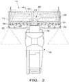
FIG. 2 illustrates the automatic lighting system for the header ofFIG. 1 ; and -
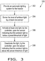
FIG. 3 illustrates a flowchart of a method for operating the lighting system, in accordance with an exemplary embodiment of the present invention. - The terms "forward", "rearward", "left" and "right", when used in connection with the agricultural harvester and/or components thereof are usually determined with reference to the direction of forward operative travel of the harvester, but they should not be construed as limiting. The terms "longitudinal" and "transverse" are determined with reference to the fore-and-aft direction of the agricultural harvester and are equally not to be construed as limiting.
- Referring now to the drawings, and more particularly to
FIG. 1 , there is shown an exemplary embodiment of anagricultural vehicle 100 in the form of acombine 100. However, theagricultural vehicle 100 may be in the form of any desiredagricultural vehicle 100, such as a windrower. Theagricultural vehicle 100 generally includes achassis 102, ground engaging wheels and/ortracks 104, afeeder housing 106, and aprime mover 108. Thecombine 100 may also include aheader 110, aseparating system 120, acleaning system 130, adischarge system 140, anonboard grain tank 150, and an unloading auger 160. - The
threshing system 120 may be of the axial-flow type, and thereby may include an axially displacedthreshing rotor 122 which is at least partially enclosed by arotor housing 124. Therotor housing 124 can include a rotor cage and perforated concaves. The cut crop is threshed and separated by the rotation ofrotor 122 within therotor housing 124 such that larger elements, for example stalks, leaves, and other MOG is discharged out of the rear ofagricultural vehicle 100 through thedischarge system 140. Smaller elements of crop material, such as grain and non-grain crop material, including particles lighter than grain, such as chaff, dust and straw, may pass through the perforations in the concaves and onto thecleaning system 130. - The
cleaning system 130 may include agrain pan 131, a sieve assembly which can include an optionalpre-cleaning sieve 132, an upper sieve 133 (also known as a chaffer sieve), a lower sieve 134 (also known as a cleaning sieve), and acleaning fan 135. Thegrain pan 131 and pre-cleaningsieve 132 may oscillate in a fore-to-aft manner to transport the grain and finer non-grain crop material to theupper sieve 133. Theupper sieve 133 andlower sieve 134 are vertically arranged relative to each other, and may also oscillate in a fore-to-aft manner to spread the grain acrosssieves sieves fan 135 may provide an airstream through thesieves agricultural vehicle 100. - The
cleaning system 130 may also include aclean grain auger 136 positioned crosswise below and toward the front end of thesieves clean grain auger 136 receives clean grain from eachsieve bottom pan 137 of thecleaning system 130. Theclean grain auger 136 conveys the clean grain laterally to a generally vertically arrangedgrain elevator 138 for transport to thegrain tank 150. Thecleaning system 130 may additionally include one or more tailings returnaugers 139 for receiving tailings from thesieves cleaning system 130 for repeated threshing and/or cleaning action. Once thegrain tank 150 becomes full, the clean grain therein may be transported by the unloading auger 160 into a service vehicle. - The
header 110 is removably attached to thefeeder housing 106. Theheader 110 generally includes aframe 112, acutter bar 114 that severs the crop from a field, arotatable reel 116 rotatably mounted to theframe 112, which feeds the cut crop into theheader 110, and aconveyor 118, e.g. anauger 118 with flighting, that feeds the severed crop inwardly from each lateral end of theframe 112 towardfeeder housing 106. Theheader 110 may be in the form of any desired header, such as a draper header or a corn header. As can be appreciated, theheader 110 may be at least partially lifted or carried by thefeeder housing 106, which typically includes an actuating system with one or more hydraulic cylinders. - Referring now collectively to
FIGS. 1-2 , there is shown an exemplary embodiment of anautomatic lighting system 200 for theheader 110. Theautomatic lighting system 200 generally includes at least one light 202, at least onesensor 204 for sensing a level of light surrounding theheader 110, and an electronic control unit (ECU) 210, e.g. acontroller 210 with amemory 212. Thecontroller 210 automatically operates the light(s) 202 upon communicating with the sensor(s) 204. - The light(s) 202 may be connected to the
frame 112 of theheader 110 at any desired location. As shown, theautomatic lighting system 200 includes fourlights 202 with twolights 202 being attached to the lateral ends of theframe 112, for illuminating an area behind theframe 112, and twolights 202 being attached inwardly from the lateral ends of theframe 112, for illuminating theframe 112 where crop enters and flows through theheader 110. However, it should be appreciated that theautomatic lighting system 200 may include any number oflights 202 for illuminating any desired area located on or around theheader 110. Each light 202 may be in the form of any desired light, such as an incandescent light bulb or light emitting diode (LED). - The
automatic lighting system 200 includes a pair ofsensors 204 in the form of left andright sensors 204 that are respectively located at the left and right ends of theheader 110. However, theautomatic lighting system 200 may include only one or more than twosensors 204. The sensor(s) 204 may be located at any desired location on theframe 112 of theheader 110. Eachsensor 204 may be located on a top surface, an inside surface, or an outside surface at a respective lateral end of theframe 112. Alternatively, the sensor(s) 204 may be positioned near the front of theheader 110, where theheader 110 engages crop, or at a middle portion of theheader 110. It is noted that having twosensors 204 at the left and right ends of theheader 110 prevents any interruption of theautomatic lighting system 200 when the shadow of theagricultural vehicle 100, in dusk or dawn lighting conditions, undesirably shades one of thesensors 204. Eachsensor 204 may be in the form of an ambientlight sensor 204 for sensing the ambient light at any desired location within or around theheader 110 and providing a corresponding signal. The ambientlight sensor 204 may be in the form of any desired photosensor which may sense light and/or electromagnetic radiation. Each ambientlight sensor 204 may have a preset threshold of the level of light which is indicative of low-light conditions. As used herein, the term "preset threshold of the level of light" may refer to any level or amount of ambient light at which an operator may desire an improved visibility to see theheader 110 and/or surrounding areas thereof. The preset threshold of light may be the known level of light at which low-light conditions exist, for example during dusk, dawn, and/or nighttime. As can be appreciated, eachsensor 204 may sense any form of light, such as light which is emitted from the sun and/or any other artificial light source. Additionally or alternatively, the sensor(s) 204 may be located on theagricultural vehicle 100. Each sensor located on theagricultural vehicle 100 may provide feedback which is closely representative to sensor(s) 204 located on theheader 110. - According to a further aspect of the exemplary embodiment of the present invention, the sensor(s) 204 may detect the ambient light emitted from the lights of the
agricultural vehicle 100, and thecontroller 210 may correspondingly turn on the light(s) 202 upon the sensor(s) 204 indicating that the lights of theagricultural vehicle 100 have already turned on. Automatically turning on the light(s) 202 of theheader 110 when the lights of theagricultural vehicle 100 are turned on may be beneficial if improved visibility is desired even when ambient low-light conditions do not exist or when there is no option to manually turn on the light(s) 202, as with some older model agricultural vehicles. - The
controller 210 may be operably connected to the light(s) 202 and sensor(s) 204. Thecontroller 210 may automatically activate or deactivate the light(s) 202 upon the sensor(s) 204 reading that the ambient light is below or above the preset threshold of light, respectively. Thecontroller 210 may be in the form of any desired analog or digital control unit. Thememory 212 may be in the form of any desired tangible computer readable medium, and thememory 212 may store any desired information, such as the preset threshold value of ambient light which is indicative of low-light conditions. Thecontroller 210 may interface with and/or be incorporated into existing hardware and/or software of theheader 110 and/oragricultural vehicle 100. In other words, thecontroller 210 may be a separate unit as part of theautomatic lighting system 200 and/or be integrated with theheader 110 and/oragricultural vehicle 100. For instance, theheader 110 may have a dedicated header controller which controls specific header-related functions, and thecontroller 210 may either be in the form of the dedicated header controller or be incorporated as part of the dedicated header controller. - According to another aspect of the exemplary embodiment of the present invention, the
controller 210 may account for the rotational movement of thereel 116. In certain lighting conditions, thereel 116 may periodically block or prevent the sensor(s) 204 from sensing the ambient light. For example, the rotational speed of thereel 116 may be proportionate to one or more frequencies which may interfere with the sensor(s) 204 and thereby cause periodic shadowing of the sensor(s) 204. To mitigate the effect of this periodic shadowing, thecontroller 210 may calculate an adjusted input for filtering out the interreference caused by thereel 116. For example, thecontroller 210 may communicate with aspeed sensor 206 of thereel 116, use the measured speed of thereel 116 to calculate a corresponding frequency of thereel 116, and then filter out the frequency of thereel 116 from the signal(s) of the sensor(s) 204. It should be appreciated that thereel speed sensor 206 may be operably coupled to thecontroller 210 by a wired or wireless connection. For instance, thereel speed sensor 206 may communicate to thecontroller 210 via a connected bus network. - Referring now to
FIG. 3 , there is shown a flowchart of amethod 300 for operating theagricultural vehicle 100, and more particularly theautomatic lighting system 200, in various lighting conditions, such as in low-light conditions. Themethod 300 may include an initial step of providing theheader 110 with theautomatic lighting system 200 as described above (at block 302). Themethod 300 includes a step of sensing the level of ambient light by the sensor(s) 204 (at block 304). Themethod 300 may also include a step of automatically activating the light(s) 202, by thecontroller 210, upon the sensor(s) 204 sensing that the level of light is below a preset threshold of light (at block 306). Themethod 300 may then include a step of automatically deactivating the light(s) 202, by thecontroller 210, upon the sensor(s) 204 sensing that the level of light is above the preset threshold of light (at block 308). Further, themethod 300 may include another step of filtering interference, by thecontroller 210, upon thereel 116 blocking the sensor(s) 204. Herein, thecontroller 210 may identify the frequency of therotating reel 116 and filter out any interference in the signal(s) of the sensor(s) 204 caused by the frequency of thereel 116. It should be appreciated that theautomatic lighting system 200 may automatically turn on or off the light(s) 202 depending upon a set time of day. Additionally, if theagricultural vehicle 100 includes a user interface, e.g. a control panel or switch, the operator may input a control command to operate theautomatic lighting system 200. - It is to be understood that the steps of the
method 300 are performed by thecontroller 210 upon loading and executing software code or instructions which are tangibly stored on the tangible computerreadable medium 212, such as on a magnetic medium, e.g., a computer hard drive, an optical medium, e.g., an optical disc, solid-state memory, e.g., flash memory, or other storage media known in the art. Thus, any of the functionality performed by thecontroller 210 described herein, such as themethod 300, is implemented in software code or instructions which are tangibly stored on a tangible computer readable medium. Thecontroller 210 loads the software code or instructions via a direct interface with the computer readable medium or via a wired and/or wireless network. Upon loading and executing such software code or instructions by thecontroller 210, thecontroller 210 may perform any of the functionality of thecontroller 210 described herein, including any steps of themethod 300 described herein. - The term "software code" or "code" used herein refers to any instructions or set of instructions that influence the operation of a computer or controller. They may exist in a computer-executable form, such as machine code, which is the set of instructions and data directly executed by a computer's central processing unit or by a controller, a human-understandable form, such as source code, which may be compiled in order to be executed by a computer's central processing unit or by a controller, or an intermediate form, such as object code, which is produced by a compiler. As used herein, the term "software code" or "code" also includes any human-understandable computer instructions or set of instructions, e.g., a script, that may be executed on the fly with the aid of an interpreter executed by a computer's central processing unit or by a controller.
- These and other advantages of the present invention will be apparent to those skilled in the art from the foregoing specification. Accordingly, it is to be recognized by those skilled in the art that changes or modifications may be made to the above-described embodiments without departing from the broad inventive concepts of the invention. It is to be understood that this invention is not limited to the particular embodiments described herein, but is intended to include all changes and modifications that are within the scope and spirit of the invention.
Claims (7)
- A header (110) for an agricultural vehicle (100), comprising:a frame (112) comprising lateral ends;an automatic lighting system (200),characterized in that:the automatic lighting system (200) comprising at least one light (202) connected to the frame (112) and at least one sensor (204) connected to the frame (112) and configured for sensing a level of light (202) and providing a signal indicative of the level of light; andan electronic control unit (210) operably connected to the at least one light (202) and the at least one sensor (204), and the electronic control unit (210) being configured for automatically operating the at least one light (202) upon receiving the signal of the at least one sensor (204).
- The header (110) of claim 1, wherein the electronic control unit (210) automatically activates the at least one light (202) upon the at least one sensor (204) sensing that the level of light (202) is below a preset threshold of light.
- The header (110) of claim 2, wherein the electronic control unit (210) automatically deactivates the at least one light (202) upon the at least one sensor (204) sensing that the level of light (202) is above the preset threshold of light.
- The header (110) of any one of the preceding claims, wherein the at least one sensor (204) is in the form of at least one ambient light sensor (204).
- The header (110) of any one of the preceding claims, further comprising a reel (116), and wherein the electronic control unit (210) is configured for filtering interference caused by the reel (116).
- The header (110) of any one of the preceding claims, wherein the at least one sensor (204) comprises a pair of sensors (204), and each sensor (204) is located at a respective lateral end of the frame (112).
- The header (110) of any one of the preceding claims, wherein the automatic lighting system (200) comprises four lights (202) located on the frame (112), two lights (202) being respectively located at the lateral ends of the frame (112) for illuminating an area behind the frame (112), and two lights (202) being respectively located inwardly of the lateral ends of the frame (112) for illuminating the frame (112).
Applications Claiming Priority (1)
| Application Number | Priority Date | Filing Date | Title |
|---|---|---|---|
| US16/545,621 US10829033B1 (en) | 2019-08-20 | 2019-08-20 | Automatically controlled header work lights |
Publications (2)
| Publication Number | Publication Date |
|---|---|
| EP3782452A1 true EP3782452A1 (en) | 2021-02-24 |
| EP3782452B1 EP3782452B1 (en) | 2024-10-09 |
Family
ID=72148033
Family Applications (1)
| Application Number | Title | Priority Date | Filing Date |
|---|---|---|---|
| EP20191792.9A Active EP3782452B1 (en) | 2019-08-20 | 2020-08-19 | Automatically controlled header work lights |
Country Status (3)
| Country | Link |
|---|---|
| US (1) | US10829033B1 (en) |
| EP (1) | EP3782452B1 (en) |
| BR (1) | BR102020016577A2 (en) |
Families Citing this family (12)
| Publication number | Priority date | Publication date | Assignee | Title |
|---|---|---|---|---|
| DE102019110098A1 (en) * | 2018-07-27 | 2020-01-30 | Claas Selbstfahrende Erntemaschinen Gmbh | Arrangement of an attachment and a self-propelled harvesting machine and self-propelled harvesting machine for such an arrangement |
| US11659787B2 (en) * | 2020-04-03 | 2023-05-30 | Cnh Industrial America Llc | Harvesting head reel-crop engagement |
| US11950538B2 (en) * | 2020-05-19 | 2024-04-09 | Deere & Company | Commodity cart with improved loading positioning |
| US11716795B2 (en) * | 2020-06-30 | 2023-08-01 | Deere & Company | Method of controlling an agricultural vehicle lighting system and system thereof |
| US11364838B2 (en) * | 2020-06-30 | 2022-06-21 | Deere & Company | Method of controlling an agricultural vehicle lighting system and system thereof |
| US12364181B2 (en) | 2020-11-02 | 2025-07-22 | Deere & Company | Agricultural characteristic confidence and control |
| US12022772B2 (en) | 2021-01-22 | 2024-07-02 | Deere & Company | Agricultural header control |
| US11747536B2 (en) * | 2021-05-27 | 2023-09-05 | Deere & Company | Header reel illumination |
| US12550821B2 (en) | 2022-03-15 | 2026-02-17 | Deere & Company | Systems and methods for predictive reel control |
| US12302788B2 (en) | 2022-04-08 | 2025-05-20 | Deere &Company | Residue characteristic confidence and control |
| US12507628B2 (en) | 2022-10-13 | 2025-12-30 | Deere & Company | Agricultural system with deck plate positioning control |
| GB2628088A (en) * | 2023-03-09 | 2024-09-18 | Jaguar Land Rover Ltd | Vehicle lighting system control |
Citations (6)
| Publication number | Priority date | Publication date | Assignee | Title |
|---|---|---|---|---|
| EP2158799A1 (en) * | 2008-08-27 | 2010-03-03 | CLAAS Tractor S.A.S. | Self-propelled agricultural working machine |
| US20160121784A1 (en) * | 2013-06-03 | 2016-05-05 | Ponsse Oyj | System for Controlling Work Lights in a Forestry Machine |
| US20170066365A1 (en) * | 2015-09-03 | 2017-03-09 | Deere & Company | Arrangement for controlling a lighting device of a working vehicle |
| US20180236928A1 (en) * | 2017-02-21 | 2018-08-23 | Deere & Company | Adaptive lighting system of an off-road utility vehicle |
| WO2019036674A1 (en) * | 2017-08-18 | 2019-02-21 | Cnh Industrial America Llc | System and method for automatically adjusting lighting configurations for a work vehicle |
| US20190118701A1 (en) * | 2017-10-24 | 2019-04-25 | Robert Bosch Gmbh | Car light sensor warning for headlights |
Family Cites Families (12)
| Publication number | Priority date | Publication date | Assignee | Title |
|---|---|---|---|---|
| US4009555A (en) * | 1976-02-26 | 1977-03-01 | Massey-Ferguson Inc. | Height control for combine headers |
| US4502270A (en) * | 1984-02-02 | 1985-03-05 | Allis-Chalmers Corporation | Crop divider with illuminated points |
| US5246285A (en) * | 1991-04-11 | 1993-09-21 | Loren Redburn | Automatic interior lighting device for drawers, cabinets and the like |
| US5161874A (en) * | 1991-05-22 | 1992-11-10 | Mitchell C. Radov | Remote illumination system |
| US9955551B2 (en) * | 2002-07-12 | 2018-04-24 | Yechezkal Evan Spero | Detector controlled illuminating system |
| US7748489B2 (en) * | 2008-10-31 | 2010-07-06 | Deere & Company | Agricultural header presence sensor with traction control |
| US8292462B2 (en) * | 2009-10-06 | 2012-10-23 | Tsun-Yu Huang | Lamp seat structure capable of adjusting light source sensing direction |
| US8868304B2 (en) | 2012-02-10 | 2014-10-21 | Deere & Company | Method and stereo vision system for facilitating the unloading of agricultural material from a vehicle |
| US10371561B2 (en) | 2013-11-01 | 2019-08-06 | Iowa State University Research Foundation, Inc. | Yield measurement and base cutter height control systems for a harvester |
| US20150195991A1 (en) * | 2014-01-15 | 2015-07-16 | Cnh America Llc | Header height control system for an agricultural harvester |
| DE102015112437A1 (en) | 2015-07-29 | 2017-02-02 | Claas Saulgau Gmbh | Control unit for an agricultural train and method for operating an agricultural train |
| DE102019110098A1 (en) * | 2018-07-27 | 2020-01-30 | Claas Selbstfahrende Erntemaschinen Gmbh | Arrangement of an attachment and a self-propelled harvesting machine and self-propelled harvesting machine for such an arrangement |
-
2019
- 2019-08-20 US US16/545,621 patent/US10829033B1/en active Active
-
2020
- 2020-08-14 BR BR102020016577-1A patent/BR102020016577A2/en unknown
- 2020-08-19 EP EP20191792.9A patent/EP3782452B1/en active Active
Patent Citations (6)
| Publication number | Priority date | Publication date | Assignee | Title |
|---|---|---|---|---|
| EP2158799A1 (en) * | 2008-08-27 | 2010-03-03 | CLAAS Tractor S.A.S. | Self-propelled agricultural working machine |
| US20160121784A1 (en) * | 2013-06-03 | 2016-05-05 | Ponsse Oyj | System for Controlling Work Lights in a Forestry Machine |
| US20170066365A1 (en) * | 2015-09-03 | 2017-03-09 | Deere & Company | Arrangement for controlling a lighting device of a working vehicle |
| US20180236928A1 (en) * | 2017-02-21 | 2018-08-23 | Deere & Company | Adaptive lighting system of an off-road utility vehicle |
| WO2019036674A1 (en) * | 2017-08-18 | 2019-02-21 | Cnh Industrial America Llc | System and method for automatically adjusting lighting configurations for a work vehicle |
| US20190118701A1 (en) * | 2017-10-24 | 2019-04-25 | Robert Bosch Gmbh | Car light sensor warning for headlights |
Also Published As
| Publication number | Publication date |
|---|---|
| BR102020016577A2 (en) | 2021-03-23 |
| US10829033B1 (en) | 2020-11-10 |
| EP3782452B1 (en) | 2024-10-09 |
Similar Documents
| Publication | Publication Date | Title |
|---|---|---|
| EP3782452B1 (en) | Automatically controlled header work lights | |
| US11624650B2 (en) | Systems and methods for filtering sensor signal interference deriving from powered components of a header | |
| US9585309B2 (en) | Header height control system for an agricultural harvester | |
| US9913431B2 (en) | Agricultural harvester concave clamping system | |
| EP3672391B1 (en) | Adjustable fan based on grain throughput | |
| US10299435B2 (en) | Self-storing header auger | |
| EP3821693B1 (en) | Agricultural harvester with proactive response to moisture level of collected crop material | |
| EP3064052A1 (en) | An agricultural reel cam system | |
| US12477985B2 (en) | Active deck plate opening | |
| US20230062392A1 (en) | Autonomous header | |
| US20240155975A1 (en) | System and method for sensor-based monitoring of a harvesting operation | |
| WO2020126211A1 (en) | Grain cleaning system and method of controlling such | |
| US10080330B2 (en) | Variable amount of side shake based on user inputs | |
| US10257984B2 (en) | Agricultural harvester with paddles rotated about an axis of rotation that is parallel to a longitudinal axis of the harvester | |
| EP4218393B1 (en) | System and method for controlling threshing assembly operation of an agricultural harvester | |
| EP3991540B1 (en) | Systems and methods for filtering sensor signal interference deriving from powered components of a header | |
| US20240196791A1 (en) | Crop Residue Spreader Arrangement | |
| US10091940B2 (en) | Straw walker arrangement for an agricultural harvester | |
| US11653599B2 (en) | Remote infeed deck cleanout door for a header |
Legal Events
| Date | Code | Title | Description |
|---|---|---|---|
| PUAI | Public reference made under article 153(3) epc to a published international application that has entered the european phase |
Free format text: ORIGINAL CODE: 0009012 |
|
| STAA | Information on the status of an ep patent application or granted ep patent |
Free format text: STATUS: THE APPLICATION HAS BEEN PUBLISHED |
|
| AK | Designated contracting states |
Kind code of ref document: A1 Designated state(s): AL AT BE BG CH CY CZ DE DK EE ES FI FR GB GR HR HU IE IS IT LI LT LU LV MC MK MT NL NO PL PT RO RS SE SI SK SM TR |
|
| AX | Request for extension of the european patent |
Extension state: BA ME |
|
| STAA | Information on the status of an ep patent application or granted ep patent |
Free format text: STATUS: REQUEST FOR EXAMINATION WAS MADE |
|
| 17P | Request for examination filed |
Effective date: 20210824 |
|
| RBV | Designated contracting states (corrected) |
Designated state(s): AL AT BE BG CH CY CZ DE DK EE ES FI FR GB GR HR HU IE IS IT LI LT LU LV MC MK MT NL NO PL PT RO RS SE SI SK SM TR |
|
| GRAP | Despatch of communication of intention to grant a patent |
Free format text: ORIGINAL CODE: EPIDOSNIGR1 |
|
| STAA | Information on the status of an ep patent application or granted ep patent |
Free format text: STATUS: GRANT OF PATENT IS INTENDED |
|
| INTG | Intention to grant announced |
Effective date: 20240411 |
|
| GRAS | Grant fee paid |
Free format text: ORIGINAL CODE: EPIDOSNIGR3 |
|
| GRAA | (expected) grant |
Free format text: ORIGINAL CODE: 0009210 |
|
| STAA | Information on the status of an ep patent application or granted ep patent |
Free format text: STATUS: THE PATENT HAS BEEN GRANTED |
|
| AK | Designated contracting states |
Kind code of ref document: B1 Designated state(s): AL AT BE BG CH CY CZ DE DK EE ES FI FR GB GR HR HU IE IS IT LI LT LU LV MC MK MT NL NO PL PT RO RS SE SI SK SM TR |
|
| REG | Reference to a national code |
Ref country code: CH Ref legal event code: EP |
|
| REG | Reference to a national code |
Ref country code: DE Ref legal event code: R096 Ref document number: 602020038942 Country of ref document: DE |
|
| REG | Reference to a national code |
Ref country code: IE Ref legal event code: FG4D |
|
| REG | Reference to a national code |
Ref country code: LT Ref legal event code: MG9D |
|
| REG | Reference to a national code |
Ref country code: NL Ref legal event code: MP Effective date: 20241009 |
|
| REG | Reference to a national code |
Ref country code: AT Ref legal event code: MK05 Ref document number: 1729483 Country of ref document: AT Kind code of ref document: T Effective date: 20241009 |
|
| PG25 | Lapsed in a contracting state [announced via postgrant information from national office to epo] |
Ref country code: NL Free format text: LAPSE BECAUSE OF FAILURE TO SUBMIT A TRANSLATION OF THE DESCRIPTION OR TO PAY THE FEE WITHIN THE PRESCRIBED TIME-LIMIT Effective date: 20241009 |
|
| PG25 | Lapsed in a contracting state [announced via postgrant information from national office to epo] |
Ref country code: NL Free format text: LAPSE BECAUSE OF FAILURE TO SUBMIT A TRANSLATION OF THE DESCRIPTION OR TO PAY THE FEE WITHIN THE PRESCRIBED TIME-LIMIT Effective date: 20241009 |
|
| PG25 | Lapsed in a contracting state [announced via postgrant information from national office to epo] |
Ref country code: IS Free format text: LAPSE BECAUSE OF FAILURE TO SUBMIT A TRANSLATION OF THE DESCRIPTION OR TO PAY THE FEE WITHIN THE PRESCRIBED TIME-LIMIT Effective date: 20250209 Ref country code: HR Free format text: LAPSE BECAUSE OF FAILURE TO SUBMIT A TRANSLATION OF THE DESCRIPTION OR TO PAY THE FEE WITHIN THE PRESCRIBED TIME-LIMIT Effective date: 20241009 Ref country code: PT Free format text: LAPSE BECAUSE OF FAILURE TO SUBMIT A TRANSLATION OF THE DESCRIPTION OR TO PAY THE FEE WITHIN THE PRESCRIBED TIME-LIMIT Effective date: 20250210 |
|
| PG25 | Lapsed in a contracting state [announced via postgrant information from national office to epo] |
Ref country code: FI Free format text: LAPSE BECAUSE OF FAILURE TO SUBMIT A TRANSLATION OF THE DESCRIPTION OR TO PAY THE FEE WITHIN THE PRESCRIBED TIME-LIMIT Effective date: 20241009 |
|
| PG25 | Lapsed in a contracting state [announced via postgrant information from national office to epo] |
Ref country code: BG Free format text: LAPSE BECAUSE OF FAILURE TO SUBMIT A TRANSLATION OF THE DESCRIPTION OR TO PAY THE FEE WITHIN THE PRESCRIBED TIME-LIMIT Effective date: 20241009 |
|
| PG25 | Lapsed in a contracting state [announced via postgrant information from national office to epo] |
Ref country code: ES Free format text: LAPSE BECAUSE OF FAILURE TO SUBMIT A TRANSLATION OF THE DESCRIPTION OR TO PAY THE FEE WITHIN THE PRESCRIBED TIME-LIMIT Effective date: 20241009 |
|
| PG25 | Lapsed in a contracting state [announced via postgrant information from national office to epo] |
Ref country code: NO Free format text: LAPSE BECAUSE OF FAILURE TO SUBMIT A TRANSLATION OF THE DESCRIPTION OR TO PAY THE FEE WITHIN THE PRESCRIBED TIME-LIMIT Effective date: 20250109 |
|
| PG25 | Lapsed in a contracting state [announced via postgrant information from national office to epo] |
Ref country code: AT Free format text: LAPSE BECAUSE OF FAILURE TO SUBMIT A TRANSLATION OF THE DESCRIPTION OR TO PAY THE FEE WITHIN THE PRESCRIBED TIME-LIMIT Effective date: 20241009 Ref country code: LV Free format text: LAPSE BECAUSE OF FAILURE TO SUBMIT A TRANSLATION OF THE DESCRIPTION OR TO PAY THE FEE WITHIN THE PRESCRIBED TIME-LIMIT Effective date: 20241009 Ref country code: GR Free format text: LAPSE BECAUSE OF FAILURE TO SUBMIT A TRANSLATION OF THE DESCRIPTION OR TO PAY THE FEE WITHIN THE PRESCRIBED TIME-LIMIT Effective date: 20250110 |
|
| PG25 | Lapsed in a contracting state [announced via postgrant information from national office to epo] |
Ref country code: PL Free format text: LAPSE BECAUSE OF FAILURE TO SUBMIT A TRANSLATION OF THE DESCRIPTION OR TO PAY THE FEE WITHIN THE PRESCRIBED TIME-LIMIT Effective date: 20241009 |
|
| PG25 | Lapsed in a contracting state [announced via postgrant information from national office to epo] |
Ref country code: RS Free format text: LAPSE BECAUSE OF FAILURE TO SUBMIT A TRANSLATION OF THE DESCRIPTION OR TO PAY THE FEE WITHIN THE PRESCRIBED TIME-LIMIT Effective date: 20250109 |
|
| PG25 | Lapsed in a contracting state [announced via postgrant information from national office to epo] |
Ref country code: SM Free format text: LAPSE BECAUSE OF FAILURE TO SUBMIT A TRANSLATION OF THE DESCRIPTION OR TO PAY THE FEE WITHIN THE PRESCRIBED TIME-LIMIT Effective date: 20241009 |
|
| PG25 | Lapsed in a contracting state [announced via postgrant information from national office to epo] |
Ref country code: DK Free format text: LAPSE BECAUSE OF FAILURE TO SUBMIT A TRANSLATION OF THE DESCRIPTION OR TO PAY THE FEE WITHIN THE PRESCRIBED TIME-LIMIT Effective date: 20241009 |
|
| REG | Reference to a national code |
Ref country code: DE Ref legal event code: R097 Ref document number: 602020038942 Country of ref document: DE |
|
| PG25 | Lapsed in a contracting state [announced via postgrant information from national office to epo] |
Ref country code: EE Free format text: LAPSE BECAUSE OF FAILURE TO SUBMIT A TRANSLATION OF THE DESCRIPTION OR TO PAY THE FEE WITHIN THE PRESCRIBED TIME-LIMIT Effective date: 20241009 |
|
| PG25 | Lapsed in a contracting state [announced via postgrant information from national office to epo] |
Ref country code: RO Free format text: LAPSE BECAUSE OF FAILURE TO SUBMIT A TRANSLATION OF THE DESCRIPTION OR TO PAY THE FEE WITHIN THE PRESCRIBED TIME-LIMIT Effective date: 20241009 |
|
| PG25 | Lapsed in a contracting state [announced via postgrant information from national office to epo] |
Ref country code: SK Free format text: LAPSE BECAUSE OF FAILURE TO SUBMIT A TRANSLATION OF THE DESCRIPTION OR TO PAY THE FEE WITHIN THE PRESCRIBED TIME-LIMIT Effective date: 20241009 |
|
| PG25 | Lapsed in a contracting state [announced via postgrant information from national office to epo] |
Ref country code: CZ Free format text: LAPSE BECAUSE OF FAILURE TO SUBMIT A TRANSLATION OF THE DESCRIPTION OR TO PAY THE FEE WITHIN THE PRESCRIBED TIME-LIMIT Effective date: 20241009 |
|
| PLBE | No opposition filed within time limit |
Free format text: ORIGINAL CODE: 0009261 |
|
| STAA | Information on the status of an ep patent application or granted ep patent |
Free format text: STATUS: NO OPPOSITION FILED WITHIN TIME LIMIT |
|
| PG25 | Lapsed in a contracting state [announced via postgrant information from national office to epo] |
Ref country code: SE Free format text: LAPSE BECAUSE OF FAILURE TO SUBMIT A TRANSLATION OF THE DESCRIPTION OR TO PAY THE FEE WITHIN THE PRESCRIBED TIME-LIMIT Effective date: 20241009 |
|
| 26N | No opposition filed |
Effective date: 20250710 |
|
| PGFP | Annual fee paid to national office [announced via postgrant information from national office to epo] |
Ref country code: DE Payment date: 20250827 Year of fee payment: 6 |
|
| PGFP | Annual fee paid to national office [announced via postgrant information from national office to epo] |
Ref country code: IT Payment date: 20250825 Year of fee payment: 6 |
|
| PGFP | Annual fee paid to national office [announced via postgrant information from national office to epo] |
Ref country code: GB Payment date: 20250826 Year of fee payment: 6 |
|
| PGFP | Annual fee paid to national office [announced via postgrant information from national office to epo] |
Ref country code: FR Payment date: 20250825 Year of fee payment: 6 |
|
| REG | Reference to a national code |
Ref country code: CH Ref legal event code: H13 Free format text: ST27 STATUS EVENT CODE: U-0-0-H10-H13 (AS PROVIDED BY THE NATIONAL OFFICE) Effective date: 20260324 |
|
| PG25 | Lapsed in a contracting state [announced via postgrant information from national office to epo] |
Ref country code: MC Free format text: LAPSE BECAUSE OF FAILURE TO SUBMIT A TRANSLATION OF THE DESCRIPTION OR TO PAY THE FEE WITHIN THE PRESCRIBED TIME-LIMIT Effective date: 20241009 |
|
| PG25 | Lapsed in a contracting state [announced via postgrant information from national office to epo] |
Ref country code: LU Free format text: LAPSE BECAUSE OF NON-PAYMENT OF DUE FEES Effective date: 20250819 |
|
| PG25 | Lapsed in a contracting state [announced via postgrant information from national office to epo] |
Ref country code: CH Free format text: LAPSE BECAUSE OF NON-PAYMENT OF DUE FEES Effective date: 20250831 |