EP3782445A1 - Agricultural input placement system and method - Google Patents
Agricultural input placement system and method Download PDFInfo
- Publication number
- EP3782445A1 EP3782445A1 EP20183817.4A EP20183817A EP3782445A1 EP 3782445 A1 EP3782445 A1 EP 3782445A1 EP 20183817 A EP20183817 A EP 20183817A EP 3782445 A1 EP3782445 A1 EP 3782445A1
- Authority
- EP
- European Patent Office
- Prior art keywords
- liquid
- seed
- control actuator
- actuator
- modifies
- Prior art date
- Legal status (The legal status is an assumption and is not a legal conclusion. Google has not performed a legal analysis and makes no representation as to the accuracy of the status listed.)
- Granted
Links
Images





Classifications
-
- A—HUMAN NECESSITIES
- A01—AGRICULTURE; FORESTRY; ANIMAL HUSBANDRY; HUNTING; TRAPPING; FISHING
- A01C—PLANTING; SOWING; FERTILISING
- A01C23/00—Distributing devices specially adapted for liquid manure or other fertilising liquid, including ammonia, e.g. transport tanks or sprinkling wagons
- A01C23/02—Special arrangements for delivering the liquid directly into the soil
- A01C23/023—Special arrangements for delivering the liquid directly into the soil for liquid or gas fertilisers
-
- A—HUMAN NECESSITIES
- A01—AGRICULTURE; FORESTRY; ANIMAL HUSBANDRY; HUNTING; TRAPPING; FISHING
- A01B—SOIL WORKING IN AGRICULTURE OR FORESTRY; PARTS, DETAILS, OR ACCESSORIES OF AGRICULTURAL MACHINES OR IMPLEMENTS, IN GENERAL
- A01B63/00—Lifting or adjusting devices or arrangements for agricultural machines or implements
- A01B63/002—Devices for adjusting or regulating the position of tools or wheels
- A01B63/008—Vertical adjustment of tools
-
- A—HUMAN NECESSITIES
- A01—AGRICULTURE; FORESTRY; ANIMAL HUSBANDRY; HUNTING; TRAPPING; FISHING
- A01C—PLANTING; SOWING; FERTILISING
- A01C23/00—Distributing devices specially adapted for liquid manure or other fertilising liquid, including ammonia, e.g. transport tanks or sprinkling wagons
- A01C23/02—Special arrangements for delivering the liquid directly into the soil
- A01C23/027—Other methods for delivering fertiliser into the soil
- A01C23/028—Contactless injection into the soil
-
- A—HUMAN NECESSITIES
- A01—AGRICULTURE; FORESTRY; ANIMAL HUSBANDRY; HUNTING; TRAPPING; FISHING
- A01C—PLANTING; SOWING; FERTILISING
- A01C7/00—Sowing
- A01C7/06—Seeders combined with fertilising apparatus
-
- A—HUMAN NECESSITIES
- A01—AGRICULTURE; FORESTRY; ANIMAL HUSBANDRY; HUNTING; TRAPPING; FISHING
- A01C—PLANTING; SOWING; FERTILISING
- A01C7/00—Sowing
- A01C7/08—Broadcast seeders; Seeders depositing seeds in rows
- A01C7/10—Devices for adjusting the seed-box ; Regulation of machines for depositing quantities at intervals
- A01C7/102—Regulating or controlling the seed rate
- A01C7/105—Seed sensors
Definitions
- FIG. 1 illustrates a tractor 5 traveling along a direction of travel T and drawing an agricultural implement 10, e.g., a planter, comprising a toolbar 14 operatively supporting multiple row units 200.
- An implement monitor 50 preferably including a central processing unit (“CPU”), memory and graphical user interface (“GUI”) (e.g., a touch-screen interface) is preferably located in the cab of the tractor 5.
- GUI graphical user interface
- a global positioning system (“GPS”) receiver 52 is preferably mounted to the tractor 5.
- GPS global positioning system
- the row unit 200 is a planter row unit.
- the row unit 200 is preferably pivotally connected to the toolbar 14 by a parallel linkage 216.
- An actuator 218 is preferably disposed to apply lift and/or downforce on the row unit 200.
- a solenoid valve 390 is preferably in fluid communication with the actuator 218 for modifying the lift and/or downforce applied by the actuator.
- An opening system 234 preferably includes two opening discs 244 rollingly mounted to a downwardly-extending shank 254 and disposed to open a v-shaped trench 38 in the soil 40.
- a pair of gauge wheels (not shown due to cutaway) is pivotally supported by a pair of corresponding gauge wheel arms 260; the height of the gauge wheels relative to the opening discs 244 sets the depth of the trench 38.
- a depth adjustment rocker 268 limits the upward travel of the gauge wheel arms 260 and thus the upward travel of the gauge wheels.
- a depth adjustment actuator 380 is preferably configured to modify a position of the depth adjustment rocker 268 and thus the height of the gauge wheels.
- the actuator 380 is preferably a linear actuator mounted to the row unit 200 and pivotally coupled to an upper end of the rocker 268.
- the depth adjustment actuator 380 comprises a device such as that disclosed in International Patent Application No. PCT/US2012/035585 ("the '585 application").
- An encoder 382 is preferably configured to generate a signal related to the linear extension of the actuator 380; it should be appreciated that the linear extension of the actuator 380 is related to the depth of the trench 38 when the gauge wheel arms 260 are in contact with the rocker 268.
- a downforce sensor 392 is preferably configured to generate a signal related to the amount of force imposed by the gauge wheels on the soil 40; in some embodiments the downforce sensor 392 comprises an instrumented pin about which the rocker 268 is pivotally coupled to the row unit 200, such as those instrumented pins disclosed in Applicant's U.S. Patent Application No. 12/522,253 (Pub. No. US 2010/0180695 ).
- a seed meter 230 such as that disclosed in Applicant's International Patent Application No. PCT/US2012/030192 is preferably disposed to deposit seeds 42 from a hopper 226 into the trench 38, e.g., through a seed tube 232 disposed to guide the seeds toward the trench.
- the meter is powered by an electric drive 315 configured to drive a seed disc within the seed meter.
- the drive 315 may comprise a hydraulic drive configured to drive the seed disc.
- a seed sensor 305 (e.g., an optical or electromagnetic seed sensor configured to generate a signal indicating passage of a seed) is preferably mounted to the seed tube 232 and disposed to send light or electromagnetic waves across the path of seeds 42.
- a closing system 236 including one or more closing wheels is pivotally coupled to the row unit 200 and configured to close the trench 38.
- a liquid outlet 650 is preferably disposed above the trench 38 for deposition of liquid (e.g., fertilizer) into the trench (i.e., planting furrow). Liquid is communicated to the liquid outlet 650 via a tube or conduit 652 from a liquid source (not shown).
- the liquid outlet 650 may be pivotally mounted, e.g. to a bracket 610 mounted to the shank 254.
- a positioning control actuator 600 preferably moves (e.g., reorient, positionally adjust, pivot, translate, rotate, redirect, reshape) the liquid outlet 650 and/or a liquid (e.g., stream, droplet, spray) deposited by the implement 10 (e.g., through the liquid outlet 650).
- the positioning control actuator preferably modifies the position (e.g., relative to the row unit 200) at which crop input (e.g., liquid, fertilizer) is deposited on the soil.
- crop input e.g., liquid, fertilizer
- the positioning control actuator 600 is mounted to the row unit 200 by an appropriate connection (e.g., using a mounting bracket) so as to be able to change the position/direction of the liquid outlet 650.
- the mounting position is not important and can be installed at any available position on row unit 200.
- positioning control actuator 600 is mounted to a row unit 200 via mounting bracket 601.
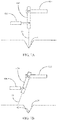
- the positioning control actuator 600 of FIG. 2 is illustrated in a first configuration in FIG. 6A and in a second configuration in FIG. 6B . It should also be appreciated that in FIG. 6B the row unit 200 is shown advanced along the direction of travel T relative to the position of FIG. 6B while the trench 38 and seeds 42 are shown in the same position in both drawing figures.
- the positioning control actuator 600 e.g., a linear actuator
- the positioning control actuator 600 is extended to a first extent such that the liquid outlet 650 is at a first orientation.
- a direction of liquid travel e.g., orientation of a stream or droplet movement
- Sa is generally along an axis Sa.
- the positioning control actuator 600 is extended to a second extent (e.g., a lesser extent such that the positioning control actuator is shortened) such that the liquid outlet 650 is at a second orientation (e.g., raised relative to the first orientation).
- a direction of liquid travel is generally along an axis Sb (e.g., raised relative to the axis Sa).
- the positioning control actuator 600 may be used according to some implementations to control the positioning of a crop input (e.g., liquid, fertilizer) relative to seed deposited by the row unit 200 in the trench 38.
- a crop input e.g., liquid, fertilizer
- reconfiguring the positioning control actuator 600 (and thus reorienting the liquid outlet 650) when the row unit 200 is in the position of FIG. 6B preferably causes the liquid stream to avoid the seed which would have otherwise intersected the axis Sa.
- the positioning control actuator 600 may be used to direct liquid away from a seed (e.g., to avoid depositing liquid directly to a seed).
- the positioning control actuator 600 may be used to direct liquid toward a seed.
- the illustrated reorientation is a longitudinal reorientation, e.g., reorientation in a plane longitudinal to the direction of travel.
- the positioning control actuator 600 may be any device suited to adjust the position of liquid deposition as desired, e.g., a servo motor, stepper motor.
- the positioning control actuator may be a motor having an output shaft mounted to a cam which contacts (e.g., slides against or rotates) the liquid outlet 650 to move the liquid outlet between a first and second position.
- the monitor 50 is preferably in data communication with components associated with each row unit 200 including the drives 315, the seed sensors 305, the GPS receiver 52, the downforce sensors 392, the valves 390, the depth adjustment actuator 380, and the depth actuator encoders 382.
- the monitor 50 is also preferably in data communication with clutches 310 configured to selectively operably couple the seed meter 230 to the drive 315.
- the monitor 50 is preferably in data communication with a cellular modem 330 or other component configured to place the monitor 50 in data communication with the Internet, indicated by reference numeral 335. Via the Internet connection, the monitor 50 preferably receives data from a weather data server 340 and a soil data server 345.
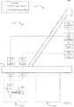
- FIGs. 3 and 5 also schematically illustrate a liquid control system 500.
- a primary source 505 e.g., liquid tank
- a primary pump 510 e.g., liquid pump
- the primary pump may be configured to selectively impose an adjustable commanded flow rate or pressure in the liquid conduit.
- a flow sensor 570-1 is preferably in fluid communication (e.g., in series or in parallel) with the primary liquid conduit and preferably generates a signal related to the flow rate of fluid in the primary liquid conduit.
- a primary rate controller 520 e.g., flow control valve, rate control valve, fluid injector
- a secondary source 525 may be mounted to the implement frame and preferably contains a secondary crop input (e.g., fertilizer).
- the secondary source contains fertilizer in a greater concentration than the primary source; in other embodiments, the primary source contains a carrier liquid such as water and the secondary source contains a fertilizer (e.g., liquid fertilizer and/or dry fertilizer) for injection into the carrier liquid.
- a secondary pump 530 e.g., liquid pump
- a secondary liquid conduit such as a flexible hose.
- the secondary pump may be configured to selectively impose an adjustable commanded flow rate or pressure in the liquid conduit.
- a flow sensor 572 is preferably in fluid communication (e.g., in series or in parallel) with the secondary liquid conduit and preferably generates a signal related to the flow rate of fluid in the secondary liquid conduit.
- a secondary rate controller 540 e.g., flow control valve, rate control valve, fluid injector preferably receives fluid from the primary source 525 and preferably modifies a flow rate in the secondary liquid conduit in response to a command signal.
- the primary and secondary liquid conduits preferably combine into a single flow stream which is preferably deposited from the liquid outlet 650.
- a shut-off valve 560 preferably selectively prevents or allows flow from the liquid outlet 650.
- the positioning actuator preferably selectively modifies a position and/or orientation of the liquid outlet 650 and/or selectively modifies a direction or pattern of flow from the liquid outlet in response to a command signal.
- the components of the liquid control system 500 are preferably in data communication with the monitor 50 for transfer of data (e.g., data signals corresponding to flow rates, pressures, valve positions, actuator positions) to the monitor 50 and receipt of commands (e.g., command signals corresponding to flow rates, pressures, valve states, actuator positions) from the monitor 50.
- data e.g., data signals corresponding to flow rates, pressures, valve positions, actuator positions
- commands e.g., command signals corresponding to flow rates, pressures, valve states, actuator positions
- some or all of the components of the liquid control system 500 are in data communication with the monitor 50 via a data bus 60 (e.g., a CAN bus), preferably by the use of a bus transceiver 66 (e.g., a CAN transceiver).
- a bus transceiver 66 e.g., a CAN transceiver
- some or all of the components of the liquid control system 500 are in data communication with the monitor 50 via a first wireless transceiver 62 (e.g., mounted to the row unit 200) and a second wireless transceiver 64 (e.g., in the tractor 5 or on the implement toolbar).
- the wireless transceivers 62 at each row unit are preferably in data communication with a single wireless transceiver 64 which is in turn in data communication with the monitor 50.
- the wireless transceiver may be mounted to the toolbar 14 or in the cab of the tractor 5.
- the wireless transceiver 62 and/or the wireless transceiver 64 may be replaced or supplemented with a wireless transmitter and/or a wireless transmitter.
- FIGs. 7A and 7B an alternative embodiment is illustrated in a first and second configuration, respectively, from a rear elevation view such that the direction of travel is into the page in both drawing figures.
- positioning control actuator 600 is extended such that the liquid outlet 650 is in a first orientation in which liquid is deposited along an axis Sa which may intersect the trench 38 (e.g., the bottom of the trench).
- the positioning control actuator 600 is shortened such that the liquid outlet 650 is reoriented to a second orientation in which liquid is deposited along an axis Sb which does not intersect the trench 38 (or in some embodiments, intersects a vertically higher portion of a sidewall of the trench rather than the bottom of the trench).
- the illustrated reorientation is a transverse reorientation, e.g., reorientation in a plane transverse to the direction of travel.
- the embodiment of FIGs. 7A, 7B may be used to modify the position of liquid deposition relative to a seed.
- the liquid outlet 650 is not disposed above a seed 42
- the implement has moved forward slightly such that the liquid outlet 650 is disposed above a seed 42; reorientation of the liquid outlet 650 thus avoids deposition of liquid directly to seed 42.
- a rotational actuator e.g., electric motor
- a linear actuator may be used rather than a linear actuator to reorient the liquid outlet 650.
- the positioning control actuator 600 comprises a nozzle configured to selectively change a pattern and/or area of liquid deposition (e.g., relative to a seed trench or seed).
- the actuator 600 extends a tip 682 partially outside of a nozzle body 680 (shown in partial cross-section) such that liquid released from the liquid outlet 650 is deposited over a relatively narrow area Aa (e.g., an area entirely within the trench 38).
- a relatively narrow area Aa e.g., an area entirely within the trench 38.
- the actuator 600 retracts the tip 682 toward (e.g., fully within) the nozzle body 680 such that liquid released from the liquid outlet 650 is deposited in a wider (e.g., hollow circular) pattern which preferably extends over a wider area Ab than the area Aa.
- the area Ab may extend beyond the trench 38.
- FIGs. 8A, 8B may be used to modify the position and/or area of liquid deposition relative to a seed. For example, in FIG. 8A the liquid outlet 650 is not disposed above a seed 42, whereas in FIG.
- the implement has moved forward slightly such that the liquid outlet 650 is disposed above a seed 42; adjustment of the nozzle tip 682 thus spreads the area of liquid application applied adjacent to seed 42, and in some embodiments may avoid liquid application on the seed 42 (e.g., by creating a hollow circular spray pattern around the seed 42 when viewed from above).
- This embodiment can be combined with any other embodiment described herein, such as the ones in FIGs. 6A, 6B , 7A, 7B , 9A, and 9B .
- FIGs. 9A and 9B another embodiment is illustrated in which the positioning control actuator 600 modifies an axial position of the liquid outlet 650 in a direction of liquid flow.
- the liquid outlet 650 is connected to positioning control actuator 600 which can oscillate the liquid outlet 650 as indicated by arrow 601 between a retracted position ( FIG. 9A ) and an extended position ( FIG. 9B ).
- This embodiment may be combined with any other embodiments described herein, such as those illustrated and described in FIGs. 6A, 6B , 7A, 7B , 8A and 8B .
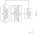
- FIG. 4 illustrates a method of using any of the embodiments described herein to modify the position and/or area of liquid deposition relative to a seed.
- the monitor 50 preferably predicts an in-furrow seed position.
- the monitor 50 may predict the in-furrow seed position by (1) determining a position of the implement based on a GPS signal from the GPS receiver 52, (2) determining a seed deposition location by applying in-memory offsets to the implement position, (3) determining a time of seed deposition based on a seed detection signal (e.g., from an optical or other electromagnetic seed sensor mounted to a seed tube or seed-to-ground delivery apparatus, or from an optical or other seed sensor disposed on a seed firmer) and/or a metering criterion such as a meter speed or position.
- a seed detection signal e.g., from an optical or other electromagnetic seed sensor mounted to a seed tube or seed-to-ground delivery apparatus, or from an optical or other seed sensor disposed on a seed firmer
- the monitor 50 preferably determines a time, quantity, and/or direction of position control actuation to obtain a desired input placement relative to the predicted seed position. For example, in cases where it is desired to reduce the amount of fluid directly deposited the monitor 50 may determine that the position actuator should modify its configuration (e.g., to one of the second configurations shown in FIGs. 6B , 7B , or 8B ) when the liquid outlet 650 is above a seed.
- the monitor 430 preferably executes the position control actuation at the time determined at step 420. The process 400 is preferably repeated as the implement moves through the field such that the desired placement relative to each seed is obtained.
- the process 400 additionally include a step of determining whether a predictability of seed location is above a sufficient threshold to carry out the process 400.
- the predictability of seed location may correspond to a seed singulation or seed spacing metric determined by the monitor 50. If the predictability of seed location is below the threshold, the monitor 50 may command the actuator 600 to remain in one of the first configurations of FIGs. 6A , 7A, 7B and optionally reduce the rate of liquid fertilizer application to a level determined to be safe for direct application to the seeds, or in some cases the rate of liquid fertilizer application may be set to zero using one or more components of the liquid control system 500.
- the liquid outlet 650 and the positioning actuator 600 may be disposed longitudinally forward of (i.e., along the travel direction T) the seed tube.
- the process 400 is preferably modified to predict the position of seeds to be deposited in the trench 38 and adjust the positioning actuator 600 to modify the position of crop input positioning relative to locations at which a seed is predicted to be planted.
- the positioning actuator 600 is actuated to create areas of the trench having no or reduced liquid application, which areas may correspond to areas of predicted seed locations.
Landscapes
- Life Sciences & Earth Sciences (AREA)
- Soil Sciences (AREA)
- Environmental Sciences (AREA)
- Engineering & Computer Science (AREA)
- Water Supply & Treatment (AREA)
- Mechanical Engineering (AREA)
- Fertilizing (AREA)
- Sowing (AREA)
- Pretreatment Of Seeds And Plants (AREA)
- Catching Or Destruction (AREA)
Abstract
Description
- In recent years, the availability of advanced location-specific agricultural application and measurement systems (used in so-called "precision farming" practices) has increased grower interest in determining spatial variations in soil properties and in varying input application variables in light of such variations. However, the available mechanisms for achieving optimal or desired placement of secondary inputs such as liquid fertilizer are lacking, leaving growers to choose between sub-optimal placement and/or amounts of such inputs. Thus, there is a need in the art for improved systems, methods and apparatus for agricultural input placement.
-
-
FIG. 1 is a top view of an embodiment of an agricultural planter. -
FIG. 2 is a partial-cutaway side elevation view of an embodiment of a planter row unit. -
FIG. 3 schematically illustrates an embodiment of a crop input application system. -
FIG. 4 illustrates a method of controlling crop input placement. -
FIG 5 is a schematic top view illustration of a liquid control system. -
FIG. 6A is a side elevation view of an embodiment of a position control actuator in a first configuration. -
FIG. 6B is a side elevation view of the position control actuator ofFIG. 6A in a second configuration. -
FIG. 7A is a rear elevation view of another embodiment of a position control actuator in a first configuration. -
FIG. 7B is a rear elevation view of the position control actuator ofFIG. 7A in a second configuration. -
FIG. 8A is a rear elevation view of still another embodiment of a position control actuator in a first configuration. -
FIG. 8B is a rear elevation view of the position control actuator ofFIG. 8A in a second configuration. -
FIG. 9A is a side elevation view of an embodiment of a position control actuator in a first configuration. -
FIG. 9B is a side elevation view of the position control actuator ofFIG. 9A in a second configuration. - Referring now to the drawings, wherein like reference numerals designate identical or corresponding parts throughout the several views,
FIG. 1 illustrates atractor 5 traveling along a direction of travel T and drawing anagricultural implement 10, e.g., a planter, comprising atoolbar 14 operatively supportingmultiple row units 200. An implement monitor 50 preferably including a central processing unit ("CPU"), memory and graphical user interface ("GUI") (e.g., a touch-screen interface) is preferably located in the cab of thetractor 5. A global positioning system ("GPS")receiver 52 is preferably mounted to thetractor 5. - Turing to
FIG. 2 , an embodiment is illustrated in which therow unit 200 is a planter row unit. Therow unit 200 is preferably pivotally connected to thetoolbar 14 by aparallel linkage 216. Anactuator 218 is preferably disposed to apply lift and/or downforce on therow unit 200. Asolenoid valve 390 is preferably in fluid communication with theactuator 218 for modifying the lift and/or downforce applied by the actuator. Anopening system 234 preferably includes twoopening discs 244 rollingly mounted to a downwardly-extendingshank 254 and disposed to open a v-shaped trench 38 in thesoil 40. A pair of gauge wheels (not shown due to cutaway) is pivotally supported by a pair of correspondinggauge wheel arms 260; the height of the gauge wheels relative to theopening discs 244 sets the depth of thetrench 38. Adepth adjustment rocker 268 limits the upward travel of thegauge wheel arms 260 and thus the upward travel of the gauge wheels. Adepth adjustment actuator 380 is preferably configured to modify a position of thedepth adjustment rocker 268 and thus the height of the gauge wheels. Theactuator 380 is preferably a linear actuator mounted to therow unit 200 and pivotally coupled to an upper end of therocker 268. In some embodiments thedepth adjustment actuator 380 comprises a device such as that disclosed in International Patent Application No.PCT/US2012/035585 ("the '585 application"). Anencoder 382 is preferably configured to generate a signal related to the linear extension of theactuator 380; it should be appreciated that the linear extension of theactuator 380 is related to the depth of thetrench 38 when thegauge wheel arms 260 are in contact with therocker 268. Adownforce sensor 392 is preferably configured to generate a signal related to the amount of force imposed by the gauge wheels on thesoil 40; in some embodiments thedownforce sensor 392 comprises an instrumented pin about which therocker 268 is pivotally coupled to therow unit 200, such as those instrumented pins disclosed in Applicant'sU.S. Patent Application No. 12/522,253 (Pub. No.US 2010/0180695 ). - Continuing to refer to
FIG. 2 , aseed meter 230 such as that disclosed in Applicant's International Patent Application No.PCT/US2012/030192 is preferably disposed todeposit seeds 42 from ahopper 226 into thetrench 38, e.g., through aseed tube 232 disposed to guide the seeds toward the trench. In some embodiments, the meter is powered by anelectric drive 315 configured to drive a seed disc within the seed meter. In other embodiments, thedrive 315 may comprise a hydraulic drive configured to drive the seed disc. A seed sensor 305 (e.g., an optical or electromagnetic seed sensor configured to generate a signal indicating passage of a seed) is preferably mounted to theseed tube 232 and disposed to send light or electromagnetic waves across the path ofseeds 42. Aclosing system 236 including one or more closing wheels is pivotally coupled to therow unit 200 and configured to close thetrench 38. - Continuing to refer to
FIG. 2 , aliquid outlet 650 is preferably disposed above thetrench 38 for deposition of liquid (e.g., fertilizer) into the trench (i.e., planting furrow). Liquid is communicated to theliquid outlet 650 via a tube orconduit 652 from a liquid source (not shown). Theliquid outlet 650 may be pivotally mounted, e.g. to abracket 610 mounted to theshank 254. Apositioning control actuator 600 preferably moves (e.g., reorient, positionally adjust, pivot, translate, rotate, redirect, reshape) theliquid outlet 650 and/or a liquid (e.g., stream, droplet, spray) deposited by the implement 10 (e.g., through the liquid outlet 650). The positioning control actuator preferably modifies the position (e.g., relative to the row unit 200) at which crop input (e.g., liquid, fertilizer) is deposited on the soil. It should be appreciated that thepositioning control actuator 600 is mounted to therow unit 200 by an appropriate connection (e.g., using a mounting bracket) so as to be able to change the position/direction of theliquid outlet 650. The mounting position is not important and can be installed at any available position onrow unit 200. In one embodiment,positioning control actuator 600 is mounted to arow unit 200 viamounting bracket 601. - The
positioning control actuator 600 ofFIG. 2 is illustrated in a first configuration inFIG. 6A and in a second configuration inFIG. 6B . It should also be appreciated that inFIG. 6B therow unit 200 is shown advanced along the direction of travel T relative to the position ofFIG. 6B while thetrench 38 andseeds 42 are shown in the same position in both drawing figures. - In the first configuration shown in
FIG. 6A , the positioning control actuator 600 (e.g., a linear actuator) is extended to a first extent such that theliquid outlet 650 is at a first orientation. In the first configuration shown inFIG. 6A , a direction of liquid travel (e.g., orientation of a stream or droplet movement) is generally along an axis Sa. - In the second configuration shown in
FIG. 6B , thepositioning control actuator 600 is extended to a second extent (e.g., a lesser extent such that the positioning control actuator is shortened) such that theliquid outlet 650 is at a second orientation (e.g., raised relative to the first orientation). In the second configuration shown in 6B, a direction of liquid travel is generally along an axis Sb (e.g., raised relative to the axis Sa). - Comparing
FIG. 6A and FIG. 6B , it should be appreciated that thepositioning control actuator 600 may be used according to some implementations to control the positioning of a crop input (e.g., liquid, fertilizer) relative to seed deposited by therow unit 200 in thetrench 38. For example, as shown inFIG. 6B , reconfiguring the positioning control actuator 600 (and thus reorienting the liquid outlet 650) when therow unit 200 is in the position ofFIG. 6B preferably causes the liquid stream to avoid the seed which would have otherwise intersected the axis Sa. Thus in some implementations thepositioning control actuator 600 may be used to direct liquid away from a seed (e.g., to avoid depositing liquid directly to a seed). In other implementations, thepositioning control actuator 600 may be used to direct liquid toward a seed. It should be appreciated that the illustrated reorientation is a longitudinal reorientation, e.g., reorientation in a plane longitudinal to the direction of travel. - It should be appreciated that the
positioning control actuator 600 may be any device suited to adjust the position of liquid deposition as desired, e.g., a servo motor, stepper motor. In some examples, the positioning control actuator may be a motor having an output shaft mounted to a cam which contacts (e.g., slides against or rotates) theliquid outlet 650 to move the liquid outlet between a first and second position. - Turning to
FIG. 3 , a depth control andsoil monitoring system 300 is schematically illustrated. Themonitor 50 is preferably in data communication with components associated with eachrow unit 200 including thedrives 315, theseed sensors 305, theGPS receiver 52, thedownforce sensors 392, thevalves 390, thedepth adjustment actuator 380, and thedepth actuator encoders 382. In some embodiments, particularly those in which eachseed meter 230 is not driven by anindividual drive 315, themonitor 50 is also preferably in data communication withclutches 310 configured to selectively operably couple theseed meter 230 to thedrive 315. - Continuing to refer to
FIG. 3 , themonitor 50 is preferably in data communication with acellular modem 330 or other component configured to place themonitor 50 in data communication with the Internet, indicated byreference numeral 335. Via the Internet connection, themonitor 50 preferably receives data from aweather data server 340 and asoil data server 345. -
FIGs. 3 and5 also schematically illustrate aliquid control system 500. Referring toFIG. 5 , a primary source 505 (e.g., liquid tank) is preferably mounted to the implement frame and preferably contains a primary crop input (e.g., fertilizer). A primary pump 510 (e.g., liquid pump) preferably propels liquid from theprimary source 505 to a plurality ofrow units 200 mounted to the implement frame via a primary liquid conduit such as a flexible hose. The primary pump may be configured to selectively impose an adjustable commanded flow rate or pressure in the liquid conduit. A flow sensor 570-1 is preferably in fluid communication (e.g., in series or in parallel) with the primary liquid conduit and preferably generates a signal related to the flow rate of fluid in the primary liquid conduit. A primary rate controller 520 (e.g., flow control valve, rate control valve, fluid injector) preferably receives fluid from theprimary source 505 and preferably modifies a flow rate in the primary liquid conduit in response to a command signal. - In some embodiments, a secondary source 525 (e.g., liquid tank, granular tank) may be mounted to the implement frame and preferably contains a secondary crop input (e.g., fertilizer). In some such embodiments, the secondary source contains fertilizer in a greater concentration than the primary source; in other embodiments, the primary source contains a carrier liquid such as water and the secondary source contains a fertilizer (e.g., liquid fertilizer and/or dry fertilizer) for injection into the carrier liquid. A secondary pump 530 (e.g., liquid pump) preferably propels liquid from the
secondary source 525 to the plurality ofrow units 200 mounted to the implement frame via a secondary liquid conduit such as a flexible hose. The secondary pump may be configured to selectively impose an adjustable commanded flow rate or pressure in the liquid conduit. Aflow sensor 572 is preferably in fluid communication (e.g., in series or in parallel) with the secondary liquid conduit and preferably generates a signal related to the flow rate of fluid in the secondary liquid conduit. A secondary rate controller 540 (e.g., flow control valve, rate control valve, fluid injector) preferably receives fluid from theprimary source 525 and preferably modifies a flow rate in the secondary liquid conduit in response to a command signal. - The primary and secondary liquid conduits preferably combine into a single flow stream which is preferably deposited from the
liquid outlet 650. A shut-offvalve 560 preferably selectively prevents or allows flow from theliquid outlet 650. As described herein, the positioning actuator preferably selectively modifies a position and/or orientation of theliquid outlet 650 and/or selectively modifies a direction or pattern of flow from the liquid outlet in response to a command signal. - As illustrated in
FIG. 3 , the components of theliquid control system 500 are preferably in data communication with themonitor 50 for transfer of data (e.g., data signals corresponding to flow rates, pressures, valve positions, actuator positions) to themonitor 50 and receipt of commands (e.g., command signals corresponding to flow rates, pressures, valve states, actuator positions) from themonitor 50. In some embodiments, some or all of the components of theliquid control system 500 are in data communication with themonitor 50 via a data bus 60 (e.g., a CAN bus), preferably by the use of a bus transceiver 66 (e.g., a CAN transceiver). Alternatively or additionally, in the embodiment illustrated inFIG. 3 , some or all of the components of theliquid control system 500 are in data communication with themonitor 50 via a first wireless transceiver 62 (e.g., mounted to the row unit 200) and a second wireless transceiver 64 (e.g., in thetractor 5 or on the implement toolbar). Thewireless transceivers 62 at each row unit are preferably in data communication with asingle wireless transceiver 64 which is in turn in data communication with themonitor 50. The wireless transceiver may be mounted to thetoolbar 14 or in the cab of thetractor 5. In some embodiments, thewireless transceiver 62 and/or thewireless transceiver 64 may be replaced or supplemented with a wireless transmitter and/or a wireless transmitter. - Referring to
FIGs. 7A and 7B , an alternative embodiment is illustrated in a first and second configuration, respectively, from a rear elevation view such that the direction of travel is into the page in both drawing figures. In the first configuration,positioning control actuator 600 is extended such that theliquid outlet 650 is in a first orientation in which liquid is deposited along an axis Sa which may intersect the trench 38 (e.g., the bottom of the trench). In the second configuration, thepositioning control actuator 600 is shortened such that theliquid outlet 650 is reoriented to a second orientation in which liquid is deposited along an axis Sb which does not intersect the trench 38 (or in some embodiments, intersects a vertically higher portion of a sidewall of the trench rather than the bottom of the trench). It should be appreciated that the illustrated reorientation is a transverse reorientation, e.g., reorientation in a plane transverse to the direction of travel. It should be appreciated that the embodiment ofFIGs. 7A, 7B may be used to modify the position of liquid deposition relative to a seed. For example, inFIG. 7A theliquid outlet 650 is not disposed above aseed 42, whereas inFIG. 7B the implement has moved forward slightly such that theliquid outlet 650 is disposed above aseed 42; reorientation of theliquid outlet 650 thus avoids deposition of liquid directly toseed 42. It should be appreciated that in embodiments similar to that shown inFIGs. 7A and 7B , a rotational actuator (e.g., electric motor) may be used rather than a linear actuator to reorient theliquid outlet 650. - Turning to
FIGs. 8A and 8B , another embodiment is illustrated in which thepositioning control actuator 600 comprises a nozzle configured to selectively change a pattern and/or area of liquid deposition (e.g., relative to a seed trench or seed). In the first configuration shown inFIG. 8A , theactuator 600 extends atip 682 partially outside of a nozzle body 680 (shown in partial cross-section) such that liquid released from theliquid outlet 650 is deposited over a relatively narrow area Aa (e.g., an area entirely within the trench 38). In the second configuration shown inFIG. 8B , theactuator 600 retracts thetip 682 toward (e.g., fully within) thenozzle body 680 such that liquid released from theliquid outlet 650 is deposited in a wider (e.g., hollow circular) pattern which preferably extends over a wider area Ab than the area Aa. The area Ab may extend beyond thetrench 38. It should be appreciated that the embodiment ofFIGs. 8A, 8B may be used to modify the position and/or area of liquid deposition relative to a seed. For example, inFIG. 8A theliquid outlet 650 is not disposed above aseed 42, whereas inFIG. 8B the implement has moved forward slightly such that theliquid outlet 650 is disposed above aseed 42; adjustment of thenozzle tip 682 thus spreads the area of liquid application applied adjacent to seed 42, and in some embodiments may avoid liquid application on the seed 42 (e.g., by creating a hollow circular spray pattern around theseed 42 when viewed from above). This embodiment can be combined with any other embodiment described herein, such as the ones inFIGs. 6A, 6B ,7A, 7B ,9A, and 9B . - Turning to
FIGs. 9A and 9B , another embodiment is illustrated in which thepositioning control actuator 600 modifies an axial position of theliquid outlet 650 in a direction of liquid flow. In this embodiment, theliquid outlet 650 is connected topositioning control actuator 600 which can oscillate theliquid outlet 650 as indicated byarrow 601 between a retracted position (FIG. 9A ) and an extended position (FIG. 9B ). This embodiment may be combined with any other embodiments described herein, such as those illustrated and described inFIGs. 6A, 6B ,7A, 7B ,8A and 8B . -
FIG. 4 illustrates a method of using any of the embodiments described herein to modify the position and/or area of liquid deposition relative to a seed. Atstep 410, themonitor 50 preferably predicts an in-furrow seed position. For example, themonitor 50 may predict the in-furrow seed position by (1) determining a position of the implement based on a GPS signal from theGPS receiver 52, (2) determining a seed deposition location by applying in-memory offsets to the implement position, (3) determining a time of seed deposition based on a seed detection signal (e.g., from an optical or other electromagnetic seed sensor mounted to a seed tube or seed-to-ground delivery apparatus, or from an optical or other seed sensor disposed on a seed firmer) and/or a metering criterion such as a meter speed or position. Atstep 420, themonitor 50 preferably determines a time, quantity, and/or direction of position control actuation to obtain a desired input placement relative to the predicted seed position. For example, in cases where it is desired to reduce the amount of fluid directly deposited themonitor 50 may determine that the position actuator should modify its configuration (e.g., to one of the second configurations shown inFIGs. 6B ,7B , or8B ) when theliquid outlet 650 is above a seed. Atstep 430, themonitor 430 preferably executes the position control actuation at the time determined atstep 420. Theprocess 400 is preferably repeated as the implement moves through the field such that the desired placement relative to each seed is obtained. - In some embodiments, the
process 400 additionally include a step of determining whether a predictability of seed location is above a sufficient threshold to carry out theprocess 400. The predictability of seed location may correspond to a seed singulation or seed spacing metric determined by themonitor 50. If the predictability of seed location is below the threshold, themonitor 50 may command theactuator 600 to remain in one of the first configurations ofFIGs. 6A ,7A, 7B and optionally reduce the rate of liquid fertilizer application to a level determined to be safe for direct application to the seeds, or in some cases the rate of liquid fertilizer application may be set to zero using one or more components of theliquid control system 500. - In some embodiments, the
liquid outlet 650 and thepositioning actuator 600 may be disposed longitudinally forward of (i.e., along the travel direction T) the seed tube. In implementing such embodiments to modify the positioning of a crop input relative to the seeds, theprocess 400 is preferably modified to predict the position of seeds to be deposited in thetrench 38 and adjust thepositioning actuator 600 to modify the position of crop input positioning relative to locations at which a seed is predicted to be planted. In some examples, thepositioning actuator 600 is actuated to create areas of the trench having no or reduced liquid application, which areas may correspond to areas of predicted seed locations. - The foregoing description is presented to enable one of ordinary skill in the art to make and use the invention and is provided in the context of a patent application and its requirements. Various modifications to the preferred embodiment of the apparatus, and the general principles and features of the system and methods described herein will be readily apparent to those of skill in the art. Thus, the present invention is not to be limited to the embodiments of the apparatus, system and methods described above and illustrated in the drawing figures, but is to be accorded the widest scope consistent with the appended claims.
Claims (10)
- A crop input control system for an agricultural implement (10) having a plurality of row units (200), comprising:a planter row unit (200) configured to open a planting trench (38) and deposit a seed (42) in said planting trench (38);a liquid control system (500) configured to deposit liquid in said planting trench (38), comprising:
a positioning control actuator (600) disposed to modify a pattern of liquid discharge to change liquid deposition relative to said seed (42). - The crop input control system of claim 1, wherein said positioning control actuator (600) modifies a position of a tip (682) disposed in a nozzle (680) that is disposed at said liquid outlet (650).
- The crop input control system of claim 1, wherein a nozzle (680) is disposed at said liquid outlet (650), and said position control actuator (600) modifies an axial position of said nozzle (680) along a direction of flow of said liquid.
- The crop input control system of claim 3, wherein said position control actuator (600) oscillates said nozzle (680).
- The crop input control system of claim 1, wherein said positioning control actuator (600) modifies a position of liquid deposition and modifies said pattern of liquid discharge.
- A method of modifying liquid deposition relative to a seed (42) during planting comprising:opening a planting trench (38) and depositing seed (42) in said planting trench (38);depositing liquid to said planting trench (38) through a liquid outlet (650); andactuating a positioning control actuator (600) to modify a pattern of liquid discharge to change liquid deposition relative to said seed (42).
- The method of claim 6, wherein said positioning control actuator (600) modifies a position of a tip (682) disposed in a nozzle (680) that is disposed at said liquid outlet (650).
- The method of claim 6, wherein a nozzle (680) is disposed at said liquid outlet (650), and said position control actuator (600) modifies an axial position of said nozzle (680) along a direction of flow of said liquid.
- The method of claim 8, wherein said position control actuator (600) oscillates said nozzle (680).
- The method of claim 6, wherein said positioning control actuator (600) modifies a position of liquid deposition and modifies said pattern of liquid discharge.
Applications Claiming Priority (3)
| Application Number | Priority Date | Filing Date | Title |
|---|---|---|---|
| US201562387308P | 2015-12-23 | 2015-12-23 | |
| PCT/US2016/068392 WO2017112892A1 (en) | 2015-12-23 | 2016-12-22 | Agricultural input placement systems, methods, and apparatus |
| EP16880111.6A EP3393226B1 (en) | 2015-12-23 | 2016-12-22 | Agricultural input placement systems, methods, and apparatus |
Related Parent Applications (2)
| Application Number | Title | Priority Date | Filing Date |
|---|---|---|---|
| EP16880111.6A Division EP3393226B1 (en) | 2015-12-23 | 2016-12-22 | Agricultural input placement systems, methods, and apparatus |
| EP16880111.6A Division-Into EP3393226B1 (en) | 2015-12-23 | 2016-12-22 | Agricultural input placement systems, methods, and apparatus |
Publications (2)
| Publication Number | Publication Date |
|---|---|
| EP3782445A1 true EP3782445A1 (en) | 2021-02-24 |
| EP3782445B1 EP3782445B1 (en) | 2024-02-07 |
Family
ID=59091247
Family Applications (2)
| Application Number | Title | Priority Date | Filing Date |
|---|---|---|---|
| EP16880111.6A Active EP3393226B1 (en) | 2015-12-23 | 2016-12-22 | Agricultural input placement systems, methods, and apparatus |
| EP20183817.4A Active EP3782445B1 (en) | 2015-12-23 | 2016-12-22 | Agricultural input placement system and method |
Family Applications Before (1)
| Application Number | Title | Priority Date | Filing Date |
|---|---|---|---|
| EP16880111.6A Active EP3393226B1 (en) | 2015-12-23 | 2016-12-22 | Agricultural input placement systems, methods, and apparatus |
Country Status (5)
| Country | Link |
|---|---|
| US (1) | US20190159398A1 (en) |
| EP (2) | EP3393226B1 (en) |
| AR (2) | AR107186A1 (en) |
| ES (2) | ES2824174T3 (en) |
| WO (1) | WO2017112892A1 (en) |
Families Citing this family (31)
| Publication number | Priority date | Publication date | Assignee | Title |
|---|---|---|---|---|
| WO2018013861A1 (en) * | 2016-07-14 | 2018-01-18 | Precision Planting Llc | Systems, implements, and methods for seed orientation within agricultural fields using a seed firmer |
| US10257973B2 (en) | 2017-02-14 | 2019-04-16 | Deere & Company | Row planter unit with sensor-mounted furrow shaper |
| WO2019050944A1 (en) * | 2017-09-05 | 2019-03-14 | Precision Planting Llc | Targeted fluid/solid dispensing based on sensed seed data or sensed plant data |
| US11412652B2 (en) * | 2018-05-21 | 2022-08-16 | 360 Yield Center, Llc | Crop input application systems, methods, and apparatuses |
| DE102018117493A1 (en) * | 2018-07-19 | 2020-01-23 | Amazonen-Werke H. Dreyer Gmbh & Co. Kg | Seed placement device for a seeder |
| US11252857B2 (en) * | 2018-07-23 | 2022-02-22 | 360 Yield Center, Llc | Seed furrow liquid application systems, methods, and apparatuses |
| US10827665B2 (en) * | 2018-09-19 | 2020-11-10 | Deere & Company | Tool height control for ground engaging tools |
| CN109328563A (en) * | 2018-12-17 | 2019-02-15 | 雷德斌 | A kind of multi-functional municipal gardens plants planter |
| US12256663B2 (en) * | 2019-02-15 | 2025-03-25 | 360 Yield Center, Llc | Crop input application systems and apparatus |
| CN110100533A (en) * | 2019-06-13 | 2019-08-09 | 盐城工学院 | A kind of agricultural seeding car with sprinkle water function |
| AU2020333879B2 (en) * | 2019-08-21 | 2025-08-21 | Syngenta Crop Protection Ag | Apparatus and method for reducing dust development in precision drill sowing |
| US11445658B2 (en) | 2019-08-26 | 2022-09-20 | Deere & Company | Systems and methods for selective fertilizer placement |
| US11974517B2 (en) | 2019-10-31 | 2024-05-07 | Deere & Company | Agricultural seed detection and tracking system |
| US11425855B2 (en) | 2019-10-31 | 2022-08-30 | Deere & Company | Agricultural seed delivery system using target location map |
| US11602095B2 (en) | 2019-10-31 | 2023-03-14 | Deere & Company | Precision agricultural seed delivery system |
| US11582899B2 (en) | 2019-12-24 | 2023-02-21 | Cnh Industrial America Llc | Particle delivery system of an agricultural row unit |
| US11490558B2 (en) | 2019-12-24 | 2022-11-08 | Cnh Industrial America Llc | Particle delivery system of an agricultural row unit |
| US11553639B2 (en) | 2019-12-24 | 2023-01-17 | Cnh Industrial America Llc | Particle delivery system of an agricultural row unit |
| US11483963B2 (en) | 2019-12-24 | 2022-11-01 | Cnh Industrial America Llc | Particle delivery system of an agricultural row unit |
| US11564344B2 (en) | 2019-12-24 | 2023-01-31 | Cnh Industrial America Llc | Particle delivery system of an agricultural row unit |
| US11553638B2 (en) | 2019-12-24 | 2023-01-17 | Cnh Industrial America Llc | Particle delivery system of an agricultural row unit |
| US11523556B2 (en) | 2019-12-24 | 2022-12-13 | Cnh Industrial America Llc | Particle delivery system of an agricultural row unit |
| US11523555B2 (en) | 2019-12-24 | 2022-12-13 | Cnh Industrial America Llc | Particle delivery system of an agricultural row unit |
| US11596095B2 (en) | 2019-12-24 | 2023-03-07 | Cnh Industrial America Llc | Particle delivery system of an agricultural row unit |
| US11589500B2 (en) | 2019-12-24 | 2023-02-28 | Cnh Industrial America Llc | Particle delivery system of an agricultural row unit |
| US11516958B2 (en) | 2019-12-24 | 2022-12-06 | Cnh Industrial America Llc | Particle delivery system of an agricultural row unit |
| US11564346B2 (en) | 2019-12-24 | 2023-01-31 | Cnh Industrial America Llc | Particle delivery system of an agricultural row unit |
| US11937531B2 (en) | 2020-06-08 | 2024-03-26 | Deere & Company | Systems and methods for selective material placement |
| CA3184126A1 (en) * | 2020-06-27 | 2021-12-30 | Inflexion Point Technologies, Llc | System and method for on-planter seed treatments |
| WO2023004383A1 (en) | 2021-07-21 | 2023-01-26 | Kinze Manufacturing, Inc. | A row unit component for agricultural implements |
| US12532802B2 (en) * | 2023-03-10 | 2026-01-27 | Deere & Company | Systems and methods for selective fertilizer placement |
Citations (7)
| Publication number | Priority date | Publication date | Assignee | Title |
|---|---|---|---|---|
| DE4440666A1 (en) * | 1994-11-04 | 1996-05-09 | Bbj Servis Ggmbh Fuer Jugendhi | Nozzle used for atomising liquid |
| US20040231575A1 (en) * | 2003-04-24 | 2004-11-25 | The University Of Tennessee Research Foundation | Systems and methods for fluid dispensing |
| US20040255832A1 (en) * | 2003-06-17 | 2004-12-23 | Schneider Jeffrey M. | Seed planting assembly and liquid application device for same |
| US20100180695A1 (en) | 2007-01-08 | 2010-07-22 | Precision Planting, Inc. | Load sensing pin |
| US20140048002A1 (en) * | 2012-08-20 | 2014-02-20 | Capstan Ag Systems, Inc. | System and Method for Spraying Seeds Dispensed from a Planter |
| US8677914B2 (en) * | 2009-12-23 | 2014-03-25 | Vaderstad-Verken Aktiebolag | Method and device at a planter or a seed drill |
| US20150306608A1 (en) * | 2014-04-24 | 2015-10-29 | Petter Investments | Adjustable Pattern and Adjustable Flow Nozzle |
Family Cites Families (4)
| Publication number | Priority date | Publication date | Assignee | Title |
|---|---|---|---|---|
| US1856379A (en) * | 1930-06-26 | 1932-05-03 | Joseph H Foster | Subsurface irrigator |
| US4205615A (en) * | 1976-01-23 | 1980-06-03 | Jacobson Calvin L | Self-aligning swivel clamp |
| US4116138A (en) * | 1977-03-04 | 1978-09-26 | Mcfarland David Lee | Automatic fluid fertilizer control apparatus |
| US9560797B2 (en) * | 2011-09-23 | 2017-02-07 | Aqua Cents Water Management, Llc | Soil injection system and method |
-
2016
- 2016-12-22 EP EP16880111.6A patent/EP3393226B1/en active Active
- 2016-12-22 WO PCT/US2016/068392 patent/WO2017112892A1/en not_active Ceased
- 2016-12-22 US US16/065,560 patent/US20190159398A1/en not_active Abandoned
- 2016-12-22 EP EP20183817.4A patent/EP3782445B1/en active Active
- 2016-12-22 ES ES16880111T patent/ES2824174T3/en active Active
- 2016-12-22 ES ES20183817T patent/ES2971020T3/en active Active
- 2016-12-23 AR ARP160104009A patent/AR107186A1/en active IP Right Grant
-
2021
- 2021-03-26 AR ARP210100753A patent/AR121665A2/en active IP Right Grant
Patent Citations (7)
| Publication number | Priority date | Publication date | Assignee | Title |
|---|---|---|---|---|
| DE4440666A1 (en) * | 1994-11-04 | 1996-05-09 | Bbj Servis Ggmbh Fuer Jugendhi | Nozzle used for atomising liquid |
| US20040231575A1 (en) * | 2003-04-24 | 2004-11-25 | The University Of Tennessee Research Foundation | Systems and methods for fluid dispensing |
| US20040255832A1 (en) * | 2003-06-17 | 2004-12-23 | Schneider Jeffrey M. | Seed planting assembly and liquid application device for same |
| US20100180695A1 (en) | 2007-01-08 | 2010-07-22 | Precision Planting, Inc. | Load sensing pin |
| US8677914B2 (en) * | 2009-12-23 | 2014-03-25 | Vaderstad-Verken Aktiebolag | Method and device at a planter or a seed drill |
| US20140048002A1 (en) * | 2012-08-20 | 2014-02-20 | Capstan Ag Systems, Inc. | System and Method for Spraying Seeds Dispensed from a Planter |
| US20150306608A1 (en) * | 2014-04-24 | 2015-10-29 | Petter Investments | Adjustable Pattern and Adjustable Flow Nozzle |
Also Published As
| Publication number | Publication date |
|---|---|
| ES2824174T3 (en) | 2021-05-11 |
| EP3393226A1 (en) | 2018-10-31 |
| EP3393226A4 (en) | 2019-08-14 |
| ES2971020T3 (en) | 2024-06-03 |
| AR107186A1 (en) | 2018-03-28 |
| WO2017112892A1 (en) | 2017-06-29 |
| EP3393226B1 (en) | 2020-09-23 |
| US20190159398A1 (en) | 2019-05-30 |
| EP3782445B1 (en) | 2024-02-07 |
| AR121665A2 (en) | 2022-06-29 |
Similar Documents
| Publication | Publication Date | Title |
|---|---|---|
| EP3393226B1 (en) | Agricultural input placement systems, methods, and apparatus | |
| US20240423121A1 (en) | Implements and Application Units to Actuate at Least One Applicator Arm for Placement of Applications with Respect to Agricultural Plants of Agricultural Fields | |
| US12144338B2 (en) | Implements and application units having sensors for sensing agricultural plants of agricultural fields | |
| US12457918B2 (en) | Targeted fluid/solid dispensing based on sensed seed data or sensed plant data | |
| EP3307049B1 (en) | Systems, methods, and apparatus for agricultural liquid application | |
| US12058952B2 (en) | Implements and application units having a selectable nozzle for placement of applications with respect to agricultural plants of agricultural fields | |
| US8577561B2 (en) | Control system and method of operating a product distribution machine | |
| BR112019000484B1 (en) | Seed guidance system, row unit, and implement for planting operations | |
| CN116548131A (en) | Systems, implements and methods for passive seed orientation in agricultural fields | |
| US11711997B2 (en) | Seed furrow liquid application systems, methods, and apparatuses | |
| AU2020423609B2 (en) | Apparatuses for soil and seed monitoring | |
| US11252857B2 (en) | Seed furrow liquid application systems, methods, and apparatuses | |
| US20240090366A1 (en) | Seeder depth control |
Legal Events
| Date | Code | Title | Description |
|---|---|---|---|
| PUAI | Public reference made under article 153(3) epc to a published international application that has entered the european phase |
Free format text: ORIGINAL CODE: 0009012 |
|
| STAA | Information on the status of an ep patent application or granted ep patent |
Free format text: STATUS: THE APPLICATION HAS BEEN PUBLISHED |
|
| AC | Divisional application: reference to earlier application |
Ref document number: 3393226 Country of ref document: EP Kind code of ref document: P |
|
| AK | Designated contracting states |
Kind code of ref document: A1 Designated state(s): AL AT BE BG CH CY CZ DE DK EE ES FI FR GB GR HR HU IE IS IT LI LT LU LV MC MK MT NL NO PL PT RO RS SE SI SK SM TR |
|
| STAA | Information on the status of an ep patent application or granted ep patent |
Free format text: STATUS: REQUEST FOR EXAMINATION WAS MADE |
|
| 17P | Request for examination filed |
Effective date: 20210824 |
|
| RBV | Designated contracting states (corrected) |
Designated state(s): AL AT BE BG CH CY CZ DE DK EE ES FI FR GB GR HR HU IE IS IT LI LT LU LV MC MK MT NL NO PL PT RO RS SE SI SK SM TR |
|
| P01 | Opt-out of the competence of the unified patent court (upc) registered |
Effective date: 20230518 |
|
| RIC1 | Information provided on ipc code assigned before grant |
Ipc: A01C 7/10 20060101ALN20230719BHEP Ipc: A01C 23/02 20060101ALI20230719BHEP Ipc: A01C 7/06 20060101AFI20230719BHEP |
|
| GRAP | Despatch of communication of intention to grant a patent |
Free format text: ORIGINAL CODE: EPIDOSNIGR1 |
|
| STAA | Information on the status of an ep patent application or granted ep patent |
Free format text: STATUS: GRANT OF PATENT IS INTENDED |
|
| RIC1 | Information provided on ipc code assigned before grant |
Ipc: A01C 7/10 20060101ALN20230816BHEP Ipc: A01C 23/02 20060101ALI20230816BHEP Ipc: A01C 7/06 20060101AFI20230816BHEP |
|
| INTG | Intention to grant announced |
Effective date: 20230830 |
|
| GRAS | Grant fee paid |
Free format text: ORIGINAL CODE: EPIDOSNIGR3 |
|
| GRAA | (expected) grant |
Free format text: ORIGINAL CODE: 0009210 |
|
| STAA | Information on the status of an ep patent application or granted ep patent |
Free format text: STATUS: THE PATENT HAS BEEN GRANTED |
|
| AC | Divisional application: reference to earlier application |
Ref document number: 3393226 Country of ref document: EP Kind code of ref document: P |
|
| AK | Designated contracting states |
Kind code of ref document: B1 Designated state(s): AL AT BE BG CH CY CZ DE DK EE ES FI FR GB GR HR HU IE IS IT LI LT LU LV MC MK MT NL NO PL PT RO RS SE SI SK SM TR |
|
| REG | Reference to a national code |
Ref country code: GB Ref legal event code: FG4D |
|
| REG | Reference to a national code |
Ref country code: CH Ref legal event code: EP |
|
| REG | Reference to a national code |
Ref country code: DE Ref legal event code: R096 Ref document number: 602016085727 Country of ref document: DE |
|
| REG | Reference to a national code |
Ref country code: IE Ref legal event code: FG4D |
|
| REG | Reference to a national code |
Ref country code: LT Ref legal event code: MG9D |
|
| REG | Reference to a national code |
Ref country code: ES Ref legal event code: FG2A Ref document number: 2971020 Country of ref document: ES Kind code of ref document: T3 Effective date: 20240603 |
|
| REG | Reference to a national code |
Ref country code: NL Ref legal event code: MP Effective date: 20240207 |
|
| PG25 | Lapsed in a contracting state [announced via postgrant information from national office to epo] |
Ref country code: IS Free format text: LAPSE BECAUSE OF FAILURE TO SUBMIT A TRANSLATION OF THE DESCRIPTION OR TO PAY THE FEE WITHIN THE PRESCRIBED TIME-LIMIT Effective date: 20240607 |
|
| PG25 | Lapsed in a contracting state [announced via postgrant information from national office to epo] |
Ref country code: LT Free format text: LAPSE BECAUSE OF FAILURE TO SUBMIT A TRANSLATION OF THE DESCRIPTION OR TO PAY THE FEE WITHIN THE PRESCRIBED TIME-LIMIT Effective date: 20240207 |
|
| PG25 | Lapsed in a contracting state [announced via postgrant information from national office to epo] |
Ref country code: GR Free format text: LAPSE BECAUSE OF FAILURE TO SUBMIT A TRANSLATION OF THE DESCRIPTION OR TO PAY THE FEE WITHIN THE PRESCRIBED TIME-LIMIT Effective date: 20240508 |
|
| REG | Reference to a national code |
Ref country code: AT Ref legal event code: MK05 Ref document number: 1654730 Country of ref document: AT Kind code of ref document: T Effective date: 20240207 |
|
| PG25 | Lapsed in a contracting state [announced via postgrant information from national office to epo] |
Ref country code: RS Free format text: LAPSE BECAUSE OF FAILURE TO SUBMIT A TRANSLATION OF THE DESCRIPTION OR TO PAY THE FEE WITHIN THE PRESCRIBED TIME-LIMIT Effective date: 20240507 Ref country code: NL Free format text: LAPSE BECAUSE OF FAILURE TO SUBMIT A TRANSLATION OF THE DESCRIPTION OR TO PAY THE FEE WITHIN THE PRESCRIBED TIME-LIMIT Effective date: 20240207 Ref country code: HR Free format text: LAPSE BECAUSE OF FAILURE TO SUBMIT A TRANSLATION OF THE DESCRIPTION OR TO PAY THE FEE WITHIN THE PRESCRIBED TIME-LIMIT Effective date: 20240207 |
|
| PG25 | Lapsed in a contracting state [announced via postgrant information from national office to epo] |
Ref country code: AT Free format text: LAPSE BECAUSE OF FAILURE TO SUBMIT A TRANSLATION OF THE DESCRIPTION OR TO PAY THE FEE WITHIN THE PRESCRIBED TIME-LIMIT Effective date: 20240207 |
|
| PG25 | Lapsed in a contracting state [announced via postgrant information from national office to epo] |
Ref country code: RS Free format text: LAPSE BECAUSE OF FAILURE TO SUBMIT A TRANSLATION OF THE DESCRIPTION OR TO PAY THE FEE WITHIN THE PRESCRIBED TIME-LIMIT Effective date: 20240507 Ref country code: NO Free format text: LAPSE BECAUSE OF FAILURE TO SUBMIT A TRANSLATION OF THE DESCRIPTION OR TO PAY THE FEE WITHIN THE PRESCRIBED TIME-LIMIT Effective date: 20240507 Ref country code: NL Free format text: LAPSE BECAUSE OF FAILURE TO SUBMIT A TRANSLATION OF THE DESCRIPTION OR TO PAY THE FEE WITHIN THE PRESCRIBED TIME-LIMIT Effective date: 20240207 Ref country code: LT Free format text: LAPSE BECAUSE OF FAILURE TO SUBMIT A TRANSLATION OF THE DESCRIPTION OR TO PAY THE FEE WITHIN THE PRESCRIBED TIME-LIMIT Effective date: 20240207 Ref country code: IS Free format text: LAPSE BECAUSE OF FAILURE TO SUBMIT A TRANSLATION OF THE DESCRIPTION OR TO PAY THE FEE WITHIN THE PRESCRIBED TIME-LIMIT Effective date: 20240607 Ref country code: HR Free format text: LAPSE BECAUSE OF FAILURE TO SUBMIT A TRANSLATION OF THE DESCRIPTION OR TO PAY THE FEE WITHIN THE PRESCRIBED TIME-LIMIT Effective date: 20240207 Ref country code: GR Free format text: LAPSE BECAUSE OF FAILURE TO SUBMIT A TRANSLATION OF THE DESCRIPTION OR TO PAY THE FEE WITHIN THE PRESCRIBED TIME-LIMIT Effective date: 20240508 Ref country code: FI Free format text: LAPSE BECAUSE OF FAILURE TO SUBMIT A TRANSLATION OF THE DESCRIPTION OR TO PAY THE FEE WITHIN THE PRESCRIBED TIME-LIMIT Effective date: 20240207 Ref country code: BG Free format text: LAPSE BECAUSE OF FAILURE TO SUBMIT A TRANSLATION OF THE DESCRIPTION OR TO PAY THE FEE WITHIN THE PRESCRIBED TIME-LIMIT Effective date: 20240207 Ref country code: AT Free format text: LAPSE BECAUSE OF FAILURE TO SUBMIT A TRANSLATION OF THE DESCRIPTION OR TO PAY THE FEE WITHIN THE PRESCRIBED TIME-LIMIT Effective date: 20240207 |
|
| PG25 | Lapsed in a contracting state [announced via postgrant information from national office to epo] |
Ref country code: PT Free format text: LAPSE BECAUSE OF FAILURE TO SUBMIT A TRANSLATION OF THE DESCRIPTION OR TO PAY THE FEE WITHIN THE PRESCRIBED TIME-LIMIT Effective date: 20240607 Ref country code: PL Free format text: LAPSE BECAUSE OF FAILURE TO SUBMIT A TRANSLATION OF THE DESCRIPTION OR TO PAY THE FEE WITHIN THE PRESCRIBED TIME-LIMIT Effective date: 20240207 |
|
| PG25 | Lapsed in a contracting state [announced via postgrant information from national office to epo] |
Ref country code: SE Free format text: LAPSE BECAUSE OF FAILURE TO SUBMIT A TRANSLATION OF THE DESCRIPTION OR TO PAY THE FEE WITHIN THE PRESCRIBED TIME-LIMIT Effective date: 20240207 Ref country code: PT Free format text: LAPSE BECAUSE OF FAILURE TO SUBMIT A TRANSLATION OF THE DESCRIPTION OR TO PAY THE FEE WITHIN THE PRESCRIBED TIME-LIMIT Effective date: 20240607 Ref country code: PL Free format text: LAPSE BECAUSE OF FAILURE TO SUBMIT A TRANSLATION OF THE DESCRIPTION OR TO PAY THE FEE WITHIN THE PRESCRIBED TIME-LIMIT Effective date: 20240207 Ref country code: LV Free format text: LAPSE BECAUSE OF FAILURE TO SUBMIT A TRANSLATION OF THE DESCRIPTION OR TO PAY THE FEE WITHIN THE PRESCRIBED TIME-LIMIT Effective date: 20240207 |
|
| PG25 | Lapsed in a contracting state [announced via postgrant information from national office to epo] |
Ref country code: DK Free format text: LAPSE BECAUSE OF FAILURE TO SUBMIT A TRANSLATION OF THE DESCRIPTION OR TO PAY THE FEE WITHIN THE PRESCRIBED TIME-LIMIT Effective date: 20240207 |
|
| PG25 | Lapsed in a contracting state [announced via postgrant information from national office to epo] |
Ref country code: SM Free format text: LAPSE BECAUSE OF FAILURE TO SUBMIT A TRANSLATION OF THE DESCRIPTION OR TO PAY THE FEE WITHIN THE PRESCRIBED TIME-LIMIT Effective date: 20240207 |
|
| PG25 | Lapsed in a contracting state [announced via postgrant information from national office to epo] |
Ref country code: EE Free format text: LAPSE BECAUSE OF FAILURE TO SUBMIT A TRANSLATION OF THE DESCRIPTION OR TO PAY THE FEE WITHIN THE PRESCRIBED TIME-LIMIT Effective date: 20240207 Ref country code: CZ Free format text: LAPSE BECAUSE OF FAILURE TO SUBMIT A TRANSLATION OF THE DESCRIPTION OR TO PAY THE FEE WITHIN THE PRESCRIBED TIME-LIMIT Effective date: 20240207 |
|
| PG25 | Lapsed in a contracting state [announced via postgrant information from national office to epo] |
Ref country code: SK Free format text: LAPSE BECAUSE OF FAILURE TO SUBMIT A TRANSLATION OF THE DESCRIPTION OR TO PAY THE FEE WITHIN THE PRESCRIBED TIME-LIMIT Effective date: 20240207 |
|
| PG25 | Lapsed in a contracting state [announced via postgrant information from national office to epo] |
Ref country code: SM Free format text: LAPSE BECAUSE OF FAILURE TO SUBMIT A TRANSLATION OF THE DESCRIPTION OR TO PAY THE FEE WITHIN THE PRESCRIBED TIME-LIMIT Effective date: 20240207 Ref country code: SK Free format text: LAPSE BECAUSE OF FAILURE TO SUBMIT A TRANSLATION OF THE DESCRIPTION OR TO PAY THE FEE WITHIN THE PRESCRIBED TIME-LIMIT Effective date: 20240207 Ref country code: RO Free format text: LAPSE BECAUSE OF FAILURE TO SUBMIT A TRANSLATION OF THE DESCRIPTION OR TO PAY THE FEE WITHIN THE PRESCRIBED TIME-LIMIT Effective date: 20240207 Ref country code: EE Free format text: LAPSE BECAUSE OF FAILURE TO SUBMIT A TRANSLATION OF THE DESCRIPTION OR TO PAY THE FEE WITHIN THE PRESCRIBED TIME-LIMIT Effective date: 20240207 Ref country code: DK Free format text: LAPSE BECAUSE OF FAILURE TO SUBMIT A TRANSLATION OF THE DESCRIPTION OR TO PAY THE FEE WITHIN THE PRESCRIBED TIME-LIMIT Effective date: 20240207 Ref country code: CZ Free format text: LAPSE BECAUSE OF FAILURE TO SUBMIT A TRANSLATION OF THE DESCRIPTION OR TO PAY THE FEE WITHIN THE PRESCRIBED TIME-LIMIT Effective date: 20240207 |
|
| REG | Reference to a national code |
Ref country code: DE Ref legal event code: R097 Ref document number: 602016085727 Country of ref document: DE |
|
| PLBE | No opposition filed within time limit |
Free format text: ORIGINAL CODE: 0009261 |
|
| STAA | Information on the status of an ep patent application or granted ep patent |
Free format text: STATUS: NO OPPOSITION FILED WITHIN TIME LIMIT |
|
| 26N | No opposition filed |
Effective date: 20241108 |
|
| PG25 | Lapsed in a contracting state [announced via postgrant information from national office to epo] |
Ref country code: SI Free format text: LAPSE BECAUSE OF FAILURE TO SUBMIT A TRANSLATION OF THE DESCRIPTION OR TO PAY THE FEE WITHIN THE PRESCRIBED TIME-LIMIT Effective date: 20240207 |
|
| PG25 | Lapsed in a contracting state [announced via postgrant information from national office to epo] |
Ref country code: MC Free format text: LAPSE BECAUSE OF FAILURE TO SUBMIT A TRANSLATION OF THE DESCRIPTION OR TO PAY THE FEE WITHIN THE PRESCRIBED TIME-LIMIT Effective date: 20240207 |
|
| REG | Reference to a national code |
Ref country code: CH Ref legal event code: PL |
|
| PG25 | Lapsed in a contracting state [announced via postgrant information from national office to epo] |
Ref country code: LU Free format text: LAPSE BECAUSE OF NON-PAYMENT OF DUE FEES Effective date: 20241222 |
|
| GBPC | Gb: european patent ceased through non-payment of renewal fee |
Effective date: 20241222 |
|
| REG | Reference to a national code |
Ref country code: BE Ref legal event code: MM Effective date: 20241231 |
|
| PG25 | Lapsed in a contracting state [announced via postgrant information from national office to epo] |
Ref country code: BE Free format text: LAPSE BECAUSE OF NON-PAYMENT OF DUE FEES Effective date: 20241231 Ref country code: GB Free format text: LAPSE BECAUSE OF NON-PAYMENT OF DUE FEES Effective date: 20241222 |
|
| PG25 | Lapsed in a contracting state [announced via postgrant information from national office to epo] |
Ref country code: CH Free format text: LAPSE BECAUSE OF NON-PAYMENT OF DUE FEES Effective date: 20241231 |
|
| PG25 | Lapsed in a contracting state [announced via postgrant information from national office to epo] |
Ref country code: IE Free format text: LAPSE BECAUSE OF NON-PAYMENT OF DUE FEES Effective date: 20241222 |
|
| PGFP | Annual fee paid to national office [announced via postgrant information from national office to epo] |
Ref country code: DE Payment date: 20251211 Year of fee payment: 10 |
|
| PGFP | Annual fee paid to national office [announced via postgrant information from national office to epo] |
Ref country code: IT Payment date: 20251222 Year of fee payment: 10 |
|
| PGFP | Annual fee paid to national office [announced via postgrant information from national office to epo] |
Ref country code: FR Payment date: 20251229 Year of fee payment: 10 |
|
| PGFP | Annual fee paid to national office [announced via postgrant information from national office to epo] |
Ref country code: ES Payment date: 20260130 Year of fee payment: 10 |