EP3781344B1 - Method and apparatus for manufacturing 3d metal parts - Google Patents
Method and apparatus for manufacturing 3d metal parts Download PDFInfo
- Publication number
- EP3781344B1 EP3781344B1 EP19784449.1A EP19784449A EP3781344B1 EP 3781344 B1 EP3781344 B1 EP 3781344B1 EP 19784449 A EP19784449 A EP 19784449A EP 3781344 B1 EP3781344 B1 EP 3781344B1
- Authority
- EP
- European Patent Office
- Prior art keywords
- computer
- generated
- welding torch
- layer
- gas
- Prior art date
- Legal status (The legal status is an assumption and is not a legal conclusion. Google has not performed a legal analysis and makes no representation as to the accuracy of the status listed.)
- Active
Links
Images
Classifications
-
- B—PERFORMING OPERATIONS; TRANSPORTING
- B23—MACHINE TOOLS; METAL-WORKING NOT OTHERWISE PROVIDED FOR
- B23K—SOLDERING OR UNSOLDERING; WELDING; CLADDING OR PLATING BY SOLDERING OR WELDING; CUTTING BY APPLYING HEAT LOCALLY, e.g. FLAME CUTTING; WORKING BY LASER BEAM
- B23K9/00—Arc welding or cutting
- B23K9/04—Welding for other purposes than joining, e.g. built-up welding
- B23K9/042—Built-up welding on planar surfaces
-
- B—PERFORMING OPERATIONS; TRANSPORTING
- B23—MACHINE TOOLS; METAL-WORKING NOT OTHERWISE PROVIDED FOR
- B23K—SOLDERING OR UNSOLDERING; WELDING; CLADDING OR PLATING BY SOLDERING OR WELDING; CUTTING BY APPLYING HEAT LOCALLY, e.g. FLAME CUTTING; WORKING BY LASER BEAM
- B23K9/00—Arc welding or cutting
- B23K9/0008—Welding without shielding means against the influence of the surrounding atmosphere
-
- B—PERFORMING OPERATIONS; TRANSPORTING
- B22—CASTING; POWDER METALLURGY
- B22F—WORKING METALLIC POWDER; MANUFACTURE OF ARTICLES FROM METALLIC POWDER; MAKING METALLIC POWDER; APPARATUS OR DEVICES SPECIALLY ADAPTED FOR METALLIC POWDER
- B22F10/00—Additive manufacturing of workpieces or articles from metallic powder
- B22F10/20—Direct sintering or melting
- B22F10/22—Direct deposition of molten metal
-
- B—PERFORMING OPERATIONS; TRANSPORTING
- B22—CASTING; POWDER METALLURGY
- B22F—WORKING METALLIC POWDER; MANUFACTURE OF ARTICLES FROM METALLIC POWDER; MAKING METALLIC POWDER; APPARATUS OR DEVICES SPECIALLY ADAPTED FOR METALLIC POWDER
- B22F10/00—Additive manufacturing of workpieces or articles from metallic powder
- B22F10/30—Process control
- B22F10/32—Process control of the atmosphere, e.g. composition or pressure in a building chamber
- B22F10/322—Process control of the atmosphere, e.g. composition or pressure in a building chamber of the gas flow, e.g. rate or direction
-
- B—PERFORMING OPERATIONS; TRANSPORTING
- B22—CASTING; POWDER METALLURGY
- B22F—WORKING METALLIC POWDER; MANUFACTURE OF ARTICLES FROM METALLIC POWDER; MAKING METALLIC POWDER; APPARATUS OR DEVICES SPECIALLY ADAPTED FOR METALLIC POWDER
- B22F10/00—Additive manufacturing of workpieces or articles from metallic powder
- B22F10/50—Treatment of workpieces or articles during build-up, e.g. treatments applied to fused layers during build-up
-
- B—PERFORMING OPERATIONS; TRANSPORTING
- B22—CASTING; POWDER METALLURGY
- B22F—WORKING METALLIC POWDER; MANUFACTURE OF ARTICLES FROM METALLIC POWDER; MAKING METALLIC POWDER; APPARATUS OR DEVICES SPECIALLY ADAPTED FOR METALLIC POWDER
- B22F12/00—Apparatus or devices specially adapted for additive manufacturing; Auxiliary means for additive manufacturing; Combinations of additive manufacturing apparatus or devices with other processing apparatus or devices
- B22F12/10—Auxiliary heating means
- B22F12/17—Auxiliary heating means to heat the build chamber or platform
-
- B—PERFORMING OPERATIONS; TRANSPORTING
- B22—CASTING; POWDER METALLURGY
- B22F—WORKING METALLIC POWDER; MANUFACTURE OF ARTICLES FROM METALLIC POWDER; MAKING METALLIC POWDER; APPARATUS OR DEVICES SPECIALLY ADAPTED FOR METALLIC POWDER
- B22F12/00—Apparatus or devices specially adapted for additive manufacturing; Auxiliary means for additive manufacturing; Combinations of additive manufacturing apparatus or devices with other processing apparatus or devices
- B22F12/20—Cooling means
-
- B—PERFORMING OPERATIONS; TRANSPORTING
- B23—MACHINE TOOLS; METAL-WORKING NOT OTHERWISE PROVIDED FOR
- B23K—SOLDERING OR UNSOLDERING; WELDING; CLADDING OR PLATING BY SOLDERING OR WELDING; CUTTING BY APPLYING HEAT LOCALLY, e.g. FLAME CUTTING; WORKING BY LASER BEAM
- B23K10/00—Welding or cutting by means of a plasma
- B23K10/02—Plasma welding
- B23K10/027—Welding for purposes other than joining, e.g. build-up welding
-
- B—PERFORMING OPERATIONS; TRANSPORTING
- B23—MACHINE TOOLS; METAL-WORKING NOT OTHERWISE PROVIDED FOR
- B23K—SOLDERING OR UNSOLDERING; WELDING; CLADDING OR PLATING BY SOLDERING OR WELDING; CUTTING BY APPLYING HEAT LOCALLY, e.g. FLAME CUTTING; WORKING BY LASER BEAM
- B23K37/00—Auxiliary devices or processes, not specially adapted for a procedure covered by only one of the other main groups of this subclass
- B23K37/003—Cooling means for welding or cutting
-
- B—PERFORMING OPERATIONS; TRANSPORTING
- B23—MACHINE TOOLS; METAL-WORKING NOT OTHERWISE PROVIDED FOR
- B23K—SOLDERING OR UNSOLDERING; WELDING; CLADDING OR PLATING BY SOLDERING OR WELDING; CUTTING BY APPLYING HEAT LOCALLY, e.g. FLAME CUTTING; WORKING BY LASER BEAM
- B23K37/00—Auxiliary devices or processes, not specially adapted for a procedure covered by only one of the other main groups of this subclass
- B23K37/02—Carriages for supporting the welding or cutting element
- B23K37/0211—Carriages for supporting the welding or cutting element travelling on a guide member, e.g. rail, track
- B23K37/0229—Carriages for supporting the welding or cutting element travelling on a guide member, e.g. rail, track the guide member being situated alongside the workpiece
-
- B—PERFORMING OPERATIONS; TRANSPORTING
- B23—MACHINE TOOLS; METAL-WORKING NOT OTHERWISE PROVIDED FOR
- B23K—SOLDERING OR UNSOLDERING; WELDING; CLADDING OR PLATING BY SOLDERING OR WELDING; CUTTING BY APPLYING HEAT LOCALLY, e.g. FLAME CUTTING; WORKING BY LASER BEAM
- B23K9/00—Arc welding or cutting
- B23K9/12—Automatic feeding or moving of electrodes or work for spot or seam welding or cutting
- B23K9/124—Circuits or methods for feeding welding wire
-
- B—PERFORMING OPERATIONS; TRANSPORTING
- B23—MACHINE TOOLS; METAL-WORKING NOT OTHERWISE PROVIDED FOR
- B23K—SOLDERING OR UNSOLDERING; WELDING; CLADDING OR PLATING BY SOLDERING OR WELDING; CUTTING BY APPLYING HEAT LOCALLY, e.g. FLAME CUTTING; WORKING BY LASER BEAM
- B23K9/00—Arc welding or cutting
- B23K9/16—Arc welding or cutting making use of shielding gas
- B23K9/164—Arc welding or cutting making use of shielding gas making use of a moving fluid
-
- B—PERFORMING OPERATIONS; TRANSPORTING
- B23—MACHINE TOOLS; METAL-WORKING NOT OTHERWISE PROVIDED FOR
- B23K—SOLDERING OR UNSOLDERING; WELDING; CLADDING OR PLATING BY SOLDERING OR WELDING; CUTTING BY APPLYING HEAT LOCALLY, e.g. FLAME CUTTING; WORKING BY LASER BEAM
- B23K9/00—Arc welding or cutting
- B23K9/16—Arc welding or cutting making use of shielding gas
- B23K9/167—Arc welding or cutting making use of shielding gas and of a non-consumable electrode
-
- B—PERFORMING OPERATIONS; TRANSPORTING
- B23—MACHINE TOOLS; METAL-WORKING NOT OTHERWISE PROVIDED FOR
- B23K—SOLDERING OR UNSOLDERING; WELDING; CLADDING OR PLATING BY SOLDERING OR WELDING; CUTTING BY APPLYING HEAT LOCALLY, e.g. FLAME CUTTING; WORKING BY LASER BEAM
- B23K9/00—Arc welding or cutting
- B23K9/235—Preliminary treatment
-
- B—PERFORMING OPERATIONS; TRANSPORTING
- B25—HAND TOOLS; PORTABLE POWER-DRIVEN TOOLS; MANIPULATORS
- B25J—MANIPULATORS; CHAMBERS PROVIDED WITH MANIPULATION DEVICES
- B25J9/00—Programme-controlled manipulators
- B25J9/06—Programme-controlled manipulators characterised by multi-articulated arms
-
- B—PERFORMING OPERATIONS; TRANSPORTING
- B33—ADDITIVE MANUFACTURING TECHNOLOGY
- B33Y—ADDITIVE MANUFACTURING, i.e. MANUFACTURING OF THREE-DIMENSIONAL [3-D] OBJECTS BY ADDITIVE DEPOSITION, ADDITIVE AGGLOMERATION OR ADDITIVE LAYERING, e.g. BY 3-D PRINTING, STEREOLITHOGRAPHY OR SELECTIVE LASER SINTERING
- B33Y30/00—Apparatus for additive manufacturing; Details thereof or accessories therefor
-
- B—PERFORMING OPERATIONS; TRANSPORTING
- B33—ADDITIVE MANUFACTURING TECHNOLOGY
- B33Y—ADDITIVE MANUFACTURING, i.e. MANUFACTURING OF THREE-DIMENSIONAL [3-D] OBJECTS BY ADDITIVE DEPOSITION, ADDITIVE AGGLOMERATION OR ADDITIVE LAYERING, e.g. BY 3-D PRINTING, STEREOLITHOGRAPHY OR SELECTIVE LASER SINTERING
- B33Y40/00—Auxiliary operations or equipment, e.g. for material handling
- B33Y40/20—Post-treatment, e.g. curing, coating or polishing
-
- B—PERFORMING OPERATIONS; TRANSPORTING
- B33—ADDITIVE MANUFACTURING TECHNOLOGY
- B33Y—ADDITIVE MANUFACTURING, i.e. MANUFACTURING OF THREE-DIMENSIONAL [3-D] OBJECTS BY ADDITIVE DEPOSITION, ADDITIVE AGGLOMERATION OR ADDITIVE LAYERING, e.g. BY 3-D PRINTING, STEREOLITHOGRAPHY OR SELECTIVE LASER SINTERING
- B33Y50/00—Data acquisition or data processing for additive manufacturing
- B33Y50/02—Data acquisition or data processing for additive manufacturing for controlling or regulating additive manufacturing processes
-
- B—PERFORMING OPERATIONS; TRANSPORTING
- B23—MACHINE TOOLS; METAL-WORKING NOT OTHERWISE PROVIDED FOR
- B23K—SOLDERING OR UNSOLDERING; WELDING; CLADDING OR PLATING BY SOLDERING OR WELDING; CUTTING BY APPLYING HEAT LOCALLY, e.g. FLAME CUTTING; WORKING BY LASER BEAM
- B23K2103/00—Materials to be soldered, welded or cut
- B23K2103/02—Iron or ferrous alloys
- B23K2103/04—Steel or steel alloys
-
- B—PERFORMING OPERATIONS; TRANSPORTING
- B23—MACHINE TOOLS; METAL-WORKING NOT OTHERWISE PROVIDED FOR
- B23K—SOLDERING OR UNSOLDERING; WELDING; CLADDING OR PLATING BY SOLDERING OR WELDING; CUTTING BY APPLYING HEAT LOCALLY, e.g. FLAME CUTTING; WORKING BY LASER BEAM
- B23K2103/00—Materials to be soldered, welded or cut
- B23K2103/08—Non-ferrous metals or alloys
-
- B—PERFORMING OPERATIONS; TRANSPORTING
- B23—MACHINE TOOLS; METAL-WORKING NOT OTHERWISE PROVIDED FOR
- B23K—SOLDERING OR UNSOLDERING; WELDING; CLADDING OR PLATING BY SOLDERING OR WELDING; CUTTING BY APPLYING HEAT LOCALLY, e.g. FLAME CUTTING; WORKING BY LASER BEAM
- B23K37/00—Auxiliary devices or processes, not specially adapted for a procedure covered by only one of the other main groups of this subclass
- B23K37/02—Carriages for supporting the welding or cutting element
- B23K37/0252—Steering means
-
- B—PERFORMING OPERATIONS; TRANSPORTING
- B23—MACHINE TOOLS; METAL-WORKING NOT OTHERWISE PROVIDED FOR
- B23K—SOLDERING OR UNSOLDERING; WELDING; CLADDING OR PLATING BY SOLDERING OR WELDING; CUTTING BY APPLYING HEAT LOCALLY, e.g. FLAME CUTTING; WORKING BY LASER BEAM
- B23K9/00—Arc welding or cutting
- B23K9/095—Monitoring or automatic control of welding parameters
- B23K9/0953—Monitoring or automatic control of welding parameters using computing means
-
- B—PERFORMING OPERATIONS; TRANSPORTING
- B23—MACHINE TOOLS; METAL-WORKING NOT OTHERWISE PROVIDED FOR
- B23K—SOLDERING OR UNSOLDERING; WELDING; CLADDING OR PLATING BY SOLDERING OR WELDING; CUTTING BY APPLYING HEAT LOCALLY, e.g. FLAME CUTTING; WORKING BY LASER BEAM
- B23K9/00—Arc welding or cutting
- B23K9/12—Automatic feeding or moving of electrodes or work for spot or seam welding or cutting
- B23K9/126—Controlling the spatial relationship between the work and the gas torch
-
- B—PERFORMING OPERATIONS; TRANSPORTING
- B23—MACHINE TOOLS; METAL-WORKING NOT OTHERWISE PROVIDED FOR
- B23K—SOLDERING OR UNSOLDERING; WELDING; CLADDING OR PLATING BY SOLDERING OR WELDING; CUTTING BY APPLYING HEAT LOCALLY, e.g. FLAME CUTTING; WORKING BY LASER BEAM
- B23K9/00—Arc welding or cutting
- B23K9/16—Arc welding or cutting making use of shielding gas
- B23K9/173—Arc welding or cutting making use of shielding gas and of a consumable electrode
-
- B—PERFORMING OPERATIONS; TRANSPORTING
- B23—MACHINE TOOLS; METAL-WORKING NOT OTHERWISE PROVIDED FOR
- B23K—SOLDERING OR UNSOLDERING; WELDING; CLADDING OR PLATING BY SOLDERING OR WELDING; CUTTING BY APPLYING HEAT LOCALLY, e.g. FLAME CUTTING; WORKING BY LASER BEAM
- B23K9/00—Arc welding or cutting
- B23K9/32—Accessories
- B23K9/325—Devices for supplying or evacuating shielding gas
-
- B—PERFORMING OPERATIONS; TRANSPORTING
- B33—ADDITIVE MANUFACTURING TECHNOLOGY
- B33Y—ADDITIVE MANUFACTURING, i.e. MANUFACTURING OF THREE-DIMENSIONAL [3-D] OBJECTS BY ADDITIVE DEPOSITION, ADDITIVE AGGLOMERATION OR ADDITIVE LAYERING, e.g. BY 3-D PRINTING, STEREOLITHOGRAPHY OR SELECTIVE LASER SINTERING
- B33Y10/00—Processes of additive manufacturing
-
- B—PERFORMING OPERATIONS; TRANSPORTING
- B33—ADDITIVE MANUFACTURING TECHNOLOGY
- B33Y—ADDITIVE MANUFACTURING, i.e. MANUFACTURING OF THREE-DIMENSIONAL [3-D] OBJECTS BY ADDITIVE DEPOSITION, ADDITIVE AGGLOMERATION OR ADDITIVE LAYERING, e.g. BY 3-D PRINTING, STEREOLITHOGRAPHY OR SELECTIVE LASER SINTERING
- B33Y40/00—Auxiliary operations or equipment, e.g. for material handling
-
- H—ELECTRICITY
- H05—ELECTRIC TECHNIQUES NOT OTHERWISE PROVIDED FOR
- H05B—ELECTRIC HEATING; ELECTRIC LIGHT SOURCES NOT OTHERWISE PROVIDED FOR; CIRCUIT ARRANGEMENTS FOR ELECTRIC LIGHT SOURCES, IN GENERAL
- H05B6/00—Heating by electric, magnetic or electromagnetic fields
- H05B6/02—Induction heating
- H05B6/10—Induction heating apparatus, other than furnaces, for specific applications
- H05B6/101—Induction heating apparatus, other than furnaces, for specific applications for local heating of metal pieces
-
- Y—GENERAL TAGGING OF NEW TECHNOLOGICAL DEVELOPMENTS; GENERAL TAGGING OF CROSS-SECTIONAL TECHNOLOGIES SPANNING OVER SEVERAL SECTIONS OF THE IPC; TECHNICAL SUBJECTS COVERED BY FORMER USPC CROSS-REFERENCE ART COLLECTIONS [XRACs] AND DIGESTS
- Y02—TECHNOLOGIES OR APPLICATIONS FOR MITIGATION OR ADAPTATION AGAINST CLIMATE CHANGE
- Y02P—CLIMATE CHANGE MITIGATION TECHNOLOGIES IN THE PRODUCTION OR PROCESSING OF GOODS
- Y02P10/00—Technologies related to metal processing
- Y02P10/25—Process efficiency
Definitions
- This invention relates to a method and apparatus for manufacturing weldable metallic objects by solid freeform fabrication.
- Metallic parts including machine and structural components, that are made from any material type for an engineered use are usually made by casting, forging, rolling and machining from an ingot or billet. These methods are normally disadvantaged by a high percentage of material wastage when finishing the part to its final shape. Additionally, these methods enhance delivery times for the delivery of the completed parts.
- Metallic parts that are completely dense in their physical form can also be manufactured using technologies identified as additive manufacturing, rapid prototyping, rapid manufacturing, layered manufacturing or additive fabrication.
- This method of manufacture encompasses the use of computer aided design software (CAD) to initially develop a computer-generated model of the part to be manufactured, then to convert the computer-generated model into thin parallel layers which are normally in a horizontal plane.
- the metallic part is then manufactured by layering successive material in the form of a consumable powder fusing each layer together sequentially until a final shape is formed that resembles the CAD model.
- This method is also commonly referred to as 3D printing, solid freeform fabrication, rapid prototyping or wire-arc additive manufacturing.
- the present invention provides a method of manufacturing a metallic part in a weldable material by solid freeform fabrication unrestricted in size and open to the ambient atmosphere, wherein the method comprises:
- the present invention provides a production apparatus for a part made of a weldable material by solid freeform fabrication, where there is no enclosure or reactor required, and the part is built in an unrestricted build environment open to the ambient atmosphere by an apparatus which distributes an inert gas flow, the production apparatus including:
- the required flow rate mentioned above is greater than 20 l/min.
- the maximum oxygen concentration mentioned above is less than 500ppm oxygen or alternatively is less than 100ppm oxygen.
- the invention thus provides a method and apparatus for increased deposition of manufactured metallic parts in weldable ferrous and non-ferrous metals, including their alloys, which are not restricted to the build size of a part.
- the invention may include localised gas flow distribution in relation to the weld zone and melted metal to minimise surface contamination as an alternative to current practices involving atmospheric oxygen surrounding the weld zone and melted metal.
- the invention may also include controlled heating and cooling through constant or intermittent temperature control using induction heating and a closed loop cooling system, which can be maintained during the build process and provide controlled heating and cooling of the part, additionally reducing distortion and therefore providing some control to distortion of the built part.
- the invention is a method and apparatus for 3D metal printing manufacturing of a part, created from a computer-generated model which includes sliced layers with a finite dimension, in a weldable material by solid freeform fabrication, unrestricted in part size, which utilises (a) a protective inert gas shield that surrounds the electric arc and subsequent cooling molten metal and (b) an induction heating and closed loop cooling apparatus for temperature control of both the substrate and layered 3D printed part during the sequentially layered weld bead operation.
- the protective inert gas shield which can also be described as a localised inert gas diffuser apparatus, and the induction heating and cooling apparatus, makes it possible to increase volumetric deposition layer by layer for weldable metals, in particular, such as carbon manganese alloys, aluminium alloys, nickel alloys and titanium or titanium alloys and titanium alloy objects.
- the entire build envelope of the 3D printed part may use a similar substrate metal to deposit the initial and subsequent weld bead layers that form the final part, without the need for commissioning an entirely enclosed chamber or using contained sealed protective procedures to avoid oxidising the newly deposited sequential layers of molten weld metal or the associated molten area.
- the computer-generated model of the part may be separated into a set of parallel layered slices with a finite dimension, and each layered slice may be divided into a set of sequential virtual one-dimensional pieces.
- virtual one-dimensional pieces as used herein means longitudinal bead resembling pieces of the weld bead material geometry which, when deposited side by side or stacked one upon another in a specific sequential pattern according to the direction specific to the model, will form the part that is to be manufactured.
- computer-generated direction specific, layered model of the part as used herein means a three dimensional computerized illustration of the piece which is to be shaped.
- the computer-generated model may comprise dimensional and weld bead geometry data in all directions and be given a three dimensional design which resembles the three dimensional design of the metallic part that is to be manufactured.
- the computer-generated, direction specific, layered model may then be applied to the freeform fabrication equipment as a template to construct the physical metallic part. That is, the computer-generated model may be transformed into a specific set of instructions implemented by the control system of the solid freeform fabrication equipment such that the metallic part is being manufactured sequentially by welding a wire onto a substrate in sequential lines, where each welded layer corresponds to a slice of the computer-generated, direction specific, layered model.
- the invention may apply any known or credible software for computer assisted design for creating the computer-generated, direction specific, layered model.
- inert gas protection is required to prevent sensitisation or destruction of the protective oxide layer such that this protective layer is oxidised and therefore may affect the final physical and mechanical properties of the final formed part.
- the oxygen surrounding the electric arc and subsequent molten material may be completely displaced by applying a flow of argon or argon mixture gas in a stable continuous mode at predetermined flow-rate settings that give a laminar or any other suitable flow through a series of numerous gas diffuser outlets and/or through a filter such as a sintered bronze filter, in the bottom of a gas manifold compartment, or by any other supply options to the compartment, by typically inserting only the same amount of inert gas as the volume of the compartment and still obtain an oxygen content in the inert argon atmosphere, typically of less than 500ppm oxygen or less than 100ppm oxygen.
- the gas manifold compartment may be 80 to 180 mm wide and 180 to 400 mm long, or may be a cylindrical shape of less than 400mm in diameter.
- Gas flow into the gas manifold compartment may be via a manifold located within the purge apparatus and gas flows through the manifold, distributed accordingly through the gas diffuser nozzles and/or the filter which displaces the oxygen in the weld zone.
- the inlet tube may distribute and control the flow of gas into the manifold via an electronically controlled valve, which has an ability to control the flow rate, pressure and volume of gas continuously or periodically, creating a pulsed delivery of inert gas to the weld zone. This feature of the purge apparatus gives the advantage of using less volumes of costly inert gas.
- the gas manifold compartment may also include a closed cooling circuit where a separate inert gas is passed through a heat-exchanger to lower the temperature of the inert gas flowing through the manifold, and then this gas may be circulated via a recycle distribution loop that flows through the manifold tubes providing the localised shielding to the weld zone.
- This feature is advantageous to avoid overheating of the localised purge apparatus and to a limited extent also the welding torch.
- a 6-axis or greater robot may be used to control the position and movement of a welding torch with wire feeder for feeding a wire consumable of the weldable material, ideally positioned above the build envelope of the part to be manufactured.
- the robot may also be governed by the size of the substrate.
- the localised purge apparatus may be mounted to a bracket arm structure that mounts the welding torch and related wire feeder holding device, which is mechanically attached to the robot.
- the localised purge apparatus may be equipped with at least closable gas diffuser outlets and at least five closable gas inlets connected to the tube manifold in order to displace oxygen from the weld zone and substitute this gas with a controlled surrounding inert gas.
- the purge apparatus may incorporate the weld torch device in an interchangeable manner.
- the invention may apply any known or conceivable control system for the operating movement of the electric arc welding torch, localised gas purging apparatus, and wire stock feeder.
- the operating movement may advantageously be furnished with a six axis robotic control system (X,Y,Z, and three or more rotation axis points).
- the operating movement may also be in the form of any known or conceivable gantry mounted systems (X,Y,Z) and the mounting table may be stationary or move in the X,Y,Z directions relative to the mounted electric arc welding torch.
- the invention may apply any known or conceivable welding torch and wire stock feeder system able to perform weld layered manufacturing of metallic parts by the welding processes known as tungsten inert gas welding (GTAW), gas metal arc welding (GMAW) and plasma transferred arc welding (PTAW).
- GTAW tungsten inert gas welding
- GMAW gas metal arc welding
- PTAW plasma transferred arc welding
- the induction element for pre-heating the substrate and weld layers may be synergic controlled with the welding and robotic control system.
- Synergic closed looped control (of the 3 controllers) allows increased temperatures of the substrate and the deposited weld bead layers such that the welding parameters may be altered linearly from pre-set data in a fashion that increases weld bead geometry, therein increasing metal deposition, and therein increasing welding speeds.
- the induction heating apparatus may be any commercially available system, electromagnetic in nature, preferably connected to the substrate where induction is initiated prior to the weld bead layering process.
- Application of preheating not only increases the weld bead size and deposition speeds but it also reduces distortion and internal residual stresses of the final 3D printed part. This offers an advantage over other known 3D metal printing processes.
- the application of controlled synergic induction heating relative to the welding process parameters may be enhanced further by known data that optimises the incremental application during the weld bead layering process, so that favourable physical and mechanical properties can be achieved for the final 3D printed part.
- the cooling apparatus may be any commercially available system which is closed loop in nature and is preferably connected to the substrate via inlet and outlet fittings which circulate coolant through cooling channels within the substrate. Flow rates can vary depending on the metallic material type. Application of cooling assists in some cases where the desired mechanical properties of the 3D printed part are enhanced by more rapid cooling. Rapid cooling offers the advantage of decreasing the time between layers, and thus decreasing overall build times.
- the temperature of the physical part during the weld bead layering process may be increased up to the softening point, for any weldable material.
- the temperature may be as high as 800°C during the layered fabrication of the part.
- this will have a corresponding change to the heat source parameters of the electric arc and its delivery of the melted wire, wherein the electric arc parameters enhance the weld bead deposition.
- this can provide significant reductions in production times for parts manufactured in accordance with the invention.
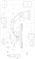
- Figure 1 shows the construction of a metallic part 10 by welding a piece of weldable material onto a first layer by an electric arc welding process that melts a wire consumable of the weldable material using a weld bead layering technique to provide freeform fabrication.
- a computer 12 providing feedback signals A,B,C,D,E for the control of a robot power supply 14, a welder power supply 16, an activating solenoid valve 36, an induction heating apparatus 32 and a solenoid controller 18.
- the welder power supply 16 also provides power and control for a wire feeder 20.
- Wire is fed via F to a welding torch 22 that is a part of the robot 24, which in this form is an electric arc transferred plasma welding torch.
- An electric arc may alternatively be transferred via a tungsten inert gas welding torch, again with a wire feeder 20 of similar weldable material. Further, an electric arc may be transferred via a wire consumable using a gas metal inert welding torch.
- the gas supply system includes a shielding gas feed cylinder 40 supplying an 8/2 solenoid valve 36 to activate the gas going to a purge apparatus 30, via a further solenoid splitter valve 38. Feedback signals provide suitable control via the solenoid controller 18.
- the metallic part 10 being welded in the layer-by-layer process described above is layered on a suitable substrate 26 supported by a substrate cooling bed 28.
- a purge apparatus 30 is positioned above the metallic part 10 to shield the deposited weld in the manner generally described above. Actuators for the robot 24 and the torch, and for the purge apparatus 30, are shown located outside the boundary limits of the build area, the substrate 26, and a high energy heat source 32.
- the substrate 26 and subsequent metal layering is pre-heated and maintained using an induction heating apparatus 32, which is synergic controlled during the metal layering operation. Induction heating during the process enhances increased metal deposition and provides a means of distortion control for the final part 10.
- the substrate 26 in this embodiment includes cooling channels (not shown) to further control the temperature of the metal part 10.
- the cooling apparatus 34 is closed loop in nature and is connected to the substrate via fittings which circulate coolant through the cooling channels. Cooling offers the advantage of decreasing the time between layers, thus decreasing overall build times for a completed 3D printed part.
- This embodiment of the method and apparatus of the invention provides a high deposition method and apparatus for manufacturing 3D metal parts, which includes localised atmospheric protection and solid freeform fabrication unrestricted in size and open to the ambient atmosphere, in particular for the manufacture of parts made of carbon manganese alloys, aluminium alloys, nickel alloys, stainless steels and titanium alloys.
- the apparatus has no restriction to build or part size, or area size, and is open to the ambient atmosphere, wherein the molten weld pool and neighbouring area is shielded by the localised apparatus used for distributing a generous but controlled laminar inert gas flow. Gas flow distribution is located above the build area and given a design such that the gas distribution flows evenly and equally around the weld pool area and solidifying molten metal.
Landscapes
- Engineering & Computer Science (AREA)
- Mechanical Engineering (AREA)
- Physics & Mathematics (AREA)
- Plasma & Fusion (AREA)
- Manufacturing & Machinery (AREA)
- Materials Engineering (AREA)
- Chemical & Material Sciences (AREA)
- Optics & Photonics (AREA)
- Theoretical Computer Science (AREA)
- Electromagnetism (AREA)
- Robotics (AREA)
- Automation & Control Theory (AREA)
- Arc Welding In General (AREA)
- Laser Beam Processing (AREA)
Description
- This invention relates to a method and apparatus for manufacturing weldable metallic objects by solid freeform fabrication.
- Metallic parts, including machine and structural components, that are made from any material type for an engineered use are usually made by casting, forging, rolling and machining from an ingot or billet. These methods are normally disadvantaged by a high percentage of material wastage when finishing the part to its final shape. Additionally, these methods enhance delivery times for the delivery of the completed parts.
- Metallic parts that are completely dense in their physical form can also be manufactured using technologies identified as additive manufacturing, rapid prototyping, rapid manufacturing, layered manufacturing or additive fabrication. This method of manufacture encompasses the use of computer aided design software (CAD) to initially develop a computer-generated model of the part to be manufactured, then to convert the computer-generated model into thin parallel layers which are normally in a horizontal plane. The metallic part is then manufactured by layering successive material in the form of a consumable powder fusing each layer together sequentially until a final shape is formed that resembles the CAD model. This method is also commonly referred to as 3D printing, solid freeform fabrication, rapid prototyping or wire-arc additive manufacturing.
- The method described in the preceding paragraph allows manufacturing of metallic parts of nearly any shape with the advantages of increased production times, depending on the size of each metallic part. The method is normally restricted for prototypes, low volume production and small production runs, but is less suited to large parts and high volume manufacture. Further methods and apparatuses for manufacturing weldable metallic objects by solid freeform fabrication are disclosed in
US 2015/108095 A1 and J.Ding et al: "Development of a laminar flow local shielding device for wire + arc additive manufacture", Journal of Materials Processing Technology, vol. 226, 1 December 2015 (2015-12-01), pages 99-105. - Before turning to a summary of the solution provided by the present invention, it should be appreciated that reference to any prior art in this specification is not, and should not be taken as, an acknowledgment or any form of suggestion that this prior art forms part of the common general knowledge in any country.
- In one aspect, the present invention provides a method of manufacturing a metallic part in a weldable material by solid freeform fabrication unrestricted in size and open to the ambient atmosphere, wherein the method comprises:
- generating a computer-generated, three dimensional model of the part, slicing the computer-generated, three dimensional model into a set of computer-generated, parallel sliced layers and then dividing each layer into a set of computer-generated, virtual, one-dimensional pieces and, with reference to layered weld-bead geometry data, forming a computer-generated, direction specific, layered model of the part,
- uploading the direction specific, layered model of the part into a welding control system able to control the position and activation relative to a support substrate, of an electric arc delivered by a high energy tungsten arc welding torch, a plasma transferred arc welding torch, and/or a gas metal arc welding torch, and a system for feeding a consumable wire placed in an open area build space relevant to the substrate unrestricted in size and open to the ambient atmosphere,
- directing the welding control system to deposit a sequence of one-dimensional weld beads of the weldable material onto the supporting substrate in a pattern required to form a first layer of the computer-generated direction specific layered model of the part,
- depositing a second welded layer by sequencing one-dimensional weld beads of the weldable material onto the previous deposited layer in a configuration the same as the second layer of the computer-generated direction specific layered model of the part, and
- repeating each successive weld bead layer of the computer-generated, direction specific, layered model of the part until the entire part is completed;
- wherein the method further includes:
- displacing the atmosphere within the immediate vicinity of the heat source with an inert gas atmosphere which produces a required flow rate, and in which the inert atmosphere contains a maximum oxygen concentration, wherein the inert gas is delivered by an apparatus through a matrix of individual gas diffusers and/or a filter; and
- engaging an induction heating and closed loop cooling apparatus synergic to a welding control system and pre-heating the substrate material including the deposited weld beads, relevant to the type of weldable material, wherein induction heating and cooling cycles are applied constantly or pulsed from the first layer to the final layer, where optimal heating and/or cooling cycles of the weldable material are relative to the final desired part shape and microstructure.
- In another aspect, the present invention provides a production apparatus for a part made of a weldable material by solid freeform fabrication, where there is no enclosure or reactor required, and the part is built in an unrestricted build environment open to the ambient atmosphere by an apparatus which distributes an inert gas flow, the production apparatus including:
- a robotic multiple-axis mechanism controlling the position and movement of a welding torch with a wire feeder relative to a stationary support substrate placed upon a fixed support, the welding torch being an electric arc welding process, a tungsten arc welding torch, a gas metal arc welding torch, or a plasma transferred arc welding torch;
- a support mechanism controlling the position and movement of the welding torch with the wire feeder relative to the support substrate, with an actuator controlling the position and movement relative to the support mechanism; and
- a control system able to read a computer-generated, three dimensional, direction specific, layered model of the part and employ the computer-generated model to control the position and movement of the robot, and the operation of the welding torch and wire feeder, such that the part is built by welding in a layer-by-layer sequence according to the one-dimensional slices of the weldable material onto the substrate in agreement with the computer-generated, three dimensional, direction specific, layered model of the part;
- the apparatus also including a localised purging apparatus and an induction heating and closed loop cooling apparatus.
- In a preferred form, the required flow rate mentioned above is greater than 20 l/min. In another preferred form, the maximum oxygen concentration mentioned above is less than 500ppm oxygen or alternatively is less than 100ppm oxygen. In yet another preferred form, there are less than 25 of the individual gas diffusers mentioned above.
- The invention thus provides a method and apparatus for increased deposition of manufactured metallic parts in weldable ferrous and non-ferrous metals, including their alloys, which are not restricted to the build size of a part.
- The invention may include localised gas flow distribution in relation to the weld zone and melted metal to minimise surface contamination as an alternative to current practices involving atmospheric oxygen surrounding the weld zone and melted metal.
- The invention may also include controlled heating and cooling through constant or intermittent temperature control using induction heating and a closed loop cooling system, which can be maintained during the build process and provide controlled heating and cooling of the part, additionally reducing distortion and therefore providing some control to distortion of the built part.
- As is apparent from the above, the invention is a method and apparatus for 3D metal printing manufacturing of a part, created from a computer-generated model which includes sliced layers with a finite dimension, in a weldable material by solid freeform fabrication, unrestricted in part size, which utilises (a) a protective inert gas shield that surrounds the electric arc and subsequent cooling molten metal and (b) an induction heating and closed loop cooling apparatus for temperature control of both the substrate and layered 3D printed part during the sequentially layered weld bead operation.
- The use of the protective inert gas shield, which can also be described as a localised inert gas diffuser apparatus, and the induction heating and cooling apparatus, makes it possible to increase volumetric deposition layer by layer for weldable metals, in particular, such as carbon manganese alloys, aluminium alloys, nickel alloys and titanium or titanium alloys and titanium alloy objects.
- The entire build envelope of the 3D printed part may use a similar substrate metal to deposit the initial and subsequent weld bead layers that form the final part, without the need for commissioning an entirely enclosed chamber or using contained sealed protective procedures to avoid oxidising the newly deposited sequential layers of molten weld metal or the associated molten area.
- The computer-generated model of the part may be separated into a set of parallel layered slices with a finite dimension, and each layered slice may be divided into a set of sequential virtual one-dimensional pieces. The term "virtual one-dimensional pieces" as used herein means longitudinal bead resembling pieces of the weld bead material geometry which, when deposited side by side or stacked one upon another in a specific sequential pattern according to the direction specific to the model, will form the part that is to be manufactured. The term "computer-generated direction specific, layered model of the part" as used herein means a three dimensional computerized illustration of the piece which is to be shaped.
- The computer-generated model may comprise dimensional and weld bead geometry data in all directions and be given a three dimensional design which resembles the three dimensional design of the metallic part that is to be manufactured. The computer-generated, direction specific, layered model may then be applied to the freeform fabrication equipment as a template to construct the physical metallic part. That is, the computer-generated model may be transformed into a specific set of instructions implemented by the control system of the solid freeform fabrication equipment such that the metallic part is being manufactured sequentially by welding a wire onto a substrate in sequential lines, where each welded layer corresponds to a slice of the computer-generated, direction specific, layered model. The invention may apply any known or credible software for computer assisted design for creating the computer-generated, direction specific, layered model.
- During the welding of aluminium alloys, stainless steels, nickel or nickel alloys, titanium or titanium alloy or other reactive metal parts, inert gas protection is required to prevent sensitisation or destruction of the protective oxide layer such that this protective layer is oxidised and therefore may affect the final physical and mechanical properties of the final formed part. Therefore, the oxygen surrounding the electric arc and subsequent molten material may be completely displaced by applying a flow of argon or argon mixture gas in a stable continuous mode at predetermined flow-rate settings that give a laminar or any other suitable flow through a series of numerous gas diffuser outlets and/or through a filter such as a sintered bronze filter, in the bottom of a gas manifold compartment, or by any other supply options to the compartment, by typically inserting only the same amount of inert gas as the volume of the compartment and still obtain an oxygen content in the inert argon atmosphere, typically of less than 500ppm oxygen or less than 100ppm oxygen. Typically, the gas manifold compartment may be 80 to 180 mm wide and 180 to 400 mm long, or may be a cylindrical shape of less than 400mm in diameter.
- Gas flow into the gas manifold compartment may be via a manifold located within the purge apparatus and gas flows through the manifold, distributed accordingly through the gas diffuser nozzles and/or the filter which displaces the oxygen in the weld zone. The inlet tube may distribute and control the flow of gas into the manifold via an electronically controlled valve, which has an ability to control the flow rate, pressure and volume of gas continuously or periodically, creating a pulsed delivery of inert gas to the weld zone. This feature of the purge apparatus gives the advantage of using less volumes of costly inert gas.
- The gas manifold compartment may also include a closed cooling circuit where a separate inert gas is passed through a heat-exchanger to lower the temperature of the inert gas flowing through the manifold, and then this gas may be circulated via a recycle distribution loop that flows through the manifold tubes providing the localised shielding to the weld zone. This feature is advantageous to avoid overheating of the localised purge apparatus and to a limited extent also the welding torch.
- A 6-axis or greater robot may be used to control the position and movement of a welding torch with wire feeder for feeding a wire consumable of the weldable material, ideally positioned above the build envelope of the part to be manufactured. The robot may also be governed by the size of the substrate. The localised purge apparatus may be mounted to a bracket arm structure that mounts the welding torch and related wire feeder holding device, which is mechanically attached to the robot. The localised purge apparatus may be equipped with at least closable gas diffuser outlets and at least five closable gas inlets connected to the tube manifold in order to displace oxygen from the weld zone and substitute this gas with a controlled surrounding inert gas. The purge apparatus may incorporate the weld torch device in an interchangeable manner.
- The invention may apply any known or conceivable control system for the operating movement of the electric arc welding torch, localised gas purging apparatus, and wire stock feeder. The operating movement may advantageously be furnished with a six axis robotic control system (X,Y,Z, and three or more rotation axis points). The operating movement may also be in the form of any known or conceivable gantry mounted systems (X,Y,Z) and the mounting table may be stationary or move in the X,Y,Z directions relative to the mounted electric arc welding torch. The invention may apply any known or conceivable welding torch and wire stock feeder system able to perform weld layered manufacturing of metallic parts by the welding processes known as tungsten inert gas welding (GTAW), gas metal arc welding (GMAW) and plasma transferred arc welding (PTAW).
- The induction element for pre-heating the substrate and weld layers may be synergic controlled with the welding and robotic control system. Synergic closed looped control (of the 3 controllers) allows increased temperatures of the substrate and the deposited weld bead layers such that the welding parameters may be altered linearly from pre-set data in a fashion that increases weld bead geometry, therein increasing metal deposition, and therein increasing welding speeds.
- The induction heating apparatus may be any commercially available system, electromagnetic in nature, preferably connected to the substrate where induction is initiated prior to the weld bead layering process. Application of preheating not only increases the weld bead size and deposition speeds but it also reduces distortion and internal residual stresses of the final 3D printed part. This offers an advantage over other known 3D metal printing processes. The application of controlled synergic induction heating relative to the welding process parameters may be enhanced further by known data that optimises the incremental application during the weld bead layering process, so that favourable physical and mechanical properties can be achieved for the final 3D printed part.
- The cooling apparatus may be any commercially available system which is closed loop in nature and is preferably connected to the substrate via inlet and outlet fittings which circulate coolant through cooling channels within the substrate. Flow rates can vary depending on the metallic material type. Application of cooling assists in some cases where the desired mechanical properties of the 3D printed part are enhanced by more rapid cooling. Rapid cooling offers the advantage of decreasing the time between layers, and thus decreasing overall build times.
- The temperature of the physical part during the weld bead layering process may be increased up to the softening point, for any weldable material. For example, in case of 3D metal layering of titanium or its alloys, the temperature may be as high as 800°C during the layered fabrication of the part. However, this will have a corresponding change to the heat source parameters of the electric arc and its delivery of the melted wire, wherein the electric arc parameters enhance the weld bead deposition. Beneficially, this can provide significant reductions in production times for parts manufactured in accordance with the invention.
- One embodiment of the manufacturing method and apparatus of the present invention is shown in the schematic drawing of
Figure 1. Figure 1 shows the construction of ametallic part 10 by welding a piece of weldable material onto a first layer by an electric arc welding process that melts a wire consumable of the weldable material using a weld bead layering technique to provide freeform fabrication. - With reference to
Figure 1 , illustrated is acomputer 12 providing feedback signals A,B,C,D,E for the control of arobot power supply 14, awelder power supply 16, an activatingsolenoid valve 36, aninduction heating apparatus 32 and asolenoid controller 18. Thewelder power supply 16 also provides power and control for awire feeder 20. Wire is fed via F to awelding torch 22 that is a part of therobot 24, which in this form is an electric arc transferred plasma welding torch. An electric arc may alternatively be transferred via a tungsten inert gas welding torch, again with awire feeder 20 of similar weldable material. Further, an electric arc may be transferred via a wire consumable using a gas metal inert welding torch. - The gas supply system includes a shielding
gas feed cylinder 40 supplying an 8/2solenoid valve 36 to activate the gas going to apurge apparatus 30, via a furthersolenoid splitter valve 38. Feedback signals provide suitable control via thesolenoid controller 18. - The
metallic part 10 being welded in the layer-by-layer process described above is layered on asuitable substrate 26 supported by asubstrate cooling bed 28. Apurge apparatus 30 is positioned above themetallic part 10 to shield the deposited weld in the manner generally described above. Actuators for therobot 24 and the torch, and for thepurge apparatus 30, are shown located outside the boundary limits of the build area, thesubstrate 26, and a highenergy heat source 32. - The
substrate 26 and subsequent metal layering is pre-heated and maintained using aninduction heating apparatus 32, which is synergic controlled during the metal layering operation. Induction heating during the process enhances increased metal deposition and provides a means of distortion control for thefinal part 10. - The
substrate 26 in this embodiment includes cooling channels (not shown) to further control the temperature of themetal part 10. Thecooling apparatus 34 is closed loop in nature and is connected to the substrate via fittings which circulate coolant through the cooling channels. Cooling offers the advantage of decreasing the time between layers, thus decreasing overall build times for a completed 3D printed part. - This embodiment of the method and apparatus of the invention provides a high deposition method and apparatus for manufacturing 3D metal parts, which includes localised atmospheric protection and solid freeform fabrication unrestricted in size and open to the ambient atmosphere, in particular for the manufacture of parts made of carbon manganese alloys, aluminium alloys, nickel alloys, stainless steels and titanium alloys.
- As mentioned above, the apparatus has no restriction to build or part size, or area size, and is open to the ambient atmosphere, wherein the molten weld pool and neighbouring area is shielded by the localised apparatus used for distributing a generous but controlled laminar inert gas flow. Gas flow distribution is located above the build area and given a design such that the gas distribution flows evenly and equally around the weld pool area and solidifying molten metal.
- Many modifications may be made to the embodiment of the invention described in relation to
Figure 1 without departing from the scope of the invention, as defined by the appended claims.
Claims (11)
- A method of manufacturing a metallic part in a weldable material by solid freeform fabrication unrestricted in size and open to the ambient atmosphere, wherein the method comprises:generating a computer-generated, three dimensional model of the part, slicing the computer-generated three dimensional model into a set of computer-generated, parallel, sliced layers and then dividing each layer into a set of computer-generated, virtual, one-dimensional pieces and, with reference to layered weld-bead geometry data, forming a computer-generated, direction specific, layered model of the part,uploading the direction specific, layered model of the part into a welding control system able to control the position and activation relative to a support substrate, of an electric arc delivered by a high energy tungsten arc welding torch, a plasma transferred arc welding torch, and/or a gas metal arc welding torch, and a system for feeding a consumable wire placed in an open area build space relevant to the substrate unrestricted in size and open to the ambient atmosphere,directing the welding control system to deposit a sequence of one-dimensional weld beads of the weldable material onto the supporting substrate in a pattern required to form a first layer of the computer-generated, direction specific, layered model of the part,depositing a second welded layer by sequencing one- dimensional weld beads of the weldable material onto the previous deposited layer in a configuration the same as the second layer of the computer-generated direction specific layered model of the part, andrepeating each successive weld bead layer of the computer-generated, direction specific, layered model of the part until the entire part is completed;wherein the method further includes:displacing the atmosphere within the immediate vicinity of the heat source with an inert gas atmosphere which produces a required flow rate, and in which that inert atmosphere contains a maximum oxygen concentration, wherein the inert gas is delivered by an apparatus through a matrix of individual gas diffusers and/or a filter; and is characterized in that it includesengaging an induction heating and closed loop cooling apparatus synergic to a welding control system and pre-heating the substrate material including the deposited weld beads, relevant to the type of weldable material, wherein induction heating and cooling cycles are applied constantly or pulsed from the first layer to the final layer, where optimal heating and/or cooling cycles of the weldable material are relative to the final desired part shape and microstructure.
- A method according to claim 1, wherein the weldable material is a weldable metal, or a weldable alloyed metal, of ferrous or non-ferrous nature.
- A method according to claim 2, wherein the weldable material is carbon steel or carbon manganese alloys, nickel or nickel alloys, stainless steels, aluminium or aluminium alloys, titanium or alloyed titanium, ferrous or non-ferrous, or a mixture of dissimilar weldable materials.
- A method according to any one of claims 1 to 3, wherein the inert gas is one of argon, helium, hydrogen, nitrogen, or a mixture of these.
- A method according to any one of claims 1 to 3, wherein the inert gas shielding the electric arc and heat-affected material is argon or an argon mixture, and where the flow rate of the argon or argon mixture is constant or pulsed and above 20 or 25 liters per minute, and wherein the distribution of the inert gas is delivered through a series of gas diffusers.
- A method according to any one of claims 1 to 5, wherein the required flow rate is greater than 20 l/min.
- A method according to any one of claims 1 to 6, wherein the maximum oxygen concentration is less than 500ppm oxygen or is less than 100ppm oxygen.
- A method according to any one of claims 1 to 7, wherein there are less than 25 individual gas diffusers.
- Production apparatus for a part made of a weldable material by solid freeform fabrication, where there is no enclosure or reactor required, and the part is built in an unrestricted build environment open to the ambient atmosphere by an apparatus which distributes an inert gas flow, the production apparatus including:a robotic multiple-axis mechanism controlling the position and movement of a welding torch with a wire feeder relative to a stationary support substrate placed upon a fixed support, the welding torch being an electric arc welding process, a tungsten arc welding torch, a gas metal arc welding torch, or a plasma transferred arc welding torch;a support mechanism controlling the position and movement of the welding torch and the wire feeder relative to the support substrate an actuator controlling the position and movement relative to the support mechanism; anda control system able to read a computer-generated, three dimensional, direction specific, layered model of the part and employ the computer-generated model to control the position and movement of the robot, and the operation of the welding torch and wire , feeder such that a part is built by welding in a layer-by-layer sequence according to one-dimensional slices of the weldable material onto the substrate structure in agreement with the computer-generated, three dimensional, direction specific, layered model of the part;characterized in that the apparatus also including a localised purging apparatus and an induction heating and closed loop cooling apparatus.
- Apparatus according to claim 9 wherein the localised purging apparatus includes a manifold filled with argon or argon mixture as inert gas and where the gas inlet is equipped with means for regulating the gas flow rate.
- Apparatus according to claim 9 or claim 10 wherein the induction heating apparatus is electrically attached to the substrate and subsequent weld bead layers.
Applications Claiming Priority (2)
| Application Number | Priority Date | Filing Date | Title |
|---|---|---|---|
| AU2018901257A AU2018901257A0 (en) | 2018-04-14 | The invention provides a method and apparatus for increased deposition of manufactured metallic parts in weldable ferrous and non-ferrous metals including their alloys that is not restricted to build size of the part. The invention may include localised gas flow distribution in relation to the weld zone and melted metal; the invention may also include controlled heating and cooling through constant or intermittent temperature control using induction heating. The invention is a method and apparatus for 3D metal printing manufacturing of an object or component. | |
| PCT/AU2019/050269 WO2019195877A1 (en) | 2018-04-14 | 2019-03-26 | Method and apparatus for manufacturing 3d metal parts |
Publications (4)
| Publication Number | Publication Date |
|---|---|
| EP3781344A1 EP3781344A1 (en) | 2021-02-24 |
| EP3781344A4 EP3781344A4 (en) | 2022-01-12 |
| EP3781344B1 true EP3781344B1 (en) | 2023-11-15 |
| EP3781344C0 EP3781344C0 (en) | 2023-11-15 |
Family
ID=68162778
Family Applications (1)
| Application Number | Title | Priority Date | Filing Date |
|---|---|---|---|
| EP19784449.1A Active EP3781344B1 (en) | 2018-04-14 | 2019-03-26 | Method and apparatus for manufacturing 3d metal parts |
Country Status (10)
| Country | Link |
|---|---|
| US (2) | US20210016381A1 (en) |
| EP (1) | EP3781344B1 (en) |
| JP (1) | JP7225501B2 (en) |
| KR (1) | KR102276201B1 (en) |
| AU (1) | AU2019251514B2 (en) |
| ES (1) | ES2964623T3 (en) |
| MY (1) | MY206382A (en) |
| NZ (1) | NZ764390A (en) |
| SG (1) | SG11201909477SA (en) |
| WO (1) | WO2019195877A1 (en) |
Cited By (1)
| Publication number | Priority date | Publication date | Assignee | Title |
|---|---|---|---|---|
| EP4674551A1 (en) * | 2024-07-04 | 2026-01-07 | L'air Liquide, Societe Anonyme Pour L'etude Et L'exploitation Des Procedes Georges Claude | Wire arc additive manufacturing method |
Families Citing this family (18)
| Publication number | Priority date | Publication date | Assignee | Title |
|---|---|---|---|---|
| MX2017007479A (en) | 2014-12-12 | 2018-05-07 | Digital Alloys Incorporated | Additive manufacturing of metallic structures. |
| US20210016381A1 (en) | 2018-04-14 | 2021-01-21 | Aml3D Pty Limited | Method and apparatus for manufacturing 3d metal parts |
| WO2019246308A1 (en) | 2018-06-20 | 2019-12-26 | Digital Alloys Incorporated | Multi-diameter wire feeder |
| WO2020160214A1 (en) | 2019-02-01 | 2020-08-06 | Digital Alloys Incorporated | Systems and methods for three-dimensional printing |
| US11853033B1 (en) | 2019-07-26 | 2023-12-26 | Relativity Space, Inc. | Systems and methods for using wire printing process data to predict material properties and part quality |
| US12365042B2 (en) * | 2021-04-09 | 2025-07-22 | National Oilwell Varco, L.P. | Systems and methods for wire arc additive manufacturing |
| JP7687871B2 (en) * | 2021-06-04 | 2025-06-03 | 清水建設株式会社 | METAL SHAPE MANUFACTURING METHOD AND METAL SHAPE MANUFACTURING APPARATUS |
| CN113909633B (en) * | 2021-10-01 | 2023-07-18 | 江苏烁石焊接科技有限公司 | Synchronous heating stress deformation control system and method for robot arc material-adding shaft parts |
| CN114632946B (en) * | 2022-02-25 | 2024-02-09 | 西安航天发动机有限公司 | Integral manufacturing method of large-size special-shaped section bent pipe type bearing member |
| CN114433980B (en) * | 2022-03-12 | 2024-07-16 | 北京工业大学 | A device and method for controlling molten pool size in arc additive manufacturing process |
| GB2618618B (en) * | 2022-05-13 | 2024-11-27 | Forg3D Ltd | Method and apparatus for manufacturing a metal structure |
| US20230398606A1 (en) * | 2022-06-09 | 2023-12-14 | Relativity Space, Inc. | Printing Heads and Associated Methods |
| EP4374990A1 (en) * | 2022-10-31 | 2024-05-29 | UniTech3DP Inc. | Three-dimensional printing apparatus |
| CN115674674A (en) * | 2022-10-31 | 2023-02-03 | 华东交通大学 | Device is moulded in artistic design 3D molding |
| CN117123891B (en) * | 2023-10-24 | 2024-01-12 | 北京航科精机科技有限公司 | A method and device for repairing parts by adding or subtracting materials based on intelligent control of robotic arms |
| CN117961382B (en) * | 2024-03-28 | 2024-05-28 | 江苏恒久钢构股份有限公司 | A kind of intelligent processing control system for grid rods |
| CN118180556B (en) * | 2024-04-22 | 2024-09-13 | 北京石油化工学院 | Arc additive manufacturing system and method for titanium alloy gradient material |
| CN118268778B (en) * | 2024-05-31 | 2024-07-26 | 广州市柏琳汽车零件制造有限公司 | Efficient welding equipment for automobile air conditioner compressor |
Citations (13)
| Publication number | Priority date | Publication date | Assignee | Title |
|---|---|---|---|---|
| US5233150A (en) | 1991-01-21 | 1993-08-03 | Sulzer Brothers Limited | Method of production of workpieces by welding equipment |
| US6274839B1 (en) | 1998-12-04 | 2001-08-14 | Rolls-Royce Plc | Method and apparatus for building up a workpiece by deposit welding |
| US20070122562A1 (en) | 2005-11-30 | 2007-05-31 | Honeywell International, Inc. | Solid-free-form fabrication process and apparatus including in-process workpiece cooling |
| US20090039062A1 (en) | 2007-08-06 | 2009-02-12 | General Electric Company | Torch brazing process and apparatus therefor |
| US8604381B1 (en) | 2006-10-12 | 2013-12-10 | Purdue Research Foundation | Integrated laser material processing cell |
| US20150108095A1 (en) | 2013-10-18 | 2015-04-23 | +Mfg, LLC | Method and apparatus for fabrication of articles by molten and semi-molten deposition |
| US20160096326A1 (en) | 2014-10-03 | 2016-04-07 | Tyco Electronics Corporation | Selective zone temperature control build plate |
| US9346116B2 (en) | 2009-08-14 | 2016-05-24 | Norsk Titanium As | Method and device for manufacturing titanium objects |
| US20160271732A1 (en) | 2015-03-19 | 2016-09-22 | Dm3D Technology, Llc | Method of high rate direct material deposition |
| CN106141373A (en) * | 2016-07-18 | 2016-11-23 | 南京航空航天大学 | The electric arc 3D printing device of aluminum alloy junction component and Method of printing |
| WO2017103849A1 (en) | 2015-12-18 | 2017-06-22 | Czech Technical University In Prague, Faculty Of Mechanical Engineering, Department Of Production Machines And Equipment | Method of creating metal components using the deposition of material and apparatus to implement this method |
| US20180345649A1 (en) | 2017-06-05 | 2018-12-06 | The Boeing Company | Multi-region temperature controlled base for additive manufacturing |
| WO2019195877A1 (en) | 2018-04-14 | 2019-10-17 | Aml3D Pty Ltd | Method and apparatus for manufacturing 3d metal parts |
Family Cites Families (18)
| Publication number | Priority date | Publication date | Assignee | Title |
|---|---|---|---|---|
| US4814236A (en) * | 1987-06-22 | 1989-03-21 | Westinghouse Electric Corp. | Hardsurfaced power-generating turbine components and method of hardsurfacing metal substrates using a buttering layer |
| US4903888A (en) * | 1988-05-05 | 1990-02-27 | Westinghouse Electric Corp. | Turbine system having more failure resistant rotors and repair welding of low alloy ferrous turbine components by controlled weld build-up |
| JP2649553B2 (en) * | 1988-08-18 | 1997-09-03 | 日鉄ハード株式会社 | High temperature overlay welding method |
| US5207371A (en) * | 1991-07-29 | 1993-05-04 | Prinz Fritz B | Method and apparatus for fabrication of three-dimensional metal articles by weld deposition |
| CA2265215C (en) * | 1998-04-02 | 2004-06-22 | Lincoln Global, Inc. | Welding monitoring system |
| US6375895B1 (en) * | 2000-06-14 | 2002-04-23 | Att Technology, Ltd. | Hardfacing alloy, methods, and products |
| US6572807B1 (en) * | 2000-10-26 | 2003-06-03 | 3D Systems, Inc. | Method of improving surfaces in selective deposition modeling |
| KR101309641B1 (en) * | 2011-11-02 | 2013-09-17 | 재단법인 포항산업과학연구원 | Device and method for welding pipe |
| US10543549B2 (en) * | 2013-07-16 | 2020-01-28 | Illinois Tool Works Inc. | Additive manufacturing system for joining and surface overlay |
| CN105848769B (en) * | 2013-07-31 | 2017-11-17 | 新加坡美能材料科技有限公司 | Adjustable pulse gas agitator |
| EP3096905B1 (en) * | 2014-01-20 | 2021-12-22 | Raytheon Technologies Corporation | A method of additive manufacturing utilizing an epitaxy process |
| US9950476B2 (en) * | 2014-06-05 | 2018-04-24 | The Boeing Company | Distortion prediction and minimisation in additive manufacturing |
| US10816491B2 (en) * | 2015-10-09 | 2020-10-27 | Amir Khajepour | System and method for real time closed-loop monitoring and control of material properties in thermal material processing |
| US20170145586A1 (en) * | 2015-11-23 | 2017-05-25 | Hobart Brothers Company | System and method for single crystal growth with additive manufacturing |
| US20170173694A1 (en) * | 2015-12-16 | 2017-06-22 | Desktop Metal, Inc. | Bulk metallic glass printer with shearing engine in feed path |
| US10738378B2 (en) * | 2016-07-08 | 2020-08-11 | Norsk Titanium As | Multi-chamber deposition equipment for solid free form fabrication |
| JP6289713B1 (en) * | 2017-06-12 | 2018-03-07 | 南海鋼材株式会社 | Welding system and welding method |
| JP6962622B2 (en) * | 2017-11-10 | 2021-11-05 | ゼネラル・エレクトリック・カンパニイ | Gas flow system for additive manufacturing equipment |
-
2019
- 2019-03-26 US US16/624,185 patent/US20210016381A1/en not_active Abandoned
- 2019-03-26 KR KR1020207017029A patent/KR102276201B1/en active Active
- 2019-03-26 SG SG11201909477S patent/SG11201909477SA/en unknown
- 2019-03-26 JP JP2020531121A patent/JP7225501B2/en active Active
- 2019-03-26 ES ES19784449T patent/ES2964623T3/en active Active
- 2019-03-26 EP EP19784449.1A patent/EP3781344B1/en active Active
- 2019-03-26 NZ NZ764390A patent/NZ764390A/en unknown
- 2019-03-26 WO PCT/AU2019/050269 patent/WO2019195877A1/en not_active Ceased
- 2019-03-26 AU AU2019251514A patent/AU2019251514B2/en active Active
- 2019-03-26 MY MYPI2020002399A patent/MY206382A/en unknown
-
2022
- 2022-12-16 US US18/083,382 patent/US20230144822A1/en active Pending
Patent Citations (13)
| Publication number | Priority date | Publication date | Assignee | Title |
|---|---|---|---|---|
| US5233150A (en) | 1991-01-21 | 1993-08-03 | Sulzer Brothers Limited | Method of production of workpieces by welding equipment |
| US6274839B1 (en) | 1998-12-04 | 2001-08-14 | Rolls-Royce Plc | Method and apparatus for building up a workpiece by deposit welding |
| US20070122562A1 (en) | 2005-11-30 | 2007-05-31 | Honeywell International, Inc. | Solid-free-form fabrication process and apparatus including in-process workpiece cooling |
| US8604381B1 (en) | 2006-10-12 | 2013-12-10 | Purdue Research Foundation | Integrated laser material processing cell |
| US20090039062A1 (en) | 2007-08-06 | 2009-02-12 | General Electric Company | Torch brazing process and apparatus therefor |
| US9346116B2 (en) | 2009-08-14 | 2016-05-24 | Norsk Titanium As | Method and device for manufacturing titanium objects |
| US20150108095A1 (en) | 2013-10-18 | 2015-04-23 | +Mfg, LLC | Method and apparatus for fabrication of articles by molten and semi-molten deposition |
| US20160096326A1 (en) | 2014-10-03 | 2016-04-07 | Tyco Electronics Corporation | Selective zone temperature control build plate |
| US20160271732A1 (en) | 2015-03-19 | 2016-09-22 | Dm3D Technology, Llc | Method of high rate direct material deposition |
| WO2017103849A1 (en) | 2015-12-18 | 2017-06-22 | Czech Technical University In Prague, Faculty Of Mechanical Engineering, Department Of Production Machines And Equipment | Method of creating metal components using the deposition of material and apparatus to implement this method |
| CN106141373A (en) * | 2016-07-18 | 2016-11-23 | 南京航空航天大学 | The electric arc 3D printing device of aluminum alloy junction component and Method of printing |
| US20180345649A1 (en) | 2017-06-05 | 2018-12-06 | The Boeing Company | Multi-region temperature controlled base for additive manufacturing |
| WO2019195877A1 (en) | 2018-04-14 | 2019-10-17 | Aml3D Pty Ltd | Method and apparatus for manufacturing 3d metal parts |
Non-Patent Citations (17)
| Title |
|---|
| ADNAN A UGLA, OGUZHAN YILMAZ, AHMED RJ ALMUSAWI: "Development and control of shaped metal deposition process using tungsten inert gas arc heat source in additive layered manufacturing", INSTITUTION OF MECHANICAL ENGINEERS, vol. 232, no. 9, 1 July 2018 (2018-07-01), GB , pages 1628 - 1641, XP055644646, ISSN: 0954-4054, DOI: 10.1177/0954405416673112 |
| AKBARI MEYSAM, DING YAOYU, KOVACEVIC RADOVAN,: "Process development for a robotized laser wire additive manufacturing", PROCEEDINGS OF THE ASME 2017 12TH INTERNATIONAL MANUFACTURING SCIENCE AND ENGINEERING CONFERENCE(MSEC2017), LOS ANGELES, CA, USA, 1 January 2017 (2017-01-01), Los Angeles, CA, USA, pages 1 - 11, XP093208895 |
| AML3D: "AML Layer 5 - View A", YOUTUBE, 17 September 2018 (2018-09-17), pages 1 - 2, XP093208888, Retrieved from the Internet <URL:https://www.youtube.com/watch?v=h4sq43PVNP0> [retrieved on 20240926] |
| AML3D: "AML Layer 5 - View B", YOUTUBE, 17 September 2018 (2018-09-17), pages 1 - 2, XP093208890, Retrieved from the Internet <URL:https://www.youtube.com/watch?v=TzglES4nyO8> [retrieved on 20240926] |
| BAI XINGWANG; ZHANG HAIOU; WANG GUILAN: "Modeling of the moving induction heating used as secondary heat source in weld-based additive manufacturing", THE INTERNATIONAL JOURNAL OF ADVANCED MANUFACTURING TECHNOLOGY, vol. 77, no. 1, 22 October 2014 (2014-10-22), London , pages 717 - 727, XP035458006, ISSN: 0268-3768, DOI: 10.1007/s00170-014-6475-2 |
| CUNNINGHAM C.R., FLYNN J.M., SHOKRANI A., DHOKIA V., NEWMAN S.T.: "Invited review article: Strategies and processes for high quality wire arc additive manufacturing", ADDITIVE MANUFACTURING, vol. 22, 1 August 2018 (2018-08-01), NL , pages 672 - 686, XP093208882, ISSN: 2214-8604, DOI: 10.1016/j.addma.2018.06.020 |
| DING DONGHONG; PAN ZENGXI; CUIURI DOMINIC; LI HUIJUN: "Wire-feed additive manufacturing of metal components: technologies, developments and future interests", THE INTERNATIONAL JOURNAL OF ADVANCED MANUFACTURING TECHNOLOGY, vol. 81, no. 1, 9 May 2015 (2015-05-09), London , pages 465 - 481, XP035536658, ISSN: 0268-3768, DOI: 10.1007/s00170-015-7077-3 |
| HASCOET J.Y., KARUNAKARAN K.P., MARYA S.: "Additive Manufacturing Viewed from Material Science: State of the Art & Fundamentals", MATERIALS SCIENCE FORUM, vol. 783-786, 1 January 2014 (2014-01-01), CH , pages 2284 - 2289, XP093208878, ISSN: 1662-9752, DOI: 10.4028/www.scientific.net/MSF.783-786.2284 |
| I GIBSON , D. W. ROSEN , B. STUCKER: "Additive Manufacturing Technologies, Rapid Prototyping to Direct Digital Manufacturing", 1 January 2010, SPRINGER , ISBN: 978-1-4419-1119-3, article GIBSON, IAN; ROSEN, DAVID ; STUCKER, BRENT: "Table of contents", pages: 1 - 10, XP009559610 |
| J. DING ET AL: "Development of a laminar flow local shielding device for wire + arc additive manufacture", JOURNAL OF MATERIALS PROCESSING TECHNOLOGY, vol. 226, 1 December 2015 (2015-12-01), NL, pages 99 - 105, XP055674206, ISSN: 0924-0136, DOI: 10.1016/j.jmatprotec.2015.07.005 * |
| J. DING, P. COLEGROVE, F. MARTINA, S. WILLIAMS, R. WIKTOROWICZ, M.R. PALT: "Development of a laminar flow local shielding device for wire + arc additive manufacture", JOURNAL OF MATERIALS PROCESSING TECHNOLOGY, vol. 226, 1 December 2015 (2015-12-01), NL , pages 99 - 105, XP055674206, ISSN: 0924-0136, DOI: 10.1016/j.jmatprotec.2015.07.005 |
| LU X.; ZHOU Y. F.; XING X. L.; SHAO L. Y.; YANG Q. X.; GAO S. Y.: "Open-source wire and arc additive manufacturing system: formability, microstructures, and mechanical properties", THE INTERNATIONAL JOURNAL OF ADVANCED MANUFACTURING TECHNOLOGY, vol. 93, no. 5, 27 June 2017 (2017-06-27), London , pages 2145 - 2154, XP036339816, ISSN: 0268-3768, DOI: 10.1007/s00170-017-0636-z |
| WU BINTAO; PAN ZENGXI; DING DONGHONG; CUIURI DOMINIC; LI HUIJUN; FEI ZHENYU: "The effects of forced interpass cooling on the material properties of wire arc additively manufactured Ti6Al4V alloy", JOURNAL OF MATERIALS PROCESSING TECHNOLOGY, vol. 258, 27 March 2018 (2018-03-27), NL , pages 97 - 105, XP085384452, ISSN: 0924-0136, DOI: 10.1016/j.jmatprotec.2018.03.024 |
| XIONG JUN ET AL: "Finite element analysis and experimental validation of thermal behavior for thin-walled parts in GMAW-based additive manufacturing with various substrate preheating temperatures", APPLIED THERMAL ENGINEERING, PERGAMON, OXFORD, GB, vol. 126, 22 July 2017 (2017-07-22), pages 43 - 52, XP085198133, ISSN: 1359-4311, DOI: 10.1016/J.APPLTHERMALENG.2017.07.168 * |
| XIONG JUN; LEI YANGYANG; LI RONG: "Finite element analysis and experimental validation of thermal behavior for thin-walled parts in GMAW-based additive manufacturing with various substrate preheating temperatures", APPLIED THERMAL ENGINEERING, vol. 126, 22 July 2017 (2017-07-22), GB , pages 43 - 52, XP085198133, ISSN: 1359-4311, DOI: 10.1016/j.applthermaleng.2017.07.168 |
| XU XIANGFANG ET AL: "Oxide accumulation effects on wire+arc layer-by-layer additive manufacture process", JOURNAL OF MATERIALS PROCESSING TECHNOLOGY, vol. 252, 20 October 2017 (2017-10-20), pages 739 - 750, XP085260279, ISSN: 0924-0136, DOI: 10.1016/J.JMATPROTEC.2017.10.030 * |
| XU XIANGFANG; DING JIALUO; GANGULY SUPRIYO; DIAO CHENGLEI; WILLIAMS STEWART: "Oxide accumulation effects on wire+arc layer-by-layer additive manufacture process", JOURNAL OF MATERIALS PROCESSING TECHNOLOGY, vol. 252, 20 October 2017 (2017-10-20), NL , pages 739 - 750, XP085260279, ISSN: 0924-0136, DOI: 10.1016/j.jmatprotec.2017.10.030 |
Cited By (1)
| Publication number | Priority date | Publication date | Assignee | Title |
|---|---|---|---|---|
| EP4674551A1 (en) * | 2024-07-04 | 2026-01-07 | L'air Liquide, Societe Anonyme Pour L'etude Et L'exploitation Des Procedes Georges Claude | Wire arc additive manufacturing method |
Also Published As
| Publication number | Publication date |
|---|---|
| MY206382A (en) | 2024-12-13 |
| EP3781344A1 (en) | 2021-02-24 |
| JP2021518811A (en) | 2021-08-05 |
| ES2964623T3 (en) | 2024-04-08 |
| US20230144822A1 (en) | 2023-05-11 |
| US20210016381A1 (en) | 2021-01-21 |
| KR20200135281A (en) | 2020-12-02 |
| SG11201909477SA (en) | 2019-11-28 |
| NZ764390A (en) | 2021-07-30 |
| EP3781344C0 (en) | 2023-11-15 |
| JP7225501B2 (en) | 2023-02-21 |
| KR102276201B1 (en) | 2021-07-14 |
| AU2019251514B2 (en) | 2021-02-25 |
| AU2019251514A1 (en) | 2020-05-28 |
| WO2019195877A1 (en) | 2019-10-17 |
Similar Documents
| Publication | Publication Date | Title |
|---|---|---|
| US20230144822A1 (en) | Method and apparatus for manufacturing 3d metal parts | |
| CN109689267B (en) | Method and apparatus for building metal objects by solid freeform fabrication with two welding torches | |
| JP6211156B2 (en) | System for constructing metal object by three-dimensional free-form fabrication method and method for producing three-dimensional object of metal material by three-dimensional free-form fabrication method | |
| US7326377B2 (en) | Solid-free-form fabrication process and apparatus including in-process workpiece cooling | |
| EP3078483B1 (en) | Deposition head for additive manufacturing | |
| JPWO2019195877A5 (en) | ||
| US20070122560A1 (en) | Solid-free-form fabrication process including in-process component deformation | |
| EP3766604A1 (en) | Method and device for purging an additive manufacturing space | |
| US20220176484A1 (en) | Method and arrangement for building metallic objects by solid freeform fabrication | |
| Kumar et al. | Direct energy deposition | |
| US7342195B2 (en) | Customizable ion fusion formation system and process | |
| JP7181154B2 (en) | Laminate-molded article manufacturing method | |
| EP3569342B1 (en) | Process for the layer-by-layer manufactur of parts in ti6al4v by means of coxial arc welding technologies | |
| Mwema et al. | Metal-Arc welding technologies for additive manufacturing of metals and composites | |
| KR20190039071A (en) | Fluid-cooled contact tip assembly for metal welding | |
| Pandey et al. | Manufacturing of Large Metallic Components through Wire and Arc Additive Manufacturing (WAAM) | |
| Galván et al. | Plasma Metal Deposition for | |
| EP4194134A1 (en) | Method and device for removing impurities from a feedstock wire | |
| Tomar et al. | Wire-fed arc-based additive manufacturing techniques and their recent advances | |
| Squires | Wire-Based Directed Energy Deposition: Analysis of Inconel 718, Thermal Dissipation, and Bimetallic Radial Arrangements | |
| US20220258266A1 (en) | Method and apparatus for fabrication of articles by molten and semi-molten deposition | |
| Ferik et al. | Wire arc additive manufacturing: Processes and materials | |
| Pan et al. | Manufacturing: A Review |
Legal Events
| Date | Code | Title | Description |
|---|---|---|---|
| STAA | Information on the status of an ep patent application or granted ep patent |
Free format text: STATUS: THE INTERNATIONAL PUBLICATION HAS BEEN MADE |
|
| TPAC | Observations filed by third parties |
Free format text: ORIGINAL CODE: EPIDOSNTIPA |
|
| PUAI | Public reference made under article 153(3) epc to a published international application that has entered the european phase |
Free format text: ORIGINAL CODE: 0009012 |
|
| STAA | Information on the status of an ep patent application or granted ep patent |
Free format text: STATUS: REQUEST FOR EXAMINATION WAS MADE |
|
| 17P | Request for examination filed |
Effective date: 20201021 |
|
| AK | Designated contracting states |
Kind code of ref document: A1 Designated state(s): AL AT BE BG CH CY CZ DE DK EE ES FI FR GB GR HR HU IE IS IT LI LT LU LV MC MK MT NL NO PL PT RO RS SE SI SK SM TR |
|
| AX | Request for extension of the european patent |
Extension state: BA ME |
|
| REG | Reference to a national code |
Ref country code: HK Ref legal event code: DE Ref document number: 40036956 Country of ref document: HK |
|
| DAV | Request for validation of the european patent (deleted) | ||
| DAX | Request for extension of the european patent (deleted) | ||
| A4 | Supplementary search report drawn up and despatched |
Effective date: 20211215 |
|
| RIC1 | Information provided on ipc code assigned before grant |
Ipc: B33Y 40/20 20200101ALI20211209BHEP Ipc: B23K 37/00 20060101ALI20211209BHEP Ipc: B23K 9/16 20060101ALI20211209BHEP Ipc: B23K 9/04 20060101ALI20211209BHEP Ipc: B22F 12/20 20210101ALI20211209BHEP Ipc: B22F 12/17 20210101ALI20211209BHEP Ipc: B22F 10/50 20210101ALI20211209BHEP Ipc: B22F 10/322 20210101ALI20211209BHEP Ipc: B22F 10/22 20210101ALI20211209BHEP Ipc: B33Y 50/00 20150101ALI20211209BHEP Ipc: B33Y 30/00 20150101ALI20211209BHEP Ipc: B33Y 10/00 20150101ALI20211209BHEP Ipc: B23K 9/00 20060101AFI20211209BHEP |
|
| STAA | Information on the status of an ep patent application or granted ep patent |
Free format text: STATUS: EXAMINATION IS IN PROGRESS |
|
| 17Q | First examination report despatched |
Effective date: 20221205 |
|
| GRAP | Despatch of communication of intention to grant a patent |
Free format text: ORIGINAL CODE: EPIDOSNIGR1 |
|
| STAA | Information on the status of an ep patent application or granted ep patent |
Free format text: STATUS: GRANT OF PATENT IS INTENDED |
|
| INTG | Intention to grant announced |
Effective date: 20230706 |
|
| GRAS | Grant fee paid |
Free format text: ORIGINAL CODE: EPIDOSNIGR3 |
|
| GRAA | (expected) grant |
Free format text: ORIGINAL CODE: 0009210 |
|
| STAA | Information on the status of an ep patent application or granted ep patent |
Free format text: STATUS: THE PATENT HAS BEEN GRANTED |
|
| AK | Designated contracting states |
Kind code of ref document: B1 Designated state(s): AL AT BE BG CH CY CZ DE DK EE ES FI FR GB GR HR HU IE IS IT LI LT LU LV MC MK MT NL NO PL PT RO RS SE SI SK SM TR |
|
| REG | Reference to a national code |
Ref country code: CH Ref legal event code: EP Ref country code: GB Ref legal event code: FG4D |
|
| REG | Reference to a national code |
Ref country code: DE Ref legal event code: R096 Ref document number: 602019041559 Country of ref document: DE |
|
| REG | Reference to a national code |
Ref country code: IE Ref legal event code: FG4D |
|
| U01 | Request for unitary effect filed |
Effective date: 20231213 |
|
| U07 | Unitary effect registered |
Designated state(s): AT BE BG DE DK EE FI FR IT LT LU LV MT NL PT SE SI Effective date: 20231219 |
|
| REG | Reference to a national code |
Ref country code: NO Ref legal event code: T2 Effective date: 20231115 |
|
| PG25 | Lapsed in a contracting state [announced via postgrant information from national office to epo] |
Ref country code: GR Free format text: LAPSE BECAUSE OF FAILURE TO SUBMIT A TRANSLATION OF THE DESCRIPTION OR TO PAY THE FEE WITHIN THE PRESCRIBED TIME-LIMIT Effective date: 20240216 |
|
| REG | Reference to a national code |
Ref country code: ES Ref legal event code: FG2A Ref document number: 2964623 Country of ref document: ES Kind code of ref document: T3 Effective date: 20240408 |
|
| PG25 | Lapsed in a contracting state [announced via postgrant information from national office to epo] |
Ref country code: IS Free format text: LAPSE BECAUSE OF FAILURE TO SUBMIT A TRANSLATION OF THE DESCRIPTION OR TO PAY THE FEE WITHIN THE PRESCRIBED TIME-LIMIT Effective date: 20240315 |
|
| U20 | Renewal fee for the european patent with unitary effect paid |
Year of fee payment: 6 Effective date: 20240321 |
|
| PG25 | Lapsed in a contracting state [announced via postgrant information from national office to epo] |
Ref country code: IS Free format text: LAPSE BECAUSE OF FAILURE TO SUBMIT A TRANSLATION OF THE DESCRIPTION OR TO PAY THE FEE WITHIN THE PRESCRIBED TIME-LIMIT Effective date: 20240315 Ref country code: GR Free format text: LAPSE BECAUSE OF FAILURE TO SUBMIT A TRANSLATION OF THE DESCRIPTION OR TO PAY THE FEE WITHIN THE PRESCRIBED TIME-LIMIT Effective date: 20240216 |
|
| PG25 | Lapsed in a contracting state [announced via postgrant information from national office to epo] |
Ref country code: RS Free format text: LAPSE BECAUSE OF FAILURE TO SUBMIT A TRANSLATION OF THE DESCRIPTION OR TO PAY THE FEE WITHIN THE PRESCRIBED TIME-LIMIT Effective date: 20231115 Ref country code: PL Free format text: LAPSE BECAUSE OF FAILURE TO SUBMIT A TRANSLATION OF THE DESCRIPTION OR TO PAY THE FEE WITHIN THE PRESCRIBED TIME-LIMIT Effective date: 20231115 Ref country code: HR Free format text: LAPSE BECAUSE OF FAILURE TO SUBMIT A TRANSLATION OF THE DESCRIPTION OR TO PAY THE FEE WITHIN THE PRESCRIBED TIME-LIMIT Effective date: 20231115 |
|
| PG25 | Lapsed in a contracting state [announced via postgrant information from national office to epo] |
Ref country code: CZ Free format text: LAPSE BECAUSE OF FAILURE TO SUBMIT A TRANSLATION OF THE DESCRIPTION OR TO PAY THE FEE WITHIN THE PRESCRIBED TIME-LIMIT Effective date: 20231115 |
|
| PG25 | Lapsed in a contracting state [announced via postgrant information from national office to epo] |
Ref country code: SK Free format text: LAPSE BECAUSE OF FAILURE TO SUBMIT A TRANSLATION OF THE DESCRIPTION OR TO PAY THE FEE WITHIN THE PRESCRIBED TIME-LIMIT Effective date: 20231115 |
|
| PG25 | Lapsed in a contracting state [announced via postgrant information from national office to epo] |
Ref country code: SM Free format text: LAPSE BECAUSE OF FAILURE TO SUBMIT A TRANSLATION OF THE DESCRIPTION OR TO PAY THE FEE WITHIN THE PRESCRIBED TIME-LIMIT Effective date: 20231115 Ref country code: SK Free format text: LAPSE BECAUSE OF FAILURE TO SUBMIT A TRANSLATION OF THE DESCRIPTION OR TO PAY THE FEE WITHIN THE PRESCRIBED TIME-LIMIT Effective date: 20231115 Ref country code: RO Free format text: LAPSE BECAUSE OF FAILURE TO SUBMIT A TRANSLATION OF THE DESCRIPTION OR TO PAY THE FEE WITHIN THE PRESCRIBED TIME-LIMIT Effective date: 20231115 Ref country code: CZ Free format text: LAPSE BECAUSE OF FAILURE TO SUBMIT A TRANSLATION OF THE DESCRIPTION OR TO PAY THE FEE WITHIN THE PRESCRIBED TIME-LIMIT Effective date: 20231115 |
|
| REG | Reference to a national code |
Ref country code: DE Ref legal event code: R026 Ref document number: 602019041559 Country of ref document: DE |
|
| PLBI | Opposition filed |
Free format text: ORIGINAL CODE: 0009260 |
|
| PLAX | Notice of opposition and request to file observation + time limit sent |
Free format text: ORIGINAL CODE: EPIDOSNOBS2 |
|
| 26 | Opposition filed |
Opponent name: GEFERTEC GMBH Effective date: 20240814 |
|
| REG | Reference to a national code |
Ref country code: CH Ref legal event code: PL |
|
| PG25 | Lapsed in a contracting state [announced via postgrant information from national office to epo] |
Ref country code: MC Free format text: LAPSE BECAUSE OF FAILURE TO SUBMIT A TRANSLATION OF THE DESCRIPTION OR TO PAY THE FEE WITHIN THE PRESCRIBED TIME-LIMIT Effective date: 20231115 |
|
| PG25 | Lapsed in a contracting state [announced via postgrant information from national office to epo] |
Ref country code: MC Free format text: LAPSE BECAUSE OF FAILURE TO SUBMIT A TRANSLATION OF THE DESCRIPTION OR TO PAY THE FEE WITHIN THE PRESCRIBED TIME-LIMIT Effective date: 20231115 |
|
| PLBB | Reply of patent proprietor to notice(s) of opposition received |
Free format text: ORIGINAL CODE: EPIDOSNOBS3 |
|
| PG25 | Lapsed in a contracting state [announced via postgrant information from national office to epo] |
Ref country code: CH Free format text: LAPSE BECAUSE OF NON-PAYMENT OF DUE FEES Effective date: 20240331 |
|
| PLAB | Opposition data, opponent's data or that of the opponent's representative modified |
Free format text: ORIGINAL CODE: 0009299OPPO |
|
| PGFP | Annual fee paid to national office [announced via postgrant information from national office to epo] |
Ref country code: IE Payment date: 20250318 Year of fee payment: 7 |
|
| U20 | Renewal fee for the european patent with unitary effect paid |
Year of fee payment: 7 Effective date: 20250317 |
|
| PGFP | Annual fee paid to national office [announced via postgrant information from national office to epo] |
Ref country code: GB Payment date: 20250318 Year of fee payment: 7 |
|
| R26 | Opposition filed (corrected) |
Opponent name: GEFERTEC GMBH Effective date: 20240814 |
|
| PGFP | Annual fee paid to national office [announced via postgrant information from national office to epo] |
Ref country code: ES Payment date: 20250606 Year of fee payment: 7 |
|
| PG25 | Lapsed in a contracting state [announced via postgrant information from national office to epo] |
Ref country code: CY Free format text: LAPSE BECAUSE OF FAILURE TO SUBMIT A TRANSLATION OF THE DESCRIPTION OR TO PAY THE FEE WITHIN THE PRESCRIBED TIME-LIMIT; INVALID AB INITIO Effective date: 20190326 |
|
| PG25 | Lapsed in a contracting state [announced via postgrant information from national office to epo] |
Ref country code: HU Free format text: LAPSE BECAUSE OF FAILURE TO SUBMIT A TRANSLATION OF THE DESCRIPTION OR TO PAY THE FEE WITHIN THE PRESCRIBED TIME-LIMIT; INVALID AB INITIO Effective date: 20190326 |
|
| PG25 | Lapsed in a contracting state [announced via postgrant information from national office to epo] |
Ref country code: TR Free format text: LAPSE BECAUSE OF FAILURE TO SUBMIT A TRANSLATION OF THE DESCRIPTION OR TO PAY THE FEE WITHIN THE PRESCRIBED TIME-LIMIT Effective date: 20231115 |
|
| PGFP | Annual fee paid to national office [announced via postgrant information from national office to epo] |
Ref country code: NO Payment date: 20251208 Year of fee payment: 8 |
|
| REG | Reference to a national code |
Ref country code: CH Ref legal event code: Y10 Free format text: ST27 STATUS EVENT CODE: U-0-0-Y10-Y00 (AS PROVIDED BY THE NATIONAL OFFICE) Effective date: 20260128 |