EP3780695A1 - Method and device for obtaining cell information - Google Patents
Method and device for obtaining cell information Download PDFInfo
- Publication number
- EP3780695A1 EP3780695A1 EP19775957.4A EP19775957A EP3780695A1 EP 3780695 A1 EP3780695 A1 EP 3780695A1 EP 19775957 A EP19775957 A EP 19775957A EP 3780695 A1 EP3780695 A1 EP 3780695A1
- Authority
- EP
- European Patent Office
- Prior art keywords
- target
- user equipment
- information
- cell
- frequency
- Prior art date
- Legal status (The legal status is an assumption and is not a legal conclusion. Google has not performed a legal analysis and makes no representation as to the accuracy of the status listed.)
- Granted
Links
Images

Classifications
-
- H—ELECTRICITY
- H04—ELECTRIC COMMUNICATION TECHNIQUE
- H04W—WIRELESS COMMUNICATION NETWORKS
- H04W24/00—Supervisory, monitoring or testing arrangements
- H04W24/02—Arrangements for optimising operational condition
-
- H—ELECTRICITY
- H04—ELECTRIC COMMUNICATION TECHNIQUE
- H04W—WIRELESS COMMUNICATION NETWORKS
- H04W36/00—Hand-off or reselection arrangements
- H04W36/0005—Control or signalling for completing the hand-off
- H04W36/0055—Transmission or use of information for re-establishing the radio link
- H04W36/0058—Transmission of hand-off measurement information, e.g. measurement reports
-
- H—ELECTRICITY
- H04—ELECTRIC COMMUNICATION TECHNIQUE
- H04W—WIRELESS COMMUNICATION NETWORKS
- H04W36/00—Hand-off or reselection arrangements
- H04W36/0005—Control or signalling for completing the hand-off
- H04W36/0055—Transmission or use of information for re-establishing the radio link
- H04W36/0061—Transmission or use of information for re-establishing the radio link of neighbour cell information
-
- H—ELECTRICITY
- H04—ELECTRIC COMMUNICATION TECHNIQUE
- H04W—WIRELESS COMMUNICATION NETWORKS
- H04W36/00—Hand-off or reselection arrangements
- H04W36/0005—Control or signalling for completing the hand-off
- H04W36/0083—Determination of parameters used for hand-off, e.g. generation or modification of neighbour cell lists
- H04W36/0085—Hand-off measurements
- H04W36/0088—Scheduling hand-off measurements
-
- H—ELECTRICITY
- H04—ELECTRIC COMMUNICATION TECHNIQUE
- H04W—WIRELESS COMMUNICATION NETWORKS
- H04W36/00—Hand-off or reselection arrangements
- H04W36/04—Reselecting a cell layer in multi-layered cells
-
- H—ELECTRICITY
- H04—ELECTRIC COMMUNICATION TECHNIQUE
- H04W—WIRELESS COMMUNICATION NETWORKS
- H04W56/00—Synchronisation arrangements
- H04W56/001—Synchronization between nodes
-
- H—ELECTRICITY
- H04—ELECTRIC COMMUNICATION TECHNIQUE
- H04W—WIRELESS COMMUNICATION NETWORKS
- H04W72/00—Local resource management
- H04W72/04—Wireless resource allocation
-
- H—ELECTRICITY
- H04—ELECTRIC COMMUNICATION TECHNIQUE
- H04W—WIRELESS COMMUNICATION NETWORKS
- H04W24/00—Supervisory, monitoring or testing arrangements
- H04W24/10—Scheduling measurement reports ; Arrangements for measurement reports
Definitions
- the present application relates to the field of communications technology, and in particular to a method and device for obtaining cell information.
- a network device in order to perform handover and interference coordination, a network device (for example, eNB) needs to establish and maintain a neighbor relation table for cells under the network device.
- Automatic neighbor relation Automatic Neighbor Relation, ANR
- ANR Automatic Neighbor Relation
- the automatic neighbor relation mechanism is not only suitable for discovering intra-frequency neighbor cells, but also for discovering inter-frequency neighbor cells.
- the user equipment after a user equipment receives ANR measurement configuration issued by the network device, the user equipment starts a timer T321.
- a timing duration of the timer T321 is set based on the radio access technology (Radio Access Technology, RAT), and different RATs are corresponding to different timing durations.
- Radio Access Technology, RAT Radio Access Technology
- the frequency of the NR system is divided into multiple frequency ranges. Different frequency ranges vary greatly in frequency bandwidth, subcarrier spacing, etc., and capabilities of user equipment also vary greatly. If the method of setting the timing duration of the timer based on the RAT in the related art is adopted, the timing duration of the timer may be set unreasonably, which will affect obtaining of cell information and affecting effectiveness of communication.
- An object of embodiments of the present disclosure is to provide a method and device for obtaining cell information, which can provide a solution for the user equipment in the NR system to determine the timing duration of the timer, thereby enabling the user equipment to obtain cell information according to a more reasonable timing duration and then improving communication effectiveness.
- a method for obtaining cell information includes:
- a user equipment in a second aspect, includes:
- a user equipment in a third aspect, includes: a memory, a processor, and a computer program stored on the memory and executable on the processor; wherein the computer program is executed by the processor to implement steps of the method for obtaining cell information in the first aspect.
- a computer readable medium includes a computer program stored thereon; wherein the computer program is executed by a processor to implement steps of the method for obtaining cell information in the first aspect.
- the user equipment when receiving the measurement configuration information instructing the user equipment to obtain the identifier information of the target cell, according to the frequency related information of the target cell, the synchronization status of the target cell and the serving cell, the capability information of the user equipment, and operation status related information of the user equipment, the user equipment determines the target timing duration of the timer.
- the identifier information of the target cell is obtained within the target timing duration, the user equipment reports the identifier information to the network device. In this way, a more reasonable timing duration may be determined in the new radio (NR) system, and the cell information may be obtained based on the determined timing duration, thereby improving communication effectiveness.
- NR new radio
- LTE Long Term Evolution
- LTE-A Long Term Evolution-advanced
- NR New Radio
- a user equipment which may also be referred as a mobile terminal (Mobile Terminal) or a mobile user equipment, etc., may communicate with one or more core networks via a radio access network (for example, Radio Access Network, RAN).
- the user equipment may be a mobile terminal, such as a mobile phone (or referred as "cellular" phone), or a computer with a mobile terminal, such as, a portable, pocket-sized, hand-held, built-in computer or vehicle-mounted mobile device, which exchanges languages and/or data with the radio access network.
- the network device is a device that is deployed in the radio access network to provide a wireless communication function for the user equipment.
- the network device may be a base station, and may be an evolved base station (eNB or e-NodeB, evolutional Node B) in the LTE or a 5G base station (gNB).
- eNB evolved base station
- gNB 5G base station
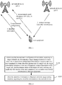
- FIG. 1 is a schematic diagram of an application scenario according to an embodiment of the present disclosure.
- the communication process between the user equipment and the network device includes the following procedures: (1) a user equipment completes normal cell measurement under a network device A and reports a measurement result through a measurement report, where the measurement report includes a frequency and a physical cell identifier (Physical Cell Identifier, PCI) of a cell B under a network device B; (2) the network device A determines that the cell B is an un-configured neighboring cell according to the frequency and the PCI in the measurement report, and the network device A instructs, through instruction signaling, the user equipment to obtain identifier information of the cell B, where the instruction signaling is transmitted to the user equipment form of measurement configuration; (3) after receiving the user equipment receives the measurement configuration, the user equipment starts a timer and starts to obtain a system message of the cell B, and further obtains the identifier information in the system message; (4) if the user equipment obtains the identifier information of the cell B before
- PCI Physical
- a timing duration of the timer is set based on the radio access technology (Radio Access Technology, RAT), and different RATs are corresponding to different timing durations.
- RAT Radio Access Technology
- the frequency of the NR system is divided into multiple frequency ranges. Different frequency ranges vary greatly in frequency bandwidth, subcarrier spacing, etc., and capabilities of the user equipment also vary greatly. If the method of setting the timing duration of the timer based on the RAT in the related art is adopted, the timing duration of the timer may be set unreasonably, which will affect obtaining of cell information and affecting effectiveness of communication.
- one embodiment of the present disclosure provides a method for obtaining cell information.
- the technical solutions provided in the embodiments of the present disclosure are described in detail hereinafter with reference to the accompanying drawings.
- FIG. 2 shows a method for obtaining cell information according to an embodiment of the present disclosure. As shown in FIG. 2 , the method includes the following steps.
- S210 when receiving measurement configuration information, according to target information, determining a target timing duration of a timer; where the measurement configuration information is used to instruct a user equipment to obtain identifier information of a target cell, the target information includes at least one of frequency related information of the target cell, synchronization status of the target cell and a serving cell, capability information of the user equipment, and operation state related information of the user equipment.
- the timer in the step S210 may be defined as stopping obtaining identifier information of the target cell (for example, a neighbor cell) and returning to the serving cell when the timer expires.
- a start time of the timer may be defined as a time when the measurement configuration information is received, or may be defined as a time when the user equipment reaches the target cell (for example, a neighbor cell) and starts to obtain the identifier information of the target cell.
- the measurement configuration information includes a frequency of the target cell and/or a physical cell identifier (Physical Cell Identifier, PCI).
- PCI Physical Cell Identifier
- the user equipment can determine the target cell according to information included in the measurement configuration information. Further, the measurement configuration information is associated with a measurement identifier (ID).
- the identifier information of the target cell may be information used to uniquely identify the target cell.
- the identifier information of the target cell includes at least one of a cell global identifier (Cell Global Identifier, CGI) of the target cell, a tracking area code (Tracking Area Code, TAC) of the target cell, and a public land mobile network (Public Land Mobile Network, PLMN) identifier of the target cell.
- CGI Cell Global Identifier
- TAC Tracking Area Code
- PLMN Public Land Mobile Network
- the target information includes frequency related information of the target cell.
- determining a target timing duration of a timer includes: determining the target timing duration according to a target frequency range to which the frequency of the target cell belongs.
- the user equipment determines the target timing duration according to the target frequency range and a first correspondence, where the first correspondence includes correspondence between frequency ranges and timing durations.
- the first correspondence may be pre-agreed by agreements, or may be configured by the network device for the user equipment through configuration information.
- the first correspondence may be as shown in Table 1.
- the target timing duration of the timer is M ms.
- the target timing duration of the timer is N ms.
- Table 1 Frequency range Timing duration A-B MHz Mms C-D MHz Nms
- the target information includes frequency related information of the target cell.
- determining a target timing duration of a timer includes: determining the target timing duration according to a target frequency bandwidth range to which a frequency bandwidth corresponding to the frequency of the target cell belongs.
- the user equipment determines the target timing duration according to the target frequency bandwidth range and a second correspondence, where the second correspondence includes correspondence between frequency bandwidth ranges and timing durations.
- the second correspondence may be pre-agreed by agreements, or may be configured by the network device for the user equipment through configuration information.
- the second correspondence may be as shown in Table 2.
- the target timing duration of the timer is M ms.
- the target timing duration of the timer is N ms.
- Table 2 Frequency bandwidth range Timing duration A MHz M ms B MHz N ms
- the target information includes frequency related information of the target cell.
- determining a target timing duration of a timer includes: determining the target timing duration of the timer according to a target subcarrier spacing corresponding to the frequency of the target cell.
- the user equipment determines the target timing duration according to the target subcarrier spacing and a third correspondence, where the third correspondence includes correspondence between subcarrier spacings and timing durations.
- the third correspondence may be pre-agreed by agreement, or may be configured by the network device for the user equipment through configuration information.
- the third correspondence may be as shown in Table 3.
- the target timing duration of the timer is 100 ms.
- the target timing duration of the timer is 200 ms.
- Table 3 Subcarrier spacing Timing duration 15 MHz 100 ms 30 MHz 200 ms
- the target information includes a synchronization status of the target cell and the serving cell.
- determining a target timing duration of a timer includes: when the target cell is synchronized with the serving cell, determining that the target timing duration of the timer is a first preset duration; and when the target cell is not synchronized with the serving cell, determining that the target timing duration of the timer is a second preset duration.
- the first preset duration and the second preset duration may be pre-agreed by agreements, or may be configured by the network device for the user equipment through configuration information.
- the user equipment determines whether the target cell is synchronized with the serving cell.
- the method shown in FIG. 2 further includes: receiving a system message of a serving cell, where the system message includes indication information indicating a synchronization status of the target cell and the serving cell; and determining synchronization status of the target cell and the serving cell according to the indication information.
- the capability information of the user equipment includes at least one of the following: a capability category (Category) of the user equipment, a measurement gap capability of the user equipment, connectivity mode supported by the user equipment, and a capability of the user equipment to support carrier aggregation or dual connectivity.
- the user equipment may determine the target timing duration of the timer based on at least one of the foregoing information included in the capability information.
- the user equipment determines the target timing duration according to a rule that the higher the capability category is, the shorter the target timing duration of the timer.
- a correspondence between the capability category and the timing duration may be configured by agreements or the network device, and the user equipment can determine the target timing duration according to its own capability category and the correspondence.
- the user equipment determines the target timing duration of the timer according to whether a measurement gap (Gap) is required for an indicated measurement frequency (frequency of the target cell). For example, when the measurement gap is not required for the indicated measurement frequency, then it is determined that the target timing duration is a short value.
- this short value may be pre-agreed by agreements or configured by the network device.
- the user equipment determines the target timing duration of the timer according to a supported connectivity mode. For example, when the user equipment only supports a LTE-NR dual-connectivity (Dual-Connectivity) mode and does not support a NR standalone (Standalone) mode, the target timing duration of the timer is a long value. When the user equipment device supports NR standalone mode, the target timing duration is a short value.
- the long value and the short value may be pre-agreed by agreements or configured by the network device.
- the user equipment determines the target timing duration of the timer according to the capability of supporting carrier aggregation or dual connectivity. For example, when the user equipment supports carrier aggregation for frequency bands or dual connectivity, the target timing duration of the timer is a short value.
- the short value may be pre-agreed by agreements or configured by the network device.
- the operation status related information of the user equipment includes at least one of the following: a connectivity mode in which the user equipment operates, a frequency band of carrier aggregation in which the user equipment operates, and a frequency band of a dual connectivity carrier in which the user equipment operates.
- the user equipment may determine the target timing duration of the timer based on at least one of the foregoing information included in the operation status related information.
- the user equipment determines the target timing duration of the timer according to the connectivity mode in which the user equipment operates.
- the radio access technology (Radio Access Technology, RAT) of the user equipment includes RAT corresponding to the target cell
- the target timing duration of the timer is a small value.
- the user equipment operates in the LTE-NR dual-connectivity mode, and the user equipment has both LTE connectivity and NR connectivity simultaneously; when the user equipment needs to obtain identifier information of an NR neighbor cell (or understood as that the user equipment needs to measure the NR neighbor cell), the target timing duration is set to be a smaller value.
- the target timing duration of the timer is set to be a larger value.
- the smaller value and the larger value may be pre-agreed by agreements or configured by the network device.
- the user equipment determines the target timing duration of the timer according to a frequency band of carrier aggregation in which the user equipment operates or a frequency band of a dual connectivity carrier in which the user equipment operates. For example, when there is a measured frequency band (band or frequency range) in the frequency band of the carrier aggregation in which the user equipment operates or the frequency band of the dual connectivity carrier in which the user equipment operates, the target timing duration of the timer is a small value.
- the small value may be pre-agreed by agreements or configured by the network device.
- the measurement configuration information is associated with a measurement identifier (ID).
- ID measurement identifier
- the user equipment reports the obtained identifier information and the measurement ID to the network device. Then the network device may add the target cell to the neighbor relation table of the serving cell.
- the user equipment reports the measurement ID to the network device. Since information reported by the user equipment does not include the identifier information, the network device can infer that the user equipment fails to obtain the required information, and then does not add the target cell to the neighbor relation table of the serving cell.
- the method for obtaining cell information according to one embodiment of the present disclosure is described in details above with reference to FIG. 2 .
- a user equipment according to an embodiment of the present disclosure will be described in detail hereinafter with reference to FIG. 3 .
- FIG. 3 is a schematic structural diagram of a user equipment according to an embodiment of the present disclosure.
- a user equipment 30 includes:
- the user equipment when receiving the measurement configuration information instructing the user equipment to obtain the identifier information of the target cell, according to the frequency related information of the target cell, the synchronization status of the target cell and the serving cell, the capability information of the user equipment, and operation status related information of the user equipment, the user equipment determines the target timing duration of the timer.
- the identifier information of the target cell is obtained within the target timing duration, the user equipment reports the identifier information to the network device. In this way, a more reasonable timing duration may be determined in the new radio (NR) system, and the cell information may be obtained based on the determined timing duration, thereby improving communication effectiveness.
- NR new radio
- the target information includes frequency related information of the target cell.
- the determining module 31 is specifically configured to: determine the target timing duration according to a target frequency range to which the frequency of the target cell belongs.
- the determining module 31 is specifically configured to:
- the target information includes frequency related information of the target cell.
- the determining module 31 is specifically configured to: determine the target timing duration according to a target frequency bandwidth range to which a frequency bandwidth corresponding to the frequency of the target cell belongs.
- the determining module 31 is specifically configured to:
- the target information includes frequency related information of the target cell.
- the determining module 31 is specifically configured to: determine the target timing duration of the timer according to a target subcarrier spacing corresponding to the frequency of the target cell.
- the determining module 31 is specifically configured to:
- the target information includes a synchronization status between the target cell and a serving cell.
- the determining module 31 is specifically configured to:
- the transceiver module 32 is further configured to:
- the capability information of the user equipment includes at least one of the following: a capability category of the user equipment, a measurement gap capability of the user equipment, connectivity mode supported by the user equipment, and a capability of the user equipment to support carrier aggregation or dual connectivity.
- the operation status related information of the user equipment includes at least one of the following: a connectivity mode in which the user equipment operates, a frequency band of carrier aggregation in which the user equipment operates, and a frequency band of a dual connectivity carrier in which the user equipment operates.
- the measurement configuration information includes a frequency of the target cell and/or a physical cell identifier (PCI).
- PCI physical cell identifier
- the identifier information of the target cell includes at least one of a cell global identifier (CGI) of the target cell, a tracking area code (TAC) of the target cell, and a public land mobile network (PLMN) identifier of the target cell.
- CGI cell global identifier
- TAC tracking area code
- PLMN public land mobile network
- the user equipment provided in the embodiment of the present disclosure can implement various procedures implemented by the user equipment in the method embodiment of FIG. 1 . To avoid repetition, details are not described herein again.
- FIG. 4 is a schematic structural diagram of a user equipment according to another embodiment of the present disclosure.
- the user equipment 400 includes at least one processor 410, a memory 420, at least one network interface 430, and a user interface 440.
- Various components in the user equipment 400 are coupled together by a bus system 450.
- the bus system 450 is configured to implement connection communication among these components.
- the bus system 450 further includes power bus, control bus and status signal bus.
- various buses are labeled as bus system 450 in FIG. 4 .
- the user interface 440 may include a display device, a keyboard, or a clicking device (e.g., a mouse, a trackball, a touchpad, or a touch screen, etc.).
- a clicking device e.g., a mouse, a trackball, a touchpad, or a touch screen, etc.
- the memory 420 may be a transitory memory, or a non-transitory memory, or may include both of the transitory memory and the non-transitory memory.
- the non-transitory memory may be a read-only memory (Read-Only Memory, ROM), a programmable ROM (Programmable ROM, PROM), an erasable PROM (Erasable PROM, EPROM), an electrically EPROM (Electrically EPROM, EEPROM), or a flash memory.
- the transitory memory may be a random access memory (Random Access Memory, RAM), which is used as an external cache.
- RAM random access memory
- SRAM static RAM
- DRAM dynamic RAM
- DRAM synchronous DRAM
- SDRAM double data rate SDRAM
- DDRSDRAM Double Data Rate SDRAM
- ESDRAM enhanced SDRAM
- synchlink DRAM synchlink DRAM
- SLDRAM direct rambus RAM
- DRRAM direct Rambus RAM
- the memory 420 stores the following elements, executable modules, or data structures, or a subset thereof, or an extended set thereof: an operating system (OS) 421 and an application program 422.
- OS operating system
- the operating system 421 includes various system programs, e.g., a frame layer, a core library layer, a driver layer, etc., are used to implement various basic services and to handle hardware-based tasks.
- the application program 422 includes various applications, such as a media player (Media Player), a browser, and so on, for implementing various application services.
- a program implementing the method of the embodiments in the present disclosure may be included in the application program 422.
- the user equipment 400 further includes: a computer program stored on the memory 420 and executable on the processor 410.
- the computer program is executed by the processor 410 to implement various steps of the method shown in FIG. 2 and the same technical effect can be achieved. In order to avoid repetition, it will not be repeated here.
- the method provided by foregoing embodiments of the present disclosure may be applied to the processor 410, or may be implemented by the processor 410.
- the processor 410 may be an integrated circuit chip with signal processing capability. During the implementation process, each step of the foregoing method may be completed by an integrated logic circuit of hardware in the processor 410, or by an instruction in a form of software.
- the foregoing processor 410 may be a general processor, a digital signal processor (Digital Signal Processor, DSP), an application specific integrated circuit (Application Specific Integrated Circuit, ASIC), a field programmable gate array (Field Programmable Gate Array, FPGA), or other programmable logic devices, discrete gate or transistor logic device, discrete hardware components.
- DSP Digital Signal Processor
- ASIC Application Specific Integrated Circuit
- FPGA Field Programmable Gate Array
- the general processor may be a microprocessor, or any conventional processor, and so on.
- the steps of the method provided by the embodiments of the present disclosure may be directly completed by the hardware decoding processor, or may be completed by a combination of hardware and software modules in the decoding processor.
- the software modules may be located in mature storage medium in the field, such as, the RAM, the flash memory, the ROM, the PROM, Electrically erasable programmable memory, and a register.
- the storage medium is located in the memory 420.
- the processor 410 reads information from the memory 420, and completes steps of foregoing method in combination with the hardware.
- a computer program is stored on the computer readable storage medium, and the computer program is executed by the processor 410 to implement various steps of the method shown in FIG. 2 .
- a processing unit may be implemented in one or more application specific integrated circuit (Application Specific Integrated Circuits, ASICs), digital signal processor (Digital Signal Processor, DSP), DSP device (DSP Device, DSPD), programmable logic device (Programmable Logic Device, PLD), field-programmable gate array (Field-Programmable Gate Array, FPGA), general processors, controllers, microcontrollers, microprocessors, another electronic unit configured to implement the functions of the application or a combination thereof.
- ASICs Application Specific Integrated Circuits
- DSP Digital Signal Processor
- DSP Device DSP Device
- DSPD programmable logic device
- PLD programmable logic device
- FPGA field-programmable gate array
- general processors controllers, microcontrollers, microprocessors, another electronic unit configured to implement the functions of the application or a combination thereof.
- modules e.g., process, function, etc.
- Software codes may be stored in the memory, and executed by the processor.
- the memory may be implemented in the processor, or external to the processor.
- the present disclosure further provides a computer readable storage medium.
- the computer readable storage medium stores a computer program thereon.
- the computer program is executed by a processor to implement various steps of the method shown in FIG. 2 and the same technical effect can be achieved. In order to avoid repetition, it will not be repeated here.
- the computer readable storage medium may be a read-only memory (Read-Only Memory, ROM), a random access memory (Random Access Memory, RAM), a magnetic disk, and an optical disk.
- a computer software product is stored in a storage medium (such as ROM/RAM, magnetic disk, optical disk), including several instructions to enable a terminal (which may be a mobile phone, a computer, a server, an air conditioner, or a network device, etc.) to execute the method described in each embodiment of the present disclosure.
- a storage medium such as ROM/RAM, magnetic disk, optical disk
Landscapes
- Engineering & Computer Science (AREA)
- Computer Networks & Wireless Communication (AREA)
- Signal Processing (AREA)
- Mobile Radio Communication Systems (AREA)
Abstract
Description
- This application claims the benefit and priority of Chinese Application No.
201810260183.9, filed on March 27, 2018 - The present application relates to the field of communications technology, and in particular to a method and device for obtaining cell information.
- In communication systems, in order to perform handover and interference coordination, a network device (for example, eNB) needs to establish and maintain a neighbor relation table for cells under the network device. Automatic neighbor relation (Automatic Neighbor Relation, ANR) function is used to assist the network device in discovering un-configured neighboring cells and trigger establishment and maintenance of corresponding entries in the neighbor relation table. The automatic neighbor relation mechanism is not only suitable for discovering intra-frequency neighbor cells, but also for discovering inter-frequency neighbor cells.
- In the related art, in the automatic neighbor relation mechanism, after a user equipment receives ANR measurement configuration issued by the network device, the user equipment starts a timer T321. A timing duration of the timer T321 is set based on the radio access technology (Radio Access Technology, RAT), and different RATs are corresponding to different timing durations.
- However, for the new radio (New Radio, NR) system, the frequency of the NR system is divided into multiple frequency ranges. Different frequency ranges vary greatly in frequency bandwidth, subcarrier spacing, etc., and capabilities of user equipment also vary greatly. If the method of setting the timing duration of the timer based on the RAT in the related art is adopted, the timing duration of the timer may be set unreasonably, which will affect obtaining of cell information and affecting effectiveness of communication.
- An object of embodiments of the present disclosure is to provide a method and device for obtaining cell information, which can provide a solution for the user equipment in the NR system to determine the timing duration of the timer, thereby enabling the user equipment to obtain cell information according to a more reasonable timing duration and then improving communication effectiveness.
- In a first aspect, a method for obtaining cell information is provided and includes:
- when receiving measurement configuration information, according to target information, determining a target timing duration of a timer; wherein the measurement configuration information is configured to instruct the user equipment to obtain identifier information of a target cell, the target information includes at least one of: frequency related information of the target cell, synchronization status of the target cell and a serving cell, capability information of the user equipment, and operation state related information of the user equipment;
- when the identifier information is obtained within the target timing duration, reporting the identifier information to a network device.
- In a second aspect, a user equipment is provided and includes:
- a determining module configured to, when receiving measurement configuration information, according to target information, determine a target timing duration of a timer; wherein the measurement configuration information is configured to instruct the user equipment to obtain identifier information of a target cell, the target information includes at least one of frequency related information of the target cell, synchronization status of the target cell and a serving cell, capability information of the user equipment, and operation state related information of the user equipment;
- a transceiver module configured to, when the identifier information is obtained within the target timing duration, report the identifier information to a network device.
- In a third aspect, a user equipment is provided and includes: a memory, a processor, and a computer program stored on the memory and executable on the processor; wherein the computer program is executed by the processor to implement steps of the method for obtaining cell information in the first aspect.
- In a fourth aspect, a computer readable medium is provided and includes a computer program stored thereon; wherein the computer program is executed by a processor to implement steps of the method for obtaining cell information in the first aspect.
- In the embodiment of the present disclosure, when receiving the measurement configuration information instructing the user equipment to obtain the identifier information of the target cell, according to the frequency related information of the target cell, the synchronization status of the target cell and the serving cell, the capability information of the user equipment, and operation status related information of the user equipment, the user equipment determines the target timing duration of the timer. When the identifier information of the target cell is obtained within the target timing duration, the user equipment reports the identifier information to the network device. In this way, a more reasonable timing duration may be determined in the new radio (NR) system, and the cell information may be obtained based on the determined timing duration, thereby improving communication effectiveness.
- The drawings described herein are used to provide a further understanding of the present disclosure and constitute a part of the present disclosure. The exemplary embodiments and descriptions of the present disclosure are used to explain the present disclosure, and do not constitute an improper limitation of the present disclosure. In the drawings:
-
FIG. 1 is a schematic diagram of an application scenario of an embodiment of the present disclosure; -
FIG. 2 is a schematic flow chart of a method for obtaining cell information according to an embodiment of the present disclosure; -
FIG. 3 is a schematic structural diagram of a user equipment according to an embodiment of the present disclosure; and -
FIG. 4 is a schematic structural diagram of a user equipment according to an embodiment of the present disclosure. - The technical solutions in embodiments of the present disclosure will be described hereinafter in a clear and complete manner in conjunction with the drawings in the embodiments of the present disclosure. Obviously, the following embodiments are merely a part of, rather than all of, the embodiments of the present disclosure, and based on these embodiments, a person skilled in the art may obtain the other embodiments, which also fall within the scope of the present disclosure.
- The technical solution of the present disclosure may be applied to various communication systems, such as long term evolution (Long Term Evolution, LTE)/long term evolution-advanced (Long Term Evolution-advanced, LTE-A) system, New Radio (NR) system.
- A user equipment (User Equipment, UE), which may also be referred as a mobile terminal (Mobile Terminal) or a mobile user equipment, etc., may communicate with one or more core networks via a radio access network (for example, Radio Access Network, RAN). The user equipment may be a mobile terminal, such as a mobile phone (or referred as "cellular" phone), or a computer with a mobile terminal, such as, a portable, pocket-sized, hand-held, built-in computer or vehicle-mounted mobile device, which exchanges languages and/or data with the radio access network.
- The network device is a device that is deployed in the radio access network to provide a wireless communication function for the user equipment. The network device may be a base station, and may be an evolved base station (eNB or e-NodeB, evolutional Node B) in the LTE or a 5G base station (gNB).
-
FIG. 1 is a schematic diagram of an application scenario according to an embodiment of the present disclosure. As shown inFIG. 1 , the communication process between the user equipment and the network device includes the following procedures: (1) a user equipment completes normal cell measurement under a network device A and reports a measurement result through a measurement report, where the measurement report includes a frequency and a physical cell identifier (Physical Cell Identifier, PCI) of a cell B under a network device B; (2) the network device A determines that the cell B is an un-configured neighboring cell according to the frequency and the PCI in the measurement report, and the network device A instructs, through instruction signaling, the user equipment to obtain identifier information of the cell B, where the instruction signaling is transmitted to the user equipment form of measurement configuration; (3) after receiving the user equipment receives the measurement configuration, the user equipment starts a timer and starts to obtain a system message of the cell B, and further obtains the identifier information in the system message; (4) if the user equipment obtains the identifier information of the cell B before the timer expires, the user equipment reports the identifier information to the network device A, and the network device A adds the cell B to a neighbor relation table of a serving cell (cell A) of the user equipment. - In the related art, a timing duration of the timer is set based on the radio access technology (Radio Access Technology, RAT), and different RATs are corresponding to different timing durations. For the new radio (New Radio, NR) system, the frequency of the NR system is divided into multiple frequency ranges. Different frequency ranges vary greatly in frequency bandwidth, subcarrier spacing, etc., and capabilities of the user equipment also vary greatly. If the method of setting the timing duration of the timer based on the RAT in the related art is adopted, the timing duration of the timer may be set unreasonably, which will affect obtaining of cell information and affecting effectiveness of communication.
- In order to solve the above problem, one embodiment of the present disclosure provides a method for obtaining cell information. The technical solutions provided in the embodiments of the present disclosure are described in detail hereinafter with reference to the accompanying drawings.
-
FIG. 2 shows a method for obtaining cell information according to an embodiment of the present disclosure. As shown inFIG. 2 , the method includes the following steps. - S210: when receiving measurement configuration information, according to target information, determining a target timing duration of a timer; where the measurement configuration information is used to instruct a user equipment to obtain identifier information of a target cell, the target information includes at least one of frequency related information of the target cell, synchronization status of the target cell and a serving cell, capability information of the user equipment, and operation state related information of the user equipment.
- It should be noted that the timer in the step S210 may be defined as stopping obtaining identifier information of the target cell (for example, a neighbor cell) and returning to the serving cell when the timer expires. A start time of the timer may be defined as a time when the measurement configuration information is received, or may be defined as a time when the user equipment reaches the target cell (for example, a neighbor cell) and starts to obtain the identifier information of the target cell.
- Optionally, in the step S210, the measurement configuration information includes a frequency of the target cell and/or a physical cell identifier (Physical Cell Identifier, PCI). The user equipment can determine the target cell according to information included in the measurement configuration information. Further, the measurement configuration information is associated with a measurement identifier (ID).
- Optionally, in the step S210, the identifier information of the target cell may be information used to uniquely identify the target cell. For example, the identifier information of the target cell includes at least one of a cell global identifier (Cell Global Identifier, CGI) of the target cell, a tracking area code (Tracking Area Code, TAC) of the target cell, and a public land mobile network (Public Land Mobile Network, PLMN) identifier of the target cell.
- Optionally, in some embodiments, the target information includes frequency related information of the target cell. Then, in the step S210, according to target information, determining a target timing duration of a timer, includes: determining the target timing duration according to a target frequency range to which the frequency of the target cell belongs.
- Further, the user equipment determines the target timing duration according to the target frequency range and a first correspondence, where the first correspondence includes correspondence between frequency ranges and timing durations. Here, the first correspondence may be pre-agreed by agreements, or may be configured by the network device for the user equipment through configuration information.
- For example, the first correspondence may be as shown in Table 1. When the user equipment determines that the frequency of the target cell belongs to a frequency range A-B MHz, then it is determined that the target timing duration of the timer is M ms. When the user equipment determines the frequency of the target cell belongs to a frequency range C-D MHz, then it is determined that the target timing duration of the timer is N ms.
Table 1 Frequency range Timing duration A-B MHz Mms C-D MHz Nms - Optionally, in other embodiments, the target information includes frequency related information of the target cell. Then, in the step S210, according to target information, determining a target timing duration of a timer, includes: determining the target timing duration according to a target frequency bandwidth range to which a frequency bandwidth corresponding to the frequency of the target cell belongs.
- Further, the user equipment determines the target timing duration according to the target frequency bandwidth range and a second correspondence, where the second correspondence includes correspondence between frequency bandwidth ranges and timing durations. Here, the second correspondence may be pre-agreed by agreements, or may be configured by the network device for the user equipment through configuration information.
- For example, the second correspondence may be as shown in Table 2. When the user equipment determines that the frequency bandwidth range corresponding to the frequency of the target cell belongs to a frequency bandwidth range A MHz, then it is determined that the target timing duration of the timer is M ms. When the user equipment determines that the frequency bandwidth range corresponding to the frequency of the target cell belongs to the frequency bandwidth range B MHz, then it is determined that the target timing duration of the timer is N ms.
Table 2 Frequency bandwidth range Timing duration A MHz M ms B MHz N ms - Optionally, in other embodiments, the target information includes frequency related information of the target cell. Then, in the step S210, according to target information, determining a target timing duration of a timer, includes: determining the target timing duration of the timer according to a target subcarrier spacing corresponding to the frequency of the target cell.
- Further, the user equipment determines the target timing duration according to the target subcarrier spacing and a third correspondence, where the third correspondence includes correspondence between subcarrier spacings and timing durations. Here, the third correspondence may be pre-agreed by agreement, or may be configured by the network device for the user equipment through configuration information.
- For example, the third correspondence may be as shown in Table 3. When the user equipment determines that the target subcarrier spacing corresponding to the frequency of the target cell is 15 MHz, then it is determined that the target timing duration of the timer is 100 ms. When the user equipment determines that the target subcarrier spacing corresponding to the frequency of the target cell is 30 MHz, then it is determined that the target timing duration of the timer is 200 ms.
Table 3 Subcarrier spacing Timing duration 15 MHz 100 ms 30 MHz 200 ms - Optionally, in other embodiments, the target information includes a synchronization status of the target cell and the serving cell. Then, in the step S210, according to target information, determining a target timing duration of a timer, includes: when the target cell is synchronized with the serving cell, determining that the target timing duration of the timer is a first preset duration; and when the target cell is not synchronized with the serving cell, determining that the target timing duration of the timer is a second preset duration. Here, the first preset duration and the second preset duration may be pre-agreed by agreements, or may be configured by the network device for the user equipment through configuration information.
- Further, according to the system message of the serving cell, the user equipment determines whether the target cell is synchronized with the serving cell. The method shown in
FIG. 2 further includes: receiving a system message of a serving cell, where the system message includes indication information indicating a synchronization status of the target cell and the serving cell; and determining synchronization status of the target cell and the serving cell according to the indication information. - In one embodiment of the present disclosure, optionally, the capability information of the user equipment includes at least one of the following: a capability category (Category) of the user equipment, a measurement gap capability of the user equipment, connectivity mode supported by the user equipment, and a capability of the user equipment to support carrier aggregation or dual connectivity. Correspondingly, the user equipment may determine the target timing duration of the timer based on at least one of the foregoing information included in the capability information.
- For example, the user equipment determines the target timing duration according to a rule that the higher the capability category is, the shorter the target timing duration of the timer. Alternatively, a correspondence between the capability category and the timing duration may be configured by agreements or the network device, and the user equipment can determine the target timing duration according to its own capability category and the correspondence.
- Alternatively, the user equipment determines the target timing duration of the timer according to whether a measurement gap (Gap) is required for an indicated measurement frequency (frequency of the target cell). For example, when the measurement gap is not required for the indicated measurement frequency, then it is determined that the target timing duration is a short value. Here, this short value may be pre-agreed by agreements or configured by the network device.
- Alternatively, the user equipment determines the target timing duration of the timer according to a supported connectivity mode. For example, when the user equipment only supports a LTE-NR dual-connectivity (Dual-Connectivity) mode and does not support a NR standalone (Standalone) mode, the target timing duration of the timer is a long value. When the user equipment device supports NR standalone mode, the target timing duration is a short value. Here, the long value and the short value may be pre-agreed by agreements or configured by the network device.
- Alternatively, the user equipment determines the target timing duration of the timer according to the capability of supporting carrier aggregation or dual connectivity. For example, when the user equipment supports carrier aggregation for frequency bands or dual connectivity, the target timing duration of the timer is a short value. Here, the short value may be pre-agreed by agreements or configured by the network device.
- In one embodiment of the present disclosure, optionally, the operation status related information of the user equipment includes at least one of the following: a connectivity mode in which the user equipment operates, a frequency band of carrier aggregation in which the user equipment operates, and a frequency band of a dual connectivity carrier in which the user equipment operates. Correspondingly, the user equipment may determine the target timing duration of the timer based on at least one of the foregoing information included in the operation status related information.
- For example, the user equipment determines the target timing duration of the timer according to the connectivity mode in which the user equipment operates. When the radio access technology (Radio Access Technology, RAT) of the user equipment includes RAT corresponding to the target cell, the target timing duration of the timer is a small value. For example, the user equipment operates in the LTE-NR dual-connectivity mode, and the user equipment has both LTE connectivity and NR connectivity simultaneously; when the user equipment needs to obtain identifier information of an NR neighbor cell (or understood as that the user equipment needs to measure the NR neighbor cell), the target timing duration is set to be a smaller value. When the user equipment operates in the LTE single connectivity without NR connectivity, the target timing duration of the timer is set to be a larger value. Here, the smaller value and the larger value may be pre-agreed by agreements or configured by the network device.
- Alternatively, the user equipment determines the target timing duration of the timer according to a frequency band of carrier aggregation in which the user equipment operates or a frequency band of a dual connectivity carrier in which the user equipment operates. For example, when there is a measured frequency band (band or frequency range) in the frequency band of the carrier aggregation in which the user equipment operates or the frequency band of the dual connectivity carrier in which the user equipment operates, the target timing duration of the timer is a small value. Here, the small value may be pre-agreed by agreements or configured by the network device.
- S220: when the identifier information is obtained within the target timing duration, reporting the identifier information to the network device.
- Specifically, in some embodiments, the measurement configuration information is associated with a measurement identifier (ID). When the user equipment obtains the identifier information within the target timing duration, the user equipment reports the obtained identifier information and the measurement ID to the network device. Then the network device may add the target cell to the neighbor relation table of the serving cell. When the user equipment does not obtain the identifier information within the target timing duration, the user equipment reports the measurement ID to the network device. Since information reported by the user equipment does not include the identifier information, the network device can infer that the user equipment fails to obtain the required information, and then does not add the target cell to the neighbor relation table of the serving cell.
- The method for obtaining cell information according to one embodiment of the present disclosure is described in details above with reference to
FIG. 2 . A user equipment according to an embodiment of the present disclosure will be described in detail hereinafter with reference toFIG. 3 . -
FIG. 3 is a schematic structural diagram of a user equipment according to an embodiment of the present disclosure. As shown inFIG. 3 , a user equipment 30 includes: - a determining
module 31 configured to, when receiving measurement configuration information, according to target information, determine a target timing duration of a timer; where the measurement configuration information is used to instruct a user equipment to obtain identifier information of a target cell, the target information includes at least one of frequency related information of the target cell, synchronization status of the target cell and a serving cell, capability information of the user equipment, and operation state related information of the user equipment; - a
transceiver module 32 configured to, when the identifier information is obtained within the target timing duration, report the identifier information to the network device. - According to the user equipment in the embodiment of the present disclosure, when receiving the measurement configuration information instructing the user equipment to obtain the identifier information of the target cell, according to the frequency related information of the target cell, the synchronization status of the target cell and the serving cell, the capability information of the user equipment, and operation status related information of the user equipment, the user equipment determines the target timing duration of the timer. When the identifier information of the target cell is obtained within the target timing duration, the user equipment reports the identifier information to the network device. In this way, a more reasonable timing duration may be determined in the new radio (NR) system, and the cell information may be obtained based on the determined timing duration, thereby improving communication effectiveness.
- Optionally, as an example, the target information includes frequency related information of the target cell.
- The determining
module 31 is specifically configured to:
determine the target timing duration according to a target frequency range to which the frequency of the target cell belongs. - Optionally, as an example, the determining
module 31 is specifically configured to: - determine the target timing duration according to the target frequency range and a first correspondence,
- where the first correspondence includes correspondence between frequency ranges and timing durations.
- Optionally, as an example, the target information includes frequency related information of the target cell.
- The determining
module 31 is specifically configured to:
determine the target timing duration according to a target frequency bandwidth range to which a frequency bandwidth corresponding to the frequency of the target cell belongs. - Optionally, as an example, the determining
module 31 is specifically configured to: - determine the target timing duration according to the target frequency bandwidth range and a second correspondence;
- where the second correspondence includes correspondence between frequency bandwidth ranges and timing durations.
- Optionally, as an example, the target information includes frequency related information of the target cell.
- The determining
module 31 is specifically configured to:
determine the target timing duration of the timer according to a target subcarrier spacing corresponding to the frequency of the target cell. - Optionally, as an example, the determining
module 31 is specifically configured to: - determine the target timing duration according to the target subcarrier spacing and a third correspondence;
- where the third correspondence includes correspondence between subcarrier spacings and timing durations.
- Optionally, as an example, the target information includes a synchronization status between the target cell and a serving cell.
- The determining
module 31 is specifically configured to: - when the target cell is synchronized with the serving cell, determine that the target timing duration is a first preset duration; and
- when the target cell is not synchronized with the serving cell, determine that the target timing duration is a second preset duration.
- Optionally, as an example, the
transceiver module 32 is further configured to: - receive a system message of a serving cell, where the system message includes indication information indicating a synchronization status of the target cell and the serving cell; and
- determine synchronization status of the target cell and the serving cell according to the indication information.
- Optionally, as an example, the capability information of the user equipment includes at least one of the following: a capability category of the user equipment, a measurement gap capability of the user equipment, connectivity mode supported by the user equipment, and a capability of the user equipment to support carrier aggregation or dual connectivity.
- Optionally, as an example, the operation status related information of the user equipment includes at least one of the following: a connectivity mode in which the user equipment operates, a frequency band of carrier aggregation in which the user equipment operates, and a frequency band of a dual connectivity carrier in which the user equipment operates.
- Optionally, as an example, the measurement configuration information includes a frequency of the target cell and/or a physical cell identifier (PCI).
- Optionally, as an example, the identifier information of the target cell includes at least one of a cell global identifier (CGI) of the target cell, a tracking area code (TAC) of the target cell, and a public land mobile network (PLMN) identifier of the target cell.
- The user equipment provided in the embodiment of the present disclosure can implement various procedures implemented by the user equipment in the method embodiment of
FIG. 1 . To avoid repetition, details are not described herein again. -
FIG. 4 is a schematic structural diagram of a user equipment according to another embodiment of the present disclosure. As shown inFIG. 4 , theuser equipment 400 includes at least oneprocessor 410, amemory 420, at least onenetwork interface 430, and auser interface 440. Various components in theuser equipment 400 are coupled together by abus system 450. It should be understood that, thebus system 450 is configured to implement connection communication among these components. In addition to data bus, thebus system 450 further includes power bus, control bus and status signal bus. However, for clarity of description, various buses are labeled asbus system 450 inFIG. 4 . - The
user interface 440 may include a display device, a keyboard, or a clicking device (e.g., a mouse, a trackball, a touchpad, or a touch screen, etc.). - It should be understood that, in the embodiment of the present disclosure, the
memory 420 may be a transitory memory, or a non-transitory memory, or may include both of the transitory memory and the non-transitory memory. The non-transitory memory may be a read-only memory (Read-Only Memory, ROM), a programmable ROM (Programmable ROM, PROM), an erasable PROM (Erasable PROM, EPROM), an electrically EPROM (Electrically EPROM, EEPROM), or a flash memory. The transitory memory may be a random access memory (Random Access Memory, RAM), which is used as an external cache. Many forms of RAM are available by way of illustration and not limitation, e.g., a static RAM (Static RAM, SRAM), a dynamic RAM (Dynamic RAM, DRAM), a synchronous DRAM (Synchronous DRAM, SDRAM), a double data rate SDRAM (Double Data Rate SDRAM, DDRSDRAM), an enhanced SDRAM (Enhanced SDRAM, ESDRAM), a synchlink DRAM (Synchlink DRAM, SLDRAM) and a direct rambus RAM (Direct Rambus RAM, DRRAM). Thememory 420 of the systems and methods described in the application is intended to include, without being limited to, these and any other suitable types of memory. - In some implementations, the
memory 420 stores the following elements, executable modules, or data structures, or a subset thereof, or an extended set thereof: an operating system (OS) 421 and anapplication program 422. - The
operating system 421 includes various system programs, e.g., a frame layer, a core library layer, a driver layer, etc., are used to implement various basic services and to handle hardware-based tasks. Theapplication program 422 includes various applications, such as a media player (Media Player), a browser, and so on, for implementing various application services. A program implementing the method of the embodiments in the present disclosure may be included in theapplication program 422. - In one embodiment of the present disclosure, the
user equipment 400 further includes: a computer program stored on thememory 420 and executable on theprocessor 410. The computer program is executed by theprocessor 410 to implement various steps of the method shown inFIG. 2 and the same technical effect can be achieved. In order to avoid repetition, it will not be repeated here. - The method provided by foregoing embodiments of the present disclosure may be applied to the
processor 410, or may be implemented by theprocessor 410. Theprocessor 410 may be an integrated circuit chip with signal processing capability. During the implementation process, each step of the foregoing method may be completed by an integrated logic circuit of hardware in theprocessor 410, or by an instruction in a form of software. The foregoingprocessor 410 may be a general processor, a digital signal processor (Digital Signal Processor, DSP), an application specific integrated circuit (Application Specific Integrated Circuit, ASIC), a field programmable gate array (Field Programmable Gate Array, FPGA), or other programmable logic devices, discrete gate or transistor logic device, discrete hardware components. Each method, step, and logic diagram provided by the embodiment of the present disclosure may be implemented, or executed. The general processor may be a microprocessor, or any conventional processor, and so on. The steps of the method provided by the embodiments of the present disclosure may be directly completed by the hardware decoding processor, or may be completed by a combination of hardware and software modules in the decoding processor. The software modules may be located in mature storage medium in the field, such as, the RAM, the flash memory, the ROM, the PROM, Electrically erasable programmable memory, and a register. The storage medium is located in thememory 420. Theprocessor 410 reads information from thememory 420, and completes steps of foregoing method in combination with the hardware. Specifically, a computer program is stored on the computer readable storage medium, and the computer program is executed by theprocessor 410 to implement various steps of the method shown inFIG. 2 . - It should be understood that, these embodiments described in the application may be implemented by hardware, software, firmware, middleware, microcode, or a combination thereof. For hardware implementation, a processing unit may be implemented in one or more application specific integrated circuit (Application Specific Integrated Circuits, ASICs), digital signal processor (Digital Signal Processor, DSP), DSP device (DSP Device, DSPD), programmable logic device (Programmable Logic Device, PLD), field-programmable gate array (Field-Programmable Gate Array, FPGA), general processors, controllers, microcontrollers, microprocessors, another electronic unit configured to implement the functions of the application or a combination thereof.
- For software implementation, techniques described in the application may be implemented, by executing modules (e.g., process, function, etc.) with corresponding functions in the application. Software codes may be stored in the memory, and executed by the processor. The memory may be implemented in the processor, or external to the processor.
- One embodiment of the present disclosure further provides a computer readable storage medium. The computer readable storage medium stores a computer program thereon. The computer program is executed by a processor to implement various steps of the method shown in
FIG. 2 and the same technical effect can be achieved. In order to avoid repetition, it will not be repeated here. The computer readable storage medium, for example, may be a read-only memory (Read-Only Memory, ROM), a random access memory (Random Access Memory, RAM), a magnetic disk, and an optical disk. - It should also be noted that in this application, the term "including", "include" or any variants thereof is intended to cover a non-exclusive contain, so that a process, a method, an article or a device, which includes a series of elements, includes not only those elements, but also includes other elements which are not explicitly listed, or elements inherent in such a process, method, article or device. In absence of any further restrictions, an element defined by the phrase "including one..." does not exclude the existence of additional identical elements in a process, method, article, or device that includes the element.
- Through the description of the above embodiments, those skilled in the art can clearly understand that the foregoing embodiment method can be implemented by means of software plus a necessary general hardware platform, and of course, can also be through hardware, but in many cases, the former is better. Based on such understanding, the technical solution of the present disclosure essentially or the part that contributes to the prior art may be embodied in the form of a software product. A computer software product is stored in a storage medium (such as ROM/RAM, magnetic disk, optical disk), including several instructions to enable a terminal (which may be a mobile phone, a computer, a server, an air conditioner, or a network device, etc.) to execute the method described in each embodiment of the present disclosure.
- The embodiments of the present disclosure have been described above with reference to the drawings, but the present disclosure is not limited to the foregoing specific embodiments. The foregoing specific embodiments are merely illustrative and not restrictive. In the light of the present disclosure, those skilled in the art may make many variations without departing from the sprit and the protection scope of the claims, which fall within the protection of the present disclosure.
Claims (28)
- A method for obtaining cell information, to a user equipment, comprising:when receiving measurement configuration information, according to target information, determining a target timing duration of a timer; wherein the measurement configuration information is configured to instruct the user equipment to obtain identifier information of a target cell, the target information comprises at least one of: frequency related information of the target cell, synchronization status of the target cell and a serving cell, capability information of the user equipment, and operation state related information of the user equipment;when the identifier information is obtained within the target timing duration, reporting the identifier information to a network device.
- The method according to claim 1, wherein the target information comprises the frequency related information of the target cell;
wherein according to target information, determining a target timing duration of a timer, comprises:
determining the target timing duration according to a target frequency range to which the frequency of the target cell belongs. - The method according to claim 2, wherein determining the target timing duration according to a target frequency range to which the frequency of the target cell belongs, comprises:determining the target timing duration according to the target frequency range and a first correspondence;wherein the first correspondence comprises correspondence between frequency ranges and timing durations.
- The method according to claim 1, wherein the target information comprises the frequency related information of the target cell;
wherein according to target information, determining a target timing duration of a timer, comprises:
determining the target timing duration according to a target frequency bandwidth range to which a frequency bandwidth corresponding to the frequency of the target cell belongs. - The method according to claim 4, wherein determining the target timing duration according to a target frequency bandwidth range to which a frequency bandwidth corresponding to the frequency of the target cell belongs, comprises:determining the target timing duration according to the target frequency bandwidth range and a second correspondence;wherein the second correspondence comprises correspondence between frequency bandwidth ranges and timing durations.
- The method according to claim 1, wherein the target information comprises the frequency related information of the target cell;
wherein according to target information, determining a target timing duration of a timer, comprises:
determining the target timing duration of the timer according to a target subcarrier spacing corresponding to the frequency of the target cell. - The method according to claim 6, wherein determining the target timing duration of the timer according to a target subcarrier spacing corresponding to the frequency of the target cell, comprises:determining the target timing duration according to the target subcarrier spacing and a third correspondence;wherein the third correspondence comprises correspondence between subcarrier spacings and timing durations.
- The method according to claim 1, wherein the target information comprises the synchronization status of the target cell and the serving cell;
wherein according to target information, determining a target timing duration of a timer, comprises:when the target cell is synchronized with the serving cell, determining that the target timing duration is a first preset duration; andwhen the target cell is not synchronized with the serving cell, determining that the target timing duration is a second preset duration. - The method according to claim 8, further comprising:receiving a system message of the serving cell, wherein the system message comprises indication information indicating the synchronization status of the target cell and the serving cell; anddetermining synchronization status of the target cell and the serving cell according to the indication information.
- The method according to any one of claims 1 to 9, wherein the capability information of the user equipment comprises at least one of the following: a capability category of the user equipment, a measurement gap capability of the user equipment, connectivity mode supported by the user equipment, and a capability of the user equipment to support carrier aggregation or dual connectivity.
- The method according to any one of claims 1 to 9, wherein the operation status related information of the user equipment comprises at least one of the following: a connectivity mode in which the user equipment operates, a frequency band of carrier aggregation in which the user equipment operates, and a frequency band of a dual connectivity carrier in which the user equipment operates.
- The method according to any one of claims 1 to 9, wherein the measurement configuration information includes a frequency of the target cell and/or a physical cell identifier (PCI).
- The method according to any one of claims 1 to 9, wherein the identifier information of the target cell comprises at least one of a cell global identifier (CGI) of the target cell, a tracking area code (TAC) of the target cell, and a public land mobile network (PLMN) identifier of the target cell.
- A user equipment, comprising:a determining module configured to, when receiving measurement configuration information, according to target information, determine a target timing duration of a timer; wherein the measurement configuration information is configured to instruct the user equipment to obtain identifier information of a target cell, the target information comprises at least one of frequency related information of the target cell, synchronization status of the target cell and a serving cell, capability information of the user equipment, and operation state related information of the user equipment;a transceiver module configured to, when the identifier information is obtained within the target timing duration, report the identifier information to a network device.
- The user equipment according to claim 14, wherein the target information comprises the frequency related information of the target cell;
the determining module is specifically configured to:
determine the target timing duration according to a target frequency range to which the frequency of the target cell belongs. - The user equipment according to claim 15, wherein the determining module is specifically configured to:determine the target timing duration according to the target frequency range and a first correspondence;wherein the first correspondence comprises correspondence between frequency ranges and timing durations.
- The user equipment according to claim 14, wherein the target information comprises the frequency related information of the target cell;
the determining module is specifically configured to:
determine the target timing duration according to a target frequency bandwidth range to which a frequency bandwidth corresponding to the frequency of the target cell belongs. - The user equipment according to claim 17, wherein the determining module is specifically configured to:determine the target timing duration according to the target frequency bandwidth range and a second correspondence;wherein the second correspondence comprises correspondence between frequency bandwidth ranges and timing durations.
- The user equipment according to claim 14, wherein the target information comprises the frequency related information of the target cell;
the determining module is specifically configured to:
determine the target timing duration of the timer according to a target subcarrier spacing corresponding to the frequency of the target cell. - The user equipment according to claim 19, wherein the determining module is specifically configured to:determine the target timing duration according to the target subcarrier spacing and a third correspondence;wherein the third correspondence comprises correspondence between subcarrier spacings and timing durations.
- The user equipment according to claim 14, wherein the target information comprises the synchronization status between the target cell and the serving cell;
the determining module is specifically configured to:when the target cell is synchronized with the serving cell, determine that the target timing duration is a first preset duration; andwhen the target cell is not synchronized with the serving cell, determine that the target timing duration is a second preset duration. - The user equipment according to claim 21, wherein the transceiver module is further configured to:receive a system message of the serving cell, wherein the system message comprises indication information indicating the synchronization status of the target cell and the serving cell; anddetermine synchronization status of the target cell and the serving cell according to the indication information.
- The user equipment according to any one of claims 14 to 22, wherein the capability information of the user equipment comprises at least one of the following: a capability category of the user equipment, a measurement gap capability of the user equipment, connectivity mode supported by the user equipment, and a capability of the user equipment to support carrier aggregation or dual connectivity.
- The user equipment according to any one of claims 14 to 22, wherein the operation status related information of the user equipment comprises at least one of the following: a connectivity mode in which the user equipment operates, a frequency band of carrier aggregation in which the user equipment operates, and a frequency band of a dual connectivity carrier in which the user equipment operates.
- The user equipment according to any one of claims 14 to 22, wherein the measurement configuration information includes a frequency of the target cell and/or a physical cell identifier (PCI).
- The user equipment according to any one of claims 14 to 22, wherein the identifier information of the target cell comprises at least one of a cell global identifier (CGI) of the target cell, a tracking area code (TAC) of the target cell, and a public land mobile network (PLMN) identifier of the target cell.
- A user equipment, comprising: a memory, a processor, and a computer program stored on the memory and executable on the processor; wherein the computer program is executed by the processor to implement steps of the method for obtaining cell information according to any one of claims 1 to 13.
- A computer readable medium, comprising a computer program stored thereon; wherein the computer program is executed by a processor to implement steps of the method for obtaining cell information according to any one of claims 1 to 13.
Applications Claiming Priority (2)
| Application Number | Priority Date | Filing Date | Title |
|---|---|---|---|
| CN201810260183.9A CN110312268B (en) | 2018-03-27 | 2018-03-27 | Method and equipment for acquiring cell information |
| PCT/CN2019/078631 WO2019184760A1 (en) | 2018-03-27 | 2019-03-19 | Method and device for obtaining cell information |
Publications (3)
| Publication Number | Publication Date |
|---|---|
| EP3780695A1 true EP3780695A1 (en) | 2021-02-17 |
| EP3780695A4 EP3780695A4 (en) | 2021-05-26 |
| EP3780695B1 EP3780695B1 (en) | 2023-09-20 |
Family
ID=68062234
Family Applications (1)
| Application Number | Title | Priority Date | Filing Date |
|---|---|---|---|
| EP19775957.4A Active EP3780695B1 (en) | 2018-03-27 | 2019-03-19 | Method and device for obtaining cell information |
Country Status (9)
| Country | Link |
|---|---|
| US (1) | US11071024B2 (en) |
| EP (1) | EP3780695B1 (en) |
| JP (1) | JP7064014B2 (en) |
| KR (1) | KR102373454B1 (en) |
| CN (1) | CN110312268B (en) |
| ES (1) | ES2960733T3 (en) |
| HU (1) | HUE063899T2 (en) |
| PT (1) | PT3780695T (en) |
| WO (1) | WO2019184760A1 (en) |
Cited By (1)
| Publication number | Priority date | Publication date | Assignee | Title |
|---|---|---|---|---|
| EP4040836A4 (en) * | 2019-11-07 | 2022-10-05 | Huawei Technologies Co., Ltd. | COMMUNICATION METHOD AND APPARATUS |
Families Citing this family (5)
| Publication number | Priority date | Publication date | Assignee | Title |
|---|---|---|---|---|
| RU2760319C1 (en) | 2018-05-07 | 2021-11-23 | Телефонактиеболагет Лм Эрикссон (Пабл) | Timer for forming messages by measurements |
| CN113365318B (en) * | 2020-03-06 | 2022-11-25 | 华为技术有限公司 | NR measuring method, device, terminal equipment and storage medium |
| WO2021203387A1 (en) * | 2020-04-09 | 2021-10-14 | Oppo广东移动通信有限公司 | Method and device for determining configuration information, and terminal device |
| CN114650558B (en) * | 2020-12-17 | 2025-10-03 | 中国移动通信有限公司研究院 | A measurement method, device and storage medium |
| CN115460631B (en) * | 2022-09-14 | 2024-04-30 | 中国联合网络通信集团有限公司 | 5G flow backflow area determination method, device, equipment and storage medium |
Family Cites Families (20)
| Publication number | Priority date | Publication date | Assignee | Title |
|---|---|---|---|---|
| CN101610536B (en) * | 2008-06-20 | 2012-04-18 | 中兴通讯股份有限公司 | Method and terminal for controlling reporting of multiple measurement results during measurement |
| CN102484634B (en) * | 2009-05-05 | 2014-10-08 | 华为技术有限公司 | Broadcast message reading method, system and device |
| US8462736B2 (en) * | 2009-06-19 | 2013-06-11 | Telefonaktiebolaget L M Ericsson (Publ) | Telecommunications method and apparatus for facilitating positioning measurements |
| CN102149093B (en) * | 2010-02-08 | 2013-09-11 | 电信科学技术研究院 | Method, system and device for determining frequency points |
| US9538434B2 (en) * | 2010-04-06 | 2017-01-03 | Telefonaktiebolaget Lm Ericsson (Publ) | Method and arrangement in a wireless communication system |
| CN102291759B (en) * | 2010-06-21 | 2014-07-23 | 电信科学技术研究院 | Receiving capability reporting method and equipment |
| CN102647747A (en) | 2011-02-17 | 2012-08-22 | 中兴通讯股份有限公司 | Method, device and system for controlling measurement of UE (User Equipment) |
| CN102281578A (en) * | 2011-07-28 | 2011-12-14 | 大唐移动通信设备有限公司 | Method and device for deactivating cell |
| US20130040692A1 (en) | 2011-08-11 | 2013-02-14 | Mediatek, Inc. | Method of Heterogeneous Network Mobility |
| KR20140022711A (en) * | 2012-08-14 | 2014-02-25 | 삼성전자주식회사 | Method and apparatus for performing handover in mobile communication system with multiple carrier |
| US9491651B2 (en) * | 2012-10-01 | 2016-11-08 | Telefonaktiebolaget Lm Ericsson (Publ) | Adjusting measurement requirements for parallel uplink wireless signal measurements |
| CN106941677A (en) * | 2016-01-04 | 2017-07-11 | 中兴通讯股份有限公司 | CGI information measuring method and device |
| EP3413637B1 (en) * | 2016-02-02 | 2022-12-21 | Sharp Kabushiki Kaisha | Terminal apparatus and communication system |
| CN107820263B (en) * | 2016-09-13 | 2020-07-21 | 北京佰才邦技术有限公司 | Information configuration method and device |
| US10412614B2 (en) * | 2017-10-20 | 2019-09-10 | Futurewei Technologies, Inc. | Coordination of measurement gaps across sets of multiple frequencies |
| KR102016084B1 (en) * | 2017-11-15 | 2019-08-29 | 엘지전자 주식회사 | Method and user equipment for performing measurement in en-dc context |
| CN110022576B (en) * | 2018-01-09 | 2021-01-08 | 维沃移动通信有限公司 | Method and equipment for reporting measurement |
| US10764777B2 (en) * | 2018-02-08 | 2020-09-01 | Lg Electronics Inc. | Method for transmitting and receiving signals by terminal supporting EN-DC |
| WO2019157661A1 (en) * | 2018-02-13 | 2019-08-22 | Zte Corporation | Cell information acquisition method and apparatus |
| WO2020218818A1 (en) * | 2019-04-26 | 2020-10-29 | Samsung Electronics Co., Ltd. | Method and apparatus for measuring frequency in wireless communication system |
-
2018
- 2018-03-27 CN CN201810260183.9A patent/CN110312268B/en active Active
-
2019
- 2019-03-19 HU HUE19775957A patent/HUE063899T2/en unknown
- 2019-03-19 ES ES19775957T patent/ES2960733T3/en active Active
- 2019-03-19 JP JP2020551939A patent/JP7064014B2/en active Active
- 2019-03-19 PT PT197759574T patent/PT3780695T/en unknown
- 2019-03-19 WO PCT/CN2019/078631 patent/WO2019184760A1/en not_active Ceased
- 2019-03-19 EP EP19775957.4A patent/EP3780695B1/en active Active
- 2019-03-19 KR KR1020207030755A patent/KR102373454B1/en active Active
-
2020
- 2020-09-25 US US17/032,776 patent/US11071024B2/en active Active
Cited By (1)
| Publication number | Priority date | Publication date | Assignee | Title |
|---|---|---|---|---|
| EP4040836A4 (en) * | 2019-11-07 | 2022-10-05 | Huawei Technologies Co., Ltd. | COMMUNICATION METHOD AND APPARATUS |
Also Published As
| Publication number | Publication date |
|---|---|
| PT3780695T (en) | 2023-10-06 |
| JP7064014B2 (en) | 2022-05-09 |
| CN110312268B (en) | 2021-03-23 |
| CN110312268A (en) | 2019-10-08 |
| HUE063899T2 (en) | 2024-02-28 |
| US20210014747A1 (en) | 2021-01-14 |
| WO2019184760A1 (en) | 2019-10-03 |
| US11071024B2 (en) | 2021-07-20 |
| JP2021519020A (en) | 2021-08-05 |
| EP3780695B1 (en) | 2023-09-20 |
| ES2960733T3 (en) | 2024-03-06 |
| EP3780695A4 (en) | 2021-05-26 |
| KR20200135856A (en) | 2020-12-03 |
| KR102373454B1 (en) | 2022-03-11 |
Similar Documents
| Publication | Publication Date | Title |
|---|---|---|
| US11071024B2 (en) | Method and device for obtaining cell information | |
| US20220399929A1 (en) | Beam Failure Recovery Using Contention Based Random Access | |
| US11956860B2 (en) | Signal transmission method, signal detection method and apparatuses thereof and communication system | |
| US20230080009A1 (en) | Measurement method and apparatus, terminal device and network device | |
| US20220046450A1 (en) | Measurement interval configuration method and device, terminal, and network device | |
| US12418842B2 (en) | Method and apparatus for performing mobility robustness optimization in a handover procedure | |
| US11234175B2 (en) | Method for selecting cell, terminal device, and network device | |
| US20210051541A1 (en) | Method and device for service processing in handover procedure, terminal and network device | |
| CN116847376A (en) | Communication method and communication device | |
| US11818601B2 (en) | Measurement method and apparatus | |
| US20250150875A1 (en) | Measurement relaxation method and apparatus, device, and storage medium | |
| CN111465098B (en) | Information transmission method and device | |
| CN112369061A (en) | Method for configuring measurement information, terminal equipment and network equipment | |
| US12279166B2 (en) | Method and apparatus for measurement configuration updates for inter-cell mobility | |
| WO2024021119A1 (en) | Access method and apparatus, storage medium, and chip | |
| CN103249117A (en) | Method and user terminal for reporting frequency scanning information | |
| US12543053B2 (en) | Communication method, device and storage medium | |
| US12231204B2 (en) | Cross-cell beam failure recovery | |
| EP4132080A1 (en) | Communication method and apparatus | |
| CN101540991B (en) | A method, device and system for notifying a user terminal of information about neighboring cells of different systems | |
| WO2025030501A1 (en) | Data sending method and apparatus, and data receiving method and apparatus | |
| WO2025124436A1 (en) | Conditional handover method, communication device, and storage medium | |
| KR20250003464A (en) | Systems and methods for identifying subscription-based unmanned aerial vehicles (UAVs) |
Legal Events
| Date | Code | Title | Description |
|---|---|---|---|
| STAA | Information on the status of an ep patent application or granted ep patent |
Free format text: STATUS: THE INTERNATIONAL PUBLICATION HAS BEEN MADE |
|
| PUAI | Public reference made under article 153(3) epc to a published international application that has entered the european phase |
Free format text: ORIGINAL CODE: 0009012 |
|
| STAA | Information on the status of an ep patent application or granted ep patent |
Free format text: STATUS: REQUEST FOR EXAMINATION WAS MADE |
|
| 17P | Request for examination filed |
Effective date: 20201015 |
|
| AK | Designated contracting states |
Kind code of ref document: A1 Designated state(s): AL AT BE BG CH CY CZ DE DK EE ES FI FR GB GR HR HU IE IS IT LI LT LU LV MC MK MT NL NO PL PT RO RS SE SI SK SM TR |
|
| AX | Request for extension of the european patent |
Extension state: BA ME |
|
| REG | Reference to a national code |
Ref country code: DE Ref legal event code: R079 Free format text: PREVIOUS MAIN CLASS: H04W0024020000 Ipc: H04W0036000000 Ref country code: DE Ref legal event code: R079 Ref document number: 602019037879 Country of ref document: DE Free format text: PREVIOUS MAIN CLASS: H04W0024020000 Ipc: H04W0036000000 |
|
| A4 | Supplementary search report drawn up and despatched |
Effective date: 20210429 |
|
| RIC1 | Information provided on ipc code assigned before grant |
Ipc: H04W 36/00 20090101AFI20210422BHEP Ipc: H04W 56/00 20090101ALI20210422BHEP Ipc: H04W 24/02 20090101ALI20210422BHEP Ipc: H04W 24/10 20090101ALI20210422BHEP Ipc: H04W 72/04 20090101ALI20210422BHEP |
|
| DAV | Request for validation of the european patent (deleted) | ||
| DAX | Request for extension of the european patent (deleted) | ||
| GRAP | Despatch of communication of intention to grant a patent |
Free format text: ORIGINAL CODE: EPIDOSNIGR1 |
|
| STAA | Information on the status of an ep patent application or granted ep patent |
Free format text: STATUS: GRANT OF PATENT IS INTENDED |
|
| INTG | Intention to grant announced |
Effective date: 20230413 |
|
| GRAS | Grant fee paid |
Free format text: ORIGINAL CODE: EPIDOSNIGR3 |
|
| GRAA | (expected) grant |
Free format text: ORIGINAL CODE: 0009210 |
|
| STAA | Information on the status of an ep patent application or granted ep patent |
Free format text: STATUS: THE PATENT HAS BEEN GRANTED |
|
| AK | Designated contracting states |
Kind code of ref document: B1 Designated state(s): AL AT BE BG CH CY CZ DE DK EE ES FI FR GB GR HR HU IE IS IT LI LT LU LV MC MK MT NL NO PL PT RO RS SE SI SK SM TR |
|
| REG | Reference to a national code |
Ref country code: GB Ref legal event code: FG4D |
|
| REG | Reference to a national code |
Ref country code: CH Ref legal event code: EP |
|
| REG | Reference to a national code |
Ref country code: DE Ref legal event code: R096 Ref document number: 602019037879 Country of ref document: DE |
|
| REG | Reference to a national code |
Ref country code: PT Ref legal event code: SC4A Ref document number: 3780695 Country of ref document: PT Date of ref document: 20231006 Kind code of ref document: T Free format text: AVAILABILITY OF NATIONAL TRANSLATION Effective date: 20231002 |
|
| REG | Reference to a national code |
Ref country code: IE Ref legal event code: FG4D |
|
| REG | Reference to a national code |
Ref country code: NL Ref legal event code: FP |
|
| REG | Reference to a national code |
Ref country code: SK Ref legal event code: T3 Ref document number: E 42560 Country of ref document: SK Ref country code: LT Ref legal event code: MG9D |
|
| PG25 | Lapsed in a contracting state [announced via postgrant information from national office to epo] |
Ref country code: GR Free format text: LAPSE BECAUSE OF FAILURE TO SUBMIT A TRANSLATION OF THE DESCRIPTION OR TO PAY THE FEE WITHIN THE PRESCRIBED TIME-LIMIT Effective date: 20231221 |
|
| PG25 | Lapsed in a contracting state [announced via postgrant information from national office to epo] |
Ref country code: SE Free format text: LAPSE BECAUSE OF FAILURE TO SUBMIT A TRANSLATION OF THE DESCRIPTION OR TO PAY THE FEE WITHIN THE PRESCRIBED TIME-LIMIT Effective date: 20230920 Ref country code: RS Free format text: LAPSE BECAUSE OF FAILURE TO SUBMIT A TRANSLATION OF THE DESCRIPTION OR TO PAY THE FEE WITHIN THE PRESCRIBED TIME-LIMIT Effective date: 20230920 Ref country code: NO Free format text: LAPSE BECAUSE OF FAILURE TO SUBMIT A TRANSLATION OF THE DESCRIPTION OR TO PAY THE FEE WITHIN THE PRESCRIBED TIME-LIMIT Effective date: 20231220 Ref country code: LV Free format text: LAPSE BECAUSE OF FAILURE TO SUBMIT A TRANSLATION OF THE DESCRIPTION OR TO PAY THE FEE WITHIN THE PRESCRIBED TIME-LIMIT Effective date: 20230920 Ref country code: LT Free format text: LAPSE BECAUSE OF FAILURE TO SUBMIT A TRANSLATION OF THE DESCRIPTION OR TO PAY THE FEE WITHIN THE PRESCRIBED TIME-LIMIT Effective date: 20230920 Ref country code: HR Free format text: LAPSE BECAUSE OF FAILURE TO SUBMIT A TRANSLATION OF THE DESCRIPTION OR TO PAY THE FEE WITHIN THE PRESCRIBED TIME-LIMIT Effective date: 20230920 Ref country code: GR Free format text: LAPSE BECAUSE OF FAILURE TO SUBMIT A TRANSLATION OF THE DESCRIPTION OR TO PAY THE FEE WITHIN THE PRESCRIBED TIME-LIMIT Effective date: 20231221 Ref country code: FI Free format text: LAPSE BECAUSE OF FAILURE TO SUBMIT A TRANSLATION OF THE DESCRIPTION OR TO PAY THE FEE WITHIN THE PRESCRIBED TIME-LIMIT Effective date: 20230920 |
|
| REG | Reference to a national code |
Ref country code: AT Ref legal event code: MK05 Ref document number: 1614377 Country of ref document: AT Kind code of ref document: T Effective date: 20230920 |
|
| REG | Reference to a national code |
Ref country code: HU Ref legal event code: AG4A Ref document number: E063899 Country of ref document: HU |
|
| REG | Reference to a national code |
Ref country code: ES Ref legal event code: FG2A Ref document number: 2960733 Country of ref document: ES Kind code of ref document: T3 Effective date: 20240306 |
|
| PG25 | Lapsed in a contracting state [announced via postgrant information from national office to epo] |
Ref country code: IS Free format text: LAPSE BECAUSE OF FAILURE TO SUBMIT A TRANSLATION OF THE DESCRIPTION OR TO PAY THE FEE WITHIN THE PRESCRIBED TIME-LIMIT Effective date: 20240120 |
|
| PG25 | Lapsed in a contracting state [announced via postgrant information from national office to epo] |
Ref country code: AT Free format text: LAPSE BECAUSE OF FAILURE TO SUBMIT A TRANSLATION OF THE DESCRIPTION OR TO PAY THE FEE WITHIN THE PRESCRIBED TIME-LIMIT Effective date: 20230920 |
|
| PG25 | Lapsed in a contracting state [announced via postgrant information from national office to epo] |
Ref country code: SM Free format text: LAPSE BECAUSE OF FAILURE TO SUBMIT A TRANSLATION OF THE DESCRIPTION OR TO PAY THE FEE WITHIN THE PRESCRIBED TIME-LIMIT Effective date: 20230920 Ref country code: RO Free format text: LAPSE BECAUSE OF FAILURE TO SUBMIT A TRANSLATION OF THE DESCRIPTION OR TO PAY THE FEE WITHIN THE PRESCRIBED TIME-LIMIT Effective date: 20230920 Ref country code: IS Free format text: LAPSE BECAUSE OF FAILURE TO SUBMIT A TRANSLATION OF THE DESCRIPTION OR TO PAY THE FEE WITHIN THE PRESCRIBED TIME-LIMIT Effective date: 20240120 Ref country code: EE Free format text: LAPSE BECAUSE OF FAILURE TO SUBMIT A TRANSLATION OF THE DESCRIPTION OR TO PAY THE FEE WITHIN THE PRESCRIBED TIME-LIMIT Effective date: 20230920 Ref country code: CZ Free format text: LAPSE BECAUSE OF FAILURE TO SUBMIT A TRANSLATION OF THE DESCRIPTION OR TO PAY THE FEE WITHIN THE PRESCRIBED TIME-LIMIT Effective date: 20230920 Ref country code: AT Free format text: LAPSE BECAUSE OF FAILURE TO SUBMIT A TRANSLATION OF THE DESCRIPTION OR TO PAY THE FEE WITHIN THE PRESCRIBED TIME-LIMIT Effective date: 20230920 |
|
| PG25 | Lapsed in a contracting state [announced via postgrant information from national office to epo] |
Ref country code: PL Free format text: LAPSE BECAUSE OF FAILURE TO SUBMIT A TRANSLATION OF THE DESCRIPTION OR TO PAY THE FEE WITHIN THE PRESCRIBED TIME-LIMIT Effective date: 20230920 |
|
| REG | Reference to a national code |
Ref country code: DE Ref legal event code: R097 Ref document number: 602019037879 Country of ref document: DE |
|
| PG25 | Lapsed in a contracting state [announced via postgrant information from national office to epo] |
Ref country code: DK Free format text: LAPSE BECAUSE OF FAILURE TO SUBMIT A TRANSLATION OF THE DESCRIPTION OR TO PAY THE FEE WITHIN THE PRESCRIBED TIME-LIMIT Effective date: 20230920 |
|
| PLBE | No opposition filed within time limit |
Free format text: ORIGINAL CODE: 0009261 |
|
| STAA | Information on the status of an ep patent application or granted ep patent |
Free format text: STATUS: NO OPPOSITION FILED WITHIN TIME LIMIT |
|
| PG25 | Lapsed in a contracting state [announced via postgrant information from national office to epo] |
Ref country code: DK Free format text: LAPSE BECAUSE OF FAILURE TO SUBMIT A TRANSLATION OF THE DESCRIPTION OR TO PAY THE FEE WITHIN THE PRESCRIBED TIME-LIMIT Effective date: 20230920 |
|
| 26N | No opposition filed |
Effective date: 20240621 |
|
| PG25 | Lapsed in a contracting state [announced via postgrant information from national office to epo] |
Ref country code: SI Free format text: LAPSE BECAUSE OF FAILURE TO SUBMIT A TRANSLATION OF THE DESCRIPTION OR TO PAY THE FEE WITHIN THE PRESCRIBED TIME-LIMIT Effective date: 20230920 |
|
| PG25 | Lapsed in a contracting state [announced via postgrant information from national office to epo] |
Ref country code: SI Free format text: LAPSE BECAUSE OF FAILURE TO SUBMIT A TRANSLATION OF THE DESCRIPTION OR TO PAY THE FEE WITHIN THE PRESCRIBED TIME-LIMIT Effective date: 20230920 |
|
| PG25 | Lapsed in a contracting state [announced via postgrant information from national office to epo] |
Ref country code: BG Free format text: LAPSE BECAUSE OF FAILURE TO SUBMIT A TRANSLATION OF THE DESCRIPTION OR TO PAY THE FEE WITHIN THE PRESCRIBED TIME-LIMIT Effective date: 20230920 |
|
| PG25 | Lapsed in a contracting state [announced via postgrant information from national office to epo] |
Ref country code: LU Free format text: LAPSE BECAUSE OF NON-PAYMENT OF DUE FEES Effective date: 20240319 |
|
| PG25 | Lapsed in a contracting state [announced via postgrant information from national office to epo] |
Ref country code: MC Free format text: LAPSE BECAUSE OF FAILURE TO SUBMIT A TRANSLATION OF THE DESCRIPTION OR TO PAY THE FEE WITHIN THE PRESCRIBED TIME-LIMIT Effective date: 20230920 |
|
| PG25 | Lapsed in a contracting state [announced via postgrant information from national office to epo] |
Ref country code: MC Free format text: LAPSE BECAUSE OF FAILURE TO SUBMIT A TRANSLATION OF THE DESCRIPTION OR TO PAY THE FEE WITHIN THE PRESCRIBED TIME-LIMIT Effective date: 20230920 Ref country code: LU Free format text: LAPSE BECAUSE OF NON-PAYMENT OF DUE FEES Effective date: 20240319 Ref country code: BG Free format text: LAPSE BECAUSE OF FAILURE TO SUBMIT A TRANSLATION OF THE DESCRIPTION OR TO PAY THE FEE WITHIN THE PRESCRIBED TIME-LIMIT Effective date: 20230920 |
|
| REG | Reference to a national code |
Ref country code: BE Ref legal event code: MM Effective date: 20240331 |
|
| PG25 | Lapsed in a contracting state [announced via postgrant information from national office to epo] |
Ref country code: BE Free format text: LAPSE BECAUSE OF NON-PAYMENT OF DUE FEES Effective date: 20240331 |
|
| PG25 | Lapsed in a contracting state [announced via postgrant information from national office to epo] |
Ref country code: BE Free format text: LAPSE BECAUSE OF NON-PAYMENT OF DUE FEES Effective date: 20240331 |
|
| PGFP | Annual fee paid to national office [announced via postgrant information from national office to epo] |
Ref country code: ES Payment date: 20250411 Year of fee payment: 7 |
|
| PGFP | Annual fee paid to national office [announced via postgrant information from national office to epo] |
Ref country code: CH Payment date: 20250401 Year of fee payment: 7 |
|
| PG25 | Lapsed in a contracting state [announced via postgrant information from national office to epo] |
Ref country code: CY Free format text: LAPSE BECAUSE OF FAILURE TO SUBMIT A TRANSLATION OF THE DESCRIPTION OR TO PAY THE FEE WITHIN THE PRESCRIBED TIME-LIMIT; INVALID AB INITIO Effective date: 20190319 |
|
| PG25 | Lapsed in a contracting state [announced via postgrant information from national office to epo] |
Ref country code: TR Free format text: LAPSE BECAUSE OF FAILURE TO SUBMIT A TRANSLATION OF THE DESCRIPTION OR TO PAY THE FEE WITHIN THE PRESCRIBED TIME-LIMIT Effective date: 20230920 |
|
| PGFP | Annual fee paid to national office [announced via postgrant information from national office to epo] |
Ref country code: NL Payment date: 20260213 Year of fee payment: 8 |
|
| REG | Reference to a national code |
Ref country code: CH Ref legal event code: U11 Free format text: ST27 STATUS EVENT CODE: U-0-0-U10-U11 (AS PROVIDED BY THE NATIONAL OFFICE) Effective date: 20260401 |
|
| PGFP | Annual fee paid to national office [announced via postgrant information from national office to epo] |
Ref country code: GB Payment date: 20260202 Year of fee payment: 8 |
|
| PGFP | Annual fee paid to national office [announced via postgrant information from national office to epo] |
Ref country code: DE Payment date: 20260128 Year of fee payment: 8 Ref country code: IE Payment date: 20260211 Year of fee payment: 8 |
|
| PGFP | Annual fee paid to national office [announced via postgrant information from national office to epo] |
Ref country code: IT Payment date: 20260220 Year of fee payment: 8 |
|
| PGFP | Annual fee paid to national office [announced via postgrant information from national office to epo] |
Ref country code: HU Payment date: 20260303 Year of fee payment: 8 |
|
| PGFP | Annual fee paid to national office [announced via postgrant information from national office to epo] |
Ref country code: FR Payment date: 20260209 Year of fee payment: 8 |
|
| PGFP | Annual fee paid to national office [announced via postgrant information from national office to epo] |
Ref country code: PT Payment date: 20260316 Year of fee payment: 8 |
|
| PGFP | Annual fee paid to national office [announced via postgrant information from national office to epo] |
Ref country code: SK Payment date: 20260212 Year of fee payment: 8 |