EP3780663A1 - Beam tracking method and apparatus - Google Patents
Beam tracking method and apparatus Download PDFInfo
- Publication number
- EP3780663A1 EP3780663A1 EP19781868.5A EP19781868A EP3780663A1 EP 3780663 A1 EP3780663 A1 EP 3780663A1 EP 19781868 A EP19781868 A EP 19781868A EP 3780663 A1 EP3780663 A1 EP 3780663A1
- Authority
- EP
- European Patent Office
- Prior art keywords
- position information
- vehicle
- following vehicle
- designated
- information
- Prior art date
- Legal status (The legal status is an assumption and is not a legal conclusion. Google has not performed a legal analysis and makes no representation as to the accuracy of the status listed.)
- Withdrawn
Links
Images



Classifications
-
- G—PHYSICS
- G06—COMPUTING OR CALCULATING; COUNTING
- G06F—ELECTRIC DIGITAL DATA PROCESSING
- G06F16/00—Information retrieval; Database structures therefor; File system structures therefor
- G06F16/20—Information retrieval; Database structures therefor; File system structures therefor of structured data, e.g. relational data
- G06F16/29—Geographical information databases
-
- H—ELECTRICITY
- H04—ELECTRIC COMMUNICATION TECHNIQUE
- H04B—TRANSMISSION
- H04B7/00—Radio transmission systems, i.e. using radiation field
- H04B7/02—Diversity systems; Multi-antenna system, i.e. transmission or reception using multiple antennas
- H04B7/04—Diversity systems; Multi-antenna system, i.e. transmission or reception using multiple antennas using two or more spaced independent antennas
- H04B7/08—Diversity systems; Multi-antenna system, i.e. transmission or reception using multiple antennas using two or more spaced independent antennas at the receiving station
- H04B7/0837—Diversity systems; Multi-antenna system, i.e. transmission or reception using multiple antennas using two or more spaced independent antennas at the receiving station using pre-detection combining
- H04B7/0842—Weighted combining
- H04B7/086—Weighted combining using weights depending on external parameters, e.g. direction of arrival [DOA], predetermined weights or beamforming
-
- G—PHYSICS
- G08—SIGNALLING
- G08G—TRAFFIC CONTROL SYSTEMS
- G08G1/00—Traffic control systems for road vehicles
-
- G—PHYSICS
- G08—SIGNALLING
- G08G—TRAFFIC CONTROL SYSTEMS
- G08G1/00—Traffic control systems for road vehicles
- G08G1/01—Detecting movement of traffic to be counted or controlled
- G08G1/0104—Measuring and analyzing of parameters relative to traffic conditions
- G08G1/0108—Measuring and analyzing of parameters relative to traffic conditions based on the source of data
- G08G1/0112—Measuring and analyzing of parameters relative to traffic conditions based on the source of data from the vehicle, e.g. floating car data [FCD]
-
- G—PHYSICS
- G08—SIGNALLING
- G08G—TRAFFIC CONTROL SYSTEMS
- G08G1/00—Traffic control systems for road vehicles
- G08G1/01—Detecting movement of traffic to be counted or controlled
- G08G1/0104—Measuring and analyzing of parameters relative to traffic conditions
- G08G1/0137—Measuring and analyzing of parameters relative to traffic conditions for specific applications
-
- G—PHYSICS
- G08—SIGNALLING
- G08G—TRAFFIC CONTROL SYSTEMS
- G08G1/00—Traffic control systems for road vehicles
- G08G1/16—Anti-collision systems
- G08G1/167—Driving aids for lane monitoring, lane changing, e.g. blind spot detection
-
- G—PHYSICS
- G08—SIGNALLING
- G08G—TRAFFIC CONTROL SYSTEMS
- G08G1/00—Traffic control systems for road vehicles
- G08G1/20—Monitoring the location of vehicles belonging to a group, e.g. fleet of vehicles, countable or determined number of vehicles
-
- G—PHYSICS
- G08—SIGNALLING
- G08G—TRAFFIC CONTROL SYSTEMS
- G08G1/00—Traffic control systems for road vehicles
- G08G1/22—Platooning, i.e. convoy of communicating vehicles
-
- H—ELECTRICITY
- H04—ELECTRIC COMMUNICATION TECHNIQUE
- H04B—TRANSMISSION
- H04B7/00—Radio transmission systems, i.e. using radiation field
- H04B7/02—Diversity systems; Multi-antenna system, i.e. transmission or reception using multiple antennas
- H04B7/04—Diversity systems; Multi-antenna system, i.e. transmission or reception using multiple antennas using two or more spaced independent antennas
- H04B7/06—Diversity systems; Multi-antenna system, i.e. transmission or reception using multiple antennas using two or more spaced independent antennas at the transmitting station
- H04B7/0613—Diversity systems; Multi-antenna system, i.e. transmission or reception using multiple antennas using two or more spaced independent antennas at the transmitting station using simultaneous transmission
- H04B7/0615—Diversity systems; Multi-antenna system, i.e. transmission or reception using multiple antennas using two or more spaced independent antennas at the transmitting station using simultaneous transmission of weighted versions of same signal
- H04B7/0617—Diversity systems; Multi-antenna system, i.e. transmission or reception using multiple antennas using two or more spaced independent antennas at the transmitting station using simultaneous transmission of weighted versions of same signal for beam forming
-
- H—ELECTRICITY
- H04—ELECTRIC COMMUNICATION TECHNIQUE
- H04W—WIRELESS COMMUNICATION NETWORKS
- H04W4/00—Services specially adapted for wireless communication networks; Facilities therefor
- H04W4/02—Services making use of location information
- H04W4/025—Services making use of location information using location based information parameters
-
- H—ELECTRICITY
- H04—ELECTRIC COMMUNICATION TECHNIQUE
- H04W—WIRELESS COMMUNICATION NETWORKS
- H04W4/00—Services specially adapted for wireless communication networks; Facilities therefor
- H04W4/02—Services making use of location information
- H04W4/029—Location-based management or tracking services
-
- H—ELECTRICITY
- H04—ELECTRIC COMMUNICATION TECHNIQUE
- H04W—WIRELESS COMMUNICATION NETWORKS
- H04W4/00—Services specially adapted for wireless communication networks; Facilities therefor
- H04W4/30—Services specially adapted for particular environments, situations or purposes
- H04W4/40—Services specially adapted for particular environments, situations or purposes for vehicles, e.g. vehicle-to-pedestrians [V2P]
-
- H—ELECTRICITY
- H04—ELECTRIC COMMUNICATION TECHNIQUE
- H04W—WIRELESS COMMUNICATION NETWORKS
- H04W72/00—Local resource management
- H04W72/04—Wireless resource allocation
-
- H—ELECTRICITY
- H04—ELECTRIC COMMUNICATION TECHNIQUE
- H04W—WIRELESS COMMUNICATION NETWORKS
- H04W72/00—Local resource management
- H04W72/04—Wireless resource allocation
- H04W72/044—Wireless resource allocation based on the type of the allocated resource
- H04W72/046—Wireless resource allocation based on the type of the allocated resource the resource being in the space domain, e.g. beams
Definitions
- the invention relates to the field of vehicle to everything, and in particular to a beam tracking method and apparatus.
- eV2X enhanced Vehicle to Everything
- a plurality of vehicles with the same destination are organized into a fleet by using the vehicle platooning mechanism.
- the management and driving control for all vehicles in the fleet are realized by way of communications between the head vehicle and each of all other vehicles.
- the vehicles A, B, C and D are driving in the lane 2, and forming a platooning fleet.
- the vehicle E is driving in the lane 1, and not forming a platooning fleet with the vehicles A ⁇ D.
- the head vehicle A in the platooning fleet usually sends relevant information to the following vehicles B, C and D in the unicast or multicast manner, to enable the following vehicles B, C and D to perform corresponding operations based on the relevant information sent by the head vehicle A, so that the following vehicles B, C and D keep consistent with the running trajectory of the head vehicle A.
- the relevant information sent by the head vehicle is usually sent in the form of beam signal.
- the energy of the signal is sent to all directions in the space, so that the signal energy received by the following vehicles is only a part of the signal energy sent by the head vehicle, and on the other hand, the running speed of the vehicle is fast and the change in lane topology may also be quick, so that the signal energy received by the following vehicles will be further weaken. Since the signal energy is weaken, the reliability of receiving the signal from the preceding vehicle will be reduced, and the discovery time of the beam signal will be prolonged, so that the following vehicles cannot keep the same running trajectory as the head vehicle in time and accurately.
- the invention provides a beam tracking method and apparatus, so as to solve the technical problem in the prior art that the following vehicles have the low reliability in receiving beam signals and find the beam signals slowly during the vehicle platooning.
- a beam tracking method provided by embodiments of the invention is applied to a following vehicle in the vehicle platooning.
- the technical solution is as follows:
- the beam sent to the following vehicle must be sent backwards. Therefore, the following vehicle can effectively track the beam of the designated vehicle based on the relative position information with respect to the designated vehicle, thereby improving the reliability in receiving the beam sent by the designated vehicle; and there is no need to scan the beams at positions other than those indicated by the relative position information, so the time of beam discovery can further be reduced.
- the first position information and the second position information each includes:
- the obtaining relative position information of the designated vehicle and the following vehicle based on the first position information and second position information of the following vehicle includes: calculating a vector angle of the following vehicle relative to the designated vehicle based on longitude and latitude information in the first position information and longitude and latitude information in the second position information to obtain the relative position information.
- the obtaining relative position information of the designated vehicle and the following vehicle based on the first position information and second position information of the following vehicle includes:
- the tracking the beam sent by the designated vehicle based on the relative position information includes: adjusting a receiving direction in which the following vehicle receives the beam sent by the designated vehicle based on the second position information and the relative position information to track the beam.
- the tracking the beam sent by the designated vehicle based on the relative position information includes:
- the tracking the beam sent by the designated vehicle based on the relative position information includes:
- embodiments of the invention provide another beam tracking method applied to a communication device in the vehicle platooning, including:
- the communication device can obtain the relative position information of the following vehicle and the designated vehicle according to the received first position information of the designated vehicle and second position information of the following vehicle, and can thus generate the configuration information of the following vehicle according to the relative position information, so that the following vehicle tracks the beam sent by the preceding vehicle according to the configuration information, and then the following vehicle implements the beam tracking of the designated vehicle, improving the reliability in receiving the beam sent by the designated vehicle; and the following vehicle does not need to scan the beams at positions other than those indicated by the relative position information, so the time for the following vehicle to find the beam can further be reduced.
- the generating configuration information of the following vehicle according to the relative position information includes:
- the generating configuration information of the following vehicle according to the relative position information includes:
- the communication device is: a base station or an RSU.
- embodiments of the invention provide a beam tracking apparatus applied to a following vehicle in the vehicle platooning, including:
- the first position information and the second position information each includes:
- the obtaining unit is configured to: calculate a vector angle of the following vehicle relative to the designated vehicle based on longitude and latitude information in the first position information and longitude and latitude information in the second position information to obtain the relative position information.
- the obtaining unit is configured to:
- the tracking unit is configured to: adjust a receiving direction in which the following vehicle receives the beam sent by the designated vehicle based on the second position information and the relative position information to track the beam.
- the tracking unit is configured to:
- the tracking unit is configured to:
- embodiments of the invention further provide a beam tracking apparatus applied to a communication device in vehicle platooning, including:
- the generating unit is configured to:
- the generating unit is configured to:
- the communication device is: a base station or an RSU.
- embodiments of the invention further provide a beam tracking apparatus, including:
- embodiments of the invention further provide a computer readable storage medium storing computer instructions.
- the computer instructions When the computer instructions are running on a computer, the computer is caused to perform the method as described in the above first or second aspect.
- the embodiments of the invention have at least the following technical effects.
- the relative position information of the designated vehicle and the following vehicle is determined according to the first position information and the second position information, and then the beam sent by the designated vehicle is tracked according to the relative position information. Since the designated vehicle is in front of the following vehicle in the vehicle platooning, the beam sent to the following vehicle must be sent backwards. Therefore, the following vehicle can effectively track the beam of the designated vehicle according to the relative position information with respect to the designated vehicle, thereby improving the reliability in receiving the beam sent by the designated vehicle; and there is no need to scan the beams at positions other than those indicated by the relative position information, so the time of beam discovery can further be reduced.
- Embodiments of invention provide a beam tracking solution, so as to solve the technical problem in the prior art that the following vehicles have the low reliability in receiving beam signals and find the beam signals slowly during the vehicle platooning.
- a beam tracking solution includes: receiving first position information of a designated vehicle; obtaining relative position information of the designated vehicle and the following vehicle based on the first position information and second position information of the following vehicle; and tracking a beam sent by the designated vehicle based on the relative position information.
- the relative position information of the designated vehicle and the following vehicle is determined according to the first position information and the second position information, and then the beam sent by the designated vehicle is tracked according to the relative position information. Since the designated vehicle is in front of the following vehicle in the vehicle platooning, the beam sent to the following vehicle must be sent backwards. Therefore, the following vehicle can effectively track the beam of the designated vehicle according to the relative position information with respect to the designated vehicle, thereby improving the reliability in receiving the beam sent by the designated vehicle; and there is no need to scan the beams at positions other than those indicated by the relative position information, so the time of beam discovery can further be reduced.
- embodiments of the invention provide a beam tracking method applied to a following vehicle in the vehicle platooning.
- the processing procedure of the method is as follows.
- Step 201 receiving first position information of a designated vehicle.
- the designated vehicle refers to a vehicle driving before the following vehicle, which may be the head vehicle or a preceding vehicle. Which specific vehicle before the following vehicle is not limited here. In actual applications, the designated vehicle may be preset as required, or one of the vehicles before the following vehicle is determined as the designated vehicle according to the preset strategy.
- the first position information and the second position information may be at least one of the longitude and latitude information, lane information or height information.
- the height information is the height of the designated vehicle or the following vehicle relative to a preset horizontal position.
- the designated vehicle and the following vehicle can obtain their position information (such as longitude and latitude, height information, lane information of the lane where they are located, etc.) through the Global Navigation Satellite System (GNSS).
- GNSS Global Navigation Satellite System
- the global navigation satellite system may be Beidou system, Global Positioning System (GPS), Glonass satellite navigation system (GLONASS), Galileo satellite navigation system (Galileo), etc.
- GPS Global Positioning System
- GLONASS Glonass satellite navigation system
- Galileo Galileo satellite navigation system
- the following vehicle may obtain the first position information of the designated vehicle regularly or irregularly, or may obtain the first position information of the designated vehicle by means of inquire-response.
- the way in which the following vehicle obtains the first position information may be to communicate with the designated vehicle directly, or may be to obtain the first position information of the designated vehicle indirectly through the base station or RSU at the network side. There is no limitation here on which way is specifically used to obtain the first position information.
- step 202 can be performed.
- Step 202 obtaining relative position information of the designated vehicle and the following vehicle based on the first position information and second position information of the following vehicle.
- the vector angle of the following vehicle relative to the designated vehicle can be calculated based on the longitude and latitude information in the first position information and the longitude and latitude information in the second position information to obtain the relative position information.
- the longitude and latitude coordinates of the designated vehicle are (116.329422, 39.362288) and the longitude and latitude coordinates of the following vehicle are (116.329709, 39.361228)
- the vector angle needs to be 15° in the front left, so 15° in the front left is used as the relative position information.
- the vector angle of the following vehicle and the designated vehicle can be calculated quickly and accurately, and then the relative position information of the following vehicle and the designated vehicle can be obtained quickly. Since it is very convenient to obtain the longitude and latitude which are not restricted by region, the method of obtaining the relative position information through the longitude and latitude information can be widely used all over the world.
- the motion trajectory of the designated vehicle can be predicted based on the first position information and the driving information of the designated vehicle; and a relative motion relationship between the following vehicle and the designated vehicle is calculated according to the motion trajectory and the second position information to obtain the relative position information.
- the driving information may include driving speed, acceleration, direction, and so on.
- the first position information of the designated vehicle is (116.329422, 39.362288), and the driving information is driving to the north at the constant driving speed of 120 km/h.
- the motion trajectory of the designated vehicle in a period of time in the future can be predicted, and then according to the predicted motion trajectory, the second position information (116.329422, 39.360288) of the following vehicle and the driving information of the following vehicle (for example, also driving to the north at the constant driving speed of 120 km/h)
- the relative motion relationship between the following vehicle and the designated vehicle can be calculated as driving to the north with keeping the vehicle distance of 222 meters, to thereby obtain the relative position information of the following vehicle and the designated vehicle.
- the motion trajectory of the designated vehicle is predicted through the first position information and driving information of the designated vehicle, and the relative motion relationship between the following vehicle and the designated vehicle is calculated according to the motion trajectory of the designated vehicle and the second position information of the following vehicle.
- the following vehicle may obtain the relative position relationship with the designated vehicle in advance, and then adjusts the beam for tracking the designated vehicle according to the relative position relationship, making the tracking beam more intelligent.
- step 203 After the relative position information of the following vehicle and the designated vehicle is obtained, step 203 can be performed.
- Step 203 tracking a beam sent by the designated vehicle based on the relative position information.
- the tracking of the beam sent by the designated vehicle can be implemented by the following vehicle in the following ways.
- the receiving direction in which the following vehicle receives the beam sent by the designated vehicle is adjusted based on the second position information and the relative position information, to track the beam.
- the following vehicle calculates the direction from the following vehicle to the designated vehicle through the first position information and the second position information, then determines the vector angle between the following vehicle and the designated vehicle, determines the reception angle of the beam according to the vector angle, and adjusts the receiving direction in which the following vehicle receives the beam sent by the designated vehicle in the angle range indicated by the reception angle.
- the reception angle may be obtained by taking the line of a point position of the following vehicle and a point position of the designated vehicle as the axis and multiplying the vector angle by a preset proportionality coefficient as the included angle.
- the longitude and latitude coordinates in the first position information of the designated vehicle are (116.329422, 39.362288), the designated vehicle is driving to the north along the lane, and the driving information is driving at an average speed of 120 km/h.
- the designated vehicle can send the first position information to the following vehicle by way of broadcasting, and the first position information may further carry the dynamic map information of the designated vehicle.
- the following vehicle can predict the motion trajectory of the designated vehicle as driving to the north at the speed of 120 km/h along the lane at the position (116.329422, 39.362288) according to the first position information and the driving information. For example, it can be predicted that the designated vehicle will reach a position in front of the first position information (116.329422, 39.362288) at the distance of 333 meters after 10s, and then according to the motion trajectory of the designated vehicle and the longitude and latitude (116.329709, 39.361228) in the second position information of the following vehicle, the relative motion relationship between the following vehicle and the designated vehicle can be calculated as: the designated vehicle is driving to the north with keeping 222 meters in front of the following vehicle, to thereby obtain the relative position information of the following vehicle and the designated vehicle. Since this section of the road has no curve, there is no need to change the reception angle of the following vehicle, that is, the following vehicle continues receiving and scanning the beam of the designated vehicle at the latest adjusted reception angle to track the beam sent by the designated vehicle.
- the following vehicle can determine the direction between the following vehicle and the designated vehicle quickly through the second position information and relative position information, and then adjust the receiving direction of the beam in time according to the change in their directions, so that the following vehicle can track the beam sent by the designated vehicle quickly and timely.
- the beam sent by the designated vehicle is tracked at a configured reception angle based on the relative position information.
- the configured reception angle is a range of reception angles at which the following vehicle receives the beam and which is calculated by a communication device based on the relative position information and a motion relationship between the designated vehicle and the following vehicle, and the motion relationship is predicted on a dynamic map according to the first position information and the second position information.
- the communication device may be a base station or a Road Side Unit (RSU).
- RSU Road Side Unit
- the following vehicle and the designated vehicle can report their position information to the communication device regularly or irregularly, so that the communication device predicts the motion relationship between the designated vehicle and the following vehicle on the dynamic map according to the first position information of the designated vehicle and the second position information of the following vehicle.
- the motion relationship is, for example, as follows: the designated vehicle and the following vehicle move on which road at what speeds and accelerations, or what speed and acceleration of the following vehicle relative to the designated vehicle, etc.; and then the communication device can calculate the range of reception angles at which the following vehicle receives the beam sent by the designated vehicle according to the motion relationship between the designated vehicle and the following vehicle and the relative position information, and then send the range of reception angles to the following vehicle.
- the following vehicle after receiving the range of reception angles sent by the communication device, the following vehicle adjusts the beam reception angle in the range of reception angles according to the relative position information, so as to track the beam information sent by the designated vehicle.
- the beam sent by the designated vehicle is tracked by using the reception angle configured by the communication device for the following vehicle.
- the calculation of the reception angle is done in the communication device, so that the software and hardware requirements for the following vehicle can be reduced effectively; and the communication device has a high-definition dynamic map with higher precision, so that it is more accurate when using the relative position information to calculate the reception angle, thereby improving the accuracy when the following vehicle tracks the beam sent by the designated vehicle effectively.
- the space grid division is performed on the signal space between the first position information and the second position information in a signal space grid division way specified by a communication device to obtain the grid spaces between the designated vehicle and the following vehicle; then a grid space through which the beam passes is determined from the grid spaces as the effective grid space according to the sending direction of the beam and the relative position information; and finally the beam sent by the designated vehicle is tracked in the effective grid space.
- the communication device may be a base station or a road side unit.
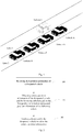
- the following vehicle may divide the signal space between the following vehicle and the designated vehicle into grid spaces (as shown by grids in Fig. 6 ) according to the received first position information of the designated vehicle and second position information of the following vehicle.
- the size or effective range of the grids is sent by the communication device at the network side to the following vehicle by way of configuration or pre-configuration, for example, there may be 5 ⁇ 10 ⁇ 2 signal space grids, the size of each grid is 1 m 3 ; and then the following vehicle can determine the grid spaces through which the beam passes from the divided grid spaces as the effective grid spaces (shown by the shaded parts in Fig. 6 ) in the beam sending direction according to the relative position information with the designated vehicle.
- the following vehicle receives and scans the beam in the effective grid spaces, so as to achieve the purpose of tracking the beam sent by the designated vehicle.
- the first position information may further include the high-definition dynamic map information of the designated vehicle.
- the grid division is performed on the signal space between the following vehicle and the designated vehicle, and the grid spaces through which the beam may pass are determined as the effective grid spaces, so that the following vehicle scans and receives the beam in the effective grid spaces, which can reduce the spatial range in which the following vehicle scans the beam effectively, thereby saving the energy consumption of the following vehicle and improving the efficiency of beam tracking.
- the network may be a cellular network or Wi-Fi network, etc.
- both the designated vehicle and the following vehicle are moving continuously, so the acquisition of the first position information and the second position information, the calculation of the reception angle, the adjustment of the beam receiving direction, and the determination of the effective grid space are also performed continuously.
- the beam tracking method is described above from the perspective of the following vehicle, and the beam tracking method will be described below from the perspective of the network side, i.e., the communication device.
- embodiments of the invention provides a beam tracking method applied to a communication device in the vehicle platooning.
- the processing procedure of the method is as follows.
- Step 701 receiving the first position information reported by a designated vehicle and the second position information reported by a following vehicle.
- the definitions of the designated vehicle, the first position information and the second position information are the same as those described in the foregoing method, and will not be repeated in order to save space.
- the first position information and the second position information received by the communication device may be periodically reported by the designated vehicle or the following vehicle in accordance with the pre-agreed reporting time, or may be reported by the designated vehicle or the following vehicle by way of response after the communication device sends an inquiry message to the designated vehicle or the following vehicle.
- the specific reporting method is not limited here.
- the designated vehicle or the following vehicle may report its position information to the communication device every 1 minute, 3 minutes, 5 minutes, etc., or the communication device sends the position inquiry information to the designated vehicle or the following vehicle when the communication device requires the designated vehicle or the following vehicle to report its position information according to the dynamic map information, and the designated vehicle or the following vehicle returns the response information carrying the first or second position information in response to the position inquiry information after receiving the position inquiry information.
- step 702 can be performed.
- Step 702 obtaining the relative position information of the designated vehicle and the following vehicle based on the first position information and the second position information.
- the specific method of obtaining the relative position information of the designated vehicle and the following vehicle is the same as the method in the above step 102, and will not be repeated here in order to save space.
- step 703 can be performed.
- Step 703 generating the configuration information of the following vehicle according to the relative position information, so that the following vehicle tracks a beam sent by the preceding vehicle according to the configuration information.
- the optimal grid is determined from a preset grid set according to the relative position information, so that the following vehicle can perform the gridding processing on the signal space between the designated vehicle and the following vehicle according to the size or range indicated by the optimal grid; and then the optimal grid is packaged in a preset data format to generate the configuration information.
- the preset grid set may be just a set with grid size of 0.5 m 3 , 1 m 3 , 1.5 m 3 , etc., or 0.2-0.5 m 3 , 0.5-1 m 3 , 1.0-1.5 m 3 , etc.
- the communication device determines, according to the relative position information of the designated vehicle and the following vehicle, that 5 ⁇ 10 ⁇ 2 signal space grids should be used between the designated vehicle and the following vehicle and that the size of each grid space is 1 m 3 which is determined as the optimal grid, and then packages the optimal grid in the preset data format to generate the configuration information, and sends the configuration information to the following vehicle, so that the following vehicle can perform the gridding processing on the signal space between the designated vehicle and the following vehicle according to the optimal grid in the configuration information.
- the grid size that best meets the requirements of the following vehicle is selected from the grid set preset by the communication device through the relative position information between the following vehicle and the designated vehicle, so that the signal space between the following vehicle and the designated vehicle can be reasonably divided into the grid spaces with better degree of recognition to thereby obtain the optimal grid, and the optimal grid is sent to the following vehicle, so that the following vehicle performs the grid division on the signal space between the following vehicle and the designated vehicle according to the optimal grid, and determines the grid spaces through which the beam may pass as the effective grid spaces. Then the following vehicle scans and receives the beam in the effective grid spaces, which can reduce the spatial range in which the following vehicle scans the beam effectively, thereby saving the energy consumption of the following vehicle and improving the efficiency of beam tracking.
- the motion relationship between the designated vehicle and the following vehicle is predicted on a dynamic map based on the first position information and the second position information; and then a reception angle at which the following vehicle receives the beam is generated based on the motion relationship and the relative position information to obtain the configuration information.
- the beam sent by the designated vehicle is tracked by using the reception angle configured by the communication device for the following vehicle.
- the calculation of the reception angle is done in the communication device, so that the software and hardware requirements for the following vehicle can be reduced effectively; and the communication device has a high-definition dynamic map with higher precision, so that it is more accurate when using the relative position information to calculate the reception angle, thereby improving the accuracy when the following vehicle tracks the beam sent by the designated vehicle effectively.
- the aforementioned communication device may specifically be a base station or an RSU.
- embodiments of the invention provide a beam tracking apparatus applied to a following vehicle in the vehicle platooning.
- the specific embodiments of the beam tracking method of the apparatus can refer to the description of the method embodiments of the following vehicle, and the repeated description thereof will be omitted here.
- the apparatus includes:
- the first position information and the second position information include:
- the obtaining unit 802 when obtaining the relative position information of the designated vehicle and the following vehicle based on the first position information and the second position information of the following vehicle, is configured to: calculate the vector angle of the following vehicle relative to the designated vehicle based on the longitude and latitude information in the first position information and the longitude and latitude information in the second position information to obtain the relative position information.
- the obtaining unit 802 is configured to:
- the tracking unit 803 is configured to: adjust the receiving direction in which the following vehicle receives the beam sent by the designated vehicle based on the second position information and the relative position information to track the beam.
- the tracking unit 803 is configured to:
- the tracking unit 803 is configured to:
- embodiments of the invention provide another beam tracking apparatus applied to a communication device in the vehicle platooning.
- the specific embodiments of the beam tracking method of the apparatus can refer to the description of the method embodiments of the communication device, and the repeated description thereof will be omitted here.
- the apparatus includes:
- the generating unit 903 is configured to:
- the generating unit 903 is configured to:
- the communication device is: a base station or an RSU.
- embodiments of the invention provide a beam tracking apparatus including: at least one processor, and a memory connected to the at least one processor; the memory stores instructions that can be executed by the at least one processor, and the at least one processor performs the beam tracking method as described above by executing the instructions stored in the memory.
- embodiments of the invention further provide a computer readable storage medium storing computer instructions.
- the computer instructions When the computer instructions are running on a computer, the computer is caused to perform the beam tracking method as described above when running on the computer.
- the relative position information of the designated vehicle and the following vehicle is determined according to the first position information and the second position information, and then the beam sent by the designated vehicle is tracked according to the relative position information. Since the designated vehicle is in front of the following vehicle in the vehicle platooning, the beam sent to the following vehicle must be sent backwards. Therefore, the following vehicle can effectively track the beam of the designated vehicle according to the relative position information with respect to the designated vehicle, thereby improving the reliability in receiving the beam sent by the designated vehicle; and there is no need to scan the beams at positions other than those indicated by the relative position information, so the time of beam discovery can further be reduced.
- embodiments of the invention may be provided as methods, systems or computer program products.
- the embodiments of the invention can take the form of hardware embodiments alone, software embodiments alone, or embodiments combining the software and hardware aspects.
- the embodiments of the invention can take the form of computer program products implemented on one or more computer usable storage mediums (including but not limited to magnetic disk memories, CD-ROMs, optical memories and the like) containing computer usable program codes therein.
- These computer program instructions can also be stored in a computer readable memory which is capable of guiding the computer or another programmable data processing device to operate in a particular way, so that the instructions stored in the computer readable memory produce a manufacture including the instruction apparatus which implements the functions specified in one or more processes of the flow charts and/or one or more blocks of the block diagrams.
- These computer program instructions can also be loaded onto the computer or another programmable data processing device, so that a series of operation steps are performed on the computer or another programmable device to produce the computer-implemented processing.
- the instructions executed on the computer or another programmable device provide steps for implementing the functions specified in one or more processes of the flow charts and/or one or more blocks of the block diagrams.
Landscapes
- Engineering & Computer Science (AREA)
- Computer Networks & Wireless Communication (AREA)
- Signal Processing (AREA)
- Physics & Mathematics (AREA)
- General Physics & Mathematics (AREA)
- Analytical Chemistry (AREA)
- Chemical & Material Sciences (AREA)
- Databases & Information Systems (AREA)
- Theoretical Computer Science (AREA)
- Remote Sensing (AREA)
- Data Mining & Analysis (AREA)
- General Engineering & Computer Science (AREA)
- Traffic Control Systems (AREA)
- Mobile Radio Communication Systems (AREA)
Abstract
Description
- This application claims priority of Chinese Patent Application No.
201810290858.4 - The invention relates to the field of vehicle to everything, and in particular to a beam tracking method and apparatus.
- In the enhanced Vehicle to Everything (eV2X), a plurality of vehicles with the same destination are organized into a fleet by using the vehicle platooning mechanism. The management and driving control for all vehicles in the fleet are realized by way of communications between the head vehicle and each of all other vehicles.
- As shown in
Fig. 1 , the vehicles A, B, C and D are driving in thelane 2, and forming a platooning fleet. The vehicle E is driving in thelane 1, and not forming a platooning fleet with the vehicles A∼D. - In related art, the head vehicle A in the platooning fleet usually sends relevant information to the following vehicles B, C and D in the unicast or multicast manner, to enable the following vehicles B, C and D to perform corresponding operations based on the relevant information sent by the head vehicle A, so that the following vehicles B, C and D keep consistent with the running trajectory of the head vehicle A.
- However, in the Vehicle to Everything, the relevant information sent by the head vehicle is usually sent in the form of beam signal. On one hand, the energy of the signal is sent to all directions in the space, so that the signal energy received by the following vehicles is only a part of the signal energy sent by the head vehicle, and on the other hand, the running speed of the vehicle is fast and the change in lane topology may also be quick, so that the signal energy received by the following vehicles will be further weaken. Since the signal energy is weaken, the reliability of receiving the signal from the preceding vehicle will be reduced, and the discovery time of the beam signal will be prolonged, so that the following vehicles cannot keep the same running trajectory as the head vehicle in time and accurately.
- Therefore, how to improve the reliability in receiving the beam signal from the preceding vehicle and find the beam signal quickly becomes a technical problem to be solved urgently in the Vehicle to Everything.
- The invention provides a beam tracking method and apparatus, so as to solve the technical problem in the prior art that the following vehicles have the low reliability in receiving beam signals and find the beam signals slowly during the vehicle platooning.
- In a first aspect, in order to solve the above technical problem, a beam tracking method provided by embodiments of the invention is applied to a following vehicle in the vehicle platooning. The technical solution is as follows:
- receiving first position information of a designated vehicle;
- obtaining relative position information of the designated vehicle and the following vehicle based on the first position information and second position information of the following vehicle;
- tracking a beam sent by the designated vehicle based on the relative position information.
- Since the designated vehicle is in front of the following vehicle in the vehicle platooning, the beam sent to the following vehicle must be sent backwards. Therefore, the following vehicle can effectively track the beam of the designated vehicle based on the relative position information with respect to the designated vehicle, thereby improving the reliability in receiving the beam sent by the designated vehicle; and there is no need to scan the beams at positions other than those indicated by the relative position information, so the time of beam discovery can further be reduced.
- Combining with the first aspect, in a first possible embodiment of the first aspect, the first position information and the second position information each includes:
- at least one of longitude and latitude information, lane information or height information;
- the height information is a height of the designated vehicle or the following vehicle relative to a preset horizontal position.
- Combining with the first possible embodiment of the first aspect, in a second possible embodiment of the first aspect, the obtaining relative position information of the designated vehicle and the following vehicle based on the first position information and second position information of the following vehicle, includes:
calculating a vector angle of the following vehicle relative to the designated vehicle based on longitude and latitude information in the first position information and longitude and latitude information in the second position information to obtain the relative position information. - Combining with the first possible embodiment of the first aspect, in a third possible embodiment of the first aspect, the obtaining relative position information of the designated vehicle and the following vehicle based on the first position information and second position information of the following vehicle, includes:
- predicting a motion trajectory of the designated vehicle based on the first position information and driving information of the designated vehicle; and
- calculating a relative motion relationship between the following vehicle and the designated vehicle according to the motion trajectory and the second position information to obtain the relative position information.
- Combining with the third possible embodiment of the first aspect, in a fourth possible embodiment of the first aspect, the tracking the beam sent by the designated vehicle based on the relative position information, includes:
adjusting a receiving direction in which the following vehicle receives the beam sent by the designated vehicle based on the second position information and the relative position information to track the beam. - Combining with the embodiments of the first aspect, in a fifth possible embodiment of the first aspect, the tracking the beam sent by the designated vehicle based on the relative position information, includes:
- tracking the beam sent by the designated vehicle at a configured reception angle based on the relative position information;
- the configured reception angle is a range of reception angles at which the following vehicle receives the beam and which is calculated by a communication device based on the relative position information and a motion relationship between the designated vehicle and the following vehicle, and the motion relationship is predicted on a dynamic map according to the first position information and the second position information.
- Combining with the embodiments of the first aspect, in a sixth possible embodiment of the first aspect, the tracking the beam sent by the designated vehicle based on the relative position information, includes:
- performing space grid division on a signal space between the first position information and the second position information in a signal space grid division way specified by a communication device to obtain grid spaces between the designated vehicle and the following vehicle;
- determining, from the grid spaces, a grid space through which the beam passes as an effective grid space according to a sending direction of the beam and the relative position information; and
- tracking the beam sent by the designated vehicle in the effective grid space.
- In a second aspect, embodiments of the invention provide another beam tracking method applied to a communication device in the vehicle platooning, including:
- receiving first position information reported by a designated vehicle and second position information reported by a following vehicle;
- obtaining relative position information of the designated vehicle and the following vehicle based on the first position information and the second position information; and
- generating configuration information of the following vehicle according to the relative position information, for the following vehicle to track a beam sent by a preceding vehicle according to the configuration information.
- Since the designated vehicle is in front of the following vehicle in the vehicle platooning, the beam sent to the following vehicle must be sent backwards. Therefore, the communication device can obtain the relative position information of the following vehicle and the designated vehicle according to the received first position information of the designated vehicle and second position information of the following vehicle, and can thus generate the configuration information of the following vehicle according to the relative position information, so that the following vehicle tracks the beam sent by the preceding vehicle according to the configuration information, and then the following vehicle implements the beam tracking of the designated vehicle, improving the reliability in receiving the beam sent by the designated vehicle; and the following vehicle does not need to scan the beams at positions other than those indicated by the relative position information, so the time for the following vehicle to find the beam can further be reduced.
- Combining with the embodiments of the second aspect, in a first possible embodiment of the second aspect, the generating configuration information of the following vehicle according to the relative position information, includes:
- determining an optimal grid from a preset grid set according to the relative position information, for the following vehicle to perform gridding processing on a signal space between the designated vehicle and the following vehicle according to a size or range indicated by the optimal grid; and
- packaging the optimal grid in a preset data format to generate the configuration information.
- Combining with the embodiments of the second aspect, in a second possible embodiment of the second aspect, the generating configuration information of the following vehicle according to the relative position information, includes:
- predicting a motion relationship between the designated vehicle and the following vehicle on a dynamic map based on the first position information and the second position information; and
- generating a reception angle at which the following vehicle receives the beam based on the motion relationship and the relative position information to obtain the configuration information.
- Combining with any one of the second aspect, the first possible embodiment of the second aspect, and the second possible embodiment of the second aspect, in a third possible embodiment of the second aspect, the communication device is:
a base station or an RSU. - In a third aspect, embodiments of the invention provide a beam tracking apparatus applied to a following vehicle in the vehicle platooning, including:
- a receiving unit configured to receive first position information of a designated vehicle;
- an obtaining unit configured to obtain relative position information of the designated vehicle and the following vehicle based on the first position information and second position information of the following vehicle; and
- a tracking unit configured to track a beam sent by the designated vehicle based on the relative position information.
- Combining with the embodiments of the third aspect, in a first possible embodiment of the third aspect, the first position information and the second position information each includes:
- at least one of longitude and latitude information, lane information or height information;
- the height information is a height of the designated vehicle or the following vehicle relative to a preset horizontal position.
- Combining with the first possible embodiment of the third aspect, in a second possible embodiment of the third aspect, the obtaining unit is configured to:
calculate a vector angle of the following vehicle relative to the designated vehicle based on longitude and latitude information in the first position information and longitude and latitude information in the second position information to obtain the relative position information. - Combining with the first possible embodiment of the third aspect, in a third possible embodiment of the third aspect, the obtaining unit is configured to:
- predict a motion trajectory of the designated vehicle based on the first position information and driving information of the designated vehicle; and
- calculate a relative motion relationship between the following vehicle and the designated vehicle according to the motion trajectory and the second position information to obtain the relative position information.
- Combining with the third possible embodiment of the third aspect, in a fourth possible embodiment of the third aspect, the tracking unit is configured to:
adjust a receiving direction in which the following vehicle receives the beam sent by the designated vehicle based on the second position information and the relative position information to track the beam. - Combining with the embodiments of the third aspect, in a fifth possible embodiment of the third aspect, the tracking unit is configured to:
- track the beam sent by the designated vehicle at a configured reception angle based on the relative position information;
- the configured reception angle is a range of reception angles at which the following vehicle receives the beam and which is calculated by a communication device based on the relative position information and a motion relationship between the designated vehicle and the following vehicle, and the motion relationship is predicted on a dynamic map according to the first position information and the second position information.
- Combining with the embodiments of the third aspect, in a sixth possible embodiment of the third aspect, the tracking unit is configured to:
- perform space grid division on a signal space between the first position information and the second position information in a signal space grid division way specified by a communication device to obtain grid spaces between the designated vehicle and the following vehicle;
- determine, from the grid spaces, a grid space through which the beam passes as an effective grid space according to a sending direction of the beam and the relative position information; and
- track the beam sent by the designated vehicle in the effective grid space.
- In a fourth aspect, embodiments of the invention further provide a beam tracking apparatus applied to a communication device in vehicle platooning, including:
- a receiving unit configured to receive first position information reported by a designated vehicle and second position information reported by a following vehicle;
- an obtaining unit configured to obtain relative position information of the designated vehicle and the following vehicle based on the first position information and the second position information; and
- a generating unit configured to generate configuration information of the following vehicle according to the relative position information, for the following vehicle to track a beam sent by a preceding vehicle according to the configuration information.
- Combining with the embodiments of the fourth aspect, in a first possible embodiment of the fourth aspect, the generating unit is configured to:
- determine an optimal grid from a preset grid set according to the relative position information, for the following vehicle to perform gridding processing on a signal space between the designated vehicle and the following vehicle according to a size or range indicated by the optimal grid; and
- package the optimal grid in a preset data format to generate the configuration information.
- Combining with the first possible embodiment of the fourth aspect, in a second possible embodiment of the fourth aspect, the generating unit is configured to:
- predict a motion relationship between the designated vehicle and the following vehicle on a dynamic map based on the first position information and the second position information; and
- generate a reception angle at which the following vehicle receives the beam based on the motion relationship and the relative position information to obtain the configuration information.
- Combining with any one of the fourth aspect, the first possible embodiment of the fourth aspect, and the second possible embodiment of the fourth aspect, in a third possible embodiment of the fourth aspect, the communication device is:
a base station or an RSU. - In a fifth aspect, embodiments of the invention further provide a beam tracking apparatus, including:
- at least one processor, and
- a memory connected to the at least one processor;
- the memory stores instructions that can be executed by the at least one processor, and the at least one processor performs the method as described in the above first or second aspect by executing the instructions stored in the memory.
- In a sixth aspect, embodiments of the invention further provide a computer readable storage medium storing computer instructions. When the computer instructions are running on a computer, the computer is caused to perform the method as described in the above first or second aspect.
- Through the technical solutions in one or more of the above embodiments of the invention, the embodiments of the invention have at least the following technical effects.
- In the embodiments provided by the invention, after the first position information of the designated vehicle and the second position information of the following vehicle are obtained in real time, the relative position information of the designated vehicle and the following vehicle is determined according to the first position information and the second position information, and then the beam sent by the designated vehicle is tracked according to the relative position information. Since the designated vehicle is in front of the following vehicle in the vehicle platooning, the beam sent to the following vehicle must be sent backwards. Therefore, the following vehicle can effectively track the beam of the designated vehicle according to the relative position information with respect to the designated vehicle, thereby improving the reliability in receiving the beam sent by the designated vehicle; and there is no need to scan the beams at positions other than those indicated by the relative position information, so the time of beam discovery can further be reduced.
-
-
Fig. 1 is a schematic diagram of a platooning fleet in the related art of the invention; -
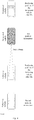
Fig. 2 is a schematic flow diagram of a beam tracking method provided by an embodiment of the invention; -
Fig. 3 is a first schematic diagram of a reception angle of a beam adjusted for the following vehicle provided by an embodiment of the invention; -
Fig. 4 is a second schematic diagram of a reception angle of a beam adjusted for the following vehicle provided by an embodiment of the invention to implement the beam tracking; -
Fig. 5 is a schematic diagram in which the following vehicle adjusts the receiving direction of the beam according to the reception angle configured at the network side to realize the beam tracking provided by an embodiment of the invention; -
Fig. 6 is a schematic diagram of implementing the beam tracking by receiving and scanning beams within an effective grid range provided by an embodiment of the invention; -
Fig. 7 is a schematic flow diagram of another beam tracking method provided by an embodiment of the invention; -
Fig. 8 is a schematic structural diagram of a beam tracking apparatus provided by an embodiment of the invention; -
Fig. 9 is a schematic structural diagram of another beam tracking apparatus provided by an embodiment of the invention. - Embodiments of invention provide a beam tracking solution, so as to solve the technical problem in the prior art that the following vehicles have the low reliability in receiving beam signals and find the beam signals slowly during the vehicle platooning.
- In order to solve the above-mentioned technical problem, the general idea of the technical solution in the embodiments of the present application is as follows.
- A beam tracking solution is provided, which includes: receiving first position information of a designated vehicle; obtaining relative position information of the designated vehicle and the following vehicle based on the first position information and second position information of the following vehicle; and tracking a beam sent by the designated vehicle based on the relative position information.
- In the above solution, after the first position information of the designated vehicle and the second position information of the following vehicle are obtained, the relative position information of the designated vehicle and the following vehicle is determined according to the first position information and the second position information, and then the beam sent by the designated vehicle is tracked according to the relative position information. Since the designated vehicle is in front of the following vehicle in the vehicle platooning, the beam sent to the following vehicle must be sent backwards. Therefore, the following vehicle can effectively track the beam of the designated vehicle according to the relative position information with respect to the designated vehicle, thereby improving the reliability in receiving the beam sent by the designated vehicle; and there is no need to scan the beams at positions other than those indicated by the relative position information, so the time of beam discovery can further be reduced.
- In order for better understanding of the above-mentioned technical solutions, the technical solutions of the invention will be illustrated below in details by way of the drawings and specific embodiments, and it should be understood that the embodiments of the invention and the specific features in the embodiments are intended to illustrate the technical solutions of the invention in details but not limit the technical solutions of the invention, and the embodiments of the invention and the specific features in the embodiments can be combined with each other without collision.
- Please referring to
Fig. 2 , embodiments of the invention provide a beam tracking method applied to a following vehicle in the vehicle platooning. The processing procedure of the method is as follows. - Step 201: receiving first position information of a designated vehicle.
- Here, the designated vehicle refers to a vehicle driving before the following vehicle, which may be the head vehicle or a preceding vehicle. Which specific vehicle before the following vehicle is not limited here. In actual applications, the designated vehicle may be preset as required, or one of the vehicles before the following vehicle is determined as the designated vehicle according to the preset strategy.
- The first position information and the second position information may be at least one of the longitude and latitude information, lane information or height information. The height information is the height of the designated vehicle or the following vehicle relative to a preset horizontal position.
- The designated vehicle and the following vehicle can obtain their position information (such as longitude and latitude, height information, lane information of the lane where they are located, etc.) through the Global Navigation Satellite System (GNSS).
- The global navigation satellite system may be Beidou system, Global Positioning System (GPS), Glonass satellite navigation system (GLONASS), Galileo satellite navigation system (Galileo), etc.
- The following vehicle may obtain the first position information of the designated vehicle regularly or irregularly, or may obtain the first position information of the designated vehicle by means of inquire-response. The way in which the following vehicle obtains the first position information may be to communicate with the designated vehicle directly, or may be to obtain the first position information of the designated vehicle indirectly through the base station or RSU at the network side. There is no limitation here on which way is specifically used to obtain the first position information.
- After the following vehicle obtains the first position information of the designated vehicle, step 202 can be performed.
- Step 202: obtaining relative position information of the designated vehicle and the following vehicle based on the first position information and second position information of the following vehicle.
- Specifically, there are several ways to obtain the relative position information of the designated vehicle and the following vehicle.
- In a first way, the vector angle of the following vehicle relative to the designated vehicle can be calculated based on the longitude and latitude information in the first position information and the longitude and latitude information in the second position information to obtain the relative position information.
- For example, assuming that the longitude and latitude coordinates of the designated vehicle are (116.329422, 39.362288) and the longitude and latitude coordinates of the following vehicle are (116.329709, 39.361228), then it can be calculated that the designated vehicle is in the front left of the following vehicle by 15 degrees at the distance of 120 meters and is driving to the north along the lane. Here the vector angle needs to be 15° in the front left, so 15° in the front left is used as the relative position information.
- Through the longitude and latitude information of the designated vehicle and the following vehicle, the vector angle of the following vehicle and the designated vehicle can be calculated quickly and accurately, and then the relative position information of the following vehicle and the designated vehicle can be obtained quickly. Since it is very convenient to obtain the longitude and latitude which are not restricted by region, the method of obtaining the relative position information through the longitude and latitude information can be widely used all over the world.
- In a second way, the motion trajectory of the designated vehicle can be predicted based on the first position information and the driving information of the designated vehicle; and a relative motion relationship between the following vehicle and the designated vehicle is calculated according to the motion trajectory and the second position information to obtain the relative position information.
- Here, the driving information may include driving speed, acceleration, direction, and so on.
- For example: the first position information of the designated vehicle is (116.329422, 39.362288), and the driving information is driving to the north at the constant driving speed of 120 km/h. Then the motion trajectory of the designated vehicle in a period of time in the future can be predicted, and then according to the predicted motion trajectory, the second position information (116.329422, 39.360288) of the following vehicle and the driving information of the following vehicle (for example, also driving to the north at the constant driving speed of 120 km/h), the relative motion relationship between the following vehicle and the designated vehicle can be calculated as driving to the north with keeping the vehicle distance of 222 meters, to thereby obtain the relative position information of the following vehicle and the designated vehicle.
- The motion trajectory of the designated vehicle is predicted through the first position information and driving information of the designated vehicle, and the relative motion relationship between the following vehicle and the designated vehicle is calculated according to the motion trajectory of the designated vehicle and the second position information of the following vehicle. The following vehicle may obtain the relative position relationship with the designated vehicle in advance, and then adjusts the beam for tracking the designated vehicle according to the relative position relationship, making the tracking beam more intelligent.
- After the relative position information of the following vehicle and the designated vehicle is obtained,
step 203 can be performed. - Step 203: tracking a beam sent by the designated vehicle based on the relative position information.
- Specifically, the tracking of the beam sent by the designated vehicle can be implemented by the following vehicle in the following ways.
- In a first way: the receiving direction in which the following vehicle receives the beam sent by the designated vehicle is adjusted based on the second position information and the relative position information, to track the beam.
- For example, referring to
Fig. 3 , the following vehicle calculates the direction from the following vehicle to the designated vehicle through the first position information and the second position information, then determines the vector angle between the following vehicle and the designated vehicle, determines the reception angle of the beam according to the vector angle, and adjusts the receiving direction in which the following vehicle receives the beam sent by the designated vehicle in the angle range indicated by the reception angle. For example, the reception angle may be obtained by taking the line of a point position of the following vehicle and a point position of the designated vehicle as the axis and multiplying the vector angle by a preset proportionality coefficient as the included angle. - Referring to
Fig. 4 , it is assumed that the longitude and latitude coordinates in the first position information of the designated vehicle are (116.329422, 39.362288), the designated vehicle is driving to the north along the lane, and the driving information is driving at an average speed of 120 km/h. The designated vehicle can send the first position information to the following vehicle by way of broadcasting, and the first position information may further carry the dynamic map information of the designated vehicle. - The following vehicle can predict the motion trajectory of the designated vehicle as driving to the north at the speed of 120 km/h along the lane at the position (116.329422, 39.362288) according to the first position information and the driving information. For example, it can be predicted that the designated vehicle will reach a position in front of the first position information (116.329422, 39.362288) at the distance of 333 meters after 10s, and then according to the motion trajectory of the designated vehicle and the longitude and latitude (116.329709, 39.361228) in the second position information of the following vehicle, the relative motion relationship between the following vehicle and the designated vehicle can be calculated as: the designated vehicle is driving to the north with keeping 222 meters in front of the following vehicle, to thereby obtain the relative position information of the following vehicle and the designated vehicle. Since this section of the road has no curve, there is no need to change the reception angle of the following vehicle, that is, the following vehicle continues receiving and scanning the beam of the designated vehicle at the latest adjusted reception angle to track the beam sent by the designated vehicle.
- The following vehicle can determine the direction between the following vehicle and the designated vehicle quickly through the second position information and relative position information, and then adjust the receiving direction of the beam in time according to the change in their directions, so that the following vehicle can track the beam sent by the designated vehicle quickly and timely.
- In a second way: the beam sent by the designated vehicle is tracked at a configured reception angle based on the relative position information. The configured reception angle is a range of reception angles at which the following vehicle receives the beam and which is calculated by a communication device based on the relative position information and a motion relationship between the designated vehicle and the following vehicle, and the motion relationship is predicted on a dynamic map according to the first position information and the second position information.
- Here, the communication device may be a base station or a Road Side Unit (RSU).
- Before the following vehicle tracks the beam sent by the designated vehicle at the configured reception angle, the following vehicle and the designated vehicle can report their position information to the communication device regularly or irregularly, so that the communication device predicts the motion relationship between the designated vehicle and the following vehicle on the dynamic map according to the first position information of the designated vehicle and the second position information of the following vehicle. The motion relationship is, for example, as follows: the designated vehicle and the following vehicle move on which road at what speeds and accelerations, or what speed and acceleration of the following vehicle relative to the designated vehicle, etc.; and then the communication device can calculate the range of reception angles at which the following vehicle receives the beam sent by the designated vehicle according to the motion relationship between the designated vehicle and the following vehicle and the relative position information, and then send the range of reception angles to the following vehicle.
- Referring to
Fig. 5 , after receiving the range of reception angles sent by the communication device, the following vehicle adjusts the beam reception angle in the range of reception angles according to the relative position information, so as to track the beam information sent by the designated vehicle. - The beam sent by the designated vehicle is tracked by using the reception angle configured by the communication device for the following vehicle. The calculation of the reception angle is done in the communication device, so that the software and hardware requirements for the following vehicle can be reduced effectively; and the communication device has a high-definition dynamic map with higher precision, so that it is more accurate when using the relative position information to calculate the reception angle, thereby improving the accuracy when the following vehicle tracks the beam sent by the designated vehicle effectively.
- In a third way: firstly the space grid division is performed on the signal space between the first position information and the second position information in a signal space grid division way specified by a communication device to obtain the grid spaces between the designated vehicle and the following vehicle; then a grid space through which the beam passes is determined from the grid spaces as the effective grid space according to the sending direction of the beam and the relative position information; and finally the beam sent by the designated vehicle is tracked in the effective grid space.
- Here, the communication device may be a base station or a road side unit.
- Referring to
Fig. 6 , the following vehicle may divide the signal space between the following vehicle and the designated vehicle into grid spaces (as shown by grids inFig. 6 ) according to the received first position information of the designated vehicle and second position information of the following vehicle. The size or effective range of the grids is sent by the communication device at the network side to the following vehicle by way of configuration or pre-configuration, for example, there may be 5×10×2 signal space grids, the size of each grid is 1 m3; and then the following vehicle can determine the grid spaces through which the beam passes from the divided grid spaces as the effective grid spaces (shown by the shaded parts inFig. 6 ) in the beam sending direction according to the relative position information with the designated vehicle. The following vehicle receives and scans the beam in the effective grid spaces, so as to achieve the purpose of tracking the beam sent by the designated vehicle. The first position information may further include the high-definition dynamic map information of the designated vehicle. - The grid division is performed on the signal space between the following vehicle and the designated vehicle, and the grid spaces through which the beam may pass are determined as the effective grid spaces, so that the following vehicle scans and receives the beam in the effective grid spaces, which can reduce the spatial range in which the following vehicle scans the beam effectively, thereby saving the energy consumption of the following vehicle and improving the efficiency of beam tracking.
- It should be understood that this method may be applicable to the nodes within the network coverage, and may also be applicable to the nodes outside the network coverage by way of network pre-configuration. The network may be a cellular network or Wi-Fi network, etc.
- It should be understood that, in each of the embodiments implementing the beam tracking in the above first to third ways, both the designated vehicle and the following vehicle are moving continuously, so the acquisition of the first position information and the second position information, the calculation of the reception angle, the adjustment of the beam receiving direction, and the determination of the effective grid space are also performed continuously.
- The beam tracking method is described above from the perspective of the following vehicle, and the beam tracking method will be described below from the perspective of the network side, i.e., the communication device.
- Please referring to
Fig. 7 , embodiments of the invention provides a beam tracking method applied to a communication device in the vehicle platooning. The processing procedure of the method is as follows. - Step 701: receiving the first position information reported by a designated vehicle and the second position information reported by a following vehicle.
- Here, the definitions of the designated vehicle, the first position information and the second position information are the same as those described in the foregoing method, and will not be repeated in order to save space.
- The first position information and the second position information received by the communication device may be periodically reported by the designated vehicle or the following vehicle in accordance with the pre-agreed reporting time, or may be reported by the designated vehicle or the following vehicle by way of response after the communication device sends an inquiry message to the designated vehicle or the following vehicle. The specific reporting method is not limited here.
- For example, the designated vehicle or the following vehicle may report its position information to the communication device every 1 minute, 3 minutes, 5 minutes, etc., or the communication device sends the position inquiry information to the designated vehicle or the following vehicle when the communication device requires the designated vehicle or the following vehicle to report its position information according to the dynamic map information, and the designated vehicle or the following vehicle returns the response information carrying the first or second position information in response to the position inquiry information after receiving the position inquiry information.
- After the communication device obtains the first position information and the second position information, step 702 can be performed.
- Step 702: obtaining the relative position information of the designated vehicle and the following vehicle based on the first position information and the second position information.
- The specific method of obtaining the relative position information of the designated vehicle and the following vehicle is the same as the method in the above step 102, and will not be repeated here in order to save space.
- After the relative position information is obtained,
step 703 can be performed. - Step 703: generating the configuration information of the following vehicle according to the relative position information, so that the following vehicle tracks a beam sent by the preceding vehicle according to the configuration information.
- There may be two ways to generate the configuration information of the following vehicle according to the relative position information.
- In a first way, firstly the optimal grid is determined from a preset grid set according to the relative position information, so that the following vehicle can perform the gridding processing on the signal space between the designated vehicle and the following vehicle according to the size or range indicated by the optimal grid; and then the optimal grid is packaged in a preset data format to generate the configuration information.
- Here, the preset grid set may be just a set with grid size of 0.5 m3, 1 m3, 1.5 m3, etc., or 0.2-0.5 m3, 0.5-1 m3, 1.0-1.5 m3, etc.
- For example, the communication device determines, according to the relative position information of the designated vehicle and the following vehicle, that 5×10×2 signal space grids should be used between the designated vehicle and the following vehicle and that the size of each grid space is 1 m3 which is determined as the optimal grid, and then packages the optimal grid in the preset data format to generate the configuration information, and sends the configuration information to the following vehicle, so that the following vehicle can perform the gridding processing on the signal space between the designated vehicle and the following vehicle according to the optimal grid in the configuration information.
- The grid size that best meets the requirements of the following vehicle is selected from the grid set preset by the communication device through the relative position information between the following vehicle and the designated vehicle, so that the signal space between the following vehicle and the designated vehicle can be reasonably divided into the grid spaces with better degree of recognition to thereby obtain the optimal grid, and the optimal grid is sent to the following vehicle, so that the following vehicle performs the grid division on the signal space between the following vehicle and the designated vehicle according to the optimal grid, and determines the grid spaces through which the beam may pass as the effective grid spaces. Then the following vehicle scans and receives the beam in the effective grid spaces, which can reduce the spatial range in which the following vehicle scans the beam effectively, thereby saving the energy consumption of the following vehicle and improving the efficiency of beam tracking.
- In a second way, firstly the motion relationship between the designated vehicle and the following vehicle is predicted on a dynamic map based on the first position information and the second position information; and then a reception angle at which the following vehicle receives the beam is generated based on the motion relationship and the relative position information to obtain the configuration information.
- The beam sent by the designated vehicle is tracked by using the reception angle configured by the communication device for the following vehicle. The calculation of the reception angle is done in the communication device, so that the software and hardware requirements for the following vehicle can be reduced effectively; and the communication device has a high-definition dynamic map with higher precision, so that it is more accurate when using the relative position information to calculate the reception angle, thereby improving the accuracy when the following vehicle tracks the beam sent by the designated vehicle effectively.
- Since the processing method of the communication device here is the same as that of the communication device in
Fig. 5 , it will not be repeated here. - The aforementioned communication device may specifically be a base station or an RSU.
- Based on the same inventive concept, embodiments of the invention provide a beam tracking apparatus applied to a following vehicle in the vehicle platooning. The specific embodiments of the beam tracking method of the apparatus can refer to the description of the method embodiments of the following vehicle, and the repeated description thereof will be omitted here. Referring to
Fig. 8 , the apparatus includes: - a receiving
unit 801 configured to receive the first position information of a designated vehicle; - an obtaining
unit 802 configured to obtain the relative position information of the designated vehicle and the following vehicle based on the first position information and the second position information of the following vehicle; - a
tracking unit 803 configured to track a beam sent by the designated vehicle according to the relative position information. - Optionally, the first position information and the second position information include:
- at least one of longitude and latitude information, lane information or height information;
- the height information is the height of the designated vehicle or the following vehicle relative to a preset horizontal position.
- Optionally, when obtaining the relative position information of the designated vehicle and the following vehicle based on the first position information and the second position information of the following vehicle, the obtaining
unit 802 is configured to:
calculate the vector angle of the following vehicle relative to the designated vehicle based on the longitude and latitude information in the first position information and the longitude and latitude information in the second position information to obtain the relative position information. - Optionally, the obtaining
unit 802 is configured to: - predict the motion trajectory of the designated vehicle based on the first position information and the driving information of the designated vehicle; and
- calculate a relative motion relationship between the following vehicle and the designated vehicle according to the motion trajectory and the second position information to obtain the relative position information.
- Optionally, the
tracking unit 803 is configured to:
adjust the receiving direction in which the following vehicle receives the beam sent by the designated vehicle based on the second position information and the relative position information to track the beam. - Optionally, the
tracking unit 803 is configured to: - track the beam sent by the designated vehicle at a configured reception angle based on the relative position information;
- the configured reception angle is a range of reception angles at which the following vehicle receives the beam and which is calculated by a communication device based on the relative position information and a motion relationship between the designated vehicle and the following vehicle, and the motion relationship is predicted on a dynamic map according to the first position information and the second position information.
- Optionally, the
tracking unit 803 is configured to: - perform the space grid division on the signal space between the first position information and the second position information in a signal space grid division way specified by a communication device to obtain grid spaces between the designated vehicle and the following vehicle;
- determine, from the grid spaces, a grid space through which the beam passes as an effective grid space according to the sending direction of the beam and the relative position information; and
- track the beam sent by the designated vehicle in the effective grid space.
- Based on the same inventive concept, embodiments of the invention provide another beam tracking apparatus applied to a communication device in the vehicle platooning. The specific embodiments of the beam tracking method of the apparatus can refer to the description of the method embodiments of the communication device, and the repeated description thereof will be omitted here. Referring to
Fig. 9 , the apparatus includes: - a receiving
unit 901 configured to receive the first position information reported by a designated vehicle and the second position information reported by a following vehicle; - an obtaining
unit 902 configured to obtain the relative position information of the designated vehicle and the following vehicle based on the first position information and the second position information; and - a
generating unit 903 configured to generate the configuration information of the following vehicle according to the relative position information, so that the following vehicle tracks a beam sent by the preceding vehicle according to the configuration information. - Optionally, the generating
unit 903 is configured to: - determine an optimal grid from a preset grid set according to the relative position information, so that the following vehicle can perform gridding processing on the signal space between the designated vehicle and the following vehicle according to the size or range indicated by the optimal grid; and
- package the optimal grid in a preset data format to generate the configuration information.
- Optionally, the generating
unit 903 is configured to: - predict a motion relationship between the designated vehicle and the following vehicle on a dynamic map based on the first position information and the second position information; and
- generate the reception angle at which the following vehicle receives the beam based on the motion relationship and the relative position information to obtain the configuration information.
- Optionally, the communication device is:
a base station or an RSU. - Based on the same inventive concept, embodiments of the invention provide a beam tracking apparatus including: at least one processor, and
a memory connected to the at least one processor;
the memory stores instructions that can be executed by the at least one processor, and the at least one processor performs the beam tracking method as described above by executing the instructions stored in the memory. - Based on the same inventive concept, embodiments of the invention further provide a computer readable storage medium storing computer instructions. When the computer instructions are running on a computer, the computer is caused to perform the beam tracking method as described above when running on the computer.
- In the embodiments provided by the invention, after the first position information of the designated vehicle and the second position information of the following vehicle are obtained in real time, the relative position information of the designated vehicle and the following vehicle is determined according to the first position information and the second position information, and then the beam sent by the designated vehicle is tracked according to the relative position information. Since the designated vehicle is in front of the following vehicle in the vehicle platooning, the beam sent to the following vehicle must be sent backwards. Therefore, the following vehicle can effectively track the beam of the designated vehicle according to the relative position information with respect to the designated vehicle, thereby improving the reliability in receiving the beam sent by the designated vehicle; and there is no need to scan the beams at positions other than those indicated by the relative position information, so the time of beam discovery can further be reduced.
- It should be understood by those skilled in the art that the embodiments of the invention may be provided as methods, systems or computer program products. Thus the embodiments of the invention can take the form of hardware embodiments alone, software embodiments alone, or embodiments combining the software and hardware aspects. Also the embodiments of the invention can take the form of computer program products implemented on one or more computer usable storage mediums (including but not limited to magnetic disk memories, CD-ROMs, optical memories and the like) containing computer usable program codes therein.
- The embodiments of the invention are described by reference to the flow charts and/or the block diagrams of the methods, the devices (systems) and the computer program products according to the embodiments of the invention. It should be understood that each process and/or block in the flow charts and/or the block diagrams, and a combination of processes and/or blocks in the flow charts and/or the block diagrams can be implemented by the computer program instructions. These computer program instructions can be provided to a general-purpose computer, a dedicated computer, an embedded processor, or a processor of another programmable data processing device to produce a machine, so that an apparatus for implementing the functions specified in one or more processes of the flow charts and/or one or more blocks of the block diagrams is produced by the instructions executed by the computer or the processor of another programmable data processing device.
- These computer program instructions can also be stored in a computer readable memory which is capable of guiding the computer or another programmable data processing device to operate in a particular way, so that the instructions stored in the computer readable memory produce a manufacture including the instruction apparatus which implements the functions specified in one or more processes of the flow charts and/or one or more blocks of the block diagrams.
- These computer program instructions can also be loaded onto the computer or another programmable data processing device, so that a series of operation steps are performed on the computer or another programmable device to produce the computer-implemented processing. Thus the instructions executed on the computer or another programmable device provide steps for implementing the functions specified in one or more processes of the flow charts and/or one or more blocks of the block diagrams.
- Evidently those skilled in the art can make various modifications and variations to the invention without departing from the spirit and scope of the invention. Thus the invention is also intended to encompass these modifications and variations therein as long as these modifications and variations come into the scope of the claims of the invention and their equivalents.
Claims (24)
- A beam tracking method, applied to a following vehicle in vehicle platooning and comprising:receiving first position information of a designated vehicle;obtaining relative position information of the designated vehicle and the following vehicle based on the first position information and second position information of the following vehicle;tracking a beam sent by the designated vehicle based on the relative position information.
- The method of claim 1, wherein the first position information and the second position information each comprises at least one of:longitude and latitude information;lane information; orheight information;wherein the height information is a height of the designated vehicle or the following vehicle relative to a preset horizontal position.
- The method of claim 2, wherein the obtaining relative position information of the designated vehicle and the following vehicle based on the first position information and second position information of the following vehicle, comprises:
calculating a vector angle of the following vehicle relative to the designated vehicle based on longitude and latitude information in the first position information and longitude and latitude information in the second position information to obtain the relative position information. - The method of claim 2, wherein the obtaining relative position information of the designated vehicle and the following vehicle based on the first position information and second position information of the following vehicle, comprises:predicting a motion trajectory of the designated vehicle based on the first position information and driving information of the designated vehicle; andcalculating a relative motion relationship between the following vehicle and the designated vehicle according to the motion trajectory and the second position information to obtain the relative position information.
- The method of claim 4, wherein the tracking the beam sent by the designated vehicle based on the relative position information, comprises:
adjusting a receiving direction in which the following vehicle receives the beam sent by the designated vehicle based on the second position information and the relative position information to track the beam. - The method of claim 1, wherein the tracking the beam sent by the designated vehicle based on the relative position information, comprises:tracking the beam sent by the designated vehicle at a configured reception angle based on the relative position information;wherein the configured reception angle is a range of reception angles at which the following vehicle receives the beam and which is calculated by a communication device based on the relative position information and a motion relationship between the designated vehicle and the following vehicle, and the motion relationship is predicted on a dynamic map according to the first position information and the second position information.
- The method of claim 1, wherein the tracking the beam sent by the designated vehicle based on the relative position information, comprises:performing space grid division on a signal space between the first position information and the second position information in a signal space grid division way specified by a communication device to obtain grid spaces between the designated vehicle and the following vehicle;determining, from the grid spaces, a grid space through which the beam passes as an effective grid space according to a sending direction of the beam and the relative position information; andtracking the beam sent by the designated vehicle in the effective grid space.
- A beam tracking method, applied to a communication device in vehicle platooning and comprising:receiving first position information reported by a designated vehicle and second position information reported by a following vehicle;obtaining relative position information of the designated vehicle and the following vehicle based on the first position information and the second position information; andgenerating configuration information of the following vehicle according to the relative position information, for the following vehicle to track a beam sent by a preceding vehicle according to the configuration information.
- The method of claim 8, wherein the generating configuration information of the following vehicle according to the relative position information, comprises:determining an optimal grid from a preset grid set according to the relative position information, for the following vehicle to perform gridding processing on a signal space between the designated vehicle and the following vehicle according to a size or range indicated by the optimal grid; andpackaging the optimal grid in a preset data format to generate the configuration information.
- The method of claim 8, wherein the generating configuration information of the following vehicle according to the relative position information, comprises:predicting a motion relationship between the designated vehicle and the following vehicle on a dynamic map based on the first position information and the second position information; andgenerating a reception angle at which the following vehicle receives the beam based on the motion relationship and the relative position information to obtain the configuration information.
- The method of any one of claims 8-10, wherein the communication device is:a base station; ora Road Side Unit, RSU.
- A beam tracking apparatus, applied to a following vehicle in vehicle platooning and comprising:a receiving unit configured to receive first position information of a designated vehicle;an obtaining unit configured to obtain relative position information of the designated vehicle and the following vehicle based on the first position information and second position information of the following vehicle; anda tracking unit configured to track a beam sent by the designated vehicle based on the relative position information.
- The apparatus of claim 12, wherein the first position information and the second position information each comprises at least one of:longitude and latitude information;lane information; orheight information;wherein the height information is a height of the designated vehicle or the following vehicle relative to a preset horizontal position.
- The apparatus of claim 13, wherein the obtaining unit is configured to:
calculate a vector angle of the following vehicle relative to the designated vehicle based on longitude and latitude information in the first position information and longitude and latitude information in the second position information to obtain the relative position information. - The apparatus of claim 13, wherein the obtaining unit is configured to:predict a motion trajectory of the designated vehicle based on the first position information and driving information of the designated vehicle; andcalculate a relative motion relationship between the following vehicle and the designated vehicle according to the motion trajectory and the second position information to obtain the relative position information.
- The apparatus of claim 15, wherein the tracking unit is configured to:
adjust a receiving direction in which the following vehicle receives the beam sent by the designated vehicle based on the second position information and the relative position information to track the beam. - The apparatus of claim 12, wherein the tracking unit is configured to:track the beam sent by the designated vehicle at a configured reception angle based on the relative position information;wherein the configured reception angle is a range of reception angles at which the following vehicle receives the beam and which is calculated by a communication device based on the relative position information and a motion relationship between the designated vehicle and the following vehicle, and the motion relationship is predicted on a dynamic map according to the first position information and the second position information.
- The apparatus of claim 12, wherein the tracking unit is configured to:perform space grid division on a signal space between the first position information and the second position information in a signal space grid division way specified by a communication device to obtain grid spaces between the designated vehicle and the following vehicle;determine, from the grid spaces, a grid space through which the beam passes as an effective grid space according to a sending direction of the beam and the relative position information; andtrack the beam sent by the designated vehicle in the effective grid space.
- A beam tracking apparatus, applied to a communication device in vehicle platooning and comprising:a receiving unit configured to receive first position information reported by a designated vehicle and second position information reported by a following vehicle;an obtaining unit configured to obtain relative position information of the designated vehicle and the following vehicle based on the first position information and the second position information; anda generating unit configured to generate configuration information of the following vehicle according to the relative position information, for the following vehicle to track a beam sent by a preceding vehicle according to the configuration information.
- The apparatus of claim 19, wherein the generating unit is configured to:determine an optimal grid from a preset grid set according to the relative position information, for the following vehicle to perform gridding processing on a signal space between the designated vehicle and the following vehicle according to a size or range indicated by the optimal grid; andpackage the optimal grid in a preset data format to generate the configuration information.
- The apparatus of claim 19, wherein the generating unit is configured to:predict a motion relationship between the designated vehicle and the following vehicle on a dynamic map based on the first position information and the second position information; andgenerate a reception angle at which the following vehicle receives the beam based on the motion relationship and the relative position information to obtain the configuration information.
- The apparatus of any one of claims 19-21, wherein the communication device is:a base station; oran RSU.
- A beam tracking apparatus, comprising:at least one processor; anda memory connected to the at least one processor;wherein the memory stores instructions that can be executed by the at least one processor, and the at least one processor performs the method of any one of claims 1-11 by executing the instructions stored in the memory.
- A computer readable storage medium storing computer instructions, wherein when the computer instructions are running on a computer, the computer is caused to perform the method of any one of claims 1-11.
Applications Claiming Priority (2)
| Application Number | Priority Date | Filing Date | Title |
|---|---|---|---|
| CN201810290858.4A CN110366092A (en) | 2018-04-03 | 2018-04-03 | A kind of method and device of wave beam tracking |
| PCT/CN2019/080893 WO2019192436A1 (en) | 2018-04-03 | 2019-04-01 | Beam tracking method and apparatus |
Publications (2)
| Publication Number | Publication Date |
|---|---|
| EP3780663A1 true EP3780663A1 (en) | 2021-02-17 |
| EP3780663A4 EP3780663A4 (en) | 2021-03-03 |
Family
ID=68099822
Family Applications (1)
| Application Number | Title | Priority Date | Filing Date |
|---|---|---|---|
| EP19781868.5A Withdrawn EP3780663A4 (en) | 2018-04-03 | 2019-04-01 | Beam tracking method and apparatus |
Country Status (4)
| Country | Link |
|---|---|
| US (1) | US12047154B2 (en) |
| EP (1) | EP3780663A4 (en) |
| CN (1) | CN110366092A (en) |
| WO (1) | WO2019192436A1 (en) |
Families Citing this family (1)
| Publication number | Priority date | Publication date | Assignee | Title |
|---|---|---|---|---|
| CN112738764B (en) * | 2020-12-28 | 2021-12-24 | 北京邮电大学 | A broadband millimeter-wave beam tracking method based on vehicle trajectory cognition |
Family Cites Families (9)
| Publication number | Priority date | Publication date | Assignee | Title |
|---|---|---|---|---|
| DE19916855A1 (en) | 1999-04-14 | 2000-10-26 | Heinz Lindenmeier | Radio telephone system with group antenna for vehicles |
| KR101326889B1 (en) * | 2011-11-07 | 2013-11-11 | 현대자동차주식회사 | A method and system to control relative position among vehicles using dgps mobile reference station |
| KR102034722B1 (en) * | 2015-03-19 | 2019-10-21 | 현대자동차주식회사 | Vehicle, communicating method thereof and wireless communication apparatus therein |
| WO2016200302A1 (en) * | 2015-06-10 | 2016-12-15 | Telefonaktiebolaget Lm Ericsson (Publ) | A method and an apparatus for determining a beam to direct a signal to be transmitted to a user equipment |
| KR101709076B1 (en) * | 2015-11-24 | 2017-02-22 | 현대자동차주식회사 | Antenna apparatus and vehicle having the same |
| CN107135021B (en) * | 2016-02-29 | 2021-10-15 | 中兴通讯股份有限公司 | An uplink beam tracking method and corresponding terminal and base station |
| US10017179B2 (en) | 2016-06-06 | 2018-07-10 | GM Global Technology Operations LLC | Method for optimizing inter-vehicle distance and equitably sharing fuel benefits in a vehicle platoon |
| US9666067B1 (en) * | 2016-08-30 | 2017-05-30 | Allstate Insurance Company | Vehicle turn detection |
| CN109792275A (en) * | 2016-09-26 | 2019-05-21 | 瑞典爱立信有限公司 | Beam forming in wireless communication system |
-
2018
- 2018-04-03 CN CN201810290858.4A patent/CN110366092A/en active Pending
-
2019
- 2019-04-01 EP EP19781868.5A patent/EP3780663A4/en not_active Withdrawn
- 2019-04-01 WO PCT/CN2019/080893 patent/WO2019192436A1/en not_active Ceased
- 2019-04-01 US US17/043,630 patent/US12047154B2/en active Active
Also Published As
| Publication number | Publication date |
|---|---|
| US20210021328A1 (en) | 2021-01-21 |
| WO2019192436A1 (en) | 2019-10-10 |
| CN110366092A (en) | 2019-10-22 |
| US12047154B2 (en) | 2024-07-23 |
| EP3780663A4 (en) | 2021-03-03 |
Similar Documents
| Publication | Publication Date | Title |
|---|---|---|
| US11092696B2 (en) | Grouping for efficient cooperative positioning calculations | |
| KR101545722B1 (en) | Apparatus for controlling complementing position of vehicle, and system and method for complementing position of vehicle with the said apparatus | |
| KR101755944B1 (en) | Autonomous driving method and system for determing position of car graft on gps, uwb and v2x | |
| Adegoke et al. | Infrastructure Wi-Fi for connected autonomous vehicle positioning: A review of the state-of-the-art | |
| US10098014B1 (en) | Beam alignment using shared driving intention for vehicular mmWave communication | |
| US11041934B2 (en) | Precise positioning using millimeter wave narrow beamforming | |
| KR101806029B1 (en) | System and method for detecting position of vehicle using gps and uwb | |
| US20170131406A1 (en) | Differential Positioning Method Based on Intelligent Vehicle Infrastructure Cooperative System and Intelligent Vehicle Infrastructure Cooperative System | |
| EP3687195B1 (en) | Adaptive beamwidth control for millimeter wave v2x communications | |
| Qin et al. | Vehicles on RFID: Error-cognitive vehicle localization in GPS-less environments | |
| US12307902B2 (en) | Cluster-based approach to positioning of vehicles in vehicle platooning or autonomous trucking | |
| Eckelmann et al. | V2v-communication, lidar system and positioning sensors for future fusion algorithms in connected vehicles | |
| US11238743B2 (en) | Traffic information processing method and apparatus | |
| US20160260328A1 (en) | Real-time Occupancy Mapping System for Autonomous Vehicles | |
| US20220412746A1 (en) | Positioning method and apparatus | |
| EP3589979B1 (en) | Method, devices, system and computer program product for increasing the positioning accuracy of a mobile user equipment by using data of a global navigation satellite system | |
| US11805552B2 (en) | User equipment enabled sidelink ranging with adjustable bandwidth | |
| US20230125426A1 (en) | Vehicle control device, system, method, and non-transitory storage medium | |
| US11722874B2 (en) | Timing determination for signals in sidelink positioning | |
| US12047154B2 (en) | Beam tracking method and apparatus | |
| CN110349426A (en) | A kind of vehicle travel control method, device, vehicle and storage medium | |
| US20220272484A1 (en) | Dynamic merge and separation of ranging sessions in ue-enabled sidelink positioning | |
| CN118540785A (en) | A vehicle-to-vehicle collaborative positioning method and system based on a vehicle networking environment | |
| EP4723763A1 (en) | Method and apparatus for measuring location on basis of soft v2x | |
| Jiang et al. | Enhancing autonomous vehicle localization through cooperative LiDAR and smart infrastructure integration |
Legal Events
| Date | Code | Title | Description |
|---|---|---|---|
| STAA | Information on the status of an ep patent application or granted ep patent |
Free format text: STATUS: THE INTERNATIONAL PUBLICATION HAS BEEN MADE |
|
| PUAI | Public reference made under article 153(3) epc to a published international application that has entered the european phase |
Free format text: ORIGINAL CODE: 0009012 |
|
| STAA | Information on the status of an ep patent application or granted ep patent |
Free format text: STATUS: REQUEST FOR EXAMINATION WAS MADE |
|
| 17P | Request for examination filed |
Effective date: 20201008 |
|
| AK | Designated contracting states |
Kind code of ref document: A1 Designated state(s): AL AT BE BG CH CY CZ DE DK EE ES FI FR GB GR HR HU IE IS IT LI LT LU LV MC MK MT NL NO PL PT RO RS SE SI SK SM TR |
|
| AX | Request for extension of the european patent |
Extension state: BA ME |
|
| A4 | Supplementary search report drawn up and despatched |
Effective date: 20210201 |
|
| RIC1 | Information provided on ipc code assigned before grant |
Ipc: G08G 1/00 20060101ALI20210126BHEP Ipc: H04W 4/02 20180101AFI20210126BHEP Ipc: H04W 4/40 20180101ALI20210126BHEP Ipc: H04W 72/04 20090101ALI20210126BHEP Ipc: H04B 7/08 20060101ALI20210126BHEP |
|
| DAV | Request for validation of the european patent (deleted) | ||
| DAX | Request for extension of the european patent (deleted) | ||
| RAP1 | Party data changed (applicant data changed or rights of an application transferred) |
Owner name: DATANG MOBILE COMMUNICATIONS EQUIPMENT CO., LTD. |
|
| STAA | Information on the status of an ep patent application or granted ep patent |
Free format text: STATUS: EXAMINATION IS IN PROGRESS |
|
| 17Q | First examination report despatched |
Effective date: 20221115 |
|
| STAA | Information on the status of an ep patent application or granted ep patent |
Free format text: STATUS: THE APPLICATION HAS BEEN WITHDRAWN |
|
| 18W | Application withdrawn |
Effective date: 20240624 |