EP3780536A1 - Method and device for configuring data flow - Google Patents
Method and device for configuring data flow Download PDFInfo
- Publication number
- EP3780536A1 EP3780536A1 EP19780541.9A EP19780541A EP3780536A1 EP 3780536 A1 EP3780536 A1 EP 3780536A1 EP 19780541 A EP19780541 A EP 19780541A EP 3780536 A1 EP3780536 A1 EP 3780536A1
- Authority
- EP
- European Patent Office
- Prior art keywords
- data
- data flow
- qos
- qos data
- drb
- Prior art date
- Legal status (The legal status is an assumption and is not a legal conclusion. Google has not performed a legal analysis and makes no representation as to the accuracy of the status listed.)
- Granted
Links
Images

Classifications
-
- H—ELECTRICITY
- H04—ELECTRIC COMMUNICATION TECHNIQUE
- H04W—WIRELESS COMMUNICATION NETWORKS
- H04W28/00—Network traffic management; Network resource management
- H04W28/02—Traffic management, e.g. flow control or congestion control
- H04W28/10—Flow control between communication endpoints
-
- H—ELECTRICITY
- H04—ELECTRIC COMMUNICATION TECHNIQUE
- H04L—TRANSMISSION OF DIGITAL INFORMATION, e.g. TELEGRAPHIC COMMUNICATION
- H04L69/00—Network arrangements, protocols or services independent of the application payload and not provided for in the other groups of this subclass
- H04L69/30—Definitions, standards or architectural aspects of layered protocol stacks
- H04L69/32—Architecture of open systems interconnection [OSI] 7-layer type protocol stacks, e.g. the interfaces between the data link level and the physical level
- H04L69/322—Intralayer communication protocols among peer entities or protocol data unit [PDU] definitions
-
- H—ELECTRICITY
- H04—ELECTRIC COMMUNICATION TECHNIQUE
- H04L—TRANSMISSION OF DIGITAL INFORMATION, e.g. TELEGRAPHIC COMMUNICATION
- H04L67/00—Network arrangements or protocols for supporting network services or applications
- H04L67/50—Network services
- H04L67/60—Scheduling or organising the servicing of application requests, e.g. requests for application data transmissions using the analysis and optimisation of the required network resources
- H04L67/61—Scheduling or organising the servicing of application requests, e.g. requests for application data transmissions using the analysis and optimisation of the required network resources taking into account QoS or priority requirements
-
- H—ELECTRICITY
- H04—ELECTRIC COMMUNICATION TECHNIQUE
- H04L—TRANSMISSION OF DIGITAL INFORMATION, e.g. TELEGRAPHIC COMMUNICATION
- H04L41/00—Arrangements for maintenance, administration or management of data switching networks, e.g. of packet switching networks
- H04L41/08—Configuration management of networks or network elements
- H04L41/0803—Configuration setting
-
- H—ELECTRICITY
- H04—ELECTRIC COMMUNICATION TECHNIQUE
- H04L—TRANSMISSION OF DIGITAL INFORMATION, e.g. TELEGRAPHIC COMMUNICATION
- H04L41/00—Arrangements for maintenance, administration or management of data switching networks, e.g. of packet switching networks
- H04L41/50—Network service management, e.g. ensuring proper service fulfilment according to agreements
- H04L41/5003—Managing SLA; Interaction between SLA and QoS
-
- H—ELECTRICITY
- H04—ELECTRIC COMMUNICATION TECHNIQUE
- H04W—WIRELESS COMMUNICATION NETWORKS
- H04W28/00—Network traffic management; Network resource management
- H04W28/02—Traffic management, e.g. flow control or congestion control
- H04W28/0252—Traffic management, e.g. flow control or congestion control per individual bearer or channel
-
- H—ELECTRICITY
- H04—ELECTRIC COMMUNICATION TECHNIQUE
- H04W—WIRELESS COMMUNICATION NETWORKS
- H04W28/00—Network traffic management; Network resource management
- H04W28/02—Traffic management, e.g. flow control or congestion control
- H04W28/0268—Traffic management, e.g. flow control or congestion control using specific QoS parameters for wireless networks, e.g. QoS class identifier [QCI] or guaranteed bit rate [GBR]
-
- H—ELECTRICITY
- H04—ELECTRIC COMMUNICATION TECHNIQUE
- H04L—TRANSMISSION OF DIGITAL INFORMATION, e.g. TELEGRAPHIC COMMUNICATION
- H04L69/00—Network arrangements, protocols or services independent of the application payload and not provided for in the other groups of this subclass
- H04L69/22—Parsing or analysis of headers
Definitions
- the present disclosure relates to the field of communications, in particular to a method and a device for configuring a data flow.
- QoS indication information e.g., QoS flow identifier (Identifier, ID)
- IP data flow of user equipment User Equipment, UE
- the protocol layer is located above the packet data convergence protocol (Packet Data Convergence Protocol, PDCP) layer.
- PDCP Packet Data Convergence Protocol
- one service data adaptation protocol (Service Data Adaptation Protocol, SDAP) entity corresponds to one higher-layer protocol data unit (Protocol Data Unit, PDU) session, and one SDAP entity may transmit data flows to a plurality of different data radio bearers (Data Radio Bearers, DRBs) which correspond to a plurality of PDCP entities as shown in Fig.1 .
- SDAP Service Data Adaptation Protocol
- DRBs Data Radio Bearers
- a network side is capable of re-configuring (for example, when a handover occurs) a DRB of a receiving end or transmitting end for a data flow (e.g., QoS data flow 1) of a terminal device, that is, the network side changes the DRB of the receiving end or transmitting end from a DRB1 (i.e., source DRB) to a DRB2 (i.e., target DRB).
- a data flow e.g., QoS data flow 1
- An object of embodiments of the present disclosure is to provide a method and a device for configuring a data flow, so as to solve the problem in the related art that how to ensure that the received data flows are delivered to a higher-layer protocol entity according to a sequence in which the data flows arrive at the receiving end.
- a method for configuring a data flow is provided.
- the method is operable by an SDAP entity transmitting end and includes: transmitting indication information to an SDAP entity receiving end if a DRB corresponding to a QoS data flow is changed from a source DRB to a target DRB, wherein the indication information is configured to indicate that transmission of a first QoS data flow is completed on the source DRB or transmission of data of a second QoS data flow starts on the target DRB, and data of the QoS data flow includes data of the first QoS data flow and data of the second QoS data flow.
- a method for configuring a data flow is provided.
- the method is operable by an SDAP entity receiving end and includes: receiving indication information from an SDAP entity transmitting end if a DRB corresponding to a QoS data flow is changed from a source DRB to a target DRB, wherein the indication information is configured to indicate that transmission of data of the QoS data flow is completed on the source DRB or transmission of data of the QoS data flow starts on the target DRB.
- a method for configuring a data flow is provided.
- the method is operable by an SDAP entity receiving end and includes:
- a device for configuring a data flow includes: a transmission unit configured to transmit indication information to an SDAP entity receiving end if a DRB corresponding to a QoS data flow is changed from a source DRB to a target DRB, wherein the indication information is configured to indicate that transmission of a first QoS data flow is completed on the source DRB or transmission of data of a second QoS data flow starts on the target DRB, and data of the QoS data flow includes data of the first QoS data flow and data of the second QoS data flow.
- a device for configuring a data flow includes: a reception unit configured to receive indication information from an SDAP entity transmitting end if a DRB corresponding to a QoS data flow is changed from a source DRB to a target DRB, wherein the indication information is configured to indicate that transmission of data of the QoS data flow is completed on the source DRB or transmission of data of the QoS data flow starts on the target DRB.
- a device for configuring a data flow includes:
- the SDAP entity transmitting end may transmit indication information to the SDAP entity receiving end if a DRB corresponding to a QoS data flow is changed from a source DRB to a target DRB, the indication information can be configured to indicate that transmission of a first data flow is completed on the source DRB or transmission of data of a second QoS data flow starts on the target DRB, such that after receiving the indication information, the SDAP entity receiving end may distinguish and process the QoS data flow received through the source DRB and the QoS data flow received through the target DRB differently, thereby ensuring that the SDAP entity receiving end sequentially delivers the received QoS data flows to a higher-layer protocol entity according to a sequence in which the QoS data flows arrive at the receiving end.
- the SDAP entity receiving end may receive indication information from the SDAP entity transmitting end if a DRB corresponding to a QoS data flow is changed from a source DRB to a target DRB, the indication information can be configured to indicate that transmission of the first data flow is completed on the source DRB or transmission of the second QoS data flow starts on the target DRB, such that after receiving the indication information, the SDAP entity receiving end may distinguish and process the QoS data flow received through the source DRB and the QoS data flow received through the target DRB differently, thereby ensuring that the SDAP entity receiving end sequentially delivers the received QoS data flows to a higher-layer protocol entity according to a sequence in which the QoS data flows arrive at the receiving end.
- the SDAP entity receiving end may receive the first QoS data flow through the source DRB and receive the second QoS data flow through the target DRB when a DRB corresponding to a QoS data flow is changed from a source DRB to a target DRB, and then perform data processing on the QoS data flow based on a preset data processing rule, so as to distinguish and process the first QoS data flow and the second QoS data flow differently, thereby ensuring that the SDAP entity receiving end sequentially delivers the received QoS data flows to a higher-layer protocol entity according to a sequence in which the QoS data flows arrive at the receiving end.
- GSM Global System of Mobile communication
- CDMA code division multiple access
- WCDMA wideband code division multiple access
- GPRS General Packet Radio Service
- LTE Long Term Evolution
- LTE-A long term evolution advanced
- New Radio New Radio
- User Equipment also called mobile terminal, mobile user equipment, etc.
- the UE may communicate with one or more core networks via a radio access network (Radio Access Network, RAN).
- the UE may be a mobile terminal, e.g., a mobile phone (or cellular phone) or a computer provided with a mobile terminal, such as a portable, pocket-sized, handheld, computer built-in or in-vehicle mobile apparatus, which exchanges voice and/or data with the RAN.
- Abase station may be a base transceiver station (Base Transceiver Station, BTS) in GSM or CDMA, or may be a NodeB in WCDMA, or may be an evolutional Node B (eNB or eNodeB) in LTE or a 5G base station (gNB), which is not limited in the present application.
- BTS Base Transceiver Station
- eNB evolutional Node B
- gNB 5G base station
- gNB 5G base station
- the DRB corresponding to a QoS data flow varies, e.g., the DRB is changed from a DRB1 (i.e., source DRB) to a DRB2 (i.e., target DRB), since data transmitted through different DRBs arrive at the receiving end in different sequences, and a solution as to how to ensure that, after data transmitted through the different DRBs arrive at the receiving end, the receiving end delivers (namely, transmits) the data transmitted through different DRBs to other protocol layer entity, namely, a higher-layer protocol entity (e.g., an Internet protocol (Internet Protocol, IP) layer), according to a sequence in which the data transmitted through the different DRBs arrive at the receiving end is still needed, it is necessary to propose a method for configuring a data flow on the basis of the related art, to ensure that, in the case that the DRB corresponding to a QoS data flow varies, after data transmitted through different DRBs arrive at the receiving end, the data
- specific configuration information for an SDAP entity may be pre-configured by a network side or specified in a protocol in embodiments of the present disclosure.
- the specific configuration information may include one of or any combination of: 1) indication information carrying an SDAP header; 2) whether indication information is transmitted; 3) a quantity of time the indication information is transmitted.
- Fig.2 is a schematic diagram of an implementation process of a method for configuring a data flow according to an embodiment of the present disclosure.
- the method in Fig.2 is performed by an SDAP entity transmitting end.
- the method includes a step 101: transmitting indication information to an SDAP entity receiving end if a DRB corresponding to a QoS data flow is changed from a source DRB to a target DRB.
- the indication information is used to indicate that transmission of a first QoS data flow is completed on the source DRB or transmission of data of a second QoS data flow starts on the target DRB, and data of the QoS data flow includes data of the first QoS data flow and data of the second QoS data flow.
- the indication information is in one of following formats: format 1, an SDAP header without carrying a data portion; format 2, an SDAP header including at least one reserved indication bit; format 3, an SDAP header including at least one reserved indication bit, and the SDAP header including at least one reserved indication bit being a control packet; where the reserved indication bit is used to indicate the indication information.
- Fig.3 is a schematic diagram of an indication information format which is an SDAP header without carrying a data portion according to an embodiment of the present disclosure.
- Fig.3 is a schematic diagram of one octet (abbreviated as Oct) of data.
- the Oct1 includes 8 bits, where the first two bits (shown as R) are reserved bits with a value of 0, and the remaining 6 bits (shown as QFI) are used to indicate a QoS data flow ID.
- Fig.4 is a schematic diagram of an indication information format which is format 2 according to an embodiment of the present disclosure.
- Fig.4(a) is a schematic diagram of one Oct of data, where the first bit (shown as R) is a reserved bit with a value of 0, the second bit (shown as E) is a reserved indication bit with a value of 1, and the remaining 6 bits (shown as QFI) are used to indicate a QoS data flow ID.
- Fig.4(b) is a schematic diagram of two Octs of data, where 8 bits in the Oct1 are the same as that in Fig.4(a) and Oct2 is carried data portion (shown as Data).
- the SDAP packet may not carry a data portion or may carry a data portion.
- Fig. 5 is a schematic diagram of an indication information format which is format 3 according to an embodiment of the present disclosure.
- Fig.5 is a schematic diagram of one Oct of data, where the first bit (shown as C/D) is a bit used to indicate whether the SDAP packet is a data packet or a control packet, where a value of the first bit being 0 indicates that the SDAP packet is a data packet and a value of the first bit being 1 indicates that the SDAP packet is a control packet; the second bit (shown as E) is a reserved indication bit with a value of 1, and the remaining 6 bits (shown as QFI) are used to indicate a QoS data flow ID.
- the format of the indication information is format 3
- the indication information is valid only when the conditions that the bit C/D has a value of 1, that is, the packet is a control packet, and the reserved indication bit E has a value of 1 are satisfied simultaneously.
- an embodiment of the present disclosure provides an solution, that is, a quantity of times the indication information is transmitted may be determined based on the operation mode of the radio link control (Radio Link Control, RLC) entity for the DRB used for transmitting the indication information; where the DRB used for transmitting the indication information is the source DRB or the target DRB.
- RLC Radio Link Control
- the quantity of times the indication information is transmitted may be determined based on the operation mode of the RLC entity for the DRB.
- the operation mode of the RLC entity for the DRB used for transmitting the indication information is AM
- the AM mode itself can ensure the reliability of data transmission
- the quantity of times the indication information is transmitted is 1.
- the operation mode of the RLC entity for the DRB is UM or TM
- N is a positive integer greater than 1.
- indication information may be repetitively transmitted multiple times to the SDAP entity receiving end, to ensure that the indication information can be received by the SDAP entity receiving end.
- the N may have the following values: N is equal to a preset quantity of times of transmission; N is less than the preset quantity of times of transmission; N is less than or equal to the preset quantity of times of transmission; N is greater than the preset quantity of times of transmission; N is greater than or equal to the preset quantity of times of transmission; here, the preset quantity of times of transmission is configured by a protocol or pre-configured by a network side device.
- the transmitting the indication information to the SDAP entity receiving end may specifically include transmitting the indication information to the SDAP entity receiving end M times, where M is a positive integer greater than or equal to 1.
- M is a positive integer greater than 1
- the indication information may be repetitively transmitted to the SDAP entity receiving end multiple times (M times) to ensure the reliability of data transmission.
- the M may have the following values: M is equal to a preset quantity of times of transmission; M is less than the preset quantity of times of transmission; M is less than or equal to the preset quantity of times of transmission; M is greater than the preset quantity of times of transmission; M is greater than or equal to the preset quantity of times of transmission; here, the preset quantity of times of transmission is configured by a protocol or pre-configured by a network side device.
- the transmitting the indication information to the SDAP entity receiving end may be triggered under the following two conditions: condition 1, data of QoS data flow is not stored; condition 2, data of QoS data flow is stored, and after last data of the QoS data flow is transmitted to the source DRB.
- condition 1 data of QoS data flow is not stored
- condition 2 data of QoS data flow is stored, after last data of the QoS data flow is transmitted to the source DRB
- the indication information is transmitted to the SDAP entity receiving end.
- data of the second QoS data flow may further be transmitted through the target DRB.
- the transmitting the data of the second QoS data flow through the target DRB includes the following two cases: case 1, if transmission of the indication information starts, transmitting the data of the second QoS data flow through the target DRB; case 2, if transmission of the indication information is completed, transmitting the data of the second QoS data flow through the target DRB.
- the data of the second QoS data flow may be transmitted through the target DRB immediately when it is determined that the DRB corresponding to the QoS data flow is changed from the source DRB to the target DRB.
- the transmitting the indication information to the SDAP entity receiving end may specifically include: transmitting the indication information to the SDAP entity receiving end through the source DRB, or transmitting the indication information to the SDAP entity receiving end through the target DRB.
- the SDAP entity transmitting end may transmit indication information to the SDAP entity receiving end when a DRB corresponding to a QoS data flow is changed from a source DRB to a target DRB, the indication information can be used to indicate that transmission of a first data flow is completed on the source DRB or transmission of data of a second QoS data flow starts on the target DRB, such that after receiving the indication information, the SDAP entity receiving end may distinguish and process the QoS data flow received through the source DRB and the QoS data flow received through the target DRB differently, thereby ensuring that the SDAP entity receiving end sequentially delivers the received QoS data flows to a higher-layer protocol entity according to a sequence in which the QoS data flows arrive at the receiving end.
- Fig.6 is another schematic diagram of an implementation process of a method for configuring a data flow according to an embodiment of the present disclosure.
- the method in Fig.6 is performed by an SDAP entity receiving end.
- the method includes a step 201: receiving indication information from an SDAP entity transmitting end if a DRB corresponding to a QoS data flow is changed from a source DRB to a target DRB, where the indication information is used to indicate that transmission of data of the QoS data flow is completed on the source DRB or transmission of data of the QoS data flow starts on the target DRB.
- the data of the QoS data flow may further be received, then the data of the QoS data flow is transmitted to other protocol layer entity. Since a DRB corresponding to a QoS data flow is changed from a source DRB to a target DRB, the following situation will result: a part of the QoS data flow is received through the source DRB and the other part is received through the target DRB.
- the two parts of data may be referred to as a first QoS data flow and a second QoS data flow.
- a QoS data flow includes the first QoS data flow and the second QoS data flow.
- receiving the data of the QoS data flow includes: receiving data of the first QoS data flow through the source DRB; and receiving data of the second QoS data flow through the target DRB.
- the transmitting the data of the QoS data flow to other protocol layer entity may specifically include: firstly, sequentially transmitting the data of the first QoS data flow to other protocol layer entity according to a receiving sequence of the data of the first QoS data flow; then, sequentially transmitting the data of the second QoS data flow to other protocol layer entity according to a receiving sequence of the data of the second QoS data flow.
- the data received earlier i.e., data of the first QoS data flow that is received through the source DRB
- the data received earlier i.e., data of the first QoS data flow that is received through the source DRB
- the receiving the indication information from the SDAP entity transmitting end may include: receiving the indication information from the SDAP entity transmitting end through the source DRB, or receiving the indication information through the target DRB.
- data of the first QoS data flow and data of the second QoS data flow may further be stored.
- storing the first QoS data flow and the second QoS data flow may specifically include: storing the data of the first QoS data flow and the data of the second QoS data flow according to a receiving sequence of the data of the first QoS data flow and the second QoS data flow.
- the data flows may be stored in the following two manners: in a manner, the data of the first QoS data flow may be stored at a first storage position, and the data of the second QoS data flow may be stored at a second storage position; in the other manner, the data of the first QoS data flow and the data of the second QoS data flow may be stored at a target storage position (i.e., stored at the same position), and the data of the first QoS data flow is assigned with a label different from that assigned to the data of the second QoS data flow.
- the SDAP entity receiving end may receive indication information from the SDAP entity transmitting end when a DRB corresponding to a QoS data flow is changed from a source DRB to a target DRB, the indication information can be used to indicate that transmission of the first data flow is completed on the source DRB or transmission of the second QoS data flow starts on the target DRB, such that after receiving the indication information, the SDAP entity receiving end may distinguish and process the QoS data flow received through the source DRB and the QoS data flow received through the target DRB differently, thereby ensuring that the SDAP entity receiving end sequentially delivers the received QoS data flows to a higher-layer protocol entity according to a sequence in which the QoS data flows arrive at the receiving end.
- Fig.7 is still another schematic diagram of an implementation process of a method for configuring a data flow according to an embodiment of the present disclosure.
- the method in Fig.7 is performed by an SDAP entity receiving end.
- the method includes:
- storing the first QoS data flow and the second QoS data flow may specifically include: storing the data of the first QoS data flow and the data of the second QoS data flow according to a receiving sequence of the data of the first QoS data flow and the second QoS data flow.
- the data flows may be stored in the following two manners: in a manner, the data of the first QoS data flow may be stored at a first storage position, and the data of the second QoS data flow may be stored at a second storage position; in the other manner, the data of the first QoS data flow and the data of the second QoS data flow may be stored at a target storage position (i.e., stored at the same position), and the data of the first QoS data flow is assigned with a label different from that assigned to the data of the second QoS data flow.
- the SDAP entity receiving end may receive the first QoS data flow through the source DRB and receive the second QoS data flow through the target DRB when a DRB corresponding to a QoS data flow is changed from a source DRB to a target DRB, and then perform data processing on the QoS data flow based on a preset data processing rule, so as to distinguish and process the first QoS data flow and the second QoS data flow differently, thereby ensuring that the SDAP entity receiving end sequentially delivers the received QoS data flows to a higher-layer protocol entity according to a sequence in which the QoS data flows arrive at the receiving end.
- Fig.8 is a schematic structural diagram of a device 400 for configuring a data flow according to an embodiment of the present disclosure. As shown in Fig.7 , the device 400 for configuring a data flow may include a transmission unit 401.
- the transmission unit 401 is configured to transmit indication information to an SDAP entity receiving end if a DRB corresponding to a QoS data flow is changed from a source DRB to a target DRB, where the indication information is used to indicate that transmission of a first QoS data flow is completed on the source DRB or transmission of data of a second QoS data flow starts on the target DRB, and data of the QoS data flow includes data of the first QoS data flow and data of the second QoS data flow.
- the indication information is in one of following formats:
- the device further includes:
- the determination unit 402 is configured to:
- the N is equal to a preset quantity of times of transmission; the N is less than the preset quantity of times of transmission; the N is less than or equal to the preset quantity of times of transmission; the N is greater than the preset quantity of times of transmission; the N is greater than or equal to the preset quantity of times of transmission; where the preset quantity of times of transmission is configured by a protocol or pre-configured by a network side.
- the transmission unit 401 is configured to: transmit the indication information to the SDAP entity receiving end M times, where the M is a positive integer greater than or equal to 1.
- the M is equal to a preset quantity of times of transmission; the M is less than the preset quantity of times of transmission; the M is less than or equal to the preset quantity of times of transmission; the M is greater than the preset quantity of times of transmission; the M is greater than or equal to the preset quantity of times of transmission; where the preset quantity of times of transmission is configured by a protocol or pre-configured by a network side.
- the transmission unit 401 is configured to:
- the device further includes: a first transmission unit 403 configured to transmit data of the second QoS data flow through the target DRB.
- the device 400 for configuring a data flow may also implement the method in Fig.2 .
- a reference may be made to the embodiment as shown in Fig.2 .
- Fig.9 is another schematic structural diagram of a device 500 for configuring a data flow according to an embodiment of the present disclosure.
- the device 500 for configuring a data flow may include a reception unit 501.
- the reception unit 501 is configured to receive indication information from an SDAP entity transmitting end if a DRB corresponding to a QoS data flow is changed from a source DRB to a target DRB, where the indication information is used to indicate that transmission of data of the QoS data flow is completed on the source DRB or transmission of data of the QoS data flow starts on the target DRB.
- the device further includes:
- the QoS data flow includes a first QoS data flow and a second QoS data flow, where the first reception unit 502 is configured to:
- the transmission unit 503 is configured to:
- the reception unit 501 is configured to: receive the indication information through the source DRB or target DRB.
- the device further includes: a storage unit 504 configured to store the data of the first QoS data flow and the data of the second QoS data flow.
- the storage unit 504 is configured to: store the data of the first QoS data flow and the data of the second QoS data flow according to a receiving sequence of the data of the first QoS data flow and the second QoS data flow.
- the storage unit 504 is configured to:
- the device 500 for configuring a data flow may also implement the method in Fig.6 .
- a reference may be made to the embodiment as shown in Fig.6 .
- Fig. 10 is still another schematic structural diagram of a device 600 for configuring a data flow according to an embodiment of the present disclosure.
- the device 600 for configuring a data flow may include a reception unit 601 and a processing unit 602.
- the reception unit 601 is configured to, if a DRB corresponding to a QoS data flow is changed from a source DRB to a target DRB and data of the QoS data flow includes data of a first QoS data flow and data of a second QoS data flow, receive the data of the first QoS data flow through the source DRB, and receive the data of the second QoS data flow through the target DRB.
- the processing unit 602 is configured to perform data processing on the data of the QoS data flow based on a preset data processing rule.
- the preset data processing rule at least includes:
- the processing unit 602 when storing the first QoS data flow and the second QoS data flow, is configured to: store the data of the first QoS data flow and the data of the second QoS data flow according to a receiving sequence of the data of the first QoS data flow and the second QoS data flow.
- processing unit 602 is configured to:
- the device 600 for configuring a data flow may also implement the method in Fig.7 .
- a reference may be made to the embodiment as shown in Fig.7 .
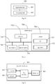
- Fig.11 is a schematic structural diagram of a terminal device according to an embodiment of the present disclosure.
- a terminal device 800 includes: at least one processor 810, a memory 820, at least one network interface 830, and a user interface 840.
- the various components in the terminal device 800 are coupled together by a bus system 850.
- the bus system 850 is configured to implement connection and communication among these components.
- the bus system 850 further includes a power bus, a control bus, and a status signal bus in addition to a data bus.
- various buses in Fig.11 are all labeled as the bus system 850.
- the user interface 840 may include a display, a keyboard or a point-and-click device (for example, a mouse), a trackball, a touch pad, a touch screen, or the like.
- the memory 820 in embodiments of the present disclosure may be a volatile memory or a nonvolatile memory, or may include both a volatile memory and a nonvolatile memory.
- the nonvolatile memory may be a read-only memory (Read-Only Memory, ROM), a programmable ROM (Programmable ROM, PROM), an erasable PROM (Erasable PROM, EPROM), an electrically EPROM (Electrically EPROM, EEPROM) or a flash memory.
- the volatile memory may be a random access memory (Random Access Memory, RAM), which is used as an external cache.
- RAMs such as a static RAM (Static RAM, SRAM), a dynamic RAM (Dynamic RAM, DRAM), a synchronous DRAM (Synchronous DRAM, SDRAM), a double-data-rate SDRAM (Double Data Rate SDRAM, DDRSDRAM), an enhanced SDRAM (Enhanced SDRAM, ESDRAM), a synchlink DRAM (Synchlink DRAM, SLDRAM), and a direct Rambus RAM (Direct Rambus RAM, DRRAM) may be used.
- the memory 820 in the system and method described in embodiments of the present disclosure is intended to include, but is not limited to, these and any other appropriate types of memories.
- the memory 820 stores executable modules or data structures, or a subset thereof, or an extended set thereof, for example, an operating system (Operating System, OS) 821 and an application 822.
- OS Operating System
- the operating system 821 includes various system programs, such as a framework layer program, a core library layer program, and a driver layer program, to implement various basic services and process a hardware-based task.
- the application 822 includes various applications such as a media player or a browser, to implement various application services.
- a program for implementing the method provided in embodiments of the present disclosure may be included in the application 822.
- the terminal device 800 further includes a computer program stored in the memory 820 and configured to be executed by the processor 810.
- the processor 810 is configured to execute the computer program to implement various processes of the foregoing methods for configuring a data flow, and may achieve the same technical effects. To avoid repetition, a detailed description is omitted herein.
- the foregoing methods disclosed in embodiments of the present disclosure may be applied to the processor 810 or implemented by the processor 810.
- the processor 810 may be an integrated circuit chip having a signal processing capability. During implementation, the steps in the foregoing methods may be accomplished by hardware integrated logic circuits or instructions in a software form in the processor 810.
- the processor 810 may be a general-purpose processor, a digital signal processor (Digital Signal Processor, DSP), an application specific integrated circuit (Application Specific Integrated Circuit, ASIC), a field programmable gate array (Field Programmable Gate Array, FPGA) or other programmable logic device, discrete gate or transistor logic device, a discrete hardware component, that can implement or execute the methods, steps, and logic block diagrams disclosed in some embodiments of the present disclosure.
- DSP Digital Signal Processor
- ASIC Application Specific Integrated Circuit
- FPGA Field Programmable Gate Array
- the general-purpose processor may be a microprocessor or the processor may be any conventional processor or the like.
- the steps of the methods for configuring a data flow disclosed with reference to the embodiments of the present disclosure may be directly performed and accomplished by a hardware decoding processor, or performed and accomplished by a combination of hardware and software modules in a decoding processor.
- the software modules may reside in a computer-readable storage medium well-established in the art, such as a RAM, a flash memory, a ROM, a PROM or an electrically erasable programmable memory or a register.
- a computer-readable storage medium is located in the memory 820.
- the processor 810 reads information from the memory 820 and accomplishes the steps in the foregoing methods using hardware of the processor 810.
- a computer program is stored in the computer-readable storage medium.
- the computer program is configured to be executed by the processor 810 to implement the steps in the method embodiments of the foregoing methods for configuring a data flow.
- a processing unit may be implemented in one or more ASICs, a DSP, a DSP device (DSP Device, DSPD), a programmable logic device (Programmable Logic Device, PLD), an FPGA, a general-purpose processor, a controller, a microcontroller, a microprocessor, other electronic unit configured to perform the functions in the present disclosure or a combination thereof.
- the techniques described in embodiments of the present disclosure may be implemented by modules (for example, processes or functions) performing the functions described in embodiments of the present disclosure.
- Software codes may be stored in a memory and executed by a processor.
- the memory may be implemented internal or external to a processor.
- Fig. 12 is a schematic structural diagram of a network side device according to another embodiment of the present disclosure.
- a network side device 900 includes: a processor 910, a transceiver 920, a memory 930, and a bus interface.
- the network side device 900 further includes a computer program stored in the memory 930 and executable by the processor 910, where the processor 910 is configured to execute the computer program to implement various processes of the foregoing methods for configuring a data flow, and may achieve the same technical effects. To avoid repetition, a detailed description is omitted herein.
- a bus architecture may include any quantity of interconnected buses and bridges, and connects various circuits including one or more processors represented by the processor 910 and memory represented by the memory 930.
- the bus architecture may also connect various other circuits such as peripherals, voltage regulators and power management circuits, which is well known in the art. Therefore, a further description thereof is omitted herein.
- a bus interface provides an interface.
- the transceiver 920 may be multiple elements, such as a transmitter and a receiver, to allow for communication with various other apparatuses on the transmission medium.
- the processor 910 is responsible for supervising the bus architecture and normal operation, and the memory 930 may store the data being used by the processor 910 during operation.
- An embodiment of the present disclosure further provides a computer readable storage medium storing therein a computer program, where the computer program is configured to be executed by a processor to implement various processes of the foregoing methods for configuring a data flow, and may achieve the same technical effects. To avoid repetition, a detailed description thereof is omitted herein.
- the computer readable storage medium includes a read-only memory (Read-Only Memory, ROM), a random access memory (Random Access Memory, RAM), a magnetic disk, an optic disc or the like.
- the system, device, module or unit set forth in the foregoing embodiments may specifically implemented by a computer chip or entity, or implemented by a product have a certain function.
- Atypical implementation device is a computer.
- the computer may be, for example: a personal computer, a laptop computer, a cellular phone, a camera phone, a smart phone, a personal digital assistant, a media player, a navigation device, an email device, a game console, a tablet computer, a wearable device, or any combination thereof.
- the computer readable storage medium includes permanent and non-permanent, removable and non-removable media, and may achieve information storage by any means or techniques.
- Information may be computer readable instruction, data structure, program module or other data.
- Computer storage medium may, for example, include, but is not limited to: phase change random access memory (Phase Change Random Access Memory, PRAM), static random access memory (Static Random Access Memory, SRAM), dynamic random access memory (Dynamic Random Access Memory, DRAM), other types of RAMs, ROM, EEPROM, flash memory or other memory technologies, compact disc read-only memory (Compact Disc Read-Only Memory, CD-ROM), digital versatile disc (Digital Versatile Disc, DVD) or other optical storages, cassette tape, magnetic tape, magnetic disk or other magnetic storage device or any other non-transmitting medium, which is configured to store information accessible by a computing device.
- the computer readable medium does not include transitory media, such as modulated data signals and carriers.
Landscapes
- Engineering & Computer Science (AREA)
- Computer Networks & Wireless Communication (AREA)
- Signal Processing (AREA)
- Computer Security & Cryptography (AREA)
- Mobile Radio Communication Systems (AREA)
Abstract
Description
- The present application claims a priority to the Chinese patent application No.
201810284187.0 - The present disclosure relates to the field of communications, in particular to a method and a device for configuring a data flow.
- A network side quality-of-service (Quality-of-Service, QoS) indication mechanism has been introduced in 5th-generation (5th-Generation, 5G) mobile communication systems, therefore QoS indication information (e.g., QoS flow identifier (Identifier, ID)) for IP data flow of user equipment (User Equipment, UE) needs to be added for both uplink and downlink data transmission. The protocol layer is located above the packet data convergence protocol (Packet Data Convergence Protocol, PDCP) layer. As shown in
Fig. 1 , one service data adaptation protocol (Service Data Adaptation Protocol, SDAP) entity corresponds to one higher-layer protocol data unit (Protocol Data Unit, PDU) session, and one SDAP entity may transmit data flows to a plurality of different data radio bearers (Data Radio Bearers, DRBs) which correspond to a plurality of PDCP entities as shown inFig.1 . - A network side is capable of re-configuring (for example, when a handover occurs) a DRB of a receiving end or transmitting end for a data flow (e.g., QoS data flow 1) of a terminal device, that is, the network side changes the DRB of the receiving end or transmitting end from a DRB1 (i.e., source DRB) to a DRB2 (i.e., target DRB).
- However, after the DRB corresponding to the receiving end or transmitting end of the SDAP entity is changed from the source DRB to the target DRB, since data flows in different DRBs arrive at the receiving end in a sequence, how to ensure that the received data flows are delivered to a higher-layer protocol entity according to a sequence in which the data flows arrive at the receiving end remains a problem.
- An object of embodiments of the present disclosure is to provide a method and a device for configuring a data flow, so as to solve the problem in the related art that how to ensure that the received data flows are delivered to a higher-layer protocol entity according to a sequence in which the data flows arrive at the receiving end.
- To solve the above technical problem, the following embodiments of the present disclosure are provided.
- In a first aspect, a method for configuring a data flow is provided. The method is operable by an SDAP entity transmitting end and includes:
transmitting indication information to an SDAP entity receiving end if a DRB corresponding to a QoS data flow is changed from a source DRB to a target DRB, wherein the indication information is configured to indicate that transmission of a first QoS data flow is completed on the source DRB or transmission of data of a second QoS data flow starts on the target DRB, and data of the QoS data flow includes data of the first QoS data flow and data of the second QoS data flow. - In a second aspect, a method for configuring a data flow is provided. The method is operable by an SDAP entity receiving end and includes:
receiving indication information from an SDAP entity transmitting end if a DRB corresponding to a QoS data flow is changed from a source DRB to a target DRB, wherein the indication information is configured to indicate that transmission of data of the QoS data flow is completed on the source DRB or transmission of data of the QoS data flow starts on the target DRB. - In a third aspect, a method for configuring a data flow is provided. The method is operable by an SDAP entity receiving end and includes:
- if a DRB corresponding to a QoS data flow is changed from a source DRB to a target DRB and data of the QoS data flow includes data of a first QoS data flow and data of a second QoS data flow, receiving the data of the first QoS data flow through the source DRB, and receiving the data of the second QoS data flow through the target DRB;
- performing data processing on the data of the QoS data flow based on a preset data processing rule;
- wherein the preset data processing rule at least includes:
- not transmitting the data of the QoS data flow to other protocol layer entity;
- not transmitting the data of the second QoS data flow to other protocol layer entity, and sequentially transmitting the data of the first QoS data flow to the other protocol layer entity according to a receiving sequence of the data of the first QoS data flow;
- storing the data of the first QoS data flow and the data of the second QoS data flow.
- In a fourth aspect, a device for configuring a data flow is provided. The device includes:
a transmission unit configured to transmit indication information to an SDAP entity receiving end if a DRB corresponding to a QoS data flow is changed from a source DRB to a target DRB, wherein the indication information is configured to indicate that transmission of a first QoS data flow is completed on the source DRB or transmission of data of a second QoS data flow starts on the target DRB, and data of the QoS data flow includes data of the first QoS data flow and data of the second QoS data flow. - In a fifth aspect, a device for configuring a data flow is provided. The device includes:
a reception unit configured to receive indication information from an SDAP entity transmitting end if a DRB corresponding to a QoS data flow is changed from a source DRB to a target DRB, wherein the indication information is configured to indicate that transmission of data of the QoS data flow is completed on the source DRB or transmission of data of the QoS data flow starts on the target DRB. - In a sixth aspect, a device for configuring a data flow is provided. The device includes:
- a reception unit configured to, if a DRB corresponding to a QoS data flow is changed from a source DRB to a target DRB and data of the QoS data flow includes data of a first QoS data flow and data of a second QoS data flow, receive the data of the first QoS data flow through the source DRB, and receive the data of the second QoS data flow through the target DRB;
- a processing unit configured to perform data processing on the data of the QoS data flow based on a preset data processing rule;
- wherein the preset data processing rule at least includes:
- not transmitting the data of the QoS data flow to other protocol layer entity;
- not transmitting the data of the second QoS data flow to other protocol layer entity, and sequentially transmitting the data of the first QoS data flow to the other protocol layer entity according to a receiving sequence of the data of the first QoS data flow;
- storing the data of the first QoS data flow and the data of the second QoS data flow.
- It can be seen from the foregoing technical solutions provided in the embodiments of the present disclosure that the solutions of the embodiments of the present disclosure have at least one of the following technical effects.
- In embodiments of the present disclosure, the SDAP entity transmitting end may transmit indication information to the SDAP entity receiving end if a DRB corresponding to a QoS data flow is changed from a source DRB to a target DRB, the indication information can be configured to indicate that transmission of a first data flow is completed on the source DRB or transmission of data of a second QoS data flow starts on the target DRB, such that after receiving the indication information, the SDAP entity receiving end may distinguish and process the QoS data flow received through the source DRB and the QoS data flow received through the target DRB differently, thereby ensuring that the SDAP entity receiving end sequentially delivers the received QoS data flows to a higher-layer protocol entity according to a sequence in which the QoS data flows arrive at the receiving end.
- In embodiments of the present disclosure, the SDAP entity receiving end may receive indication information from the SDAP entity transmitting end if a DRB corresponding to a QoS data flow is changed from a source DRB to a target DRB, the indication information can be configured to indicate that transmission of the first data flow is completed on the source DRB or transmission of the second QoS data flow starts on the target DRB, such that after receiving the indication information, the SDAP entity receiving end may distinguish and process the QoS data flow received through the source DRB and the QoS data flow received through the target DRB differently, thereby ensuring that the SDAP entity receiving end sequentially delivers the received QoS data flows to a higher-layer protocol entity according to a sequence in which the QoS data flows arrive at the receiving end.
- In embodiments of the present disclosure, the SDAP entity receiving end may receive the first QoS data flow through the source DRB and receive the second QoS data flow through the target DRB when a DRB corresponding to a QoS data flow is changed from a source DRB to a target DRB, and then perform data processing on the QoS data flow based on a preset data processing rule, so as to distinguish and process the first QoS data flow and the second QoS data flow differently, thereby ensuring that the SDAP entity receiving end sequentially delivers the received QoS data flows to a higher-layer protocol entity according to a sequence in which the QoS data flows arrive at the receiving end.
- To better clarify technical solutions of embodiments of the present application or in the related art, drawings used in description of the embodiments or the related art are briefly introduced hereinafter. Apparently, the described drawings merely illustrate some of the embodiments set forth in the present application. A person of ordinary skill in the art can obtain other drawings based on the described drawings without any creative efforts.
-
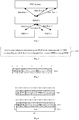
Fig.1 is a schematic diagram of transmission of data flows in the related art; -
Fig.2 is a schematic flow diagram of an implementation process of a method for configuring a data flow according to an embodiment of the present disclosure; -
Fig.3 is a schematic diagram of a data format used in the transmission of indication information according to an embodiment of the present disclosure; -
Fig.4 is another schematic diagram of a data format used in the transmission of indication information according to an embodiment of the present disclosure; -
Fig.5 is still another schematic diagram of a data format used in the transmission of indication information according to an embodiment of the present disclosure; -
Fig.6 is another schematic flow diagram of an implementation process of a method for configuring a data flow according to an embodiment of the present disclosure; -
Fig.7 is still another schematic flow diagram of an implementation process of a method for configuring a data flow according to an embodiment of the present disclosure; -
Fig.8 is a schematic structural diagram of a device for configuring a data flow according to an embodiment of the present disclosure; -
Fig.9 is another schematic structural diagram of a device for configuring a data flow according to an embodiment of the present disclosure; -
Fig.10 is still another schematic structural diagram of a device for configuring a data flow according to an embodiment of the present disclosure; -
Fig.11 is a schematic structural diagram of a terminal device according to an embodiment of the present disclosure; -
Fig.12 is a schematic structural diagram of a network side device according to an embodiment of the present disclosure. - To enable a better understanding of the technical solutions in the present application for those skilled in the art, the technical solutions in embodiments of the present disclosure are described clearly and completely in conjunction with drawings in the embodiments of the present disclosure. Apparently, the described embodiments are merely a part of rather than all the embodiments of the present application. All other embodiments obtained by a person ordinary skilled in the art based on the embodiments of the present application without any creative efforts fall within the scope of the present application.
- The technical solutions of the present application may be applied to various communication systems, such as global system of mobile communication (Global System of Mobile communication, GSM), code division multiple access (Code Division Multiple Access, CDMA) system, wideband code division multiple access (Wideband Code Division Multiple Access, WCDMA), general packet radio service (General Packet Radio Service, GPRS), long term evolution (Long Term Evolution, LTE)/long term evolution advanced (Long Term Evolution Advanced, LTE-A), and new radio (New Radio, NR).
- User equipment (User Equipment, UE), also called mobile terminal, mobile user equipment, etc., may communicate with one or more core networks via a radio access network (Radio Access Network, RAN). The UE may be a mobile terminal, e.g., a mobile phone (or cellular phone) or a computer provided with a mobile terminal, such as a portable, pocket-sized, handheld, computer built-in or in-vehicle mobile apparatus, which exchanges voice and/or data with the RAN.
- Abase station may be a base transceiver station (Base Transceiver Station, BTS) in GSM or CDMA, or may be a NodeB in WCDMA, or may be an evolutional Node B (eNB or eNodeB) in LTE or a 5G base station (gNB), which is not limited in the present application. However, for ease of description, a gNB is used as an example in description of following embodiments.
- As described in the background section, in the related art, when the DRB corresponding to a QoS data flow varies, e.g., the DRB is changed from a DRB1 (i.e., source DRB) to a DRB2 (i.e., target DRB), since data transmitted through different DRBs arrive at the receiving end in different sequences, and a solution as to how to ensure that, after data transmitted through the different DRBs arrive at the receiving end, the receiving end delivers (namely, transmits) the data transmitted through different DRBs to other protocol layer entity, namely, a higher-layer protocol entity (e.g., an Internet protocol (Internet Protocol, IP) layer), according to a sequence in which the data transmitted through the different DRBs arrive at the receiving end is still needed, it is necessary to propose a method for configuring a data flow on the basis of the related art, to ensure that, in the case that the DRB corresponding to a QoS data flow varies, after data transmitted through different DRBs arrive at the receiving end, the data transmitted through the different DRBs can still be sequentially delivered to a higher-layer protocol entity according to a sequence in which the data transmitted through the different DRBs arrive at the receiving end.
- To solve this problem, specific configuration information for an SDAP entity may be pre-configured by a network side or specified in a protocol in embodiments of the present disclosure. The specific configuration information may include one of or any combination of: 1) indication information carrying an SDAP header; 2) whether indication information is transmitted; 3) a quantity of time the indication information is transmitted.
-
Fig.2 is a schematic diagram of an implementation process of a method for configuring a data flow according to an embodiment of the present disclosure. The method inFig.2 is performed by an SDAP entity transmitting end. The method includes a step 101: transmitting indication information to an SDAP entity receiving end if a DRB corresponding to a QoS data flow is changed from a source DRB to a target DRB. - The indication information is used to indicate that transmission of a first QoS data flow is completed on the source DRB or transmission of data of a second QoS data flow starts on the target DRB, and data of the QoS data flow includes data of the first QoS data flow and data of the second QoS data flow.
- Optionally, the indication information is in one of following formats:
format 1, an SDAP header without carrying a data portion;format 2, an SDAP header including at least one reserved indication bit;format 3, an SDAP header including at least one reserved indication bit, and the SDAP header including at least one reserved indication bit being a control packet; where the reserved indication bit is used to indicate the indication information. - When the format of the indication information is
format 1, namely, an SDAP header without carrying a data portion, if the SDAP entity receiving end receives an SDAP packet transmitted by the SDAP entity transmitting end, and the SDAP packet is an SDAP header without carrying a data portion, it is indicated that the SDAP entity receiving end receives the indication information.Fig.3 is a schematic diagram of an indication information format which is an SDAP header without carrying a data portion according to an embodiment of the present disclosure.Fig.3 is a schematic diagram of one octet (abbreviated as Oct) of data. The Oct1 includes 8 bits, where the first two bits (shown as R) are reserved bits with a value of 0, and the remaining 6 bits (shown as QFI) are used to indicate a QoS data flow ID. - When the format of the indication information is
format 2, namely, an SDAP header including at least one reserved indication bit, if the SDAP entity receiving end receives an SDAP packet transmitted by the SDAP entity transmitting end, and the SDAP packet is an SDAP header including at least one reserved indication bit, it is indicated that the SDAP entity receiving end receives the indication information.Fig.4 is a schematic diagram of an indication information format which isformat 2 according to an embodiment of the present disclosure.Fig.4(a) is a schematic diagram of one Oct of data, where the first bit (shown as R) is a reserved bit with a value of 0, the second bit (shown as E) is a reserved indication bit with a value of 1, and the remaining 6 bits (shown as QFI) are used to indicate a QoS data flow ID.Fig.4(b) is a schematic diagram of two Octs of data, where 8 bits in the Oct1 are the same as that inFig.4(a) and Oct2 is carried data portion (shown as Data). In other words, when the format of the indication information isformat 2, the SDAP packet may not carry a data portion or may carry a data portion. - When the format of the indication information is
format 3, namely, an SDAP header including at least one reserved indication bit, and the SDAP header including at least one reserved indication bit being a control packet, if the SDAP entity receiving end receives an SDAP packet transmitted by the SDAP entity transmitting end, and the SDAP packet is an SDAP header including at least one reserved indication bit, and the SDAP header including at least one reserved indication bit being a control packet, it is indicated that the SDAP entity receiving end receives the indication information.Fig. 5 is a schematic diagram of an indication information format which isformat 3 according to an embodiment of the present disclosure.Fig.5 is a schematic diagram of one Oct of data, where the first bit (shown as C/D) is a bit used to indicate whether the SDAP packet is a data packet or a control packet, where a value of the first bit being 0 indicates that the SDAP packet is a data packet and a value of the first bit being 1 indicates that the SDAP packet is a control packet; the second bit (shown as E) is a reserved indication bit with a value of 1, and the remaining 6 bits (shown as QFI) are used to indicate a QoS data flow ID. In other words, when the format of the indication information isformat 3, the indication information is valid only when the conditions that the bit C/D has a value of 1, that is, the packet is a control packet, and the reserved indication bit E has a value of 1 are satisfied simultaneously. - It is understood, since the RLC entity for the source DRB or the target DRB has three operation modes: acknowledged mode (Acknowledged Mode, AM), unacknowledged mode (Unacknowledged Mode) and transparent mode (Transparent Mode), in order to ensure the reliability of data transmission, an embodiment of the present disclosure provides an solution, that is, a quantity of times the indication information is transmitted may be determined based on the operation mode of the radio link control (Radio Link Control, RLC) entity for the DRB used for transmitting the indication information; where the DRB used for transmitting the indication information is the source DRB or the target DRB.
- The quantity of times the indication information is transmitted may be determined based on the operation mode of the RLC entity for the DRB. In specific, if the operation mode of the RLC entity for the DRB used for transmitting the indication information is AM, since the AM mode itself can ensure the reliability of data transmission, it may be determined that the quantity of times the indication information is transmitted is 1. If the operation mode of the RLC entity for the DRB is UM or TM, since these two operation modes cannot ensure the reliability of data transmission by themselves, it may be determined that the quantity of times the indication information is transmitted is N, where N is a positive integer greater than 1. In other words, in these two operation modes, indication information may be repetitively transmitted multiple times to the SDAP entity receiving end, to ensure that the indication information can be received by the SDAP entity receiving end.
- The N may have the following values: N is equal to a preset quantity of times of transmission; N is less than the preset quantity of times of transmission; N is less than or equal to the preset quantity of times of transmission; N is greater than the preset quantity of times of transmission; N is greater than or equal to the preset quantity of times of transmission; here, the preset quantity of times of transmission is configured by a protocol or pre-configured by a network side device.
- Optionally, since the change of DRB corresponding to the QoS data flow from the source DRB to the target DRB usually occurs at the moment when the terminal device is handed over, the process tends to be relatively short. To avoid cumbersome operation and implementation, the transmitting the indication information to the SDAP entity receiving end may specifically include transmitting the indication information to the SDAP entity receiving end M times, where M is a positive integer greater than or equal to 1. Here, in the case that M is a positive integer greater than 1, regardless of whether the operation mode of the RLC entity for DRB is AM, UM or TM, the indication information may be repetitively transmitted to the SDAP entity receiving end multiple times (M times) to ensure the reliability of data transmission.
- The M may have the following values: M is equal to a preset quantity of times of transmission; M is less than the preset quantity of times of transmission; M is less than or equal to the preset quantity of times of transmission; M is greater than the preset quantity of times of transmission; M is greater than or equal to the preset quantity of times of transmission; here, the preset quantity of times of transmission is configured by a protocol or pre-configured by a network side device.
- Optionally, the transmitting the indication information to the SDAP entity receiving end may be triggered under the following two conditions:
condition 1, data of QoS data flow is not stored;condition 2, data of QoS data flow is stored, and after last data of the QoS data flow is transmitted to the source DRB. In order words, if thecondition 1 is met, that is, if data of QoS data flow is not stored, the indication information is transmitted to the SDAP entity receiving end; if thecondition 2 is met, that is, if data of QoS data flow is stored, after last data of the QoS data flow is transmitted to the source DRB, the indication information is transmitted to the SDAP entity receiving end. - It is understood, in embodiments of the present disclosure, data of the second QoS data flow may further be transmitted through the target DRB. In specific, the transmitting the data of the second QoS data flow through the target DRB includes the following two cases:
case 1, if transmission of the indication information starts, transmitting the data of the second QoS data flow through the target DRB;case 2, if transmission of the indication information is completed, transmitting the data of the second QoS data flow through the target DRB. Further, the data of the second QoS data flow may be transmitted through the target DRB immediately when it is determined that the DRB corresponding to the QoS data flow is changed from the source DRB to the target DRB. - Optionally, in embodiments of the present disclosure, the transmitting the indication information to the SDAP entity receiving end may specifically include: transmitting the indication information to the SDAP entity receiving end through the source DRB, or transmitting the indication information to the SDAP entity receiving end through the target DRB.
- In embodiments of the present disclosure, the SDAP entity transmitting end may transmit indication information to the SDAP entity receiving end when a DRB corresponding to a QoS data flow is changed from a source DRB to a target DRB, the indication information can be used to indicate that transmission of a first data flow is completed on the source DRB or transmission of data of a second QoS data flow starts on the target DRB, such that after receiving the indication information, the SDAP entity receiving end may distinguish and process the QoS data flow received through the source DRB and the QoS data flow received through the target DRB differently, thereby ensuring that the SDAP entity receiving end sequentially delivers the received QoS data flows to a higher-layer protocol entity according to a sequence in which the QoS data flows arrive at the receiving end.
-
Fig.6 is another schematic diagram of an implementation process of a method for configuring a data flow according to an embodiment of the present disclosure. The method inFig.6 is performed by an SDAP entity receiving end. The method includes a step 201: receiving indication information from an SDAP entity transmitting end if a DRB corresponding to a QoS data flow is changed from a source DRB to a target DRB, where the indication information is used to indicate that transmission of data of the QoS data flow is completed on the source DRB or transmission of data of the QoS data flow starts on the target DRB. - Optionally, in this case, the data of the QoS data flow may further be received, then the data of the QoS data flow is transmitted to other protocol layer entity. Since a DRB corresponding to a QoS data flow is changed from a source DRB to a target DRB, the following situation will result: a part of the QoS data flow is received through the source DRB and the other part is received through the target DRB. For ease of description, the two parts of data may be referred to as a first QoS data flow and a second QoS data flow. Thus, a QoS data flow includes the first QoS data flow and the second QoS data flow.
- Therefore, receiving the data of the QoS data flow includes: receiving data of the first QoS data flow through the source DRB; and receiving data of the second QoS data flow through the target DRB.
- Optionally, the transmitting the data of the QoS data flow to other protocol layer entity may specifically include: firstly, sequentially transmitting the data of the first QoS data flow to other protocol layer entity according to a receiving sequence of the data of the first QoS data flow; then, sequentially transmitting the data of the second QoS data flow to other protocol layer entity according to a receiving sequence of the data of the second QoS data flow. In other words, the data received earlier (i.e., data of the first QoS data flow that is received through the source DRB) is delivered to other protocol layer entity in the first place.
- Optionally, the receiving the indication information from the SDAP entity transmitting end may include: receiving the indication information from the SDAP entity transmitting end through the source DRB, or receiving the indication information through the target DRB.
- Since it is further needed to deliver data of the QoS data flow to other protocol layer after the data of the QoS data flow is received, data of the first QoS data flow and data of the second QoS data flow may further be stored. In order to easily distinguish the receiving sequence of data of the first QoS data flow and the second QoS data flow, and ensure that, in delivering these data to other protocol layer entity (e.g., a higher-layer protocol entity IP layer), these data are sequentially delivered according to the receiving sequence of these data, in embodiments of the present disclosure, storing the first QoS data flow and the second QoS data flow may specifically include: storing the data of the first QoS data flow and the data of the second QoS data flow according to a receiving sequence of the data of the first QoS data flow and the second QoS data flow.
- Since the first QoS data flow and the second QoS data flow are received through the source DRB and the target DRB respectively, data of the first QoS data flow is preceding to the data of the second QoS data flow in terms of receiving sequence. In order to easily distinguish the two QoS data flows, the data flows may be stored in the following two manners: in a manner, the data of the first QoS data flow may be stored at a first storage position, and the data of the second QoS data flow may be stored at a second storage position; in the other manner, the data of the first QoS data flow and the data of the second QoS data flow may be stored at a target storage position (i.e., stored at the same position), and the data of the first QoS data flow is assigned with a label different from that assigned to the data of the second QoS data flow.
- In embodiments of the present disclosure, the SDAP entity receiving end may receive indication information from the SDAP entity transmitting end when a DRB corresponding to a QoS data flow is changed from a source DRB to a target DRB, the indication information can be used to indicate that transmission of the first data flow is completed on the source DRB or transmission of the second QoS data flow starts on the target DRB, such that after receiving the indication information, the SDAP entity receiving end may distinguish and process the QoS data flow received through the source DRB and the QoS data flow received through the target DRB differently, thereby ensuring that the SDAP entity receiving end sequentially delivers the received QoS data flows to a higher-layer protocol entity according to a sequence in which the QoS data flows arrive at the receiving end.
-
Fig.7 is still another schematic diagram of an implementation process of a method for configuring a data flow according to an embodiment of the present disclosure. The method inFig.7 is performed by an SDAP entity receiving end. The method includes: - a step 301: if a DRB corresponding to a QoS data flow is changed from a source DRB to a target DRB and data of the QoS data flow includes data of a first QoS data flow and data of a second QoS data flow, receiving the data of the first QoS data flow through the source DRB, and receiving the data of the second QoS data flow through the target DRB;
- a step 302: performing data processing on the data of the QoS data flow based on a preset data processing rule;
- where the preset data processing rule at least includes: not transmitting the data of the QoS data flow to other protocol layer entity; not transmitting the data of the second QoS data flow to other protocol layer entity, and sequentially transmitting the data of the first QoS data flow to the other protocol layer entity according to a receiving sequence of the data of the first QoS data flow; storing the data of the first QoS data flow and the data of the second QoS data flow.
- Optionally, in order to easily distinguish the receiving sequence of data of the first QoS data flow and the second QoS data flow, and ensure that, in delivering (namely, transmitting) these data to other protocol layer entity (e.g., a higher-layer protocol entity IP layer), these data are sequentially delivered according to the receiving sequence of these data, in embodiments of the present disclosure, storing the first QoS data flow and the second QoS data flow may specifically include: storing the data of the first QoS data flow and the data of the second QoS data flow according to a receiving sequence of the data of the first QoS data flow and the second QoS data flow.
- Since the first QoS data flow and the second QoS data flow are received through the source DRB and the target DRB respectively, data of the first QoS data flow is preceding to the data of the second QoS data flow in terms of receiving sequence. In order to easily distinguish the two QoS data flows, the data flows may be stored in the following two manners: in a manner, the data of the first QoS data flow may be stored at a first storage position, and the data of the second QoS data flow may be stored at a second storage position; in the other manner, the data of the first QoS data flow and the data of the second QoS data flow may be stored at a target storage position (i.e., stored at the same position), and the data of the first QoS data flow is assigned with a label different from that assigned to the data of the second QoS data flow.
- In embodiments of the present disclosure, the SDAP entity receiving end may receive the first QoS data flow through the source DRB and receive the second QoS data flow through the target DRB when a DRB corresponding to a QoS data flow is changed from a source DRB to a target DRB, and then perform data processing on the QoS data flow based on a preset data processing rule, so as to distinguish and process the first QoS data flow and the second QoS data flow differently, thereby ensuring that the SDAP entity receiving end sequentially delivers the received QoS data flows to a higher-layer protocol entity according to a sequence in which the QoS data flows arrive at the receiving end.
-
Fig.8 is a schematic structural diagram of adevice 400 for configuring a data flow according to an embodiment of the present disclosure. As shown inFig.7 , thedevice 400 for configuring a data flow may include atransmission unit 401. - The
transmission unit 401 is configured to transmit indication information to an SDAP entity receiving end if a DRB corresponding to a QoS data flow is changed from a source DRB to a target DRB, where the indication information is used to indicate that transmission of a first QoS data flow is completed on the source DRB or transmission of data of a second QoS data flow starts on the target DRB, and data of the QoS data flow includes data of the first QoS data flow and data of the second QoS data flow. - Optionally, the indication information is in one of following formats:
- an SDAP header without carrying a data portion;
- an SDAP header including at least one reserved indication bit;
- an SDAP header including at least one reserved indication bit, and the SDAP header including at least one reserved indication bit being a control packet;
- where the reserved indication bit is used to indicate the indication information.
- Optionally, the device further includes:
- a determination unit 402 configured to determine, based on an operation mode of an RLC entity for a DRB used for transmitting the indication information, a quantity of times the indication information is transmitted;
- where the DRB used for transmitting the indication information is the source DRB or the target DRB.
- Optionally, the determination unit 402 is configured to:
- determine that the quantity of times the indication information is transmitted is 1, if the operation mode of the RLC entity for the DRB used for transmitting the indication information is an acknowledged mode AM;
- determine that the quantity of times the indication information is transmitted is N, if the operation mode of the RLC entity for the DRB is an unacknowledged mode UM or a transparent mode TM, where the N is a positive integer greater than 1.
- Optionally, the N is equal to a preset quantity of times of transmission; the N is less than the preset quantity of times of transmission; the N is less than or equal to the preset quantity of times of transmission; the N is greater than the preset quantity of times of transmission; the N is greater than or equal to the preset quantity of times of transmission; where the preset quantity of times of transmission is configured by a protocol or pre-configured by a network side.
- Optionally, the
transmission unit 401 is configured to:
transmit the indication information to the SDAP entity receiving end M times, where the M is a positive integer greater than or equal to 1. - Optionally, the M is equal to a preset quantity of times of transmission; the M is less than the preset quantity of times of transmission; the M is less than or equal to the preset quantity of times of transmission; the M is greater than the preset quantity of times of transmission; the M is greater than or equal to the preset quantity of times of transmission; where the preset quantity of times of transmission is configured by a protocol or pre-configured by a network side.
- Optionally, the
transmission unit 401 is configured to: - if data of the QoS data flow is not stored, transmit the indication information to the SDAP entity receiving end;
- if data of the QoS data flow is stored, transmit the indication information to the SDAP entity receiving end after last data of the QoS data flow is transmitted to the source DRB.
- Optionally, the device further includes:
a first transmission unit 403 configured to transmit data of the second QoS data flow through the target DRB. - The
device 400 for configuring a data flow may also implement the method inFig.2 . For a specific implementation, a reference may be made to the embodiment as shown inFig.2 . -
Fig.9 is another schematic structural diagram of adevice 500 for configuring a data flow according to an embodiment of the present disclosure. As shown inFig.9 , thedevice 500 for configuring a data flow may include areception unit 501. - The
reception unit 501 is configured to receive indication information from an SDAP entity transmitting end if a DRB corresponding to a QoS data flow is changed from a source DRB to a target DRB, where the indication information is used to indicate that transmission of data of the QoS data flow is completed on the source DRB or transmission of data of the QoS data flow starts on the target DRB. - Optionally, the device further includes:
- a first reception unit 502 configured to receive the data of the QoS data flow;
- a transmission unit 503 configured to transmit the data of the QoS data flow to other protocol layer entity.
- Optionally, the QoS data flow includes a first QoS data flow and a second QoS data flow,
where the first reception unit 502 is configured to: - receive data of the first QoS data flow through the source DRB; and,
- receive data of the second QoS data flow through the target DRB.
- Optionally, the transmission unit 503 is configured to:
- sequentially transmit the data of the first QoS data flow to other protocol layer entity according to a receiving sequence of the data of the first QoS data flow;
- after sequentially transmitting the data of the first QoS data flow to the other protocol layer entity according to the receiving sequence of the data of the first QoS data flow, sequentially transmit the data of the second QoS data flow to other protocol layer entity according to a receiving sequence of the data of the second QoS data flow.
- Optionally, the
reception unit 501 is configured to:
receive the indication information through the source DRB or target DRB. - Optionally, the device further includes:
a storage unit 504 configured to store the data of the first QoS data flow and the data of the second QoS data flow. - Optionally, the storage unit 504 is configured to:
store the data of the first QoS data flow and the data of the second QoS data flow according to a receiving sequence of the data of the first QoS data flow and the second QoS data flow. - Optionally, the storage unit 504 is configured to:
- store the data of the first QoS data flow at a first storage position, and store the data of the second QoS data flow at a second storage position ;
or, - store the data of the first QoS data flow and the data of the second QoS data flow at a target storage position, and assign a label to the data of the first QoS data flow while assigning a different label to the data of the second QoS data flow.
- The
device 500 for configuring a data flow may also implement the method inFig.6 . For a specific implementation, a reference may be made to the embodiment as shown inFig.6 . -
Fig. 10 is still another schematic structural diagram of adevice 600 for configuring a data flow according to an embodiment of the present disclosure. As shown inFig. 10 , thedevice 600 for configuring a data flow may include areception unit 601 and aprocessing unit 602. - The
reception unit 601 is configured to, if a DRB corresponding to a QoS data flow is changed from a source DRB to a target DRB and data of the QoS data flow includes data of a first QoS data flow and data of a second QoS data flow, receive the data of the first QoS data flow through the source DRB, and receive the data of the second QoS data flow through the target DRB. - The
processing unit 602 is configured to perform data processing on the data of the QoS data flow based on a preset data processing rule.
where the preset data processing rule at least includes: - not transmitting the data of the QoS data flow to other protocol layer entity;
- not transmitting the data of the second QoS data flow to other protocol layer entity, and sequentially transmitting the data of the first QoS data flow to the other protocol layer entity according to a receiving sequence of the data of the first QoS data flow;
- storing the data of the first QoS data flow and the data of the second QoS data flow.
- Optionally, when storing the first QoS data flow and the second QoS data flow, the
processing unit 602 is configured to:
store the data of the first QoS data flow and the data of the second QoS data flow according to a receiving sequence of the data of the first QoS data flow and the second QoS data flow. - Optionally, the
processing unit 602 is configured to: - store the data of the first QoS data flow at a first storage position, and store the data of the second QoS data flow at a second storage position;
or, - store the data of the first QoS data flow and the data of the second QoS data flow at a target storage position, and assign a label to the data of the first QoS data flow while assigning a different label to the data of the second QoS data flow.
- The
device 600 for configuring a data flow may also implement the method inFig.7 . For a specific implementation, a reference may be made to the embodiment as shown inFig.7 . -
Fig.11 is a schematic structural diagram of a terminal device according to an embodiment of the present disclosure. As shown inFig. 11 , aterminal device 800 includes: at least oneprocessor 810, amemory 820, at least onenetwork interface 830, and a user interface 840. The various components in theterminal device 800 are coupled together by a bus system 850. It may be understood that the bus system 850 is configured to implement connection and communication among these components. The bus system 850 further includes a power bus, a control bus, and a status signal bus in addition to a data bus. However, for clarity of description, various buses inFig.11 are all labeled as the bus system 850. - The user interface 840 may include a display, a keyboard or a point-and-click device (for example, a mouse), a trackball, a touch pad, a touch screen, or the like.
- It may be understood that the
memory 820 in embodiments of the present disclosure may be a volatile memory or a nonvolatile memory, or may include both a volatile memory and a nonvolatile memory. The nonvolatile memory may be a read-only memory (Read-Only Memory, ROM), a programmable ROM (Programmable ROM, PROM), an erasable PROM (Erasable PROM, EPROM), an electrically EPROM (Electrically EPROM, EEPROM) or a flash memory. The volatile memory may be a random access memory (Random Access Memory, RAM), which is used as an external cache. By way of example rather than limitation, many forms of RAMs such as a static RAM (Static RAM, SRAM), a dynamic RAM (Dynamic RAM, DRAM), a synchronous DRAM (Synchronous DRAM, SDRAM), a double-data-rate SDRAM (Double Data Rate SDRAM, DDRSDRAM), an enhanced SDRAM (Enhanced SDRAM, ESDRAM), a synchlink DRAM (Synchlink DRAM, SLDRAM), and a direct Rambus RAM (Direct Rambus RAM, DRRAM) may be used. Thememory 820 in the system and method described in embodiments of the present disclosure is intended to include, but is not limited to, these and any other appropriate types of memories. - In some implementations, the
memory 820 stores executable modules or data structures, or a subset thereof, or an extended set thereof, for example, an operating system (Operating System, OS) 821 and an application 822. - The operating system 821 includes various system programs, such as a framework layer program, a core library layer program, and a driver layer program, to implement various basic services and process a hardware-based task. The application 822 includes various applications such as a media player or a browser, to implement various application services. A program for implementing the method provided in embodiments of the present disclosure may be included in the application 822.
- In embodiments of the present disclosure, the
terminal device 800 further includes a computer program stored in thememory 820 and configured to be executed by theprocessor 810. Theprocessor 810 is configured to execute the computer program to implement various processes of the foregoing methods for configuring a data flow, and may achieve the same technical effects. To avoid repetition, a detailed description is omitted herein. - The foregoing methods disclosed in embodiments of the present disclosure may be applied to the
processor 810 or implemented by theprocessor 810. Theprocessor 810 may be an integrated circuit chip having a signal processing capability. During implementation, the steps in the foregoing methods may be accomplished by hardware integrated logic circuits or instructions in a software form in theprocessor 810. Theprocessor 810 may be a general-purpose processor, a digital signal processor (Digital Signal Processor, DSP), an application specific integrated circuit (Application Specific Integrated Circuit, ASIC), a field programmable gate array (Field Programmable Gate Array, FPGA) or other programmable logic device, discrete gate or transistor logic device, a discrete hardware component, that can implement or execute the methods, steps, and logic block diagrams disclosed in some embodiments of the present disclosure. The general-purpose processor may be a microprocessor or the processor may be any conventional processor or the like. The steps of the methods for configuring a data flow disclosed with reference to the embodiments of the present disclosure may be directly performed and accomplished by a hardware decoding processor, or performed and accomplished by a combination of hardware and software modules in a decoding processor. The software modules may reside in a computer-readable storage medium well-established in the art, such as a RAM, a flash memory, a ROM, a PROM or an electrically erasable programmable memory or a register. A computer-readable storage medium is located in thememory 820. Theprocessor 810 reads information from thememory 820 and accomplishes the steps in the foregoing methods using hardware of theprocessor 810. Specifically, a computer program is stored in the computer-readable storage medium. The computer program is configured to be executed by theprocessor 810 to implement the steps in the method embodiments of the foregoing methods for configuring a data flow. - It may be understood that these embodiments described in this disclosure may be implemented by hardware, software, firmware, middleware, microcode or a combination thereof. For hardware implementation, a processing unit may be implemented in one or more ASICs, a DSP, a DSP device (DSP Device, DSPD), a programmable logic device (Programmable Logic Device, PLD), an FPGA, a general-purpose processor, a controller, a microcontroller, a microprocessor, other electronic unit configured to perform the functions in the present disclosure or a combination thereof.
- For a software implementation, the techniques described in embodiments of the present disclosure may be implemented by modules (for example, processes or functions) performing the functions described in embodiments of the present disclosure. Software codes may be stored in a memory and executed by a processor. The memory may be implemented internal or external to a processor.
-
Fig. 12 is a schematic structural diagram of a network side device according to another embodiment of the present disclosure. As shown inFig. 12 , a network side device 900 includes: a processor 910, a transceiver 920, a memory 930, and a bus interface. - In an embodiment of the present disclosure, the network side device 900 further includes a computer program stored in the memory 930 and executable by the processor 910, where the processor 910 is configured to execute the computer program to implement various processes of the foregoing methods for configuring a data flow, and may achieve the same technical effects. To avoid repetition, a detailed description is omitted herein.
- In
Fig. 12 , a bus architecture may include any quantity of interconnected buses and bridges, and connects various circuits including one or more processors represented by the processor 910 and memory represented by the memory 930. The bus architecture may also connect various other circuits such as peripherals, voltage regulators and power management circuits, which is well known in the art. Therefore, a further description thereof is omitted herein. A bus interface provides an interface. The transceiver 920 may be multiple elements, such as a transmitter and a receiver, to allow for communication with various other apparatuses on the transmission medium. - The processor 910 is responsible for supervising the bus architecture and normal operation, and the memory 930 may store the data being used by the processor 910 during operation.
- An embodiment of the present disclosure further provides a computer readable storage medium storing therein a computer program, where the computer program is configured to be executed by a processor to implement various processes of the foregoing methods for configuring a data flow, and may achieve the same technical effects. To avoid repetition, a detailed description thereof is omitted herein. The computer readable storage medium includes a read-only memory (Read-Only Memory, ROM), a random access memory (Random Access Memory, RAM), a magnetic disk, an optic disc or the like.
- The above descriptions merely describe preferred embodiments of the present disclosure, but the scope of the present disclosure is not limited thereto. Any modifications, equivalent replacements or improvements made without departing from the spirit and principle of the disclosure shall fall within the scope of the present disclosure.
- The system, device, module or unit set forth in the foregoing embodiments may specifically implemented by a computer chip or entity, or implemented by a product have a certain function. Atypical implementation device is a computer. In specific, the computer may be, for example: a personal computer, a laptop computer, a cellular phone, a camera phone, a smart phone, a personal digital assistant, a media player, a navigation device, an email device, a game console, a tablet computer, a wearable device, or any combination thereof.
- The computer readable storage medium includes permanent and non-permanent, removable and non-removable media, and may achieve information storage by any means or techniques. Information may be computer readable instruction, data structure, program module or other data. Computer storage medium may, for example, include, but is not limited to: phase change random access memory (Phase Change Random Access Memory, PRAM), static random access memory (Static Random Access Memory, SRAM), dynamic random access memory (Dynamic Random Access Memory, DRAM), other types of RAMs, ROM, EEPROM, flash memory or other memory technologies, compact disc read-only memory (Compact Disc Read-Only Memory, CD-ROM), digital versatile disc (Digital Versatile Disc, DVD) or other optical storages, cassette tape, magnetic tape, magnetic disk or other magnetic storage device or any other non-transmitting medium, which is configured to store information accessible by a computing device. According to the definition herein, the computer readable medium does not include transitory media, such as modulated data signals and carriers.
- It is noted that terms "include," "have," and any variations thereof in the present disclosure are intended to cover a non-exclusive inclusion meaning, such that a process, a method, an article, or a device that includes a list of elements not only includes the list of elements, but also may include other elements not expressly listed or include elements inherent to the process, the method, the article, or the device. An element preceded by "includes or including" does not preclude existence of additional identical elements in the process, the method, the article, or the device including the element.
- The embodiments provided in the specification are described in a progressive manner, the same or similar part among various embodiments may be referred with each other, and the description of each embodiment focuses on its difference from other embodiments. Particularly, since system embodiments are basically similar to method embodiments, the descriptions of the system embodiments are relatively simple, for the relevant description, references may be made to the description of the method embodiments.
Claims (47)
- A method for configuring a data flow, operable by a service data adaptation protocol (SDAP) entity transmitting end, comprising:
transmitting indication information to an SDAP entity receiving end if a data radio bearer (DRB) corresponding to a quality of service (QoS) data flow is changed from a source DRB to a target DRB, wherein the indication information is configured to indicate that transmission of a first QoS data flow is completed on the source DRB or transmission of data of a second QoS data flow starts on the target DRB, and data of the QoS data flow comprises data of the first QoS data flow and data of the second QoS data flow. - The method according to claim 1, wherein the indication information is in one of following formats:an SDAP header without carrying a data portion;an SDAP header comprising at least one reserved indication bit;an SDAP header comprising at least one reserved indication bit, and the SDAP header comprising at least one reserved indication bit being a control packet; andwherein the reserved indication bit is used to indicate the indication information.
- The method according to claim 1, further comprising:determining, based on an operation mode of a radio link control (RLC) entity for a DRB used for transmitting the indication information, a quantity of times the indication information is transmitted;wherein the DRB used for transmitting the indication information is the source DRB or the target DRB.
- The method according to claim 3, wherein the determining, based on an operation mode of a radio link control (RLC) entity for a DRB used for transmitting the indication information, a quantity of times the indication information is transmitted, comprises:determining that the quantity of times the indication information is transmitted is 1, if the operation mode of the RLC entity for the DRB used for transmitting the indication information is an acknowledged mode (AM);determining that the quantity of times the indication information is transmitted is N, if the operation mode of the RLC entity for the DRB is an unacknowledged mode (UM) or a transparent mode (TM), wherein the N is a positive integer greater than 1.
- The method according to claim 4, wherein
the N is equal to a preset quantity of times of transmission;
the N is less than the preset quantity of times of transmission;
the N is less than or equal to the preset quantity of times of transmission;
the N is greater than the preset quantity of times of transmission;
the N is greater than or equal to the preset quantity of times of transmission;
wherein the preset quantity of times of transmission is configured by a protocol or pre-configured by a network device. - The method according to claim 1, wherein the transmitting the indication information to the SDAP entity receiving end, comprises:
transmitting the indication information to the SDAP entity receiving end for M times, wherein the M is a positive integer greater than or equal to 1. - The method according to claim 6, wherein
the M is equal to a preset quantity of times of transmission;
the M is less than the preset quantity of times of transmission;
the M is less than or equal to the preset quantity of times of transmission;
the M is greater than the preset quantity of times of transmission;
the M is greater than or equal to the preset quantity of times of transmission;
wherein the preset quantity of times of transmission is configured by a protocol or pre-configured by a network device. - The method according to claim 1, wherein the transmitting the indication information to the SDAP entity receiving end, comprises:if data of the QoS data flow is not stored, transmitting the indication information to the SDAP entity receiving end;if data of the QoS data flow is stored, transmitting the indication information to the SDAP entity receiving end after last data of the QoS data flow is transmitted to the source DRB.
- The method according to claim 1, further comprising:
transmitting data of the second QoS data flow through the target DRB. - The method according to claim 9, wherein the transmitting data of the second QoS data flow through the target DRB, comprises:if transmission of the indication information starts, transmitting the data of the second QoS data flow through the target DRB;if transmission of the indication information is completed, transmitting the data of the second QoS data flow through the target DRB.
- The method according to claim 1, wherein the transmitting the indication information to the SDAP entity receiving end, comprises:
transmitting the indication information to the SDAP entity receiving end through the source DRB or the target DRB. - A method for configuring a data flow, operable by a service data adaptation protocol (SDAP) entity receiving end, comprising:
receiving indication information from an SDAP entity transmitting end if a data radio bearer (DRB) corresponding to a quality of service (QoS) data flow is changed from a source DRB to a target DRB, wherein the indication information is configured to indicate that transmission of data of the QoS data flow is completed on the source DRB or transmission of data of the QoS data flow starts on the target DRB. - The method according to claim 12, further comprising:receiving the data of the QoS data flow;transmitting the data of the QoS data flow to other protocol layer entity.
- The method according to claim 13, wherein the QoS data flow comprises a first QoS data flow and a second QoS data flow;
the receiving the data of the QoS data flow comprises:receiving data of the first QoS data flow through the source DRB; and,receiving data of the second QoS data flow through the target DRB. - The method according to claim 14, wherein the transmitting the data of the QoS data flow to other protocol layer entity, comprises:sequentially transmitting the data of the first QoS data flow to other protocol layer entity according to a receiving sequence of the data of the first QoS data flow;after the sequentially transmitting the data of the first QoS data flow to the other protocol layer entity according to the receiving sequence of the data of the first QoS data flow, sequentially transmitting the data of the second QoS data flow to other protocol layer entity according to a receiving sequence of the data of the second QoS data flow.
- The method according to claim 12, wherein the receiving the indication information from the SDAP entity transmitting end, comprises:
receiving the indication information through the source DRB or target DRB. - The method according to claim 14, further comprising:
storing the data of the first QoS data flow and the data of the second QoS data flow. - The method according to claim 17, wherein the storing the data of the first QoS data flow and the data of the second QoS data flow, comprises:
storing the data of the first QoS data flow and the data of the second QoS data flow according to a receiving sequence of the data of the first QoS data flow and the second QoS data flow. - The method according to claim 17, wherein the storing the data of the first QoS data flow and the data of the second QoS data flow, comprises:storing the data of the first QoS data flow at a first storage position, and storing the data of the second QoS data flow at a second storage position;
or,storing the data of the first QoS data flow and the data of the second QoS data flow at a target storage position, and assigning a label to the data of the first QoS data flow while assigning a different label to the data of the second QoS data flow. - A method for configuring a data flow, operable by a service data adaptation protocol (SDAP) entity receiving end, comprising:if a data radio bearer (DRB) corresponding to a quality of service (QoS) data flow is changed from a source DRB to a target DRB and data of the QoS data flow comprises data of a first QoS data flow and data of a second QoS data flow, receiving the data of the first QoS data flow through the source DRB, and receiving the data of the second QoS data flow through the target DRB;performing data processing on the data of the QoS data flow based on a preset data processing rule;wherein the preset data processing rule at least comprises:not transmitting the data of the QoS data flow to other protocol layer entity;not transmitting the data of the second QoS data flow to other protocol layer entity, and sequentially transmitting the data of the first QoS data flow to the other protocol layer entity according to a receiving sequence of the data of the first QoS data flow;storing the data of the first QoS data flow and the data of the second QoS data flow.
- The method according to claim 20, wherein the storing the data the first QoS data flow and the data of the second QoS data flow, comprises:
storing the data of the first QoS data flow and the data of the second QoS data flow according to a receiving sequence of the data of the first QoS data flow and the second QoS data flow. - The method according to claim 21, wherein the storing the data of the first QoS data flow and the data of the second QoS data flow, comprises:storing the data of the first QoS data flow at a first storage position, and storing the data of the second QoS data flow at a second storage position;
or,storing the data of the first QoS data flow and the data of the second QoS data flow at a target storage position, and assigning a label to the data of the first QoS data flow while assigning a different label to the data of the second QoS data flow. - A device for configuring a data flow, comprising:
a transmission unit configured to transmit indication information to a service data adaptation protocol (SDAP) entity receiving end if a data radio bearer (DRB) corresponding to a quality of service (QoS) data flow is changed from a source DRB to a target DRB, wherein the indication information is configured to indicate that transmission of a first QoS data flow is completed on the source DRB or transmission of data of a second QoS data flow starts on the target DRB, and data of the QoS data flow comprises data of the first QoS data flow and data of the second QoS data flow. - The device according to claim 23, wherein the indication information is in one of following formats:an SDAP header without carrying a data portion;an SDAP header comprising at least one reserved indication bit;an SDAP header comprising at least one reserved indication bit, and the SDAP header comprising at least one reserved indication bit being a control packet;wherein the reserved indication bit is configured to indicate the indication information.
- The device according to claim 23, further comprising:a determination unit configured to determine, based on an operation mode of a radio link control (RLC) entity for a DRB used for transmitting the indication information, a quantity of times the indication information is transmitted;wherein the DRB used for transmitting the indication information is the source DRB or the target DRB.
- The device according to claim 25, wherein the determination unit is configured to:determine that the quantity of times the indication information is transmitted is 1, if the operation mode of the RLC entity for the DRB used for transmitting the indication information is an acknowledged mode (AM);determine that the quantity of times the indication information is transmitted is N, if the operation mode of the RLC entity for the DRB used for transmitting the indication information is an unacknowledged mode (UM) or a transparent mode (TM), wherein the N is a positive integer greater than 1.
- The device according to claim 26, wherein
the N is equal to a preset quantity of times of transmission;
the N is less than the preset quantity of times of transmission;
the N is less than or equal to the preset quantity of times of transmission;
the N is greater than the preset quantity of times of transmission;
the N is greater than or equal to the preset quantity of times of transmission;
wherein the preset quantity of times of transmission is configured by a protocol or pre-configured by a network device. - The device according to claim 23, wherein the transmission unit is configured to:
transmit the indication information to the SDAP entity receiving end for M times, wherein the M is a positive integer greater than or equal to 1. - The device according to claim 28, wherein
the M is equal to a preset quantity of times of transmission;
the M is less than the preset quantity of times of transmission;
the M is less than or equal to the preset quantity of times of transmission;
the M is greater than the preset quantity of times of transmission;
the M is greater than or equal to the preset quantity of times of transmission;
wherein the preset quantity of times of transmission is configured by a protocol or pre-configured by a network device. - The device according to claim 23, wherein the transmission unit is configured to:if data of the QoS data flow is not stored, transmit the indication information to the SDAP entity receiving end;if data of the QoS data flow is stored, transmit the indication information to the SDAP entity receiving end after last data of the QoS data flow is transmitted to the source DRB.
- The device according to claim 23, further comprising:
a first transmission unit configured to transmit data of the second QoS data flow through the target DRB. - The device according to claim 31, wherein the first transmission unit is configured to:if transmission of the indication information starts, transmit the data of the second QoS data flow through the target DRB;if transmission of the indication information is completed, transmit the data of the second QoS data flow through the target DRB.
- The device according to claim 23, wherein the transmission unit is configured to:
transmit the indication information to the SDAP entity receiving end through the source DRB or the target DRB. - A device for configuring a data flow, comprising:
a reception unit configured to receive indication information from a service data adaptation protocol (SDAP) entity transmitting end if a data radio bearer (DRB) corresponding to a quality of service (QoS) data flow is changed from a source DRB to a target DRB, wherein the indication information is configured to indicate that transmission of data of the QoS data flow is completed on the source DRB or transmission of data of the QoS data flow starts on the target DRB. - The device according to claim 34, further comprising:a first reception unit configured to receive the data of the QoS data flow;a transmission unit configured to transmit the data of the QoS data flow to other protocol layer entity.
- The device according to claim 35, wherein the QoS data flow comprises a first QoS data flow and a second QoS data flow,
the first reception unit is configured to:receive data of the first QoS data flow through the source DRB; and,receive data of the second QoS data flow through the target DRB. - The device according to claim 36, wherein the transmission unit is configured to:sequentially transmit the data of the first QoS data flow to other protocol layer entity according to a receiving sequence of the data of the first QoS data flow;after sequentially transmitting the data of the first QoS data flow to the other protocol layer entity according to the receiving sequence of the data of the first QoS data flow, sequentially transmit the data of the second QoS data flow to other protocol layer entity according to a receiving sequence of the data of the second QoS data flow.
- The device according to claim 34, wherein the reception unit is configured to:
receive the indication information through the source DRB or target DRB. - The device according to claim 36, further comprising:
a storage unit configured to store the data of the first QoS data flow and the data of the second QoS data flow. - The device according to claim 39, wherein the storage unit is configured to:
store the data of the first QoS data flow and the data of the second QoS data flow according to a receiving sequence of the data of the first QoS data flow and the second QoS data flow. - The device according to claim 39, wherein the storage unit is configured to:store the data of the first QoS data flow at a first storage position, and store the data of the second QoS data flow at a second storage position;
or,store the data of the first QoS data flow and the data of the second QoS data flow at a target storage position, and assign a label to the data of the first QoS data flow while assigning a different label to the data of the second QoS data flow. - A device for configuring a data flow, comprising:a reception unit configured to, if a data radio bearer (DRB) corresponding to a quality of service (QoS) data flow is changed from a source DRB to a target DRB and data of the QoS data flow comprises data of a first QoS data flow and data of a second QoS data flow, receive the data of the first QoS data flow through the source DRB, and receive the data of the second QoS data flow through the target DRB;a processing unit configured to perform data processing on the data of the QoS data flow based on a preset data processing rule;wherein the preset data processing rule at least comprises:not transmitting the data of the QoS data flow to other protocol layer entity;not transmitting the data of the second QoS data flow to other protocol layer entity, and sequentially transmitting the data of the first QoS data flow to the other protocol layer entity according to a receiving sequence of the data of the first QoS data flow;storing the data of the first QoS data flow and the data of the second QoS data flow.
- The device according to claim 42, wherein, when storing the first QoS data flow and the second QoS data flow, the processing unit is configured to:
store the data of the first QoS data flow and the data of the second QoS data flow according to a receiving sequence of the data of the first QoS data flow and the second QoS data flow. - The device according to claim 43, wherein the processing unit is configured to:store the data of the first QoS data flow at a first storage position, and store the data of the second QoS data flow at a second storage position;
or,store the data of the first QoS data flow and the data of the second QoS data flow at a target storage position, and assign a label to the data of the first QoS data flow while assigning a different label to the data of the second QoS data flow. - A terminal device, comprising a processor, a memory, a network interface and a user interface, wherein the memory stores therein a computer program configured to be executed by the processor, and the processor is configured to execute the computer program to implement steps of the method according to any one of claims 1 to 11.
- A network device, comprising a processor, a transceiver, a bus interface and a memory, wherein the memory stores therein a computer program configured to be executed by the processor, and the processor is configured to execute the computer program to implement steps of the method according to any one of claims 12 to 19 or steps of the method according to any one of claims 20 to 22.
- A computer readable storage medium storing therein a computer program, wherein the computer program is configured to be executed by a processor to implement steps of the method according to any one of claims 1 to 11, or steps of the method according to any one of claims 12 to 19, or steps of the method for configuring the data flow according to any one of claims 20 to 22.
Applications Claiming Priority (2)
| Application Number | Priority Date | Filing Date | Title |
|---|---|---|---|
| CN201810284187.0A CN110351221B (en) | 2018-04-02 | 2018-04-02 | Method and apparatus for configuring data flow |
| PCT/CN2019/080986 WO2019192464A1 (en) | 2018-04-02 | 2019-04-02 | Method and device for configuring data flow |
Publications (3)
| Publication Number | Publication Date |
|---|---|
| EP3780536A1 true EP3780536A1 (en) | 2021-02-17 |
| EP3780536A4 EP3780536A4 (en) | 2021-02-24 |
| EP3780536B1 EP3780536B1 (en) | 2026-03-04 |
Family
ID=68099839
Family Applications (1)
| Application Number | Title | Priority Date | Filing Date |
|---|---|---|---|
| EP19780541.9A Active EP3780536B1 (en) | 2018-04-02 | 2019-04-02 | Method and device for configuring data flow |
Country Status (7)
| Country | Link |
|---|---|
| US (2) | US11470508B2 (en) |
| EP (1) | EP3780536B1 (en) |
| JP (1) | JP7250036B2 (en) |
| KR (1) | KR102479690B1 (en) |
| CN (1) | CN110351221B (en) |
| ES (1) | ES3065838T3 (en) |
| WO (1) | WO2019192464A1 (en) |
Families Citing this family (2)
| Publication number | Priority date | Publication date | Assignee | Title |
|---|---|---|---|---|
| CN116490923B (en) * | 2020-12-07 | 2024-10-18 | Oppo广东移动通信有限公司 | Parameter setting method, device, equipment and storage medium |
| CN117082646A (en) * | 2022-05-09 | 2023-11-17 | 中国移动通信有限公司研究院 | SDAP function activation method, device and related equipment |
Family Cites Families (17)
| Publication number | Priority date | Publication date | Assignee | Title |
|---|---|---|---|---|
| WO2011100914A2 (en) * | 2011-04-12 | 2011-08-25 | 华为技术有限公司 | Long term evolution base station and method for processing data service thereof |
| CN105704197B (en) * | 2014-11-28 | 2020-04-10 | 电信科学技术研究院 | Data transmission method and system |
| US10582559B2 (en) * | 2015-11-05 | 2020-03-03 | Lg Electronics Inc. | Method for transmitting and receiving data in wireless communication system and apparatus supporting the same |
| US10959240B2 (en) | 2016-04-15 | 2021-03-23 | Qualcomm Incorporated | Providing quality-of-service in wireless communications |
| CN110995773B (en) * | 2016-05-24 | 2021-01-05 | 华为技术有限公司 | QoS control method and device |
| KR102499481B1 (en) | 2016-08-01 | 2023-02-14 | 삼성전자 주식회사 | Method and apparatus for managing data communication in wireless communication network |
| CN114885375B (en) * | 2016-08-09 | 2024-08-09 | 三星电子株式会社 | Method and apparatus for managing user plane operations in a wireless communication system |
| GB201621072D0 (en) * | 2016-12-12 | 2017-01-25 | Samsung Electronics Co Ltd | NR QOS handling |
| CN108809584B (en) * | 2017-05-05 | 2021-05-18 | 华为技术有限公司 | Data transmission method and communication device |
| CN108809596B (en) * | 2017-05-05 | 2023-07-21 | Oppo广东移动通信有限公司 | Communication method and device based on reverse service flow characteristics |
| JP7230827B2 (en) * | 2017-05-05 | 2023-03-01 | ソニーグループ株式会社 | Communication device, infrastructure equipment, wireless communication network and method |
| US20180324631A1 (en) | 2017-05-05 | 2018-11-08 | Mediatek Inc. | Using sdap headers for handling of as/nas reflective qos and to ensure in-sequence packet delivery during remapping in 5g communication systems |
| CN109246852B (en) * | 2017-06-13 | 2023-08-11 | 夏普株式会社 | Wireless protocol layer entity processing method and corresponding user equipment |
| CN109246766B (en) * | 2017-06-15 | 2023-05-30 | 夏普株式会社 | Wireless configuration method and corresponding user equipment |
| CN109151915B (en) * | 2017-06-16 | 2023-11-17 | 夏普株式会社 | Method, user equipment and base station for data packet delivery |
| EP3432633B1 (en) * | 2017-07-20 | 2019-10-02 | ASUSTek Computer Inc. | Method and apparatus for servicing qos (quality of service) flow in a wireless communication system |
| JP2020533820A (en) * | 2017-08-11 | 2020-11-19 | オッポ広東移動通信有限公司Guangdong Oppo Mobile Telecommunications Corp., Ltd. | Data transmission method, sender device and receiver device |
-
2018
- 2018-04-02 CN CN201810284187.0A patent/CN110351221B/en active Active
-
2019
- 2019-04-02 KR KR1020207029969A patent/KR102479690B1/en active Active
- 2019-04-02 JP JP2020553466A patent/JP7250036B2/en active Active
- 2019-04-02 WO PCT/CN2019/080986 patent/WO2019192464A1/en not_active Ceased
- 2019-04-02 ES ES19780541T patent/ES3065838T3/en active Active
- 2019-04-02 EP EP19780541.9A patent/EP3780536B1/en active Active
-
2020
- 2020-09-28 US US17/035,454 patent/US11470508B2/en active Active
-
2022
- 2022-08-23 US US17/893,793 patent/US11902835B2/en active Active
Also Published As
| Publication number | Publication date |
|---|---|
| US11902835B2 (en) | 2024-02-13 |
| US20210014735A1 (en) | 2021-01-14 |
| EP3780536B1 (en) | 2026-03-04 |
| WO2019192464A1 (en) | 2019-10-10 |
| ES3065838T3 (en) | 2026-05-08 |
| KR20200130735A (en) | 2020-11-19 |
| JP7250036B2 (en) | 2023-03-31 |
| CN110351221A (en) | 2019-10-18 |
| CN110351221B (en) | 2020-07-17 |
| EP3780536A4 (en) | 2021-02-24 |
| US11470508B2 (en) | 2022-10-11 |
| KR102479690B1 (en) | 2022-12-20 |
| JP2021520110A (en) | 2021-08-12 |
| US20220408314A1 (en) | 2022-12-22 |
Similar Documents
| Publication | Publication Date | Title |
|---|---|---|
| US11558843B2 (en) | Information transmission method and apparatus, and communication device | |
| US11089505B2 (en) | Method and device for transmitting data based on quality of service | |
| US12501429B2 (en) | Information transmission method and apparatus, and network device | |
| WO2020186529A1 (en) | Policy determining method and apparatus, and terminal | |
| US20210392612A1 (en) | Method, device and terminal for location message transmission processing | |
| EP3920491A1 (en) | Service processing method, device, chip, and computer program | |
| CN115086981B (en) | Information processing method, device and storage medium | |
| US11902835B2 (en) | Method and device for configuring data flow | |
| US20200187192A1 (en) | Method for indicating number of transmitting ports of ue, ue and network device | |
| US11265922B2 (en) | Method for accessing wireless local area network, terminal device, and network device | |
| EP3614714B1 (en) | Method for acquiring context configuration information, terminal device and access network device | |
| WO2021088007A1 (en) | Wireless communication method, terminal device, and network device | |
| US11588860B2 (en) | Flexible selection of security features in mobile networks | |
| US12501413B2 (en) | Methods and apparatuses for indicating a set of resources on a NR sidelink | |
| US11968728B2 (en) | Method of configuring service data adaptation protocol entity and device | |
| EP3713374A1 (en) | Method for accessing wireless local area network, terminal device, and network device | |
| CN113518461B (en) | Data transmission method and device | |
| US11343713B2 (en) | Data processing method, transmitter and receiver |
Legal Events
| Date | Code | Title | Description |
|---|---|---|---|
| STAA | Information on the status of an ep patent application or granted ep patent |
Free format text: STATUS: THE INTERNATIONAL PUBLICATION HAS BEEN MADE |
|
| PUAI | Public reference made under article 153(3) epc to a published international application that has entered the european phase |
Free format text: ORIGINAL CODE: 0009012 |
|
| STAA | Information on the status of an ep patent application or granted ep patent |
Free format text: STATUS: REQUEST FOR EXAMINATION WAS MADE |
|
| 17P | Request for examination filed |
Effective date: 20201019 |
|
| AK | Designated contracting states |
Kind code of ref document: A1 Designated state(s): AL AT BE BG CH CY CZ DE DK EE ES FI FR GB GR HR HU IE IS IT LI LT LU LV MC MK MT NL NO PL PT RO RS SE SI SK SM TR |
|
| AX | Request for extension of the european patent |
Extension state: BA ME |
|
| A4 | Supplementary search report drawn up and despatched |
Effective date: 20210126 |
|
| RIC1 | Information provided on ipc code assigned before grant |
Ipc: H04L 29/06 20060101AFI20210120BHEP Ipc: H04L 29/08 20060101ALI20210120BHEP |
|
| DAV | Request for validation of the european patent (deleted) | ||
| DAX | Request for extension of the european patent (deleted) | ||
| STAA | Information on the status of an ep patent application or granted ep patent |
Free format text: STATUS: EXAMINATION IS IN PROGRESS |
|
| 17Q | First examination report despatched |
Effective date: 20220330 |
|
| REG | Reference to a national code |
Ref country code: DE Free format text: PREVIOUS MAIN CLASS: H04L0029060000 Ipc: H04L0069322000 Ref country code: DE Ref legal event code: R079 Ref document number: 602019082097 Country of ref document: DE Free format text: PREVIOUS MAIN CLASS: H04L0029060000 Ipc: H04L0069322000 |
|
| RIC1 | Information provided on ipc code assigned before grant |
Ipc: H04W 28/02 20090101ALI20250328BHEP Ipc: H04L 69/22 20220101ALI20250328BHEP Ipc: H04L 69/322 20220101AFI20250328BHEP |
|
| GRAP | Despatch of communication of intention to grant a patent |
Free format text: ORIGINAL CODE: EPIDOSNIGR1 |
|
| STAA | Information on the status of an ep patent application or granted ep patent |
Free format text: STATUS: GRANT OF PATENT IS INTENDED |
|
| INTG | Intention to grant announced |
Effective date: 20250603 |
|
| GRAJ | Information related to disapproval of communication of intention to grant by the applicant or resumption of examination proceedings by the epo deleted |
Free format text: ORIGINAL CODE: EPIDOSDIGR1 |
|
| STAA | Information on the status of an ep patent application or granted ep patent |
Free format text: STATUS: EXAMINATION IS IN PROGRESS |
|
| GRAP | Despatch of communication of intention to grant a patent |
Free format text: ORIGINAL CODE: EPIDOSNIGR1 |
|
| STAA | Information on the status of an ep patent application or granted ep patent |
Free format text: STATUS: GRANT OF PATENT IS INTENDED |
|
| INTC | Intention to grant announced (deleted) | ||
| INTG | Intention to grant announced |
Effective date: 20251014 |
|
| GRAS | Grant fee paid |
Free format text: ORIGINAL CODE: EPIDOSNIGR3 |
|
| GRAA | (expected) grant |
Free format text: ORIGINAL CODE: 0009210 |
|
| STAA | Information on the status of an ep patent application or granted ep patent |
Free format text: STATUS: THE PATENT HAS BEEN GRANTED |
|
| AK | Designated contracting states |
Kind code of ref document: B1 Designated state(s): AL AT BE BG CH CY CZ DE DK EE ES FI FR GB GR HR HU IE IS IT LI LT LU LV MC MK MT NL NO PL PT RO RS SE SI SK SM TR |
|
| REG | Reference to a national code |
Ref country code: CH Ref legal event code: F10 Free format text: ST27 STATUS EVENT CODE: U-0-0-F10-F00 (AS PROVIDED BY THE NATIONAL OFFICE) Effective date: 20260304 Ref country code: GB Ref legal event code: FG4D |
|
| REG | Reference to a national code |
Ref country code: IE Ref legal event code: FG4D |
|
| REG | Reference to a national code |
Ref country code: DE Ref legal event code: R096 Ref document number: 602019082097 Country of ref document: DE |
|
| PGFP | Annual fee paid to national office [announced via postgrant information from national office to epo] |
Ref country code: GB Payment date: 20260311 Year of fee payment: 8 |
|
| REG | Reference to a national code |
Ref country code: NL Ref legal event code: FP |
|
| PGFP | Annual fee paid to national office [announced via postgrant information from national office to epo] |
Ref country code: NL Payment date: 20260317 Year of fee payment: 8 |
|
| PGFP | Annual fee paid to national office [announced via postgrant information from national office to epo] |
Ref country code: FR Payment date: 20260309 Year of fee payment: 8 |
|
| REG | Reference to a national code |
Ref country code: ES Ref legal event code: FG2A Ref document number: 3065838 Country of ref document: ES Kind code of ref document: T3 Effective date: 20260508 |