EP3780482A1 - Quantum key distribution method, device and storage medium - Google Patents
Quantum key distribution method, device and storage medium Download PDFInfo
- Publication number
- EP3780482A1 EP3780482A1 EP19786235.2A EP19786235A EP3780482A1 EP 3780482 A1 EP3780482 A1 EP 3780482A1 EP 19786235 A EP19786235 A EP 19786235A EP 3780482 A1 EP3780482 A1 EP 3780482A1
- Authority
- EP
- European Patent Office
- Prior art keywords
- node
- routing path
- quantum key
- target routing
- target
- Prior art date
- Legal status (The legal status is an assumption and is not a legal conclusion. Google has not performed a legal analysis and makes no representation as to the accuracy of the status listed.)
- Pending
Links
- 238000000034 method Methods 0.000 title claims abstract description 62
- 238000004422 calculation algorithm Methods 0.000 claims description 66
- 238000004891 communication Methods 0.000 claims description 42
- 238000010586 diagram Methods 0.000 description 33
- 230000006870 function Effects 0.000 description 27
- 230000015654 memory Effects 0.000 description 25
- 238000004364 calculation method Methods 0.000 description 14
- 238000012545 processing Methods 0.000 description 13
- 238000004590 computer program Methods 0.000 description 9
- 238000005516 engineering process Methods 0.000 description 5
- 230000003287 optical effect Effects 0.000 description 3
- 238000011161 development Methods 0.000 description 2
- 238000012986 modification Methods 0.000 description 2
- 230000004048 modification Effects 0.000 description 2
- 239000007787 solid Substances 0.000 description 2
- 230000001133 acceleration Effects 0.000 description 1
- 238000004458 analytical method Methods 0.000 description 1
- 230000005540 biological transmission Effects 0.000 description 1
- 238000006243 chemical reaction Methods 0.000 description 1
- 238000013500 data storage Methods 0.000 description 1
- 238000013461 design Methods 0.000 description 1
- 238000007726 management method Methods 0.000 description 1
- 239000013307 optical fiber Substances 0.000 description 1
- 230000008520 organization Effects 0.000 description 1
- 230000005610 quantum mechanics Effects 0.000 description 1
- 239000004065 semiconductor Substances 0.000 description 1
- VLCQZHSMCYCDJL-UHFFFAOYSA-N tribenuron methyl Chemical compound COC(=O)C1=CC=CC=C1S(=O)(=O)NC(=O)N(C)C1=NC(C)=NC(OC)=N1 VLCQZHSMCYCDJL-UHFFFAOYSA-N 0.000 description 1
Images


Classifications
-
- H—ELECTRICITY
- H04—ELECTRIC COMMUNICATION TECHNIQUE
- H04L—TRANSMISSION OF DIGITAL INFORMATION, e.g. TELEGRAPHIC COMMUNICATION
- H04L9/00—Cryptographic mechanisms or cryptographic arrangements for secret or secure communications; Network security protocols
- H04L9/08—Key distribution or management, e.g. generation, sharing or updating, of cryptographic keys or passwords
- H04L9/0816—Key establishment, i.e. cryptographic processes or cryptographic protocols whereby a shared secret becomes available to two or more parties, for subsequent use
- H04L9/0819—Key transport or distribution, i.e. key establishment techniques where one party creates or otherwise obtains a secret value, and securely transfers it to the other(s)
-
- H—ELECTRICITY
- H04—ELECTRIC COMMUNICATION TECHNIQUE
- H04L—TRANSMISSION OF DIGITAL INFORMATION, e.g. TELEGRAPHIC COMMUNICATION
- H04L63/00—Network architectures or network communication protocols for network security
- H04L63/06—Network architectures or network communication protocols for network security for supporting key management in a packet data network
-
- H—ELECTRICITY
- H04—ELECTRIC COMMUNICATION TECHNIQUE
- H04L—TRANSMISSION OF DIGITAL INFORMATION, e.g. TELEGRAPHIC COMMUNICATION
- H04L63/00—Network architectures or network communication protocols for network security
- H04L63/18—Network architectures or network communication protocols for network security using different networks or channels, e.g. using out of band channels
-
- H—ELECTRICITY
- H04—ELECTRIC COMMUNICATION TECHNIQUE
- H04L—TRANSMISSION OF DIGITAL INFORMATION, e.g. TELEGRAPHIC COMMUNICATION
- H04L9/00—Cryptographic mechanisms or cryptographic arrangements for secret or secure communications; Network security protocols
- H04L9/06—Cryptographic mechanisms or cryptographic arrangements for secret or secure communications; Network security protocols the encryption apparatus using shift registers or memories for block-wise or stream coding, e.g. DES systems or RC4; Hash functions; Pseudorandom sequence generators
- H04L9/0618—Block ciphers, i.e. encrypting groups of characters of a plain text message using fixed encryption transformation
-
- H—ELECTRICITY
- H04—ELECTRIC COMMUNICATION TECHNIQUE
- H04L—TRANSMISSION OF DIGITAL INFORMATION, e.g. TELEGRAPHIC COMMUNICATION
- H04L9/00—Cryptographic mechanisms or cryptographic arrangements for secret or secure communications; Network security protocols
- H04L9/08—Key distribution or management, e.g. generation, sharing or updating, of cryptographic keys or passwords
- H04L9/0816—Key establishment, i.e. cryptographic processes or cryptographic protocols whereby a shared secret becomes available to two or more parties, for subsequent use
- H04L9/0819—Key transport or distribution, i.e. key establishment techniques where one party creates or otherwise obtains a secret value, and securely transfers it to the other(s)
- H04L9/0822—Key transport or distribution, i.e. key establishment techniques where one party creates or otherwise obtains a secret value, and securely transfers it to the other(s) using key encryption key
-
- H—ELECTRICITY
- H04—ELECTRIC COMMUNICATION TECHNIQUE
- H04L—TRANSMISSION OF DIGITAL INFORMATION, e.g. TELEGRAPHIC COMMUNICATION
- H04L9/00—Cryptographic mechanisms or cryptographic arrangements for secret or secure communications; Network security protocols
- H04L9/08—Key distribution or management, e.g. generation, sharing or updating, of cryptographic keys or passwords
- H04L9/0816—Key establishment, i.e. cryptographic processes or cryptographic protocols whereby a shared secret becomes available to two or more parties, for subsequent use
- H04L9/0819—Key transport or distribution, i.e. key establishment techniques where one party creates or otherwise obtains a secret value, and securely transfers it to the other(s)
- H04L9/083—Key transport or distribution, i.e. key establishment techniques where one party creates or otherwise obtains a secret value, and securely transfers it to the other(s) involving central third party, e.g. key distribution center [KDC] or trusted third party [TTP]
-
- H—ELECTRICITY
- H04—ELECTRIC COMMUNICATION TECHNIQUE
- H04L—TRANSMISSION OF DIGITAL INFORMATION, e.g. TELEGRAPHIC COMMUNICATION
- H04L9/00—Cryptographic mechanisms or cryptographic arrangements for secret or secure communications; Network security protocols
- H04L9/08—Key distribution or management, e.g. generation, sharing or updating, of cryptographic keys or passwords
- H04L9/0816—Key establishment, i.e. cryptographic processes or cryptographic protocols whereby a shared secret becomes available to two or more parties, for subsequent use
- H04L9/0852—Quantum cryptography
-
- H—ELECTRICITY
- H04—ELECTRIC COMMUNICATION TECHNIQUE
- H04L—TRANSMISSION OF DIGITAL INFORMATION, e.g. TELEGRAPHIC COMMUNICATION
- H04L9/00—Cryptographic mechanisms or cryptographic arrangements for secret or secure communications; Network security protocols
- H04L9/08—Key distribution or management, e.g. generation, sharing or updating, of cryptographic keys or passwords
- H04L9/0816—Key establishment, i.e. cryptographic processes or cryptographic protocols whereby a shared secret becomes available to two or more parties, for subsequent use
- H04L9/0852—Quantum cryptography
- H04L9/0855—Quantum cryptography involving additional nodes, e.g. quantum relays, repeaters, intermediate nodes or remote nodes
-
- H—ELECTRICITY
- H04—ELECTRIC COMMUNICATION TECHNIQUE
- H04L—TRANSMISSION OF DIGITAL INFORMATION, e.g. TELEGRAPHIC COMMUNICATION
- H04L9/00—Cryptographic mechanisms or cryptographic arrangements for secret or secure communications; Network security protocols
- H04L9/08—Key distribution or management, e.g. generation, sharing or updating, of cryptographic keys or passwords
- H04L9/0861—Generation of secret information including derivation or calculation of cryptographic keys or passwords
- H04L9/0866—Generation of secret information including derivation or calculation of cryptographic keys or passwords involving user or device identifiers, e.g. serial number, physical or biometrical information, DNA, hand-signature or measurable physical characteristics
-
- H—ELECTRICITY
- H04—ELECTRIC COMMUNICATION TECHNIQUE
- H04L—TRANSMISSION OF DIGITAL INFORMATION, e.g. TELEGRAPHIC COMMUNICATION
- H04L9/00—Cryptographic mechanisms or cryptographic arrangements for secret or secure communications; Network security protocols
- H04L9/08—Key distribution or management, e.g. generation, sharing or updating, of cryptographic keys or passwords
- H04L9/0894—Escrow, recovery or storing of secret information, e.g. secret key escrow or cryptographic key storage
-
- H—ELECTRICITY
- H04—ELECTRIC COMMUNICATION TECHNIQUE
- H04L—TRANSMISSION OF DIGITAL INFORMATION, e.g. TELEGRAPHIC COMMUNICATION
- H04L9/00—Cryptographic mechanisms or cryptographic arrangements for secret or secure communications; Network security protocols
- H04L9/12—Transmitting and receiving encryption devices synchronised or initially set up in a particular manner
-
- H—ELECTRICITY
- H04—ELECTRIC COMMUNICATION TECHNIQUE
- H04L—TRANSMISSION OF DIGITAL INFORMATION, e.g. TELEGRAPHIC COMMUNICATION
- H04L9/00—Cryptographic mechanisms or cryptographic arrangements for secret or secure communications; Network security protocols
- H04L9/14—Cryptographic mechanisms or cryptographic arrangements for secret or secure communications; Network security protocols using a plurality of keys or algorithms
-
- H—ELECTRICITY
- H04—ELECTRIC COMMUNICATION TECHNIQUE
- H04L—TRANSMISSION OF DIGITAL INFORMATION, e.g. TELEGRAPHIC COMMUNICATION
- H04L2209/00—Additional information or applications relating to cryptographic mechanisms or cryptographic arrangements for secret or secure communication H04L9/00
- H04L2209/76—Proxy, i.e. using intermediary entity to perform cryptographic operations
Definitions
- This application relates to the quantum communication field, and in particular, to a quantum key distribution method and device, and a storage medium.
- Secure quantum communication is a combination of a quantum feature and conventional cryptography, and uses a basic principle and feature of quantum mechanics to ensure communication security. After more than 30 years of development, secure quantum communication is practical in the market currently.
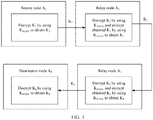
- FIG. 1 is a schematic diagram of a quantum key distribution method in the prior art.
- a routing path includes a source node A 1 , a relay node A 2 , a relay node A 3 , and a destination node A 4
- K 1 is a to-be-shared quantum key between the source node A 1 and the destination node A 4 and needs to be transmitted from the source node A 1 to the destination node A 4 .
- the source node A 1 encrypts K 1 by using K A1A2 , to obtain K 2 , and transmits obtained K 2 to the relay node A 2 , where K A1A2 is a private key to be shared between the source node A 1 and the relay node A 2 .
- the relay node A 2 decrypts K 2 by using K A1A2 , then encrypts K 1 by using K A2A3 , to obtain K 3 , and transmits obtained K 3 to the relay node A 3 , where K A2A3 is a private key to be shared between the relay node A 2 and the relay node A 3 .
- the relay node A 3 decrypts K 3 by using K A2A3 , then encrypts K 1 by using K A3A4 , to obtain K 4 , and transmits obtained K 4 to the destination node A 4 , where K A3A4 is a private key to be shared between the relay node A 3 and the destination node A 4 .
- the destination node A 4 decrypts K 4 by using K A3A4 , to obtain K 1 .
- the to-be-shared quantum key K 1 between the source node A 1 and the destination node A 4 is decrypted by each intermediate node, and consequently security is relatively low.
- Embodiments of this application provide a quantum key distribution method and device, and a storage medium, to resolve a prior-art problem of low security when a quantum key is distributed between nodes.
- an embodiment of this application provides a quantum key distribution method, where the method includes:
- a second quantum key corresponding to the (i-1) th node on the target routing path is the same as the first quantum key corresponding to the i th node on the target routing path, and the second quantum key corresponding to the i th node on the target routing path is the same as a first quantum key corresponding to the (i+1) th node on the target routing path.
- the second ciphertext corresponding to the source node on the target routing path is obtained by encrypting the to-be-shared quantum key between the source node on the target routing path and the target node on the target routing path by using the second quantum key corresponding to the source node on the target routing path.
- the second ciphertext that is sent by the (i-1) th node and that corresponds to the (i-1) th node is the first ciphertext received by the i th node from the (i-1) th node on the target routing path.
- the i th node sends the third quantum key corresponding to the i th node on the target routing path to the target node on the target routing path; or the i th node encrypts, by using the third quantum key corresponding to the i th node on the target routing path, the first ciphertext received from the (i-1) th node on the target routing path, and sends the obtained second ciphertext corresponding to the i th node to the (i+1) th node on the target routing path. It can be learned that the i th node does not decrypt the received first ciphertext. In other words, the to-be-shared quantum key between the source node and the target node on the target routing path is not obtained by a node through decryption. Therefore, quantum key distribution security is improved.
- N is an integer greater than 1
- a first quantum key corresponding to the i th node on the first routing path is different from a first quantum key corresponding to the i th node on the second routing path
- a second quantum key corresponding to the i th node on the first routing path is different from a second quantum key corresponding to the i th node on the second routing path. Therefore, for each routing path, a node distributes a corresponding quantum key to the routing path to implement a one time system, so that quantum key distribution security can be further improved.
- the method before the determining, by an i th node based on a first correspondence, a first quantum key corresponding to the i th node on a target routing path, the method further includes: receiving, by the i th node, indication information that is sent by a centralized controller or the (i-1) th node on the target routing path and that is used to indicate the first quantum key on the target routing path corresponding to the i th node on the target routing path in the first correspondence; or determining, by the i th node based on obtained network topology information of a quantum communication system and a first preset rule, the first quantum key on the target routing path corresponding to the i th node on the target routing path in the first correspondence. It can be learned that a first quantum key corresponding to a node on a routing path may be determined by using a plurality of solutions, so as to improve solution flexibility.
- the determining, by the i th node based on obtained network topology information of a quantum communication system and a first preset rule, the first quantum key on the target routing path corresponding to the i th node on the target routing path in the first correspondence includes: determining, by the i th node based on a ranking relationship between numbers of N (i-1) th nodes on the N routing paths passing through the i th node, a ranking relationship between numbers of N (i+1) th nodes on the N routing paths passing through the i th node, and a ranking relationship between numbers of the N routing paths passing through the i th node, a ranking of the N routing paths passing through the i th node, and determining, based on the ranking of the N routing paths, the first quantum key corresponding to the i th node on the target routing path; or determining, by the i th node based on a ranking relationship between numbers of N (i+1) th nodes on the N
- a plurality of routing paths passing through the i th node may be ranked in a plurality of manners, and then the first quantum key corresponding to the i th node on the target routing path is determined based on the ranking of the routing paths. Therefore, convenience and flexibility of determining a first quantum key corresponding to an i th node on a routing path can be improved.
- the method before the determining, by the i th node based on a second correspondence, a second quantum key corresponding to the i th node on the target routing path, the method further includes: receiving, by the i th node, indication information that is sent by the centralized controller or the (i+1) th node corresponding to the target routing path and that is used to indicate the second quantum key corresponding to the i th node on the target routing path in the second correspondence; or determining, by the i th node based on the obtained network topology information of the quantum communication system and a second preset rule, the second quantum key corresponding to the i th node on the target routing path in the second correspondence. It can be learned that a second quantum key corresponding to a node on a routing path may be determined by using a plurality of solutions, so as to improve solution flexibility.
- the i th node determines, based on a ranking relationship between numbers of W routing paths passing through the i th node and the (i+1) th node on the target routing path, a ranking of the W routing paths passing through the i th node and the (i+1) 111 node on the target routing path, and determines, based on the ranking of the W routing paths, the second quantum key corresponding to the i th node on the target routing path, where W is a positive integer that is not greater than N; or the i th node determines, based on a ranking relationship between numbers of W (i+2) th nodes on W routing paths passing through the i th node and the (i+1) 111 node on the target routing path, and a ranking relationship between numbers of the W routing paths passing through the i th node and the (i+1) 111 node on the target routing path, a ranking of the W routing paths passing through the i th node and the (i+1) 111 node on
- a plurality of routing paths passing through the i th node may be ranked in a plurality of manners, and then the second quantum key corresponding to the i th node on the target routing path is determined based on the ranking of the routing paths. Therefore, convenience and flexibility of determining a second quantum key corresponding to an i th node on a routing path can be improved.
- a first algorithm used when the i th node encrypts, by using the third quantum key corresponding to the i th node on the target routing path, the first ciphertext received from the (i-1) th node on the target routing path meets a formula (1) in subsequent specific embodiments. Therefore, after decrypting the received first ciphertext, the destination node can obtain the to-be-shared quantum key.
- an embodiment of this application provides a quantum key distribution device.
- the quantum key distribution device includes a memory, a transceiver, and a processor.
- the memory is configured to store an instruction.
- the processor is configured to: execute the instruction stored in the memory, and control the transceiver to receive a signal and send a signal.
- the quantum key distribution device is configured to perform the method in any one of the first aspect or the possible implementations of the first aspect.
- an embodiment of this application provides a quantum key distribution device, configured to implement the method in any one of the first aspect or the possible implementations of the first aspect.
- the quantum key distribution device includes corresponding functions separately configured to implement steps in the foregoing method.
- the functions may be implemented by hardware, or may be implemented by hardware executing corresponding software.
- the hardware or software includes one or more modules corresponding to the foregoing functions.
- a structure of the quantum key distribution device includes a processing unit and a transceiver unit. These units can execute corresponding functions in the foregoing method example. For details, refer to the detailed descriptions in the method example. Details are not described herein again.
- an embodiment of this application provides a computer storage medium.
- the computer storage medium stores an instruction.
- the instruction When the instruction is run on a computer, the computer is enabled to perform the method in any one of the first aspect or the possible implementations of the first aspect.
- an embodiment of this application provides a computer program product including an instruction.
- the computer program product When the computer program product is run on a computer, the computer is enabled to perform the method in any one of the first aspect or the possible implementations of the first aspect.
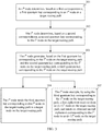
- FIG. 3 is an example of a schematic flowchart of a quantum key distribution method according to an embodiment of this application. As shown in FIG. 3 , the method provided in this embodiment of this application includes the following steps.
- the i th node is the i th node on the target routing path.
- the first quantum key corresponding to the i th node on the target routing path is a quantum key that is obtained by the i th node and that is to be shared between the i th node and an (i-1) th node on the target routing path.
- the first correspondence includes a correspondence between each of N routing paths passing through the i th node and each of N first quantum keys corresponding to the i th node, and the N routing paths are in a one-to-one correspondence with the N first quantum keys corresponding to the i th node, where N is a positive integer, and i is a positive integer.
- the target routing path is any one of the N routing paths. In this embodiment of this application, the target routing path is merely a name for ease of description, and does not constitute a limitation.
- Step 302 The i th node determines, based on a second correspondence, a second quantum key corresponding to the i th node on the target routing path.
- Step 303 The i th node generates, based on the first quantum key corresponding to the i th node on the target routing path and the second quantum key corresponding to the i th node on the target routing path, a third quantum key corresponding to the i th node on the target routing path.
- this embodiment of this application provides two optional implementations. In one optional implementations, step 304 is performed after step 303. In the other optional implementations, step 305 is performed after step 303. Whether step 304 or step 305 is performed after step 303 may be flexibly selected by a person skilled in the art based on an actual application scenario.
- Step 305 The i th node encrypts, by using the third quantum key corresponding to the i th node on the target routing path, a first ciphertext received from the (i-1) th node on the target routing path, and sends an obtained second ciphertext corresponding to the i th node to the (i+1) th node on the target routing path.
- the first ciphertext received by the i th node from the (i-1) th node on the target routing path is a second ciphertext that is sent by the (i-1) th node and that corresponds to the (i-1) th node.
- a 0 th node is a source node on the target routing path
- a second ciphertext corresponding to the source node on the target routing path is obtained by encrypting a to-be-shared quantum key between the source node on the target routing path and the target node on the target routing path by using a second quantum key corresponding to the source node on the target routing path.
- a second quantum key corresponding to the (i-1) th node on the target routing path is the same as the first quantum key corresponding to the i th node on the target routing path, and the second quantum key corresponding to the i th node on the target routing path is the same as a first quantum key corresponding to the (i+1) th node on the target routing path.
- an algorithm used when the i th node encrypts, by using the third quantum key corresponding to the i th node on the target routing path, the first ciphertext received from the (i-1) th node on the target routing path may be referred to as a first algorithm.
- an algorithm used when the third quantum key corresponding to the i th node on the target routing path is generated based on the first quantum key corresponding to the i th node on the target routing path and the second quantum key corresponding to the i th node on the target routing path may be referred to as a second algorithm.
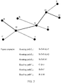
- FIG. 4 is an example of a schematic diagram of a quantum key distribution method performed for a routing path L 2 in FIG. 2 .
- a solution shown in FIG. 4 is used to perform a solution corresponding to step 305.
- a to-be-shared quantum key between the source node B and the destination node Q is K BQ (L 2 ), and the source node B needs to transmit the to-be-shared quantum key K BQ (L 2 ) to the destination node Q.
- K BQ K BQ
- the source node B encrypts, by using the second quantum key K BD (L 2 ) corresponding to the source node B, the to-be-shared quantum key K BQ (L 2 ) between the source node on the target routing path and the target node on the target routing path, to obtain a second ciphertext K B (L 2 ) corresponding to the source node B.
- the source node B sends the second ciphertext K B (L 2 ) corresponding to the source node to the relay node D.
- An algorithm used to encrypt K BQ (L 2 ) by using K BD (L 2 ) may be referred to as a third algorithm.
- the third algorithm may be the same as the first algorithm, or may be another algorithm.
- the relay node D receives a first ciphertext K B (L 2 ) from the source node B.
- the second ciphertext that is sent by the source node B and that corresponds to the source node B is the same as the first ciphertext received by the relay node D.
- a first ciphertext received by a relay node may also be referred to as the first ciphertext corresponding to the relay node.
- the first ciphertext K B (L 2 ) received by the relay node D may also be referred to as the first ciphertext K B (L 2 ) corresponding to the relay node D.
- the target routing path is the routing path L 2
- the node D is an i th node on the target routing path
- the node B is an (i-1) th node on the target routing path
- the node E is an (i+1) th node on the target routing path
- the node G is an (i+2) th node on the target routing path.
- the relay node D encrypts, by using the third quantum key K BE (L 2 ), the received first ciphertext K B (L 2 ) corresponding to the relay node D, to obtain a second ciphertext K D (L 2 ) corresponding to the relay node D.
- the relay node D sends the second ciphertext K D (L 2 ) corresponding to the relay node D to the relay node E.
- An algorithm used to encrypt the first ciphertext K B (L 2 ) by using the third quantum key K BE (L 2 ) to generate the second ciphertext K D (L 2 ) may be the first algorithm.
- the relay node E receives a first ciphertext K D (L 2 ) from the relay node D.
- the second ciphertext that is sent by the relay node D and that corresponds to the relay node D is the same as the first ciphertext received by the relay node E.
- the relay node E generates, based on a first quantum key K ED (L 2 ) corresponding to the relay node E on the routing path L 2 and a second quantum key K E G(L 2 ) corresponding to the relay node E on the routing path L 2 , a third quantum key K D G(L 2 ) corresponding to the relay node E on the routing path L 2 .
- the relay node E encrypts the first ciphertext K D (L 2 ) by using the third quantum key K D G(L 2 ), to obtain a second ciphertext K E (L 2 ) corresponding to the relay node E.
- the relay node E sends the second ciphertext K E (L 2 ) corresponding to the relay node E to the relay node G.
- the relay node G receives a first ciphertext K E (L 2 ) from the relay node E.
- the second ciphertext that is sent by the relay node E and that corresponds to the relay node E is the same as the first ciphertext received by the relay node G.
- the relay node G generates, based on a first quantum key KG E (L 2 ) corresponding to the relay node G on the routing path L 2 and a second quantum key KG Q (L 2 ) corresponding to the relay node G on the routing path L 2 , a third quantum key K EQ (L 2 ) corresponding to the relay node G on the routing path L 2 .
- the relay node G encrypts the first ciphertext K E (L 2 ) by using the third quantum key K EQ (L 2 ), to obtain a second ciphertext K G (L 2 ) corresponding to the relay node G.
- the relay node G sends the second ciphertext K G (L 2 ) corresponding to the relay node G to the relay node Q.
- the destination node Q receives a first ciphertext K G (L 2 ) from the relay node G, and K G (L 2 ) may be referred to as the first ciphertext corresponding to the destination node Q.
- the destination node Q decrypts the first ciphertext K G (L 2 ) by using a first quantum key K QG (L 2 ) corresponding to the destination node Q on the routing path L 2 , to obtain the to-be-shared quantum key K BQ (L 2 ).
- An algorithm used for decryption processing may be referred to as a fourth algorithm.
- the fourth algorithm may be the same as the first algorithm, or may be another algorithm.
- FIG. 5 is an example of a schematic diagram of another quantum key distribution method performed for a routing path L 2 L 2 in FIG. 2 .
- the solution shown in FIG. 4 is used to perform a solution corresponding to step 304.
- the source node may send generated K B (L 2 ) to the destination node Q by using a typical signal or through a quantum channel.
- Each relay node also sends a third quantum key correspondingly generated by each relay node to the destination node Q. For example, in FIG.
- a relay node does not decrypt information sent by a previous node of the relay node, so that a to-be-shared quantum key between a source node and a destination node is not obtained by a relay node through decryption, in other words, the relay node does not obtain the to-be-shared quantum key between the source node and the destination node through decryption. This can improve security of the to-be-shared quantum key between the source node and the destination node.
- a relay node does not encrypt and decrypt information sent by a previous node of the relay node, so that a time and a resource occupied for performing optical-to-electrical conversion on a to-be-shared quantum key on a routing path can be saved.
- step 303 an algorithm used when the third quantum key corresponding to the i th node on the target routing path is generated based on the first quantum key corresponding to the i th node on the target routing path and the second quantum key corresponding to the i th node on the target routing path is the second algorithm, and an algorithm used when the i th node encrypts, by using the third quantum key corresponding to the i th node on the target routing path, the first ciphertext received from the (i-1) th node on the target routing path is the first algorithm.
- L j is an identifier of the target routing path
- f E ( K DB ( L 2 ) , K DE ( L 2 )) means that an operation corresponding to the second algorithm is performed on the first quantum key K DB (L 2 ) corresponding to the relay node D on the routing path L 2 and the second quantum key K DE (L 2 ) corresponding to the relay node D on the routing path L 2 , and a calculation result of f E ( K DB ( L 2 ) , k DE ( L 2 )) is the third quantum key K BE (L 2 ), shown in FIG. 4 , corresponding to the relay node D on the routing path L 2 .
- f E ( K ED ( L 2 ) , K EG ( L 2 )) means that an operation corresponding to the second algorithm is performed on the first quantum key K ED (L 2 ) corresponding to the relay node E on the routing path L 2 and the second quantum key K EG (L 2 ) corresponding to the relay node E on the routing path L 2 , and a calculation result of f E ( K ED ( L 2 ) , K EG ( L 2 )) is the third quantum key K DG (L 2 ), shown in FIG. 4 , corresponding to the relay node E on the routing path L 2 .
- g ( f E ( K DB ( L 2 ) , K DE ( L 2 )), f E ( K ED ( L 2 ) , K EG ( L 2 ))) means that an operation corresponding to the first algorithm is performed on the third quantum key K BE (L 2 ) corresponding to the relay node D on the routing path L 2 and the third quantum key K DG (L 2 ) corresponding to the relay node E on the routing path L 2 , and when K DE (L 2 ) is the same as K ED (L 2 ), a result of g ( f E ( K DB ( L 2 ), K DE (L 2 )), f E ( K ED ( L 2 ), K EG ( L 2 ))) is f E (K DB ( L 2 ), K EG ( L 2 )).
- the destination node may obtain the to-be-shared quantum key.
- a person skilled in the art may learn that, in an actual operation, the destination node may not perform the detailed calculation shown in the foregoing formula (2), but performs, by using K QG (L 2 ), only the operation corresponding to the first algorithm on received K G (L 2 ).
- the first algorithm, the second algorithm, the third algorithm, and the fourth algorithm are all exclusive OR algorithms.
- the first algorithm, the second algorithm, the third algorithm, and the fourth algorithm are implemented in a plurality of manners. For example, two first algorithms correspondingly used by two nodes are two different algorithms, or two second algorithms correspondingly used by two nodes are two different algorithms.
- f E (•) may be a function set, may include a series of encryption functions ⁇ f E 0 , f E 1 ... ⁇ , and may further include a decryption function f D .
- f E 0 is the foregoing third algorithm used to encrypt a to-be-shared quantum key between the source node and the destination node
- f E 1 , f E 2 ... is a function used by each relay node to calculate a third quantum key and encrypt a received first ciphertext.
- the communications system applicable to this embodiment of this application may include a plurality of routing paths. If N is an integer greater than 1, for a first routing path and a second routing path in N routing paths passing through an i th node, a first quantum key corresponding to the i th node on the first routing path is different from a first quantum key corresponding to the i th node on the second routing path, and a second quantum key corresponding to the i th node on the first routing path is different from a second quantum key corresponding to the i th node on the second routing path.
- the first routing path and the second routing path are two different routing paths in the N routing paths. As shown in FIG.
- the first correspondence in step 301 and the second correspondence in step 302 may be obtained in a plurality of manners.
- the following describes several manners of obtaining the first quantum key corresponding to the i th node on the routing path in the first correspondence: an optional implementation a1, an optional implementation a2, and an optional implementation a3.
- indication information used to indicate the first quantum key corresponding to the i th node on the target routing path in the first correspondence is delivered by a centralized controller.
- the (i-1) th node on the routing path may obtain the second quantum key corresponding to the (i-1) th node on the target routing path through calculation, and then send the second quantum key to the i th node. Because the second quantum key corresponding to the (i-1) th node on the target routing path is the same as the first quantum key corresponding to the i th node on the target routing path, the i th node may learn of the first quantum key corresponding to the i th node on the target routing path in the first correspondence.
- each node (other than the target node) on the target routing path obtains a second quantum key corresponding to each node on the target routing path through calculation, and then sends the second quantum key corresponding to each node on the target routing path to a next node of each node on the target routing path. Because the second quantum key corresponding to each node on the target routing path is the same as a first quantum key corresponding to the next node of each node on the target routing path, the node on the target routing path may obtain, in the implementation a2, the first quantum key corresponding to the i th node on the routing path in the first correspondence.
- the i th node determines, based on a ranking relationship between numbers of a plurality of (i-1) th nodes on the N routing paths passing through the i th node, a ranking relationship between numbers of N (i+1) th nodes on a plurality of routing paths passing through the i th node, and a ranking relationship between numbers of the N routing paths passing through the i th node, a ranking of the plurality of routing paths passing through the i th node, and determines, based on the ranking of the plurality of routing paths, the first quantum key corresponding to the i th node on the target routing path.
- FIG. 6 is an example of a schematic diagram in which the node D in FIG. 2 generates, in the implementation a3-1, a first correspondence corresponding to the node D.
- each node has a global number.
- the global numbers of the nodes may be represented by Arabic numerals, letters, or some characters having a preset ranking relationship.
- FIG. 2 it is assumed that letters corresponding to the nodes are ranked in a letter ranking sequence in an alphabet. As shown in FIG.
- all paths on which the node D is used as a relay node are the routing path L 1 to the routing path L 5 , and previous-hop nodes of the node D on the five routing paths are first ranked.
- next-hop nodes of the node D on four routing paths on which the previous-hop node of the node D is the node B are ranked.
- the next-hop nodes of the node D are the node E and the node F, and a ranking result is shown in the second row to the fifth row in the third column in FIG. 6 .
- a next-hop node of the node C on one routing path on which the previous-hop node of the node D is the node C is ranked.
- the next-hop node of the node D is the node C
- the next-hop node of the node D is the node F
- a ranking result is shown in the sixth row in the third column in FIG. 6 .
- the plurality of routing paths may be ranked based on global numbers of the routing paths.
- each routing path may have a global number, and there may be a ranking relationship between the numbers of the routing paths. It is assumed that global numbers of the six routing paths in FIG. 2 are ranked from L 1 to L 6 . As shown in FIG.
- routing path L 1 , the routing path L 2 , and the routing path L 3 there are three routing paths passing through the node B, the node D, and the node E: the routing path L 1 , the routing path L 2 , and the routing path L 3 , and the routing path L 1 , the routing path L 2 , and the routing path L 3 are ranked in the second row to the fourth row in the fourth column based on a ranking relationship between global numbers of the routing path L 1 , the routing path L 2 , and the routing path L 3 .
- the node D has ranked all routing paths passing through the node D, and then may sequentially distribute quantum keys to the routing paths based on the ranking relationship.
- the second row and the third row in the fourth column in FIG. 6 are used as an example for description.
- a first quantum key distributed by the node D to the routing path L 1 is K DB (L 1 )
- a first quantum key distributed by the node D to the routing path L2 is K DB (L 2 ).
- a weight may be set for each routing path based on consumption of a quantum key on each routing path and/or service attribute information, to determine a quantity of quantum keys distributed to each routing path in each quantum key distribution period.
- K DB (L 1 ) is only an identifier corresponding to the first quantum key distributed by the node D to the routing path L 1 .
- K DB (L 1 ) may be an identifier corresponding to a 256-bit quantum key in each quantum key distribution period.
- K DB (L 1 ) may be identifiers corresponding to the three 256-bit quantum keys in each quantum key distribution period.
- routing paths are flexibly ranked.
- FIG. 6 only shows a possible implementation, and there may be another implementation.
- a plurality of (i+1) th nodes are first ranked based on a ranking relationship between numbers of the plurality of (i+1) th nodes on a plurality of routing paths passing through the i th node, then a plurality of (i-1) th nodes are ranked based on a ranking relationship between numbers of the plurality of (i-1) th nodes on the plurality of routing paths passing through the i th node, and finally the plurality of routing paths are ranked based on a ranking relationship between numbers of the plurality of routing paths passing through the i th node. Details are not described herein.
- FIG. 7 is an example of a schematic diagram in which the node D in FIG. 2 generates, in the implementation a3-2, a first quantum key corresponding to the node D on the routing path L 2 .
- a plurality of routing paths passing through the node D may be first determined: the routing path L 1 , the routing path L 2 , the routing path L 3 , the routing path L 4 , and the routing path L 5 .
- next-hop nodes of the node D on the routing path L 1 , the routing path L 2 , the routing path L 3 , the routing path L 4 , and the routing path L 5 may be ranked, where a ranking result is shown in the second row to the sixth row in the second column in FIG.
- next-hop nodes on the plurality of routing paths passing through the node D are the node E and the node F.
- the routing path L 1 , the routing path L 2 , the routing path L 3 , the routing path L 4 , and the routing path L 5 are ranked based on numbers of the routing paths, where a ranking result is shown in the second row to the sixth row in the third column in FIG. 7 .
- first quantum keys corresponding to the node D on all the routing paths are sequentially distributed to all the routing paths based on the ranking of the routing path L 1 , the routing path L 2 , the routing path L 3 , the routing path L 4 , and the routing path L 5 .
- the i th node determines, based on a ranking relationship between numbers of the N routing paths passing through the i th node, a ranking of the N routing paths passing through the i th node, and determines, based on the ranking of the N routing paths, the first quantum key corresponding to the i th node on the target routing path.
- FIG. 8 is an example of a schematic diagram in which the node D in FIG. 2 generates, in the implementation a3-3, a first quantum key corresponding to the node D on the routing path L 2 .
- a plurality of routing paths passing through the node D may be first determined: the routing path L 1 , the routing path L 2 , the routing path L 3 , the routing path L 4 , and the routing path L 5 .
- the routing path L 1 , the routing path L 2 , the routing path L 3 , the routing path L 4 , and the routing path L 5 are ranked based on numbers of the routing paths, where a ranking result is shown in the second row to the sixth row in the second column in FIG. 8 .
- corresponding first quantum keys are sequentially distributed to all the routing paths based on the ranking of the routing path L 1 , the routing path L 2 , the routing path L 3 , the routing path L 4 , and the routing path L 5 .
- indication information used to indicate the second quantum key corresponding to the i th node on the routing path in the second correspondence is delivered by the centralized controller.
- the indication information used to indicate the second quantum key corresponding to the i th node on the routing path in the second correspondence may be directly the second quantum key corresponding to the i th node on the target routing path, or may be other information that can indicate the correspondence.
- the i th node receives indication information that is sent by the centralized controller and that is used to indicate the first quantum key corresponding to the i th node on the target routing path.
- the centralized controller may collect service requests in an entire network, and may better calculate a routing path in the entire network. Subsequently, the centralized controller may calculate a second correspondence corresponding to each node when the node is used as a node, and then deliver the second correspondence to each node.
- indication information used to indicate the second quantum key corresponding to the i th node on the routing path in the second correspondence is sent by the (i+1) th node on the target routing path.
- the (i+1) th node corresponding to the routing path may obtain a first quantum key corresponding to the (i+1) th node on the target routing path through calculation, and then send the first quantum key to the i th node. Because the first quantum key corresponding to the (i+1) th node on the target routing path is the same as the second quantum key corresponding to the i th node on the target routing path, the i th node may learn of the second quantum key corresponding to the i th node on the target routing path in the second correspondence.
- each node (other than the source node) on the target routing path obtains a first quantum key corresponding to each node on the target routing path through calculation, and then sends the first quantum key corresponding to each node on the target routing path to a previous node of each node on the target routing path. Because the first quantum key corresponding to each node on the target routing path is the same as a second quantum key corresponding to the previous node of each node on the target routing path, the node on the target routing path may obtain, in the implementation b2, the second quantum key corresponding to the i th node on the routing path in the second correspondence.
- the i th node determines, based on the obtained network topology information of the quantum communication system and a second preset rule, the second quantum key corresponding to the i th node on the target routing path.
- the implementation b3 there may be a plurality of implementations in which the i th node determines, based on the obtained network topology information of the quantum communication system and the second preset rule, the second quantum key corresponding to the i th node on the target routing path.
- the following describes an optional implementation b3-1 and an optional implementation b3-2.
- the i th node determines, based on a ranking relationship between numbers of a plurality of (i+2) th nodes on a plurality of routing paths passing through the i th node and the (i+1) th node on the target routing path, and a ranking relationship between numbers of the plurality of routing paths passing through the i th node and the (i+1) th node on the target routing path, a ranking of the plurality of routing paths passing through the i th node and the (i+1) th node on the target routing path, and determines, based on the ranking of the plurality of routing paths, the second quantum key corresponding to the i th node on the target routing path.
- FIG. 9 is an example of a schematic diagram in which the node D in FIG. 2 generates, in the implementation b3-1, a second correspondence corresponding to the node D.
- FIG. 9 assuming that a quantum key to be shared between the node D and the node E needs to be determined, all routing paths passing through the node D and the node E need to be first determined.
- all the routing paths passing through the node D and the node E are the routing path L 1 , the routing path L 2 , and the routing path L 3 .
- next-hop nodes of the node E on the routing path L 1 , the routing path L 2 , and the routing path L 3 may be ranked, and a ranking result is shown in the second row to the fourth row in the second column in FIG. 6 .
- a plurality of routing paths on which the next-hop node of the node E is the node G are ranked based on numbers of the plurality of routing paths, and a ranking result is shown in the second row to the third row in the third column in FIG. 9 .
- routing path L 1 There is only one routing path on which the next-hop of the node E is the node H, and the routing path may be ranked in the fourth row in the third column in FIG. 9 .
- second quantum keys corresponding to the node D on all the routing paths are sequentially distributed to all the routing paths based on the ranking of the routing path L 1 , the routing path L 2 , and the routing path L 3 .
- FIG. 10 is an example of a schematic diagram in which the node E in FIG. 2 generates, in the implementation a3-1, a first correspondence corresponding to the node E.
- all routing paths passing through the node E are the routing path L 1 , the routing path L 2 , the routing path L 3 , and the routing path L 6 .
- Previous-hop nodes of the node E on the four routing paths are first ranked.
- next-hop nodes of the node E on three routing paths on which the previous-hop node of the node E is the node D are ranked.
- the next-hop nodes of the node E are the node G and the node H, and a ranking result is shown in the second row to the fourth row in the third column in FIG. 10 .
- a next-hop node of the node R on a routing path on which the previous-hop node of the node E is the node R is ranked.
- the next-hop node of the node E is the node H
- a ranking result is shown in the fifth row in the third column in FIG. 10 .
- routing path L 1 and the routing path L 2 there are two routing paths passing through the node D, the node E, and the node G: the routing path L 1 and the routing path L 2 , and the routing path L 1 and the routing path L 2 are ranked in the second row and the third row in the fourth column based on a ranking relationship between global numbers of the routing path L 1 and the routing path L 2 .
- the node E has ranked all the routing paths passing through the node E, and then may distribute, based on the ranking relationship, first quantum keys corresponding to the node E on all the routing paths to all the routing paths.
- the i th node determines, based on a ranking relationship between numbers of a plurality of routing paths passing through the i th node and the (i+1) th node on the target routing path, a ranking of the plurality of routing paths passing through the i th node and the (i+1) th node on the target routing path, and determines, based on the ranking of the plurality of routing paths, the second quantum key corresponding to the i th node in the target routing path.
- FIG. 11 is an example of a schematic diagram in which the node D in FIG. 2 generates, in the implementation b3-2, a second quantum key corresponding to the node D on the routing path L 2 .
- a plurality of routing paths passing through the node D and the node E may be first determined: the routing path L 1 , the routing path L 2 , and the routing path L 3 .
- the routing path L 1 , the routing path L 2 , and the routing path L 3 may be ranked based on numbers of the routing paths, and a ranking result is shown in the second row to the fourth row in FIG. 11 .
- corresponding first quantum keys are distributed to all the routing paths based on the ranking of the routing path L 1 , the routing path L 2 , the routing path L 3 , and the routing path L 4 .
- a plurality of routing paths passing through the i th node and the (i+1) th node on the target routing path are first selected, and then the plurality of routing paths are directly ranked based on numbers of the plurality of routing paths passing through the i th node and the (i+1) th node on the target routing path.
- the next-hop nodes of the node E on plurality of routing paths are first ranked, and then the plurality of routing paths are ranked based on numbers of the plurality of routing paths.
- the i th node determines, based on a ranking relationship between numbers of a plurality of (i+1) th nodes on a plurality of routing paths passing through the i th node, a ranking relationship between numbers of a plurality of (i-1) th nodes on the plurality of routing paths passing through the i th node, and a ranking relationship between numbers of the plurality of routing paths passing through the i th node, a ranking of the plurality of routing paths passing through the i th node, and determines, based on the ranking of the plurality of routing paths, the second quantum key corresponding to the i th node on the target routing path.
- the i th node determines, based on a ranking relationship between numbers of a plurality of (i-2) th nodes on a plurality of routing paths passing through the i th node and the (i-1) th node on the target routing path, and a ranking relationship between numbers of the plurality of routing paths passing through the i th node and the (i-1) th node on the target routing path, a ranking of the plurality of routing paths passing through the i th node and the (i-1) th node on the target routing path, and determines, based on the ranking of the plurality of routing paths, the first quantum key corresponding to the i th node on the target routing path.
- each node may voluntarily calculate a first correspondence and/or a second correspondence.
- the foregoing implementations may be based on a distributed information method. To be specific, service requests in the entire network may not be collected together. However, a routing path of each service request is obtained by using a typical routing method, and then each routing path is correspondingly stored in each node through which the target routing path passes. Each node may voluntarily calculate the first correspondence and/or the second correspondence based on topology information that is stored in the node and that is of all routing paths passing through the node.
- any one of the implementation a1, the implementation a2, and the implementation a3 may be used in combination with any one of the implementation b 1, the implementation b2, and the implementation b3.
- the first quantum key corresponding to the i th node on the routing path in the first correspondence may be delivered by the centralized controller in the implementation a1
- the second quantum key corresponding to the i th node on the routing path in the second correspondence may be voluntarily calculated by the i th node in the implementation b3.
- the first quantum key corresponding to the i th node on the routing path in the first correspondence may be sent by the (i-1) th node in the implementation a2, and the second quantum key corresponding to the i th node on the routing path in the second correspondence may be calculated by the i th node in the implementation b3.
- the first quantum key corresponding to the i th node on the routing path in the first correspondence may be voluntarily calculated by the i th node in the implementation a3, and the second quantum key corresponding to the i th node on the routing path in the second correspondence may be sent by the (i+1) th node in the implementation b2.
- the first quantum key corresponding to the i th node on the routing path in the first correspondence may be voluntarily calculated by the i th node in the implementation a3, and the second quantum key corresponding to the i th node on the routing path in the second correspondence may be voluntarily calculated by the i th node in the implementation b3.
- the i th node may determine, in any one of the implementation a3-1 to the implementation a3-3, the first quantum key corresponding to the i th node on the routing path, or may determine, in either of the implementation b3-1 and the implementation b3-2, the second quantum key corresponding to the i th node on the routing path.
- a selection manner is flexible.
- the implementation a3-1 may be used in combination with the implementation b3-1
- the implementation a3-2 may be used in combination with the implementation b3-2
- the implementation a3-3 may be used in combination with the implementation b3-2.
- the table shown in FIG. 6 may be cyclically used.
- routing paths passing through the node B and the node D are the routing path L 1 , the routing path L 2 , the routing path L 3 , and the routing path L 4 , which are sequentially ranked L 1 , L 2 , L 3 , and L 4 .
- the first quantum key pushed by a QKD system connected to the node B and the node D may be distributed to the routing path L 1 , where an identifier of the first quantum key may be represented by K DB (L 1 ) in FIG.
- the second key is distributed to the routing path L 2
- the third key is distributed to the routing path L 3
- the fourth key is distributed to the routing path L 4
- the fifth key is distributed to the routing path L 1 again, and so on.
- That one quantum key is distributed to each of the routing path L 1 to the routing path L 4 may be referred to as one quantum key distribution period.
- one quantum key may be distributed to each routing path, or different quantities of quantum keys may be distributed to different routing paths based on a weight or a preset rule. For example, three quantum keys may be distributed to one routing path in one quantum key distribution period.
- the quantum communication system may be divided into a plurality of local area networks.
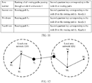
- FIG. 12 is an example of a schematic structural diagram of a local area network obtained through division in quantum communication according to an embodiment of this application.
- a quantum communication network may be divided into a plurality of local area networks, for example, a local area network 1201 and a local area network 1202 shown in FIG. 12 .
- a gateway node may be disposed in each local area network, and one or more gateway nodes may be disposed in each local area network.
- FIG. 12 only shows an example of disposing one gateway node in one local area network. As shown in FIG.
- the node M 1 may first send data to a gateway node S 1 in the local area network 1201, and then the gateway node S 1 in the local area network 1201 correspondingly sends the data to a gateway node S 2 in the local area network 1202, so that the gateway node S 2 forwards the data to the node M 6 in the local area network 1202.
- a source node may send data to a gateway node in a local area network including the source node, and then the gateway node in the local area network including the source node transmits the data to a gateway node in a local area network including a destination node, so that the gateway node in the local area network including the destination node transmits the data to the destination node.
- a routing path corresponding to a service request in each local area network may be calculated with assistance of a gateway node in the local area network, so that pressure of a centralized controller can be alleviated.
- an embodiment of this application provides a quantum communication method.
- a specific operation procedure is as follows:
- the encryption service request may include an encryption service request corresponding to a newly added service, or may include an encryption service request corresponding to a cancelled existing service.
- an encryption service request initiated by a node may be sent to the centralized controller, or may be sent to a gateway node in a local area network including the node.
- a centralized control end is disposed, and an encryption service request initiated by a node may be sent to the centralized control end.
- the centralized controller may plan a routing path corresponding to the encryption service request.
- the centralized controller may globally optimize the routing path during routing path planning.
- the centralized controller may be replaced with the centralized control end, or another device having a function of the centralized controller in this embodiment of this application.
- the gateway node may plan a routing path in the local area network including the gateway node.
- the centralized controller may plan routing paths between gateway nodes in different local area networks, so that pressure of the centralized controller can be alleviated.
- the routing path may be delivered to all nodes on the target routing path.
- a key update rate required for each encryption service may be further recorded.
- a plurality of parallel routing paths may be used to increase a final total key obtaining rate, or increase a weight on a specific routing path.
- the routing path may be optimized and adjusted based on a maximum key generation rate of each actual QKD link, so as to avoid a case in which key generation rates of many routing paths are limited because these routing paths pass through a same link.
- each node determines, based on information about a newly delivered routing path, a first correspondence and a second correspondence that corresponds to each node.
- a specific manner may be shown in the implementation a1 to the implementation b2. Details are not described herein again.
- each node still stores a historical first correspondence and a historical second correspondence
- the historical first correspondence and the historical second correspondence may be replaced with the newly obtained first correspondence and second correspondence.
- a destination node may properly process various types of information received in this time period.
- the node calculates, based on the updated first correspondence and the updated second correspondence, a third quantum key corresponding to the node on each routing path passing through the node, and after obtaining a calculation result, deletes, within preset duration, a first quantum key and a second quantum key that correspond to the node on each routing path passing through the node.
- the preset duration may be set to a relatively small value, for example, may be 1 minute or 30 seconds. Therefore, quantum key distribution can be improved.
- the node may publicize the third quantum key corresponding to the node on each routing path passing through the node, and related information of each routing path passing through the node.
- the node may publicize information in a plurality of manners. For example, the node may report the information only to a centralized control node, or may publicize information for internal use, in other words, among a specific group in a quantum network, or may publicize the information to a third party, for example, to a third-party supervision organization, or even may publicize the information to an entire network because the information does not affect security.
- the publicized information can help analyze a network status if being properly used, authentication needs to be performed when the information is publicized, to ensure that the information is sent by the current node.
- the publicized information may be further uploaded to a blockchain, to further prevent the publicized information from being tampered with.
- the source node may send a second ciphertext corresponding to the source node, where the node may publicize a third quantum key corresponding to the node on each routing path passing through the node, and related information of each routing path passing through the node.
- the destination node may obtain a to-be-shared quantum key between a source node and the destination node from a second ciphertext corresponding to the source node through decryption, where the node may publicize a third quantum key corresponding to the node on each routing path passing through the node, and related information of each routing path passing through the node.
- the to-be-shared quantum key may be stored in a service key pool, and the service key pool is confidential storage space.
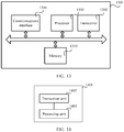
- FIG. 13 is an example of a schematic structural diagram of a quantum key distribution device according to this application.
- the quantum key distribution device 1301 includes a processor 1303, a transceiver 1302, a memory 1305, and a communications interface 1304.
- the processor 1303, the transceiver 1302, the memory 1305, and the communications interface 1304 are connected to each other by using a bus.
- the quantum key distribution device 1301 in this example may be an i th node on a routing path in the foregoing content.
- the quantum key distribution device 1301 may alternatively be a source node, a destination node, or a node on another routing path. This embodiment of this application is limited to a solution performed when the quantum key distribution device 1301 is used as a node.
- the memory 1305 may include a volatile memory (volatile memory) such as a random access memory (random-access memory, RAM), or the memory may include a nonvolatile memory (non-volatile memory) such as a flash memory (flash memory), a hard disk drive (hard disk drive, HDD), or a solid-state drive (solid-state drive, SSD), or the memory 1305 may include a combination of the foregoing types of memories.
- volatile memory such as a random access memory (random-access memory, RAM)
- nonvolatile memory such as a flash memory (flash memory), a hard disk drive (hard disk drive, HDD), or a solid-state drive (solid-state drive, SSD)
- flash memory flash memory
- HDD hard disk drive
- SSD solid-state drive
- the communications interface 1304 may be a wired communications interface, a wireless communications interface, or a combination thereof.
- the wired communications interface may be, for example, an Ethernet interface, and the Ethernet interface may be an optical interface, an electrical interface, or a combination thereof.
- the wireless communications interface may be a WLAN interface.
- the processor 1303 may be a central processing unit (central processing unit, CPU), a network processor (network processor, NP), or a combination of the CPU and the NP.
- the processor 1303 may further include a hardware chip.
- the foregoing hardware chip may be an application-specific integrated circuit (application-specific integrated circuit, ASIC), a programmable logic device (programmable logic device, PLD), or a combination thereof.
- the PLD may be a complex programmable logic device (complex programmable logic device, CPLD), a field-programmable logic gate array (field-programmable gate array, FPGA), generic array logic (generic array logic, GAL), or any combination thereof.
- the memory 1305 may be further configured to store a program instruction.
- the processor 1303 can perform one or more steps or an optional implementation in the embodiment in the foregoing solution by invoking the program instruction stored in the memory 1305, so that the quantum key distribution device 1301 implements functions of the i th node in the foregoing method.
- the quantum key distribution device is an i th node on a routing path of a quantum communication system.
- the processor 1303 in the quantum key distribution device is configured to: determine, based on a first correspondence, a first quantum key corresponding to the i th node on a target routing path; determine, based on a second correspondence, a second quantum key corresponding to the i th node on the target routing path; and generate, based on the first quantum key corresponding to the i th node on the target routing path and the second quantum key corresponding to the i th node on the target routing path, a third quantum key corresponding to the i th node on the target routing path, where the i th node is the i th node on the target routing path, the first quantum key corresponding to the i th node on the target routing path is a quantum key that is obtained by the i th node and that is to be shared between the i th node and an (i-1) th node on the target routing path, the first correspondence includes a correspondence between each of N routing paths passing through the i th node and
- the transceiver 1302 is configured to: send the third quantum key corresponding to the i th node on the target routing path to a target node on the target routing path; or encrypt, by using the processor by using the third quantum key corresponding to the i th node on the target routing path, a first ciphertext received from the (i-1) th node on the target routing path, and send an obtained second ciphertext corresponding to the i th node to the (i+1) th node on the target routing path.
- the first ciphertext received by the i th node from the (i-1) th node on the target routing path is a second ciphertext that is sent by the (i-1) th node and that corresponds to the (i-1) th node, and when i is 1, a 0 th node is a source node on the target routing path, and a second ciphertext corresponding to the source node on the target routing path is obtained by encrypting a to-be-shared quantum key between the source node on the target routing path and the target node on the target routing path by using a second quantum key corresponding to the source node on the target routing path.
- a second quantum key corresponding to the (i-1) th node on the target routing path is the same as the first quantum key corresponding to the i th node on the target routing path, and the second quantum key corresponding to the i th node on the target routing path is the same as a first quantum key corresponding to the (i+1) th node on the target routing path.
- N is an integer greater than 1
- a first quantum key corresponding to the i th node on the first routing path is different from a first quantum key corresponding to the i th node on the second routing path
- a second quantum key corresponding to the i th node on the first routing path is different from a second quantum key corresponding to the i th node on the second routing path.
- the transceiver 1302 is further configured to receive indication information that is sent by a centralized controller or the (i-1) th node on the target routing path and that is used to indicate the first quantum key on the target routing path corresponding to the i th node on the target routing path in the first correspondence; or the processor 1303 is further configured to determine, based on obtained network topology information of a quantum communication system and a first preset rule, the first quantum key on the target routing path corresponding to the i th node on the target routing path in the first correspondence.
- the first quantum key corresponding to the i th node on the target routing path is determined in a plurality of manners. For details, refer to the descriptions of the implementation a3-1, the implementation a3-2, and the implementation a3-3 in the foregoing content. Details are not described herein again.
- the transceiver 1302 is configured to receive indication information that is sent by the centralized controller or the (i+1) th node corresponding to the target routing path and that is used to indicate the second quantum key corresponding to the i th node on the target routing path in the second correspondence; or the processor 1303 is configured to determine, based on the obtained network topology information of the quantum communication system and a second preset rule, the second quantum key corresponding to the i th node on the target routing path in the second correspondence.
- the second quantum key corresponding to the i th node on the target routing path is determined in a plurality of manners. For details, refer to the descriptions of the implementation b3-1 and the implementation b3-2 in the foregoing content. Details are not described herein again.
- FIG. 14 is an example of a schematic structural diagram of a quantum key distribution device according to an embodiment of this application.
- a quantum key distribution device 1401 includes a transceiver unit 1402 and a processing unit 1403.
- the quantum key distribution device 1401 in this example may be an i th node on a routing path in the foregoing content.
- a person skilled in the art may learn that the quantum key distribution device 1401 may alternatively be a source node, a destination node, or a node on another routing path.
- This embodiment of this application is limited to a solution performed when the quantum key distribution device 1401 is used as a node.
- the processing unit 1403 is configured to: determine, based on a first correspondence, a first quantum key corresponding to the i th node on a target routing path; determine, based on a second correspondence, a second quantum key corresponding to the i th node on the target routing path; and generate, based on the first quantum key corresponding to the i th node on the target routing path and the second quantum key corresponding to the i th node on the target routing path, a third quantum key corresponding to the i th node on the target routing path, where the i th node is the i th node on the target routing path, the first quantum key corresponding to the i th node on the target routing path is a quantum key that is obtained by the i th node and that is to be shared between the i th node and an (i-1) th node on the target routing path, the first correspondence includes a correspondence between each of N routing paths passing through the i th node and each of N first quantum
- the instructions may be transmitted from a website, computer, server, or data center to another website, computer, server, or data center in a wired (for example, a coaxial cable, an optical fiber, or a digital subscriber line (DSL)) or wireless (for example, infrared, radio, or microwave) manner.
- the computer storage medium may be any usable medium accessible by the computer, or a data storage device, such as a server or a data center, integrating one or more usable media.
- the usable medium may be a magnetic medium (for example, a floppy disk, a hard disk, a magnetic tape, or a magneto-optical disc (MO)), an optical medium (for example, a CD, a DVD, a BD, or an HVD), a semiconductor medium (for example, a ROM, an EPROM, an EEPROM, a nonvolatile memory (NAND FLASH), or a solid state disk (Solid State Disk, SSD), or the like.
- a magnetic medium for example, a floppy disk, a hard disk, a magnetic tape, or a magneto-optical disc (MO)
- an optical medium for example, a CD, a DVD, a BD, or an HVD
- a semiconductor medium for example, a ROM, an EPROM, an EEPROM, a nonvolatile memory (NAND FLASH), or a solid state disk (Solid State Disk, SSD), or the like.
- SSD Solid State Disk
Landscapes
- Engineering & Computer Science (AREA)
- Computer Security & Cryptography (AREA)
- Computer Networks & Wireless Communication (AREA)
- Signal Processing (AREA)
- Physics & Mathematics (AREA)
- Theoretical Computer Science (AREA)
- Electromagnetism (AREA)
- Computing Systems (AREA)
- General Engineering & Computer Science (AREA)
- Computer Hardware Design (AREA)
- Data Exchanges In Wide-Area Networks (AREA)
- General Physics & Mathematics (AREA)
- Artificial Intelligence (AREA)
- Computational Mathematics (AREA)
- Condensed Matter Physics & Semiconductors (AREA)
- Data Mining & Analysis (AREA)
- Evolutionary Computation (AREA)
- Mathematical Analysis (AREA)
- Mathematical Optimization (AREA)
- Pure & Applied Mathematics (AREA)
- Mathematical Physics (AREA)
- Software Systems (AREA)
Abstract
Description
- This application claims priority to Chinese Patent Application No.
201810332715.5 - This application relates to the quantum communication field, and in particular, to a quantum key distribution method and device, and a storage medium.
- With development of science and technology, acceleration of informatization, and more frequent communication, an increasingly high requirement is posed on communication security. Secure quantum communication is a combination of a quantum feature and conventional cryptography, and uses a basic principle and feature of quantum mechanics to ensure communication security. After more than 30 years of development, secure quantum communication is practical in the market currently.
- Currently, the most practical secure quantum communication technology is a quantum key distribution (QKD) technology, and the quantum key distribution technology is used to implement unconditionally secure distribution of a symmetric key on the premise that some security keys have been shared.
FIG. 1 is a schematic diagram of a quantum key distribution method in the prior art. As shown inFIG. 1 , a routing path includes a source node A1, a relay node A2, a relay node A3, and a destination node A4, and K1 is a to-be-shared quantum key between the source node A1 and the destination node A4 and needs to be transmitted from the source node A1 to the destination node A4. In the prior art, the source node A1 encrypts K1 by using KA1A2, to obtain K2, and transmits obtained K2 to the relay node A2, where KA1A2 is a private key to be shared between the source node A1 and the relay node A2. The relay node A2 decrypts K2 by using KA1A2, then encrypts K1 by using KA2A3, to obtain K3, and transmits obtained K3 to the relay node A3, where KA2A3 is a private key to be shared between the relay node A2 and the relay node A3. The relay node A3 decrypts K3 by using KA2A3, then encrypts K1 by using KA3A4, to obtain K4, and transmits obtained K4 to the destination node A4, where KA3A4 is a private key to be shared between the relay node A3 and the destination node A4. The destination node A4 decrypts K4 by using KA3A4, to obtain K1. - In the solution shown in
FIG. 1 , the to-be-shared quantum key K1 between the source node A1 and the destination node A4 is decrypted by each intermediate node, and consequently security is relatively low. - Embodiments of this application provide a quantum key distribution method and device, and a storage medium, to resolve a prior-art problem of low security when a quantum key is distributed between nodes.
- According to a first aspect, an embodiment of this application provides a quantum key distribution method, where the method includes:
- determining, by an ith node based on a first correspondence, a first quantum key corresponding to the ith node on a target routing path, where the ith node is the ith node on the target routing path, the first quantum key corresponding to the ith node on the target routing path is a quantum key that is obtained by the ith node and that is to be shared between the ith node and an (i-1)th node on the target routing path, the first correspondence includes a correspondence between each of N routing paths passing through the ith node and each of N first quantum keys corresponding to the ith node, the N routing paths are in a one-to-one correspondence with the N first quantum keys corresponding to the ith node, the target routing path is one of the N routing paths, N is a positive integer, and i is a positive integer;
- determining, by the ith node based on a second correspondence, a second quantum key corresponding to the ith node on the target routing path, where the second quantum key corresponding to the ith node on the target routing path is a quantum key that is obtained by the ith node and that is to be shared between the ith node and an (i+1)111 node on the target routing path, the second correspondence includes a correspondence between each of the N routing paths passing through the ith node and each of N second quantum keys corresponding to the ith node, and the N routing paths are in a one-to-one correspondence with the N second quantum keys corresponding to the ith node;
- generating, by the ith node based on the first quantum key corresponding to the ith node on the target routing path and the second quantum key corresponding to the ith node on the target routing path, a third quantum key corresponding to the ith node on the target routing path; and
- sending, by the ith node, the third quantum key corresponding to the ith node on the target routing path to a target node on the target routing path; or encrypting, by the ith node by using the third quantum key corresponding to the ith node on the target routing path, a first ciphertext received from the (i-1)th node on the target routing path, and sending an obtained second ciphertext corresponding to the ith node to the (i+1) Ih node on the target routing path, where the first ciphertext received by the ith node from the (i-1)th node on the target routing path is a second ciphertext that is sent by the (i-1)th node and that corresponds to the (i-1)th node, and when i is 1, a 0th node is a source node on the target routing path, and a second ciphertext corresponding to the source node on the target routing path is obtained by encrypting a to-be-shared quantum key between the source node on the target routing path and the target node on the target routing path by using a second quantum key corresponding to the source node on the target routing path.
- A second quantum key corresponding to the (i-1)th node on the target routing path is the same as the first quantum key corresponding to the ith node on the target routing path, and the second quantum key corresponding to the ith node on the target routing path is the same as a first quantum key corresponding to the (i+1)th node on the target routing path.
- In this embodiment of this application, the second ciphertext corresponding to the source node on the target routing path is obtained by encrypting the to-be-shared quantum key between the source node on the target routing path and the target node on the target routing path by using the second quantum key corresponding to the source node on the target routing path. In addition, the second ciphertext that is sent by the (i-1)th node and that corresponds to the (i-1)th node is the first ciphertext received by the ith node from the (i-1)th node on the target routing path. The ith node sends the third quantum key corresponding to the ith node on the target routing path to the target node on the target routing path; or the ith node encrypts, by using the third quantum key corresponding to the ith node on the target routing path, the first ciphertext received from the (i-1)th node on the target routing path, and sends the obtained second ciphertext corresponding to the ith node to the (i+1)th node on the target routing path. It can be learned that the ith node does not decrypt the received first ciphertext. In other words, the to-be-shared quantum key between the source node and the target node on the target routing path is not obtained by a node through decryption. Therefore, quantum key distribution security is improved.
- In a possible implementation, if N is an integer greater than 1, for a first routing path and a second routing path in the N routing paths passing through the ith node, a first quantum key corresponding to the ith node on the first routing path is different from a first quantum key corresponding to the ith node on the second routing path; and a second quantum key corresponding to the ith node on the first routing path is different from a second quantum key corresponding to the ith node on the second routing path. Therefore, for each routing path, a node distributes a corresponding quantum key to the routing path to implement a one time system, so that quantum key distribution security can be further improved.
- In a possible implementation, before the determining, by an ith node based on a first correspondence, a first quantum key corresponding to the ith node on a target routing path, the method further includes: receiving, by the ith node, indication information that is sent by a centralized controller or the (i-1)th node on the target routing path and that is used to indicate the first quantum key on the target routing path corresponding to the ith node on the target routing path in the first correspondence; or determining, by the ith node based on obtained network topology information of a quantum communication system and a first preset rule, the first quantum key on the target routing path corresponding to the ith node on the target routing path in the first correspondence. It can be learned that a first quantum key corresponding to a node on a routing path may be determined by using a plurality of solutions, so as to improve solution flexibility.
- In a possible implementation, the determining, by the ith node based on obtained network topology information of a quantum communication system and a first preset rule, the first quantum key on the target routing path corresponding to the ith node on the target routing path in the first correspondence includes: determining, by the ith node based on a ranking relationship between numbers of N (i-1)th nodes on the N routing paths passing through the ith node, a ranking relationship between numbers of N (i+1)th nodes on the N routing paths passing through the ith node, and a ranking relationship between numbers of the N routing paths passing through the ith node, a ranking of the N routing paths passing through the ith node, and determining, based on the ranking of the N routing paths, the first quantum key corresponding to the ith node on the target routing path; or determining, by the ith node based on a ranking relationship between numbers of N (i+1)th nodes on the N routing paths passing through the ith node, and a ranking relationship between numbers of the N routing paths passing through the ith node, a ranking of the N routing paths passing through the ith node, and determining, based on the ranking of the N routing paths, the first quantum key corresponding to the ith node on the target routing path; or determining, by the ith node based on a ranking relationship between numbers of the N routing paths passing through the ith node, a ranking of the N routing paths passing through the ith node, and determining, based on the ranking of the N routing paths, the first quantum key corresponding to the ith node on the target routing path. It can be learned that a plurality of routing paths passing through the ith node may be ranked in a plurality of manners, and then the first quantum key corresponding to the ith node on the target routing path is determined based on the ranking of the routing paths. Therefore, convenience and flexibility of determining a first quantum key corresponding to an ith node on a routing path can be improved.
- In a possible implementation, before the determining, by the ith node based on a second correspondence, a second quantum key corresponding to the ith node on the target routing path, the method further includes: receiving, by the ith node, indication information that is sent by the centralized controller or the (i+1)th node corresponding to the target routing path and that is used to indicate the second quantum key corresponding to the ith node on the target routing path in the second correspondence; or determining, by the ith node based on the obtained network topology information of the quantum communication system and a second preset rule, the second quantum key corresponding to the ith node on the target routing path in the second correspondence. It can be learned that a second quantum key corresponding to a node on a routing path may be determined by using a plurality of solutions, so as to improve solution flexibility.
- In a possible implementation, the ith node determines, based on a ranking relationship between numbers of W routing paths passing through the ith node and the (i+1)th node on the target routing path, a ranking of the W routing paths passing through the ith node and the (i+1)111 node on the target routing path, and determines, based on the ranking of the W routing paths, the second quantum key corresponding to the ith node on the target routing path, where W is a positive integer that is not greater than N; or the ith node determines, based on a ranking relationship between numbers of W (i+2)th nodes on W routing paths passing through the ith node and the (i+1)111 node on the target routing path, and a ranking relationship between numbers of the W routing paths passing through the ith node and the (i+1)111 node on the target routing path, a ranking of the W routing paths passing through the ith node and the (i+1)th node on the target routing path, and determines, based on the ranking of the W routing paths, the second quantum key corresponding to the ith node on the target routing path. It can be learned that a plurality of routing paths passing through the ith node may be ranked in a plurality of manners, and then the second quantum key corresponding to the ith node on the target routing path is determined based on the ranking of the routing paths. Therefore, convenience and flexibility of determining a second quantum key corresponding to an ith node on a routing path can be improved.
- In a possible implementation, a first algorithm used when the ith node encrypts, by using the third quantum key corresponding to the ith node on the target routing path, the first ciphertext received from the (i-1)th node on the target routing path meets a formula (1) in subsequent specific embodiments. Therefore, after decrypting the received first ciphertext, the destination node can obtain the to-be-shared quantum key. For a detailed analysis process, refer to descriptions in subsequent specific embodiments. Details are not described herein.
- According to a second aspect, an embodiment of this application provides a quantum key distribution device. The quantum key distribution device includes a memory, a transceiver, and a processor. The memory is configured to store an instruction. The processor is configured to: execute the instruction stored in the memory, and control the transceiver to receive a signal and send a signal. When the processor executes the instruction stored in the memory, the quantum key distribution device is configured to perform the method in any one of the first aspect or the possible implementations of the first aspect.
- According to a third aspect, an embodiment of this application provides a quantum key distribution device, configured to implement the method in any one of the first aspect or the possible implementations of the first aspect. The quantum key distribution device includes corresponding functions separately configured to implement steps in the foregoing method. The functions may be implemented by hardware, or may be implemented by hardware executing corresponding software. The hardware or software includes one or more modules corresponding to the foregoing functions.
- In a possible design, a structure of the quantum key distribution device includes a processing unit and a transceiver unit. These units can execute corresponding functions in the foregoing method example. For details, refer to the detailed descriptions in the method example. Details are not described herein again.
- According to a fourth aspect, an embodiment of this application provides a computer storage medium. The computer storage medium stores an instruction. When the instruction is run on a computer, the computer is enabled to perform the method in any one of the first aspect or the possible implementations of the first aspect.
- According to a fifth aspect, an embodiment of this application provides a computer program product including an instruction. When the computer program product is run on a computer, the computer is enabled to perform the method in any one of the first aspect or the possible implementations of the first aspect.
-
-
FIG. 1 is a schematic diagram of a quantum key distribution method in the prior art; -
FIG. 2 is a schematic architectural diagram of a quantum communication system according to an embodiment of this application; -
FIG. 3 is a schematic flowchart of a quantum key distribution method according to an embodiment of this application; -
FIG. 4 is a schematic diagram of a quantum key distribution method performed for a routing path L2 inFIG. 2 according to an embodiment of this application; -
FIG. 5 is a schematic diagram of another quantum key distribution method performed for a routing path L2 inFIG. 2 according to an embodiment of this application; -
FIG. 6 is a schematic diagram in which a node D inFIG. 2 generates, in an implementation a3-1, a first correspondence corresponding to the node D according to an embodiment of this application; -
FIG. 7 is a schematic diagram in which a node D inFIG. 2 generates, in an implementation a3-2, a first quantum key corresponding to the node D on a routing path L2 according to an embodiment of this application; -
FIG. 8 is a schematic diagram in which a node D inFIG. 2 generates, in an implementation a3-3, a first quantum key corresponding to the node D on a routing path L2 according to an embodiment of this application; -
FIG. 9 is a schematic diagram in which a node D inFIG. 2 generates, in an implementation b3-1, a second correspondence corresponding to the node D according to an embodiment of this application; -
FIG. 10 is a schematic diagram in which a node E inFIG. 2 generates, in an implementation a3-1, a first correspondence corresponding to the node E according to an embodiment of this application; -
FIG. 11 is a schematic diagram in which a node D inFIG. 2 generates, in an implementation b3-2, a second quantum key corresponding to the node D on a routing path L2 according to an embodiment of this application; -
FIG. 12 is a schematic structural diagram of a local area network obtained through division in quantum communication according to an embodiment of this application; -
FIG. 13 is a schematic structural diagram of a quantum key distribution device according to an embodiment of this application; and -
FIG. 14 is a schematic structural diagram of another quantum key distribution device according to an embodiment of this application. -
FIG. 2 is an example of a schematic architectural diagram of a quantum communication system according to an embodiment of this application. As shown inFIG. 2 , the quantum communication system includes a plurality of nodes, for example, a node B, a node C, a node D, a node E, a node F, a node G, a node H, a node P, a node Q, and a node R. There may be a plurality of routing paths between the plurality of nodes, and a node other than a source node and a destination node on one routing path may be referred to as a relay node. One node may be used as a source node on one routing path and used as a relay node or a destination node on another routing path.FIG. 2 shows several routing paths as an example, which are respectively: - a routing path L1: "source node B->relay node D->relay node E->relay node G->destination node P";
- a routing path L2: "source node B->relay node D->relay node E->relay node G->destination node Q";
- a routing path L3: "source node B->relay node D->relay node E->destination node H";
- a routing path L4: "source node C->relay node D->destination node F";
- a routing path L5: "source node B->relay node D->destination node F"; and
- a routing path L6: "source node R->relay node E->destination node H".
- Based on the schematic architectural diagram of the quantum communication shown in
FIG. 2 , an embodiment of this application provides a quantum key distribution method.FIG. 3 is an example of a schematic flowchart of a quantum key distribution method according to an embodiment of this application. As shown inFIG. 3 , the method provided in this embodiment of this application includes the following steps. - Step 301: An ith node determines, based on a first correspondence, a first quantum key corresponding to the ith node on a target routing path. In an optional implementation, the ith node is an ith relay node on the target routing path.
- The ith node is the ith node on the target routing path. The first quantum key corresponding to the ith node on the target routing path is a quantum key that is obtained by the ith node and that is to be shared between the ith node and an (i-1)th node on the target routing path. The first correspondence includes a correspondence between each of N routing paths passing through the ith node and each of N first quantum keys corresponding to the ith node, and the N routing paths are in a one-to-one correspondence with the N first quantum keys corresponding to the ith node, where N is a positive integer, and i is a positive integer. The target routing path is any one of the N routing paths. In this embodiment of this application, the target routing path is merely a name for ease of description, and does not constitute a limitation.
- Step 302: The ith node determines, based on a second correspondence, a second quantum key corresponding to the ith node on the target routing path.
- The second quantum key corresponding to the ith node on the target routing path is a quantum key that is obtained by the ith node and that is to be shared between the ith node and an (i+1)th node on the target routing path. The second correspondence includes a correspondence between each of the N routing paths passing through the ith node and each of N second quantum keys corresponding to the ith node, and the N routing paths are in a one-to-one correspondence with the N second quantum keys corresponding to the ith node.
- Step 303: The ith node generates, based on the first quantum key corresponding to the ith node on the target routing path and the second quantum key corresponding to the ith node on the target routing path, a third quantum key corresponding to the ith node on the target routing path. After
step 303, this embodiment of this application provides two optional implementations. In one optional implementations,step 304 is performed afterstep 303. In the other optional implementations,step 305 is performed afterstep 303. Whetherstep 304 or step 305 is performed afterstep 303 may be flexibly selected by a person skilled in the art based on an actual application scenario. - Step 304: The ith node sends the third quantum key corresponding to the ith node on the target routing path to a target node on the target routing path.
- Step 305: The ith node encrypts, by using the third quantum key corresponding to the ith node on the target routing path, a first ciphertext received from the (i-1)th node on the target routing path, and sends an obtained second ciphertext corresponding to the ith node to the (i+1)th node on the target routing path.
- The first ciphertext received by the ith node from the (i-1)th node on the target routing path is a second ciphertext that is sent by the (i-1)th node and that corresponds to the (i-1)th node. When i is 1, a 0th node is a source node on the target routing path, and a second ciphertext corresponding to the source node on the target routing path is obtained by encrypting a to-be-shared quantum key between the source node on the target routing path and the target node on the target routing path by using a second quantum key corresponding to the source node on the target routing path.
- A second quantum key corresponding to the (i-1)th node on the target routing path is the same as the first quantum key corresponding to the ith node on the target routing path, and the second quantum key corresponding to the ith node on the target routing path is the same as a first quantum key corresponding to the (i+1)th node on the target routing path.
- In this embodiment of this application, an algorithm used when the ith node encrypts, by using the third quantum key corresponding to the ith node on the target routing path, the first ciphertext received from the (i-1)th node on the target routing path may be referred to as a first algorithm. In this embodiment of this application, an algorithm used when the third quantum key corresponding to the ith node on the target routing path is generated based on the first quantum key corresponding to the ith node on the target routing path and the second quantum key corresponding to the ith node on the target routing path may be referred to as a second algorithm.
- The quantum key distribution method shown in
FIG. 3 is described in detail below by using an example in which the target routing path is the routing path L2 inFIG. 2 .FIG. 4 is an example of a schematic diagram of a quantum key distribution method performed for a routing path L2 inFIG. 2 . A solution shown inFIG. 4 is used to perform a solution corresponding to step 305. As shown inFIG. 4 , a to-be-shared quantum key between the source node B and the destination node Q is KBQ(L2), and the source node B needs to transmit the to-be-shared quantum key KBQ(L2) to the destination node Q. A specific procedure is as follows: - As shown in
FIG. 4 , for the source node, the source node B obtains the to-be-shared quantum key KBQ(L2). A second quantum key corresponding to the source node B is a quantum key that corresponds to the source node B on the routing path L2 and that is to be shared between the source node B and the relay node D, where the quantum key is determined by the source node B. InFIG. 4 , KBD(L2) represents the second quantum key corresponding to the source node B on the routing path L2. - The source node B encrypts, by using the second quantum key KBD(L2) corresponding to the source node B, the to-be-shared quantum key KBQ(L2) between the source node on the target routing path and the target node on the target routing path, to obtain a second ciphertext KB(L2) corresponding to the source node B. The source node B sends the second ciphertext KB(L2) corresponding to the source node to the relay node D. An algorithm used to encrypt KBQ(L2) by using KBD(L2) may be referred to as a third algorithm. The third algorithm may be the same as the first algorithm, or may be another algorithm.
- Correspondingly, the relay node D receives a first ciphertext KB(L2) from the source node B. In other words, the second ciphertext that is sent by the source node B and that corresponds to the source node B is the same as the first ciphertext received by the relay node D. In this embodiment of this application, a first ciphertext received by a relay node may also be referred to as the first ciphertext corresponding to the relay node. For example, the first ciphertext KB(L2) received by the relay node D may also be referred to as the first ciphertext KB(L2) corresponding to the relay node D. If the target routing path is the routing path L2, and the node D is an ith node on the target routing path, the node B is an (i-1)th node on the target routing path, the node E is an (i+1)th node on the target routing path, and the node G is an (i+2)th node on the target routing path. This is the same for subsequent descriptions, and is not described below. The relay node D generates, based on a first quantum key KDB(L2) corresponding to the relay node D on the target routing path and a second quantum key KDE(L2) corresponding to the relay node D on the target routing path, a third quantum key KBE(L2) corresponding to the relay node D on the target routing path.
- Further, the relay node D encrypts, by using the third quantum key KBE(L2), the received first ciphertext KB(L2) corresponding to the relay node D, to obtain a second ciphertext KD(L2) corresponding to the relay node D. The relay node D sends the second ciphertext KD(L2) corresponding to the relay node D to the relay node E. An algorithm used to encrypt the first ciphertext KB(L2) by using the third quantum key KBE(L2) to generate the second ciphertext KD(L2) may be the first algorithm.
- Correspondingly, the relay node E receives a first ciphertext KD(L2) from the relay node D. In other words, the second ciphertext that is sent by the relay node D and that corresponds to the relay node D is the same as the first ciphertext received by the relay node E. The relay node E generates, based on a first quantum key KED(L2) corresponding to the relay node E on the routing path L2 and a second quantum key KEG(L2) corresponding to the relay node E on the routing path L2, a third quantum key KDG(L2) corresponding to the relay node E on the routing path L2. Further, the relay node E encrypts the first ciphertext KD(L2) by using the third quantum key KDG(L2), to obtain a second ciphertext KE(L2) corresponding to the relay node E. The relay node E sends the second ciphertext KE(L2) corresponding to the relay node E to the relay node G.
- Correspondingly, the relay node G receives a first ciphertext KE(L2) from the relay node E. In other words, the second ciphertext that is sent by the relay node E and that corresponds to the relay node E is the same as the first ciphertext received by the relay node G. The relay node G generates, based on a first quantum key KGE(L2) corresponding to the relay node G on the routing path L2 and a second quantum key KGQ(L2) corresponding to the relay node G on the routing path L2, a third quantum key KEQ(L2) corresponding to the relay node G on the routing path L2. Further, the relay node G encrypts the first ciphertext KE(L2) by using the third quantum key KEQ(L2), to obtain a second ciphertext KG(L2) corresponding to the relay node G. The relay node G sends the second ciphertext KG(L2) corresponding to the relay node G to the relay node Q.
- Further, the destination node Q receives a first ciphertext KG(L2) from the relay node G, and KG(L2) may be referred to as the first ciphertext corresponding to the destination node Q. The destination node Q decrypts the first ciphertext KG(L2) by using a first quantum key KQG(L2) corresponding to the destination node Q on the routing path L2, to obtain the to-be-shared quantum key KBQ(L2). An algorithm used for decryption processing may be referred to as a fourth algorithm. The fourth algorithm may be the same as the first algorithm, or may be another algorithm.
- For a process in which the destination node decrypts, by using the first quantum key corresponding to the destination node on the target routing path, the first ciphertext corresponding to the destination node, to obtain the to-be-shared quantum key, refer to related descriptions of a formula (1) in the following content.
-
FIG. 5 is an example of a schematic diagram of another quantum key distribution method performed for a routing path L2L2 inFIG. 2 . The solution shown inFIG. 4 is used to perform a solution corresponding to step 304. As shown inFIG. 5 , the source node may send generated KB(L2) to the destination node Q by using a typical signal or through a quantum channel. Each relay node also sends a third quantum key correspondingly generated by each relay node to the destination node Q. For example, inFIG. 5 , the relay node D sends a generated third quantum key KBE(L2) corresponding to the relay node D on the routing path L2 to the destination node Q, the relay node E sends a generated third quantum key KDG(L2) corresponding to the relay node E on the routing path L2 to the destination node Q, and the relay node G sends a generated third quantum key KEQ(L2) corresponding to the relay node G on the routing path L2 to the destination node Q. The destination node Q encrypts KB(L2) by using KBE(L2), encrypts an obtained result by using KDG(L2), encrypts an obtained result by using KEQ(L2), and decrypts an obtained result by using KQG(L2), to obtain a to-be-shared quantum key KBQ(L2). It can be learned that, in this solution, each relay node sends the third quantum key to the destination node after obtaining the third quantum key through calculation, so that operation duration of each relay node can be shortened, and quantum key distribution efficiency can be further improved. - The following content can be learned from the examples shown in
FIG. 4 andFIG. 5 . First, in this embodiment of this application, a relay node does not decrypt information sent by a previous node of the relay node, so that a to-be-shared quantum key between a source node and a destination node is not obtained by a relay node through decryption, in other words, the relay node does not obtain the to-be-shared quantum key between the source node and the destination node through decryption. This can improve security of the to-be-shared quantum key between the source node and the destination node. - Second, a relay node does not encrypt and decrypt information sent by a previous node of the relay node, so that a time and a resource occupied for performing optical-to-electrical conversion on a to-be-shared quantum key on a routing path can be saved.
- Third, in this embodiment of this application, after generating a third quantum key, a relay node may delete a first quantum key and a second quantum key that correspond to the relay node. It can be learned that the relay node may not leave a time window within which an attack is made, so that a capability of an eavesdropper for decrypting a to-be-shared quantum key is deteriorated. This can further improve information transmission security in a quantum key distribution process.
- Fourth, related information of a third quantum key corresponding to a relay node may be publicized, so that an information storage security requirement can be lowered. This provides a basis for further publicizing all related attribute information of the relay node. A node may publicize a log including a corresponding operation and a corresponding access status that are generated when the node is used as a relay node on a routing path, and a resource utilization status of the chip. In this process, an intermediate step of obtaining a third quantum key corresponding to the relay node through calculation and a related information result used in the intermediate step cannot be publicized. In this embodiment of this application, the relay node may publicize related information of the relay node, for example, a log including an operation and an access status of the relay node. This can help analyze a network running status, and further improves transparency to a customer.
- In this embodiment of this application, the second quantum key corresponding to the (i-1)th node on the target routing path is the same as the first quantum key corresponding to the ith node on the target routing path, and the second quantum key corresponding to the ith node on the target routing path is the same as the first quantum key corresponding to the (i+1)th node on the target routing path. For example, in
FIG. 4 , KBD(L2) is the same as KDB(L2), KDE(L2) is the same as KED(L2), KEG(L2) is the same as KGE(L2), and KGQ(L2) is the same as KQG(L2). Therefore, the destination node can obtain the to-be-shared quantum key through decryption. - In
FIG. 4 andFIG. 5 , an example in which both the first algorithm and the second algorithm are exclusive OR algorithms is used for description. A person skilled in the art may learn that the first algorithm and the second algorithm may alternatively be other algorithms. Instep 303, an algorithm used when the third quantum key corresponding to the ith node on the target routing path is generated based on the first quantum key corresponding to the ith node on the target routing path and the second quantum key corresponding to the ith node on the target routing path is the second algorithm, and an algorithm used when the ith node encrypts, by using the third quantum key corresponding to the ith node on the target routing path, the first ciphertext received from the (i-1)th node on the target routing path is the first algorithm. - In an optional implementation, the first algorithm meets the formula (1):

- In the formula (1), L j is an identifier of the target routing path;
- K i-1,i-2 (Lj ) is a first quantum key corresponding to the (i-1)th node on the target routing path L j ;
- K i-1,i (L j ) is the second quantum key corresponding to the (i-1)th node on the target routing path L j ;
- K i,i-1 (Lj ) is the first quantum key corresponding to the ith node on the target routing path Lj ;
- K i,i+1(Lj ) is the second quantum key corresponding to the ith node on the target routing path;
- fE (•) is a function corresponding to the second algorithm, where the second algorithm is an algorithm used when the third quantum key corresponding to the ith node on the target routing path is generated based on the first quantum key corresponding to the ith node on the target routing path and the second quantum key corresponding to the ith node on the target routing path; and
- g (•) is a function corresponding to the first algorithm.
- With reference to
FIG. 4 , for example, when the ith node is the relay node E, the foregoing formula (1) may be correspondingly expressed as follows:
- Herein, fE (KDB (L 2), KDE (L 2)) means that an operation corresponding to the second algorithm is performed on the first quantum key KDB(L2) corresponding to the relay node D on the routing path L2 and the second quantum key KDE(L2) corresponding to the relay node D on the routing path L2, and a calculation result of fE (KDB (L2 ), kDE (L 2)) is the third quantum key KBE(L2), shown in
FIG. 4 , corresponding to the relay node D on the routing path L2. - fE (KED (L2 ), KEG (L 2)) means that an operation corresponding to the second algorithm is performed on the first quantum key KED(L2) corresponding to the relay node E on the routing path L2 and the second quantum key KEG(L2) corresponding to the relay node E on the routing path L2, and a calculation result of fE (KED (L2 ), KEG (L 2)) is the third quantum key KDG(L2), shown in
FIG. 4 , corresponding to the relay node E on the routing path L2. - g(fE (KDB (L2 ), KDE (L 2)), fE (KED (L2 ), KEG (L 2))) means that an operation corresponding to the first algorithm is performed on the third quantum key KBE(L2) corresponding to the relay node D on the routing path L2 and the third quantum key KDG(L2) corresponding to the relay node E on the routing path L2, and when KDE(L2) is the same as KED(L2), a result of g(fE (KDB (L2 ), KDE(L 2)), fE (KED (L 2), KEG (L 2))) is fE (KDB(L 2), KEG (L 2)).
- When the foregoing formula (1) is used, with reference to a calculation manner of a third quantum key corresponding to each node in
FIG. 4 and a calculation manner of a second ciphertext corresponding to each node inFIG. 4 , descriptions are provided as an example with reference toFIG. 4 . An operation performed by the destination node Q may be expressed by using the following formula (2):
- It can be learned from the formula (2) that, after performing an operation on the received first ciphertext, the destination node may obtain the to-be-shared quantum key. A person skilled in the art may learn that, in an actual operation, the destination node may not perform the detailed calculation shown in the foregoing formula (2), but performs, by using KQG(L2), only the operation corresponding to the first algorithm on received KG(L2).
- In
FIG. 4 andFIG. 5 , only an example in which the first algorithm, the second algorithm, the third algorithm, and the fourth algorithm are all exclusive OR algorithms is used for description. In a specific implementation process, the first algorithm, the second algorithm, the third algorithm, and the fourth algorithm are implemented in a plurality of manners. For example, two first algorithms correspondingly used by two nodes are two different algorithms, or two second algorithms correspondingly used by two nodes are two different algorithms. - For example, fE (•) may be a function set, may include a series of encryption functions {f E0, f E1 ...}, and may further include a decryption function fD . f E0 is the foregoing third algorithm used to encrypt a to-be-shared quantum key between the source node and the destination node, and f E1, f E2... is a function used by each relay node to calculate a third quantum key and encrypt a received first ciphertext. In other words, a function corresponding to the first algorithm is the same as a function corresponding to the second algorithm (for example, f E1 is a function used by the first relay node on a routing path to calculate a third quantum key corresponding to the first relay node and encrypt a received first ciphertext). fD is the fourth algorithm. In other words, the destination node decrypts a received first ciphertext, to obtain a to-be-shared quantum key. Any two functions in {f E0, f E1...} and fD may be the same or may be different. This is not limited in this embodiment of this application.
- It can be learned from the foregoing example that, in this embodiment of this application, when a quantum key to be shared between two adjacent nodes used in a quantum key distribution process is unknown (for example, a quantum key to be shared between the destination node and a previous node of the destination node is unknown), the to-be-shared quantum key cannot be obtained through calculation by using obtained third quantum keys of some or all nodes and an obtained second ciphertext sent by the source node, so that security of the quantum key distribution process can be improved.
- An optional implementation of the first algorithm and the second algorithm is further enumerated in this embodiment of this application. For example, the second algorithm may be defined as an operation of performing modulo 4 subtraction on every two bits. Details are as follows:
- For example, for any function in {f E0, f E1...} in the function set fE (•), an input is two binary sequences whose lengths each are 2n, for example, X = x 1 x 2 ...x 2k-1 x 2 k...x 2n-1 x 2 n, Y = y 1 y 2 ...y 2k-1 y 2 k...y 2n-1 y2n , and an output is still one binary sequence whose length is 2n, for example, Z = z 1 z 2...z2k-1z2 k....z 2n-1z2n = fE (X,Y). In this case, z 2 k- 1z2k may be obtained by using the following calculation method:
- calculating a function " ak = 2x 2k-1 + x 2 k, bk = 2y 2k-1 + Y 2k "; and
- if ak ≥ bk , determining that z 2k-1z2k is a binary representation of ak - bk ; or if ak < bk , determining that z 2k-1z2k is a binary representation of ak - bk + 4 .
- However, the decryption function fD may be an operation of performing modulo 4 addition on every two bits, and it is not difficult to verify that the function in this example may also meet the foregoing implementations. It should be further noted that the foregoing formula (1) is not a necessary and sufficient condition for meeting the solution provided in this embodiment of this application, but is only a sufficient condition. Alternatively, there may be another form of function that meets a mathematical feature in the foregoing embodiment. This is not limited in this embodiment of this application.
- The communications system applicable to this embodiment of this application may include a plurality of routing paths. If N is an integer greater than 1, for a first routing path and a second routing path in N routing paths passing through an ith node, a first quantum key corresponding to the ith node on the first routing path is different from a first quantum key corresponding to the ith node on the second routing path, and a second quantum key corresponding to the ith node on the first routing path is different from a second quantum key corresponding to the ith node on the second routing path. The first routing path and the second routing path are two different routing paths in the N routing paths. As shown in
FIG. 2 , there are five routing paths passing through the relay node D, and for any two of the five routing paths, for example, the routing path L1 and the routing path L5, a first quantum key corresponding to the relay node D on the routing path L1 is different from a first quantum key corresponding to the relay node D on the routing path L5, and a second quantum key corresponding to the relay node D on the routing path L1 is different from a second quantum key corresponding to the relay node D on the routing path L5. In other words, for each routing path, a node distributes a corresponding quantum key to the routing path, to implement a one time system, so that quantum key distribution security can be further improved. In addition, this embodiment of this application is applicable to a multipath case, and a network to which this embodiment of this application is applied may be more complex. - In actual application, the quantum communication system continuously generates quantum keys to push the quantum keys to a key management layer. Therefore, each quantum key may be numbered, and the number corresponding to the quantum key may also be referred to as an identifier corresponding to the quantum key. For example, in
FIG. 2 , quantum keys KDE are continuously generated between the node D and the node E, a length of a quantum key may be 256 bits, and a number of each quantum key corresponds to one 256-bit quantum key. There are a plurality of routing paths passing through the node D and the node E, for example, the routing path L1, the routing path L2, and the routing path L3 shown inFIG. 2 . In this case, the node D and the node E need to separately distribute the quantum keys generated between the node D and the node E to the routing path L1, the routing path L2, and the routing path L3. In this embodiment of this application, a second quantum key distributed by the node D to a routing path and a first quantum key distributed by the node E to the target routing path need to be a same quantum key. For example, a second quantum key distributed by the node D to the routing path L1 and a first quantum key distributed by the node E to the routing path L1 need to be a same quantum key. To meet this requirement, the first correspondence may be obtained beforestep 301, and the second correspondence may be obtained beforestep 302. The first correspondence and the second correspondence may be represented in a plurality of forms, for example, in a table form or in a text form. This is not limited in this embodiment of this application. The following content is described by using a table form as an example. - The first correspondence in
step 301 and the second correspondence instep 302 may be obtained in a plurality of manners. The following describes several manners of obtaining the first quantum key corresponding to the ith node on the routing path in the first correspondence: an optional implementation a1, an optional implementation a2, and an optional implementation a3. - In the implementation a1, indication information used to indicate the first quantum key corresponding to the ith node on the target routing path in the first correspondence is delivered by a centralized controller.
- The ith node receives the indication information that is sent by the centralized controller and that is used to indicate the first quantum key corresponding to the ith node on the target routing path. In this embodiment of this application, the indication information used to indicate the first quantum key corresponding to the ith node on the target routing path may be directly the first quantum key corresponding to the ith node on the target routing path, or may be other information that can indicate the correspondence. Optionally, the ith node receives indication information that is sent by the centralized controller and that is used to indicate the second quantum key corresponding to the ith node on the target routing path. The centralized controller may collect service requests in an entire network, and may better calculate a routing path in the entire network. Subsequently, the centralized controller may calculate a first correspondence corresponding to each node when the node is used as a node, and then deliver the first correspondence to each node.
- In the implementation a2, indication information used to indicate the first quantum key corresponding to the ith node on the target routing path in the first correspondence is sent by the (i-1)th node on the target routing path.
- In this implementation, the (i-1)th node on the routing path may obtain the second quantum key corresponding to the (i-1)th node on the target routing path through calculation, and then send the second quantum key to the ith node. Because the second quantum key corresponding to the (i-1)th node on the target routing path is the same as the first quantum key corresponding to the ith node on the target routing path, the ith node may learn of the first quantum key corresponding to the ith node on the target routing path in the first correspondence.
- Based on this implementation, in an optional implementation, each node (other than the target node) on the target routing path obtains a second quantum key corresponding to each node on the target routing path through calculation, and then sends the second quantum key corresponding to each node on the target routing path to a next node of each node on the target routing path. Because the second quantum key corresponding to each node on the target routing path is the same as a first quantum key corresponding to the next node of each node on the target routing path, the node on the target routing path may obtain, in the implementation a2, the first quantum key corresponding to the ith node on the routing path in the first correspondence.
- In the implementation a3, the ith node determines, based on obtained network topology information of the quantum communication system and a first preset rule, the first quantum key corresponding to the ith node on the target routing path.
- For the implementation a3, there may be a plurality of implementations in which the ith node determines, based on the obtained network topology information of the quantum communication system and the first preset rule, the first quantum key corresponding to the ith node on the target routing path. The following describes an optional implementation a3-1, an optional implementation a3-2, and an optional implementation a3-3.
- The ith node determines, based on a ranking relationship between numbers of a plurality of (i-1)th nodes on the N routing paths passing through the ith node, a ranking relationship between numbers of N (i+1)th nodes on a plurality of routing paths passing through the ith node, and a ranking relationship between numbers of the N routing paths passing through the ith node, a ranking of the plurality of routing paths passing through the ith node, and determines, based on the ranking of the plurality of routing paths, the first quantum key corresponding to the ith node on the target routing path.
-
FIG. 6 is an example of a schematic diagram in which the node D inFIG. 2 generates, in the implementation a3-1, a first correspondence corresponding to the node D. As shown inFIG. 6 , in the six routing paths shown inFIG. 2 , each node has a global number. Optionally, there may be a ranking relationship between global numbers of the nodes. For example, the global numbers of the nodes may be represented by Arabic numerals, letters, or some characters having a preset ranking relationship. InFIG. 2 , it is assumed that letters corresponding to the nodes are ranked in a letter ranking sequence in an alphabet. As shown inFIG. 6 , all paths on which the node D is used as a relay node are the routing path L1 to the routing path L5, and previous-hop nodes of the node D on the five routing paths are first ranked. As shown inFIG. 6 , there are two previous-hop nodes of the node D: the node B and the node C, and a ranking result is shown in the second column inFIG. 6 . - Further, next-hop nodes of the node D on four routing paths on which the previous-hop node of the node D is the node B are ranked. As shown in
FIG. 6 , when the previous-hop node of the node D is the node B, the next-hop nodes of the node D are the node E and the node F, and a ranking result is shown in the second row to the fifth row in the third column inFIG. 6 . A next-hop node of the node C on one routing path on which the previous-hop node of the node D is the node C is ranked. As shown inFIG. 6 , when the previous-hop node of the node D is the node C, the next-hop node of the node D is the node F, and a ranking result is shown in the sixth row in the third column inFIG. 6 . - Further, when there are a plurality of routing paths passing through a same previous-hop node of the node D and a same next-hop node of the node D, the plurality of routing paths may be ranked based on global numbers of the routing paths. Optionally, each routing path may have a global number, and there may be a ranking relationship between the numbers of the routing paths. It is assumed that global numbers of the six routing paths in
FIG. 2 are ranked from L1 to L6. As shown inFIG. 6 , there are three routing paths passing through the node B, the node D, and the node E: the routing path L1, the routing path L2, and the routing path L3, and the routing path L1, the routing path L2, and the routing path L3 are ranked in the second row to the fourth row in the fourth column based on a ranking relationship between global numbers of the routing path L1, the routing path L2, and the routing path L3. There is only one routing path passing through the node B, the node D, and the node F, and the routing path is ranked in the fifth row in the third column inFIG. 6 . There is also only one routing path passing through the node C, the node D, and the node F, and the routing path is ranked in the sixth row in the third column inFIG. 6 . - It can be learned from
FIG. 6 that the node D has ranked all routing paths passing through the node D, and then may sequentially distribute quantum keys to the routing paths based on the ranking relationship. As shown in the fourth column inFIG. 6 , the second row and the third row in the fourth column inFIG. 6 are used as an example for description. A first quantum key distributed by the node D to the routing path L1 is KDB(L1), and a first quantum key distributed by the node D to the routing path L2 is KDB(L2). - Optionally, because consumption of a quantum key on a specific routing path may be relatively high, a weight may be set for each routing path based on consumption of a quantum key on each routing path and/or service attribute information, to determine a quantity of quantum keys distributed to each routing path in each quantum key distribution period. In other words, KDB(L1) is only an identifier corresponding to the first quantum key distributed by the node D to the routing path L1. When only one quantum key is distributed to the routing path L1 in one quantum key distribution period, assuming that a length of a quantum key is 256 bits, KDB(L1) may be an identifier corresponding to a 256-bit quantum key in each quantum key distribution period. If a plurality of (for example, three) quantum keys are distributed to the routing path L1 in one quantum key distribution period, assuming that a length of a quantum key is 256 bits, KDB(L1) may be identifiers corresponding to the three 256-bit quantum keys in each quantum key distribution period.
- During specific implementation, routing paths are flexibly ranked.
FIG. 6 only shows a possible implementation, and there may be another implementation. For example, a plurality of (i+1)th nodes are first ranked based on a ranking relationship between numbers of the plurality of (i+1)th nodes on a plurality of routing paths passing through the ith node, then a plurality of (i-1)th nodes are ranked based on a ranking relationship between numbers of the plurality of (i-1)th nodes on the plurality of routing paths passing through the ith node, and finally the plurality of routing paths are ranked based on a ranking relationship between numbers of the plurality of routing paths passing through the ith node. Details are not described herein. - The ith node determines, based on a ranking relationship between numbers of a plurality of (i+1)th nodes on the N routing paths passing through the ith node, and a ranking relationship between numbers of the N routing paths passing through the ith node, a ranking of a plurality of routing paths passing through the ith node, and determines, based on the ranking of the plurality of routing paths, the first quantum key corresponding to the ith node on the target routing path.
-
FIG. 7 is an example of a schematic diagram in which the node D inFIG. 2 generates, in the implementation a3-2, a first quantum key corresponding to the node D on the routing path L2. As shown inFIG. 7 , in this example, a plurality of routing paths passing through the node D may be first determined: the routing path L1, the routing path L2, the routing path L3, the routing path L4, and the routing path L5. Then, next-hop nodes of the node D on the routing path L1, the routing path L2, the routing path L3, the routing path L4, and the routing path L5 may be ranked, where a ranking result is shown in the second row to the sixth row in the second column inFIG. 7 , and the next-hop nodes on the plurality of routing paths passing through the node D are the node E and the node F. Next, the routing path L1, the routing path L2, the routing path L3, the routing path L4, and the routing path L5 are ranked based on numbers of the routing paths, where a ranking result is shown in the second row to the sixth row in the third column inFIG. 7 . Finally, first quantum keys corresponding to the node D on all the routing paths are sequentially distributed to all the routing paths based on the ranking of the routing path L1, the routing path L2, the routing path L3, the routing path L4, and the routing path L5. - The ith node determines, based on a ranking relationship between numbers of the N routing paths passing through the ith node, a ranking of the N routing paths passing through the ith node, and determines, based on the ranking of the N routing paths, the first quantum key corresponding to the ith node on the target routing path.
-
FIG. 8 is an example of a schematic diagram in which the node D inFIG. 2 generates, in the implementation a3-3, a first quantum key corresponding to the node D on the routing path L2. As shown inFIG. 8 , a plurality of routing paths passing through the node D may be first determined: the routing path L1, the routing path L2, the routing path L3, the routing path L4, and the routing path L5. Then, the routing path L1, the routing path L2, the routing path L3, the routing path L4, and the routing path L5 are ranked based on numbers of the routing paths, where a ranking result is shown in the second row to the sixth row in the second column inFIG. 8 . Finally, corresponding first quantum keys are sequentially distributed to all the routing paths based on the ranking of the routing path L1, the routing path L2, the routing path L3, the routing path L4, and the routing path L5. - In this embodiment of this application, several manners of obtaining the second quantum key corresponding to the ith node on the routing path in the second correspondence are described: an optional implementation b1, an optional implementation b2, and an optional implementation b3.
- In the implementation b1, indication information used to indicate the second quantum key corresponding to the ith node on the routing path in the second correspondence is delivered by the centralized controller.
- In this embodiment of this application, the indication information used to indicate the second quantum key corresponding to the ith node on the routing path in the second correspondence may be directly the second quantum key corresponding to the ith node on the target routing path, or may be other information that can indicate the correspondence. Optionally, the ith node receives indication information that is sent by the centralized controller and that is used to indicate the first quantum key corresponding to the ith node on the target routing path. The centralized controller may collect service requests in an entire network, and may better calculate a routing path in the entire network. Subsequently, the centralized controller may calculate a second correspondence corresponding to each node when the node is used as a node, and then deliver the second correspondence to each node.
- In the implementation b2, indication information used to indicate the second quantum key corresponding to the ith node on the routing path in the second correspondence is sent by the (i+1)th node on the target routing path.
- In this implementation, the (i+1)th node corresponding to the routing path may obtain a first quantum key corresponding to the (i+1)th node on the target routing path through calculation, and then send the first quantum key to the ith node. Because the first quantum key corresponding to the (i+1)th node on the target routing path is the same as the second quantum key corresponding to the ith node on the target routing path, the ith node may learn of the second quantum key corresponding to the ith node on the target routing path in the second correspondence.
- Based on this implementation, in an optional implementation, each node (other than the source node) on the target routing path obtains a first quantum key corresponding to each node on the target routing path through calculation, and then sends the first quantum key corresponding to each node on the target routing path to a previous node of each node on the target routing path. Because the first quantum key corresponding to each node on the target routing path is the same as a second quantum key corresponding to the previous node of each node on the target routing path, the node on the target routing path may obtain, in the implementation b2, the second quantum key corresponding to the ith node on the routing path in the second correspondence.
- In the implementation b3, the ith node determines, based on the obtained network topology information of the quantum communication system and a second preset rule, the second quantum key corresponding to the ith node on the target routing path.
- For the implementation b3, there may be a plurality of implementations in which the ith node determines, based on the obtained network topology information of the quantum communication system and the second preset rule, the second quantum key corresponding to the ith node on the target routing path. The following describes an optional implementation b3-1 and an optional implementation b3-2.
- The ith node determines, based on a ranking relationship between numbers of a plurality of (i+2)th nodes on a plurality of routing paths passing through the ith node and the (i+1)th node on the target routing path, and a ranking relationship between numbers of the plurality of routing paths passing through the ith node and the (i+1)th node on the target routing path, a ranking of the plurality of routing paths passing through the ith node and the (i+1)th node on the target routing path, and determines, based on the ranking of the plurality of routing paths, the second quantum key corresponding to the ith node on the target routing path.
-
FIG. 9 is an example of a schematic diagram in which the node D inFIG. 2 generates, in the implementation b3-1, a second correspondence corresponding to the node D. As shown inFIG. 9 , assuming that a quantum key to be shared between the node D and the node E needs to be determined, all routing paths passing through the node D and the node E need to be first determined. As shown inFIG. 2 , all the routing paths passing through the node D and the node E are the routing path L1, the routing path L2, and the routing path L3. Then, next-hop nodes of the node E on the routing path L1, the routing path L2, and the routing path L3 may be ranked, and a ranking result is shown in the second row to the fourth row in the second column inFIG. 6 . There are two next-hop nodes of the node E on the routing path L1, the routing path L2, and the routing path L3: the node G and the node H. Subsequently, a plurality of routing paths on which the next-hop node of the node E is the node G are ranked based on numbers of the plurality of routing paths, and a ranking result is shown in the second row to the third row in the third column inFIG. 9 . There is only one routing path on which the next-hop of the node E is the node H, and the routing path may be ranked in the fourth row in the third column inFIG. 9 . Finally, second quantum keys corresponding to the node D on all the routing paths are sequentially distributed to all the routing paths based on the ranking of the routing path L1, the routing path L2, and the routing path L3. - It can be learned that, in the implementation b3-1, a plurality of routing paths passing through the ith node and the (i+1)th node on the target routing path are first selected, and then these routing paths are ranked.
-
FIG. 10 is an example of a schematic diagram in which the node E inFIG. 2 generates, in the implementation a3-1, a first correspondence corresponding to the node E. As shown inFIG. 10 , all routing paths passing through the node E are the routing path L1, the routing path L2, the routing path L3, and the routing path L6. Previous-hop nodes of the node E on the four routing paths are first ranked. As shown inFIG. 10 , there are two previous-hop nodes of the node E: the node D and the node R, and a ranking result is shown in the second column inFIG. 10 . - Further, next-hop nodes of the node E on three routing paths on which the previous-hop node of the node E is the node D are ranked. As shown in
FIG. 10 , when the previous-hop node of the node E is the node D, the next-hop nodes of the node E are the node G and the node H, and a ranking result is shown in the second row to the fourth row in the third column inFIG. 10 . A next-hop node of the node R on a routing path on which the previous-hop node of the node E is the node R is ranked. As shown inFIG. 10 , when the previous-hop node of the node E is the node R, the next-hop node of the node E is the node H, and a ranking result is shown in the fifth row in the third column inFIG. 10 . - Further, as shown in
FIG. 10 , there are two routing paths passing through the node D, the node E, and the node G: the routing path L1 and the routing path L2, and the routing path L1 and the routing path L2 are ranked in the second row and the third row in the fourth column based on a ranking relationship between global numbers of the routing path L1 and the routing path L2. There is only one routing path passing through the node D, the node E, and the node H, and the routing path is ranked in the fourth row in the third column inFIG. 10 . There is also only one routing path passing through the node R, the node E, and the node H, and the routing path is ranked in the fifth row in the third column inFIG. 10 . - It can be learned from
FIG. 10 that the node E has ranked all the routing paths passing through the node E, and then may distribute, based on the ranking relationship, first quantum keys corresponding to the node E on all the routing paths to all the routing paths. - It can be learned from
FIG. 9 andFIG. 10 that content of the second column and the third column inFIG. 9 is consistent with content of the second row to the fourth row in the third column and the fourth column inFIG. 10 . In other words, a rule in which the node D determines a second quantum key that is between the node D and the node E and that corresponds to the node D is the same as a rule in which the node E determines a first quantum key between the node E and the node D. Therefore, it can be ensured that the second quantum key corresponding to the ith node on the routing path is the same as the first quantum key corresponding to the (i+1)th node on the target routing path. - The ith node determines, based on a ranking relationship between numbers of a plurality of routing paths passing through the ith node and the (i+1)th node on the target routing path, a ranking of the plurality of routing paths passing through the ith node and the (i+1)th node on the target routing path, and determines, based on the ranking of the plurality of routing paths, the second quantum key corresponding to the ith node in the target routing path.
-
FIG. 11 is an example of a schematic diagram in which the node D inFIG. 2 generates, in the implementation b3-2, a second quantum key corresponding to the node D on the routing path L2. As shown inFIG. 11 , assuming that the second quantum key corresponding to the node D on the routing path L2 needs to be determined, a plurality of routing paths passing through the node D and the node E may be first determined: the routing path L1, the routing path L2, and the routing path L3. Then, the routing path L1, the routing path L2, and the routing path L3 may be ranked based on numbers of the routing paths, and a ranking result is shown in the second row to the fourth row inFIG. 11 . Finally, corresponding first quantum keys are distributed to all the routing paths based on the ranking of the routing path L1, the routing path L2, the routing path L3, and the routing path L4. - It can be learned that, compared with the implementation b3-1, in the implementation b3-2, a plurality of routing paths passing through the ith node and the (i+1)th node on the target routing path are first selected, and then the plurality of routing paths are directly ranked based on numbers of the plurality of routing paths passing through the ith node and the (i+1)th node on the target routing path. However, in the implementation b3-1, the next-hop nodes of the node E on plurality of routing paths are first ranked, and then the plurality of routing paths are ranked based on numbers of the plurality of routing paths.
- In the foregoing implementations,
FIG. 6 to FIG. 11 only show an example of a possible implementation. Specifically, in actual application, there may be a plurality of possible implementations. For example, in an optional implementation, the ith node determines, based on a ranking relationship between numbers of a plurality of (i+1)th nodes on a plurality of routing paths passing through the ith node, a ranking relationship between numbers of a plurality of (i-1)th nodes on the plurality of routing paths passing through the ith node, and a ranking relationship between numbers of the plurality of routing paths passing through the ith node, a ranking of the plurality of routing paths passing through the ith node, and determines, based on the ranking of the plurality of routing paths, the second quantum key corresponding to the ith node on the target routing path. Optionally, the ith node determines, based on a ranking relationship between numbers of a plurality of (i-2)th nodes on a plurality of routing paths passing through the ith node and the (i-1)th node on the target routing path, and a ranking relationship between numbers of the plurality of routing paths passing through the ith node and the (i-1)th node on the target routing path, a ranking of the plurality of routing paths passing through the ith node and the (i-1)th node on the target routing path, and determines, based on the ranking of the plurality of routing paths, the first quantum key corresponding to the ith node on the target routing path. - In the implementation a2, the implementation a3, the implementation b2, and the implementation b3, each node may voluntarily calculate a first correspondence and/or a second correspondence. The foregoing implementations may be based on a distributed information method. To be specific, service requests in the entire network may not be collected together. However, a routing path of each service request is obtained by using a typical routing method, and then each routing path is correspondingly stored in each node through which the target routing path passes. Each node may voluntarily calculate the first correspondence and/or the second correspondence based on topology information that is stored in the node and that is of all routing paths passing through the node.
- Any one of the implementation a1, the implementation a2, and the implementation a3 may be used in combination with any one of the implementation b 1, the implementation b2, and the implementation b3. For example, the first quantum key corresponding to the ith node on the routing path in the first correspondence may be delivered by the centralized controller in the implementation a1, and the second quantum key corresponding to the ith node on the routing path in the second correspondence may be voluntarily calculated by the ith node in the implementation b3.
- For another example, the first quantum key corresponding to the ith node on the routing path in the first correspondence may be sent by the (i-1)th node in the implementation a2, and the second quantum key corresponding to the ith node on the routing path in the second correspondence may be calculated by the ith node in the implementation b3.
- For another example, the first quantum key corresponding to the ith node on the routing path in the first correspondence may be voluntarily calculated by the ith node in the implementation a3, and the second quantum key corresponding to the ith node on the routing path in the second correspondence may be sent by the (i+1)th node in the implementation b2.
- For another example, the first quantum key corresponding to the ith node on the routing path in the first correspondence may be voluntarily calculated by the ith node in the implementation a3, and the second quantum key corresponding to the ith node on the routing path in the second correspondence may be voluntarily calculated by the ith node in the implementation b3. In this example, the ith node may determine, in any one of the implementation a3-1 to the implementation a3-3, the first quantum key corresponding to the ith node on the routing path, or may determine, in either of the implementation b3-1 and the implementation b3-2, the second quantum key corresponding to the ith node on the routing path. A selection manner is flexible. For example, the implementation a3-1 may be used in combination with the implementation b3-1, or the implementation a3-2 may be used in combination with the implementation b3-2, or the implementation a3-3 may be used in combination with the implementation b3-2.
- Optionally, in this embodiment of this application, the table shown in
FIG. 6 may be cyclically used. For example, inFIG. 6 , routing paths passing through the node B and the node D are the routing path L1, the routing path L2, the routing path L3, and the routing path L4, which are sequentially ranked L1, L2, L3, and L4. The first quantum key pushed by a QKD system connected to the node B and the node D may be distributed to the routing path L1, where an identifier of the first quantum key may be represented by KDB(L1) inFIG. 6 , the second key is distributed to the routing path L2, the third key is distributed to the routing path L3, the fourth key is distributed to the routing path L4, the fifth key is distributed to the routing path L1 again, and so on. That one quantum key is distributed to each of the routing path L1 to the routing path L4 may be referred to as one quantum key distribution period. In one period, one quantum key may be distributed to each routing path, or different quantities of quantum keys may be distributed to different routing paths based on a weight or a preset rule. For example, three quantum keys may be distributed to one routing path in one quantum key distribution period. - In the embodiments of this application, the quantum communication system may be divided into a plurality of local area networks.
FIG. 12 is an example of a schematic structural diagram of a local area network obtained through division in quantum communication according to an embodiment of this application. As shown inFIG. 12 , a quantum communication network may be divided into a plurality of local area networks, for example, a local area network 1201 and a local area network 1202 shown inFIG. 12 . A gateway node may be disposed in each local area network, and one or more gateway nodes may be disposed in each local area network.FIG. 12 only shows an example of disposing one gateway node in one local area network. As shown inFIG. 12 , when a node (for example, a node M1) in the local area network 1201 needs to communicate with a node (for example, a node M6) in the local area network 1202, the node M1 may first send data to a gateway node S1 in the local area network 1201, and then the gateway node S1 in the local area network 1201 correspondingly sends the data to a gateway node S2 in the local area network 1202, so that the gateway node S2 forwards the data to the node M6 in the local area network 1202. In other words, when nodes in different local area networks communicate with each other, a source node may send data to a gateway node in a local area network including the source node, and then the gateway node in the local area network including the source node transmits the data to a gateway node in a local area network including a destination node, so that the gateway node in the local area network including the destination node transmits the data to the destination node. In this case, a routing path corresponding to a service request in each local area network may be calculated with assistance of a gateway node in the local area network, so that pressure of a centralized controller can be alleviated. - Based on the foregoing content, an embodiment of this application provides a quantum communication method. A specific operation procedure is as follows:
- From a moment 0 to a moment T1, one or more nodes initiate encryption service requests. The encryption service request may include an encryption service request corresponding to a newly added service, or may include an encryption service request corresponding to a cancelled existing service.
- Optionally, in an implementation, an encryption service request initiated by a node may be sent to the centralized controller, or may be sent to a gateway node in a local area network including the node. Alternatively, a centralized control end is disposed, and an encryption service request initiated by a node may be sent to the centralized control end.
- When the node sends an encryption service request to the centralized controller, the centralized controller may plan a routing path corresponding to the encryption service request. The centralized controller may globally optimize the routing path during routing path planning. In this embodiment of this application, the centralized controller may be replaced with the centralized control end, or another device having a function of the centralized controller in this embodiment of this application.
- When the node sends an encryption service request to the gateway node in the local area network including the node, the gateway node may plan a routing path in the local area network including the gateway node. When the encryption service request needs to cross at least two local area networks, the centralized controller may plan routing paths between gateway nodes in different local area networks, so that pressure of the centralized controller can be alleviated.
- The routing path may be delivered to all nodes on the target routing path.
- Optionally, a key update rate required for each encryption service may be further recorded. For a pair of nodes with a relatively high key update rate, a plurality of parallel routing paths may be used to increase a final total key obtaining rate, or increase a weight on a specific routing path. When a routing path is calculated, the routing path may be optimized and adjusted based on a maximum key generation rate of each actual QKD link, so as to avoid a case in which key generation rates of many routing paths are limited because these routing paths pass through a same link.
- From the moment T1 to a moment T2, each node determines, based on information about a newly delivered routing path, a first correspondence and a second correspondence that corresponds to each node. A specific manner may be shown in the implementation a1 to the implementation b2. Details are not described herein again.
- If each node still stores a historical first correspondence and a historical second correspondence, the historical first correspondence and the historical second correspondence may be replaced with the newly obtained first correspondence and second correspondence.
- Optionally, in this time period, a destination node may properly process various types of information received in this time period.
- From the moment T2 to a moment T3, for each node, the node calculates, based on the updated first correspondence and the updated second correspondence, a third quantum key corresponding to the node on each routing path passing through the node, and after obtaining a calculation result, deletes, within preset duration, a first quantum key and a second quantum key that correspond to the node on each routing path passing through the node. The preset duration may be set to a relatively small value, for example, may be 1 minute or 30 seconds. Therefore, quantum key distribution can be improved.
- Optionally, the node may publicize the third quantum key corresponding to the node on each routing path passing through the node, and related information of each routing path passing through the node. The node may publicize information in a plurality of manners. For example, the node may report the information only to a centralized control node, or may publicize information for internal use, in other words, among a specific group in a quantum network, or may publicize the information to a third party, for example, to a third-party supervision organization, or even may publicize the information to an entire network because the information does not affect security. However, it is generally considered that different information may be publicized in different domains. Because the publicized information can help analyze a network status if being properly used, authentication needs to be performed when the information is publicized, to ensure that the information is sent by the current node. In addition, the publicized information may be further uploaded to a blockchain, to further prevent the publicized information from being tampered with.
- Optionally, for a source node on a routing path, after receiving information publicized by each of nodes on the routing path, the source node may send a second ciphertext corresponding to the source node, where the node may publicize a third quantum key corresponding to the node on each routing path passing through the node, and related information of each routing path passing through the node.
- Optionally, for a destination node on a routing path, after receiving information publicized by each of nodes on the routing path, the destination node may obtain a to-be-shared quantum key between a source node and the destination node from a second ciphertext corresponding to the source node through decryption, where the node may publicize a third quantum key corresponding to the node on each routing path passing through the node, and related information of each routing path passing through the node. Optionally, the to-be-shared quantum key may be stored in a service key pool, and the service key pool is confidential storage space.
- Based on a same concept, this application provides a quantum
key distribution device 1301, configured to perform any solution on a receive side in the foregoing method.FIG. 13 is an example of a schematic structural diagram of a quantum key distribution device according to this application. As shown inFIG. 13 , the quantumkey distribution device 1301 includes aprocessor 1303, atransceiver 1302, amemory 1305, and acommunications interface 1304. Theprocessor 1303, thetransceiver 1302, thememory 1305, and thecommunications interface 1304 are connected to each other by using a bus. The quantumkey distribution device 1301 in this example may be an ith node on a routing path in the foregoing content. A person skilled in the art may learn that the quantumkey distribution device 1301 may alternatively be a source node, a destination node, or a node on another routing path. This embodiment of this application is limited to a solution performed when the quantumkey distribution device 1301 is used as a node. - The
memory 1305 may include a volatile memory (volatile memory) such as a random access memory (random-access memory, RAM), or the memory may include a nonvolatile memory (non-volatile memory) such as a flash memory (flash memory), a hard disk drive (hard disk drive, HDD), or a solid-state drive (solid-state drive, SSD), or thememory 1305 may include a combination of the foregoing types of memories. - The
communications interface 1304 may be a wired communications interface, a wireless communications interface, or a combination thereof. The wired communications interface may be, for example, an Ethernet interface, and the Ethernet interface may be an optical interface, an electrical interface, or a combination thereof. The wireless communications interface may be a WLAN interface. - The
processor 1303 may be a central processing unit (central processing unit, CPU), a network processor (network processor, NP), or a combination of the CPU and the NP. Theprocessor 1303 may further include a hardware chip. The foregoing hardware chip may be an application-specific integrated circuit (application-specific integrated circuit, ASIC), a programmable logic device (programmable logic device, PLD), or a combination thereof. The PLD may be a complex programmable logic device (complex programmable logic device, CPLD), a field-programmable logic gate array (field-programmable gate array, FPGA), generic array logic (generic array logic, GAL), or any combination thereof. - Optionally, the
memory 1305 may be further configured to store a program instruction. Theprocessor 1303 can perform one or more steps or an optional implementation in the embodiment in the foregoing solution by invoking the program instruction stored in thememory 1305, so that the quantumkey distribution device 1301 implements functions of the ith node in the foregoing method. The quantum key distribution device is an ith node on a routing path of a quantum communication system. The processor 1303 in the quantum key distribution device is configured to: determine, based on a first correspondence, a first quantum key corresponding to the ith node on a target routing path; determine, based on a second correspondence, a second quantum key corresponding to the ith node on the target routing path; and generate, based on the first quantum key corresponding to the ith node on the target routing path and the second quantum key corresponding to the ith node on the target routing path, a third quantum key corresponding to the ith node on the target routing path, where the ith node is the ith node on the target routing path, the first quantum key corresponding to the ith node on the target routing path is a quantum key that is obtained by the ith node and that is to be shared between the ith node and an (i-1)th node on the target routing path, the first correspondence includes a correspondence between each of N routing paths passing through the ith node and each of N first quantum keys corresponding to the ith node, the N routing paths are in a one-to-one correspondence with the N first quantum keys corresponding to the ith node, the target routing path is one of the N routing paths, N is a positive integer, and i is a positive integer; and the second quantum key corresponding to the ith node on the target routing path is a quantum key that is obtained by the ith node and that is to be shared between the ith node and an (i+1)th node on the target routing path, the second correspondence includes a correspondence between each of the N routing paths passing through the ith node and each of N second quantum keys corresponding to the ith node, and the N routing paths are in a one-to-one correspondence with the N second quantum keys corresponding to the ith node. Thetransceiver 1302 is configured to: send the third quantum key corresponding to the ith node on the target routing path to a target node on the target routing path; or encrypt, by using the processor by using the third quantum key corresponding to the ith node on the target routing path, a first ciphertext received from the (i-1)th node on the target routing path, and send an obtained second ciphertext corresponding to the ith node to the (i+1)th node on the target routing path. - The first ciphertext received by the ith node from the (i-1)th node on the target routing path is a second ciphertext that is sent by the (i-1)th node and that corresponds to the (i-1)th node, and when i is 1, a 0th node is a source node on the target routing path, and a second ciphertext corresponding to the source node on the target routing path is obtained by encrypting a to-be-shared quantum key between the source node on the target routing path and the target node on the target routing path by using a second quantum key corresponding to the source node on the target routing path.
- A second quantum key corresponding to the (i-1)th node on the target routing path is the same as the first quantum key corresponding to the ith node on the target routing path, and the second quantum key corresponding to the ith node on the target routing path is the same as a first quantum key corresponding to the (i+1)th node on the target routing path.
- In a possible implementation, if N is an integer greater than 1, for a first routing path and a second routing path in the N routing paths passing through the ith node, a first quantum key corresponding to the ith node on the first routing path is different from a first quantum key corresponding to the ith node on the second routing path; and a second quantum key corresponding to the ith node on the first routing path is different from a second quantum key corresponding to the ith node on the second routing path.
- In a possible implementation, the
transceiver 1302 is further configured to receive indication information that is sent by a centralized controller or the (i-1)th node on the target routing path and that is used to indicate the first quantum key on the target routing path corresponding to the ith node on the target routing path in the first correspondence; or theprocessor 1303 is further configured to determine, based on obtained network topology information of a quantum communication system and a first preset rule, the first quantum key on the target routing path corresponding to the ith node on the target routing path in the first correspondence. - The first quantum key corresponding to the ith node on the target routing path is determined in a plurality of manners. For details, refer to the descriptions of the implementation a3-1, the implementation a3-2, and the implementation a3-3 in the foregoing content. Details are not described herein again.
- In a possible implementation, the
transceiver 1302 is configured to receive indication information that is sent by the centralized controller or the (i+1)th node corresponding to the target routing path and that is used to indicate the second quantum key corresponding to the ith node on the target routing path in the second correspondence; or theprocessor 1303 is configured to determine, based on the obtained network topology information of the quantum communication system and a second preset rule, the second quantum key corresponding to the ith node on the target routing path in the second correspondence. - The second quantum key corresponding to the ith node on the target routing path is determined in a plurality of manners. For details, refer to the descriptions of the implementation b3-1 and the implementation b3-2 in the foregoing content. Details are not described herein again.
- Based on a same concept, an embodiment of this application provides a quantum key distribution device, configured to perform any solution on an ith node side in the foregoing method procedure.
FIG. 14 is an example of a schematic structural diagram of a quantum key distribution device according to an embodiment of this application. As shown inFIG. 14 , a quantumkey distribution device 1401 includes atransceiver unit 1402 and aprocessing unit 1403. The quantumkey distribution device 1401 in this example may be an ith node on a routing path in the foregoing content. A person skilled in the art may learn that the quantumkey distribution device 1401 may alternatively be a source node, a destination node, or a node on another routing path. This embodiment of this application is limited to a solution performed when the quantumkey distribution device 1401 is used as a node. - The processing unit 1403 is configured to: determine, based on a first correspondence, a first quantum key corresponding to the ith node on a target routing path; determine, based on a second correspondence, a second quantum key corresponding to the ith node on the target routing path; and generate, based on the first quantum key corresponding to the ith node on the target routing path and the second quantum key corresponding to the ith node on the target routing path, a third quantum key corresponding to the ith node on the target routing path, where the ith node is the ith node on the target routing path, the first quantum key corresponding to the ith node on the target routing path is a quantum key that is obtained by the ith node and that is to be shared between the ith node and an (i-1)th node on the target routing path, the first correspondence includes a correspondence between each of N routing paths passing through the ith node and each of N first quantum keys corresponding to the ith node, the N routing paths are in a one-to-one correspondence with the N first quantum keys corresponding to the ith node, the target routing path is one of the N routing paths, N is a positive integer, and i is a positive integer; and the second quantum key corresponding to the ith node on the target routing path is a quantum key that is obtained by the ith node and that is to be shared between the ith node and an (i+1)th node on the target routing path, the second correspondence includes a correspondence between each of the N routing paths passing through the ith node and each of N second quantum keys corresponding to the ith node, and the N routing paths are in a one-to-one correspondence with the N second quantum keys corresponding to the ith node. The
transceiver 1402 is configured to: send the third quantum key corresponding to the ith node on the target routing path to a target node on the target routing path; or encrypt, by using the processor by using the third quantum key corresponding to the ith node on the target routing path, a first ciphertext received from the (i-1)th node on the target routing path, and send an obtained second ciphertext corresponding to the ith node to the (i+1)th node on the target routing path. - The first ciphertext received by the ith node from the (i-1)th node on the target routing path is a second ciphertext that is sent by the (i-1)th node and that corresponds to the (i-1)th node, and when i is 1, a 0th node is a source node on the target routing path, and a second ciphertext corresponding to the source node on the target routing path is obtained by encrypting a to-be-shared quantum key between the source node on the target routing path and the target node on the target routing path by using a second quantum key corresponding to the source node on the target routing path. A second quantum key corresponding to the (i-1)th node on the target routing path is the same as the first quantum key corresponding to the ith node on the target routing path, and the second quantum key corresponding to the ith node on the target routing path is the same as a first quantum key corresponding to the (i+1)th node on the target routing path.
- It should be understood that division of the units of the foregoing quantum key distribution device is merely logical function division. During actual implementation, all or some of the units may be integrated into one physical entity, or may be physically separated. In this embodiment of this application, the
transceiver unit 1402 may be implemented by thetransceiver 1302 inFIG. 13 , and theprocessing unit 1403 may be implemented by theprocessor 1303 inFIG. 13 . To be specific, thetransceiver unit 1402 in this embodiment of this application may perform the solution performed by thetransceiver 1302 inFIG. 13 , and theprocessing unit 1403 in this embodiment of this application may perform the solution performed by theprocessor 1303 inFIG. 13 . For other content, refer to the foregoing content. Details are not described herein again. As shown inFIG. 13 , thememory 1305 included in the quantumkey distribution device 1301 may be configured to store code used by theprocessor 1303 included in the quantumkey distribution device 1301 to perform the solution. The code may be a program/code pre-installed when the quantumkey distribution device 1301 is delivered from a factory. - All or some of the foregoing embodiments may be implemented by using software, hardware, firmware, or any combination thereof. When the software is used to implement the embodiments, all or some of the foregoing embodiments may be implemented in a form of a computer program product. The computer program product includes one or more instructions. When the computer program instructions are loaded and executed on a computer, the procedures or functions according to the embodiments of this application are all or partially generated. The computer may be a general-purpose computer, a special-purpose computer, a computer network, or another programmable apparatus. The instructions may be stored in a computer storage medium, or may be transmitted from a computer storage medium to another computer storage medium. For example, the instructions may be transmitted from a website, computer, server, or data center to another website, computer, server, or data center in a wired (for example, a coaxial cable, an optical fiber, or a digital subscriber line (DSL)) or wireless (for example, infrared, radio, or microwave) manner. The computer storage medium may be any usable medium accessible by the computer, or a data storage device, such as a server or a data center, integrating one or more usable media. The usable medium may be a magnetic medium (for example, a floppy disk, a hard disk, a magnetic tape, or a magneto-optical disc (MO)), an optical medium (for example, a CD, a DVD, a BD, or an HVD), a semiconductor medium (for example, a ROM, an EPROM, an EEPROM, a nonvolatile memory (NAND FLASH), or a solid state disk (Solid State Disk, SSD), or the like.
- A person skilled in the art should understand that the embodiments of this application may be provided as a method, a system, or a computer program product. Therefore, the embodiments of this application may use a form of hardware only embodiments, software only embodiments, or embodiments with a combination of software and hardware. In addition, the embodiments of this application may use a form of a computer program product that is implemented on one or more computer-usable storage media (including but not limited to a disk memory, a CD-ROM, an optical memory, and the like) that include computer-usable program code.
- The embodiments of this application are described with reference to the flowcharts and/or block diagrams of the method, the device (system), and the computer program product according to the embodiments of this application. It should be understood that instructions may be used to implement each process and/or each block in the flowcharts and/or the block diagrams and a combination of a process and/or a block in the flowcharts and/or the block diagrams. These instructions may be provided for a general-purpose computer, a special-purpose computer, an embedded processor, or a processor of any other programmable data processing device to generate a machine, so that the instructions executed by a computer or a processor of any other programmable data processing device generate an apparatus for implementing a specific function in one or more processes in the flowcharts and/or in one or more blocks in the block diagrams.
- These computer program instructions may be stored in a computer readable memory that can instruct the computer or any other programmable data processing device to work in a specific manner, so that the instructions stored in the computer readable memory generate an artifact that includes an instruction apparatus. The instruction apparatus implements a specific function in one or more processes in the flowcharts and/or in one or more blocks in the block diagrams.
- These instructions may be loaded onto a computer or another programmable data processing device, so that a series of operations and steps are performed on the computer or the another programmable device, thereby generating computer-implemented processing. Therefore, the instructions executed on the computer or the another programmable device provide steps for implementing a specific function in one or more processes in the flowcharts and/or in one or more blocks in the block diagrams.
- Apparently, a person skilled in the art can make various modifications and variations to the embodiments of this application without departing from the spirit and scope of this application. This application is intended to cover these modifications and variations provided that they fall within the scope of protection defined by the following claims and their equivalent technologies.
Claims (15)
- A quantum key distribution method, comprising:determining, by an ith node based on a first correspondence, a first quantum key corresponding to the ith node on a target routing path, wherein the ith node is the ith node on the target routing path, the first quantum key corresponding to the ith node on the target routing path is a quantum key that is obtained by the ith node and that is to be shared between the ith node and an (i-1)th node on the target routing path, the first correspondence comprises a correspondence between each of N routing paths passing through the ith node and each of N first quantum keys corresponding to the ith node, the N routing paths are in a one-to-one correspondence with the N first quantum keys corresponding to the ith node, the target routing path is one of the N routing paths, N is a positive integer, and i is a positive integer;determining, by the ith node based on a second correspondence, a second quantum key corresponding to the ith node on the target routing path, wherein the second quantum key corresponding to the ith node on the target routing path is a quantum key that is obtained by the ith node and that is to be shared between the ith node and an (i+1)th node on the target routing path, the second correspondence comprises a correspondence between each of the N routing paths passing through the ith node and each of N second quantum keys corresponding to the ith node, and the N routing paths are in a one-to-one correspondence with the N second quantum keys corresponding to the ith node;generating, by the ith node based on the first quantum key corresponding to the ith node on the target routing path and the second quantum key corresponding to the ith node on the target routing path, a third quantum key corresponding to the ith node on the target routing path; andsending, by the ith node, the third quantum key corresponding to the ith node on the target routing path to a target node on the target routing path; or encrypting, by the ith node by using the third quantum key corresponding to the ith node on the target routing path, a first ciphertext received from the (i-1)th node on the target routing path, and sending an obtained second ciphertext corresponding to the ith node to the (i+1)th node on the target routing path, wherein the first ciphertext received by the ith node from the (i-1)th node on the target routing path is a second ciphertext that is sent by the (i-1)th node and that corresponds to the (i-1)th node, and when i is 1, a 0th node is a source node on the target routing path, and a second ciphertext corresponding to the source node on the target routing path is obtained by encrypting a to-be-shared quantum key between the source node on the target routing path and the target node on the target routing path by using a second quantum key corresponding to the source node on the target routing path, whereina second quantum key corresponding to the (i-1)th node on the target routing path is the same as the first quantum key corresponding to the ith node on the target routing path, and the second quantum key corresponding to the ith node on the target routing path is the same as a first quantum key corresponding to the (i+1)th node on the target routing path.
- The method according to claim 1, wherein if N is an integer greater than 1, for a first routing path and a second routing path in the N routing paths passing through the ith node,
a first quantum key corresponding to the ith node on the first routing path is different from a first quantum key corresponding to the ith node on the second routing path; and
a second quantum key corresponding to the ith node on the first routing path is different from a second quantum key corresponding to the ith node on the second routing path. - The method according to claim 1 or 2, wherein before the determining, by an ith node based on a first correspondence, a first quantum key corresponding to the ith node on a target routing path, the method further comprises:receiving, by the ith node, indication information that is sent by a centralized controller or the (i-1)th node on the target routing path and that is used to indicate the first quantum key on the target routing path corresponding to the ith node on the target routing path in the first correspondence; ordetermining, by the ith node based on obtained network topology information of a quantum communication system and a first preset rule, the first quantum key on the target routing path corresponding to the ith node on the target routing path in the first correspondence.
- The method according to claims 3, wherein the determining, by the ith node based on obtained network topology information of a quantum communication system and a first preset rule, the first quantum key on the target routing path corresponding to the ith node on the target routing path in the first correspondence comprises:determining, by the ith node based on a ranking relationship between numbers of N (i-1)th nodes on the N routing paths passing through the ith node, a ranking relationship between numbers of N(i+1)th nodes on the N routing paths passing through the ith node, and a ranking relationship between numbers of the N routing paths passing through the ith node, a ranking of the N routing paths passing through the ith node, and determining, based on the ranking of the N routing paths, the first quantum key corresponding to the ith node on the target routing path; ordetermining, by the ith node based on a ranking relationship between numbers of N(i+1)th nodes on the N routing paths passing through the ith node, and a ranking relationship between numbers of the N routing paths passing through the ith node, a ranking of the N routing paths passing through the ith node, and determining, based on the ranking of the N routing paths, the first quantum key corresponding to the ith node on the target routing path; ordetermining, by the ith node based on a ranking relationship between numbers of the N routing paths passing through the ith node, a ranking of the N routing paths passing through the ith node, and determining, based on the ranking of the N routing paths, the first quantum key corresponding to the ith node on the target routing path.
- The method according to any one of claims 1 to 4, wherein before the determining, by the ith node based on a second correspondence, a second quantum key corresponding to the ith node on the target routing path, the method further comprises:receiving, by the ith node, indication information that is sent by the centralized controller or the (i+1)th node corresponding to the target routing path and that is used to indicate the second quantum key corresponding to the ith node on the target routing path in the second correspondence; ordetermining, by the ith node based on the obtained network topology information of the quantum communication system and a second preset rule, the second quantum key corresponding to the ith node on the target routing path in the second correspondence.
- The method according to claims 5, wherein the determining, by the ith node based on the obtained network topology information of the quantum communication system and a second preset rule, the second quantum key corresponding to the ith node on the target routing path in the second correspondence comprises:determining, by the ith node based on a ranking relationship between numbers of W routing paths passing through the ith node and the (i+1)th node on the target routing path, a ranking of the W routing paths passing through the ith node and the (i+1)th node on the target routing path, and determining, based on the ranking of the W routing paths, the second quantum key corresponding to the ith node on the target routing path, wherein W is a positive integer that is not greater than N; ordetermining, by the ith node based on a ranking relationship between numbers of W (i+2)th nodes on W routing paths passing through the ith node and the (i+1)th node on the target routing path, and a ranking relationship between numbers of the W routing paths passing through the ith node and the (i+1)th node on the target routing path, a ranking of the W routing paths passing through the ith node and the (i+1)th node on the target routing path, and determining, based on the ranking of the W routing paths, the second quantum key corresponding to the ith node on the target routing path.
- The method according to any one of claims 1 to 6, wherein a first algorithm used when the ith node encrypts, by using the third quantum key corresponding to the ith node on the target routing path, the first ciphertext received from the (i-1)th node on the target routing path meets the following formula:
 L j is an identifier of the target routing path;K i-1, i-2(Lj ) is a first quantum key corresponding to the (i-1)th node on the target routing path L j ;K i-1,i (L j ) is the second quantum key corresponding to the (i-1)th node on the target routing path L j ;K i, i-1(Lj ) is the first quantum key corresponding to the ith node on the target routing path Lj ;K i,i+1(Lj ) is the second quantum key corresponding to the ith node on the target routing path Lj ;fE (•) is a function corresponding to a second algorithm, wherein the second algorithm is an algorithm used when the third quantum key corresponding to the ith node on the target routing path is generated based on the first quantum key corresponding to the ith node on the target routing path and the second quantum key corresponding to the ith node on the target routing path; andg (•) is a function corresponding to the first algorithm.
 - A quantum key distribution device, wherein the quantum key distribution device is an ith node on a routing path of a quantum communication system, and the quantum key distribution device comprises:a processor, configured to: determine, based on a first correspondence, a first quantum key corresponding to the ith node on a target routing path; determine, based on a second correspondence, a second quantum key corresponding to the ith node on the target routing path; and generate, based on the first quantum key corresponding to the ith node on the target routing path and the second quantum key corresponding to the ith node on the target routing path, a third quantum key corresponding to the ith node on the target routing path, wherein the ith node is the ith node on the target routing path, the first quantum key corresponding to the ith node on the target routing path is a quantum key that is obtained by the ith node and that is to be shared between the ith node and an (i-1)th node on the target routing path, the first correspondence comprises a correspondence between each of N routing paths passing through the ith node and each of N first quantum keys corresponding to the ith node, the N routing paths are in a one-to-one correspondence with the N first quantum keys corresponding to the ith node, the target routing path is one of the N routing paths, N is a positive integer, and i is a positive integer; and the second quantum key corresponding to the ith node on the target routing path is a quantum key that is obtained by the ith node and that is to be shared between the ith node and an (i+1)th node on the target routing path, the second correspondence comprises a correspondence between each of the N routing paths passing through the ith node and each of N second quantum keys corresponding to the ith node, and the N routing paths are in a one-to-one correspondence with the N second quantum keys corresponding to the ith node; anda transceiver, configured to: send the third quantum key corresponding to the ith node on the target routing path to a target node on the target routing path; or encrypt, by using the processor by using the third quantum key corresponding to the ith node on the target routing path, a first ciphertext received from the (i-1)th node on the target routing path, and send an obtained second ciphertext corresponding to the ith node to the (i+1)th node on the target routing path, whereinthe first ciphertext received by the ith node from the (i-1)th node on the target routing path is a second ciphertext that is sent by the (i-1)th node and that corresponds to the (i-1)th node, and when i is 1, a 0th node is a source node on the target routing path, and a second ciphertext corresponding to the source node on the target routing path is obtained by encrypting a to-be-shared quantum key between the source node on the target routing path and the target node on the target routing path by using a second quantum key corresponding to the source node on the target routing path, whereina second quantum key corresponding to the (i-1)th node on the target routing path is the same as the first quantum key corresponding to the ith node on the target routing path, and the second quantum key corresponding to the ith node on the target routing path is the same as a first quantum key corresponding to the (i+1)th node on the target routing path.
- The device according to claim 8, wherein if N is an integer greater than 1, for a first routing path and a second routing path in the N routing paths passing through the ith node,
a first quantum key corresponding to the ith node on the first routing path is different from a first quantum key corresponding to the ith node on the second routing path; and
a second quantum key corresponding to the ith node on the first routing path is different from a second quantum key corresponding to the ith node on the second routing path. - The device according to claim 8 or 9, wherein the transceiver is further configured to receive indication information that is sent by a centralized controller or the (i-1)th node on the target routing path and that is used to indicate the first quantum key on the target routing path corresponding to the ith node on the target routing path in the first correspondence; or
the processor is further configured to determine, based on obtained network topology information of a quantum communication system and a first preset rule, the first quantum key on the target routing path corresponding to the ith node on the target routing path in the first correspondence. - The device according to claim 10, wherein the processor is configured to:determine, based on a ranking relationship between numbers of N (i-1)th nodes on the N routing paths passing through the ith node, a ranking relationship between numbers of N (i+1)th nodes on the N routing paths passing through the ith node, and a ranking relationship between numbers of the N routing paths passing through the ith node, a ranking of the N routing paths passing through the ith node; and determine, based on the ranking of the N routing paths, the first quantum key corresponding to the ith node on the target routing path; ordetermine, based on a ranking relationship between numbers of N (i+1)th nodes on the N routing paths passing through the ith node, and a ranking relationship between numbers of the N routing paths passing through the ith node, a ranking of the N routing paths passing through the ith node; and determine, based on the ranking of the N routing paths, the first quantum key corresponding to the ith node on the target routing path; ordetermine, based on a ranking relationship between numbers of the N routing paths passing through the ith node, a ranking of the N routing paths passing through the ith node; and determine, based on the ranking of the N routing paths, the first quantum key corresponding to the ith node on the target routing path.
- The device according to any one of claims 8 to 11, wherein the transceiver is further configured to receive indication information that is sent by the centralized controller or the (i+1)th node corresponding to the target routing path and that is used to indicate the second quantum key corresponding to the ith node on the target routing path in the second correspondence; or
the processor is further configured to determine, based on the obtained network topology information of the quantum communication system and a second preset rule, the second quantum key corresponding to the ith node on the target routing path in the second correspondence. - The device according to claim 12, wherein the processor is configured to:determine, based on a ranking relationship between numbers of W routing paths passing through the ith node and the (i+1)th node on the target routing path, a ranking of the W routing paths passing through the ith node and the (i+1)th node on the target routing path; and determine, based on the ranking of the W routing paths, the second quantum key corresponding to the ith node on the target routing path, wherein W is a positive integer that is not greater than N; ordetermine, based on a ranking relationship between numbers of W (i+2)th nodes on W routing paths passing through the ith node and the (i+1)th node on the target routing path, and a ranking relationship between numbers of the W routing paths passing through the ith node and the (i+1)th node on the target routing path, a ranking of the W routing paths passing through the ith node and the (i+1)th node on the target routing path; and determine, based on the ranking of the W routing paths, the second quantum key corresponding to the ith node on the target routing path.
- The device according to any one of claims 8 to 13, wherein a first algorithm used when the processor encrypts, by using the third quantum key corresponding to the ith node on the target routing path, the first ciphertext received from the (i-1)th node on the target routing path meets the following formula:
 Lj is an identifier of the target routing path;K i-1,i-2(Lj ) is a first quantum key corresponding to the (i-1)th node on the target routing path Lj ;K i-1,i (L j ) is the second quantum key corresponding to the (i-1)th node on the target routing path Lj ;K i,i-1(Lj ) is the first quantum key corresponding to the ith node on the target routing path Lj ;) is the second quantum key corresponding to the ith node on the target routing path Lj ;ƒE (•) is a function corresponding to a second algorithm, wherein the second algorithm is an algorithm used when the third quantum key corresponding to the ith node on the target routing path is generated based on the first quantum key corresponding to the ith node on the target routing path and the second quantum key corresponding to the ith node on the target routing path; andg(•) is a function corresponding to the first algorithm.
 - A computer storage medium, wherein the computer storage medium stores a computer-executable instruction, and when the computer-executable instruction is invoked by a computer, the computer is enabled to perform the method according to any one of claims 1 to 7.
Applications Claiming Priority (2)
| Application Number | Priority Date | Filing Date | Title |
|---|---|---|---|
| CN201810332715.5A CN110380844B (en) | 2018-04-13 | 2018-04-13 | A quantum key distribution method, device and storage medium |
| PCT/CN2019/082405 WO2019196921A1 (en) | 2018-04-13 | 2019-04-12 | Quantum key distribution method, device and storage medium |
Publications (2)
| Publication Number | Publication Date |
|---|---|
| EP3780482A1 true EP3780482A1 (en) | 2021-02-17 |
| EP3780482A4 EP3780482A4 (en) | 2021-06-02 |
Family
ID=68164057
Family Applications (1)
| Application Number | Title | Priority Date | Filing Date |
|---|---|---|---|
| EP19786235.2A Pending EP3780482A4 (en) | 2018-04-13 | 2019-04-12 | Quantum key distribution method, device and storage medium |
Country Status (4)
| Country | Link |
|---|---|
| US (2) | US11595196B2 (en) |
| EP (1) | EP3780482A4 (en) |
| CN (2) | CN112865964B (en) |
| WO (1) | WO2019196921A1 (en) |
Cited By (3)
| Publication number | Priority date | Publication date | Assignee | Title |
|---|---|---|---|---|
| EP4123957A1 (en) * | 2021-07-19 | 2023-01-25 | ADVA Optical Networking SE | A method and system for performing a secure key relay of an encryption key |
| FR3143933A1 (en) * | 2022-12-20 | 2024-06-21 | Airbus Defence And Space Sas | METHOD FOR TRANSMITTING CONTENT USING A QUANTUM KEY DISTRIBUTION NETWORK. |
| EP4412146A1 (en) * | 2023-02-02 | 2024-08-07 | Airbus Defence and Space SAS | Improved method for transmitting content using a quantum key distribution network. |
Families Citing this family (24)
| Publication number | Priority date | Publication date | Assignee | Title |
|---|---|---|---|---|
| CN109842449B (en) * | 2017-11-24 | 2020-11-10 | 华为技术有限公司 | Apparatus and method for generating keys |
| EP4014426A1 (en) * | 2019-08-12 | 2022-06-22 | British Telecommunications public limited company | Improvements to qkd methods |
| CN110808835B (en) * | 2019-11-19 | 2021-06-29 | 北京邮电大学 | Quantum key distribution network and quantum key distribution method and device |
| CN110995362B (en) * | 2019-12-06 | 2021-06-08 | 西安电子科技大学 | MDI-QKD coding system and method using soft core processor |
| NL2027091B1 (en) * | 2020-12-10 | 2022-07-08 | Abn Amro Bank N V | Orchestrated quantum key distribution |
| CN114679257B (en) * | 2020-12-24 | 2023-08-22 | 科大国盾量子技术股份有限公司 | Multipath key relay method, transmitting device, receiving device and related equipment |
| US11652619B2 (en) * | 2021-03-15 | 2023-05-16 | Evolutionq Inc. | System and method for optimizing the routing of quantum key distribution (QKD) key material in a network |
| CN115189864B (en) * | 2021-04-07 | 2025-02-25 | 南京如般量子科技有限公司 | A public quantum key service device, system and method |
| CN113033828B (en) * | 2021-04-29 | 2022-03-22 | 江苏超流信息技术有限公司 | Model training method, using method, system, credible node and equipment |
| CN113315630B (en) * | 2021-05-11 | 2022-09-27 | 中国联合网络通信集团有限公司 | Blockchain, quantum key distribution method and apparatus |
| CN113328853B (en) * | 2021-05-25 | 2023-09-08 | 成都量安区块链科技有限公司 | A consortium chain system that uses quantum keys to improve security |
| CN113255923B (en) * | 2021-05-31 | 2021-09-14 | 湖北大学 | Quantum realization circuit of SM4 algorithm |
| KR102778317B1 (en) * | 2021-11-08 | 2025-03-10 | 한국과학기술정보연구원 | Management apparatus for quantum key, and control method thereof |
| CN113765665B (en) * | 2021-11-10 | 2022-02-08 | 济南量子技术研究院 | Block chain network based on quantum key and data secure transmission method |
| CN116366238A (en) * | 2021-12-28 | 2023-06-30 | 科大国盾量子技术股份有限公司 | A routing processing method and related equipment for a quantum cryptography network |
| CN114124388B (en) * | 2022-01-27 | 2022-05-10 | 济南量子技术研究院 | Gossip protocol synchronization method based on quantum key |
| KR102814559B1 (en) * | 2022-05-30 | 2025-05-29 | 한국과학기술정보연구원 | Network apparatus for quantum key distribution, and operation method for quantum key distribution network |
| CN115021915B (en) * | 2022-06-20 | 2024-01-05 | 中国电信股份有限公司 | Key generation method, device, medium and equipment based on intelligent reflective surface |
| US12316617B2 (en) * | 2022-12-02 | 2025-05-27 | Bank Of America Corporation | System for cloud computing security using a quantum encryption algorithm |
| CN116155492B (en) * | 2023-02-22 | 2026-03-31 | 中国科学技术大学 | A segmented key distribution method and system for hybrid relay QKD networks |
| CN115913553B (en) * | 2023-03-08 | 2023-06-20 | 广东广宇科技发展有限公司 | Data encryption method based on nonlinear mapping |
| JP2025138206A (en) * | 2024-03-11 | 2025-09-25 | 株式会社東芝 | Information processing device, quantum cryptography communication system, information processing method and program |
| CN119848952B (en) * | 2025-03-18 | 2025-10-10 | 北京捷科智诚科技有限公司 | Data security protection method and platform of integrated test service platform |
| CN120811600A (en) * | 2025-08-26 | 2025-10-17 | 安徽工程大学 | Centralized quantum key relay network and key distribution method |
Family Cites Families (13)
| Publication number | Priority date | Publication date | Assignee | Title |
|---|---|---|---|---|
| US7512242B2 (en) * | 2003-03-21 | 2009-03-31 | Bbn Technologies Corp. | Systems and methods for quantum cryptographic key transport |
| US20050286723A1 (en) * | 2004-06-28 | 2005-12-29 | Magiq Technologies, Inc. | QKD system network |
| CN101427509A (en) * | 2006-04-18 | 2009-05-06 | Magiq技术公司 | Key management and user authentication for quantum cryptography networks |
| GB0801395D0 (en) * | 2008-01-25 | 2008-03-05 | Qinetiq Ltd | Network having quantum key distribution |
| EP2555466B1 (en) * | 2011-08-05 | 2014-07-02 | SELEX ES S.p.A. | System for distributing cryptographic keys |
| CN105827397B (en) * | 2015-01-08 | 2019-10-18 | 阿里巴巴集团控股有限公司 | Quantum key distribution system, method and device based on trusted relay |
| CN106330434B (en) * | 2015-06-23 | 2021-05-04 | 中兴通讯股份有限公司 | First quantum node, second quantum node, secure communication architecture system and method |
| CN105471576B8 (en) * | 2015-12-28 | 2017-07-21 | 科大国盾量子技术股份有限公司 | A kind of method of quantum key relaying, quantum terminal node and system |
| CN112217637B (en) * | 2016-11-04 | 2024-03-15 | 华为技术有限公司 | A quantum key relay method and device based on centralized management and control network |
| CN107248913B (en) * | 2017-07-28 | 2023-08-15 | 浙江九州量子信息技术股份有限公司 | Quantum key synchronization system and method based on dynamic networking fault detection |
| CN107508671B (en) * | 2017-08-18 | 2020-06-12 | 北京邮电大学 | Business communication method and device based on quantum key distribution |
| JP2019050453A (en) * | 2017-09-07 | 2019-03-28 | 株式会社東芝 | Communication apparatus, communication method, program and communication system |
| GB2581528B (en) * | 2019-02-22 | 2022-05-18 | Toshiba Kk | A method, a communication network and a node for exchanging a cryptographic key |
-
2018
- 2018-04-13 CN CN202110057600.1A patent/CN112865964B/en active Active
- 2018-04-13 CN CN201810332715.5A patent/CN110380844B/en active Active
-
2019
- 2019-04-12 WO PCT/CN2019/082405 patent/WO2019196921A1/en not_active Ceased
- 2019-04-12 EP EP19786235.2A patent/EP3780482A4/en active Pending
-
2020
- 2020-10-13 US US17/069,317 patent/US11595196B2/en active Active
-
2023
- 2023-02-08 US US18/166,336 patent/US20230188334A1/en not_active Abandoned
Cited By (6)
| Publication number | Priority date | Publication date | Assignee | Title |
|---|---|---|---|---|
| EP4123957A1 (en) * | 2021-07-19 | 2023-01-25 | ADVA Optical Networking SE | A method and system for performing a secure key relay of an encryption key |
| US12120224B2 (en) | 2021-07-19 | 2024-10-15 | Adva Network Security Gmbh | Method and system for performing a secure key relay of an encryption key |
| FR3143933A1 (en) * | 2022-12-20 | 2024-06-21 | Airbus Defence And Space Sas | METHOD FOR TRANSMITTING CONTENT USING A QUANTUM KEY DISTRIBUTION NETWORK. |
| EP4391444A1 (en) * | 2022-12-20 | 2024-06-26 | Airbus Defence and Space SAS | Method for transmitting content using a quantum key distribution network. |
| EP4412146A1 (en) * | 2023-02-02 | 2024-08-07 | Airbus Defence and Space SAS | Improved method for transmitting content using a quantum key distribution network. |
| FR3145664A1 (en) * | 2023-02-02 | 2024-08-09 | Airbus Defence And Space Sas | IMPROVED METHOD FOR TRANSMITTING CONTENT USING A QUANTUM KEY DISTRIBUTION NETWORK. |
Also Published As
| Publication number | Publication date |
|---|---|
| US20230188334A1 (en) | 2023-06-15 |
| WO2019196921A1 (en) | 2019-10-17 |
| CN112865964B (en) | 2024-04-12 |
| CN110380844B (en) | 2021-01-29 |
| CN112865964A (en) | 2021-05-28 |
| EP3780482A4 (en) | 2021-06-02 |
| US11595196B2 (en) | 2023-02-28 |
| US20210044432A1 (en) | 2021-02-11 |
| CN110380844A (en) | 2019-10-25 |
Similar Documents
| Publication | Publication Date | Title |
|---|---|---|
| US20230188334A1 (en) | Quantum key distribution method and device, and storage medium | |
| US11316677B2 (en) | Quantum key distribution node apparatus and method for quantum key distribution thereof | |
| CN107689947B (en) | Data processing method and device | |
| CN113765664B (en) | Block chain network secure communication method based on quantum key | |
| JP6363032B2 (en) | Key change direction control system and key change direction control method | |
| Misra et al. | A unique key sharing protocol among three users using non-commutative group for electronic health record system | |
| CN113765665B (en) | Block chain network based on quantum key and data secure transmission method | |
| WO2020259635A1 (en) | Method and apparatus for sharing blockchain data | |
| Aquina et al. | A critical analysis of deployed use cases for quantum key distribution and comparison with post-quantum cryptography | |
| Wang et al. | A segment-based multipath distribution method in partially-trusted relay quantum networks | |
| CN108183791A (en) | Applied to the Intelligent terminal data safe processing method and system under cloud environment | |
| Lou et al. | Benchmark performance of digital qkd platform using quantum permutation pad | |
| Pan et al. | Secure control using homomorphic encryption and efficiency analysis | |
| CN111385090A (en) | Key distribution method and system based on multi-key combination quantum key relay | |
| US20120179902A1 (en) | Network key update system, a server, a network key update method and a recording medium | |
| CN120188438A (en) | System and method for distributing key generation data in a secure network | |
| Suma et al. | An optimal swift key generation and distribution for QKD | |
| CN112995215A (en) | Decryption system, method, device, electronic equipment and storage medium | |
| CN116405320B (en) | Data transmission method and device | |
| Li et al. | Epps: Efficient privacy-preserving scheme in distributed deep learning | |
| CN115022059B (en) | A quantum communication method and device | |
| US20240080663A1 (en) | Secure zero-exchange provision system for wireless mesh access points | |
| Sen | Security and Privacy Management of IoT Using Quantum Computing | |
| US20250088347A1 (en) | Homomorphic cryptographic system including noise estimator and operation method thereof | |
| CN120639299B (en) | Quantum-resistant cryptographic transfer methods, systems, electronic devices, and storage media |
Legal Events
| Date | Code | Title | Description |
|---|---|---|---|
| STAA | Information on the status of an ep patent application or granted ep patent |
Free format text: STATUS: THE INTERNATIONAL PUBLICATION HAS BEEN MADE |
|
| PUAI | Public reference made under article 153(3) epc to a published international application that has entered the european phase |
Free format text: ORIGINAL CODE: 0009012 |
|
| STAA | Information on the status of an ep patent application or granted ep patent |
Free format text: STATUS: REQUEST FOR EXAMINATION WAS MADE |
|
| 17P | Request for examination filed |
Effective date: 20201113 |
|
| AK | Designated contracting states |
Kind code of ref document: A1 Designated state(s): AL AT BE BG CH CY CZ DE DK EE ES FI FR GB GR HR HU IE IS IT LI LT LU LV MC MK MT NL NO PL PT RO RS SE SI SK SM TR |
|
| AX | Request for extension of the european patent |
Extension state: BA ME |
|
| A4 | Supplementary search report drawn up and despatched |
Effective date: 20210504 |
|
| RIC1 | Information provided on ipc code assigned before grant |
Ipc: H04L 9/08 20060101AFI20210428BHEP Ipc: H04L 9/12 20060101ALI20210428BHEP Ipc: H04L 9/14 20060101ALI20210428BHEP |
|
| DAV | Request for validation of the european patent (deleted) | ||
| DAX | Request for extension of the european patent (deleted) | ||
| STAA | Information on the status of an ep patent application or granted ep patent |
Free format text: STATUS: EXAMINATION IS IN PROGRESS |
|
| 17Q | First examination report despatched |
Effective date: 20230607 |