EP3780383A1 - Motor control device - Google Patents
Motor control device Download PDFInfo
- Publication number
- EP3780383A1 EP3780383A1 EP19778380.6A EP19778380A EP3780383A1 EP 3780383 A1 EP3780383 A1 EP 3780383A1 EP 19778380 A EP19778380 A EP 19778380A EP 3780383 A1 EP3780383 A1 EP 3780383A1
- Authority
- EP
- European Patent Office
- Prior art keywords
- motor
- command value
- unit
- control unit
- current
- Prior art date
- Legal status (The legal status is an assumption and is not a legal conclusion. Google has not performed a legal analysis and makes no representation as to the accuracy of the status listed.)
- Withdrawn
Links
Images


Classifications
-
- H—ELECTRICITY
- H02—GENERATION; CONVERSION OR DISTRIBUTION OF ELECTRIC POWER
- H02P—CONTROL OR REGULATION OF ELECTRIC MOTORS, ELECTRIC GENERATORS OR DYNAMO-ELECTRIC CONVERTERS; CONTROLLING TRANSFORMERS, REACTORS OR CHOKE COILS
- H02P21/00—Arrangements or methods for the control of electric machines by vector control, e.g. by control of field orientation
- H02P21/13—Observer control, e.g. using Luenberger observers or Kalman filters
-
- H—ELECTRICITY
- H02—GENERATION; CONVERSION OR DISTRIBUTION OF ELECTRIC POWER
- H02P—CONTROL OR REGULATION OF ELECTRIC MOTORS, ELECTRIC GENERATORS OR DYNAMO-ELECTRIC CONVERTERS; CONTROLLING TRANSFORMERS, REACTORS OR CHOKE COILS
- H02P21/00—Arrangements or methods for the control of electric machines by vector control, e.g. by control of field orientation
- H02P21/06—Rotor flux based control involving the use of rotor position or rotor speed sensors
-
- H—ELECTRICITY
- H02—GENERATION; CONVERSION OR DISTRIBUTION OF ELECTRIC POWER
- H02P—CONTROL OR REGULATION OF ELECTRIC MOTORS, ELECTRIC GENERATORS OR DYNAMO-ELECTRIC CONVERTERS; CONTROLLING TRANSFORMERS, REACTORS OR CHOKE COILS
- H02P29/00—Arrangements for regulating or controlling electric motors, appropriate for both AC and DC motors
- H02P29/02—Providing protection against overload without automatic interruption of supply
- H02P29/024—Detecting a fault condition, e.g. short circuit, locked rotor, open circuit or loss of load
-
- H—ELECTRICITY
- H02—GENERATION; CONVERSION OR DISTRIBUTION OF ELECTRIC POWER
- H02P—CONTROL OR REGULATION OF ELECTRIC MOTORS, ELECTRIC GENERATORS OR DYNAMO-ELECTRIC CONVERTERS; CONTROLLING TRANSFORMERS, REACTORS OR CHOKE COILS
- H02P29/00—Arrangements for regulating or controlling electric motors, appropriate for both AC and DC motors
- H02P29/40—Regulating or controlling the amount of current drawn or delivered by the motor for controlling the mechanical load
-
- H—ELECTRICITY
- H02—GENERATION; CONVERSION OR DISTRIBUTION OF ELECTRIC POWER
- H02P—CONTROL OR REGULATION OF ELECTRIC MOTORS, ELECTRIC GENERATORS OR DYNAMO-ELECTRIC CONVERTERS; CONTROLLING TRANSFORMERS, REACTORS OR CHOKE COILS
- H02P6/00—Arrangements for controlling synchronous motors or other dynamo-electric motors using electronic commutation dependent on the rotor position; Electronic commutators therefor
- H02P6/28—Arrangements for controlling current
Definitions
- the present invention relates to a motor control device.
- Runaway of the motor may pose a danger to workers and damage to an equipment driven by the motor. For this reason, whether or not the motor is in a runaway state is determined by comparing a rotation speed of the motor or a drive current of the motor with a threshold (see Patent Document 1, for example).
- Patent document 1 Japanese Patent Laid-Open No. H5-22977
- An object of the present invention which was made in view of the above situation, is to provide a motor control device that can detect an abnormality of a motor at an early stage.
- a motor control device that controls a motor, according to one aspect of the present invention includes: a control unit that calculates a voltage command value based on an input current command value and controls drive of the motor by using the calculated voltage command value; a virtual motor unit that simulates the value of a current flowing through the motor, based on the voltage command value calculated by the control unit and a plurality of parameters related to specifications of the motor; and a determination unit that determines whether or not the motor is in an abnormal state by comparing the current command value input to the control unit and the current value simulated by the virtual motor unit.
- the motor control device has a configuration that determines whether or not the motor is in an abnormal state by comparing a current command value input to the control unit with the current value simulated based on the voltage command value calculated by a virtual motor unit from the current command value.
- the motor control device has a configuration that the reference value (current command value or simulated current value) for determining whether or not the motor is in an abnormal state is changed according to situations. Accordingly, the motor control device can detect an abnormality of the motor at an earlier stage than ever before.
- the determination unit may be a unit that compares the difference between a current command value and a current value with a threshold in order to determine whether or not the motor is in an abnormal state, or a unit that compares the ratio of the current command value to the current value with a threshold (upper/lower threshold).
- the motor control device may employ a configuration in which a d-axis current command value and a q-axis current command value as the current command value are input to the control unit, and the control unit calculates a d-axis voltage command value and a q-axis voltage command value as the voltage command value, based on the input d-axis current command value and q-axis current command value.
- the control unit of the motor control device may perform vector control.
- the plurality of parameters may include a parameter indicating a resistance of an armature of each phase of the motor, a parameter indicating a d-axis inductance of the motor, a parameter indicating a q-axis inductance of the motor, and a parameter indicating an armature linkage flux of a permanent magnet in the motor.
- At least one of the plurality of parameters may be information indicating temperature dependency of a physical property of the motor
- the virtual motor unit may be the one that simulates a d-axis current value and a q-axis current value of the motor, based on the d-axis voltage command value, the q-axis voltage command value, the plurality of parameters, and a temperature of the motor.
- the present invention can provide a motor control device that can detect an abnormality of a motor at an early stage.
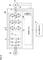
- Fig. 1 illustrates the schematic configuration and mode of use of a motor control device 20 according to a first embodiment of the present invention.
- the motor control device 20 is an apparatus (so-called servo driver) for driving a motor (three-phase motor) 55. As illustrated in the drawing, the motor control device 20 includes a power circuit 21 and a control unit 30.
- the power circuit 21 is a circuit that generates a three-phase alternating current to be supplied to the motor 55 under the control by the control unit 30 (which will be described in detail later).
- the power circuit 21 includes a rectifier circuit 22 for rectifying three-phase alternating current from a three-phase power supply 50 and a smoothing capacitor 23.
- the power circuit 21 also includes an inverter circuit 24 for converting the output voltage of the rectifier circuit 22 smoothed by the smoothing capacitor 23, into a three-phase AC voltage.
- the control unit 30 is basically a unit that controls the motor 55 by controlling the inverter circuit 24 according to an instruction from the host apparatus 10, such as a programmable logic controller (PLC).
- the control unit 30 consists of a processor (for example, CPU or microcontroller) and its peripheral circuits.
- the motor control device 20 is provided with three current sensors 25 for measuring the U-phase current value Iu, the V-phase current value Iv, and the W-phase current value Iw of the motor 55.
- the motor 55 is provided with a rotation angle sensor 56 for detecting the rotation angle ⁇ of the motor 55, and information from these sensors 25 and 56 is input to the control unit 30.
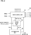
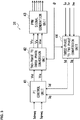
- Fig. 2 is a functional block diagram of the control unit 30, and Fig. 3 is a functional block diagram of the motor control unit 31.
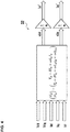
- Fig. 4 is a functional block diagram of the virtual motor unit 32, and
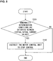
- Fig. 5 is a flowchart of a determination process performed by the determination unit 33. Note that each of the functional blocks illustrated in Figs. 2 to 4 may use a software (may be implemented as a function of a processor) or may be a hardware (such as an integrated circuit).
- control unit 30 of the motor control device 20 functions as a motor control unit 31, a virtual motor unit 32, and a determination unit 33.
- the motor control unit 31 is a functional block that controls the motor 55 by vector control based on the current command values Idreq and Iqreq, U-phase current value Iu, V-phase current value Iv, W-phase current value Iw, and rotation angle ⁇ of the motor 55.
- the virtual motor unit 32 and the determination unit 33 are functional blocks mounted on the control unit 30 so that an abnormality of the motor 55 can be detected at an early stage.
- the motor control unit 31 includes a PI control unit 41, a two-phase to three-phase conversion unit 42, a PWM signal generation unit 43, and a three-phase to two-phase conversion unit 44.
- the PI control unit 41 is a functional block that generates a voltage command value Vd by PI calculation of a current deviation between the current command value Idreq and the current value Id from the three-phase to two-phase conversion unit 44, and generates the voltage command value Vq by PI calculation of a current deviation between the current command value Iqreq and the current value Iq from the three-phase to two-phase conversion unit 44.
- the current command values Idreq and Iqreq in this embodiment are information generated in the control unit 30 based on a command (for example, speed command or position command) from the host apparatus 10 and other information (for example, the speed of the motor 55).
- the current command values Idreq and Iqreq may be information input from the host apparatus 10.
- the two-phase to three-phase conversion unit 42 is a functional block that converts the voltage command values Vd and Vq from the PI control unit 41 into three-phase AC voltage command values Vu, Vv, and Vw, using the rotation angle ⁇ of the motor 55.
- the PWM signal generation unit 43 is a functional block that generates a PWM signal for ON/OFF control of six semiconductor switches in the inverter circuit 24 based on the voltage command values Vu, Vv, and Vw from the two-phase to three-phase conversion unit 42.
- the three-phase to two-phase conversion unit 44 is a functional block that converts the current values Iu, Iv, and Iw of each phase detected by the current sensor 25 for each phase into two-phase current values Id and Iq in a rotation coordinate system based on the rotation angle ⁇ of the motor 55.
- the motor control unit 31 is a functional block that performs vector control with the above-described configuration and, upon reception of a predetermined stop instruction from the determination unit 33, stops controlling the motor 55 (inverter circuit 24) (see Fig. 2 ).
- the virtual motor unit 32 ( Fig. 2 ) is a functional block that simulates the current command values Idreq and Iqreq based on the voltage command values Vd and Vq and the like calculated by the motor control unit 31 and various preset motor parameters.
- the host apparatus 10 or another computer sets the following motor parameters in the virtual motor unit 32.
- the virtual motor unit 32 receives the voltage command values Vd and Vq and the current values Id and Iq generated during the control processing of the motor 55 by the motor control unit 31 ( Fig. 3 ) and the electrical angular velocity ⁇ (a value obtained by differentiating the electrical angle ⁇ e calculated from ⁇ ) of the motor 55.
- the virtual motor unit 32 is configured that repeats a process of calculating sId and sIq by the following equation (1) and integrating the calculated sId and sIq to obtain the simulation results Id' and Iq' of Id and Iq.
- sI d sI q V d ⁇ RI d + ⁇ L q I q V q ⁇ RI q ⁇ ⁇ L d I d ⁇ ⁇ ⁇ m
- the determination unit 33 is a functional block that performs the determination process in the procedure illustrated in Fig. 5 every time the virtual motor unit 32 calculates the simulation results Id' and Iq' of Id and Iq.
- the determination unit 33 determines whether or not abnormality determination conditions are satisfied between the virtual current value and the actual current value (Step S101).
- the virtual current value is one or both of the simulation results Id' and Iq'.
- the actual current value refers to the current command values Idreq and Iqreq, or the current values Id and Iq.
- the actual current value refers to the current command value Ixreq or the current value Ix.
- the abnormality determination conditions are conditions (a relational expression between an actual current value and a virtual current value) that is predetermined so that it can be satisfied when the motor 55 can be determined to be in an abnormal state.
- the virtual current value (Id' and/or Iq') is a theoretical value of two-phase current value flowing through the motor 55 when the motor 55 is in a normal state. Accordingly, whether or not the motor 55 is in an abnormal state can be determined by a quantity of the difference between the virtual current value and the actual current value.
- Id' and Iq' are used as virtual current values and Id and Iq are used as actual current values, for example, use of the following conditions as abnormality determination conditions makes it possible to determine whether or not the motor 55 is in an abnormal state.
- each of the thresholds and each of the allowable ranges under the various conditions described above may be predetermined through experiments, for example.
- Step S101 If the abnormality determination conditions are not satisfied (Step S101; NO), the determination unit 33 ends this determination process (the process in Fig. 5 ) without performing any process. In contrast, if the abnormality determination conditions are satisfied (Step S101; YES), the determination unit 33 instructs the motor control unit 31 to stop the control (Step S102), and ends this determination process.
- the motor control device 20 has a configuration that determines whether or not the motor 55 is in an abnormal state by comparing a current command value input to the motor control unit 31 with the current flowing though the motor 55 simulated based on the voltage command value calculated by the motor control unit 31 from the current command value.
- the motor control device has a configuration that the reference value (current command value or simulated current value) for determining whether or not the motor 55 is in an abnormal state is changed according to situations.
- Fig. 6 illustrates the schematic configuration and mode of use of a motor control device 20b according to a second embodiment of the present invention.
- the motor control device 20b is an apparatus in which the control unit 30 of the motor control device 20 is replaced with a control unit 30b.
- the control unit 30b is a unit modified from the control unit 30 so that whether or not the motor 55 is in an abnormal state is determined considering the temperature of the motor 55.
- control unit 30b has a configuration in which the virtual motor unit 32 of the control unit 30 is replaced with a virtual motor unit 32b.
- the virtual motor unit 32b is a functional block that simulates the current command values Idreq and Iqreq based on the voltage command values Vd and Vq and the like calculated by the motor control unit 31 and various preset motor parameters.
- the virtual motor unit 32b includes, as various motor parameters, information R(T) representing the resistance of the armature of each phase of the motor 55 as a function of the temperature T of the motor 55, and information Ld(T) representing the d-axis inductance of the motor 55 as a function of the temperature T.
- the temperature T of the motor 55 is input to the virtual motor unit 32b from a temperature sensor 57 attached to the motor 55.
- the virtual motor unit 32b is configured to calculate Id' and Iq' using parameter values (for example, resistance R and d-axis inductance Ld) of the motor 55 at the current temperature T (see Fig. 4 ).
- the motor control device 20b is configured to simulate the current command value in consideration of the temperature T of the motor 55; thus, this configuration does not need to determine abnormality determination conditions in consideration of the influence of the temperature T of the motor 55.
- the motor control device 20 described above it is necessary to determine abnormality determination conditions in consideration of the influence of the temperature T of the motor 55. Therefore, the motor control device 20b in which it is not necessary to determine abnormality determination conditions in consideration of the influence of the temperature T of the motor 55 can detect an abnormality of the motor 55 at an earlier stage than the motor control device 20.
- control unit 30 (motor control unit 31) may be modified to one that performs sensorless vector control or one that does not perform vector control.
- determination unit 33 may be modified to the one that sends information indicating this fact to the host apparatus 10 while sending a stop instruction or not.
Landscapes
- Engineering & Computer Science (AREA)
- Power Engineering (AREA)
- Control Of Ac Motors In General (AREA)
- Control Of Electric Motors In General (AREA)
Abstract
Description
- The present invention relates to a motor control device.
- Runaway of the motor may pose a danger to workers and damage to an equipment driven by the motor. For this reason, whether or not the motor is in a runaway state is determined by comparing a rotation speed of the motor or a drive current of the motor with a threshold (see Patent Document 1, for example).
- However, early detection of runaway of the motor has not been achieved in some cases by comparing the motor rotation speed and the like with the threshold.
- Patent document 1: Japanese Patent Laid-Open No.
H5-22977 - An object of the present invention, which was made in view of the above situation, is to provide a motor control device that can detect an abnormality of a motor at an early stage.
- To achieve the object, a motor control device that controls a motor, according to one aspect of the present invention includes: a control unit that calculates a voltage command value based on an input current command value and controls drive of the motor by using the calculated voltage command value; a virtual motor unit that simulates the value of a current flowing through the motor, based on the voltage command value calculated by the control unit and a plurality of parameters related to specifications of the motor; and a determination unit that determines whether or not the motor is in an abnormal state by comparing the current command value input to the control unit and the current value simulated by the virtual motor unit.
- In other words, the motor control device according to one aspect of the present invention has a configuration that determines whether or not the motor is in an abnormal state by comparing a current command value input to the control unit with the current value simulated based on the voltage command value calculated by a virtual motor unit from the current command value. In other words, the motor control device has a configuration that the reference value (current command value or simulated current value) for determining whether or not the motor is in an abnormal state is changed according to situations. Accordingly, the motor control device can detect an abnormality of the motor at an earlier stage than ever before.
- Various components having different specific configurations can be employed as the units (control unit, virtual motor unit, and determination unit) of the motor control device. For example, the determination unit may be a unit that compares the difference between a current command value and a current value with a threshold in order to determine whether or not the motor is in an abnormal state, or a unit that compares the ratio of the current command value to the current value with a threshold (upper/lower threshold).
- The motor control device may employ a configuration in which a d-axis current command value and a q-axis current command value as the current command value are input to the control unit, and the control unit calculates a d-axis voltage command value and a q-axis voltage command value as the voltage command value, based on the input d-axis current command value and q-axis current command value. In other words, the control unit of the motor control device may perform vector control.
- When a control unit that performs vector control is employed, the plurality of parameters may include a parameter indicating a resistance of an armature of each phase of the motor, a parameter indicating a d-axis inductance of the motor, a parameter indicating a q-axis inductance of the motor, and a parameter indicating an armature linkage flux of a permanent magnet in the motor. Further, at least one of the plurality of parameters may be information indicating temperature dependency of a physical property of the motor, and the virtual motor unit may be the one that simulates a d-axis current value and a q-axis current value of the motor, based on the d-axis voltage command value, the q-axis voltage command value, the plurality of parameters, and a temperature of the motor.
- The present invention can provide a motor control device that can detect an abnormality of a motor at an early stage.
-
-
Fig. 1 is an explanatory diagram of the schematic configuration and mode of use of a motor control device according to a first embodiment of the present invention. -
Fig. 2 is a functional block diagram of a control unit included in the motor control device according to the first embodiment. -
Fig. 3 is a functional block diagram of a motor control unit. -
Fig. 4 is a functional block diagram of a virtual motor unit. -
Fig. 5 is a flowchart of a determination process performed by a determination unit. -
Fig. 6 is an explanatory diagram of a schematic configuration and mode of use of a motor control device according to a second embodiment of the present invention. -
Fig. 7 is a functional block diagram of a control unit included in the motor control device according to the second embodiment. - An embodiment of the present invention will be described below with reference to the accompanying drawings.
-
Fig. 1 illustrates the schematic configuration and mode of use of amotor control device 20 according to a first embodiment of the present invention. - The
motor control device 20 according to this embodiment is an apparatus (so-called servo driver) for driving a motor (three-phase motor) 55. As illustrated in the drawing, themotor control device 20 includes apower circuit 21 and acontrol unit 30. - The
power circuit 21 is a circuit that generates a three-phase alternating current to be supplied to themotor 55 under the control by the control unit 30 (which will be described in detail later). Thepower circuit 21 includes arectifier circuit 22 for rectifying three-phase alternating current from a three-phase power supply 50 and asmoothing capacitor 23. Thepower circuit 21 also includes aninverter circuit 24 for converting the output voltage of therectifier circuit 22 smoothed by thesmoothing capacitor 23, into a three-phase AC voltage. - The
control unit 30 is basically a unit that controls themotor 55 by controlling theinverter circuit 24 according to an instruction from thehost apparatus 10, such as a programmable logic controller (PLC). Thecontrol unit 30 consists of a processor (for example, CPU or microcontroller) and its peripheral circuits. - As illustrated in the drawing, the
motor control device 20 is provided with threecurrent sensors 25 for measuring the U-phase current value Iu, the V-phase current value Iv, and the W-phase current value Iw of themotor 55. Themotor 55 is provided with arotation angle sensor 56 for detecting the rotation angle θ of themotor 55, and information from thesesensors control unit 30. - The function of the
control unit 30 will be described below with reference toFigs. 2 to 5 .Fig. 2 is a functional block diagram of thecontrol unit 30, andFig. 3 is a functional block diagram of themotor control unit 31.Fig. 4 is a functional block diagram of thevirtual motor unit 32, andFig. 5 is a flowchart of a determination process performed by thedetermination unit 33. Note that each of the functional blocks illustrated inFigs. 2 to 4 may use a software (may be implemented as a function of a processor) or may be a hardware (such as an integrated circuit). - As illustrated in
Fig. 2 , thecontrol unit 30 of themotor control device 20 functions as amotor control unit 31, avirtual motor unit 32, and adetermination unit 33. - The
motor control unit 31 is a functional block that controls themotor 55 by vector control based on the current command values Idreq and Iqreq, U-phase current value Iu, V-phase current value Iv, W-phase current value Iw, and rotation angle θ of themotor 55. Thevirtual motor unit 32 and thedetermination unit 33 are functional blocks mounted on thecontrol unit 30 so that an abnormality of themotor 55 can be detected at an early stage. - The functions of the
motor control unit 31, thevirtual motor unit 32, and thedetermination unit 33 will now be described in detail. - As illustrated in
Fig. 3 , themotor control unit 31 includes aPI control unit 41, a two-phase to three-phase conversion unit 42, a PWMsignal generation unit 43, and a three-phase to two-phase conversion unit 44. - The
PI control unit 41 is a functional block that generates a voltage command value Vd by PI calculation of a current deviation between the current command value Idreq and the current value Id from the three-phase to two-phase conversion unit 44, and generates the voltage command value Vq by PI calculation of a current deviation between the current command value Iqreq and the current value Iq from the three-phase to two-phase conversion unit 44. Note that the current command values Idreq and Iqreq in this embodiment are information generated in thecontrol unit 30 based on a command (for example, speed command or position command) from thehost apparatus 10 and other information (for example, the speed of the motor 55). However, the current command values Idreq and Iqreq may be information input from thehost apparatus 10. - The two-phase to three-
phase conversion unit 42 is a functional block that converts the voltage command values Vd and Vq from thePI control unit 41 into three-phase AC voltage command values Vu, Vv, and Vw, using the rotation angle θ of themotor 55. The PWMsignal generation unit 43 is a functional block that generates a PWM signal for ON/OFF control of six semiconductor switches in theinverter circuit 24 based on the voltage command values Vu, Vv, and Vw from the two-phase to three-phase conversion unit 42. - The three-phase to two-
phase conversion unit 44 is a functional block that converts the current values Iu, Iv, and Iw of each phase detected by thecurrent sensor 25 for each phase into two-phase current values Id and Iq in a rotation coordinate system based on the rotation angle θ of themotor 55. - The
motor control unit 31 is a functional block that performs vector control with the above-described configuration and, upon reception of a predetermined stop instruction from thedetermination unit 33, stops controlling the motor 55 (inverter circuit 24) (seeFig. 2 ). - The virtual motor unit 32 (
Fig. 2 ) is a functional block that simulates the current command values Idreq and Iqreq based on the voltage command values Vd and Vq and the like calculated by themotor control unit 31 and various preset motor parameters. - Before starting the actual operation of the
motor control device 20, thehost apparatus 10 or another computer sets the following motor parameters in thevirtual motor unit 32. - The resistance R[ohm] of the armature of each phase of the
motor 55 - The d-axis inductance Ld[H] and the q-axis inductance Lq[H] of the
motor 55 - The armature linkage flux ϕm [V/(rad/sec)] of the permanent magnet in the
motor 55 - During operation of the
motor control device 20, thevirtual motor unit 32 receives the voltage command values Vd and Vq and the current values Id and Iq generated during the control processing of themotor 55 by the motor control unit 31 (Fig. 3 ) and the electrical angular velocity ω (a value obtained by differentiating the electrical angle θe calculated from θ) of themotor 55. - As schematically illustrated in
Fig. 4 , thevirtual motor unit 32 is configured that repeats a process of calculating sId and sIq by the following equation (1) and integrating the calculated sId and sIq to obtain the simulation results Id' and Iq' of Id and Iq.
- Note that s in Equation (1) is a Laplace operator. Equation (1) is an equation solving the following equation (2), which is a voltage equation in the dq coordinate system of the permanent magnet synchronous motor, in terms of sId and sIq.

- The
determination unit 33 is a functional block that performs the determination process in the procedure illustrated inFig. 5 every time thevirtual motor unit 32 calculates the simulation results Id' and Iq' of Id and Iq. - In other words, when the simulation results Id' and Iq' of Id and Iq are calculated by the
virtual motor unit 32, thedetermination unit 33 determines whether or not abnormality determination conditions are satisfied between the virtual current value and the actual current value (Step S101). - Here, the virtual current value is one or both of the simulation results Id' and Iq'. When the virtual current value is Id' and Iq', the actual current value refers to the current command values Idreq and Iqreq, or the current values Id and Iq. When the virtual current value is Ix' (x = d, q), the actual current value refers to the current command value Ixreq or the current value Ix.
- The abnormality determination conditions are conditions (a relational expression between an actual current value and a virtual current value) that is predetermined so that it can be satisfied when the
motor 55 can be determined to be in an abnormal state. - In other words, the virtual current value (Id' and/or Iq') is a theoretical value of two-phase current value flowing through the
motor 55 when themotor 55 is in a normal state. Accordingly, whether or not themotor 55 is in an abnormal state can be determined by a quantity of the difference between the virtual current value and the actual current value. - To be specific, when Id' and Iq' are used as virtual current values and Id and Iq are used as actual current values, for example, use of the following conditions as abnormality determination conditions makes it possible to determine whether or not the
motor 55 is in an abnormal state. - (Id' - Id)2 + (Iq' - Iq)2 ≥ threshold
- (Id'/Id) value is out of an allowable range for Id, and (Iq'/Iq) value is out of an allowable range for Iq.
- When Ix' (x = d, q) is used as a virtual current value and Ix is used as an actual current value, for example, use of the following conditions as abnormality determination conditions makes it possible to determine whether or not the
motor 55 is in an abnormal state. - |Ix' - Ix| ≥ threshold
- (Ix'/Ix) value is out of an allowable range
- Note that each of the thresholds and each of the allowable ranges under the various conditions described above may be predetermined through experiments, for example.
- If the abnormality determination conditions are not satisfied (Step S101; NO), the
determination unit 33 ends this determination process (the process inFig. 5 ) without performing any process. In contrast, if the abnormality determination conditions are satisfied (Step S101; YES), thedetermination unit 33 instructs themotor control unit 31 to stop the control (Step S102), and ends this determination process. - As described above, the
motor control device 20 according to this embodiment has a configuration that determines whether or not themotor 55 is in an abnormal state by comparing a current command value input to themotor control unit 31 with the current flowing though themotor 55 simulated based on the voltage command value calculated by themotor control unit 31 from the current command value. In other words, the motor control device has a configuration that the reference value (current command value or simulated current value) for determining whether or not themotor 55 is in an abnormal state is changed according to situations. Hence, with the motor control device, an abnormality of the motor can be detected at an earlier stage than ever before. -
Fig. 6 illustrates the schematic configuration and mode of use of amotor control device 20b according to a second embodiment of the present invention. - The
motor control device 20b according to this embodiment is an apparatus in which thecontrol unit 30 of themotor control device 20 is replaced with acontrol unit 30b. Thecontrol unit 30b is a unit modified from thecontrol unit 30 so that whether or not themotor 55 is in an abnormal state is determined considering the temperature of themotor 55. - To be specific, as illustrated in
Fig. 7 , thecontrol unit 30b has a configuration in which thevirtual motor unit 32 of thecontrol unit 30 is replaced with avirtual motor unit 32b. - Like the
virtual motor unit 32, thevirtual motor unit 32b is a functional block that simulates the current command values Idreq and Iqreq based on the voltage command values Vd and Vq and the like calculated by themotor control unit 31 and various preset motor parameters. - However, the
virtual motor unit 32b includes, as various motor parameters, information R(T) representing the resistance of the armature of each phase of themotor 55 as a function of the temperature T of themotor 55, and information Ld(T) representing the d-axis inductance of themotor 55 as a function of the temperature T. The temperature T of themotor 55 is input to thevirtual motor unit 32b from atemperature sensor 57 attached to themotor 55. Thevirtual motor unit 32b is configured to calculate Id' and Iq' using parameter values (for example, resistance R and d-axis inductance Ld) of themotor 55 at the current temperature T (seeFig. 4 ). - As described above, the
motor control device 20b according to this embodiment is configured to simulate the current command value in consideration of the temperature T of themotor 55; thus, this configuration does not need to determine abnormality determination conditions in consideration of the influence of the temperature T of themotor 55. In themotor control device 20 described above, it is necessary to determine abnormality determination conditions in consideration of the influence of the temperature T of themotor 55. Therefore, themotor control device 20b in which it is not necessary to determine abnormality determination conditions in consideration of the influence of the temperature T of themotor 55 can detect an abnormality of themotor 55 at an earlier stage than themotor control device 20. - Various modifications can be made for the motor control devices (20 and 20b) according to the embodiments described above. For example, the control unit 30 (motor control unit 31) may be modified to one that performs sensorless vector control or one that does not perform vector control. When the abnormality determination conditions are satisfied, the
determination unit 33 may be modified to the one that sends information indicating this fact to thehost apparatus 10 while sending a stop instruction or not. - It is acceptable that not all the motor parameters set in the
virtual motor unit 32b indicate the temperature dependency, and some motor parameters set in thevirtual motor unit 32b may indicate the temperature dependency. - A motor control device (20) that controls a motor (55), comprising:
- a control unit (31) that calculates a voltage command value based on an input current command value and controls drive of the motor by using the calculated voltage command value;
- a virtual motor unit (32) that simulates the value of a current flowing through the motor, based on the voltage command value calculated by the control unit (31) and a plurality of parameters related to specifications of the motor (55); and
- a determination unit (33) that determines whether or not the motor (55) is in an abnormal state by comparing the current command value input to the control unit (31) and the current value simulated by the virtual motor unit (32).
-
- 10
- Host apparatus
- 20, 20b
- Motor control device
- 21
- Power circuit
- 22
- Rectifier circuit
- 23
- Smoothing capacitor
- 24
- Inverter circuit
- 25
- Current sensors
- 30, 30b
- Control unit
- 31
- Motor control unit
- 32, 32b
- Virtual motor unit
- 33
- Determination unit
- 41
- PI control unit
- 42
- Two-phase to three-phase conversion unit
- 43
- PWM signal generation unit
- 44
- Three-phase to two-phase conversion unit
- 50
- Three-phase power supply
- 55
- Motor
- 56
- Rotation angle sensor
- 57
- Temperature sensor
Claims (4)
- A motor control device that controls a motor, comprising:a control unit that calculates a voltage command value based on an input current command value and controls drive of the motor by using the calculated voltage command value;a virtual motor unit that simulates the value of a current flowing through the motor, based on the voltage command value calculated by the control unit and a plurality of parameters related to specifications of the motor; anda determination unit that determines whether or not the motor is in an abnormal state by comparing the current command value input to the control unit and the current value simulated by the virtual motor unit.
- The motor control device according to Claim 1, wherein
a d-axis current command value and a q-axis current command value as the current command value are input to the control unit, and
the control unit calculates a d-axis voltage command value and a q-axis voltage command value as the voltage command value, based on the input d-axis current command value and q-axis current command value. - The motor control device according to Claim 2, wherein the plurality of parameters include a parameter indicating a resistance of an armature of each phase of the motor, a parameter indicating a d-axis inductance of the motor, a parameter indicating a q-axis inductance of the motor, and a parameter indicating an armature linkage flux of a permanent magnet in the motor.
- The motor control device according to Claim 3, wherein
at least one of the plurality of parameters is information indicating temperature dependency of a physical property of the motor, and
the virtual motor unit simulates a d-axis current value and a q-axis current value of the motor, based on the d-axis voltage command value, the q-axis voltage command value, the plurality of parameters, and a temperature of the motor.
Applications Claiming Priority (2)
| Application Number | Priority Date | Filing Date | Title |
|---|---|---|---|
| JP2018063668A JP2019176649A (en) | 2018-03-29 | 2018-03-29 | Motor controller |
| PCT/JP2019/006356 WO2019187815A1 (en) | 2018-03-29 | 2019-02-20 | Motor control device |
Publications (2)
| Publication Number | Publication Date |
|---|---|
| EP3780383A1 true EP3780383A1 (en) | 2021-02-17 |
| EP3780383A4 EP3780383A4 (en) | 2021-12-01 |
Family
ID=68059811
Family Applications (1)
| Application Number | Title | Priority Date | Filing Date |
|---|---|---|---|
| EP19778380.6A Withdrawn EP3780383A4 (en) | 2018-03-29 | 2019-02-20 | ENGINE CONTROL DEVICE |
Country Status (5)
| Country | Link |
|---|---|
| US (1) | US11133769B2 (en) |
| EP (1) | EP3780383A4 (en) |
| JP (1) | JP2019176649A (en) |
| CN (1) | CN111034030A (en) |
| WO (1) | WO2019187815A1 (en) |
Families Citing this family (3)
| Publication number | Priority date | Publication date | Assignee | Title |
|---|---|---|---|---|
| CN108599651B (en) * | 2018-05-15 | 2020-07-03 | 华中科技大学 | Virtual voltage injection-based speed sensorless driving control method for induction motor |
| KR102893003B1 (en) | 2019-09-16 | 2025-11-27 | 루머스 리미티드 | Compact projector for head-mounted displays |
| KR102488028B1 (en) * | 2020-10-29 | 2023-01-13 | 경북대학교 산학협력단 | Inter-turn short fault detecting apparatus of induction motor and method thereof |
Family Cites Families (13)
| Publication number | Priority date | Publication date | Assignee | Title |
|---|---|---|---|---|
| JPS5321722A (en) * | 1976-08-12 | 1978-02-28 | Toshiba Corp | Method and apparatus for directly controlling motor |
| JPS5980175A (en) * | 1982-10-25 | 1984-05-09 | Toshiba Corp | Speed controller for motor |
| JP3058360B2 (en) | 1991-07-12 | 2000-07-04 | 株式会社安川電機 | Servo motor runaway detection / prevention method |
| JP2797882B2 (en) * | 1993-03-12 | 1998-09-17 | 三菱電機株式会社 | Servo motor control device |
| US6900607B2 (en) * | 2001-08-17 | 2005-05-31 | Delphi Technologies, Inc. | Combined feedforward and feedback parameter estimation for electric machines |
| JP5924290B2 (en) * | 2012-04-20 | 2016-05-25 | 三菱電機株式会社 | Motor control device |
| JP5301025B1 (en) * | 2012-12-25 | 2013-09-25 | ディエスピーテクノロジ株式会社 | Motor control device and motor control method |
| CN103701394B (en) * | 2013-12-30 | 2016-06-08 | 哈尔滨工业大学 | A kind of online diagnostic method of the open-circuit fault of power tubes of inverter based on the magnitude of current |
| CN103997274B (en) * | 2014-05-30 | 2016-05-18 | 清华大学 | Model reference adaptive systematic parameter automatic setting method based on one dimension fuzzy control |
| CN105634310B (en) * | 2014-11-06 | 2018-09-04 | 台达电子工业股份有限公司 | Control signal generating system, inverter control device and related control circuit thereof |
| WO2016143481A1 (en) * | 2015-03-10 | 2016-09-15 | 株式会社明電舎 | Synchronization control device for power converter |
| EP3160037A1 (en) * | 2015-10-20 | 2017-04-26 | ABB Schweiz AG | Method for identifying the discrete instantaneous angular speed of an electromechanical system |
| CN105490605A (en) * | 2015-12-16 | 2016-04-13 | 上海新时达电气股份有限公司 | Online adjustment method for prediction control model parameters of induction motor |
-
2018
- 2018-03-29 JP JP2018063668A patent/JP2019176649A/en active Pending
-
2019
- 2019-02-20 EP EP19778380.6A patent/EP3780383A4/en not_active Withdrawn
- 2019-02-20 US US16/643,611 patent/US11133769B2/en active Active
- 2019-02-20 WO PCT/JP2019/006356 patent/WO2019187815A1/en not_active Ceased
- 2019-02-20 CN CN201980003974.6A patent/CN111034030A/en active Pending
Also Published As
| Publication number | Publication date |
|---|---|
| JP2019176649A (en) | 2019-10-10 |
| US11133769B2 (en) | 2021-09-28 |
| US20200212835A1 (en) | 2020-07-02 |
| CN111034030A (en) | 2020-04-17 |
| EP3780383A4 (en) | 2021-12-01 |
| WO2019187815A1 (en) | 2019-10-03 |
Similar Documents
| Publication | Publication Date | Title |
|---|---|---|
| JP5397023B2 (en) | AC motor control device | |
| JP5910460B2 (en) | Disconnection detector | |
| JP3218954B2 (en) | Abnormality detection device for AC motor control circuit | |
| JP5402403B2 (en) | Electric motor control system | |
| JP4860012B2 (en) | Electric vehicle power converter | |
| JP6183291B2 (en) | Control device for synchronous motor | |
| JP5664928B2 (en) | Rotating electrical machine control device | |
| JP2003348900A (en) | Motor abnormality detection device and electric power steering control device | |
| JP6338705B2 (en) | Motor drive control device | |
| US11133769B2 (en) | Motor control device | |
| US9184687B2 (en) | Motor control apparatus and motor control method | |
| CN105850029A (en) | Power conversion device | |
| CN108802611B (en) | Abnormality diagnosis device and abnormality diagnosis method | |
| US10389290B2 (en) | Motor control apparatus | |
| CN114814575A (en) | Motor stall detection method, device, external variable frequency drive and medium | |
| JP5959349B2 (en) | Electric vehicle control device and vehicle drive system | |
| JP6591794B2 (en) | Induction machine power converter, second-order time constant measuring method and speed control method | |
| JP7153879B2 (en) | Electric tool | |
| CN113169701B (en) | A method and apparatus for a fail-safe speed monitoring process | |
| JP2004032848A (en) | Motor controller and motor-driven power steering system | |
| EP4383554A1 (en) | Motor control device | |
| JP6588410B2 (en) | Electric motor drive | |
| WO2021111856A1 (en) | Power conversion device, diagonosis device, and diagnosis method | |
| JP6082316B2 (en) | Induction motor controller | |
| JP6087109B2 (en) | AC motor control apparatus and current detector soundness confirmation method |
Legal Events
| Date | Code | Title | Description |
|---|---|---|---|
| STAA | Information on the status of an ep patent application or granted ep patent |
Free format text: STATUS: THE INTERNATIONAL PUBLICATION HAS BEEN MADE |
|
| PUAI | Public reference made under article 153(3) epc to a published international application that has entered the european phase |
Free format text: ORIGINAL CODE: 0009012 |
|
| STAA | Information on the status of an ep patent application or granted ep patent |
Free format text: STATUS: REQUEST FOR EXAMINATION WAS MADE |
|
| 17P | Request for examination filed |
Effective date: 20200302 |
|
| AK | Designated contracting states |
Kind code of ref document: A1 Designated state(s): AL AT BE BG CH CY CZ DE DK EE ES FI FR GB GR HR HU IE IS IT LI LT LU LV MC MK MT NL NO PL PT RO RS SE SI SK SM TR |
|
| AX | Request for extension of the european patent |
Extension state: BA ME |
|
| DAV | Request for validation of the european patent (deleted) | ||
| DAX | Request for extension of the european patent (deleted) | ||
| A4 | Supplementary search report drawn up and despatched |
Effective date: 20211102 |
|
| RIC1 | Information provided on ipc code assigned before grant |
Ipc: H02P 21/13 20060101ALI20211026BHEP Ipc: H02P 21/06 20160101ALI20211026BHEP Ipc: H02P 29/024 20160101AFI20211026BHEP |
|
| STAA | Information on the status of an ep patent application or granted ep patent |
Free format text: STATUS: EXAMINATION IS IN PROGRESS |
|
| 17Q | First examination report despatched |
Effective date: 20230428 |
|
| STAA | Information on the status of an ep patent application or granted ep patent |
Free format text: STATUS: THE APPLICATION IS DEEMED TO BE WITHDRAWN |
|
| 18D | Application deemed to be withdrawn |
Effective date: 20241126 |