EP3780342A1 - Stator, electric motor, electric vacuum cleaner, and hand drying device - Google Patents
Stator, electric motor, electric vacuum cleaner, and hand drying device Download PDFInfo
- Publication number
- EP3780342A1 EP3780342A1 EP18911634.6A EP18911634A EP3780342A1 EP 3780342 A1 EP3780342 A1 EP 3780342A1 EP 18911634 A EP18911634 A EP 18911634A EP 3780342 A1 EP3780342 A1 EP 3780342A1
- Authority
- EP
- European Patent Office
- Prior art keywords
- electric motor
- stator
- tooth
- rotor
- winding
- Prior art date
- Legal status (The legal status is an assumption and is not a legal conclusion. Google has not performed a legal analysis and makes no representation as to the accuracy of the status listed.)
- Withdrawn
Links
Images






Classifications
-
- H—ELECTRICITY
- H02—GENERATION; CONVERSION OR DISTRIBUTION OF ELECTRIC POWER
- H02K—DYNAMO-ELECTRIC MACHINES
- H02K1/00—Details of the magnetic circuit
- H02K1/06—Details of the magnetic circuit characterised by the shape, form or construction
- H02K1/12—Stationary parts of the magnetic circuit
- H02K1/16—Stator cores with slots for windings
- H02K1/165—Shape, form or location of the slots
-
- H—ELECTRICITY
- H02—GENERATION; CONVERSION OR DISTRIBUTION OF ELECTRIC POWER
- H02K—DYNAMO-ELECTRIC MACHINES
- H02K1/00—Details of the magnetic circuit
- H02K1/06—Details of the magnetic circuit characterised by the shape, form or construction
- H02K1/12—Stationary parts of the magnetic circuit
- H02K1/14—Stator cores with salient poles
- H02K1/146—Stator cores with salient poles consisting of a generally annular yoke with salient poles
- H02K1/148—Sectional cores
-
- A—HUMAN NECESSITIES
- A47—FURNITURE; DOMESTIC ARTICLES OR APPLIANCES; COFFEE MILLS; SPICE MILLS; SUCTION CLEANERS IN GENERAL
- A47K—SANITARY EQUIPMENT; ACCESSORIES THEREFOR, e.g. TOILET ACCESSORIES
- A47K10/00—Body-drying implements; Toilet paper; Holders therefor
- A47K10/48—Drying by means of hot air
-
- A—HUMAN NECESSITIES
- A47—FURNITURE; DOMESTIC ARTICLES OR APPLIANCES; COFFEE MILLS; SPICE MILLS; SUCTION CLEANERS IN GENERAL
- A47L—DOMESTIC WASHING OR CLEANING; SUCTION CLEANERS IN GENERAL
- A47L9/00—Details or accessories of suction cleaners, e.g. mechanical means for controlling the suction or for effecting pulsating action; Storing devices specially adapted to suction cleaners or parts thereof; Carrying-vehicles specially adapted for suction cleaners
- A47L9/28—Installation of the electric equipment, e.g. adaptation or attachment to the suction cleaner; Controlling suction cleaners by electric means
- A47L9/2836—Installation of the electric equipment, e.g. adaptation or attachment to the suction cleaner; Controlling suction cleaners by electric means characterised by the parts which are controlled
- A47L9/2842—Suction motors or blowers
-
- H—ELECTRICITY
- H02—GENERATION; CONVERSION OR DISTRIBUTION OF ELECTRIC POWER
- H02K—DYNAMO-ELECTRIC MACHINES
- H02K11/00—Structural association of dynamo-electric machines with electric components or with devices for shielding, monitoring or protection
- H02K11/20—Structural association of dynamo-electric machines with electric components or with devices for shielding, monitoring or protection for measuring, monitoring, testing, protecting or switching
- H02K11/21—Devices for sensing speed or position, or actuated thereby
- H02K11/215—Magnetic effect devices, e.g. Hall-effect or magneto-resistive elements
-
- H—ELECTRICITY
- H02—GENERATION; CONVERSION OR DISTRIBUTION OF ELECTRIC POWER
- H02K—DYNAMO-ELECTRIC MACHINES
- H02K3/00—Details of windings
- H02K3/04—Windings characterised by the conductor shape, form or construction, e.g. with bar conductors
- H02K3/12—Windings characterised by the conductor shape, form or construction, e.g. with bar conductors arranged in slots
-
- H—ELECTRICITY
- H02—GENERATION; CONVERSION OR DISTRIBUTION OF ELECTRIC POWER
- H02K—DYNAMO-ELECTRIC MACHINES
- H02K3/00—Details of windings
- H02K3/04—Windings characterised by the conductor shape, form or construction, e.g. with bar conductors
- H02K3/28—Layout of windings or of connections between windings
-
- H—ELECTRICITY
- H02—GENERATION; CONVERSION OR DISTRIBUTION OF ELECTRIC POWER
- H02K—DYNAMO-ELECTRIC MACHINES
- H02K3/00—Details of windings
- H02K3/46—Fastening of windings on the stator or rotor structure
- H02K3/48—Fastening of windings on the stator or rotor structure in slots
-
- A—HUMAN NECESSITIES
- A47—FURNITURE; DOMESTIC ARTICLES OR APPLIANCES; COFFEE MILLS; SPICE MILLS; SUCTION CLEANERS IN GENERAL
- A47L—DOMESTIC WASHING OR CLEANING; SUCTION CLEANERS IN GENERAL
- A47L5/00—Structural features of suction cleaners
- A47L5/12—Structural features of suction cleaners with power-driven air-pumps or air-compressors, e.g. driven by motor vehicle engine vacuum
- A47L5/22—Structural features of suction cleaners with power-driven air-pumps or air-compressors, e.g. driven by motor vehicle engine vacuum with rotary fans
- A47L5/24—Hand-supported suction cleaners
-
- H—ELECTRICITY
- H02—GENERATION; CONVERSION OR DISTRIBUTION OF ELECTRIC POWER
- H02K—DYNAMO-ELECTRIC MACHINES
- H02K21/00—Synchronous motors having permanent magnets; Synchronous generators having permanent magnets
- H02K21/12—Synchronous motors having permanent magnets; Synchronous generators having permanent magnets with stationary armatures and rotating magnets
- H02K21/14—Synchronous motors having permanent magnets; Synchronous generators having permanent magnets with stationary armatures and rotating magnets with magnets rotating within the armatures
- H02K21/16—Synchronous motors having permanent magnets; Synchronous generators having permanent magnets with stationary armatures and rotating magnets with magnets rotating within the armatures having annular armature cores with salient poles
-
- H—ELECTRICITY
- H02—GENERATION; CONVERSION OR DISTRIBUTION OF ELECTRIC POWER
- H02K—DYNAMO-ELECTRIC MACHINES
- H02K2201/00—Specific aspects not provided for in the other groups of this subclass relating to the magnetic circuits
- H02K2201/03—Machines characterised by aspects of the air-gap between rotor and stator
-
- H—ELECTRICITY
- H02—GENERATION; CONVERSION OR DISTRIBUTION OF ELECTRIC POWER
- H02K—DYNAMO-ELECTRIC MACHINES
- H02K2203/00—Specific aspects not provided for in the other groups of this subclass relating to the windings
- H02K2203/12—Machines characterised by the bobbins for supporting the windings
-
- H—ELECTRICITY
- H02—GENERATION; CONVERSION OR DISTRIBUTION OF ELECTRIC POWER
- H02K—DYNAMO-ELECTRIC MACHINES
- H02K29/00—Motors or generators having non-mechanical commutating devices, e.g. discharge tubes or semiconductor devices
- H02K29/03—Motors or generators having non-mechanical commutating devices, e.g. discharge tubes or semiconductor devices with a magnetic circuit specially adapted for avoiding torque ripples or self-starting problems
Definitions
- the present invention relates to a stator of an electric motor.
- a stator core formed by a plurality of split cores is generally used.
- the density of a stator coil or coils can be increased, and the motor efficiency thus improves.
- a stator core is divided into 12 core constituent bodies, and the electric motor therefore includes 12 teeth.
- Patent Reference 1 Japanese Patent Application Publication No. 2005-117844
- a stator according to the present invention is provided as a stator disposed outside a rotor of an electric motor, the stator including four split cores arranged in a circumferential direction about a rotation axis of the rotor, the split cores each including a tooth, and a yoke including a pair of joint parts each having a length from the tooth toward an outer side in a radial direction of the stator, wherein in a plane perpendicular to the rotation axis of the rotor, a shape of an end of the tooth in the radial direction is asymmetrical, and an angle ⁇ 1 (degrees) formed by a side surface of the tooth and a side surface of the yoke on an inner side in the radial direction of the stator satisfies 90 degrees ⁇ ⁇ 1 ⁇ 180 degrees.
- the present invention can provide a stator having high controllability and facilitating winding of a winding on the stator.
- Each drawing illustrates a structure of an electric motor 1 and structures of components of the electric motor 1 in a plane perpendicular to a rotation axis Ax of a rotor 3.
- FIG. 1 is a plan view schematically illustrating a structure of the electric motor 1 according to Embodiment 1 of the present invention.
- An arrow D1 indicates the circumferential directions of a stator 2 and stator cores 21 about the rotation axis Ax of the rotor 3.
- the arrow D1 also indicates the circumferential direction of the rotor 3 about the rotation axis Ax of the rotor 3.
- the direction indicated by the arrow D1 will also be simply referred to as the "circumferential direction" hereinafter.
- insulators 22 are illustrated in the shape of a cross-section in a plane perpendicular to the rotation axis Ax of the rotor 3.
- FIG. 2 is a plan view schematically illustrating a structure of a split core 20.
- the insulator 22 and a winding 26 are illustrated in the shape of a cross-section perpendicular to the rotation axis Ax of the rotor 3.
- the insulator 22 and the winding 26 are illustrated in the shape of a cross-section perpendicular to the rotation axis Ax of the rotor 3.
- An arrow D2 indicates the radial directions of the stator 2, the stator cores 21, and the rotor 3 (to be also simply referred to as the "radial direction” hereinafter).
- An arrow D21 indicates the "inner side in the radial direction”
- an arrow D22 indicates the "outer side in the radial direction.”
- FIG. 3 is a plan view schematically illustrating a structure of the stator core 21.
- FIGS. 4 to 6 are plan views schematically illustrating the structure of the split core 20.
- the electric motor 1 includes the stator 2 and the rotor 3.
- the electric motor 1 is designed as, for example, a permanent magnet synchronous motor.
- the electric motor 1 is driven by, for example, a single-phase inverter.
- the number of switching operations can be reduced, and the switching loss in high-speed rotation can be reduced, compared, for example, to driving by a three-phase inverter.
- the electrical frequency becomes high and the number of switching operations increase, the advantage of using a single-phase inverter is obtained especially in high-speed rotation.
- the stator 2 includes at least one stator core 21, at least one insulator 22, a plurality of split faces 23, a position sensor 4, and at least one winding 26.
- the stator 2 is disposed outside the rotor 3 through an air gap.
- the rotor 3 is disposed inside the stator 2 through the air gap.
- the insulators 22 insulate the stator cores 21.
- the windings 26 are wound on the stator cores 21 and, more specifically, around teeth 21b through the insulators 22. Accordingly, at least one winding 26 is wound around the insulator 22.
- the windings 26 are wound around the teeth 21b by, for example, concentrated winding.
- the stator 2 (more specifically, the plurality of stator cores 21) includes a plurality of yokes 21a and a plurality of teeth 21b.
- the stator cores 21 are formed of, for example, a plurality of amorphous metals or a plurality of electrical steel sheets that are laminated.
- the insulators 22 are disposed in slots 27 implemented as regions each formed between two teeth 21b adjacent to each other. More specifically, the insulators 22 are fixed to the side surfaces of the stator cores 21.
- the insulators 22 are made of, for example, an insulating resin.
- Outer peripheral surfaces 24 of the stator cores 21 are formed in arc shapes. More specifically, the outer peripheral surfaces 24 are the outer peripheral surfaces of the yokes 21a formed outermost in the radial direction.
- the rotor 3 includes a plurality of permanent magnets and form a plurality of magnetic poles. In this Embodiment, the rotor 3 has four magnetic poles.
- the position sensor 4 includes, for example, a Hall element to detect a magnetic field emanating from the rotor 3. Hence, the position sensor 4 can detect a magnetic field emanating from the rotor 3.
- the position sensor 4 is disposed adjacent to the teeth 21b in the circumferential direction. More specifically, the position sensor 4 is fixed by at least one insulator 22 between two teeth 21b adjacent to each other.
- the position sensor 4 is mounted in, for example, a recess formed in the insulator 22. This makes it possible to downsize the electric motor 1.
- the position sensor 4 may even be fixed by two insulators 22 adjacent to each other.
- Control of the electric motor 1 can be facilitated by using the position sensor 4 to detect a magnetic field emanating from the rotor 3, and further detecting the rotation position (more specifically, the phase) of the rotor 3. Moreover, since the position sensor 4 is fixed between the two teeth 21b, it is possible to prevent the electric motor 1 from getting larger and to downsize the electric motor 1.
- the stator 2 includes a plurality of split cores 20 arranged in the circumferential direction, as illustrated in FIG. 1 .
- the stator 2 is formed by four split cores 20 arranged in the circumferential direction.
- the stator 2 is divided into parts equal in number to the teeth 21b. In other words, the stator 2 is divided into four split cores 20. Accordingly, the stator 2 includes four yokes 21a and four teeth 21b.
- Each split core 20 includes the stator core 21 and the insulator 22.
- Each stator core 21 includes one yoke 21a, one tooth 21b extending in the radial direction from the yoke 21a, and two split faces 23.
- Each split face 23 is formed at an end of the yoke 21a of each stator core 21 in the circumferential direction.
- Split end portions 23a illustrated in FIG. 3 are the inner ends of the respective split faces 23 in the radial direction.
- the insulator 22 is mounted on the stator core 21, and at least one winding 26 is wound around the insulator 22. Accordingly, the insulator 22 and at least one winding 26 also serve as components of the split core 20.
- the yoke 21a includes at least one pair of back yokes 211 and at least one pair of joint parts 212.
- Each joint part 212 has a length from the tooth 21b toward the outer side in the radial direction
- each back yoke 211 has a length from the corresponding joint part 212 toward the inner side in the radial direction. More specifically, each back yoke 211 extends in the circumferential direction.
- the tooth 21b extends inwards in the radial direction from the yoke 21a.
- the tooth 21b and the pair of joint parts 212 form a Y shape.
- the surface area of the stator core 21, more specifically, the surface area of the yoke 21a can be increased, heat generated by the electric motor 1 can be efficiently dissipated outside the electric motor 1.
- Each joint part 212 and the corresponding back yoke 211 may even be formed in a straight line. In this case, in the plane perpendicular to the rotation axis Ax of the rotor 3, the yoke 21a and the tooth 21b form a Y shape as a whole.
- the yoke 21a may even include no back yokes 211, and may include only the pair of joint parts 212. In this case as well, in the plane perpendicular to the rotation axis Ax of the rotor 3, the yoke 21a and the tooth 21b form a Y shape as a whole.
- the angle ⁇ 1 (degrees) formed by each side surface 21c of the tooth 21b and a corresponding side surface 21d of the yoke 21a on the inner side in the radial direction satisfies 90 degrees ⁇ ⁇ 1 ⁇ 180 degrees, as illustrated in FIG. 3 .
- the side surfaces 21d of the yoke 21a also serve more specifically as the side surfaces of the joint parts 212.
- the angle ⁇ 1 (degrees) formed by each side surface 21c of the tooth 21b and the side surface 21d of the corresponding joint part 212 on the inner side in the radial direction satisfies 90 degrees ⁇ ⁇ 1 ⁇ 180 degrees.
- the side surfaces 21c of the tooth 21b are surfaces extending in the radial direction, that is, surfaces on the both sides of the tooth 21b in a direction perpendicular to the radial direction.
- the side surfaces 21d of the yoke 21a are adjacent to the side surfaces 21c of the tooth 21b.
- the shape of an end 213 of the tooth 21b in the radial direction is asymmetrical.
- the magnetic pole center of the rotor 3 is located on the right with respect to a straight line A1 illustrated in FIG. 3 (that is, on the downstream side in the direction in which the rotor 3 rotates) while the rotor 3 is stopped, due to the differences in size of the air gap between the stator 2 and the rotor 3.
- supplying a magnetic field from the stator 2 to the rotor 3 in starting the electric motor 1 makes it possible to set the direction in which the rotor 3 rotates to one direction (more specifically, from the upstream side to the downstream side). If the shape of the end 213 of the tooth 21b is symmetrical in the circumferential direction, and the air gap is uniform in the circumferential direction, the magnetic pole center of the rotor 3 is located on the straight line A1 while the rotor 3 is stopped. In this case, the rotor 3 may rotate in the reverse direction when a magnetic field is supplied from the stator 2 to the rotor 3.
- the shape of the end 213 differs between the left and right sides of the end 213 with respect to the straight line A1 passing through the center of the stator core 21.
- the shape of the end 213 differs between the upstream and downstream sides in the direction in which the rotor 3 rotates.
- the upstream side in the direction in which the rotor 3 rotates corresponds to the left side with respect to the straight line A1
- the downstream side in this direction corresponds to the right side with respect to the straight line A1.
- the end 213 on the upstream side in the direction in which the rotor 3 rotates extends linearly.
- the end 213 on the downstream side in the direction in which the rotor 3 rotates is curved in an arc shape along the outer peripheral surface of the rotor 3. Accordingly, the air gap between the stator 2 and the rotor 3 on the upstream side in the direction in which the rotor 3 rotates is larger than that on the downstream side in this direction.
- the gap between the stator 2 and the rotor 3 is larger on one side (that is, the upstream side) in the circumferential direction than on the other side (that is, the downstream side) in this direction.
- the thickness t3 of the end portion of the tooth 21b on the downstream side is larger than the thickness t4 of the end portion of the tooth 21b on the upstream side.
- the end portion of the tooth 21b extends in the circumferential direction.
- the thickness t3 is the thickness, in the radial direction, of the end portion of the tooth 21b on the downstream end.
- the thickness t4 is the thickness, in the radial direction, of the end portion of the tooth 21b on the upstream end.
- the magnetic flux density increases at an end of the downstream side of the end portion of the tooth, and the iron loss increases at the end of the downstream side.
- the thickness t3 of the end portion of the tooth 21b on the downstream side is larger than the thickness t4 of the end portion of the tooth 21b on the upstream side, an increase in magnetic flux density on the downstream side of the end portion of the tooth 21b can be kept down and an increase in iron loss can be kept down.
- the shape of the end 213, however, is not limited to this Embodiment as long as the shape of the end 213 is asymmetrical.
- the insulator 22 includes a pair of first portions 221 and a pair of second portions 222, as illustrated in FIG. 4 .
- the pair of first portions 221 may be separated from each other, or integrated with each other.
- the pair of second portions 222 may also be separated from each other, or integrated with each other.
- the first portions 221 are disposed on both sides of the tooth 21b in a plane perpendicular to the rotation axis Ax of the rotor 3, as illustrated in FIG. 4 .
- the first portions 221 face the side surfaces 21c of the tooth 21b.
- the first portions 221 extend in a direction perpendicular to the radial direction in the plane perpendicular to the rotation axis Ax of the rotor 3.
- the first portions 221 include side surfaces 22d.
- the side surfaces 22d extend in the direction perpendicular to the radial direction in the plane perpendicular to the rotation axis Ax of the rotor 3.
- the second portions 222 face the tooth 21b and the joint parts 212. More specifically, the second portions 222 face the side surfaces 21d of the yoke 21a and the side surfaces 21c of the tooth 21b. The second portions 222 insulate the side surfaces 21d of the yoke 21a and the side surfaces 21c of the tooth 21b. Therefore, the insulator 22 insulates the yoke 21a and the tooth 21b. The second portions 222 may face the back yokes 211.
- the angle ⁇ 2 (degrees) formed by each side surface 22a of the insulator 22 fixed to the tooth 21b and a corresponding side surface 22b of the insulator 22 fixed to the yoke 21a satisfies 90 degrees ⁇ ⁇ 2 ⁇ 180 degrees, as illustrated in FIG. 5 .
- the side surfaces 22b are adjacent to the side surfaces 22a.
- the split end portions 23a are located outside a straight line L1 in the radial direction, as illustrated in FIG. 6 .
- the straight line L1 serves as the boundary between the yoke 21a and the tooth 21b.
- the straight line L1 serves as the boundary between each of the side surfaces 21d of the yoke 21a and each of the side surfaces 21c of the tooth 21b.
- end portions 22c that are the ends of the insulator 22 in the circumferential direction are located outside the straight line L1 in the radial direction. This makes it possible to obtain an advantage that winding of the winding 26 is facilitated and to increase the density of a stator coil.
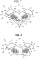
- FIG. 7 is a diagram illustrating a relationship between the shape of the end 213 of the tooth 21b and the shape of the insulator 22 (more specifically, the first portions 221).
- An angle ⁇ 1 represents the angle formed by two straight lines L2 passing through the rotation axis Ax and both ends E1 of the end 213 of the tooth 21b in a direction perpendicular to the radial direction in a plane perpendicular to the rotation axis Ax of the rotor 3.
- An angle ⁇ 2 represents the angle formed by two straight lines L3 passing through the rotation axis Ax and both ends E2 of the pair of first portions 221 in the direction perpendicular to the radial direction in the plane perpendicular to the rotation axis Ax of the rotor 3.
- the relationship between the angles ⁇ 1 and ⁇ 2 is given by ⁇ 2 > ⁇ 1.
- the ends E2 are the ends of the side surfaces 22d in the direction perpendicular to the radial direction, in the plane perpendicular to the rotation axis Ax of the rotor 3.
- the insulator 22 (more specifically, the first portions 221) extends in a direction perpendicular to the radial direction. More specifically, the insulator 22 (more specifically, the first portions 221) can be formed to be longer in the direction perpendicular to the radial direction than the end 213 of the tooth 21b. In other words, the insulator 22 (more specifically, the first portions 221) can be formed so that the side surfaces 22d of the first portions 221 are longer than the end 213 of the tooth 21b in the direction perpendicular to the radial direction. This makes it possible to wind the winding 26 around the insulator 22 with a larger number of turns and to support the winding 26 by the side surfaces 22d.
- FIGS. 8 and 9 are diagrams each illustrating a relationship between the thickness of the first portion 221 of the insulator 22 and the thickness of the second portion 222 of the insulator 22.
- the thickness t2 of the first portion 221 of the insulator 22 is the maximum thickness of the first portion 221 in the direction along a straight line L5, in a plane perpendicular to the rotation axis Ax of the rotor 3, as illustrated in FIG. 9 .
- the straight line L5 is a straight line passing through a contact point C4 and a center C3 of the winding 26, in the plane perpendicular to the rotation axis Ax of the rotor 3, as illustrated in FIG. 9 .
- the center C3 of the winding 26 is the center of the winding 26 abutting against the first portion 221, in the plane perpendicular to the rotation axis Ax of the rotor 3.
- the contact point C4 is the contact point between the first portion 221 and the winding 26 abutting against the first portion 221, in the plane perpendicular to the rotation axis Ax of the rotor 3.
- the thickness t1 of the second portion 222 of the insulator 22 is the minimum thickness of the second portion 222 in the direction along a straight line L4, in a plane perpendicular to the rotation axis Ax of the rotor 3, as illustrated in FIG. 9 .
- the straight line L4 is a straight line passing through a contact point C2 and a center C1 of the winding 26, in the plane perpendicular to the rotation axis Ax of the rotor 3, as illustrated in FIG. 9 .
- the center C1 of the winding 26 is the center of the winding 26 abutting against the second portion 222, in the plane perpendicular to the rotation axis Ax of the rotor 3.
- the contact point C2 is the contact point between the second portion 222 and the winding 26 abutting against the second portion 222, in the plane perpendicular to the rotation axis Ax of the rotor 3.
- the relationship between the maximum thickness t2 of the first portion 221 and the minimum thickness t1 of the second portion 222 satisfies t2 > t1.
- FIG. 10 is a diagram illustrating a stress F occurring on the insulator 22 due to winding of the winding 26.
- the rigidity of portions of the insulator 22 that are not supported by the stator core 21, that is, the first portions 221 of the insulator 22 can be maintained similarly to the second portions 222 of the insulator 22.
- the rigidity against the stress F occurring on the first portions 221 due to winding of the winding 26 can be enhanced. This makes it possible to prevent deformation of the first portions 221 of the insulator 22.
- FIGS. 8 to 10 each illustrate only the relationship between the maximum thickness t2 and the minimum thickness t1 of the second portion 222 in the insulator 22 disposed on the right side of the tooth 21b
- the insulator 22 disposed on the left side of the tooth 21b may even hold the relationship between the maximum thickness t2 and the minimum thickness t1 of the second portion 222 in the insulator 22 lying on the right side, that is, t2 > t1.
- the insulator 22 lying on the left side also has the effects of the above-mentioned insulator 22 lying on the right side.
- FIG. 11 is a plan view schematically illustrating a structure of the electric motor 1 including the stator 2 fixed by caulking.
- FIG. 12 is a plan view schematically illustrating a structure of the split core 20 including the stator core 21 fixed by caulking.
- Caulked parts 25 illustrated in FIGS. 11 and 12 are portions fixed by caulking.
- a plurality of amorphous metals or a plurality of electrical steel sheets forming the stator cores 21 may be fixed by caulking in the caulked parts 25, as illustrated in FIGS. 11 and 12 .
- structures other than the caulked parts 25 are the same as those of the electric motor 1 and the split core 20, respectively, illustrated in FIGS. 1 to 10 .
- caulking makes it possible to stabilize the shapes of the stator cores 21 and, in turn, to stabilize the shapes of the split faces 23. Accordingly, when, for example, the frame 5 ( FIG. 13 ) is fitted to the electric motor 1 by shrink fitting, the split cores 20 can be prevented from coming apart at the split faces 23.
- FIG. 13 is a plan view illustrating a structure of the electric motor 1 further including the frame 5.
- the frame 5 is illustrated in the shape of a cross-section in a plane perpendicular to the rotation axis Ax of the rotor 3.
- the frame 5 covers the stator 2 of the electric motor 1.
- the frame 5 has, for example, a cylindrical shape.
- Contact portions in contact with the inner peripheral surface of the frame 5 are outer peripheral surfaces 24 of the yokes 21a (more specifically, the back yokes 211) formed in arc shapes.
- the outer peripheral surfaces 24 are formed in arc shapes, and are therefore in contact with the frame 5 by surface contact. This makes it possible to obtain an advantage that fixing of the stator 2 is stabilized in the frame 5 and the shape of the stator 2 can easily be maintained.
- Spaces 6 exist between the yokes 21a and the frame 5. More specifically, the spaces 6 exist between the frame 5 and the joint parts 212 of the yokes 21a. This makes it possible to easily dissipate heat generated by the electric motor 1 from the spaces 6 to the exterior of the electric motor 1. As a result, a rise in temperature of the electric motor 1 can be reduced, and the efficiency of the electric motor 1 can thus be improved.
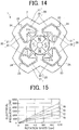
- FIG. 14 is a plan view illustrating another example of the electric motor 1.
- the electric motor 1 illustrated in FIG. 14 includes no position sensor 4.
- the structure of the above-mentioned electric motor 1 can be employed, and then the same effects as those of the electric motor 1 illustrated in FIG. 1 are exhibited.
- the maximum thickness t2 of each of the pair of first portions 221 of the insulator 22 can be set larger, and therefore the rigidity of both of the pair of first portions 221 against the stress F of the winding 26 can further be enhanced.
- FIG. 15 is a diagram representing a relationship between the rotation speed (rps) of an electric motor and the electrical frequency (Hz) of a current input to the electric motor, for each magnetic pole count of a rotor. More specifically, FIG. 15 is a graph representing the relationship between the rotation speed of an electric motor and the electrical frequency when the number of magnetic poles of the electric motor is changed.
- f1 indicates the relationship between the rotation speed and the electrical frequency in the electric motor 1 according to this Embodiment.
- f2 indicates the relationship between the rotation speed and the electrical frequency in an electric motor having six magnetic poles and six teeth.
- f3 indicates the relationship between the rotation speed and the electrical frequency in an electric motor having eight magnetic poles and eight teeth.
- f4 indicates the relationship between the rotation speed and the electrical frequency in an electric motor having 10 magnetic poles and 10 teeth.
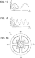
- FIG. 16 is a diagram illustrating a waveform of a current input to the electric motor 1 according to Embodiment 1.
- FIG. 17 is a diagram illustrating a waveform of a current input to an electric motor having eight magnetic poles according to a Comparative Example.
- the waveforms illustrated in FIGS. 16 and 17 are the waveforms of currents input to the electric motor 1 during one rotation of the rotor 3, and the carrier frequencies of these waveforms are equal to each other.
- the electrical frequency of the current input to the electric motor increases with increasing the number of magnetic poles, as illustrated in FIG. 15 .
- the electrical frequency doubles at a rotation speed of 1,000 rps.
- the waveform of a current input to an electric motor having eight magnetic poles is rougher than in the electric motor 1 ( FIG. 16 ) having four magnetic poles.
- the rougher the waveform of the current the poorer the controllability (for example, the control of rotation of a rotor) of the electric motor. Therefore, to drive the electric motor at a high speed of 10,000 rpm or more, for example, it is desired to use as few magnetic poles as possible, and lower the electrical frequency. This improves the controllability of the electric motor.
- the rotor 3 has four magnetic poles, and the stator 2 includes four teeth 21b. This makes it possible to enhance the controllability even when the electric motor is driven at a speed of 10,000 rpm or more, compared with an electric motor having six or more magnetic poles.
- the number of switching operations can be reduced, and the switching loss in high-speed rotation can be reduced, compared, for example, to driving by a three-phase inverter.
- Each yoke 21a is formed by the back yokes 211 and the joint parts 212.
- Each joint part 212 has a length from the tooth 21b toward the outer side in the radial direction, and each back yoke 211 has a length from the corresponding joint part 212 toward the inner side in the radial direction. This makes it possible to widen a region of a stator coil formed by the winding 26.
- FIG. 18 is a plan view schematically illustrating a structure of an electric motor 1a according to Comparative Example 1.
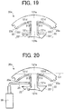
- FIG. 19 is a plan view schematically illustrating a structure of a split core 20a of the electric motor 1a according to Comparative Example 1.
- FIG. 20 is a diagram illustrating an example of a process of winding a winding 26 on the split core 20a.
- the electric motor 1a according to Comparative Example 1 has four magnetic poles and includes four teeth 121b, like the electric motor 1 according to this Embodiment.
- the electric motor 1a includes four split cores 20a.
- the teeth 121b correspond to the teeth 21b of the electric motor 1, and have the same structure as the teeth 21b.
- the structure of a yoke 121a is different from that of the yoke 21a of the electric motor 1 according to this Embodiment. More specifically, the maximum angle ⁇ 3 formed by each side surface 121c of the tooth 121b and a corresponding side surface 121d of the yoke 121a on the inner side in the radial direction is smaller than 90 degrees.
- Windings are wound around teeth, normally using a nozzle.
- a stator is not divided into a plurality of cores, since the nozzle needs to be inserted into a slot between teeth, it is difficult to wind the windings to achieve high density of stator coils.
- the stator 2 is divided into a plurality of cores, the winding 26 can easily be wound around each tooth 21b using a nozzle, and the density of stator coils can thus be increased. Note, however, that to prevent a positional shift of the position sensor 4, the winding 26 is desirably not wound near the position sensor 4.
- the split core 20 can be formed so that the split end portions 23a are located outside the straight line L1 in the radial direction and thus winding of the winding 26 is facilitated.
- FIG. 21 is a plan view schematically illustrating a structure of an electric motor 1b according to Comparative Example 2.
- FIG. 22 is a plan view schematically illustrating a structure of a split core 20b of the electric motor 1b according to Comparative Example 2.
- the electric motor 1b according to Comparative Example 2 has two magnetic poles and includes two teeth 221b.
- the electric motor 1b includes two split cores 20b.
- the structure of a yoke 221a is different from that of the yoke 21a of the electric motor 1 according to this Embodiment. More specifically, the maximum angle ⁇ 4 formed by a side surface 221c of the tooth 221b and a corresponding side surface 221d of the yoke 221a on the inner side in the radial direction is smaller than 90 degrees.
- the yoke 221a hampers the operation of a nozzle 30 in winding of a winding, and it is difficult to wind the winding especially around the outer portions of the tooth 221b in the radial direction.
- the number of magnetic poles and the number of teeth are desirably small in consideration of the controllability of the electric motor 1, while the number of magnetic poles is desirably four and the number of teeth is desirably four in consideration of winding of windings. Even if the number of magnetic poles is four and the number of teeth is four, when, as in the electric motor 1a according to Comparative Example 1, the maximum angle ⁇ 3 is smaller than 90 degrees, it is difficult to wind the windings 26.
- the electric motor 1 has four magnetic poles and includes four teeth 21b, and the angle ⁇ 1 (degrees) satisfies 90 degrees ⁇ ⁇ 1 ⁇ 180 degrees. This makes it possible to enhance the controllability of the electric motor 1, to obtain an advantage that winding of the windings 26 is facilitated, and thus to increase the density of stator coils.
- each joint part 212 has a length from the tooth 21b toward the outer side in the radial direction
- each back yoke 211 has a length from the corresponding joint part 212 toward the inner side in the radial direction. Accordingly, as illustrated in FIG. 6 , since the split core 20 can be formed so that the split end portions 23a are located outside the straight line L1 in the radial direction, winding of the winding 26 can be facilitated.
- the stator 2 satisfies ⁇ 2 > ⁇ 1, as illustrated in FIG. 7 .
- the first portions 221 of the insulator 22 extend in a direction perpendicular to the radial direction in a plane perpendicular to the rotation axis Ax of the rotor 3. This makes it possible to support the winding 26 by the first portions 221 of the insulator 22, and to prevent the winding 26 from coming apart.
- the number of turns of the winding 26 can be increased by forming the first portions 221 to be long in a direction perpendicular to the radial direction. However, the longer the first portions 221 in the direction perpendicular to the radial direction, the lower the rigidity against the stress F occurring on the first portions 221 due to winding of the winding 26.
- the position sensor 4 is fixed by the insulators 22 between two teeth 21b adjacent to each other. This makes it possible to downsize the electric motor 1.
- FIG. 23 is a plan view schematically illustrating a structure of an electric motor 1c according to Comparative Example 3.
- FIG. 24 is a plan view schematically illustrating a structure of a split core 20c of the electric motor 1c according to Comparative Example 3.
- the electric motor 1c according to Comparative Example 3 has four magnetic poles and includes four teeth 321b, like the electric motor 1 according to this Embodiment.
- the electric motor 1c includes four split cores 20c.
- the structure of a yoke 321a is different from that of the yoke 21a of the electric motor 1 according to this Embodiment. More specifically, the yoke 321a is formed in a straight line along a direction perpendicular to the radial direction.
- the angle ⁇ 5 formed by a side surface 321c of the tooth 321b and a corresponding side surface 321d of the yoke 321a on the inner side in the radial direction is 90 degrees. It is, therefore, possible to enhance the controllability of the electric motor 1c, to facilitate winding of a winding, and thus to obtain an advantage that the density of the winding is increased, as in the electric motor 1 according to the above-described Embodiment.
- FIG. 25 is a plan view illustrating the electric motor 1c according to Comparative Example 3 disposed in a frame 5.
- the frame 5 is a cylindrical frame. As illustrated in FIG. 25 , in the electric motor 1c, when contact portions 24c in contact with the inner peripheral surface of the frame 5 are in contact with the frame 5 by point contact, the stator 2c (that is, the four split cores 20c) is not stably fixed in the frame 5 and it is difficult to maintain the shape of the stator 2c.
- the contact portions in contact with the inner peripheral surface of the frame 5 are the outer peripheral surfaces 24 of the yokes 21a (more specifically, the back yokes 211) formed in arc shapes.
- the outer peripheral surfaces 24 are formed in arc shapes in a plane perpendicular to the rotation axis Ax of the rotor 3, and are therefore in contact with the frame 5 by surface contact. This makes it possible to obtain an advantage that fixing of the stator 2 is stabilized in the frame 5 and thus the shape of the stator 2 can easily be maintained.
- the tooth 21b and the pair of joint parts 212 form a Y shape. This makes it possible to reduce the material of the stator core 21. Furthermore, since the surface area of the stator core 21 and, more specifically, that of the yoke 21a can be increased, heat generated by the electric motor 1 can be efficiently dissipated outside the electric motor 1.
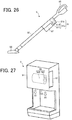
- FIG. 26 is a side view schematically illustrating a vacuum cleaner 8 (also simply called a "cleaner”) according to Embodiment 2 of the present invention.
- the vacuum cleaner 8 includes a main body 81, a dust collection part 82 (also called a dust collector), a duct 83, a suction nozzle 84, and a gripping portion 85.
- the main body 81 includes an electric blower 81a to generate suction force (more specifically, an air current), and an exhaust port 81b.
- the electric blower 81a includes a fan 811, and an electric motor 810 to rotate the fan 811.
- the electric motor 810 is identical to the electric motor 1 according to Embodiment 1 (including the modifications).
- the fan 811 rotates to generate an air current.
- the fan 811 includes, for example, blades and a shaft fixed to the blades, and the shaft is fixed to the electric motor 810.
- the electric blower 81a sends dust to the dust collection part 82 using suction force generated by driving the electric motor 810.
- the dust collection part 82 is mounted on the main body 81. However, the dust collection part 82 may be provided inside the main body 81.
- the dust collection part 82 is, for example, a container including a filter to separate dust and air.
- the suction nozzle 84 is mounted at the end of the duct 83.
- the vacuum cleaner 8 according to Embodiment 2 includes the electric motor 1 described in Embodiment 1 (including the modifications), and therefore has the same effects as those described in Embodiment 1.
- the controllability (for example, the accuracy of the control of rotation of a rotor) of the electric motor 810 can be enhanced, and the controllability (for example, the accuracy of suction control) of the vacuum cleaner 8 can thus be improved.
- FIG. 27 is a perspective view schematically illustrating a hand dryer 9 as a hand drying device according to Embodiment 3 of the present invention.
- the hand dryer 9 serving as a hand drying device includes a housing 91 and an electric blower 94.
- the housing 91 includes at least one air inlet 92 and at least one air outlet 93.
- the electric blower 94 is fixed in the housing 91.
- the electric blower 94 includes a fan 941, and an electric motor 940 to rotate the fan 941.
- the electric motor 940 is the electric motor 1 according to Embodiment 1 (including the modifications).
- the fan 941 rotates to generate an air current.
- the fan 941 includes, for example, blades and a shaft fixed to the blades, and the shaft is fixed to the electric motor 940.
- the electric blower 94 performs air suction and blowing by generating an air current. More specifically, the electric blower 94 sucks in air exterior to the housing 91 through the air inlet 92 and sends the air outside the housing 91 through the air outlet 93.
- the hand dryer 9 can exhaust two air currents Af through the air outlet 93.
- the two air currents Af generated by the electric blower 94 may be combined into one air current. In this case, one combined air current is exhausted through the air outlet 93.
- the user of the hand drier 9 can blow off waterdrops adhering to the hands and dry the hands.
- the hand dryer 9 according to Embodiment 3 includes the electric motor 1 described in Embodiment 1 (including the modifications), and therefore has the same effects as those described in Embodiment 1.
- the controllability (for example, the accuracy of the control of rotation of a rotor) of the electric motor 940 can be enhanced, and the controllability (for example, the accuracy of air blowing control) of the hand dryer 9 can thus be improved.
Landscapes
- Engineering & Computer Science (AREA)
- Power Engineering (AREA)
- Microelectronics & Electronic Packaging (AREA)
- Mechanical Engineering (AREA)
- Health & Medical Sciences (AREA)
- Public Health (AREA)
- Iron Core Of Rotating Electric Machines (AREA)
- Insulation, Fastening Of Motor, Generator Windings (AREA)
Abstract
Description
- The present invention relates to a stator of an electric motor.
- To facilitate winding of a winding on a stator of an electric motor, a stator core formed by a plurality of split cores is generally used. When winding of the windings on the stator is facilitated, the density of a stator coil or coils can be increased, and the motor efficiency thus improves. In an electric motor disclosed in, for example,
patent reference 1, a stator core is divided into 12 core constituent bodies, and the electric motor therefore includes 12 teeth. - Patent Reference 1: Japanese Patent Application Publication No.
2005-117844 - Normally, however, the larger the number of magnetic poles of an electric motor and the number of teeth of a stator, the higher the electrical frequency of a current input to the electric motor. This roughens the waveform of the current input to the electric motor, and thus degrades the controllability (for example, the control of rotation of a rotor) of the electric motor. Under the circumstances, to enhance the controllability of the electric motor in rotation at a speed as high as, for example, 10,000 rpm or more, it is desired to use as few magnetic poles and as few teeth as possible. A demand has, therefore, arisen for an electric motor that uses a small number of magnetic poles and a small number of teeth, and includes split cores facilitating winding of a winding on a stator.
- It is an object of the present invention to provide a stator having high controllability and facilitating winding of a winding on the stator.
- A stator according to the present invention is provided as a stator disposed outside a rotor of an electric motor, the stator including four split cores arranged in a circumferential direction about a rotation axis of the rotor, the split cores each including a tooth, and a yoke including a pair of joint parts each having a length from the tooth toward an outer side in a radial direction of the stator, wherein in a plane perpendicular to the rotation axis of the rotor, a shape of an end of the tooth in the radial direction is asymmetrical, and an angle θ1 (degrees) formed by a side surface of the tooth and a side surface of the yoke on an inner side in the radial direction of the stator satisfies 90 degrees < θ1 < 180 degrees.
- The present invention can provide a stator having high controllability and facilitating winding of a winding on the stator.
-
-
FIG. 1 is a plan view schematically illustrating a structure of an electric motor according toEmbodiment 1 of the present invention. -
FIG. 2 is a plan view schematically illustrating a structure of a split core. -
FIG. 3 is a plan view schematically illustrating a structure of a stator core. -
FIG. 4 is a plan view schematically illustrating the structure of the split core. -
FIG. 5 is a plan view schematically illustrating the structure of the split core. -
FIG. 6 is a plan view schematically illustrating the structure of the split core. -
FIG. 7 is a diagram illustrating a relationship between the shape of the end of a tooth and the shape of an insulator. -
FIG. 8 is a diagram illustrating a relationship between the thickness of a first portion of the insulator and the thickness of a second portion of the insulator. -
FIG. 9 is a diagram illustrating a relationship between the thickness of the first portion of the insulator and the thickness of the second portion of the insulator. -
FIG. 10 is a diagram illustrating a stress occurring on the insulator due to winding of a winding. -
FIG. 11 is a plan view schematically illustrating a structure of an electric motor including a stator fixed by caulking. -
FIG. 12 is a plan view schematically illustrating a structure of a split core including a stator core fixed by caulking. -
FIG. 13 is a plan view illustrating a structure of the electric motor further including a frame. -
FIG. 14 is a plan view illustrating another example of the electric motor. -
FIG. 15 is a diagram representing a relationship between the rotation speed (rps) of an electric motor and the electrical frequency (Hz) of a current input to the electric motor, for each magnetic pole count of a rotor. -
FIG. 16 is a diagram illustrating a waveform of a current input to the electric motor according toEmbodiment 1. -
FIG. 17 is a diagram illustrating a waveform of a current input to an electric motor having eight magnetic poles according to a Comparative Example. -
FIG. 18 is a plan view schematically illustrating a structure of an electric motor according to Comparative Example 1. -
FIG. 19 is a plan view schematically illustrating a structure of a split core of the electric motor according to Comparative Example 1. -
FIG. 20 is a diagram illustrating an example of a process of winding a winding on the split core of the electric motor according to Comparative Example 1. -
FIG. 21 is a plan view schematically illustrating a structure of an electric motor according to Comparative Example 2. -
FIG. 22 is a plan view schematically illustrating a structure of a split core of the electric motor according to Comparative Example 2. -
FIG. 23 is a plan view schematically illustrating a structure of an electric motor according to Comparative Example 3. -
FIG. 24 is a plan view schematically illustrating a structure of a split core of the electric motor according to Comparative Example 3. -
FIG. 25 is a plan view illustrating an electric motor according to Comparative Example 3 disposed in a frame. -
FIG. 26 is a side view schematically illustrating a vacuum cleaner according toEmbodiment 2 of the present invention. -
FIG. 27 is a perspective view schematically illustrating a hand dryer as a hand drying device according toEmbodiment 3 of the present invention. - Each drawing illustrates a structure of an
electric motor 1 and structures of components of theelectric motor 1 in a plane perpendicular to a rotation axis Ax of arotor 3. -
FIG. 1 is a plan view schematically illustrating a structure of theelectric motor 1 according toEmbodiment 1 of the present invention. An arrow D1 indicates the circumferential directions of astator 2 andstator cores 21 about the rotation axis Ax of therotor 3. The arrow D1 also indicates the circumferential direction of therotor 3 about the rotation axis Ax of therotor 3. The direction indicated by the arrow D1 will also be simply referred to as the "circumferential direction" hereinafter. Referring toFIG. 1 ,insulators 22 are illustrated in the shape of a cross-section in a plane perpendicular to the rotation axis Ax of therotor 3. -
FIG. 2 is a plan view schematically illustrating a structure of a splitcore 20. Referring toFIG. 2 , theinsulator 22 and a winding 26 are illustrated in the shape of a cross-section perpendicular to the rotation axis Ax of therotor 3. In other drawings as well, theinsulator 22 and thewinding 26 are illustrated in the shape of a cross-section perpendicular to the rotation axis Ax of therotor 3. An arrow D2 indicates the radial directions of thestator 2, thestator cores 21, and the rotor 3 (to be also simply referred to as the "radial direction" hereinafter). An arrow D21 indicates the "inner side in the radial direction," and an arrow D22 indicates the "outer side in the radial direction." -
FIG. 3 is a plan view schematically illustrating a structure of thestator core 21. -
FIGS. 4 to 6 are plan views schematically illustrating the structure of thesplit core 20. - The
electric motor 1 includes thestator 2 and therotor 3. Theelectric motor 1 is designed as, for example, a permanent magnet synchronous motor. - The
electric motor 1 is driven by, for example, a single-phase inverter. When theelectric motor 1 is driven by a single-phase inverter, the number of switching operations can be reduced, and the switching loss in high-speed rotation can be reduced, compared, for example, to driving by a three-phase inverter. In high-speed rotation, since the electrical frequency becomes high and the number of switching operations increase, the advantage of using a single-phase inverter is obtained especially in high-speed rotation. - When the number of switching operations in the inverter is small, the waveform of a current input to the
electric motor 1 is distorted, and the iron loss in thestator 2 is increased by the harmonic components of the current. Therefore, in place of electrical steel sheets, materials such as amorphous metals are desirably used as the materials of thestator cores 21 of thestator 2. This makes it possible to reduce the occurrence of iron losses in thestator 2 to keep down degradation in motor efficiency. - The
stator 2 includes at least onestator core 21, at least oneinsulator 22, a plurality of split faces 23, a position sensor 4, and at least one winding 26. Thestator 2 is disposed outside therotor 3 through an air gap. Therotor 3 is disposed inside thestator 2 through the air gap. Theinsulators 22 insulate thestator cores 21. Thewindings 26 are wound on thestator cores 21 and, more specifically, aroundteeth 21b through theinsulators 22. Accordingly, at least one winding 26 is wound around theinsulator 22. Thewindings 26 are wound around theteeth 21b by, for example, concentrated winding. - The stator 2 (more specifically, the plurality of stator cores 21) includes a plurality of
yokes 21a and a plurality ofteeth 21b. Thestator cores 21 are formed of, for example, a plurality of amorphous metals or a plurality of electrical steel sheets that are laminated. - The
insulators 22 are disposed inslots 27 implemented as regions each formed between twoteeth 21b adjacent to each other. More specifically, theinsulators 22 are fixed to the side surfaces of thestator cores 21. Theinsulators 22 are made of, for example, an insulating resin. - Outer
peripheral surfaces 24 of thestator cores 21 are formed in arc shapes. More specifically, the outerperipheral surfaces 24 are the outer peripheral surfaces of theyokes 21a formed outermost in the radial direction. - The
rotor 3 includes a plurality of permanent magnets and form a plurality of magnetic poles. In this Embodiment, therotor 3 has four magnetic poles. - The position sensor 4 includes, for example, a Hall element to detect a magnetic field emanating from the
rotor 3. Hence, the position sensor 4 can detect a magnetic field emanating from therotor 3. The position sensor 4 is disposed adjacent to theteeth 21b in the circumferential direction. More specifically, the position sensor 4 is fixed by at least oneinsulator 22 between twoteeth 21b adjacent to each other. The position sensor 4 is mounted in, for example, a recess formed in theinsulator 22. This makes it possible to downsize theelectric motor 1. The position sensor 4 may even be fixed by twoinsulators 22 adjacent to each other. - Control of the
electric motor 1 can be facilitated by using the position sensor 4 to detect a magnetic field emanating from therotor 3, and further detecting the rotation position (more specifically, the phase) of therotor 3. Moreover, since the position sensor 4 is fixed between the twoteeth 21b, it is possible to prevent theelectric motor 1 from getting larger and to downsize theelectric motor 1. - The structure of the
split cores 20 will be described below. - The
stator 2 includes a plurality ofsplit cores 20 arranged in the circumferential direction, as illustrated inFIG. 1 . In this Embodiment, thestator 2 is formed by foursplit cores 20 arranged in the circumferential direction. - The
stator 2 is divided into parts equal in number to theteeth 21b. In other words, thestator 2 is divided into foursplit cores 20. Accordingly, thestator 2 includes fouryokes 21a and fourteeth 21b. - Each
split core 20 includes thestator core 21 and theinsulator 22. Eachstator core 21 includes oneyoke 21a, onetooth 21b extending in the radial direction from theyoke 21a, and two split faces 23. Each split face 23 is formed at an end of theyoke 21a of eachstator core 21 in the circumferential direction.Split end portions 23a illustrated inFIG. 3 are the inner ends of the respective split faces 23 in the radial direction. - In each
split core 20, theinsulator 22 is mounted on thestator core 21, and at least one winding 26 is wound around theinsulator 22. Accordingly, theinsulator 22 and at least one winding 26 also serve as components of thesplit core 20. - The
yoke 21a includes at least one pair ofback yokes 211 and at least one pair ofjoint parts 212. Eachjoint part 212 has a length from thetooth 21b toward the outer side in the radial direction, and eachback yoke 211 has a length from the correspondingjoint part 212 toward the inner side in the radial direction. More specifically, eachback yoke 211 extends in the circumferential direction. Thetooth 21b extends inwards in the radial direction from theyoke 21a. - In a plane perpendicular to the rotation axis Ax of the
rotor 3, thetooth 21b and the pair ofjoint parts 212 form a Y shape. This makes it possible to reduce the material of thestator core 21. Furthermore, since the surface area of thestator core 21, more specifically, the surface area of theyoke 21a can be increased, heat generated by theelectric motor 1 can be efficiently dissipated outside theelectric motor 1. Eachjoint part 212 and thecorresponding back yoke 211 may even be formed in a straight line. In this case, in the plane perpendicular to the rotation axis Ax of therotor 3, theyoke 21a and thetooth 21b form a Y shape as a whole. Theyoke 21a may even include noback yokes 211, and may include only the pair ofjoint parts 212. In this case as well, in the plane perpendicular to the rotation axis Ax of therotor 3, theyoke 21a and thetooth 21b form a Y shape as a whole. - The angle θ1 (degrees) formed by each
side surface 21c of thetooth 21b and acorresponding side surface 21d of theyoke 21a on the inner side in the radial direction satisfies 90 degrees < θ1 < 180 degrees, as illustrated inFIG. 3 . The side surfaces 21d of theyoke 21a also serve more specifically as the side surfaces of thejoint parts 212. In other words, the angle θ1 (degrees) formed by eachside surface 21c of thetooth 21b and theside surface 21d of the correspondingjoint part 212 on the inner side in the radial direction satisfies 90 degrees < θ1 < 180 degrees. The side surfaces 21c of thetooth 21b are surfaces extending in the radial direction, that is, surfaces on the both sides of thetooth 21b in a direction perpendicular to the radial direction. The side surfaces 21d of theyoke 21a are adjacent to the side surfaces 21c of thetooth 21b. - When the angle θ1 (degrees) satisfies 90 degrees < θ1 < 180 degrees, winding of the winding 26 around the
tooth 21b can be facilitated. As a result, theelectric motor 1 can be miniaturized, and the density of the winding 26 can be increased. - In a plane perpendicular to the rotation axis Ax of the
rotor 3, the shape of anend 213 of thetooth 21b in the radial direction (more specifically, on the inner side in the radial direction) is asymmetrical. With this structure, when therotor 3 has four magnetic poles, that is, when the number of magnetic poles on therotor 3 is equal to the number ofteeth 21b, the magnetic pole center of therotor 3 is located on the right with respect to a straight line A1 illustrated inFIG. 3 (that is, on the downstream side in the direction in which therotor 3 rotates) while therotor 3 is stopped, due to the differences in size of the air gap between thestator 2 and therotor 3. Hence, supplying a magnetic field from thestator 2 to therotor 3 in starting theelectric motor 1 makes it possible to set the direction in which therotor 3 rotates to one direction (more specifically, from the upstream side to the downstream side). If the shape of theend 213 of thetooth 21b is symmetrical in the circumferential direction, and the air gap is uniform in the circumferential direction, the magnetic pole center of therotor 3 is located on the straight line A1 while therotor 3 is stopped. In this case, therotor 3 may rotate in the reverse direction when a magnetic field is supplied from thestator 2 to therotor 3. - In the example illustrated in
FIG. 3 , in a plane perpendicular to the rotation axis Ax of therotor 3, the shape of theend 213 differs between the left and right sides of theend 213 with respect to the straight line A1 passing through the center of thestator core 21. In other words, the shape of theend 213 differs between the upstream and downstream sides in the direction in which therotor 3 rotates. In the example illustrated inFIG. 3 , the upstream side in the direction in which therotor 3 rotates corresponds to the left side with respect to the straight line A1, and the downstream side in this direction corresponds to the right side with respect to the straight line A1. - The
end 213 on the upstream side in the direction in which therotor 3 rotates extends linearly. Theend 213 on the downstream side in the direction in which therotor 3 rotates is curved in an arc shape along the outer peripheral surface of therotor 3. Accordingly, the air gap between thestator 2 and therotor 3 on the upstream side in the direction in which therotor 3 rotates is larger than that on the downstream side in this direction. In other words, the gap between thestator 2 and therotor 3 is larger on one side (that is, the upstream side) in the circumferential direction than on the other side (that is, the downstream side) in this direction. - The thickness t3 of the end portion of the
tooth 21b on the downstream side is larger than the thickness t4 of the end portion of thetooth 21b on the upstream side. The end portion of thetooth 21b extends in the circumferential direction. The thickness t3 is the thickness, in the radial direction, of the end portion of thetooth 21b on the downstream end. The thickness t4 is the thickness, in the radial direction, of the end portion of thetooth 21b on the upstream end. Normally, in each tooth of a stator, magnetic flux from a rotor flows in a concentrated manner on the downstream side of this tooth where an air gap is small. In this case, the magnetic flux density increases at an end of the downstream side of the end portion of the tooth, and the iron loss increases at the end of the downstream side. On the other hand, in the example illustrated inFIG. 3 , since the thickness t3 of the end portion of thetooth 21b on the downstream side is larger than the thickness t4 of the end portion of thetooth 21b on the upstream side, an increase in magnetic flux density on the downstream side of the end portion of thetooth 21b can be kept down and an increase in iron loss can be kept down. - The shape of the
end 213, however, is not limited to this Embodiment as long as the shape of theend 213 is asymmetrical. - The
insulator 22 includes a pair offirst portions 221 and a pair ofsecond portions 222, as illustrated inFIG. 4 . The pair offirst portions 221 may be separated from each other, or integrated with each other. The pair ofsecond portions 222 may also be separated from each other, or integrated with each other. - The
first portions 221 are disposed on both sides of thetooth 21b in a plane perpendicular to the rotation axis Ax of therotor 3, as illustrated inFIG. 4 . In other words, thefirst portions 221 face the side surfaces 21c of thetooth 21b. Thefirst portions 221 extend in a direction perpendicular to the radial direction in the plane perpendicular to the rotation axis Ax of therotor 3. Thefirst portions 221 includeside surfaces 22d. The side surfaces 22d extend in the direction perpendicular to the radial direction in the plane perpendicular to the rotation axis Ax of therotor 3. - The
second portions 222 face thetooth 21b and thejoint parts 212. More specifically, thesecond portions 222 face the side surfaces 21d of theyoke 21a and the side surfaces 21c of thetooth 21b. Thesecond portions 222 insulate the side surfaces 21d of theyoke 21a and the side surfaces 21c of thetooth 21b. Therefore, theinsulator 22 insulates theyoke 21a and thetooth 21b. Thesecond portions 222 may face the back yokes 211. - The angle θ2 (degrees) formed by each
side surface 22a of theinsulator 22 fixed to thetooth 21b and acorresponding side surface 22b of theinsulator 22 fixed to theyoke 21a satisfies 90 degrees < θ2 < 180 degrees, as illustrated inFIG. 5 . The side surfaces 22b are adjacent to the side surfaces 22a. - When the angle θ2 (degrees) satisfies 90 degrees < θ1 < 180 degrees, winding of the winding 26 around the
tooth 21b can be facilitated. As a result, theelectric motor 1 can be miniaturized, and the density of the winding 26 can be increased. - The
split end portions 23a are located outside a straight line L1 in the radial direction, as illustrated inFIG. 6 . The straight line L1 serves as the boundary between theyoke 21a and thetooth 21b. In other words, the straight line L1 serves as the boundary between each of the side surfaces 21d of theyoke 21a and each of the side surfaces 21c of thetooth 21b. - Similarly,
end portions 22c that are the ends of theinsulator 22 in the circumferential direction are located outside the straight line L1 in the radial direction. This makes it possible to obtain an advantage that winding of the winding 26 is facilitated and to increase the density of a stator coil. -
FIG. 7 is a diagram illustrating a relationship between the shape of theend 213 of thetooth 21b and the shape of the insulator 22 (more specifically, the first portions 221). - An angle α1 represents the angle formed by two straight lines L2 passing through the rotation axis Ax and both ends E1 of the
end 213 of thetooth 21b in a direction perpendicular to the radial direction in a plane perpendicular to the rotation axis Ax of therotor 3. An angle α2 represents the angle formed by two straight lines L3 passing through the rotation axis Ax and both ends E2 of the pair offirst portions 221 in the direction perpendicular to the radial direction in the plane perpendicular to the rotation axis Ax of therotor 3. In this case, the relationship between the angles α1 and α2 is given by α2 > α1. The ends E2 are the ends of the side surfaces 22d in the direction perpendicular to the radial direction, in the plane perpendicular to the rotation axis Ax of therotor 3. - When the
stator 2 satisfies α2 > α1, the insulator 22 (more specifically, the first portions 221) extends in a direction perpendicular to the radial direction. More specifically, the insulator 22 (more specifically, the first portions 221) can be formed to be longer in the direction perpendicular to the radial direction than theend 213 of thetooth 21b. In other words, the insulator 22 (more specifically, the first portions 221) can be formed so that the side surfaces 22d of thefirst portions 221 are longer than theend 213 of thetooth 21b in the direction perpendicular to the radial direction. This makes it possible to wind the winding 26 around theinsulator 22 with a larger number of turns and to support the winding 26 by the side surfaces 22d. -
FIGS. 8 and9 are diagrams each illustrating a relationship between the thickness of thefirst portion 221 of theinsulator 22 and the thickness of thesecond portion 222 of theinsulator 22. - The thickness t2 of the
first portion 221 of theinsulator 22 is the maximum thickness of thefirst portion 221 in the direction along a straight line L5, in a plane perpendicular to the rotation axis Ax of therotor 3, as illustrated inFIG. 9 . The straight line L5 is a straight line passing through a contact point C4 and a center C3 of the winding 26, in the plane perpendicular to the rotation axis Ax of therotor 3, as illustrated inFIG. 9 . The center C3 of the winding 26 is the center of the winding 26 abutting against thefirst portion 221, in the plane perpendicular to the rotation axis Ax of therotor 3. The contact point C4 is the contact point between thefirst portion 221 and the winding 26 abutting against thefirst portion 221, in the plane perpendicular to the rotation axis Ax of therotor 3. - The thickness t1 of the
second portion 222 of theinsulator 22 is the minimum thickness of thesecond portion 222 in the direction along a straight line L4, in a plane perpendicular to the rotation axis Ax of therotor 3, as illustrated inFIG. 9 . The straight line L4 is a straight line passing through a contact point C2 and a center C1 of the winding 26, in the plane perpendicular to the rotation axis Ax of therotor 3, as illustrated inFIG. 9 . The center C1 of the winding 26 is the center of the winding 26 abutting against thesecond portion 222, in the plane perpendicular to the rotation axis Ax of therotor 3. The contact point C2 is the contact point between thesecond portion 222 and the winding 26 abutting against thesecond portion 222, in the plane perpendicular to the rotation axis Ax of therotor 3. - In the example illustrated in
FIGS. 8 and9 , the relationship between the maximum thickness t2 of thefirst portion 221 and the minimum thickness t1 of thesecond portion 222 satisfies t2 > t1. -
FIG. 10 is a diagram illustrating a stress F occurring on theinsulator 22 due to winding of the winding 26. - When the
stator 2 satisfies t2 > t1, the rigidity of portions of theinsulator 22 that are not supported by thestator core 21, that is, thefirst portions 221 of theinsulator 22 can be maintained similarly to thesecond portions 222 of theinsulator 22. In other words, when thestator 2 satisfies t2 > t1, the rigidity against the stress F occurring on thefirst portions 221 due to winding of the winding 26 can be enhanced. This makes it possible to prevent deformation of thefirst portions 221 of theinsulator 22. - Although
FIGS. 8 to 10 each illustrate only the relationship between the maximum thickness t2 and the minimum thickness t1 of thesecond portion 222 in theinsulator 22 disposed on the right side of thetooth 21b, theinsulator 22 disposed on the left side of thetooth 21b may even hold the relationship between the maximum thickness t2 and the minimum thickness t1 of thesecond portion 222 in theinsulator 22 lying on the right side, that is, t2 > t1. In this case, theinsulator 22 lying on the left side also has the effects of the above-mentionedinsulator 22 lying on the right side. -
FIG. 11 is a plan view schematically illustrating a structure of theelectric motor 1 including thestator 2 fixed by caulking. -
FIG. 12 is a plan view schematically illustrating a structure of thesplit core 20 including thestator core 21 fixed by caulking. -
Caulked parts 25 illustrated inFIGS. 11 and 12 are portions fixed by caulking. - A plurality of amorphous metals or a plurality of electrical steel sheets forming the
stator cores 21 may be fixed by caulking in the caulkedparts 25, as illustrated inFIGS. 11 and 12 . In theelectric motor 1 illustrated inFIG. 11 and thesplit core 20 illustrated inFIG. 12 , structures other than the caulkedparts 25 are the same as those of theelectric motor 1 and thesplit core 20, respectively, illustrated inFIGS. 1 to 10 . - The use of caulking makes it possible to stabilize the shapes of the
stator cores 21 and, in turn, to stabilize the shapes of the split faces 23. Accordingly, when, for example, the frame 5 (FIG. 13 ) is fitted to theelectric motor 1 by shrink fitting, thesplit cores 20 can be prevented from coming apart at the split faces 23. -
FIG. 13 is a plan view illustrating a structure of theelectric motor 1 further including theframe 5. InFIG. 13 , theframe 5 is illustrated in the shape of a cross-section in a plane perpendicular to the rotation axis Ax of therotor 3. - The
frame 5 covers thestator 2 of theelectric motor 1. Theframe 5 has, for example, a cylindrical shape. Contact portions in contact with the inner peripheral surface of theframe 5 are outerperipheral surfaces 24 of theyokes 21a (more specifically, the back yokes 211) formed in arc shapes. The outerperipheral surfaces 24 are formed in arc shapes, and are therefore in contact with theframe 5 by surface contact. This makes it possible to obtain an advantage that fixing of thestator 2 is stabilized in theframe 5 and the shape of thestator 2 can easily be maintained. -
Spaces 6 exist between theyokes 21a and theframe 5. More specifically, thespaces 6 exist between theframe 5 and thejoint parts 212 of theyokes 21a. This makes it possible to easily dissipate heat generated by theelectric motor 1 from thespaces 6 to the exterior of theelectric motor 1. As a result, a rise in temperature of theelectric motor 1 can be reduced, and the efficiency of theelectric motor 1 can thus be improved. -
FIG. 14 is a plan view illustrating another example of theelectric motor 1. - The
electric motor 1 illustrated inFIG. 14 includes no position sensor 4. In other words, even in theelectric motor 1 including no position sensor 4, the structure of the above-mentionedelectric motor 1 can be employed, and then the same effects as those of theelectric motor 1 illustrated inFIG. 1 are exhibited. Moreover, when no position sensor 4 is used, in eachsplit core 20, the maximum thickness t2 of each of the pair offirst portions 221 of theinsulator 22 can be set larger, and therefore the rigidity of both of the pair offirst portions 221 against the stress F of the winding 26 can further be enhanced. - The effects of the
electric motor 1 according to the Embodiment will further be described below. -
FIG. 15 is a diagram representing a relationship between the rotation speed (rps) of an electric motor and the electrical frequency (Hz) of a current input to the electric motor, for each magnetic pole count of a rotor. More specifically,FIG. 15 is a graph representing the relationship between the rotation speed of an electric motor and the electrical frequency when the number of magnetic poles of the electric motor is changed. Referring toFIG. 15 , f1 indicates the relationship between the rotation speed and the electrical frequency in theelectric motor 1 according to this Embodiment. f2 indicates the relationship between the rotation speed and the electrical frequency in an electric motor having six magnetic poles and six teeth. f3 indicates the relationship between the rotation speed and the electrical frequency in an electric motor having eight magnetic poles and eight teeth. f4 indicates the relationship between the rotation speed and the electrical frequency in an electric motor having 10 magnetic poles and 10 teeth. -
FIG. 16 is a diagram illustrating a waveform of a current input to theelectric motor 1 according toEmbodiment 1. -
FIG. 17 is a diagram illustrating a waveform of a current input to an electric motor having eight magnetic poles according to a Comparative Example. The waveforms illustrated inFIGS. 16 and 17 are the waveforms of currents input to theelectric motor 1 during one rotation of therotor 3, and the carrier frequencies of these waveforms are equal to each other. - The electrical frequency of the current input to the electric motor increases with increasing the number of magnetic poles, as illustrated in
FIG. 15 . For example, by comparison with the case that the number of magnetic poles is four, in the case that the number of magnetic poles is eight, the electrical frequency doubles at a rotation speed of 1,000 rps. Accordingly, as illustrated inFIG. 17 , when the carrier frequency is kept constant, the waveform of a current input to an electric motor having eight magnetic poles is rougher than in the electric motor 1 (FIG. 16 ) having four magnetic poles. The rougher the waveform of the current, the poorer the controllability (for example, the control of rotation of a rotor) of the electric motor. Therefore, to drive the electric motor at a high speed of 10,000 rpm or more, for example, it is desired to use as few magnetic poles as possible, and lower the electrical frequency. This improves the controllability of the electric motor. - As described above, to improve the controllability of the
electric motor 1, in theelectric motor 1 according to this Embodiment, therotor 3 has four magnetic poles, and thestator 2 includes fourteeth 21b. This makes it possible to enhance the controllability even when the electric motor is driven at a speed of 10,000 rpm or more, compared with an electric motor having six or more magnetic poles. - When the
electric motor 1 is driven by a single-phase inverter, the number of switching operations can be reduced, and the switching loss in high-speed rotation can be reduced, compared, for example, to driving by a three-phase inverter. - Each
yoke 21a is formed by theback yokes 211 and thejoint parts 212. Eachjoint part 212 has a length from thetooth 21b toward the outer side in the radial direction, and eachback yoke 211 has a length from the correspondingjoint part 212 toward the inner side in the radial direction. This makes it possible to widen a region of a stator coil formed by the winding 26. -
FIG. 18 is a plan view schematically illustrating a structure of anelectric motor 1a according to Comparative Example 1. -
FIG. 19 is a plan view schematically illustrating a structure of asplit core 20a of theelectric motor 1a according to Comparative Example 1. -
FIG. 20 is a diagram illustrating an example of a process of winding a winding 26 on thesplit core 20a. - The
electric motor 1a according to Comparative Example 1 has four magnetic poles and includes fourteeth 121b, like theelectric motor 1 according to this Embodiment. Theelectric motor 1a includes foursplit cores 20a. Theteeth 121b correspond to theteeth 21b of theelectric motor 1, and have the same structure as theteeth 21b. In theelectric motor 1a, the structure of ayoke 121a is different from that of theyoke 21a of theelectric motor 1 according to this Embodiment. More specifically, the maximum angle θ3 formed by eachside surface 121c of thetooth 121b and acorresponding side surface 121d of theyoke 121a on the inner side in the radial direction is smaller than 90 degrees. - Windings are wound around teeth, normally using a nozzle. When a stator is not divided into a plurality of cores, since the nozzle needs to be inserted into a slot between teeth, it is difficult to wind the windings to achieve high density of stator coils. On the other hand, in this Embodiment, since the
stator 2 is divided into a plurality of cores, the winding 26 can easily be wound around eachtooth 21b using a nozzle, and the density of stator coils can thus be increased. Note, however, that to prevent a positional shift of the position sensor 4, the winding 26 is desirably not wound near the position sensor 4. - However, in the
electric motor 1a illustrated inFIGS. 18 and19 , since the maximum angle θ3 is smaller than 90 degrees, splitend portions 23a are located inside the straight line L1 in the radial direction, as illustrated inFIG. 20 . With this arrangement, theyoke 121a hampers the operation of anozzle 30, and it is difficult to wind the winding 26 especially around the outer portions of thetooth 121b in the radial direction. In contrast to this, in theelectric motor 1 according to this Embodiment, the angle θ1 (degrees) satisfies 90 degrees < θ1 < 180 degrees. Accordingly, with theelectric motor 1 according to this Embodiment, it is possible to obtain an advantage that thesplit core 20 can be formed so that thesplit end portions 23a are located outside the straight line L1 in the radial direction and thus winding of the winding 26 is facilitated. -
FIG. 21 is a plan view schematically illustrating a structure of anelectric motor 1b according to Comparative Example 2. -
FIG. 22 is a plan view schematically illustrating a structure of asplit core 20b of theelectric motor 1b according to Comparative Example 2. - The
electric motor 1b according to Comparative Example 2 has two magnetic poles and includes twoteeth 221b. Theelectric motor 1b includes two splitcores 20b. In theelectric motor 1b, the structure of ayoke 221a is different from that of theyoke 21a of theelectric motor 1 according to this Embodiment. More specifically, the maximum angle θ4 formed by aside surface 221c of thetooth 221b and acorresponding side surface 221d of theyoke 221a on the inner side in the radial direction is smaller than 90 degrees. - As in the
electric motor 1a according to Comparative Example 1, therefore, since the maximum angle θ4 is smaller than 90 degrees also in theelectric motor 1b, theyoke 221a hampers the operation of anozzle 30 in winding of a winding, and it is difficult to wind the winding especially around the outer portions of thetooth 221b in the radial direction. - As described above with reference to
FIG. 15 , the number of magnetic poles and the number of teeth are desirably small in consideration of the controllability of theelectric motor 1, while the number of magnetic poles is desirably four and the number of teeth is desirably four in consideration of winding of windings. Even if the number of magnetic poles is four and the number of teeth is four, when, as in theelectric motor 1a according to Comparative Example 1, the maximum angle θ3 is smaller than 90 degrees, it is difficult to wind thewindings 26. - Accordingly, in this Embodiment, the
electric motor 1 has four magnetic poles and includes fourteeth 21b, and the angle θ1 (degrees) satisfies 90 degrees < θ1 < 180 degrees. This makes it possible to enhance the controllability of theelectric motor 1, to obtain an advantage that winding of thewindings 26 is facilitated, and thus to increase the density of stator coils. - In this Embodiment, each
joint part 212 has a length from thetooth 21b toward the outer side in the radial direction, and eachback yoke 211 has a length from the correspondingjoint part 212 toward the inner side in the radial direction. Accordingly, as illustrated inFIG. 6 , since thesplit core 20 can be formed so that thesplit end portions 23a are located outside the straight line L1 in the radial direction, winding of the winding 26 can be facilitated. - The
stator 2 satisfies α2 > α1, as illustrated inFIG. 7 . In other words, thefirst portions 221 of theinsulator 22 extend in a direction perpendicular to the radial direction in a plane perpendicular to the rotation axis Ax of therotor 3. This makes it possible to support the winding 26 by thefirst portions 221 of theinsulator 22, and to prevent the winding 26 from coming apart. - The number of turns of the winding 26 can be increased by forming the
first portions 221 to be long in a direction perpendicular to the radial direction. However, the longer thefirst portions 221 in the direction perpendicular to the radial direction, the lower the rigidity against the stress F occurring on thefirst portions 221 due to winding of the winding 26. - As illustrated in
FIGS. 8 to 10 , when the relationship between the maximum thickness t2 of thefirst portion 221 and the minimum thickness t1 of thesecond portion 222 satisfies t2 > t1, the rigidity against the stress F occurring due to winding of the winding 26 can be enhanced. This makes it possible to prevent deformation of portions of theinsulator 22 that are not supported by thestator core 21, that is, thefirst portions 221 of theinsulator 22. - The position sensor 4 is fixed by the
insulators 22 between twoteeth 21b adjacent to each other. This makes it possible to downsize theelectric motor 1. -
FIG. 23 is a plan view schematically illustrating a structure of anelectric motor 1c according to Comparative Example 3. -
FIG. 24 is a plan view schematically illustrating a structure of asplit core 20c of theelectric motor 1c according to Comparative Example 3. - The
electric motor 1c according to Comparative Example 3 has four magnetic poles and includes fourteeth 321b, like theelectric motor 1 according to this Embodiment. Theelectric motor 1c includes four splitcores 20c. In theelectric motor 1c, the structure of ayoke 321a is different from that of theyoke 21a of theelectric motor 1 according to this Embodiment. More specifically, theyoke 321a is formed in a straight line along a direction perpendicular to the radial direction. In theelectric motor 1c, the angle θ5 formed by aside surface 321c of thetooth 321b and acorresponding side surface 321d of theyoke 321a on the inner side in the radial direction is 90 degrees. It is, therefore, possible to enhance the controllability of theelectric motor 1c, to facilitate winding of a winding, and thus to obtain an advantage that the density of the winding is increased, as in theelectric motor 1 according to the above-described Embodiment. -
FIG. 25 is a plan view illustrating theelectric motor 1c according to Comparative Example 3 disposed in aframe 5. - The
frame 5 is a cylindrical frame. As illustrated inFIG. 25 , in theelectric motor 1c, whencontact portions 24c in contact with the inner peripheral surface of theframe 5 are in contact with theframe 5 by point contact, thestator 2c (that is, the foursplit cores 20c) is not stably fixed in theframe 5 and it is difficult to maintain the shape of thestator 2c. - As illustrated in
FIG. 13 , in theelectric motor 1 according to the above-described Embodiment, the contact portions in contact with the inner peripheral surface of theframe 5 are the outerperipheral surfaces 24 of theyokes 21a (more specifically, the back yokes 211) formed in arc shapes. The outerperipheral surfaces 24 are formed in arc shapes in a plane perpendicular to the rotation axis Ax of therotor 3, and are therefore in contact with theframe 5 by surface contact. This makes it possible to obtain an advantage that fixing of thestator 2 is stabilized in theframe 5 and thus the shape of thestator 2 can easily be maintained. - In a plane perpendicular to the rotation axis Ax of the
rotor 3, thetooth 21b and the pair ofjoint parts 212 form a Y shape. This makes it possible to reduce the material of thestator core 21. Furthermore, since the surface area of thestator core 21 and, more specifically, that of theyoke 21a can be increased, heat generated by theelectric motor 1 can be efficiently dissipated outside theelectric motor 1. - As illustrated in
FIG. 13 , when thestator 2 is fixed in theframe 5, thespaces 6 exist between theyokes 21a and theframe 5. This makes it possible to easily dissipate heat generated by theelectric motor 1 from thespaces 6 to the exterior of theelectric motor 1. As a result, a rise in temperature of theelectric motor 1 can be reduced, and the efficiency of theelectric motor 1 can thus be improved. -
FIG. 26 is a side view schematically illustrating a vacuum cleaner 8 (also simply called a "cleaner") according toEmbodiment 2 of the present invention. - The
vacuum cleaner 8 includes amain body 81, a dust collection part 82 (also called a dust collector), aduct 83, asuction nozzle 84, and a grippingportion 85. - The
main body 81 includes anelectric blower 81a to generate suction force (more specifically, an air current), and anexhaust port 81b. - The
electric blower 81a includes afan 811, and anelectric motor 810 to rotate thefan 811. Theelectric motor 810 is identical to theelectric motor 1 according to Embodiment 1 (including the modifications). When theelectric motor 810 is driven, thefan 811 rotates to generate an air current. Thefan 811 includes, for example, blades and a shaft fixed to the blades, and the shaft is fixed to theelectric motor 810. Theelectric blower 81a sends dust to thedust collection part 82 using suction force generated by driving theelectric motor 810. - The
dust collection part 82 is mounted on themain body 81. However, thedust collection part 82 may be provided inside themain body 81. Thedust collection part 82 is, for example, a container including a filter to separate dust and air. Thesuction nozzle 84 is mounted at the end of theduct 83. - When the
vacuum cleaner 8 is powered on, power is supplied to theelectric blower 81a and thus theelectric blower 81a is driven. During driving of theelectric blower 81a, dust is sucked in through thesuction nozzle 84 by suction force generated by theelectric blower 81a. Air currents generated by rotation of thefan 811 are combined together in thesuction nozzle 84 and theduct 83. The dust sucked in through thesuction nozzle 84 passes through theduct 83 and is collected in thedust collection part 82. The air sucked in through thesuction nozzle 84 passes through theelectric blower 81a and is exhausted outside thevacuum cleaner 8 through theexhaust port 81b. - The
vacuum cleaner 8 according toEmbodiment 2 includes theelectric motor 1 described in Embodiment 1 (including the modifications), and therefore has the same effects as those described inEmbodiment 1. - With the
vacuum cleaner 8 according toEmbodiment 2, the controllability (for example, the accuracy of the control of rotation of a rotor) of theelectric motor 810 can be enhanced, and the controllability (for example, the accuracy of suction control) of thevacuum cleaner 8 can thus be improved. -
FIG. 27 is a perspective view schematically illustrating ahand dryer 9 as a hand drying device according toEmbodiment 3 of the present invention. - The
hand dryer 9 serving as a hand drying device includes ahousing 91 and anelectric blower 94. Thehousing 91 includes at least oneair inlet 92 and at least oneair outlet 93. Theelectric blower 94 is fixed in thehousing 91. - The
electric blower 94 includes afan 941, and anelectric motor 940 to rotate thefan 941. Theelectric motor 940 is theelectric motor 1 according to Embodiment 1 (including the modifications). When theelectric motor 940 is driven, thefan 941 rotates to generate an air current. Thefan 941 includes, for example, blades and a shaft fixed to the blades, and the shaft is fixed to theelectric motor 940. Theelectric blower 94 performs air suction and blowing by generating an air current. More specifically, theelectric blower 94 sucks in air exterior to thehousing 91 through theair inlet 92 and sends the air outside thehousing 91 through theair outlet 93. - When the
hand dryer 9 is powered on, power is supplied to theelectric blower 94 and thus theelectric blower 94 is driven. During driving of theelectric blower 94, air exterior to thehand dryer 9 is sucked in through theair inlet 92. The air sucked in through theair inlet 92 passes through the inside of theelectric blower 94 and is discharged through theair outlet 93. - In this Embodiment, the
hand dryer 9 can exhaust two air currents Af through theair outlet 93. Note, however, that the two air currents Af generated by theelectric blower 94 may be combined into one air current. In this case, one combined air current is exhausted through theair outlet 93. - By placing hands close to the
air outlet 93, the user of the hand drier 9 can blow off waterdrops adhering to the hands and dry the hands. - The
hand dryer 9 according toEmbodiment 3 includes theelectric motor 1 described in Embodiment 1 (including the modifications), and therefore has the same effects as those described inEmbodiment 1. - With the
hand dryer 9 according toEmbodiment 3, the controllability (for example, the accuracy of the control of rotation of a rotor) of theelectric motor 940 can be enhanced, and the controllability (for example, the accuracy of air blowing control) of thehand dryer 9 can thus be improved. - The features in the above-described Embodiments (including the modifications and the Comparative Examples) can be combined together as appropriate.
- 1, 1a, 1b, 1c, 810, 940 electric motor; 2 stator; 3 rotor; 4 position sensor; 5 frame; 20, 20a, 20b, 20c split core; 21 stator core; 21a yoke; 21b tooth; 21c, 21d, 22a, 22b side surface; 22 insulator; 22c end portion; 23 split face; 23a split end portion; 24 outer peripheral surface; 25 caulked part; 26 winding; 211 back yoke; 212 joint part; 221 first portion; 222 second portion.
Claims (14)
- A stator disposed outside a rotor of an electric motor, the stator comprising:four split cores arranged in a circumferential direction about a rotation axis of the rotor,the split cores each includinga tooth, anda yoke including a pair of joint parts each having a length from the tooth toward an outer side in a radial direction of the stator,wherein in a plane perpendicular to the rotation axis of the rotor, a shape of an end of the tooth in the radial direction is asymmetrical, andan angle θ1 (degrees) formed by a side surface of the tooth and a side surface of the yoke on an inner side in the radial direction of the stator satisfies:

- The stator according to claim 1, further comprising:an insulator insulating the tooth; andat least one winding wound around the insulator, whereinthe insulator includinga pair of first portions disposed on both sides of the tooth and extending in a direction perpendicular to the radial direction in the plane, anda pair of second portions insulating the side surface of the yoke and the side surface of the tooth.
- The stator according to claim 2, wherein
the stator satisfies α2 > α1
where α1 is an angle formed by two straight lines passing through the rotation axis and both ends of the end of the tooth in the direction perpendicular to the radial direction in the plane, and α2 is an angle formed by two straight lines passing through the rotation axis and both ends of the pair of first portions in the direction perpendicular to the radial direction in the plane. - The stator according to claim 1, further comprising:an insulator insulating the tooth; andat least one winding wound around the insulator, whereinthe insulator includinga first portion disposed on each of both sides of the tooth, and extending in a direction perpendicular to the radial direction in the plane, anda second portion insulating the side surface of the yoke and the side surface of the tooth, whereinthe stator satisfies t2 > t1where t1 is a minimum thickness of the second portion in a direction along a straight line passing through a center of the winding abutting against the second portion and a contact point between the second portion and the winding abutting against the second portion in the plane, and t2 is a maximum thickness of the first portion in a direction along a straight line passing through a center of the winding abutting against the first portion and a contact point between the first portion and the winding abutting against the first portion in the plane.
- The stator according to any one of claims 1 to 4, wherein the tooth and the pair of joint parts form a Y shape in the plane.
- The stator according to any one of claims 1 to 5, wherein the yoke includes a pair of back yokes each having a length from a corresponding one of the pair of joint parts toward an inner side in the radial direction.
- The stator according to any one of claims 2 to 4, further comprising a position sensor disposed adjacent to the tooth in the circumferential direction and to detect a magnetic field emanating from the rotor.
- The stator according to claim 7, wherein the position sensor is fixed by the insulator.
- An electric motor comprising the stator according to any one of claims 1 to 8, and a rotor disposed inside the stator.
- The electric motor according to claim 9, wherein the electric motor is driven by a single-phase inverter.
- The electric motor according to claim 9 or 10, further comprising a frame covering the stator.
- The electric motor according to claim 11, wherein a space exists between the yoke and the frame.
- A vacuum cleaner comprising:a dust collection part; andan electric blower to generate suction force and send dust to the dust collection part,the electric blower includinga fan, andthe electric motor according to any one of claims 9 to 12 to rotate the fan.
- A hand drying device comprising:a housing including an air inlet and an air outlet; andan electric blower fixed in the housing, the electric blower sucking in air exterior to the housing through the air inlet and sending the air outside the housing through the air outlet,the electric blower includinga fan, andthe electric motor according to any one of claims 9 to 12 to rotate the fan.
Applications Claiming Priority (1)
| Application Number | Priority Date | Filing Date | Title |
|---|---|---|---|
| PCT/JP2018/011994 WO2019186615A1 (en) | 2018-03-26 | 2018-03-26 | Stator, electric motor, electric vacuum cleaner, and hand drying device |
Publications (2)
| Publication Number | Publication Date |
|---|---|
| EP3780342A1 true EP3780342A1 (en) | 2021-02-17 |
| EP3780342A4 EP3780342A4 (en) | 2021-03-17 |
Family
ID=68062382
Family Applications (1)
| Application Number | Title | Priority Date | Filing Date |
|---|---|---|---|
| EP18911634.6A Withdrawn EP3780342A4 (en) | 2018-03-26 | 2018-03-26 | STATOR, ELECTRIC MOTOR, ELECTRIC VACUUM CLEANER AND HAND DRYING DEVICE |
Country Status (5)
| Country | Link |
|---|---|
| US (1) | US11894721B2 (en) |
| EP (1) | EP3780342A4 (en) |
| JP (1) | JP7019030B2 (en) |
| CN (1) | CN111869050B (en) |
| WO (1) | WO2019186615A1 (en) |
Families Citing this family (6)
| Publication number | Priority date | Publication date | Assignee | Title |
|---|---|---|---|---|
| JP7368207B2 (en) * | 2019-12-10 | 2023-10-24 | 三星電子株式会社 | Flux switching motors, fan motors, and stick vacuum cleaners |
| CN113206555B (en) * | 2020-02-03 | 2022-07-12 | 广东威灵电机制造有限公司 | Stator assembly, motor and electromechanical device |
| WO2022113346A1 (en) * | 2020-11-30 | 2022-06-02 | 三菱電機株式会社 | Stator, motor, compressor, and refrigeration cycle device |
| WO2023136117A1 (en) * | 2022-01-11 | 2023-07-20 | 三菱電機株式会社 | Rotary electric machine |
| JPWO2023162257A1 (en) * | 2022-02-28 | 2023-08-31 | ||
| JP2025102534A (en) * | 2023-12-26 | 2025-07-08 | 三星電子株式会社 | Mini Fan Motor |
Family Cites Families (36)
| Publication number | Priority date | Publication date | Assignee | Title |
|---|---|---|---|---|
| GB1356024A (en) * | 1971-03-26 | 1974-06-12 | Nat Res Dev | Electric motors |
| US3986086A (en) * | 1972-05-25 | 1976-10-12 | Papst-Motoren Kg | Control circuit for brushless D-C motor |
| US4021879A (en) * | 1975-11-28 | 1977-05-10 | Consolidated Foods Corporation | Constant performance vacuum cleaner |
| JPS52107306U (en) * | 1977-01-21 | 1977-08-16 | ||
| US4295233A (en) * | 1977-12-30 | 1981-10-20 | Whirlpool Corporation | Automatic hand washer and drier |
| GB2054978B (en) * | 1979-07-06 | 1984-06-13 | Ebauches Sa | Electromagnetic motor rotatable in either direction |
| US5567127A (en) * | 1994-11-09 | 1996-10-22 | Wentz; Kennith W. | Low noise air blower |
| GB9915370D0 (en) * | 1999-07-02 | 1999-09-01 | Black & Decker Inc | Electrical machines |
| US6700284B2 (en) * | 2001-03-26 | 2004-03-02 | Emerson Electric Co. | Fan assembly including a segmented stator switched reluctance fan motor |
| JP2003153471A (en) | 2001-11-08 | 2003-05-23 | Matsushita Electric Ind Co Ltd | Electric motor |
| US6844653B2 (en) * | 2003-03-31 | 2005-01-18 | Valeo Electrical Systems, Inc. | Stator design for permanent magnet motor with combination slot wedge and tooth locator |
| JP2005117844A (en) | 2003-10-10 | 2005-04-28 | Toyoda Mach Works Ltd | Stator core for motor, motor for electrical power steering, core for motor, and teeth structure of core for motor |
| JP4021433B2 (en) | 2004-08-30 | 2007-12-12 | 松下エコシステムズ株式会社 | Stator of adder motor |
| JP4771137B2 (en) * | 2006-02-02 | 2011-09-14 | 株式会社デンソー | MOTOR MANUFACTURING METHOD AND FUEL PUMP USING THE MOTOR |
| US20070252487A1 (en) * | 2006-04-28 | 2007-11-01 | Nidec Corporation | Motor and pump having magnetic sensor, connecting method between circuit board having magnetic sensor and stator, and manufacturing method of motor and pump |
| JP2008167598A (en) | 2006-12-28 | 2008-07-17 | Toyota Motor Corp | Rotating electric machine stator and rotating electric machine using the same |
| JP4964016B2 (en) | 2007-04-26 | 2012-06-27 | 住友電気工業株式会社 | Split core for motor |
| JP2008306854A (en) * | 2007-06-08 | 2008-12-18 | Hitachi Ltd | Stator for rotating electric machine and method for manufacturing the same |
| JP2009050116A (en) | 2007-08-22 | 2009-03-05 | Panasonic Corp | Capacitor motor and manufacturing method thereof |
| US8489028B2 (en) | 2008-05-22 | 2013-07-16 | Qualcomm Incorporated | System and method to enable resource partitioning in wireless networks |
| JP4948501B2 (en) | 2008-10-08 | 2012-06-06 | 三菱電機株式会社 | Commutator motor, vacuum cleaner, hand dryer |
| DE102009048116A1 (en) * | 2009-10-02 | 2011-04-07 | Brose Fahrzeugteile GmbH & Co. Kommanditgesellschaft, Würzburg | Brushless synchronous motor |
| JP5997928B2 (en) * | 2012-05-09 | 2016-09-28 | ミネベア株式会社 | Single phase brushless motor |
| JP2015080355A (en) * | 2013-10-18 | 2015-04-23 | 株式会社一宮電機 | Brushless motor |
| WO2015093157A1 (en) * | 2013-12-20 | 2015-06-25 | 日立オートモティブシステムズ株式会社 | Rotating electric machine |
| JP2016116417A (en) | 2014-12-17 | 2016-06-23 | 本田技研工業株式会社 | Coil winding component, manufacturing method of the same, stator, and rotary electric machine |
| DE102016109083A1 (en) * | 2015-05-21 | 2016-11-24 | Johnson Electric S.A. | Single-phase brushless motor and electrical appliance |
| MX2016006404A (en) * | 2015-05-21 | 2017-03-30 | Johnson Electric Sa | Single phase brushless motor and electric apparatus having the same. |
| EP3133723A1 (en) * | 2015-08-18 | 2017-02-22 | Johnson Electric S.A. | Fluid generating device and electric apparatus using the same |
| JP6584331B2 (en) | 2016-01-25 | 2019-10-02 | 三菱電機株式会社 | Single-phase brushless motor and method for manufacturing single-phase brushless motor |
| DE102017104624A1 (en) * | 2016-03-07 | 2017-09-07 | Johnson Electric S.A. | Stand, motor with the same and method of making the same |
| WO2017175387A1 (en) | 2016-04-08 | 2017-10-12 | 三菱電機株式会社 | Stator, electric motor, air blower, electric cleaner, and method for attaching hall-effect sensor |
| JP6662740B2 (en) * | 2016-08-31 | 2020-03-11 | シナノケンシ株式会社 | Three-phase DC brushless motor |
| WO2019167153A1 (en) * | 2018-02-28 | 2019-09-06 | 三菱電機株式会社 | Electric blower, electric vacuum cleaner and hand dryer |
| WO2019167152A1 (en) | 2018-02-28 | 2019-09-06 | 三菱電機株式会社 | Motor, electric blower, electric vacuum cleaner and hand dryer |
| CN111742148B (en) * | 2018-02-28 | 2022-02-22 | 三菱电机株式会社 | Electric blower, electric vacuum cleaner, and hand dryer |
-
2018
- 2018-03-26 CN CN201880091508.3A patent/CN111869050B/en not_active Expired - Fee Related
- 2018-03-26 US US16/976,500 patent/US11894721B2/en active Active
- 2018-03-26 JP JP2020510170A patent/JP7019030B2/en not_active Expired - Fee Related
- 2018-03-26 EP EP18911634.6A patent/EP3780342A4/en not_active Withdrawn
- 2018-03-26 WO PCT/JP2018/011994 patent/WO2019186615A1/en not_active Ceased
Also Published As
| Publication number | Publication date |
|---|---|
| JP7019030B2 (en) | 2022-02-14 |
| CN111869050B (en) | 2022-12-30 |
| US11894721B2 (en) | 2024-02-06 |
| EP3780342A4 (en) | 2021-03-17 |
| US20210050753A1 (en) | 2021-02-18 |
| CN111869050A (en) | 2020-10-30 |
| JPWO2019186615A1 (en) | 2020-12-03 |
| WO2019186615A1 (en) | 2019-10-03 |
Similar Documents
| Publication | Publication Date | Title |
|---|---|---|
| EP3780342A1 (en) | Stator, electric motor, electric vacuum cleaner, and hand drying device | |
| JP7090767B2 (en) | Motors, blowers, vacuum cleaners and hand dryers | |
| EP3760877B1 (en) | Electric blower, electric vacuum cleaner and hand dryer | |
| US11502561B2 (en) | Stator, motor, fan, vacuum cleaner, and hand dryer | |
| EP3760878B1 (en) | Electric blower, electric vacuum cleaner and hand dryer | |
| CN111801877A (en) | Electric motors, electric blowers, electric vacuum cleaners and hand dryers | |
| US11632004B2 (en) | Electric motor with stator | |
| KR20210028425A (en) | Stator | |
| JP2018084152A (en) | Electric blower and vacuum cleaner | |
| JP2019146485A (en) | Stator and dynamo-electric motor | |
| JP7426318B2 (en) | Electric motors, electric blowers and vacuum cleaners | |
| US20070024153A1 (en) | Rotor for an electric machine with improved cooling, magnetic noise, and reduced inertia using profiled rotor pole fingers | |
| US11955853B2 (en) | Drive motor and vacuum cleaner having the same | |
| KR102809929B1 (en) | Motor and cleaner including same | |
| HK40031105A (en) | Stator, electric motor, electric vacuum cleaner, and hand drying device | |
| HK40031105B (en) | Stator, electric motor, electric vacuum cleaner, and hand drying device | |
| WO2023021778A1 (en) | Rotating machine, electric blower, and vacuum cleaner | |
| JP2018191511A (en) | Dynamo-electric motor | |
| JPWO2020202489A1 (en) | Rotors, motors, electric blowers, vacuum cleaners, and hand dryers |
Legal Events
| Date | Code | Title | Description |
|---|---|---|---|
| STAA | Information on the status of an ep patent application or granted ep patent |
Free format text: STATUS: THE INTERNATIONAL PUBLICATION HAS BEEN MADE |
|
| PUAI | Public reference made under article 153(3) epc to a published international application that has entered the european phase |
Free format text: ORIGINAL CODE: 0009012 |
|
| STAA | Information on the status of an ep patent application or granted ep patent |
Free format text: STATUS: REQUEST FOR EXAMINATION WAS MADE |
|
| 17P | Request for examination filed |
Effective date: 20200916 |
|
| AK | Designated contracting states |
Kind code of ref document: A1 Designated state(s): AL AT BE BG CH CY CZ DE DK EE ES FI FR GB GR HR HU IE IS IT LI LT LU LV MC MK MT NL NO PL PT RO RS SE SI SK SM TR |
|
| AX | Request for extension of the european patent |
Extension state: BA ME |
|
| A4 | Supplementary search report drawn up and despatched |
Effective date: 20210215 |
|
| RIC1 | Information provided on ipc code assigned before grant |
Ipc: H02K 29/03 20060101ALN20210209BHEP Ipc: H02K 1/14 20060101ALI20210209BHEP Ipc: H02K 21/16 20060101ALN20210209BHEP Ipc: H02K 3/18 20060101ALI20210209BHEP Ipc: A47K 10/48 20060101ALN20210209BHEP Ipc: A47L 5/24 20060101ALN20210209BHEP Ipc: A47L 9/28 20060101ALN20210209BHEP Ipc: H02K 1/16 20060101AFI20210209BHEP |
|
| DAV | Request for validation of the european patent (deleted) | ||
| DAX | Request for extension of the european patent (deleted) | ||
| STAA | Information on the status of an ep patent application or granted ep patent |
Free format text: STATUS: EXAMINATION IS IN PROGRESS |
|
| 17Q | First examination report despatched |
Effective date: 20230323 |
|
| STAA | Information on the status of an ep patent application or granted ep patent |
Free format text: STATUS: THE APPLICATION IS DEEMED TO BE WITHDRAWN |
|
| 18D | Application deemed to be withdrawn |
Effective date: 20251001 |