EP3780283A1 - Spring-connected grounding terminal - Google Patents
Spring-connected grounding terminal Download PDFInfo
- Publication number
- EP3780283A1 EP3780283A1 EP19785093.6A EP19785093A EP3780283A1 EP 3780283 A1 EP3780283 A1 EP 3780283A1 EP 19785093 A EP19785093 A EP 19785093A EP 3780283 A1 EP3780283 A1 EP 3780283A1
- Authority
- EP
- European Patent Office
- Prior art keywords
- spring
- disposed
- current bar
- respect
- grounding
- Prior art date
- Legal status (The legal status is an assumption and is not a legal conclusion. Google has not performed a legal analysis and makes no representation as to the accuracy of the status listed.)
- Granted
Links
Images


Classifications
-
- H—ELECTRICITY
- H01—ELECTRIC ELEMENTS
- H01R—ELECTRICALLY-CONDUCTIVE CONNECTIONS; STRUCTURAL ASSOCIATIONS OF A PLURALITY OF MUTUALLY-INSULATED ELECTRICAL CONNECTING ELEMENTS; COUPLING DEVICES; CURRENT COLLECTORS
- H01R13/00—Details of coupling devices of the kinds covered by groups H01R12/70 or H01R24/00 - H01R33/00
- H01R13/02—Contact members
- H01R13/15—Pins, blades or sockets having separate spring member for producing or increasing contact pressure
-
- H—ELECTRICITY
- H01—ELECTRIC ELEMENTS
- H01R—ELECTRICALLY-CONDUCTIVE CONNECTIONS; STRUCTURAL ASSOCIATIONS OF A PLURALITY OF MUTUALLY-INSULATED ELECTRICAL CONNECTING ELEMENTS; COUPLING DEVICES; CURRENT COLLECTORS
- H01R4/00—Electrically-conductive connections between two or more conductive members in direct contact, i.e. touching one another; Means for effecting or maintaining such contact; Electrically-conductive connections having two or more spaced connecting locations for conductors and using contact members penetrating insulation
- H01R4/58—Electrically-conductive connections between two or more conductive members in direct contact, i.e. touching one another; Means for effecting or maintaining such contact; Electrically-conductive connections having two or more spaced connecting locations for conductors and using contact members penetrating insulation characterised by the form or material of the contacting members
- H01R4/64—Connections between or with conductive parts having primarily a non-electric function, e.g. frame, casing, rail
-
- H—ELECTRICITY
- H01—ELECTRIC ELEMENTS
- H01R—ELECTRICALLY-CONDUCTIVE CONNECTIONS; STRUCTURAL ASSOCIATIONS OF A PLURALITY OF MUTUALLY-INSULATED ELECTRICAL CONNECTING ELEMENTS; COUPLING DEVICES; CURRENT COLLECTORS
- H01R4/00—Electrically-conductive connections between two or more conductive members in direct contact, i.e. touching one another; Means for effecting or maintaining such contact; Electrically-conductive connections having two or more spaced connecting locations for conductors and using contact members penetrating insulation
- H01R4/28—Clamped connections, spring connections
- H01R4/48—Clamped connections, spring connections utilising a spring, clip, or other resilient member
- H01R4/4809—Clamped connections, spring connections utilising a spring, clip, or other resilient member using a leaf spring to bias the conductor toward the busbar
- H01R4/48185—Clamped connections, spring connections utilising a spring, clip, or other resilient member using a leaf spring to bias the conductor toward the busbar adapted for axial insertion of a wire end
- H01R4/4819—Clamped connections, spring connections utilising a spring, clip, or other resilient member using a leaf spring to bias the conductor toward the busbar adapted for axial insertion of a wire end the spring shape allowing insertion of the conductor end when the spring is unbiased
- H01R4/4821—Single-blade spring
-
- H—ELECTRICITY
- H01—ELECTRIC ELEMENTS
- H01R—ELECTRICALLY-CONDUCTIVE CONNECTIONS; STRUCTURAL ASSOCIATIONS OF A PLURALITY OF MUTUALLY-INSULATED ELECTRICAL CONNECTING ELEMENTS; COUPLING DEVICES; CURRENT COLLECTORS
- H01R4/00—Electrically-conductive connections between two or more conductive members in direct contact, i.e. touching one another; Means for effecting or maintaining such contact; Electrically-conductive connections having two or more spaced connecting locations for conductors and using contact members penetrating insulation
- H01R4/28—Clamped connections, spring connections
- H01R4/48—Clamped connections, spring connections utilising a spring, clip, or other resilient member
- H01R4/4809—Clamped connections, spring connections utilising a spring, clip, or other resilient member using a leaf spring to bias the conductor toward the busbar
- H01R4/4846—Busbar details
- H01R4/485—Single busbar common to multiple springs
-
- H—ELECTRICITY
- H01—ELECTRIC ELEMENTS
- H01R—ELECTRICALLY-CONDUCTIVE CONNECTIONS; STRUCTURAL ASSOCIATIONS OF A PLURALITY OF MUTUALLY-INSULATED ELECTRICAL CONNECTING ELEMENTS; COUPLING DEVICES; CURRENT COLLECTORS
- H01R4/00—Electrically-conductive connections between two or more conductive members in direct contact, i.e. touching one another; Means for effecting or maintaining such contact; Electrically-conductive connections having two or more spaced connecting locations for conductors and using contact members penetrating insulation
- H01R4/58—Electrically-conductive connections between two or more conductive members in direct contact, i.e. touching one another; Means for effecting or maintaining such contact; Electrically-conductive connections having two or more spaced connecting locations for conductors and using contact members penetrating insulation characterised by the form or material of the contacting members
- H01R4/66—Connections with the terrestrial mass, e.g. earth plate, earth pin
-
- H—ELECTRICITY
- H01—ELECTRIC ELEMENTS
- H01R—ELECTRICALLY-CONDUCTIVE CONNECTIONS; STRUCTURAL ASSOCIATIONS OF A PLURALITY OF MUTUALLY-INSULATED ELECTRICAL CONNECTING ELEMENTS; COUPLING DEVICES; CURRENT COLLECTORS
- H01R31/00—Coupling parts supported only by co-operation with counterpart
- H01R31/08—Short-circuiting members for bridging contacts in a counterpart
-
- H—ELECTRICITY
- H01—ELECTRIC ELEMENTS
- H01R—ELECTRICALLY-CONDUCTIVE CONNECTIONS; STRUCTURAL ASSOCIATIONS OF A PLURALITY OF MUTUALLY-INSULATED ELECTRICAL CONNECTING ELEMENTS; COUPLING DEVICES; CURRENT COLLECTORS
- H01R4/00—Electrically-conductive connections between two or more conductive members in direct contact, i.e. touching one another; Means for effecting or maintaining such contact; Electrically-conductive connections having two or more spaced connecting locations for conductors and using contact members penetrating insulation
- H01R4/28—Clamped connections, spring connections
- H01R4/48—Clamped connections, spring connections utilising a spring, clip, or other resilient member
- H01R4/4809—Clamped connections, spring connections utilising a spring, clip, or other resilient member using a leaf spring to bias the conductor toward the busbar
- H01R4/4828—Spring-activating arrangements mounted on or integrally formed with the spring housing
- H01R4/483—Pivoting arrangements, e.g. lever pushing on the spring
-
- H—ELECTRICITY
- H01—ELECTRIC ELEMENTS
- H01R—ELECTRICALLY-CONDUCTIVE CONNECTIONS; STRUCTURAL ASSOCIATIONS OF A PLURALITY OF MUTUALLY-INSULATED ELECTRICAL CONNECTING ELEMENTS; COUPLING DEVICES; CURRENT COLLECTORS
- H01R4/00—Electrically-conductive connections between two or more conductive members in direct contact, i.e. touching one another; Means for effecting or maintaining such contact; Electrically-conductive connections having two or more spaced connecting locations for conductors and using contact members penetrating insulation
- H01R4/28—Clamped connections, spring connections
- H01R4/48—Clamped connections, spring connections utilising a spring, clip, or other resilient member
- H01R4/4809—Clamped connections, spring connections utilising a spring, clip, or other resilient member using a leaf spring to bias the conductor toward the busbar
- H01R4/484—Spring housing details
Definitions
- the present invention relates to the field of wiring terminals, and more particularly, to a spring-connected grounding terminal.
- the electrical devices such as machines and instruments are grounded to protect humans and animals from electric shocks.
- the conductive members, particularly the housing members, which do not belong to the circuits with operating currents of an electric machine or instrument, and with which people are likely to touch and contact, of the devices are connected to the ground wire.
- the ground wire is connected to the operational grounding of the power grid.
- the devices can be jointly or individually grounded at the side of end users via a protective grounding such as grounding in the land.
- One grounded grounding wire is connected to all of the electrical devices to have those devices jointly grounded.
- One continuous grounding wire is used for this purpose.
- Screwing is often used for grounding of terminals in prior arts, which needs relatively larger installation space for grounding of terminals during operation. In the process of implementation, if operational space inside the cabinets is small, the operational tools are unable to enter the cabinets, therefore the conductive wires cannot be connected.
- each grounding part can only implement grounding of one terminal, but cannot implement simultaneous grounding of a plurality of terminals.
- the present invention intends to provide a spring-connected grounding terminal, which can implement rapid grounding of conductive wires in any case and can implement insertion and removal of the conductive wires without aid of any tool.
- a spring-connected grounding terminal for connecting to a grounding end for grounding of conductive wires, the grounding terminal comprising a current bar bracket, at least one terminal being connected on the current bar bracket, wherein:
- an inclined portion is disposed at a base portion of the spring-connected grounding terminal, wherein the inclined portion is connected to the base portion and is at a certain angle with respect to the base portion.
- a plurality of evenly distributed convex slots are disposed at a side of the base portion that is in contact with the conductive wires.
- a convex hull extruding from a plane of the current bar bracket is disposed above the through hole disposed on the current bar bracket.
- a curved surface is disposed at the bottom of the current bar bracket, where the curved surface curves in a same direction as the curving direction of the convex hull.
- a first stopper is disposed on the handle. When the handle is in an open state, the first stopper extends between the two support legs and causes the front end of the handle to be in contact with the two support legs of the spring.
- two positioning springs are respectively disposed at the two side edges of the two support legs of the spring that are in contact with the housing, wherein the first positioning spring is located at a position where the support legs are connected to the clamp arm, and the second positioning spring is located at ends of the support legs, the first positioning spring is in a contact or separate state with respect to a first rib disposed on the housing, the spring is in an open state when the first positioning spring is in a contact state with respect to the first rib, and the spring is in a closed state when the first positioning spring is in a separate state with respect to the first rib.
- the second positioning spring is in a contact or separate state with respect to a second rib disposed on the housing, wherein a height of the second rib with respect to a bottom of the housing is the same as a height of the transition edge disposed on the current bar connecting end with respect to the bottom of the housing, the spring is in an open state when the second positioning spring is in a contact state with respect to the second rib, the spring is in a closed state and the second positioning spring is located inside the clamping edge disposed on the current bar connecting end when the second positioning spring is in a separate state with respect to the second rib.
- the number of the current bar connecting ends is three.
- the spring-connected grounding terminal of the present invention in which at least one terminal is connected on a current bar bracket, enables a plurality of terminals to be connected on one current bar bracket, increasing efficiency of connection.
- the terminal comprises a housing, a spring, and a handle.
- the conductive wires can be reliably connected into the terminal without aid of any tools, and it is not necessary to reserve relatively larger operational space inside the cabinet.
- the current bar bracket has a through hole connected to the grounding end disposed therein. Positioning holes are disposed at two sides of the through hole. The positioning holes mate with the convex portion disposed on the grounding end to secure the position of the current bar bracket. Mating of the though hole and the positioning holes has the current bar bracket secured with a simple structure.
- a convex hull extruding from a plane of the current bar bracket is disposed above the through hole disposed on the current bar bracket.
- the convex hull can adjust the position of the current bar bracket to keep it co-planar.
- a plurality of evenly distributed convex slots are disposed at a side of the base portion that is in contact with the conductive wires.
- the convex slots increase the friction between the conductive wires and the base portion of the current bar so that the conductive wires may not easily fall off the terminal.
- a spring-connected grounding terminal for connecting to the grounding end for grounding of the conductive wires comprises a current bar bracket 5, on which at least one terminal 6 is connected (the structural schematic diagrams of structures with one terminal 6 and three terminals 6 respectively connected on the current bar bracket 5 are provided by the present invention), wherein at least one current bar connecting end 7 is disposed on the current bar bracket 5, wherein each current bar connecting end 7 is connected to a terminal 6.
- the current bar connecting bar 7 is connected to a current bar bracket to form an integral part through a cantilever 35.
- the terminal 6 comprises a housing, a spring 4, and a handle 3, wherein the housing has an opening 8 to introduce a conductor, and a clamping slot 9 is disposed on the housing.
- the housing is divided into a left housing 1 and a right housing 2.
- Both the spring 4 and the handle 3 are located inside the housing, in which a first support bolt 10 and a second support bolt 11 are disposed, wherein the spring 4 is sleeved inside the first support bolt 10, and the spring 4 has an open state and a closed state.
- a first rib 31 and a second rib 32 are respectively disposed at corresponding positions of the left housing 1 and the right housing 2, wherein the first rib 31 is used to define positions of the support legs and the second rib 32 is used to define a position of a second positioning spring 20.
- the spring 14 has, at one end, two support legs 12, which are connected to an executing arm 14 through a clamp arm 13, wherein the executing arm 14 is in a contact or separate state with respect to the conductive wire inserted into the terminal 6, the clamp arm 13 is rotatably installed inside the first support bolt 10, and the handle 3 is bridged inside the two support legs 12.
- the executing arm 14 at the other end of the spring 4 mates with the current bar bracket 5 to connect the conductive wires.
- a first through hole 15 is disposed on the handle 3.
- the first through hole 15 mates with the second support bolt 11.
- a hollowed-out portion 16 is disposed on the handle 3.
- a first stopper 17 is disposed on the handle 3. When the handle 3 is in an open state, the first stopper 17 extends between the two support legs 12, and the front end of the handle 3 is in contact with the two support legs 12 of the spring 4.
- a second stopper 18 is disposed on the handle 3. When the spring 4 operates from an open state to a closed state, the second stopper 18 is in contact with the two support legs 12 and causes the second positioning spring 20 to be located inside the clamping edge 22 following the operational direction of the handle 3.
- a groove 33 for accommodating the spring support legs 12 is disposed on the handle 3 at its two side surfaces.
- the current bar connecting end 7 has a base portion 29 and a retaining arm 30 connected to the two side edges at the upper portion above the base portion 29 and perpendicular to the base portion 29, wherein the retaining arm 30 has a transition edge 21, a retaining edge 23, and a clamping edge 22 connecting the transition edge 21 and the retaining edge 23, wherein the clamping edge 22 is in the shape of a circular arc, and a distance of the lowest point of the clamping edge 22 with respect to a bottom of the housing is smaller than a distance of the transition edge 21 with respect to the bottom of the housing.
- An inclined portion 24 is disposed at the base portion 29 of the current bar connecting end 7.
- An accommodation cavity opposite to the inclined portion is disposed on the housing, wherein the inclined portion 24 is connected to the base portion 29 and is at a certain angle with respect to the base portion 29.
- the inclined portion 24 is located at the upper portion of the current bar connecting end 7.
- a plurality of evenly distributed convex slots 25 are disposed at the side of the base portion 29 that is in contact with the conductive wires.
- the current bar bracket 5 has a second through hole 26 connected to the grounding end disposed therein.
- the positioning holes 34 are respectively dispose at two sides of the through hole.
- the positioning holes 34 mate with a convex portion disposed on the grounding end to secure the position of the current bar bracket 5.
- a convex hull 27 extruding from a plane of the current bar bracket 5 is disposed above the second through hole 26 disposed on the current bar bracket 5.
- a curved surface 28 is disposed at the bottom of the current bar bracket 5. The curved surface 28 curves in a same direction as the curving direction of the convex hull 27.
- the hollowed-out portion 16 When the spring 4 is in a closed state, the hollowed-out portion 16 mates with the clamping slot 9, and the two support legs 12 of the spring 4 are in contact with the clamping edge 22. When the spring 4 is in an open state, the hollowed-out portion 16 is in a separate state with respect to the clamping slot 9, and the two support legs 12 of the spring 4 are in a separate state with respect to the current bar connecting end 7.
- Two positioning springs are respectively disposed at the two side edges of the two support legs 12 of the spring 4 that are in contact with the housing, wherein the first positioning spring 19 is located at a position where the support legs 12 are connected to the clamp arm 13 and the second positioning spring 20 is located at ends of the support legs 12.
- the first positioning spring 19 is in a contact or separate state with respect to a first rib 31 disposed on the housing.
- the spring 4 is in an open state when the first positioning spring 19 is in a contact state with respect to the first rib 31, and the spring 4 is in a closed state when the first positioning spring 19 is in a separate state with respect to the first rib 31.
- the second positioning spring 20 is in a contact or separate state with respect to a second rib 32 disposed on the housing, wherein a height of the second rib 32 with respect to a bottom of the housing is the same as a height of the transition edge 21 disposed on the current bar connecting end 7 with respect to the bottom of the housing.
- the spring 4 is in an open state when the second positioning spring 20 is in a contact state with respect to the second rib 32.
- the spring 4 is in a closed state and the second positioning spring 20 is located inside the clamping edge 22 disposed on the current bar connecting end 7 when the second positioning spring 20 is in a separate state with respect to the second rib 32.
- the end of the first positioning spring 19 and the end of the second positioning spring 20 curve inwards, i.e., curving towards the direction of the executing arm 14.
- the operational principles of the spring-connected grounding terminal of the present invention are as follows:
- the conductive wires are introduced through a conductor introducing opening 8 disposed on the housing.
- the conductive wires pass through the conductor introducing opening 8 to be in contact with the base portion 29 of the current bar connecting end 7.
- the retaining arms 30 of the current bar connecting end 7 cause the conductive wires to be located between the two retaining arms 30, and at that time the handle 3 is in an open state and the spring 4 is in an open state.
- the spring 4 moves from the open state to a closed state along the first support bolt 10 following swinging of the handle 3; or the handle is opened again through an operation in a reverse direction.
- the second positioning spring 20 is in contact with the second rib 32.
- the first stopper 17 extends between the two support legs 12, and the second stopper 18 is in a separate state with respect to the support legs 12 when the handle 3 is operated to rotate.
- the second positioning spring 20 of the spring 4 slides along the transition edge 21.
- the first stopper 17 is in a separate state with respect to the support legs 12, the second stopper is in contact with the support legs 12 and applies a force to the spring 4, and the spring 4 enters the clamping edge 22 along the transition edge 21.
- the hollowed-out portion 16 disposed on the handle 3 is in contact with the clamping slot 9 disposed on the housing.
- the second positioning spring 20 will not cause the spring 4 to move in a reverse direction due to its own elastic force. Therefore, the conductive wires are secured inside the housing. At that time, both the spring 4 and the handle 3 are in a closed state.
- the groove 33 disposed on the handle 3 squeezes the second positioning spring 20 to cause the spring 4 to move in the direction in which the handle is operated along the transition edge 21, to cause the spring 4 to move to the transition edge 21 along the clamping edge 22 and move to the second rib 22 along the transition edge 21.
- the handle 3 is at a fully open position, and at that time, as the support legs 12 are fully inside the handle 3 and the spring 4 is in a fully open state without elastic force, the spring 4 and the handle 3 are secured in an open state.
- the spring-connected grounding terminal of the present invention in which at least one terminal 6 is connected on a current bar bracket 5, enables a plurality of terminals 6 to be connected on one current bar bracket 5, increasing efficiency of connection.
- the terminal 6 comprises a housing, a spring 4, and a handle 3. During connection of the conductive wires, the conductive wires can be reliably connected into the terminal 6 without aid of any tools, and it is not necessary to reserve relatively larger operational space inside the cabinet.
- the current bar bracket 5 has a through hole connected to the grounding end disposed therein.
- Positioning holes 34 are disposed at two sides of the through hole. The positioning holes 34 mate with the convex portion disposed on the grounding end to secure the position of the current bar bracket 5. Mating of the though hole and the positioning holes 34 has the current bar bracket 5 secured with a simple structure.
- a convex hull 27 extruding from a plane of the current bar bracket 5 is disposed above the through hole disposed on the current bar bracket 5.
- the convex hull 27 can adjust the position of the current bar bracket 5 to keep it co-planar.
- a plurality of evenly distributed convex slots 25 are disposed at a side of the base portion 29 that is contact with the conductive wires.
- the convex slots 25 increase the friction between the conductive wires and the base portion 29 of the current bar so that the conductive wires may not easily fall off the terminal 6.
Landscapes
- Connections Arranged To Contact A Plurality Of Conductors (AREA)
- Electric Cable Installation (AREA)
Abstract
Description
- The present invention relates to the field of wiring terminals, and more particularly, to a spring-connected grounding terminal.
- In prior arts, the electrical devices such as machines and instruments are grounded to protect humans and animals from electric shocks. To do so, the conductive members, particularly the housing members, which do not belong to the circuits with operating currents of an electric machine or instrument, and with which people are likely to touch and contact, of the devices are connected to the ground wire. The ground wire is connected to the operational grounding of the power grid. In additional, the devices can be jointly or individually grounded at the side of end users via a protective grounding such as grounding in the land.
- One grounded grounding wire is connected to all of the electrical devices to have those devices jointly grounded. One continuous grounding wire is used for this purpose.
- Screwing is often used for grounding of terminals in prior arts, which needs relatively larger installation space for grounding of terminals during operation. In the process of implementation, if operational space inside the cabinets is small, the operational tools are unable to enter the cabinets, therefore the conductive wires cannot be connected.
- In prior arts, each grounding part can only implement grounding of one terminal, but cannot implement simultaneous grounding of a plurality of terminals.
- The present invention intends to provide a spring-connected grounding terminal, which can implement rapid grounding of conductive wires in any case and can implement insertion and removal of the conductive wires without aid of any tool.
- A spring-connected grounding terminal for connecting to a grounding end for grounding of conductive wires, the grounding terminal comprising a current bar bracket, at least one terminal being connected on the current bar bracket, wherein:
- at least one current bar connecting end is disposed on the current bar bracket, wherein each current bar connecting end is connected to a terminal;
- the terminal comprises a housing, a spring, and a handle, the housing having disposed therein a first support bolt and a second support bolt, wherein the spring is sleeved inside the first support bolt, and the spring has an open state and a closed state;
- a clamping slot is disposed on the housing;
- a through hole, which mates with the second support bolt, is disposed on the handle; a hollowed-out portion is disposed on the handle;
- the spring has, at one end, two support legs, which are connected to an executing arm through a clamp arm, wherein the executing arm is in a contact or separate state with respect to the conductive wire inserted into the terminal, the clamp arm is rotatably installed inside the first support bolt, and the handle is bridged inside the two support legs;
- the executing arm at the other end of the spring mates with the current bar bracket to connect the conductive wires;
- the current bar connecting end has a base portion and a retaining arm connecting to two side edges of an upper portion above the base portion and perpendicular to the base portion, wherein the retaining arm has a transition edge, a retaining edge, and a clamping edge connecting the transition edge and the retaining edge;
- when the spring is in a closed state, the hollowed-out portion mates with the clamping slot and the two support legs of the spring are in contact with the clamping edge; when the spring is in an open state, the hollowed-out portion is in a separate state with respect to the clamping slot and the two support legs of the spring are in a separate state with respect to the current bar connecting end;
- the current bar bracket has a through hole connected to the grounding end disposed therein, the through hole having positioning holes disposed at its two sides, the positioning holes mating with a convex portion disposed on the grounding end to secure the position of the current bar bracket.
- Further, an inclined portion is disposed at a base portion of the spring-connected grounding terminal, wherein the inclined portion is connected to the base portion and is at a certain angle with respect to the base portion.
- Further, a plurality of evenly distributed convex slots are disposed at a side of the base portion that is in contact with the conductive wires.
- Further, a convex hull extruding from a plane of the current bar bracket is disposed above the through hole disposed on the current bar bracket.
- Further, a curved surface is disposed at the bottom of the current bar bracket, where the curved surface curves in a same direction as the curving direction of the convex hull.
- Further, a first stopper is disposed on the handle. When the handle is in an open state, the first stopper extends between the two support legs and causes the front end of the handle to be in contact with the two support legs of the spring.
- Further, two positioning springs are respectively disposed at the two side edges of the two support legs of the spring that are in contact with the housing, wherein the first positioning spring is located at a position where the support legs are connected to the clamp arm, and the second positioning spring is located at ends of the support legs, the first positioning spring is in a contact or separate state with respect to a first rib disposed on the housing, the spring is in an open state when the first positioning spring is in a contact state with respect to the first rib, and the spring is in a closed state when the first positioning spring is in a separate state with respect to the first rib.
- The second positioning spring is in a contact or separate state with respect to a second rib disposed on the housing, wherein a height of the second rib with respect to a bottom of the housing is the same as a height of the transition edge disposed on the current bar connecting end with respect to the bottom of the housing, the spring is in an open state when the second positioning spring is in a contact state with respect to the second rib, the spring is in a closed state and the second positioning spring is located inside the clamping edge disposed on the current bar connecting end when the second positioning spring is in a separate state with respect to the second rib.
- Further, the number of the current bar connecting ends is three.
- It can be known from the above technical content that the spring-connected grounding terminal of the present invention, in which at least one terminal is connected on a current bar bracket, enables a plurality of terminals to be connected on one current bar bracket, increasing efficiency of connection.
- The terminal comprises a housing, a spring, and a handle. During connection of the conductive wires, the conductive wires can be reliably connected into the terminal without aid of any tools, and it is not necessary to reserve relatively larger operational space inside the cabinet.
- The current bar bracket has a through hole connected to the grounding end disposed therein. Positioning holes are disposed at two sides of the through hole. The positioning holes mate with the convex portion disposed on the grounding end to secure the position of the current bar bracket. Mating of the though hole and the positioning holes has the current bar bracket secured with a simple structure.
- A convex hull extruding from a plane of the current bar bracket is disposed above the through hole disposed on the current bar bracket. When the grounding end is not in planar contact with the contact end of the current bar bracket, the convex hull can adjust the position of the current bar bracket to keep it co-planar.
- A plurality of evenly distributed convex slots are disposed at a side of the base portion that is in contact with the conductive wires. The convex slots increase the friction between the conductive wires and the base portion of the current bar so that the conductive wires may not easily fall off the terminal.
- It should be understood that all combinations of the aforementioned concepts and the additional concepts detailed below can be regarded as a part of the inventive subject matters of the present disclosure as long as such concepts are not mutually contradictory. In addition, all combinations of the claimed subject matters are regarded as a part of the inventive subject matters of the present disclosure.
- The foregoing and other aspects, embodiments and features taught by the present invention can be more comprehensively understood from the following description with reference to the accompanying drawings. Other additional aspects of the present invention, such as the features and/or beneficial effects of the exemplary embodiments, will be apparent in the following description, or learned from the practice of the specific embodiments taught by the present invention.
- The accompanying drawings are not intended to be drawn on scale. In the drawings, each of same or approximately same constituent parts shown in each figures can be indicated by same reference numbers. Not each of the constituent parts is labeled in each figure for clarity. Embodiments of various aspects of the present invention are now described from examples in conjunction with the drawings, in which:
-
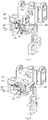
Fig. 1 is a structural schematic diagram of the invention with one terminal. -
Fig. 2 is a structural schematic diagram of the invention with three terminals. -
Fig. 3 is a structural schematic diagram of a handle of the invention in a closed state. -
Fig. 4 is a structural schematic diagram of a handle of the invention in an intermediate state between an open state and the closed state. -
Fig. 5 is a structural schematic diagram of a handle of the invention in the open state. -
Fig. 6 is a structural schematic diagram of a current bar bracket of the invention. -
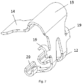
Fig. 7 is a structural schematic diagram of a spring of the invention. - Detailed embodiments in conjunction with the accompanying drawings are provided as followings for better understanding of the technical contents of the present invention.
- In the disclosure, various aspects of the invention are described with reference to the drawings, in which many illustrative embodiments are shown. Embodiments of the disclosure are not necessarily intended to include all the aspects of the present invention. It should be understood that a plurality of concepts and embodiments introduced above and detailed below can be implemented by any one of many manners, because the concepts and embodiments disclosed by the present invention are not limited to any way of implementation. In addition, some aspects of the present invention can be used alone, or in suitable combination with other aspects of the present invention.
- As shown in
Figs. 1-7 , a spring-connected grounding terminal for connecting to the grounding end for grounding of the conductive wires comprises acurrent bar bracket 5, on which at least oneterminal 6 is connected (the structural schematic diagrams of structures with oneterminal 6 and threeterminals 6 respectively connected on thecurrent bar bracket 5 are provided by the present invention), wherein at least one current bar connecting end 7 is disposed on thecurrent bar bracket 5, wherein each current bar connecting end 7 is connected to aterminal 6. When threeterminals 6 are connected on thecurrent bar bracket 5, the current bar connecting bar 7 is connected to a current bar bracket to form an integral part through acantilever 35. - As shown in
Fig. 1 , theterminal 6 comprises a housing, a spring 4, and ahandle 3, wherein the housing has an opening 8 to introduce a conductor, and aclamping slot 9 is disposed on the housing. - The housing is divided into a left housing 1 and a
right housing 2. Both the spring 4 and thehandle 3 are located inside the housing, in which afirst support bolt 10 and asecond support bolt 11 are disposed, wherein the spring 4 is sleeved inside thefirst support bolt 10, and the spring 4 has an open state and a closed state. Afirst rib 31 and asecond rib 32 are respectively disposed at corresponding positions of the left housing 1 and theright housing 2, wherein thefirst rib 31 is used to define positions of the support legs and thesecond rib 32 is used to define a position of asecond positioning spring 20. - As shown in
Fig. 7 , thespring 14 has, at one end, twosupport legs 12, which are connected to an executingarm 14 through aclamp arm 13, wherein the executingarm 14 is in a contact or separate state with respect to the conductive wire inserted into theterminal 6, theclamp arm 13 is rotatably installed inside thefirst support bolt 10, and thehandle 3 is bridged inside the twosupport legs 12. - The executing
arm 14 at the other end of the spring 4 mates with thecurrent bar bracket 5 to connect the conductive wires. - A first through
hole 15 is disposed on thehandle 3. The first throughhole 15 mates with thesecond support bolt 11. A hollowed-out portion 16 is disposed on thehandle 3. - A
first stopper 17 is disposed on thehandle 3. When thehandle 3 is in an open state, thefirst stopper 17 extends between the twosupport legs 12, and the front end of thehandle 3 is in contact with the twosupport legs 12 of the spring 4. - A
second stopper 18 is disposed on thehandle 3. When the spring 4 operates from an open state to a closed state, thesecond stopper 18 is in contact with the twosupport legs 12 and causes thesecond positioning spring 20 to be located inside the clampingedge 22 following the operational direction of thehandle 3. - A
groove 33 for accommodating thespring support legs 12 is disposed on thehandle 3 at its two side surfaces. - As shown in
Fig. 6 , the current bar connecting end 7 has abase portion 29 and a retainingarm 30 connected to the two side edges at the upper portion above thebase portion 29 and perpendicular to thebase portion 29, wherein the retainingarm 30 has atransition edge 21, a retainingedge 23, and a clampingedge 22 connecting thetransition edge 21 and the retainingedge 23, wherein the clampingedge 22 is in the shape of a circular arc, and a distance of the lowest point of the clampingedge 22 with respect to a bottom of the housing is smaller than a distance of thetransition edge 21 with respect to the bottom of the housing. - An
inclined portion 24 is disposed at thebase portion 29 of the current bar connecting end 7. An accommodation cavity opposite to the inclined portion is disposed on the housing, wherein theinclined portion 24 is connected to thebase portion 29 and is at a certain angle with respect to thebase portion 29. Theinclined portion 24 is located at the upper portion of the current bar connecting end 7. A plurality of evenly distributedconvex slots 25 are disposed at the side of thebase portion 29 that is in contact with the conductive wires. - The
current bar bracket 5 has a second throughhole 26 connected to the grounding end disposed therein. The positioning holes 34 are respectively dispose at two sides of the through hole. The positioning holes 34 mate with a convex portion disposed on the grounding end to secure the position of thecurrent bar bracket 5. Aconvex hull 27 extruding from a plane of thecurrent bar bracket 5 is disposed above the second throughhole 26 disposed on thecurrent bar bracket 5. Acurved surface 28 is disposed at the bottom of thecurrent bar bracket 5. Thecurved surface 28 curves in a same direction as the curving direction of theconvex hull 27. - When the spring 4 is in a closed state, the hollowed-
out portion 16 mates with theclamping slot 9, and the twosupport legs 12 of the spring 4 are in contact with the clampingedge 22. When the spring 4 is in an open state, the hollowed-out portion 16 is in a separate state with respect to theclamping slot 9, and the twosupport legs 12 of the spring 4 are in a separate state with respect to the current bar connecting end 7. - Two positioning springs are respectively disposed at the two side edges of the two
support legs 12 of the spring 4 that are in contact with the housing, wherein thefirst positioning spring 19 is located at a position where thesupport legs 12 are connected to theclamp arm 13 and thesecond positioning spring 20 is located at ends of thesupport legs 12. Thefirst positioning spring 19 is in a contact or separate state with respect to afirst rib 31 disposed on the housing. The spring 4 is in an open state when thefirst positioning spring 19 is in a contact state with respect to thefirst rib 31, and the spring 4 is in a closed state when thefirst positioning spring 19 is in a separate state with respect to thefirst rib 31. - The
second positioning spring 20 is in a contact or separate state with respect to asecond rib 32 disposed on the housing, wherein a height of thesecond rib 32 with respect to a bottom of the housing is the same as a height of thetransition edge 21 disposed on the current bar connecting end 7 with respect to the bottom of the housing. The spring 4 is in an open state when thesecond positioning spring 20 is in a contact state with respect to thesecond rib 32. The spring 4 is in a closed state and thesecond positioning spring 20 is located inside the clampingedge 22 disposed on the current bar connecting end 7 when thesecond positioning spring 20 is in a separate state with respect to thesecond rib 32. - The end of the
first positioning spring 19 and the end of thesecond positioning spring 20 curve inwards, i.e., curving towards the direction of the executingarm 14. - The operational principles of the spring-connected grounding terminal of the present invention are as follows:
The conductive wires are introduced through a conductor introducing opening 8 disposed on the housing. The conductive wires pass through the conductor introducing opening 8 to be in contact with thebase portion 29 of the current bar connecting end 7. The retainingarms 30 of the current bar connecting end 7 cause the conductive wires to be located between the two retainingarms 30, and at that time thehandle 3 is in an open state and the spring 4 is in an open state. When thehandle 3 swings from the open state to a closed state, the spring 4 moves from the open state to a closed state along thefirst support bolt 10 following swinging of thehandle 3; or the handle is opened again through an operation in a reverse direction. - As shown in
Fig. 5 , when the spring 4 is in an open state, thesecond positioning spring 20 is in contact with thesecond rib 32. At that time, thefirst stopper 17 extends between the twosupport legs 12, and thesecond stopper 18 is in a separate state with respect to thesupport legs 12 when thehandle 3 is operated to rotate. As the end of thetransition edge 21 disposed on the current bar connecting end 7 is at the same position as the end of thesecond rib 32, thesecond positioning spring 20 of the spring 4 slides along thetransition edge 21. During sliding, thefirst stopper 17 is in a separate state with respect to thesupport legs 12, the second stopper is in contact with thesupport legs 12 and applies a force to the spring 4, and the spring 4 enters the clampingedge 22 along thetransition edge 21. At that time, the hollowed-out portion 16 disposed on thehandle 3 is in contact with theclamping slot 9 disposed on the housing. As a distance of the lowest point of the clampingedge 22 with respect to a bottom of the housing is smaller than a distance of thetransition edge 21 with respect to the bottom of the housing, thesecond positioning spring 20 will not cause the spring 4 to move in a reverse direction due to its own elastic force. Therefore, the conductive wires are secured inside the housing. At that time, both the spring 4 and thehandle 3 are in a closed state. - With reference to
Figs. 3-5 , when thehandle 3 is operated along a reverse direction, thegroove 33 disposed on thehandle 3 squeezes thesecond positioning spring 20 to cause the spring 4 to move in the direction in which the handle is operated along thetransition edge 21, to cause the spring 4 to move to thetransition edge 21 along the clampingedge 22 and move to thesecond rib 22 along thetransition edge 21. When thesupport legs 12 are in contact with thefirst stopper 17, thehandle 3 is at a fully open position, and at that time, as thesupport legs 12 are fully inside thehandle 3 and the spring 4 is in a fully open state without elastic force, the spring 4 and thehandle 3 are secured in an open state. - It can be known from the above technical solution that the spring-connected grounding terminal of the present invention, in which at least one
terminal 6 is connected on acurrent bar bracket 5, enables a plurality ofterminals 6 to be connected on onecurrent bar bracket 5, increasing efficiency of connection. - The
terminal 6 comprises a housing, a spring 4, and ahandle 3. During connection of the conductive wires, the conductive wires can be reliably connected into theterminal 6 without aid of any tools, and it is not necessary to reserve relatively larger operational space inside the cabinet. - The
current bar bracket 5 has a through hole connected to the grounding end disposed therein. Positioning holes 34 are disposed at two sides of the through hole. The positioning holes 34 mate with the convex portion disposed on the grounding end to secure the position of thecurrent bar bracket 5. Mating of the though hole and the positioning holes 34 has thecurrent bar bracket 5 secured with a simple structure. - A
convex hull 27 extruding from a plane of thecurrent bar bracket 5 is disposed above the through hole disposed on thecurrent bar bracket 5. When the grounding end is not in planar contact with the contact end of thecurrent bar bracket 5, theconvex hull 27 can adjust the position of thecurrent bar bracket 5 to keep it co-planar. - A plurality of evenly distributed
convex slots 25 are disposed at a side of thebase portion 29 that is contact with the conductive wires. Theconvex slots 25 increase the friction between the conductive wires and thebase portion 29 of the current bar so that the conductive wires may not easily fall off theterminal 6. - Although the present invention is disclosed above with preferred embodiment, those embodiments are not to limit the present invention. One skilled in the art can make various alterations and modifications without departing the spirit and scope of the present invention. Thus, the protective scope of the present invention shall be determined by the claims.
Claims (8)
- A spring-connected grounding terminal for connecting to a grounding end for grounding of conductive wires, characterized in that the grounding terminal comprises a current bar bracket, on which at least one terminal is connected, wherein:at least one current bar connecting end is disposed on the current bar bracket, wherein each current bar connecting end is connected to a terminal;the terminal comprises a housing, a spring, and a handle, a first support bolt and a second support bolt are disposed inside the housing, wherein the spring is sleeved inside the first support bolt, and the spring has an open state and a closed state;a clamping slot is disposed on the housing;a first through hole, which mates with the second support bolt, is disposed on the handle; a hollowed-out portion is disposed on the handle;the spring has, at one end, two support legs, which are connected to an executing arm through a clamp arm, wherein the executing arm is in a contact or separate state with respect to the conductive wire inserted into the terminal, the clamp arm is rotatably installed inside the first support bolt, and the handle is bridged inside the two support legs;the executing arm at the other end of the spring mates with the current bar bracket to connect the conductive wires;the current bar connecting end has a base portion and a retaining arm connecting to the two side edges of an upper portion above the base portion and perpendicular to the base portion, wherein the retaining arm has a transition edge, a retaining edge, and a clamping edge connecting the transition edge and the retaining edge;when the spring is in a closed state, the hollowed-out portion mates with the clamping slot and the two support legs of the spring are in contact with the clamping edge; when the spring is in an open state, the hollowed-out portion is in a separate state with respect to the clamping slot and the two support legs of the spring are in a separate state with respect to the current bar connecting end;the current bar bracket has a second through hole connected to the grounding end disposed therein, and positioning holes are disposed at two sides of the second through hole, the positioning holes mating with a convex portion disposed on the grounding end to secure the position of the current bar bracket.
- The spring-connected grounding terminal according to claim 1, wherein an inclined edge is disposed at the base portion of the current bar connecting end, wherein the inclined edge is connected to the base portion and is at a certain angle with respect to the base portion.
- The spring-connected grounding terminal according to claim 1, wherein a plurality of evenly distributed convex slots are disposed at a side of the base portion that is in contact with the conductive wires.
- The spring-connected grounding terminal according to claim 1, wherein a convex hull extruding from a plane of the current bar bracket is disposed above the second through hole disposed on the current bar bracket.
- The spring-connected grounding terminal according to claim 4, wherein a curved surface, which curves in a same direction as the curving direction of the convex hull, is disposed at a bottom of the current bar bracket.
- The spring-connected grounding terminal according to claim 1, wherein a first stopper is disposed on the handle, when the handle is in an open state, the first stopper extends between the two support legs and the front end of the handle is in contact with the two support legs of the spring.
- The spring-connected grounding terminal according to claim 1, wherein two positioning springs are respectively disposed at two side edges of the two support legs of the spring that are in contact with the housing, wherein the first positioning spring is located at a position where the support legs are connected to the clamp arm, the second positioning spring is located at ends of the support legs, the first positioning spring is in a contact or separate state with respect to a first rib disposed on the housing, the spring is in an open state when the first positioning spring is in a contact state with respect to the first rib, the spring is in a closed state when the first positioning spring is in a separate state with respect to the first rib;
the second positioning spring is in a contact or separate state with respect to a second rib disposed on the housing, wherein a height of the second rib with respect to a bottom of the housing is the same as a height of the transition edge disposed on the current bar connecting end with respect to the bottom of the housing, the spring is in an open state when the second positioning spring is in a contact state with respect to the second rib, the spring is in a closed state and the second positioning spring is located inside the clamping edge disposed on the current bar connecting end when the second positioning spring is in a separate state with respect to the second rib. - The spring-connected grounding terminal according to claim 1, wherein the number of the current bar connecting ends is three.
Applications Claiming Priority (2)
| Application Number | Priority Date | Filing Date | Title |
|---|---|---|---|
| CN201810328773.0A CN108346887B (en) | 2018-04-13 | 2018-04-13 | Spring-connected ground terminal |
| PCT/CN2019/082374 WO2019196916A1 (en) | 2018-04-13 | 2019-04-12 | Spring-connected grounding terminal |
Publications (3)
| Publication Number | Publication Date |
|---|---|
| EP3780283A1 true EP3780283A1 (en) | 2021-02-17 |
| EP3780283A4 EP3780283A4 (en) | 2022-01-05 |
| EP3780283B1 EP3780283B1 (en) | 2024-06-05 |
Family
ID=62954909
Family Applications (1)
| Application Number | Title | Priority Date | Filing Date |
|---|---|---|---|
| EP19785093.6A Active EP3780283B1 (en) | 2018-04-13 | 2019-04-12 | Spring-connected grounding terminal |
Country Status (3)
| Country | Link |
|---|---|
| EP (1) | EP3780283B1 (en) |
| CN (1) | CN108346887B (en) |
| WO (1) | WO2019196916A1 (en) |
Families Citing this family (3)
| Publication number | Priority date | Publication date | Assignee | Title |
|---|---|---|---|---|
| CN108346887B (en) * | 2018-04-13 | 2024-02-02 | 菲尼克斯亚太电气(南京)有限公司 | Spring-connected ground terminal |
| CN110943340B (en) * | 2019-12-25 | 2024-04-16 | 浙江开控电气有限公司 | Quick wiring board device |
| CN118970528B (en) * | 2024-10-12 | 2024-12-13 | 康伟电子有限公司 | Series connection type wiring terminal |
Family Cites Families (8)
| Publication number | Priority date | Publication date | Assignee | Title |
|---|---|---|---|---|
| JP3355161B2 (en) * | 1999-11-09 | 2002-12-09 | ヤマハ株式会社 | Lever terminal |
| JP5428674B2 (en) * | 2009-09-08 | 2014-02-26 | 株式会社オートネットワーク技術研究所 | Ground connection device and wire harness including the same |
| DE102014114026B4 (en) * | 2014-09-26 | 2023-03-30 | Wago Verwaltungsgesellschaft Mbh | Conductor terminal and method of assembly |
| TWI603554B (en) * | 2014-12-31 | 2017-10-21 | Electrical connection terminals improved structure | |
| DE102015115612A1 (en) * | 2015-09-16 | 2017-03-16 | Phoenix Contact Gmbh & Co. Kg | Terminal for connecting an electrical conductor |
| CN205029030U (en) * | 2015-10-28 | 2016-02-10 | 四川华丰企业集团有限公司 | Structure of working a telephone switchboard fast |
| CN208062310U (en) * | 2018-04-13 | 2018-11-06 | 菲尼克斯亚太电气(南京)有限公司 | The ground terminal of spring connection |
| CN108346887B (en) * | 2018-04-13 | 2024-02-02 | 菲尼克斯亚太电气(南京)有限公司 | Spring-connected ground terminal |
-
2018
- 2018-04-13 CN CN201810328773.0A patent/CN108346887B/en active Active
-
2019
- 2019-04-12 WO PCT/CN2019/082374 patent/WO2019196916A1/en not_active Ceased
- 2019-04-12 EP EP19785093.6A patent/EP3780283B1/en active Active
Also Published As
| Publication number | Publication date |
|---|---|
| EP3780283B1 (en) | 2024-06-05 |
| WO2019196916A1 (en) | 2019-10-17 |
| EP3780283A4 (en) | 2022-01-05 |
| CN108346887B (en) | 2024-02-02 |
| CN108346887A (en) | 2018-07-31 |
Similar Documents
| Publication | Publication Date | Title |
|---|---|---|
| US20210057859A1 (en) | Combination outlet and power distribution unit incorporating the same | |
| EP3780283B1 (en) | Spring-connected grounding terminal | |
| US10939576B2 (en) | Power connector assembly for a communication system | |
| JP3203970U (en) | Clip-type connection box structure | |
| CN106972311A (en) | A kind of fast lock linear heat generation rate connector | |
| CN208955335U (en) | Back panel connector | |
| JP6472318B2 (en) | Terminal box and solar cell module | |
| US10903603B2 (en) | Electrical connector | |
| CN112003056B (en) | Socket and plug assembly convenient to insert and long in service life | |
| US3019406A (en) | Wiring device with wire gripping electrical connector | |
| CN208062310U (en) | The ground terminal of spring connection | |
| CN216120987U (en) | Connector supporting structure | |
| CN105655818A (en) | Fuse assembly supporting hot plugging and connector | |
| CN207149840U (en) | Socket with buffer structure | |
| CN104981950B (en) | Many cable connectors | |
| CN210326244U (en) | Socket and electronic device | |
| CN210052650U (en) | Voltage-sharing cover and switch assembly comprising same | |
| US10714873B2 (en) | Plug with protective conductor bridge | |
| CN208478723U (en) | electrical connector | |
| US3729612A (en) | Switch mechanism including quick detachable electrical connector means | |
| US20260058384A1 (en) | Connector assembly and system for installing a printed circuit board of a circuit breaker | |
| CN223109403U (en) | Power rails and rail sockets | |
| CN217281642U (en) | Special grounding wire conductive end device for switch cabinet | |
| CN222601506U (en) | Small-size dustproof line is to board | |
| CN212570894U (en) | Plug-in wiring terminal of circuit breaker |
Legal Events
| Date | Code | Title | Description |
|---|---|---|---|
| STAA | Information on the status of an ep patent application or granted ep patent |
Free format text: STATUS: THE INTERNATIONAL PUBLICATION HAS BEEN MADE |
|
| PUAI | Public reference made under article 153(3) epc to a published international application that has entered the european phase |
Free format text: ORIGINAL CODE: 0009012 |
|
| STAA | Information on the status of an ep patent application or granted ep patent |
Free format text: STATUS: REQUEST FOR EXAMINATION WAS MADE |
|
| 17P | Request for examination filed |
Effective date: 20201030 |
|
| AK | Designated contracting states |
Kind code of ref document: A1 Designated state(s): AL AT BE BG CH CY CZ DE DK EE ES FI FR GB GR HR HU IE IS IT LI LT LU LV MC MK MT NL NO PL PT RO RS SE SI SK SM TR |
|
| AX | Request for extension of the european patent |
Extension state: BA ME |
|
| DAV | Request for validation of the european patent (deleted) | ||
| DAX | Request for extension of the european patent (deleted) | ||
| REG | Reference to a national code |
Ref country code: DE Ref legal event code: R079 Ipc: H01R0004480000 Ref country code: DE Ref legal event code: R079 Ref document number: 602019053284 Country of ref document: DE Free format text: PREVIOUS MAIN CLASS: H01R0013150000 Ipc: H01R0004480000 |
|
| A4 | Supplementary search report drawn up and despatched |
Effective date: 20211203 |
|
| RIC1 | Information provided on ipc code assigned before grant |
Ipc: H01R 31/08 20060101ALN20211129BHEP Ipc: H01R 4/64 20060101ALI20211129BHEP Ipc: H01R 4/48 20060101AFI20211129BHEP |
|
| P01 | Opt-out of the competence of the unified patent court (upc) registered |
Effective date: 20230525 |
|
| P02 | Opt-out of the competence of the unified patent court (upc) changed |
Effective date: 20230531 |
|
| GRAP | Despatch of communication of intention to grant a patent |
Free format text: ORIGINAL CODE: EPIDOSNIGR1 |
|
| STAA | Information on the status of an ep patent application or granted ep patent |
Free format text: STATUS: GRANT OF PATENT IS INTENDED |
|
| P02 | Opt-out of the competence of the unified patent court (upc) changed |
Effective date: 20231121 |
|
| INTG | Intention to grant announced |
Effective date: 20231215 |
|
| RIC1 | Information provided on ipc code assigned before grant |
Ipc: H01R 31/08 20060101ALN20231201BHEP Ipc: H01R 4/64 20060101ALI20231201BHEP Ipc: H01R 4/48 20060101AFI20231201BHEP |
|
| GRAS | Grant fee paid |
Free format text: ORIGINAL CODE: EPIDOSNIGR3 |
|
| GRAA | (expected) grant |
Free format text: ORIGINAL CODE: 0009210 |
|
| STAA | Information on the status of an ep patent application or granted ep patent |
Free format text: STATUS: THE PATENT HAS BEEN GRANTED |
|
| AK | Designated contracting states |
Kind code of ref document: B1 Designated state(s): AL AT BE BG CH CY CZ DE DK EE ES FI FR GB GR HR HU IE IS IT LI LT LU LV MC MK MT NL NO PL PT RO RS SE SI SK SM TR |
|
| REG | Reference to a national code |
Ref country code: CH Ref legal event code: EP |
|
| REG | Reference to a national code |
Ref country code: DE Ref legal event code: R096 Ref document number: 602019053284 Country of ref document: DE |
|
| REG | Reference to a national code |
Ref country code: IE Ref legal event code: FG4D |
|
| REG | Reference to a national code |
Ref country code: LT Ref legal event code: MG9D |
|
| PG25 | Lapsed in a contracting state [announced via postgrant information from national office to epo] |
Ref country code: BG Free format text: LAPSE BECAUSE OF FAILURE TO SUBMIT A TRANSLATION OF THE DESCRIPTION OR TO PAY THE FEE WITHIN THE PRESCRIBED TIME-LIMIT Effective date: 20240605 |
|
| REG | Reference to a national code |
Ref country code: NL Ref legal event code: MP Effective date: 20240605 |
|
| PG25 | Lapsed in a contracting state [announced via postgrant information from national office to epo] |
Ref country code: FI Free format text: LAPSE BECAUSE OF FAILURE TO SUBMIT A TRANSLATION OF THE DESCRIPTION OR TO PAY THE FEE WITHIN THE PRESCRIBED TIME-LIMIT Effective date: 20240605 Ref country code: HR Free format text: LAPSE BECAUSE OF FAILURE TO SUBMIT A TRANSLATION OF THE DESCRIPTION OR TO PAY THE FEE WITHIN THE PRESCRIBED TIME-LIMIT Effective date: 20240605 |
|
| PG25 | Lapsed in a contracting state [announced via postgrant information from national office to epo] |
Ref country code: GR Free format text: LAPSE BECAUSE OF FAILURE TO SUBMIT A TRANSLATION OF THE DESCRIPTION OR TO PAY THE FEE WITHIN THE PRESCRIBED TIME-LIMIT Effective date: 20240906 |
|
| PG25 | Lapsed in a contracting state [announced via postgrant information from national office to epo] |
Ref country code: ES Free format text: LAPSE BECAUSE OF FAILURE TO SUBMIT A TRANSLATION OF THE DESCRIPTION OR TO PAY THE FEE WITHIN THE PRESCRIBED TIME-LIMIT Effective date: 20240605 |
|
| PG25 | Lapsed in a contracting state [announced via postgrant information from national office to epo] |
Ref country code: LV Free format text: LAPSE BECAUSE OF FAILURE TO SUBMIT A TRANSLATION OF THE DESCRIPTION OR TO PAY THE FEE WITHIN THE PRESCRIBED TIME-LIMIT Effective date: 20240605 |
|
| PG25 | Lapsed in a contracting state [announced via postgrant information from national office to epo] |
Ref country code: NO Free format text: LAPSE BECAUSE OF FAILURE TO SUBMIT A TRANSLATION OF THE DESCRIPTION OR TO PAY THE FEE WITHIN THE PRESCRIBED TIME-LIMIT Effective date: 20240905 Ref country code: LV Free format text: LAPSE BECAUSE OF FAILURE TO SUBMIT A TRANSLATION OF THE DESCRIPTION OR TO PAY THE FEE WITHIN THE PRESCRIBED TIME-LIMIT Effective date: 20240605 Ref country code: HR Free format text: LAPSE BECAUSE OF FAILURE TO SUBMIT A TRANSLATION OF THE DESCRIPTION OR TO PAY THE FEE WITHIN THE PRESCRIBED TIME-LIMIT Effective date: 20240605 Ref country code: GR Free format text: LAPSE BECAUSE OF FAILURE TO SUBMIT A TRANSLATION OF THE DESCRIPTION OR TO PAY THE FEE WITHIN THE PRESCRIBED TIME-LIMIT Effective date: 20240906 Ref country code: FI Free format text: LAPSE BECAUSE OF FAILURE TO SUBMIT A TRANSLATION OF THE DESCRIPTION OR TO PAY THE FEE WITHIN THE PRESCRIBED TIME-LIMIT Effective date: 20240605 Ref country code: ES Free format text: LAPSE BECAUSE OF FAILURE TO SUBMIT A TRANSLATION OF THE DESCRIPTION OR TO PAY THE FEE WITHIN THE PRESCRIBED TIME-LIMIT Effective date: 20240605 Ref country code: BG Free format text: LAPSE BECAUSE OF FAILURE TO SUBMIT A TRANSLATION OF THE DESCRIPTION OR TO PAY THE FEE WITHIN THE PRESCRIBED TIME-LIMIT Effective date: 20240605 Ref country code: RS Free format text: LAPSE BECAUSE OF FAILURE TO SUBMIT A TRANSLATION OF THE DESCRIPTION OR TO PAY THE FEE WITHIN THE PRESCRIBED TIME-LIMIT Effective date: 20240905 |
|
| PG25 | Lapsed in a contracting state [announced via postgrant information from national office to epo] |
Ref country code: NL Free format text: LAPSE BECAUSE OF FAILURE TO SUBMIT A TRANSLATION OF THE DESCRIPTION OR TO PAY THE FEE WITHIN THE PRESCRIBED TIME-LIMIT Effective date: 20240605 |
|
| REG | Reference to a national code |
Ref country code: AT Ref legal event code: MK05 Ref document number: 1693142 Country of ref document: AT Kind code of ref document: T Effective date: 20240605 |
|
| PG25 | Lapsed in a contracting state [announced via postgrant information from national office to epo] |
Ref country code: NL Free format text: LAPSE BECAUSE OF FAILURE TO SUBMIT A TRANSLATION OF THE DESCRIPTION OR TO PAY THE FEE WITHIN THE PRESCRIBED TIME-LIMIT Effective date: 20240605 |
|
| PG25 | Lapsed in a contracting state [announced via postgrant information from national office to epo] |
Ref country code: PT Free format text: LAPSE BECAUSE OF FAILURE TO SUBMIT A TRANSLATION OF THE DESCRIPTION OR TO PAY THE FEE WITHIN THE PRESCRIBED TIME-LIMIT Effective date: 20241007 |
|
| PG25 | Lapsed in a contracting state [announced via postgrant information from national office to epo] |
Ref country code: PT Free format text: LAPSE BECAUSE OF FAILURE TO SUBMIT A TRANSLATION OF THE DESCRIPTION OR TO PAY THE FEE WITHIN THE PRESCRIBED TIME-LIMIT Effective date: 20241007 |
|
| PG25 | Lapsed in a contracting state [announced via postgrant information from national office to epo] |
Ref country code: PL Free format text: LAPSE BECAUSE OF FAILURE TO SUBMIT A TRANSLATION OF THE DESCRIPTION OR TO PAY THE FEE WITHIN THE PRESCRIBED TIME-LIMIT Effective date: 20240605 |
|
| PG25 | Lapsed in a contracting state [announced via postgrant information from national office to epo] |
Ref country code: EE Free format text: LAPSE BECAUSE OF FAILURE TO SUBMIT A TRANSLATION OF THE DESCRIPTION OR TO PAY THE FEE WITHIN THE PRESCRIBED TIME-LIMIT Effective date: 20240605 |
|
| PG25 | Lapsed in a contracting state [announced via postgrant information from national office to epo] |
Ref country code: AT Free format text: LAPSE BECAUSE OF FAILURE TO SUBMIT A TRANSLATION OF THE DESCRIPTION OR TO PAY THE FEE WITHIN THE PRESCRIBED TIME-LIMIT Effective date: 20240605 Ref country code: IS Free format text: LAPSE BECAUSE OF FAILURE TO SUBMIT A TRANSLATION OF THE DESCRIPTION OR TO PAY THE FEE WITHIN THE PRESCRIBED TIME-LIMIT Effective date: 20241005 |
|
| PG25 | Lapsed in a contracting state [announced via postgrant information from national office to epo] |
Ref country code: CZ Free format text: LAPSE BECAUSE OF FAILURE TO SUBMIT A TRANSLATION OF THE DESCRIPTION OR TO PAY THE FEE WITHIN THE PRESCRIBED TIME-LIMIT Effective date: 20240605 |
|
| PG25 | Lapsed in a contracting state [announced via postgrant information from national office to epo] |
Ref country code: SK Free format text: LAPSE BECAUSE OF FAILURE TO SUBMIT A TRANSLATION OF THE DESCRIPTION OR TO PAY THE FEE WITHIN THE PRESCRIBED TIME-LIMIT Effective date: 20240605 Ref country code: RO Free format text: LAPSE BECAUSE OF FAILURE TO SUBMIT A TRANSLATION OF THE DESCRIPTION OR TO PAY THE FEE WITHIN THE PRESCRIBED TIME-LIMIT Effective date: 20240605 |
|
| PG25 | Lapsed in a contracting state [announced via postgrant information from national office to epo] |
Ref country code: SM Free format text: LAPSE BECAUSE OF FAILURE TO SUBMIT A TRANSLATION OF THE DESCRIPTION OR TO PAY THE FEE WITHIN THE PRESCRIBED TIME-LIMIT Effective date: 20240605 |
|
| PG25 | Lapsed in a contracting state [announced via postgrant information from national office to epo] |
Ref country code: SM Free format text: LAPSE BECAUSE OF FAILURE TO SUBMIT A TRANSLATION OF THE DESCRIPTION OR TO PAY THE FEE WITHIN THE PRESCRIBED TIME-LIMIT Effective date: 20240605 Ref country code: SK Free format text: LAPSE BECAUSE OF FAILURE TO SUBMIT A TRANSLATION OF THE DESCRIPTION OR TO PAY THE FEE WITHIN THE PRESCRIBED TIME-LIMIT Effective date: 20240605 Ref country code: RO Free format text: LAPSE BECAUSE OF FAILURE TO SUBMIT A TRANSLATION OF THE DESCRIPTION OR TO PAY THE FEE WITHIN THE PRESCRIBED TIME-LIMIT Effective date: 20240605 Ref country code: PL Free format text: LAPSE BECAUSE OF FAILURE TO SUBMIT A TRANSLATION OF THE DESCRIPTION OR TO PAY THE FEE WITHIN THE PRESCRIBED TIME-LIMIT Effective date: 20240605 Ref country code: IS Free format text: LAPSE BECAUSE OF FAILURE TO SUBMIT A TRANSLATION OF THE DESCRIPTION OR TO PAY THE FEE WITHIN THE PRESCRIBED TIME-LIMIT Effective date: 20241005 Ref country code: EE Free format text: LAPSE BECAUSE OF FAILURE TO SUBMIT A TRANSLATION OF THE DESCRIPTION OR TO PAY THE FEE WITHIN THE PRESCRIBED TIME-LIMIT Effective date: 20240605 Ref country code: CZ Free format text: LAPSE BECAUSE OF FAILURE TO SUBMIT A TRANSLATION OF THE DESCRIPTION OR TO PAY THE FEE WITHIN THE PRESCRIBED TIME-LIMIT Effective date: 20240605 Ref country code: AT Free format text: LAPSE BECAUSE OF FAILURE TO SUBMIT A TRANSLATION OF THE DESCRIPTION OR TO PAY THE FEE WITHIN THE PRESCRIBED TIME-LIMIT Effective date: 20240605 |
|
| PG25 | Lapsed in a contracting state [announced via postgrant information from national office to epo] |
Ref country code: IT Free format text: LAPSE BECAUSE OF FAILURE TO SUBMIT A TRANSLATION OF THE DESCRIPTION OR TO PAY THE FEE WITHIN THE PRESCRIBED TIME-LIMIT Effective date: 20240605 |
|
| REG | Reference to a national code |
Ref country code: DE Ref legal event code: R097 Ref document number: 602019053284 Country of ref document: DE |
|
| PLBE | No opposition filed within time limit |
Free format text: ORIGINAL CODE: 0009261 |
|
| STAA | Information on the status of an ep patent application or granted ep patent |
Free format text: STATUS: NO OPPOSITION FILED WITHIN TIME LIMIT |
|
| PG25 | Lapsed in a contracting state [announced via postgrant information from national office to epo] |
Ref country code: DK Free format text: LAPSE BECAUSE OF FAILURE TO SUBMIT A TRANSLATION OF THE DESCRIPTION OR TO PAY THE FEE WITHIN THE PRESCRIBED TIME-LIMIT Effective date: 20240605 |
|
| 26N | No opposition filed |
Effective date: 20250306 |
|
| PGFP | Annual fee paid to national office [announced via postgrant information from national office to epo] |
Ref country code: DE Payment date: 20250422 Year of fee payment: 7 |
|
| PG25 | Lapsed in a contracting state [announced via postgrant information from national office to epo] |
Ref country code: SE Free format text: LAPSE BECAUSE OF FAILURE TO SUBMIT A TRANSLATION OF THE DESCRIPTION OR TO PAY THE FEE WITHIN THE PRESCRIBED TIME-LIMIT Effective date: 20240605 |
|
| REG | Reference to a national code |
Ref country code: CH Ref legal event code: H13 Free format text: ST27 STATUS EVENT CODE: U-0-0-H10-H13 (AS PROVIDED BY THE NATIONAL OFFICE) Effective date: 20251125 |
|
| PG25 | Lapsed in a contracting state [announced via postgrant information from national office to epo] |
Ref country code: LU Free format text: LAPSE BECAUSE OF NON-PAYMENT OF DUE FEES Effective date: 20250412 |
|
| PG25 | Lapsed in a contracting state [announced via postgrant information from national office to epo] |
Ref country code: MC Free format text: LAPSE BECAUSE OF FAILURE TO SUBMIT A TRANSLATION OF THE DESCRIPTION OR TO PAY THE FEE WITHIN THE PRESCRIBED TIME-LIMIT Effective date: 20240605 |
|
| GBPC | Gb: european patent ceased through non-payment of renewal fee |
Effective date: 20250412 |
|
| REG | Reference to a national code |
Ref country code: BE Ref legal event code: MM Effective date: 20250430 |
|
| PG25 | Lapsed in a contracting state [announced via postgrant information from national office to epo] |
Ref country code: GB Free format text: LAPSE BECAUSE OF NON-PAYMENT OF DUE FEES Effective date: 20250412 |
|
| PG25 | Lapsed in a contracting state [announced via postgrant information from national office to epo] |
Ref country code: FR Free format text: LAPSE BECAUSE OF NON-PAYMENT OF DUE FEES Effective date: 20250430 |
|
| PG25 | Lapsed in a contracting state [announced via postgrant information from national office to epo] |
Ref country code: BE Free format text: LAPSE BECAUSE OF NON-PAYMENT OF DUE FEES Effective date: 20250430 |
|
| PG25 | Lapsed in a contracting state [announced via postgrant information from national office to epo] |
Ref country code: CH Free format text: LAPSE BECAUSE OF NON-PAYMENT OF DUE FEES Effective date: 20250430 |
|
| PG25 | Lapsed in a contracting state [announced via postgrant information from national office to epo] |
Ref country code: IE Free format text: LAPSE BECAUSE OF NON-PAYMENT OF DUE FEES Effective date: 20250412 |