EP3780274A1 - An array antenna arrangement - Google Patents
An array antenna arrangement Download PDFInfo
- Publication number
- EP3780274A1 EP3780274A1 EP19191491.0A EP19191491A EP3780274A1 EP 3780274 A1 EP3780274 A1 EP 3780274A1 EP 19191491 A EP19191491 A EP 19191491A EP 3780274 A1 EP3780274 A1 EP 3780274A1
- Authority
- EP
- European Patent Office
- Prior art keywords
- antenna
- array antenna
- arrangement
- array
- amplifier
- Prior art date
- Legal status (The legal status is an assumption and is not a legal conclusion. Google has not performed a legal analysis and makes no representation as to the accuracy of the status listed.)
- Granted
Links
Images


Classifications
-
- H—ELECTRICITY
- H01—ELECTRIC ELEMENTS
- H01Q—ANTENNAS, i.e. RADIO AERIALS
- H01Q3/00—Arrangements for changing or varying the orientation or the shape of the directional pattern of the waves radiated from an antenna or antenna system
- H01Q3/26—Arrangements for changing or varying the orientation or the shape of the directional pattern of the waves radiated from an antenna or antenna system varying the relative phase or relative amplitude of energisation between two or more active radiating elements; varying the distribution of energy across a radiating aperture
-
- H—ELECTRICITY
- H01—ELECTRIC ELEMENTS
- H01Q—ANTENNAS, i.e. RADIO AERIALS
- H01Q21/00—Antenna arrays or systems
- H01Q21/0006—Particular feeding systems
-
- H—ELECTRICITY
- H01—ELECTRIC ELEMENTS
- H01Q—ANTENNAS, i.e. RADIO AERIALS
- H01Q21/00—Antenna arrays or systems
- H01Q21/06—Arrays of individually energised antenna units similarly polarised and spaced apart
- H01Q21/061—Two dimensional planar arrays
- H01Q21/065—Patch antenna array
-
- H—ELECTRICITY
- H01—ELECTRIC ELEMENTS
- H01Q—ANTENNAS, i.e. RADIO AERIALS
- H01Q21/00—Antenna arrays or systems
- H01Q21/06—Arrays of individually energised antenna units similarly polarised and spaced apart
- H01Q21/08—Arrays of individually energised antenna units similarly polarised and spaced apart the units being spaced along or adjacent to a rectilinear path
-
- H—ELECTRICITY
- H01—ELECTRIC ELEMENTS
- H01Q—ANTENNAS, i.e. RADIO AERIALS
- H01Q1/00—Details of, or arrangements associated with, antennas
- H01Q1/27—Adaptation for use in or on movable bodies
- H01Q1/32—Adaptation for use in or on road or rail vehicles
- H01Q1/3208—Adaptation for use in or on road or rail vehicles characterised by the application wherein the antenna is used
- H01Q1/3233—Adaptation for use in or on road or rail vehicles characterised by the application wherein the antenna is used particular used as part of a sensor or in a security system, e.g. for automotive radar, navigation systems
Definitions
- the present disclosure relates to an array antenna arrangement that comprises at least two array antennas and at least two amplifier arrangement.
- Each array antenna has a corresponding antenna aperture
- each amplifier arrangement comprises a corresponding power amplifier and a corresponding phase shifter device.
- radar transceivers that are arranged for generating radar signals that are transmitted in a transmitter, reflected and received in a receiver.
- the radar signals may for example be in the form of FMCW (Frequency Modulated Continuous Wave) signals.
- vehicle radar systems For reception and transmission of such signals, vehicle radar systems comprises radar antennas for both reception and transmission, where these antennas are formed in many ways. Radar antennas are normally arranged to perform scanning in an azimuth direction, for example by means of digital beamforming. This means that in the azimuth plane, a broad antenna beam pattern illuminating the entire angular area of interest has to be radiated.
- the antenna beam pattern is focused into a narrow antenna beam pattern, such that the radiated energy is maximized towards the horizon. This provides maximum range.
- Vehicle radar systems will be used increasingly for highly autonomous driving and should become more and more sensitive to small objects, or objects with low reflectivity such as bicycles and motorbikes.
- vehicle radar systems can detect objects at increased distances, typically at non-zero azimuth angles, and also see near roadside features which may be at non-zero elevation angles.
- An increased range requires an improved antenna arrangement; one known method is to increase the length of the transmission antenna which, however, this has the effect of narrowing the pattern in elevation. Another known method is simultaneous transmission from two RF amplifiers feeding two side-by-side antennas. However this produces nulls in the azimuth pattern due to cancellation.
- the object of the present disclosure is thus to provide an improved antenna arrangement according to the above.
- an array antenna arrangement that comprises at least two array antennas and at least two amplifier arrangement.
- Each array antenna has a corresponding antenna aperture
- each amplifier arrangement comprises a corresponding power amplifier and a corresponding phase shifter device.
- a first amplifier arrangement is connected to a first array antenna having a first antenna aperture
- a second amplifier arrangement is connected to a second array antenna having a second antenna aperture.
- the first antenna aperture has a size that differs from a size of the second antenna aperture.
- Such a combined beam pattern can cover both distant and close-in targets with only one transmission mode, saving computational resources and silicon size.
- At least one array antenna comprises at least two linear arrays.
- At least two linear arrays comprised in one array antenna have different lengths.
- the present disclosure is applicable for a large variety of array antenna configurations.
- the first array antenna is adapted to radiate a first antenna beam pattern and the second array antenna is adapted to radiate a second antenna beam pattern.
- the first antenna beam pattern has a first 3dB beamwidth and the second antenna beam pattern has a second 3dB beamwidth that falls below the first 3dB beamwidth.
- the at least two array antennas are adapted to radiate a common antenna beam pattern, where the amplifier arrangements either are preset for providing a certain predefined common antenna beam pattern, or are adjustable for providing an adjustable common antenna beam pattern.
- the phase shifter devices are adapted to provide signal phases that provide a desired radar illumination with null suppression and a desired elevation beamwidth.
- the power amplifiers are adapted to provide signal amplitudes that provide a desired radar illumination with null suppression and a desired elevation beamwidth.
- the array antenna arrangement comprises a control unit, where the amplifier arrangements are connected to the control unit that is adapted to control the phase shifter devices and/or the power amplifiers.
- At least one array antenna is either connected to ground or unconnected, left open.
- At least two array antennas are mutually vertically displaced by a certain displacement distance.
- Figure 1 schematically shows a side view a vehicle 1 that runs on a road 2 in a forward direction F with a certain vehicle velocity, where the vehicle 1 comprises a vehicle radar system 3 which is arranged to distinguish and/or resolve single targets from the surroundings by using a Doppler effect in a previously well-known manner, i.e. successive echoes from the same point are superimposed and identified by means of Doppler effect.
- the radar system 3 has a main field of view 10 that is aimed in a pointing direction P that extends more or less in the same direction as the forward direction F.
- the radar system 3 comprises a transmitter arrangement 4 which in turn comprises a signal generator 5 and a transmitter antenna arrangement 6.
- the vehicle radar system 3 further comprises a receiver arrangement 7, which in turn comprises a receiver 8 and a receiver antenna arrangement 9.
- FMCW Frequency Modulated Continuous Wave
- the radar system 3 also comprises a control unit 13 that may be regarded as a control unit arrangement that is in the form of one unit or several units that either co-operate or handle different tasks more or less independently.
- the control unit 13 is according to some aspects arranged to control the transmitter arrangement 4 and the receiver arrangement 7, and to process the received signals.
- the array antenna arrangement 20 comprises a first array antenna 21 with a first antenna aperture 25, a second array antenna 22 with a second antenna aperture 26, a first amplifier arrangement 23 and a second amplifier arrangement 24.
- the first amplifier arrangement 23 comprises a first power amplifier 27 and a first phase shifter device 29, and the second amplifier arrangement 24 comprises a second power amplifier 28 and a second phase shifter device 30.
- the first amplifier arrangement 23 is connected to the first array antenna 21 and the second amplifier arrangement 24 is connected to the second array antenna 22.
- the first antenna aperture 25 has a size that differs from a size of the second antenna aperture 26.
- the first antenna aperture 25 has a size that falls below the size of the second antenna aperture 26. This is due to the fact that the first array antenna 21 is shorter than the second array antenna 22, each array antenna 21, 22 being consisted by a respective linear array.
- the size of a antenna aperture corresponds to an area of an antenna aperture.
- the array antenna arrangement 20 comprises a control unit 61, where the amplifier arrangements 23, 24 are connected to the control unit 61 that is adapted to control the phase shifter devices 29, 30.
- the control unit 61 is adapted to control the power amplifiers 27, 28, either separately or in combination with the phase shifter devices 29, 30.
- the array antenna arrangement 31 comprises a first central array antenna 32 with a first antenna aperture 38, a second lateral array antenna 33 with a second antenna aperture 39, and a third lateral array antenna 34 with a third antenna aperture 40.
- the array antenna arrangement 31 further comprises a first amplifier arrangement 35 with a corresponding first power amplifier 41 and first phase shifter device 44, a second amplifier arrangement 36 with a corresponding second power amplifier 42 and second phase shifter device 45, and a third amplifier arrangement 37 with a corresponding third power amplifier 43 and third phase shifter device 46
- the first amplifier arrangement 35 is connected to the first array antenna 32
- the second amplifier arrangement 36 is connected to the second array antenna 33
- the third amplifier arrangement 37 is connected to the third array antenna 34.
- the second antenna aperture 39 and the third antenna aperture 40 are of the same size, a size that exceeds the size of the first antenna aperture 38.
- the two linear arrays 33A, 33B; 33A, 34B in each array antenna 33, 34 are of mutually different lengths.
- the second amplifier arrangement 36 is connected to the single linear arrays 33A, 33B of the second array antenna 33 via a first power divider 63
- the third amplifier arrangement 37 is connected to the single linear arrays 34A, 34B of the second array antenna 34 via a second power divider 64.
- the array antenna arrangement 31 comprises a control unit 62, where the amplifier arrangements 35, 36, 37 are connected to the control unit 62 that is adapted to control the phase shifter devices 44, 45, 46.
- the control unit 62 is adapted to control the power amplifiers 41, 42, 43, either separately or in combination with the phase shifter devices 44, 45, 46.
- Using different array antenna aperture sizes preferably in combination with controlling the amplifier arrangements 35, 36, 37 provides properties such as required directionality, elevation beamwidth and enabling avoiding nulls in a combined beam pattern, as will be discussed more in detail below.
- the first array antenna 32 is adapted to radiate a first azimuth antenna beam pattern 47 being fed at a corresponding first antenna port 68
- the second array antenna 33 is adapted to radiate a second azimuth antenna beam pattern 48 being fed at a corresponding second antenna port 69
- the third array antenna 34 is adapted to radiate a third azimuth antenna beam pattern 49 being fed at a corresponding third antenna port 70.
- the first azimuth antenna beam pattern 47 has a first 3dB beamwidth
- the second azimuth antenna beam pattern has 48 a second 3dB beamwidth
- the third azimuth antenna beam pattern 49 a third 3dB beamwidth that is the same as the second 3dB beamwidth.
- the first 3dB beamwidth exceeds the second 3dB beamwidth and the third 3dB beamwidth.
- the different 3dB beamwidths are due to the different sizes of the antenna apertures 38, 39, 40 as shown in Figure 4 .
- a combined azimuth antenna beam pattern 50 is formed from these antenna beam patterns 47, 48, 49 via the amplifier arrangements 35, 36, 37, where the combined azimuth antenna beam pattern 50 has a certain direction D for its maximum power.
- the combined azimuth antenna beam pattern 50 is formed by feeding corresponding beam ports 65, 66, 67 that are connected to the amplifier arrangements 35, 36, 37.
- a combined elevation antenna beam pattern 51 is formed from these antenna beam patterns 47, 48, 49.
- the array antennas 32, 33, 34 are adapted to radiate a combined antenna beam pattern 50, 51, where the amplifier arrangements 35, 36, 37 either are preset for providing a certain predefined common antenna beam pattern 50, 51, or adjustable by means of the control unit 62 for providing an adjustable common antenna beam pattern 50, 51.
- sensitivity can be increased and the transmission energy can be focused in certain directions.
- a desired transmission combined antenna beam pattern 50, 51 shape can be created. This is primarily in azimuth but also elevation.
- the array antenna arrangement 31 may comprise a combination of narrow elevation beam array antennas and wider beam array antennas which together will provide good distance performance and information from closer range objects.
- the amplitude output of the power amplifiers 41, 42, 43 can be varied, or the amplitude may be varied using the array antennas and power splitters 63, 64.
- the signal energy may according to some aspects be split unequally to the linear arrays 33A, 33B; 24A, 34B, where possible phase difference between a set of the linear arrays 33A, 33B; 24A, 34B can be set by the feeder lengths or the splitter design of the splitters 63, 64.
- power amplifier amplitude is varied, this may be performed either at a calibration stage at sensor end of line, or updated during operation based on monitoring of the amplitude of targets.
- the amplitude variation is provided by means of amplitude tapering in the antenna field, avoiding amplitude tapering as this reduces the efficiency.
- Similar properties can be obtained from corresponding antenna ports 84, 85 and beam ports 86, 87 in the first example with reference to Figure 3 as well. Similar properties can be obtained from corresponding antenna ports 84, 85 and beam ports 86, 87 for the following examples as well.
- the present disclosure relates to using a mix of longer and shorter array antennas 21, 22; 32, 33, 34 that provide differently sized antenna apertures 25, 26; 38, 39, 40 in an array antenna arrangement 20, 31 where at least one antenna aperture has a size that differs from the size of another antenna aperture.
- the array antennas 21, 22; 32, 33, 34 can be fed in parallel from separate power amplifier arrangements 23, 24; 35, 36, 37.
- a desired combined antenna beam pattern 50, 51 in azimuth and elevation can be obtained, providing an optimized radar illumination without nulls and with sufficient elevation beamwidth.
- this optimization may be performed using simulations or may be calibrated at end of line, e.g. in a chamber, where the phases, and possibly also amplitudes, can be adapted.
- the array antenna arrangement 51 comprises a first central array antenna 32 that is connected to a first amplifier arrangement 35 in the same way as described for the second example.
- a second lateral array antenna 53 with a second antenna aperture 57 there is a second lateral array antenna 53 with a second antenna aperture 57, and a third lateral array antenna 54 with a third antenna aperture 58.
- a second amplifier arrangement 36 is connected to the second lateral array antenna 53 and a third amplifier arrangement 37 is connected to the third lateral array antenna 54.
- the second lateral array antenna 53 and the third lateral array antenna 54 are single linear arrays, only comprising one line of antenna elements each. Between the second lateral array antenna 53 and the first central array antenna 32 there is a first parasitic array antenna 55, and between the third lateral array antenna 54 and the first central array antenna 32 there is a second parasitic array antenna 56. Each parasitic array antenna 55, 56 has a corresponding antenna aperture 59, 60.
- the parasitic array antennas 55, 56 are either connected to ground or unconnected, left open, and are intended to further enhance the combined antenna beam pattern. For illustrative reasons, the first parasitic array antenna 55 is shown unconnected, and the second parasitic array antenna 56 is shown connected to ground. Often only one of these alternatives is used.
- the array antenna arrangement 52 comprises a control unit 62 of the same kind as described previously.
- the array antenna arrangement 100 comprises a first four-column array antenna 101 with a first antenna aperture 102, a second single-column array antenna 103 with a second antenna aperture 104, and a third single-column array antenna 105 with a third antenna aperture 106.
- the array antenna arrangement 100 further comprises a corresponding amplifier arrangement 107, 108, 109 for each array antenna 101, 103, 105, each amplifier arrangement 107, 108, 109 comprising a corresponding power amplifier 110, 111, 112 and first phase shifter device 113, 114, 115 in a manner similar to the previous examples.
- the second antenna aperture 104 and the third antenna aperture 106 are of the same size, a size that falls below the size of the first antenna aperture 102.
- the first array antenna 32 is constituted by four single linear arrays 101A, 101B, 101C, 101D, each single linear array 101A, 101B, 101C, 101D having a number of antenna elements 116 that exceeds the number of antenna elements 117, 118 of any one of the second array antenna 103 and the third array antenna 105.
- the second array antenna 103 and the third array antenna 105 are furthermore mutually vertically displaced by a certain displacement distance dy.
- the second antenna aperture 104 and the third antenna aperture 106 can be of mutually different sizes.
- the four single linear arrays 101A, 101B, 101C, 101D of the first array antenna 101 are connected to a first beam port 121 via a first power divider 119, a first antenna port 120 and a first amplifier arrangement 107.
- the second array antenna 103 and the third array antenna 105 are connected to a corresponding beam port 122, 123 via a corresponding antenna port 124, 125 and amplifier arrangement 108, 109.
- the array antenna arrangement 100 comprises a control unit 162, where the amplifier arrangements 107, 108, 109 are connected to the control unit 162 that is adapted to control the phase shifter devices 113, 114, 115.
- the control unit 162 is adapted to control the power amplifiers 110, 111, 112, either separately or in combination with the phase shifter devices 113, 114, 115.
- the array antenna arrangement 200 comprises a first two-column array antenna 201 with a first antenna aperture 202, a second two-column array antenna 203 with a second antenna aperture 204, and a third single-column array antenna 205 with a third antenna aperture 206.
- the array antenna arrangement 200 further comprises a corresponding amplifier arrangement 207, 208, 209 for each array antenna 201, 203, 205, each amplifier arrangement 207, 208, 209 comprising a corresponding power amplifier 210, 211, 212 and first phase shifter device 213, 214, 215 in a manner similar to the previous examples.
- the first antenna aperture 202 and the second antenna aperture 204 are of the same size, a size that exceeds the size of the third antenna aperture 206.
- the four single linear arrays 201A, 201B; 203A, 203B of the first array antenna 201 and the second array antenna 203 are connected to a corresponding beam port 221, 222 via a corresponding power divider 219, 220, a corresponding antenna port 223, 224 and a corresponding amplifier arrangement 207, 208.
- the third array antenna 205 is connected to a corresponding beam port 225 via a corresponding antenna port 226 and amplifier arrangement 209.
- the array antenna arrangement 200 comprises a control unit 262, where the amplifier arrangements 207, 208, 209 are connected to the control unit 262 that is adapted to control the phase shifter devices 213, 214, 215.
- the control unit 262 is adapted to control the power amplifiers 210, 211, 212, either separately or in combination with the phase shifter devices 213, 214, 215.
- first parasitic array antenna 255 at one side and a second parasitic array antenna 256 at another side such that the array antennas 201, 203, 205 are positioned between the parasitic array antennas 255, 256.
- Each parasitic array antenna 255, 256 has a corresponding antenna aperture 259, 260.
- the first parasitic array antenna 255 has a first parasitic antenna aperture 259 and the second parasitic array antenna 256 has a second parasitic antenna aperture 260 that has a size that falls below the size of the first parasitic antenna aperture 259. This is due to the fact that the first parasitic antenna 255 has a number of antenna elements 276 that exceeds the number of antenna elements 278 of the second parasitic array antenna 256.
- the parasitic array antennas 255, 256 are either connected to ground or unconnected, left open, and are intended to further enhance the combined antenna beam pattern. For illustrative reasons, the first parasitic array antenna 255 is shown unconnected, and the second parasitic array antenna 256 is shown connected to ground. Often only one of these alternatives is used.
- Parasitic array antennas as well as the other array antennas described, can thus have any suitable position in the array antenna arrangement in question, and can have different antenna aperture sizes as well as vertical positions.
- the horizontal spacing can also be varied such that a desired radiation pattern can be obtained.
- parasitic antenna arrays can of course be used without parasitic antenna arrays.
- the four identical single linear arrays 201A, 201B; 203A, 203B will have a fixed phase shift between them defined by the length of the traces. These may be the same phase or different for the two pairs.
- the fourth example is according to some aspects similar where there are four single linear arrays 101A, 101B; 103A, 103B that are identical and are fed from one antenna port 120.
- the second single-column array antenna 103 and the third single-column array antenna 105 are differently sized and fed directly at respective antenna ports 124, 125.
- the two pairs of identical single linear arrays 101A, 101B; 103A, 103B will have a fixed phase shift between them defined by the length of the traces. These may be the same phase or different for the two pairs.
- the present disclosure relates to using a mix of longer and shorter array antennas that provide differently sized antenna apertures in an array antenna arrangement where at least one antenna aperture has a size that differs from the size of another antenna aperture.
- the array antennas can according to some aspects be fed in parallel from separate power amplifier arrangements. By optimizing the phase, and possibly also the amplitude of the signal from each power amplifier arrangement, a desired combined antenna beam pattern in azimuth and elevation can be obtained, providing an optimized radar illumination without nulls and with sufficient elevation beamwidth.
- each array antenna comprises at least one row of antenna elements.
- Each array antenna, also each parasitic array antenna, is thus either one-dimensional or two-dimensional.
- the array antennas are in the form of microstrip antennas, where there are structures that have been etched from an initial copper layer on a dielectric material in a well-known-manner, for examples series-fed patches 71, 72; 73, 74, 75; 76, 77, 78, 79; 116, 117, 118; 216, 217, 218, 276, 278 (one patch schematically indicated for each array antenna in Figure 3 , Figure 4 and Figure 8 ).
- a linear array of series-fed patches are normally designed as a string of patches that are interconnected and fed at an antenna port that serves as a feeding point. The size of the patches may taper along the length of the linear array to form the elevation beam pattern.
- the transmitter arrangement 4 is adapted to transmit a block of FMCW ramps, or radar chirps, in rapid succession followed by a processing time.
- the transmission phases within such a block of radar chirps is changed (modulated) in order to allow them to be separated during processing.
- the RF phases are changed after chirp number 64, after chirp number 128 and after chirp number 192 based on an orthogonal coding scheme. This will enable separation of the channels such that an SAR (Synthetic Aperture Radar) or MIMO (Multiple Input Multiple Output) system is created.
- SAR Synthetic Aperture Radar
- MIMO Multiple Input Multiple Output
- antenna elements are of course conceivable, such as for example aperture-fed patches, dipole antenna elements and slot antennas.
- the array antennas can be made in other manners, such as for example by means of screen-printing or cutting in metal sheets or foils.
- phase shifters need not be controlled by a control unit, but can alternatively be manually controllable and even fixed, for example in the form of transmission delay lines.
- the array antenna arrangement according to the present disclosure can be used in a vehicle radar system, but can of course be used in any suitable context such as microwave links or similar.
- All sizes and lengths are in terms of wavelengths of an operational frequency, being constituted by electrical sizes and lengths.
- the combined beam can be created by combining the beam ports 86, 87; 65, 66, 67; 65, 82, 83 in any suitable way. For example applying a phase shift of 0° and 127° to the beam ports 86, 87 in Figure 3 will create a beam that is focused at 45° in the azimuth domain.
- the present disclosure employs multiple array antennas with their own amplifier circuits which may be of different physical sizes, where the different sized array antennas for example can be built up of different numbers of radiating elements coupled together, for the purpose of creating a defined radiation pattern in the azimuth and elevation domain. This can be tuned to optimize the directivity in the desired direction or directions as well as maintaining a lower but consistent directivity across a broad field of view with nulls of acceptable depth.
- the array antennas are of different sizes for the purposes of creating a steered beam of the desired radiation pattern. This may be accomplished through the additional use of software-defined phase shifters.
- the antennas may also be driven at non-equal powers.
- the resulting beam may be tuned, for example, to create high directionality in one or more direction, and also low directionality across a wide area with nulls of acceptable depth.
- the present disclosure relates to an array antenna arrangement 20, 31, 52, 100, 200 comprising at least two array antennas 21, 22; 32, 33, 34, 53, 54; 101, 103, 105; 201, 203, 205 and at least two amplifier arrangement 23, 24; 35, 36, 37; 107, 108, 109; 207, 208, 209.
- Each array antenna 21, 22; 32, 33, 34, 53, 54; 101, 103, 105; 201, 203, 205 has a corresponding antenna aperture 25, 26; 38, 39, 40, 57, 58; 102, 104, 106; 202, 204, 206, and each amplifier arrangement 23, 24; 35, 36, 37; 107, 108, 109; 207, 208, 209 comprises a corresponding power amplifier 27, 28; 41, 42, 43; 110, 111, 112; 210, 211, 212 and a corresponding phase shifter device 29, 30; 44, 45, 46; 113, 114, 115; 213, 214, 215.
- a first amplifier arrangement 23, 35, 107, 207 is connected to a first array antenna 21, 32, 101, 201 having a first antenna aperture 25, 38, 102, 202, and a second amplifier arrangement 24, 36, 108, 209 is connected to a second array antenna 22, 33, 53, 103, 205 having a second antenna aperture 26, 39, 57, 104, 206.
- the first antenna aperture 25, 38, 102, 202 has a size that differs from a size of the second antenna aperture 26, 39, 57, 104, 206.
- At least one array antenna 33, 34, 101, 201, 203 comprises at least two linear arrays 33A, 33B; 34A, 34B; 101A, 101B, 101C, 101D; 201A, 201B, 203A, 203B.
- At least two linear arrays 33A, 33B; 34A, 34B comprised in one array antenna 33, 34 have different lengths.
- the first array antenna 32 is adapted to radiate a first antenna beam pattern and the second array antenna 33 is adapted to radiate a second antenna beam pattern 48, where the first antenna beam pattern 47 has a first 3dB beamwidth and the second antenna beam pattern 48 has a second 3dB beamwidth that falls below the first 3dB beamwidth.
- the at least two array antennas 32, 33, 34 are adapted to radiate a common antenna beam pattern 50, 51, where the amplifier arrangements 35, 36, 37 either are preset for providing a certain predefined common antenna beam pattern 50, 51, or are adjustable for providing an adjustable common antenna beam pattern 50, 51.
- phase shifter devices 29, 30; 44, 45, 46; 113, 114, 115; 213, 214, 215 are adapted to provide signal phases that provide a desired radar illumination with null suppression and a desired elevation beamwidth.
- the power amplifiers 27, 28; 41, 42, 43; 110, 111, 112; 210, 211, 212 are adapted to provide signal amplitudes that provide a desired radar illumination with null suppression and a desired elevation beamwidth.
- the array antenna arrangement 20, 31, 52, 100, 200 comprises a control unit 61, 62, 162, 262, where the amplifier arrangements 23, 24; 35, 36, 37; 107, 108, 109; 207, 208, 209 are connected to the control unit 61, 62, 162, 262 that is adapted to control the phase shifter devices 29, 30; 44, 45, 46; 113, 114, 115; 213, 214, 215 and/or the power amplifiers 27, 28; 41, 42, 43; 110, 111, 112; 210, 211, 212.
- At least one array antenna 55, 56; 255, 256 either is connected to ground or unconnected, left open.
- At least two array antennas 103, 105 are mutually vertically displaced by a certain displacement distance dy.
Landscapes
- Variable-Direction Aerials And Aerial Arrays (AREA)
Abstract
Description
- The present disclosure relates to an array antenna arrangement that comprises at least two array antennas and at least two amplifier arrangement. Each array antenna has a corresponding antenna aperture, and each amplifier arrangement comprises a corresponding power amplifier and a corresponding phase shifter device.
- Many vehicle radar systems comprise radar transceivers that are arranged for generating radar signals that are transmitted in a transmitter, reflected and received in a receiver. The radar signals may for example be in the form of FMCW (Frequency Modulated Continuous Wave) signals.
- For reception and transmission of such signals, vehicle radar systems comprises radar antennas for both reception and transmission, where these antennas are formed in many ways. Radar antennas are normally arranged to perform scanning in an azimuth direction, for example by means of digital beamforming. This means that in the azimuth plane, a broad antenna beam pattern illuminating the entire angular area of interest has to be radiated.
- Orthogonal to the azimuth direction, in the elevation direction, the antenna beam pattern is focused into a narrow antenna beam pattern, such that the radiated energy is maximized towards the horizon. This provides maximum range.
- Vehicle radar systems will be used increasingly for highly autonomous driving and should become more and more sensitive to small objects, or objects with low reflectivity such as bicycles and motorbikes.
- It is desired that vehicle radar systems can detect objects at increased distances, typically at non-zero azimuth angles, and also see near roadside features which may be at non-zero elevation angles.
- An increased range requires an improved antenna arrangement; one known method is to increase the length of the transmission antenna which, however, this has the effect of narrowing the pattern in elevation. Another known method is simultaneous transmission from two RF amplifiers feeding two side-by-side antennas. However this produces nulls in the azimuth pattern due to cancellation.
- The object of the present disclosure is thus to provide an improved antenna arrangement according to the above.
- This object is achieved by means of an array antenna arrangement that comprises at least two array antennas and at least two amplifier arrangement. Each array antenna has a corresponding antenna aperture, and each amplifier arrangement comprises a corresponding power amplifier and a corresponding phase shifter device. A first amplifier arrangement is connected to a first array antenna having a first antenna aperture, and a second amplifier arrangement is connected to a second array antenna having a second antenna aperture. The first antenna aperture has a size that differs from a size of the second antenna aperture.
- This makes it possible to obtain a desired directionality, elevation beamwidth, and also makes it possible to avoid nulls in a combined beam pattern. Such a combined beam pattern can cover both distant and close-in targets with only one transmission mode, saving computational resources and silicon size.
- According to some aspects, at least one array antenna comprises at least two linear arrays.
- According to some aspects, at least two linear arrays comprised in one array antenna have different lengths.
- In other words, the present disclosure is applicable for a large variety of array antenna configurations.
- According to some aspects, the first array antenna is adapted to radiate a first antenna beam pattern and the second array antenna is adapted to radiate a second antenna beam pattern. The first antenna beam pattern has a first 3dB beamwidth and the second antenna beam pattern has a second 3dB beamwidth that falls below the first 3dB beamwidth.
- According to some aspects, the at least two array antennas are adapted to radiate a common antenna beam pattern, where the amplifier arrangements either are preset for providing a certain predefined common antenna beam pattern, or are adjustable for providing an adjustable common antenna beam pattern.
- According to some aspects, the phase shifter devices are adapted to provide signal phases that provide a desired radar illumination with null suppression and a desired elevation beamwidth.
- According to some aspects, the power amplifiers are adapted to provide signal amplitudes that provide a desired radar illumination with null suppression and a desired elevation beamwidth.
- According to some aspects, the array antenna arrangement comprises a control unit, where the amplifier arrangements are connected to the control unit that is adapted to control the phase shifter devices and/or the power amplifiers.
- This means that the beam pattern can be easily controlled.
- According to some aspects, at least one array antenna is either connected to ground or unconnected, left open.
- According to some aspects, at least two array antennas are mutually vertically displaced by a certain displacement distance.
- In this way, many different array antenna configurations are possible within the scope of the present disclosure.
- The present disclosure will now be described more in detail with reference to the appended drawings, where:
- Figure 1
- shows a schematic side view of a vehicle;
- Figure 2
- shows a schematic and simplified view of a radar system;
- Figure 3
- shows a schematic front view of a first example of an array antenna arrangement;
- Figure 4
- shows a schematic front view of a second example of an array antenna arrangement;
- Figure 5
- shows a schematic top view of an array antenna arrangement with separate azimuth antenna beam patterns;
- Figure 6
- shows a schematic top view of an array antenna arrangement with a combined azimuth antenna beam patterns;
- Figure 7
- shows a schematic side view of an array antenna arrangement with a combined elevation antenna beam patterns; and
- Figure 8
- shows a schematic front view of a third example of an array antenna arrangement;
- Figure 9
- shows a schematic front view of a fourth example of an array antenna arrangement; and
- Figure 10
- shows a schematic front view of a fifth example of an array antenna arrangement.
- The inventive concept will now be described more fully hereinafter with reference to the accompanying drawings, in which certain embodiments of the inventive concept are shown. This inventive concept may, however, be embodied in many different forms and should not be construed as limited to the embodiments set forth herein; rather, these embodiments are provided by way of example so that this disclosure will be thorough and complete, and will fully convey the scope of the inventive concept to those skilled in the art. Like numbers refer to like elements throughout the description.
-
Figure 1 schematically shows a side view avehicle 1 that runs on aroad 2 in a forward direction F with a certain vehicle velocity, where thevehicle 1 comprises avehicle radar system 3 which is arranged to distinguish and/or resolve single targets from the surroundings by using a Doppler effect in a previously well-known manner, i.e. successive echoes from the same point are superimposed and identified by means of Doppler effect. In this example, theradar system 3 has a main field ofview 10 that is aimed in a pointing direction P that extends more or less in the same direction as the forward direction F. - With reference also to
Figure 2 , showing a schematic and simplified view of theradar system 3, theradar system 3 comprises atransmitter arrangement 4 which in turn comprises asignal generator 5 and atransmitter antenna arrangement 6. Thevehicle radar system 3 further comprises areceiver arrangement 7, which in turn comprises areceiver 8 and areceiver antenna arrangement 9. In this example, FMCW (Frequency Modulated Continuous Wave) signals are transmitted in a previously well-known manner, such a signal comprising a plurality of FMCW ramps. Theradar system 3 also comprises acontrol unit 13 that may be regarded as a control unit arrangement that is in the form of one unit or several units that either co-operate or handle different tasks more or less independently. Thecontrol unit 13 is according to some aspects arranged to control thetransmitter arrangement 4 and thereceiver arrangement 7, and to process the received signals. - In the following, a
transmitter antenna arrangement 6 that is constituted by anarray antenna arrangement 20 will we discussed. - With reference to
Figure 3 , showing a front view of a first example of anarray antenna arrangement 20, thearray antenna arrangement 20 comprises afirst array antenna 21 with afirst antenna aperture 25, asecond array antenna 22 with asecond antenna aperture 26, afirst amplifier arrangement 23 and asecond amplifier arrangement 24. Thefirst amplifier arrangement 23 comprises afirst power amplifier 27 and a firstphase shifter device 29, and thesecond amplifier arrangement 24 comprises asecond power amplifier 28 and a secondphase shifter device 30. - The
first amplifier arrangement 23 is connected to thefirst array antenna 21 and thesecond amplifier arrangement 24 is connected to thesecond array antenna 22. - According to the present disclosure, the
first antenna aperture 25 has a size that differs from a size of thesecond antenna aperture 26. Here, thefirst antenna aperture 25 has a size that falls below the size of thesecond antenna aperture 26. This is due to the fact that thefirst array antenna 21 is shorter than thesecond array antenna 22, eacharray antenna - According to some aspects, the
array antenna arrangement 20 comprises acontrol unit 61, where theamplifier arrangements control unit 61 that is adapted to control thephase shifter devices control unit 61 is adapted to control thepower amplifiers phase shifter devices - Using different array antenna aperture sizes, preferably in combination with controlling the
amplifier arrangements - With reference to
Figure 4 , showing a front view of a second example of anarray antenna arrangement 31, thearray antenna arrangement 31 comprises a firstcentral array antenna 32 with afirst antenna aperture 38, a secondlateral array antenna 33 with asecond antenna aperture 39, and a thirdlateral array antenna 34 with athird antenna aperture 40. Thearray antenna arrangement 31 further comprises afirst amplifier arrangement 35 with a corresponding first power amplifier 41 and firstphase shifter device 44, asecond amplifier arrangement 36 with a correspondingsecond power amplifier 42 and secondphase shifter device 45, and athird amplifier arrangement 37 with a correspondingthird power amplifier 43 and thirdphase shifter device 46 - The
first amplifier arrangement 35 is connected to thefirst array antenna 32, thesecond amplifier arrangement 36 is connected to thesecond array antenna 33, and thethird amplifier arrangement 37 is connected to thethird array antenna 34. - In accordance with the present disclosure, there are antenna apertures of different sizes; the
second antenna aperture 39 and thethird antenna aperture 40 are of the same size, a size that exceeds the size of thefirst antenna aperture 38. This is in this example due to the fact that thefirst array antenna 32 is constituted by a single linear array, while thesecond array antenna 33 is constituted by two singlelinear arrays third array antenna 34 is constituted by two singlelinear arrays - According to some aspects, the two
linear arrays array antenna second amplifier arrangement 36 is connected to the singlelinear arrays second array antenna 33 via afirst power divider 63, and thethird amplifier arrangement 37 is connected to the singlelinear arrays second array antenna 34 via asecond power divider 64. - According to some aspects, the
array antenna arrangement 31 comprises acontrol unit 62, where theamplifier arrangements control unit 62 that is adapted to control thephase shifter devices control unit 62 is adapted to control thepower amplifiers phase shifter devices - Using different array antenna aperture sizes, preferably in combination with controlling the
amplifier arrangements - With maintained reference to
Figure 4 , as illustrated inFigure 5 , showing a top view of thearray antenna arrangement 31, thefirst array antenna 32 is adapted to radiate a first azimuthantenna beam pattern 47 being fed at a correspondingfirst antenna port 68, thesecond array antenna 33 is adapted to radiate a second azimuthantenna beam pattern 48 being fed at a correspondingsecond antenna port 69 and thethird array antenna 34 is adapted to radiate a third azimuthantenna beam pattern 49 being fed at a correspondingthird antenna port 70. - The first azimuth
antenna beam pattern 47 has a first 3dB beamwidth, the second azimuth antenna beam pattern has 48 a second 3dB beamwidth and the third azimuth antenna beam pattern 49 a third 3dB beamwidth that is the same as the second 3dB beamwidth. The first 3dB beamwidth exceeds the second 3dB beamwidth and the third 3dB beamwidth. The different 3dB beamwidths are due to the different sizes of theantenna apertures Figure 4 . - With reference also to
Figure 6 , a combined azimuthantenna beam pattern 50 is formed from theseantenna beam patterns amplifier arrangements antenna beam pattern 50 has a certain direction D for its maximum power. The combined azimuthantenna beam pattern 50 is formed by feeding correspondingbeam ports amplifier arrangements - Correspondingly, with reference also to
Figure 7 , a combined elevationantenna beam pattern 51 is formed from theseantenna beam patterns - This means that the
array antennas antenna beam pattern amplifier arrangements antenna beam pattern control unit 62 for providing an adjustable commonantenna beam pattern - According to some aspects, in this manner, by using three
power amplifiers - According to some aspects, by optimizing the array antennas, combined with varying the phase of the signal from the plurality of power amplifiers, a desired transmission combined
antenna beam pattern array antenna arrangement 31 may comprise a combination of narrow elevation beam array antennas and wider beam array antennas which together will provide good distance performance and information from closer range objects. - According to some aspects, in order to avoid nulls in the combined
antenna beam pattern power amplifiers power splitters linear arrays linear arrays splitters - If power amplifier amplitude is varied, this may be performed either at a calibration stage at sensor end of line, or updated during operation based on monitoring of the amplitude of targets.
- According to some aspects, the amplitude variation is provided by means of amplitude tapering in the antenna field, avoiding amplitude tapering as this reduces the efficiency.
- Similar properties can be obtained from corresponding
antenna ports beam ports Figure 3 as well. Similar properties can be obtained from correspondingantenna ports beam ports - According to some aspects, for all examples described and also generally, the present disclosure relates to using a mix of longer and
shorter array antennas sized antenna apertures array antenna arrangement array antennas power amplifier arrangements power amplifier arrangement antenna beam pattern - According to some aspects, this optimization may be performed using simulations or may be calibrated at end of line, e.g. in a chamber, where the phases, and possibly also amplitudes, can be adapted.
- With reference to
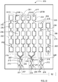
Figure 8 , showing a front view of a third example of anarray antenna arrangement 52, there is an arrangement similar to the one described with reference toFigure 4 . Thearray antenna arrangement 51 comprises a firstcentral array antenna 32 that is connected to afirst amplifier arrangement 35 in the same way as described for the second example. Here, there is a secondlateral array antenna 53 with asecond antenna aperture 57, and a thirdlateral array antenna 54 with athird antenna aperture 58. Asecond amplifier arrangement 36 is connected to the secondlateral array antenna 53 and athird amplifier arrangement 37 is connected to the thirdlateral array antenna 54. - Here, the second
lateral array antenna 53 and the thirdlateral array antenna 54 are single linear arrays, only comprising one line of antenna elements each. Between the secondlateral array antenna 53 and the firstcentral array antenna 32 there is a firstparasitic array antenna 55, and between the thirdlateral array antenna 54 and the firstcentral array antenna 32 there is a secondparasitic array antenna 56. Eachparasitic array antenna corresponding antenna aperture - The
parasitic array antennas parasitic array antenna 55 is shown unconnected, and the secondparasitic array antenna 56 is shown connected to ground. Often only one of these alternatives is used. - Corresponding
antenna ports beam ports array antenna arrangement 52 comprises acontrol unit 62 of the same kind as described previously. - Another example of an array antenna arrangement comprising parasitic array antennas will be disclosed later.
- In the following, three further examples of antenna arrangements according to the present disclosure will be disclosed.
- With reference to
Figure 9 , showing a front view of a fourth example of anarray antenna arrangement 100, thearray antenna arrangement 100 comprises a first four-column array antenna 101 with afirst antenna aperture 102, a second single-column array antenna 103 with asecond antenna aperture 104, and a third single-column array antenna 105 with athird antenna aperture 106. Thearray antenna arrangement 100 further comprises acorresponding amplifier arrangement array antenna amplifier arrangement corresponding power amplifier phase shifter device - In accordance with the present disclosure, there are antenna apertures of different sizes; the
second antenna aperture 104 and thethird antenna aperture 106 are of the same size, a size that falls below the size of thefirst antenna aperture 102. This is in this example due to the fact that thefirst array antenna 32 is constituted by four singlelinear arrays linear array antenna elements 116 that exceeds the number ofantenna elements second array antenna 103 and thethird array antenna 105. Thesecond array antenna 103 and thethird array antenna 105 are furthermore mutually vertically displaced by a certain displacement distance dy. According to some aspects, thesecond antenna aperture 104 and thethird antenna aperture 106 can be of mutually different sizes. - The four single
linear arrays first array antenna 101 are connected to afirst beam port 121 via afirst power divider 119, afirst antenna port 120 and afirst amplifier arrangement 107. Thesecond array antenna 103 and thethird array antenna 105 are connected to acorresponding beam port antenna port amplifier arrangement - According to some aspects, the
array antenna arrangement 100 comprises acontrol unit 162, where theamplifier arrangements control unit 162 that is adapted to control thephase shifter devices control unit 162 is adapted to control thepower amplifiers phase shifter devices - With reference to
Figure 10 , showing a front view of a fifth example of anarray antenna arrangement 200, thearray antenna arrangement 200 comprises a first two-column array antenna 201 with afirst antenna aperture 202, a second two-column array antenna 203 with asecond antenna aperture 204, and a third single-column array antenna 205 with athird antenna aperture 206. Thearray antenna arrangement 200 further comprises acorresponding amplifier arrangement array antenna amplifier arrangement corresponding power amplifier phase shifter device - In accordance with the present disclosure, there are antenna apertures of different sizes; the
first antenna aperture 202 and thesecond antenna aperture 204 are of the same size, a size that exceeds the size of thethird antenna aperture 206. This is in this example due to the fact that thefirst array antenna 201 and thesecond array antenna 203 both are constituted by two singlelinear arrays linear array antenna elements antenna elements 218 of thethird array antenna 205. - The four single
linear arrays first array antenna 201 and thesecond array antenna 203 are connected to acorresponding beam port corresponding power divider antenna port corresponding amplifier arrangement third array antenna 205 is connected to acorresponding beam port 225 via a correspondingantenna port 226 andamplifier arrangement 209. - According to some aspects, the
array antenna arrangement 200 comprises a control unit 262, where theamplifier arrangements phase shifter devices power amplifiers phase shifter devices - In a similar manner as described for the third example, there is a first
parasitic array antenna 255 at one side and a secondparasitic array antenna 256 at another side such that thearray antennas parasitic array antennas parasitic array antenna corresponding antenna aperture parasitic array antenna 255 has a firstparasitic antenna aperture 259 and the secondparasitic array antenna 256 has a secondparasitic antenna aperture 260 that has a size that falls below the size of the firstparasitic antenna aperture 259. this is due to the fact that the firstparasitic antenna 255 has a number ofantenna elements 276 that exceeds the number ofantenna elements 278 of the secondparasitic array antenna 256. - The
parasitic array antennas parasitic array antenna 255 is shown unconnected, and the secondparasitic array antenna 256 is shown connected to ground. Often only one of these alternatives is used. - Parasitic array antennas, as well as the other array antennas described, can thus have any suitable position in the array antenna arrangement in question, and can have different antenna aperture sizes as well as vertical positions. The horizontal spacing can also be varied such that a desired radiation pattern can be obtained.
- All examples disclosing parasitic antenna arrays can of course be used without parasitic antenna arrays. In that case, according to some aspects there are four single
linear arrays antenna ports column array antenna 205 is different and is fed directly at anantenna port 226. According to some further aspects, the four identical singlelinear arrays - The fourth example is according to some aspects similar where there are four single
linear arrays antenna port 120. The second single-column array antenna 103 and the third single-column array antenna 105 are differently sized and fed directly atrespective antenna ports linear arrays - As mentioned previously, the present disclosure relates to using a mix of longer and shorter array antennas that provide differently sized antenna apertures in an array antenna arrangement where at least one antenna aperture has a size that differs from the size of another antenna aperture. The array antennas can according to some aspects be fed in parallel from separate power amplifier arrangements. By optimizing the phase, and possibly also the amplitude of the signal from each power amplifier arrangement, a desired combined antenna beam pattern in azimuth and elevation can be obtained, providing an optimized radar illumination without nulls and with sufficient elevation beamwidth.
- Generally, there are at least two array antennas, where each array antenna comprises at least one row of antenna elements. Each array antenna, also each parasitic array antenna, is thus either one-dimensional or two-dimensional.
- According to some aspects, the array antennas are in the form of microstrip antennas, where there are structures that have been etched from an initial copper layer on a dielectric material in a well-known-manner, for examples series-fed
patches Figure 3 ,Figure 4 andFigure 8 ). A linear array of series-fed patches are normally designed as a string of patches that are interconnected and fed at an antenna port that serves as a feeding point. The size of the patches may taper along the length of the linear array to form the elevation beam pattern. - According to some aspects, with reference to
Figure 1 andFigure 9 , thetransmitter arrangement 4 is adapted to transmit a block of FMCW ramps, or radar chirps, in rapid succession followed by a processing time. According to some further aspects, the transmission phases within such a block of radar chirps is changed (modulated) in order to allow them to be separated during processing. - For example, for a block of 256 radar chirps, the RF phases are changed after
chirp number 64, after chirp number 128 and after chirp number 192 based on an orthogonal coding scheme. This will enable separation of the channels such that an SAR (Synthetic Aperture Radar) or MIMO (Multiple Input Multiple Output) system is created. - The present disclosure is not limited to the above, but may vary within the scope of the appended claims. For example, other antenna elements are of course conceivable, such as for example aperture-fed patches, dipole antenna elements and slot antennas. The array antennas can be made in other manners, such as for example by means of screen-printing or cutting in metal sheets or foils.
- Many different power combiner/divider and phase shifter arrangements are of course conceivable, the one shown only being one example. The phase shifters need not be controlled by a control unit, but can alternatively be manually controllable and even fixed, for example in the form of transmission delay lines.
- The array antenna arrangement according to the present disclosure can be used in a vehicle radar system, but can of course be used in any suitable context such as microwave links or similar.
- All sizes and lengths are in terms of wavelengths of an operational frequency, being constituted by electrical sizes and lengths.
- The combined beam can be created by combining the
beam ports beam ports Figure 3 will create a beam that is focused at 45° in the azimuth domain. - According to some aspects, the present disclosure employs multiple array antennas with their own amplifier circuits which may be of different physical sizes, where the different sized array antennas for example can be built up of different numbers of radiating elements coupled together, for the purpose of creating a defined radiation pattern in the azimuth and elevation domain. This can be tuned to optimize the directivity in the desired direction or directions as well as maintaining a lower but consistent directivity across a broad field of view with nulls of acceptable depth.
- According to some aspects, the array antennas are of different sizes for the purposes of creating a steered beam of the desired radiation pattern. This may be accomplished through the additional use of software-defined phase shifters. The antennas may also be driven at non-equal powers. The resulting beam may be tuned, for example, to create high directionality in one or more direction, and also low directionality across a wide area with nulls of acceptable depth.
- Generally, the present disclosure relates to an
array antenna arrangement array antennas amplifier arrangement array antenna corresponding antenna aperture amplifier arrangement corresponding power amplifier phase shifter device first amplifier arrangement first array antenna first antenna aperture second amplifier arrangement second array antenna second antenna aperture first antenna aperture second antenna aperture - According to some aspects, at least one
array antenna linear arrays - According to some aspects, at least two
linear arrays array antenna - According to some aspects, the
first array antenna 32 is adapted to radiate a first antenna beam pattern and thesecond array antenna 33 is adapted to radiate a secondantenna beam pattern 48, where the firstantenna beam pattern 47 has a first 3dB beamwidth and the secondantenna beam pattern 48 has a second 3dB beamwidth that falls below the first 3dB beamwidth. - According to some aspects, the at least two
array antennas antenna beam pattern amplifier arrangements antenna beam pattern antenna beam pattern - According to some aspects, the
phase shifter devices - According to some aspects, the
power amplifiers - According to some aspects, the
array antenna arrangement control unit amplifier arrangements control unit phase shifter devices power amplifiers - According to some aspects, at least one
array antenna - According to some aspects, at least two
array antennas
Claims (10)
- An array antenna arrangement (20, 31, 52, 100, 200) comprising at least two array antennas (21, 22; 32, 33, 34, 53, 54; 101, 103, 105; 201, 203, 205) and at least two amplifier arrangement (23, 24; 35, 36, 37; 107, 108, 109; 207, 208, 209), each array antenna (21, 22; 32, 33, 34, 53, 54; 101, 103, 105; 201, 203, 205) having a corresponding antenna aperture (25, 26; 38, 39, 40, 57, 58; 102, 104, 106; 202, 204, 206), and each amplifier arrangement (23, 24; 35, 36, 37; 107, 108, 109; 207, 208, 209) comprising a corresponding power amplifier (27, 28; 41, 42, 43; 110, 111, 112; 210, 211, 212) and a corresponding phase shifter device (29, 30; 44, 45, 46; 113, 114, 115; 213, 214, 215), where a first amplifier arrangement (23, 35, 107, 207) is connected to a first array antenna (21, 32, 101, 201) having a first antenna aperture (25, 38, 102, 202), and a second amplifier arrangement (24, 36, 108, 209) is connected to a second array antenna (22, 33, 53, 103, 205) having a second antenna aperture (26, 39, 57, 104, 206), characterized in that the first antenna aperture (25, 38, 102, 202) has a size that differs from a size of the second antenna aperture (26, 39, 57, 104, 206).
- The array antenna arrangement (31, 100, 200) according to claim 1, wherein at least one array antenna (33, 34, 101, 201, 203) comprises at least two linear arrays (33A, 33B; 34A, 34B; 101A, 101B, 101C, 101D; 201A, 201B, 203A, 203B).
- The array antenna arrangement (31) according to claim 2, wherein at least two linear arrays (33A, 33B; 34A, 34B) comprised in one array antenna (33, 34) have different lengths.
- The array antenna arrangement (31) according to any one of the previous claims, wherein the first array antenna (32) is adapted to radiate a first antenna beam pattern and the second array antenna (33) is adapted to radiate a second antenna beam pattern (48), where the first antenna beam pattern (47) has a first 3dB beamwidth and the second antenna beam pattern (48) has a second 3dB beamwidth that falls below the first 3dB beamwidth.
- The array antenna arrangement (31) according to any one of the previous claims, wherein the at least two array antennas (32, 33, 34) are adapted to radiate a common antenna beam pattern (50, 51), where the amplifier arrangements (35, 36, 37) either are preset for providing a certain predefined common antenna beam pattern (50, 51), or are adjustable for providing an adjustable common antenna beam pattern (50, 51).
- The array antenna arrangement (20, 31, 52, 100, 200) according to any one of the previous claims, wherein the phase shifter devices (29, 30; 44, 45, 46; 113, 114, 115; 213, 214, 215) are adapted to provide signal phases that provide a desired radar illumination with null suppression and a desired elevation beamwidth.
- The array antenna arrangement (20, 31, 52, 100, 200) according to any one of the previous claims, wherein the power amplifiers (27, 28; 41, 42, 43; 110, 111, 112; 210, 211, 212) are adapted to provide signal amplitudes that provide a desired radar illumination with null suppression and a desired elevation beamwidth.
- The array antenna arrangement (20, 31, 52, 100, 200) according to any one of the previous claims, wherein the array antenna arrangement (20, 31, 52, 100, 200) comprises a control unit (61, 62, 162, 262), where the amplifier arrangements (23, 24; 35, 36, 37; 107, 108, 109; 207, 208, 209) are connected to the control unit (61, 62, 162, 262) that is adapted to control the phase shifter devices (29, 30; 44, 45, 46; 113, 114, 115; 213, 214, 215) and/or the power amplifiers (27, 28; 41, 42, 43; 110, 111, 112; 210, 211, 212).
- The array antenna arrangement (52, 200) according to any one of the previous claims, wherein at least one array antenna (55, 56; 255, 256) either is connected to ground or unconnected, left open.
- The array antenna arrangement (100) according to any one of the previous claims, wherein at least two array antennas (103, 105) are mutually vertically displaced by a certain displacement distance (dy).
Priority Applications (1)
| Application Number | Priority Date | Filing Date | Title |
|---|---|---|---|
| EP19191491.0A EP3780274B1 (en) | 2019-08-13 | 2019-08-13 | An array antenna arrangement |
Applications Claiming Priority (1)
| Application Number | Priority Date | Filing Date | Title |
|---|---|---|---|
| EP19191491.0A EP3780274B1 (en) | 2019-08-13 | 2019-08-13 | An array antenna arrangement |
Publications (2)
| Publication Number | Publication Date |
|---|---|
| EP3780274A1 true EP3780274A1 (en) | 2021-02-17 |
| EP3780274B1 EP3780274B1 (en) | 2023-03-29 |
Family
ID=67620330
Family Applications (1)
| Application Number | Title | Priority Date | Filing Date |
|---|---|---|---|
| EP19191491.0A Active EP3780274B1 (en) | 2019-08-13 | 2019-08-13 | An array antenna arrangement |
Country Status (1)
| Country | Link |
|---|---|
| EP (1) | EP3780274B1 (en) |
Cited By (1)
| Publication number | Priority date | Publication date | Assignee | Title |
|---|---|---|---|---|
| CN115015933A (en) * | 2022-08-02 | 2022-09-06 | 中国人民解放军国防科技大学 | Forward-looking SAR imaging method and device based on light and small platform and radar |
Citations (3)
| Publication number | Priority date | Publication date | Assignee | Title |
|---|---|---|---|---|
| EP0970541A1 (en) * | 1997-03-24 | 2000-01-12 | Telefonaktiebolaget LM Ericsson (publ) | Integrated transmit/receive antenna with arbitrary utilisation of the antenna aperture |
| WO2018155439A1 (en) * | 2017-02-22 | 2018-08-30 | 株式会社デンソー | Radar device |
| US20190011532A1 (en) * | 2016-02-29 | 2019-01-10 | Robert Bosch Gmbh | Radar system including an antenna array for transmitting and receiving electromagnetic radiation |
-
2019
- 2019-08-13 EP EP19191491.0A patent/EP3780274B1/en active Active
Patent Citations (3)
| Publication number | Priority date | Publication date | Assignee | Title |
|---|---|---|---|---|
| EP0970541A1 (en) * | 1997-03-24 | 2000-01-12 | Telefonaktiebolaget LM Ericsson (publ) | Integrated transmit/receive antenna with arbitrary utilisation of the antenna aperture |
| US20190011532A1 (en) * | 2016-02-29 | 2019-01-10 | Robert Bosch Gmbh | Radar system including an antenna array for transmitting and receiving electromagnetic radiation |
| WO2018155439A1 (en) * | 2017-02-22 | 2018-08-30 | 株式会社デンソー | Radar device |
Non-Patent Citations (2)
| Title |
|---|
| KLAUS BAUR ET AL: "Beamforming concepts for angular measurements in azimuth and elevation with 77 GHz lens based radar sensors", MICROWAVE SYMPOSIUM DIGEST (MTT), 2011 IEEE MTT-S INTERNATIONAL, IEEE, 5 June 2011 (2011-06-05), pages 1 - 4, XP032006541, ISBN: 978-1-61284-754-2, DOI: 10.1109/MWSYM.2011.5972592 * |
| MILTON LIEN: "Count on Design Software for Millimeter-Wave Automotive Radar and Antenna System Development, Part 2 | Microwaves & RF", 1 February 2018 (2018-02-01), XP055659445, Retrieved from the Internet <URL:https://www.mwrf.com/technologies/software/article/21848959/count-on-design-software-for-millimeterwave-automotive-radar-and-antenna-system-development-part-2> [retrieved on 20200120] * |
Cited By (1)
| Publication number | Priority date | Publication date | Assignee | Title |
|---|---|---|---|---|
| CN115015933A (en) * | 2022-08-02 | 2022-09-06 | 中国人民解放军国防科技大学 | Forward-looking SAR imaging method and device based on light and small platform and radar |
Also Published As
| Publication number | Publication date |
|---|---|
| EP3780274B1 (en) | 2023-03-29 |
Similar Documents
| Publication | Publication Date | Title |
|---|---|---|
| CN106571536B (en) | MIMO antenna with pitch detection | |
| US11444377B2 (en) | Radiation pattern reconfigurable antenna | |
| JP6883592B2 (en) | Polarization phased array radar system and its operation method | |
| EP0618641B1 (en) | Ultra wideband phased array antenna | |
| US9379437B1 (en) | Continuous horn circular array antenna system | |
| US10897088B2 (en) | Leaky-wave slotted microstrip antenna | |
| JP2013083645A (en) | Transmit and receive phased array for automotive radar improvement | |
| US11041938B2 (en) | Radar apparatus | |
| US11515639B2 (en) | Method and apparatus for an active radiating and feed structure | |
| US11063372B2 (en) | Elementary antenna comprising a planar radiating device | |
| US20240222853A1 (en) | Vehicle radar sensor unit with increased vertical resolution | |
| JPH09284035A (en) | In-vehicle radar antenna device | |
| JPH06291535A (en) | Array antenna | |
| JP7098732B2 (en) | Radar system | |
| EP3780274B1 (en) | An array antenna arrangement | |
| RU2541888C1 (en) | Multibeam microwave linear antenna array and two-dimensional antenna array based thereon | |
| RU2297699C2 (en) | Phased array | |
| JP7817916B2 (en) | Electronic equipment and transmission/reception systems | |
| EP1729146A1 (en) | Direction finder antenna receiver system | |
| KR20250018714A (en) | Metamaterial Flat Lens-Combined 3-Dimensional Pointing Angle-Control by Switching Electromagnetic-Wave Source(PACbyEMSS) for Radar and Communication Beamforming Antennas Doing Away With Chip-Type Active Phase Shifters | |
| KR20250018707A (en) | Metamaterial Flat Lens-Combined Pointing Angle-Control by Switching Electromagnetic-Wave Source(PACbyEMSS) for Radr and Communication Beamforming Antennas Doing Away With Chip-Type Active Phase Shifters | |
| WO2021110947A1 (en) | Scanning antenna | |
| WO2019138037A1 (en) | Radar systems |
Legal Events
| Date | Code | Title | Description |
|---|---|---|---|
| PUAI | Public reference made under article 153(3) epc to a published international application that has entered the european phase |
Free format text: ORIGINAL CODE: 0009012 |
|
| STAA | Information on the status of an ep patent application or granted ep patent |
Free format text: STATUS: THE APPLICATION HAS BEEN PUBLISHED |
|
| AK | Designated contracting states |
Kind code of ref document: A1 Designated state(s): AL AT BE BG CH CY CZ DE DK EE ES FI FR GB GR HR HU IE IS IT LI LT LU LV MC MK MT NL NO PL PT RO RS SE SI SK SM TR |
|
| AX | Request for extension of the european patent |
Extension state: BA ME |
|
| STAA | Information on the status of an ep patent application or granted ep patent |
Free format text: STATUS: REQUEST FOR EXAMINATION WAS MADE |
|
| STAA | Information on the status of an ep patent application or granted ep patent |
Free format text: STATUS: EXAMINATION IS IN PROGRESS |
|
| 17P | Request for examination filed |
Effective date: 20210813 |
|
| RBV | Designated contracting states (corrected) |
Designated state(s): AL AT BE BG CH CY CZ DE DK EE ES FI FR GB GR HR HU IE IS IT LI LT LU LV MC MK MT NL NO PL PT RO RS SE SI SK SM TR |
|
| 17Q | First examination report despatched |
Effective date: 20210908 |
|
| RAP1 | Party data changed (applicant data changed or rights of an application transferred) |
Owner name: ARRIVER SOFTWARE AB |
|
| RIC1 | Information provided on ipc code assigned before grant |
Ipc: H01Q 1/32 20060101ALN20220822BHEP Ipc: H01Q 21/08 20060101ALI20220822BHEP Ipc: H01Q 21/06 20060101ALI20220822BHEP Ipc: H01Q 21/00 20060101ALI20220822BHEP Ipc: H01Q 3/26 20060101AFI20220822BHEP |
|
| GRAP | Despatch of communication of intention to grant a patent |
Free format text: ORIGINAL CODE: EPIDOSNIGR1 |
|
| STAA | Information on the status of an ep patent application or granted ep patent |
Free format text: STATUS: GRANT OF PATENT IS INTENDED |
|
| RIC1 | Information provided on ipc code assigned before grant |
Ipc: H01Q 1/32 20060101ALN20220926BHEP Ipc: H01Q 21/08 20060101ALI20220926BHEP Ipc: H01Q 21/06 20060101ALI20220926BHEP Ipc: H01Q 21/00 20060101ALI20220926BHEP Ipc: H01Q 3/26 20060101AFI20220926BHEP |
|
| INTG | Intention to grant announced |
Effective date: 20221019 |
|
| RIN1 | Information on inventor provided before grant (corrected) |
Inventor name: LEFEVRE, ANDREAS Inventor name: MARSCH, SEBASTIAN Inventor name: GOELZ, HANSJERG Inventor name: JENKINS, ALAN Inventor name: FUCHS, MARTIN Inventor name: NAINWAL, KRISHNAKANT Inventor name: MOSS, JONATHAN |
|
| GRAS | Grant fee paid |
Free format text: ORIGINAL CODE: EPIDOSNIGR3 |
|
| GRAA | (expected) grant |
Free format text: ORIGINAL CODE: 0009210 |
|
| STAA | Information on the status of an ep patent application or granted ep patent |
Free format text: STATUS: THE PATENT HAS BEEN GRANTED |
|
| AK | Designated contracting states |
Kind code of ref document: B1 Designated state(s): AL AT BE BG CH CY CZ DE DK EE ES FI FR GB GR HR HU IE IS IT LI LT LU LV MC MK MT NL NO PL PT RO RS SE SI SK SM TR |
|
| REG | Reference to a national code |
Ref country code: CH Ref legal event code: EP |
|
| REG | Reference to a national code |
Ref country code: DE Ref legal event code: R096 Ref document number: 602019026817 Country of ref document: DE |
|
| REG | Reference to a national code |
Ref country code: AT Ref legal event code: REF Ref document number: 1557319 Country of ref document: AT Kind code of ref document: T Effective date: 20230415 |
|
| REG | Reference to a national code |
Ref country code: IE Ref legal event code: FG4D |
|
| REG | Reference to a national code |
Ref country code: LT Ref legal event code: MG9D |
|
| PG25 | Lapsed in a contracting state [announced via postgrant information from national office to epo] |
Ref country code: RS Free format text: LAPSE BECAUSE OF FAILURE TO SUBMIT A TRANSLATION OF THE DESCRIPTION OR TO PAY THE FEE WITHIN THE PRESCRIBED TIME-LIMIT Effective date: 20230329 Ref country code: NO Free format text: LAPSE BECAUSE OF FAILURE TO SUBMIT A TRANSLATION OF THE DESCRIPTION OR TO PAY THE FEE WITHIN THE PRESCRIBED TIME-LIMIT Effective date: 20230629 Ref country code: LV Free format text: LAPSE BECAUSE OF FAILURE TO SUBMIT A TRANSLATION OF THE DESCRIPTION OR TO PAY THE FEE WITHIN THE PRESCRIBED TIME-LIMIT Effective date: 20230329 Ref country code: LT Free format text: LAPSE BECAUSE OF FAILURE TO SUBMIT A TRANSLATION OF THE DESCRIPTION OR TO PAY THE FEE WITHIN THE PRESCRIBED TIME-LIMIT Effective date: 20230329 Ref country code: HR Free format text: LAPSE BECAUSE OF FAILURE TO SUBMIT A TRANSLATION OF THE DESCRIPTION OR TO PAY THE FEE WITHIN THE PRESCRIBED TIME-LIMIT Effective date: 20230329 |
|
| REG | Reference to a national code |
Ref country code: NL Ref legal event code: MP Effective date: 20230329 |
|
| REG | Reference to a national code |
Ref country code: AT Ref legal event code: MK05 Ref document number: 1557319 Country of ref document: AT Kind code of ref document: T Effective date: 20230329 |
|
| PG25 | Lapsed in a contracting state [announced via postgrant information from national office to epo] |
Ref country code: SE Free format text: LAPSE BECAUSE OF FAILURE TO SUBMIT A TRANSLATION OF THE DESCRIPTION OR TO PAY THE FEE WITHIN THE PRESCRIBED TIME-LIMIT Effective date: 20230329 Ref country code: NL Free format text: LAPSE BECAUSE OF FAILURE TO SUBMIT A TRANSLATION OF THE DESCRIPTION OR TO PAY THE FEE WITHIN THE PRESCRIBED TIME-LIMIT Effective date: 20230329 Ref country code: GR Free format text: LAPSE BECAUSE OF FAILURE TO SUBMIT A TRANSLATION OF THE DESCRIPTION OR TO PAY THE FEE WITHIN THE PRESCRIBED TIME-LIMIT Effective date: 20230630 Ref country code: FI Free format text: LAPSE BECAUSE OF FAILURE TO SUBMIT A TRANSLATION OF THE DESCRIPTION OR TO PAY THE FEE WITHIN THE PRESCRIBED TIME-LIMIT Effective date: 20230329 |
|
| PG25 | Lapsed in a contracting state [announced via postgrant information from national office to epo] |
Ref country code: SM Free format text: LAPSE BECAUSE OF FAILURE TO SUBMIT A TRANSLATION OF THE DESCRIPTION OR TO PAY THE FEE WITHIN THE PRESCRIBED TIME-LIMIT Effective date: 20230329 Ref country code: RO Free format text: LAPSE BECAUSE OF FAILURE TO SUBMIT A TRANSLATION OF THE DESCRIPTION OR TO PAY THE FEE WITHIN THE PRESCRIBED TIME-LIMIT Effective date: 20230329 Ref country code: PT Free format text: LAPSE BECAUSE OF FAILURE TO SUBMIT A TRANSLATION OF THE DESCRIPTION OR TO PAY THE FEE WITHIN THE PRESCRIBED TIME-LIMIT Effective date: 20230731 Ref country code: ES Free format text: LAPSE BECAUSE OF FAILURE TO SUBMIT A TRANSLATION OF THE DESCRIPTION OR TO PAY THE FEE WITHIN THE PRESCRIBED TIME-LIMIT Effective date: 20230329 Ref country code: EE Free format text: LAPSE BECAUSE OF FAILURE TO SUBMIT A TRANSLATION OF THE DESCRIPTION OR TO PAY THE FEE WITHIN THE PRESCRIBED TIME-LIMIT Effective date: 20230329 Ref country code: AT Free format text: LAPSE BECAUSE OF FAILURE TO SUBMIT A TRANSLATION OF THE DESCRIPTION OR TO PAY THE FEE WITHIN THE PRESCRIBED TIME-LIMIT Effective date: 20230329 |
|
| PG25 | Lapsed in a contracting state [announced via postgrant information from national office to epo] |
Ref country code: SK Free format text: LAPSE BECAUSE OF FAILURE TO SUBMIT A TRANSLATION OF THE DESCRIPTION OR TO PAY THE FEE WITHIN THE PRESCRIBED TIME-LIMIT Effective date: 20230329 Ref country code: PL Free format text: LAPSE BECAUSE OF FAILURE TO SUBMIT A TRANSLATION OF THE DESCRIPTION OR TO PAY THE FEE WITHIN THE PRESCRIBED TIME-LIMIT Effective date: 20230329 Ref country code: IS Free format text: LAPSE BECAUSE OF FAILURE TO SUBMIT A TRANSLATION OF THE DESCRIPTION OR TO PAY THE FEE WITHIN THE PRESCRIBED TIME-LIMIT Effective date: 20230729 |
|
| REG | Reference to a national code |
Ref country code: DE Ref legal event code: R097 Ref document number: 602019026817 Country of ref document: DE |
|
| PG25 | Lapsed in a contracting state [announced via postgrant information from national office to epo] |
Ref country code: DK Free format text: LAPSE BECAUSE OF FAILURE TO SUBMIT A TRANSLATION OF THE DESCRIPTION OR TO PAY THE FEE WITHIN THE PRESCRIBED TIME-LIMIT Effective date: 20230329 Ref country code: CZ Free format text: LAPSE BECAUSE OF FAILURE TO SUBMIT A TRANSLATION OF THE DESCRIPTION OR TO PAY THE FEE WITHIN THE PRESCRIBED TIME-LIMIT Effective date: 20230329 |
|
| PLBE | No opposition filed within time limit |
Free format text: ORIGINAL CODE: 0009261 |
|
| STAA | Information on the status of an ep patent application or granted ep patent |
Free format text: STATUS: NO OPPOSITION FILED WITHIN TIME LIMIT |
|
| 26N | No opposition filed |
Effective date: 20240103 |
|
| PG25 | Lapsed in a contracting state [announced via postgrant information from national office to epo] |
Ref country code: MC Free format text: LAPSE BECAUSE OF FAILURE TO SUBMIT A TRANSLATION OF THE DESCRIPTION OR TO PAY THE FEE WITHIN THE PRESCRIBED TIME-LIMIT Effective date: 20230329 |
|
| REG | Reference to a national code |
Ref country code: CH Ref legal event code: PL |
|
| PG25 | Lapsed in a contracting state [announced via postgrant information from national office to epo] |
Ref country code: MC Free format text: LAPSE BECAUSE OF FAILURE TO SUBMIT A TRANSLATION OF THE DESCRIPTION OR TO PAY THE FEE WITHIN THE PRESCRIBED TIME-LIMIT Effective date: 20230329 |
|
| PG25 | Lapsed in a contracting state [announced via postgrant information from national office to epo] |
Ref country code: LU Free format text: LAPSE BECAUSE OF NON-PAYMENT OF DUE FEES Effective date: 20230813 |
|
| GBPC | Gb: european patent ceased through non-payment of renewal fee |
Effective date: 20230813 |
|
| PG25 | Lapsed in a contracting state [announced via postgrant information from national office to epo] |
Ref country code: LU Free format text: LAPSE BECAUSE OF NON-PAYMENT OF DUE FEES Effective date: 20230813 Ref country code: CH Free format text: LAPSE BECAUSE OF NON-PAYMENT OF DUE FEES Effective date: 20230831 |
|
| PG25 | Lapsed in a contracting state [announced via postgrant information from national office to epo] |
Ref country code: SI Free format text: LAPSE BECAUSE OF FAILURE TO SUBMIT A TRANSLATION OF THE DESCRIPTION OR TO PAY THE FEE WITHIN THE PRESCRIBED TIME-LIMIT Effective date: 20230329 |
|
| REG | Reference to a national code |
Ref country code: BE Ref legal event code: MM Effective date: 20230831 |
|
| REG | Reference to a national code |
Ref country code: IE Ref legal event code: MM4A |
|
| PG25 | Lapsed in a contracting state [announced via postgrant information from national office to epo] |
Ref country code: SI Free format text: LAPSE BECAUSE OF FAILURE TO SUBMIT A TRANSLATION OF THE DESCRIPTION OR TO PAY THE FEE WITHIN THE PRESCRIBED TIME-LIMIT Effective date: 20230329 Ref country code: IT Free format text: LAPSE BECAUSE OF FAILURE TO SUBMIT A TRANSLATION OF THE DESCRIPTION OR TO PAY THE FEE WITHIN THE PRESCRIBED TIME-LIMIT Effective date: 20230329 |
|
| PG25 | Lapsed in a contracting state [announced via postgrant information from national office to epo] |
Ref country code: IE Free format text: LAPSE BECAUSE OF NON-PAYMENT OF DUE FEES Effective date: 20230813 |
|
| PG25 | Lapsed in a contracting state [announced via postgrant information from national office to epo] |
Ref country code: GB Free format text: LAPSE BECAUSE OF NON-PAYMENT OF DUE FEES Effective date: 20230813 |
|
| PG25 | Lapsed in a contracting state [announced via postgrant information from national office to epo] |
Ref country code: IE Free format text: LAPSE BECAUSE OF NON-PAYMENT OF DUE FEES Effective date: 20230813 Ref country code: GB Free format text: LAPSE BECAUSE OF NON-PAYMENT OF DUE FEES Effective date: 20230813 |
|
| PG25 | Lapsed in a contracting state [announced via postgrant information from national office to epo] |
Ref country code: BE Free format text: LAPSE BECAUSE OF NON-PAYMENT OF DUE FEES Effective date: 20230831 |
|
| PG25 | Lapsed in a contracting state [announced via postgrant information from national office to epo] |
Ref country code: BG Free format text: LAPSE BECAUSE OF FAILURE TO SUBMIT A TRANSLATION OF THE DESCRIPTION OR TO PAY THE FEE WITHIN THE PRESCRIBED TIME-LIMIT Effective date: 20230329 |
|
| PG25 | Lapsed in a contracting state [announced via postgrant information from national office to epo] |
Ref country code: BG Free format text: LAPSE BECAUSE OF FAILURE TO SUBMIT A TRANSLATION OF THE DESCRIPTION OR TO PAY THE FEE WITHIN THE PRESCRIBED TIME-LIMIT Effective date: 20230329 |
|
| REG | Reference to a national code |
Ref country code: DE Ref legal event code: R081 Ref document number: 602019026817 Country of ref document: DE Owner name: QUALCOMM AUTO LTD., GB Free format text: FORMER OWNER: ARRIVER SOFTWARE AB, LINKOEPING, SE |
|
| PG25 | Lapsed in a contracting state [announced via postgrant information from national office to epo] |
Ref country code: CY Free format text: LAPSE BECAUSE OF FAILURE TO SUBMIT A TRANSLATION OF THE DESCRIPTION OR TO PAY THE FEE WITHIN THE PRESCRIBED TIME-LIMIT; INVALID AB INITIO Effective date: 20190813 |
|
| PG25 | Lapsed in a contracting state [announced via postgrant information from national office to epo] |
Ref country code: HU Free format text: LAPSE BECAUSE OF FAILURE TO SUBMIT A TRANSLATION OF THE DESCRIPTION OR TO PAY THE FEE WITHIN THE PRESCRIBED TIME-LIMIT; INVALID AB INITIO Effective date: 20190813 |
|
| PGFP | Annual fee paid to national office [announced via postgrant information from national office to epo] |
Ref country code: DE Payment date: 20250709 Year of fee payment: 7 |
|
| PGFP | Annual fee paid to national office [announced via postgrant information from national office to epo] |
Ref country code: FR Payment date: 20250709 Year of fee payment: 7 |
|
| PG25 | Lapsed in a contracting state [announced via postgrant information from national office to epo] |
Ref country code: TR Free format text: LAPSE BECAUSE OF FAILURE TO SUBMIT A TRANSLATION OF THE DESCRIPTION OR TO PAY THE FEE WITHIN THE PRESCRIBED TIME-LIMIT Effective date: 20230329 |