EP3780251A1 - Battery module, and battery pack including same - Google Patents
Battery module, and battery pack including same Download PDFInfo
- Publication number
- EP3780251A1 EP3780251A1 EP20737878.7A EP20737878A EP3780251A1 EP 3780251 A1 EP3780251 A1 EP 3780251A1 EP 20737878 A EP20737878 A EP 20737878A EP 3780251 A1 EP3780251 A1 EP 3780251A1
- Authority
- EP
- European Patent Office
- Prior art keywords
- heat transfer
- housing
- battery module
- transfer part
- battery
- Prior art date
- Legal status (The legal status is an assumption and is not a legal conclusion. Google has not performed a legal analysis and makes no representation as to the accuracy of the status listed.)
- Pending
Links
Images



Classifications
-
- H—ELECTRICITY
- H01—ELECTRIC ELEMENTS
- H01M—PROCESSES OR MEANS, e.g. BATTERIES, FOR THE DIRECT CONVERSION OF CHEMICAL ENERGY INTO ELECTRICAL ENERGY
- H01M10/00—Secondary cells; Manufacture thereof
- H01M10/60—Heating or cooling; Temperature control
- H01M10/65—Means for temperature control structurally associated with the cells
- H01M10/655—Solid structures for heat exchange or heat conduction
-
- H—ELECTRICITY
- H01—ELECTRIC ELEMENTS
- H01M—PROCESSES OR MEANS, e.g. BATTERIES, FOR THE DIRECT CONVERSION OF CHEMICAL ENERGY INTO ELECTRICAL ENERGY
- H01M10/00—Secondary cells; Manufacture thereof
- H01M10/60—Heating or cooling; Temperature control
- H01M10/65—Means for temperature control structurally associated with the cells
- H01M10/655—Solid structures for heat exchange or heat conduction
- H01M10/6554—Rods or plates
-
- H—ELECTRICITY
- H01—ELECTRIC ELEMENTS
- H01M—PROCESSES OR MEANS, e.g. BATTERIES, FOR THE DIRECT CONVERSION OF CHEMICAL ENERGY INTO ELECTRICAL ENERGY
- H01M10/00—Secondary cells; Manufacture thereof
- H01M10/60—Heating or cooling; Temperature control
- H01M10/61—Types of temperature control
- H01M10/613—Cooling or keeping cold
-
- H—ELECTRICITY
- H01—ELECTRIC ELEMENTS
- H01M—PROCESSES OR MEANS, e.g. BATTERIES, FOR THE DIRECT CONVERSION OF CHEMICAL ENERGY INTO ELECTRICAL ENERGY
- H01M10/00—Secondary cells; Manufacture thereof
- H01M10/60—Heating or cooling; Temperature control
- H01M10/62—Heating or cooling; Temperature control specially adapted for specific applications
- H01M10/625—Vehicles
-
- H—ELECTRICITY
- H01—ELECTRIC ELEMENTS
- H01M—PROCESSES OR MEANS, e.g. BATTERIES, FOR THE DIRECT CONVERSION OF CHEMICAL ENERGY INTO ELECTRICAL ENERGY
- H01M10/00—Secondary cells; Manufacture thereof
- H01M10/60—Heating or cooling; Temperature control
- H01M10/64—Heating or cooling; Temperature control characterised by the shape of the cells
-
- H—ELECTRICITY
- H01—ELECTRIC ELEMENTS
- H01M—PROCESSES OR MEANS, e.g. BATTERIES, FOR THE DIRECT CONVERSION OF CHEMICAL ENERGY INTO ELECTRICAL ENERGY
- H01M10/00—Secondary cells; Manufacture thereof
- H01M10/60—Heating or cooling; Temperature control
- H01M10/65—Means for temperature control structurally associated with the cells
- H01M10/653—Means for temperature control structurally associated with the cells characterised by electrically insulating or thermally conductive materials
-
- H—ELECTRICITY
- H01—ELECTRIC ELEMENTS
- H01M—PROCESSES OR MEANS, e.g. BATTERIES, FOR THE DIRECT CONVERSION OF CHEMICAL ENERGY INTO ELECTRICAL ENERGY
- H01M50/00—Constructional details or processes of manufacture of the non-active parts of electrochemical cells other than fuel cells, e.g. hybrid cells
- H01M50/20—Mountings; Secondary casings or frames; Racks, modules or packs; Suspension devices; Shock absorbers; Transport or carrying devices; Holders
-
- H—ELECTRICITY
- H01—ELECTRIC ELEMENTS
- H01M—PROCESSES OR MEANS, e.g. BATTERIES, FOR THE DIRECT CONVERSION OF CHEMICAL ENERGY INTO ELECTRICAL ENERGY
- H01M50/00—Constructional details or processes of manufacture of the non-active parts of electrochemical cells other than fuel cells, e.g. hybrid cells
- H01M50/20—Mountings; Secondary casings or frames; Racks, modules or packs; Suspension devices; Shock absorbers; Transport or carrying devices; Holders
- H01M50/204—Racks, modules or packs for multiple batteries or multiple cells
-
- H—ELECTRICITY
- H01—ELECTRIC ELEMENTS
- H01M—PROCESSES OR MEANS, e.g. BATTERIES, FOR THE DIRECT CONVERSION OF CHEMICAL ENERGY INTO ELECTRICAL ENERGY
- H01M50/00—Constructional details or processes of manufacture of the non-active parts of electrochemical cells other than fuel cells, e.g. hybrid cells
- H01M50/20—Mountings; Secondary casings or frames; Racks, modules or packs; Suspension devices; Shock absorbers; Transport or carrying devices; Holders
- H01M50/204—Racks, modules or packs for multiple batteries or multiple cells
- H01M50/207—Racks, modules or packs for multiple batteries or multiple cells characterised by their shape
- H01M50/209—Racks, modules or packs for multiple batteries or multiple cells characterised by their shape adapted for prismatic or rectangular cells
-
- H—ELECTRICITY
- H01—ELECTRIC ELEMENTS
- H01M—PROCESSES OR MEANS, e.g. BATTERIES, FOR THE DIRECT CONVERSION OF CHEMICAL ENERGY INTO ELECTRICAL ENERGY
- H01M50/00—Constructional details or processes of manufacture of the non-active parts of electrochemical cells other than fuel cells, e.g. hybrid cells
- H01M50/20—Mountings; Secondary casings or frames; Racks, modules or packs; Suspension devices; Shock absorbers; Transport or carrying devices; Holders
- H01M50/233—Mountings; Secondary casings or frames; Racks, modules or packs; Suspension devices; Shock absorbers; Transport or carrying devices; Holders characterised by physical properties of casings or racks, e.g. dimensions
- H01M50/24—Mountings; Secondary casings or frames; Racks, modules or packs; Suspension devices; Shock absorbers; Transport or carrying devices; Holders characterised by physical properties of casings or racks, e.g. dimensions adapted for protecting batteries from their environment, e.g. from corrosion
-
- H—ELECTRICITY
- H01—ELECTRIC ELEMENTS
- H01M—PROCESSES OR MEANS, e.g. BATTERIES, FOR THE DIRECT CONVERSION OF CHEMICAL ENERGY INTO ELECTRICAL ENERGY
- H01M10/00—Secondary cells; Manufacture thereof
- H01M10/60—Heating or cooling; Temperature control
- H01M10/65—Means for temperature control structurally associated with the cells
- H01M10/655—Solid structures for heat exchange or heat conduction
- H01M10/6556—Solid parts with flow channel passages or pipes for heat exchange
-
- H—ELECTRICITY
- H01—ELECTRIC ELEMENTS
- H01M—PROCESSES OR MEANS, e.g. BATTERIES, FOR THE DIRECT CONVERSION OF CHEMICAL ENERGY INTO ELECTRICAL ENERGY
- H01M2220/00—Batteries for particular applications
- H01M2220/20—Batteries in motive systems, e.g. vehicle, ship, plane
-
- Y—GENERAL TAGGING OF NEW TECHNOLOGICAL DEVELOPMENTS; GENERAL TAGGING OF CROSS-SECTIONAL TECHNOLOGIES SPANNING OVER SEVERAL SECTIONS OF THE IPC; TECHNICAL SUBJECTS COVERED BY FORMER USPC CROSS-REFERENCE ART COLLECTIONS [XRACs] AND DIGESTS
- Y02—TECHNOLOGIES OR APPLICATIONS FOR MITIGATION OR ADAPTATION AGAINST CLIMATE CHANGE
- Y02E—REDUCTION OF GREENHOUSE GAS [GHG] EMISSIONS, RELATED TO ENERGY GENERATION, TRANSMISSION OR DISTRIBUTION
- Y02E60/00—Enabling technologies; Technologies with a potential or indirect contribution to GHG emissions mitigation
- Y02E60/10—Energy storage using batteries
Definitions
- the present disclosure relates to a battery module and a battery pack including the same, and more particularly, to a battery module having improved cooling performance, and a battery pack including the same.
- rechargeable secondary batteries are used as a power source for an electric vehicle (EV), a hybrid electric vehicle (HEV), a plug-in hybrid electric vehicle (P-HEV) and the like, in an attempt to solve air pollution and the like caused by existing gasoline vehicles using fossil fuel, and therefore, there is an increasing need for development of the secondary battery.
- EV electric vehicle
- HEV hybrid electric vehicle
- P-HEV plug-in hybrid electric vehicle
- a secondary battery used in small appliances two to three battery cells are disposed therein, but in the case of a secondary battery used in a medium- or large-sized device such as an automobile, a battery module having a plurality of battery cells electrically connected with each other is used.
- a plurality of battery cells are electrically connected in series with each other and used.
- the stability of the secondary battery itself varies depending on a method of connecting the plurality of battery cells, a method of fixing them, and the like.
- the way of cooling the battery in order to prevent a problem caused by overheating of the battery is important. It is necessary to efficiently dissipate heat inside the battery, and as a method for dissipating heat in the secondary battery, there is mentioned a method of applying a thermal interface material (TIM) on a surface coupled with the secondary battery.
- TIM thermal interface material
- the thermal interface material also referred to as a thermal surface material, means that in a path through which heat is transferred, said material is filled between the respective surfaces to adjust a contact area of the surface through which heat is transferred and finally adjust the path of heat transfer, thereby adjusting the thermal resistance.
- Embodiments of the present disclosure are designed to solve the problems as described above, and therefore, an object of the present disclosure is to provide a battery module which improves the cooling efficiency of a secondary battery by adjusting a contacted portion in the heat transfer path in the process of transferring heat generated inside the secondary battery to a cooling part disposed outside the battery to minimize the thermal resistance, and a battery pack including the same.
- a battery module comprising: a plurality of battery cells, a housing accommodating the plurality of battery cells, and a cooling part disposed on an outer surface of the housing, wherein the battery module includes a first heat transfer part formed on an inner surface of the housing so as to make contact with one side of the plurality of battery cells, and wherein the housing may have a curved portion in accordance with a curved shape of the plurality of battery cells.
- At least one of the inner surface and the outer surface of the housing may have a curved portion.
- the first heat transfer part formed to make contact with the curved portion of the housing may have a curved portion formed along the curve of the housing.
- the battery module further includes a second heat transfer part disposed between the outer surface of the housing and the cooling part so as to make contact with the outer surface of the housing.
- the second heat transfer part may have a planar shape.
- the second heat transfer part may be formed inside a groove formed by the curve.
- the second heat transfer part may have a rod shape.
- the second heat transfer part is composed of a plurality of parts, and the plurality of second heat transfer parts may be spaced apart from each other while being inserted into a plurality of grooves formed by the curve, respectively.
- the housing between the first heat transfer part and the second heat transfer part may be formed such that both the inner surface and the outer surface are curved.
- the first heat transfer part may have a curved shape.
- the first heat transfer part may be a conductive adhesive.
- the second heat transfer part may be one of a heat dissipating grease, a conductive adhesive, and a heat dissipating pad.
- a battery pack comprising a battery module, wherein the battery module comprises: a plurality of battery cells, a housing accommodating the plurality of battery cells, and a cooling part disposed on an outer surface of the housing, wherein the battery module includes a first heat transfer part formed on an inner surface of the housing so as to make contact with one side of the plurality of battery cells, and wherein the housing may have a curved portion in accordance with a curved shape of the plurality of battery cells.
- the battery module according to embodiments of the present disclosure can increase the cooling performance by using a curved shape, and efficiently dissipate the heat inside the secondary battery
- FIG. 1 is a view showing a cross section of a battery module according to one embodiment of the present disclosure.
- a battery module 10 includes a plurality of battery cells 100, a housing 200 accommodating the plurality of battery cells 100, and a cooling part 300 disposed on an outer surface of the housing 200 and having a refrigerant 310 flowing therein, wherein the battery module 10 includes a first heat transfer part 400 formed on an inner surface of the housing 200 so as to make contact with one side of the plurality of battery cells 100, and the housing 200 may have a curved portion in accordance with a curved shape of the plurality of battery cells 100.
- the battery module of the present disclosure may further include a second heat transfer part 500 which is disposed between the outer surface of the housing 200 and the cooling part 300 so as to make contact with the outer surface of the housing 200.
- both the inner surface and the outer surface of the housing 200 have a curved shape, but are not limited thereto. At least one of the inner surface and the outer surface of the housing 200 in the present disclosure may have a curved portion along the curve of the plurality of battery cells 100, whereby at least one of the first heat transfer part 400 and the second heat transfer part 500 disposed to make contact with the curved portion of the housing 200 may be formed along the curve of the housing 200.
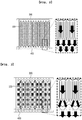
- FIG. 2 is a view illustrating a heat transfer part disposed in a battery module according to a comparative example
- FIG. 3 is a view illustrating a first heat transfer part in a battery module according to one embodiment of the present disclosure.
- an inner surface of the housing 200 in the battery module according to the comparative example has a planar shape.
- the first heat transfer part 400 may be formed in a shape as shown in FIG. 2 .
- the direction and area in which heat is transferred from the inside of the battery cell 100 toward the outside may not be efficient as compared to FIG.
- FIG. 3 is for illustrating the first heat transfer part 400 of the present disclosure, and it can be confirmed that the inner surface of the housing 200 has a shape curved along the curve of the battery cell 100, unlike FIG. 2 . Accordingly, it can be confirmed that the first heat transfer part 400 formed between one side of the battery cell 100 and the inner surface of the housing 200 is thinly disposed along the curve of the battery cell 100, unlike FIG. 2 .
- the first heat transfer part 400 is formed in a thin and curved shape in this way, a thermal resistance becomes low when the heat generated in the battery cell 100 is transferred to the outside of the housing 200 through the first heat transfer part 400. That is, as compared with the battery module shown in FIG. 2 , the heat transfer path from the battery cell 100 to the first heat transfer part 400 has been reduced compared to the previous one. Further, it can be confirmed that due to the first heat transfer part 400 having the same shape as the curve of the battery cell 100, an effect of expanding the heat transfer area can also be obtained.
- FIG. 4 is a view illustrating a first heat transfer part in a battery module according to another embodiment of the present disclosure.
- both the inner surface and outer surface of the housing 200 are curved along the curve of the battery cell 100.
- FIG. 3 there is an effect that the heat transfer path is reduced and the heat transfer area is increased in the process of heat transfer from the first heat transfer part 400 to the housing 200
- FIG. 4 there is an effect that the heat transfer path is reduced and the heat transfer area is increased in the transfer process from the first heat transfer part 400 to the housing 200 as well as in the process of transferring heat from the housing 200 to the outside of the housing 200, which is different from FIG. 3 . That is, as shown in FIG.
- the thermal resistance can be minimized in the process of heat transfer from the battery cell 100 toward the outside of the housing 200.
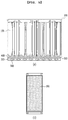
- FIG. 5 is a view illustrating a second heat transfer part in a battery module according to one embodiment of the present disclosure
- FIG. 6 is a view illustrating a second heat transfer part in a battery module according to another embodiment of the present disclosure.
- FIG. 5(a) is a view showing one embodiment in which only the inner surface of the housing 200 is curved as shown in FIG. 3 and the outer surface of the housing 200 is flat-shaped.
- the second heat transfer part 500 disposed between the outer surface of the housing 200 and the cooling part 300 may be formed in a shape of a flat plane as shown in FIG. 5(b) .
- FIG. 6(a) shows another embodiment in which both the inner surface and the outer surface of the housing 200 have a shape curved in accordance with the curved shape of one side of the battery cell 100. That is, it can be confirmed that in FIG. 6 , the second heat transfer part 500 is disposed along the curve formed on the outer surface of the housing 200 and is different from the shape of a flat plane shown in FIG. 5 .
- a groove 210 may be formed in parallel with the curve by the curve of the outer surface of the housing 200.
- the second heat transfer part 500 is formed inside the groove 210 formed by the curve as described above.
- the second heat transfer part 500 has a rod shape, and a plurality of second heat transfer parts 500 may be formed inside a plurality of grooves 210 formed by the curve, respectively. The plurality of second heat transfer parts 500 thus formed may be spaced apart from each other.
- the housing 200 may be formed to be curved in a shape having a certain thickness. In the case of the housing 200 in which both the inner surface and the outer surface have a curved shape in this way, an area cooled by the cooling part 300 disposed outside the housing 200 can be enlarged.
- a thermal resistance (K/W) in the process of heat transfer from the battery cell 100 to the cooling part 300 is lowered, thereby increasing the cooling efficiency through the cooling part 300.
- the thermal resistance (K/W) is proportional to a length (m) of the heat transfer path and inversely proportional to a thermal conductivity (W/m/K] and an area (m 2 ) of heat transfer. Accordingly, the present disclosure aims to reduce the length of the heat transfer path and increase the area of heat transfer as much as possible through the structures of FIGS. 4 and 6 , thereby finally minimizing the thermal resistance.
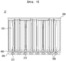
- FIG. 7 is a view illustrating a battery module according to another embodiment of the present disclosure.
- the second heat transfer part 500 of FIG. 7 is not a flat shape as in FIG. 5 , but may be a shape formed inside the groove 210 formed outside the housing 200 as in FIG. 6 .
- the shape of the second heat transfer part 500 formed inside the groove 210, and the shape of the cooling part 300 disposed on one side of the second heat transfer part 500 are different.
- the cooling part 300 shown in FIG. 7 is disposed on the outer surface of the housing 200 and may have a shape curved in accordance with the shape of the groove 210 on the outer surface of the housing 200.
- the cooling part 300 has a shape protruding convexly toward the groove 210 of the housing 200 at a position corresponding to the groove 210 formed on the outer surface of the housing 200
- the shape of the second heat transfer part 500 formed inside the groove 210 of the housing 200 may be different due to the arrangement of the cooling part 300.
- the second heat transfer part 500 is disposed in a space between the groove 210 having a recessed shape and the cooling part 300 having a convex shape protruding at a position corresponding thereto, and may be disposed to have a certain thickness along the space therebetween.
- FIG. 7 has the effects of minimizing the second heat transfer part 500, and of increasing the area where the second heat transfer part 500 and the cooling part 300 come into contact with each other, thereby improving the cooling efficiency due to an increase in the cooling area.
- the first heat transfer part 400 in the present disclosure is made of a material capable of fixing the battery cell 100 and conducting heat, and may be made of a conductive adhesive; and the second heat transfer part 500 may be made of a heat dissipating grease, a conductive adhesive or a heat dissipating pad, but is not limited thereto.
- a battery pack may include a battery module 10, wherein the battery module 10 includes: a plurality of battery cells 100, a housing 200 accommodating the plurality of battery cells 100, and a cooling part 300 disposed on an outer surface of the housing 200, wherein the battery module includes a first heat transfer part 400 formed on an inner surface of the housing 200 so as to make contact with one side of the plurality of battery cells 100, and wherein the housing 200 may have a curved portion in accordance with a curved shape of the plurality of battery cells 100.
- the technical significance of the present disclosure resides in that in the process of heat transfer between an inside of the secondary battery and a cooling part disposed outside the secondary battery, the thermal resistance is lowered by increasing a heat transfer area of the contacted portion and reducing a heat transfer path, thereby improving a cooling performance of a battery module and thus, efficiently dissipate heat inside the secondary battery.
- the battery module described above may be included in the battery pack.
- the battery pack may have a structure in which one or more battery modules according to the present embodiment are collected, and then packed by adding a battery management system (BMS) and a cooling device to manage the temperature or voltage of the battery.
- BMS battery management system
- the battery pack can be applied to various devices.
- a device may be applied to vehicles such as an electric bicycle, an electric vehicle, or a hybrid vehicle, but the present disclosure is not limited thereto, and can be applied to various devices capable of using a battery module, which also belongs to the scope of the present disclosure.
Landscapes
- Chemical & Material Sciences (AREA)
- Chemical Kinetics & Catalysis (AREA)
- Electrochemistry (AREA)
- General Chemical & Material Sciences (AREA)
- Engineering & Computer Science (AREA)
- Manufacturing & Machinery (AREA)
- Secondary Cells (AREA)
- Battery Mounting, Suspending (AREA)
Abstract
Description
- This application claims the benefit of Korean Patent Application No.
10-2019-0001978 filed on January 7, 2019 - The present disclosure relates to a battery module and a battery pack including the same, and more particularly, to a battery module having improved cooling performance, and a battery pack including the same.
- In modern society, as portable devices such as a mobile phone, a notebook computer, a camcorder and a digital camera has been daily used, the development of technologies in the fields related to mobile devices as described above has been activated. In addition, rechargeable secondary batteries are used as a power source for an electric vehicle (EV), a hybrid electric vehicle (HEV), a plug-in hybrid electric vehicle (P-HEV) and the like, in an attempt to solve air pollution and the like caused by existing gasoline vehicles using fossil fuel, and therefore, there is an increasing need for development of the secondary battery.
- In the case of a secondary battery used in small appliances, two to three battery cells are disposed therein, but in the case of a secondary battery used in a medium- or large-sized device such as an automobile, a battery module having a plurality of battery cells electrically connected with each other is used.
- In the case of the battery module used in such a medium- or large-sized device, in order to provide a capacity above a specific value required by the device, a plurality of battery cells are electrically connected in series with each other and used. In this case, the stability of the secondary battery itself varies depending on a method of connecting the plurality of battery cells, a method of fixing them, and the like.
- In particular, in the secondary battery having increased capacity as described above, the way of cooling the battery in order to prevent a problem caused by overheating of the battery is important. It is necessary to efficiently dissipate heat inside the battery, and as a method for dissipating heat in the secondary battery, there is mentioned a method of applying a thermal interface material (TIM) on a surface coupled with the secondary battery.
- The thermal interface material (TIM), also referred to as a thermal surface material, means that in a path through which heat is transferred, said material is filled between the respective surfaces to adjust a contact area of the surface through which heat is transferred and finally adjust the path of heat transfer, thereby adjusting the thermal resistance.
- In order to prevent a problem caused by overheating in the secondary battery as described above, it is necessary to develop a technique for efficiently dissipating heat inside the battery to the outside of the battery.
- Embodiments of the present disclosure are designed to solve the problems as described above, and therefore, an object of the present disclosure is to provide a battery module which improves the cooling efficiency of a secondary battery by adjusting a contacted portion in the heat transfer path in the process of transferring heat generated inside the secondary battery to a cooling part disposed outside the battery to minimize the thermal resistance, and a battery pack including the same.
- However, the problem to be solved by the embodiments of the present disclosure is not limited to the above-described problems, and can be variously expanded within the scope of the technical idea included in the present disclosure.
- According to a feature of the present disclosure for achieving the above object, there is provided a battery module comprising: a plurality of battery cells, a housing accommodating the plurality of battery cells, and a cooling part disposed on an outer surface of the housing, wherein the battery module includes a first heat transfer part formed on an inner surface of the housing so as to make contact with one side of the plurality of battery cells, and wherein the housing may have a curved portion in accordance with a curved shape of the plurality of battery cells.
- At least one of the inner surface and the outer surface of the housing may have a curved portion.
- The first heat transfer part formed to make contact with the curved portion of the housing may have a curved portion formed along the curve of the housing.
- The battery module further includes a second heat transfer part disposed between the outer surface of the housing and the cooling part so as to make contact with the outer surface of the housing.
- The second heat transfer part may have a planar shape.
- By the curve of the outer surface of the housing, the second heat transfer part may be formed inside a groove formed by the curve.
- The second heat transfer part may have a rod shape.
- The second heat transfer part is composed of a plurality of parts, and the plurality of second heat transfer parts may be spaced apart from each other while being inserted into a plurality of grooves formed by the curve, respectively.
- The housing between the first heat transfer part and the second heat transfer part may be formed such that both the inner surface and the outer surface are curved.
- The first heat transfer part may have a curved shape.
- The first heat transfer part may be a conductive adhesive.
- The second heat transfer part may be one of a heat dissipating grease, a conductive adhesive, and a heat dissipating pad.
- In addition, according to another feature of the present disclosure for achieving the above object, there is provided a battery pack comprising a battery module, wherein the battery module comprises: a plurality of battery cells, a housing accommodating the plurality of battery cells, and a cooling part disposed on an outer surface of the housing, wherein the battery module includes a first heat transfer part formed on an inner surface of the housing so as to make contact with one side of the plurality of battery cells, and wherein the housing may have a curved portion in accordance with a curved shape of the plurality of battery cells.
- The battery module according to embodiments of the present disclosure can increase the cooling performance by using a curved shape, and efficiently dissipate the heat inside the secondary battery
-
-
FIG. 1 is a view showing a cross section of a battery module according to one embodiment of the present disclosure. -
FIG. 2 is a view illustrating a heat transfer part disposed in a battery module according to a comparative example. -
FIG. 3 is a view illustrating a first heat transfer part in a battery module according to one embodiment of the present disclosure. -
FIG. 4 is a view illustrating a first heat transfer part in a battery module according to another embodiment of the present disclosure. -
FIG. 5 is a view illustrating a second heat transfer part in a battery module according to one embodiment of the present disclosure. -
FIG. 6 is a view illustrating a second heat transfer part in a battery module according to another embodiment of the present disclosure. -
FIG. 7 is a view illustrating a battery module according to another embodiment of the present disclosure. - Hereinafter, various embodiments of the present disclosure will be described in detail with reference to the accompanying drawings so that those skilled in the art can easily implement them. The present disclosure may be modified in various different ways, and is not limited to the embodiments set forth herein.
- Parts that are irrelevant to the description will be omitted to clearly describe the present disclosure, and like reference numerals designate like elements throughout the specification.
- Further, in the drawings, the size and thickness of each element are arbitrarily illustrated for convenience of description, and the present disclosure is not necessarily limited to those illustrated in the drawings. In the drawings, the thickness of layers, regions, etc. are exaggerated for clarity. In the drawings, for convenience of description, the thicknesses of some layers and regions are exaggerated.
- Further, throughout the specification, when a part is referred to as "including" a certain component, it means that it can further include other components, without excluding the other components, unless otherwise stated.
-
FIG. 1 is a view showing a cross section of a battery module according to one embodiment of the present disclosure. - As shown in
FIG. 1 , abattery module 10 according to one embodiment of the present disclosure includes a plurality ofbattery cells 100, ahousing 200 accommodating the plurality ofbattery cells 100, and acooling part 300 disposed on an outer surface of thehousing 200 and having arefrigerant 310 flowing therein, wherein thebattery module 10 includes a firstheat transfer part 400 formed on an inner surface of thehousing 200 so as to make contact with one side of the plurality ofbattery cells 100, and thehousing 200 may have a curved portion in accordance with a curved shape of the plurality ofbattery cells 100. In addition, the battery module of the present disclosure may further include a secondheat transfer part 500 which is disposed between the outer surface of thehousing 200 and thecooling part 300 so as to make contact with the outer surface of thehousing 200. - In
FIG. 1 , both the inner surface and the outer surface of thehousing 200 have a curved shape, but are not limited thereto. At least one of the inner surface and the outer surface of thehousing 200 in the present disclosure may have a curved portion along the curve of the plurality ofbattery cells 100, whereby at least one of the firstheat transfer part 400 and the secondheat transfer part 500 disposed to make contact with the curved portion of thehousing 200 may be formed along the curve of thehousing 200. - This will be described below in detail with reference to
FIGS. 2 to 6 . -
FIG. 2 is a view illustrating a heat transfer part disposed in a battery module according to a comparative example, andFIG. 3 is a view illustrating a first heat transfer part in a battery module according to one embodiment of the present disclosure. - As shown in
FIG. 2 , it can be confirmed that an inner surface of thehousing 200 in the battery module according to the comparative example has a planar shape. In this case, between the lower surface of the plurality ofbattery cells 100 and the inner surface of theflat housing 200, the firstheat transfer part 400 may be formed in a shape as shown inFIG. 2 . As can be seen in the enlarged drawing, when looking at the process and direction of transferring the heat generated in thebattery cell 100, the direction and area in which heat is transferred from the inside of thebattery cell 100 toward the outside may not be efficient as compared toFIG. 3 showing the battery module according to one embodiment of the present disclosure described below, depending on the shape of thecurved battery cell 100, the shape of the firstheat transfer part 400 in contact with thebattery cell 100, and the shape of the portion where the first heat transferpart 400 and thehousing 200 come into contact. -
FIG. 3 is for illustrating the firstheat transfer part 400 of the present disclosure, and it can be confirmed that the inner surface of thehousing 200 has a shape curved along the curve of thebattery cell 100, unlikeFIG. 2 . Accordingly, it can be confirmed that the firstheat transfer part 400 formed between one side of thebattery cell 100 and the inner surface of thehousing 200 is thinly disposed along the curve of thebattery cell 100, unlikeFIG. 2 . - As the first
heat transfer part 400 is formed in a thin and curved shape in this way, a thermal resistance becomes low when the heat generated in thebattery cell 100 is transferred to the outside of thehousing 200 through the firstheat transfer part 400. That is, as compared with the battery module shown inFIG. 2 , the heat transfer path from thebattery cell 100 to the firstheat transfer part 400 has been reduced compared to the previous one. Further, it can be confirmed that due to the firstheat transfer part 400 having the same shape as the curve of thebattery cell 100, an effect of expanding the heat transfer area can also be obtained. -
FIG. 4 is a view illustrating a first heat transfer part in a battery module according to another embodiment of the present disclosure. - Referring to
FIG. 4 , unlike the battery module ofFIG. 3 in which only the inner surface of thehousing 200 was curved, it can be confirmed that inFIG. 4 , both the inner surface and outer surface of thehousing 200 are curved along the curve of thebattery cell 100. - In
FIG. 3 , there is an effect that the heat transfer path is reduced and the heat transfer area is increased in the process of heat transfer from the firstheat transfer part 400 to thehousing 200, whereas inFIG. 4 , there is an effect that the heat transfer path is reduced and the heat transfer area is increased in the transfer process from the firstheat transfer part 400 to thehousing 200 as well as in the process of transferring heat from thehousing 200 to the outside of thehousing 200, which is different fromFIG. 3 . That is, as shown inFIG. 4 , when the inner surface and the outer surface of thehousing 200, and the firstheat transfer part 400 disposed between one side of thebattery cell 100 and thehousing 200 are all curved like thebattery cell 100, the thermal resistance can be minimized in the process of heat transfer from thebattery cell 100 toward the outside of thehousing 200. -
FIG. 5 is a view illustrating a second heat transfer part in a battery module according to one embodiment of the present disclosure, andFIG. 6 is a view illustrating a second heat transfer part in a battery module according to another embodiment of the present disclosure. -
FIG. 5(a) is a view showing one embodiment in which only the inner surface of thehousing 200 is curved as shown inFIG. 3 and the outer surface of thehousing 200 is flat-shaped. In this case, the secondheat transfer part 500 disposed between the outer surface of thehousing 200 and thecooling part 300 may be formed in a shape of a flat plane as shown inFIG. 5(b) . - Meanwhile,
FIG. 6(a) shows another embodiment in which both the inner surface and the outer surface of thehousing 200 have a shape curved in accordance with the curved shape of one side of thebattery cell 100. That is, it can be confirmed that inFIG. 6 , the secondheat transfer part 500 is disposed along the curve formed on the outer surface of thehousing 200 and is different from the shape of a flat plane shown inFIG. 5 . - In the
housing 200 inFIG. 6 , agroove 210 may be formed in parallel with the curve by the curve of the outer surface of thehousing 200. As shown inFIG. 6(a) , the secondheat transfer part 500 is formed inside thegroove 210 formed by the curve as described above. As inFIG. 6(b) showing a state in which the secondheat transfer part 500 is disposed, the secondheat transfer part 500 has a rod shape, and a plurality of secondheat transfer parts 500 may be formed inside a plurality ofgrooves 210 formed by the curve, respectively. The plurality of secondheat transfer parts 500 thus formed may be spaced apart from each other. - As shown in
FIG. 6(a) , between the firstheat transfer part 400 and the secondheat transfer part 500, thehousing 200 may be formed to be curved in a shape having a certain thickness. In the case of thehousing 200 in which both the inner surface and the outer surface have a curved shape in this way, an area cooled by the coolingpart 300 disposed outside thehousing 200 can be enlarged. - That is, it can be said that through the structure as above, a thermal resistance (K/W) in the process of heat transfer from the
battery cell 100 to thecooling part 300 is lowered, thereby increasing the cooling efficiency through the coolingpart 300. The thermal resistance (K/W) is proportional to a length (m) of the heat transfer path and inversely proportional to a thermal conductivity (W/m/K] and an area (m2) of heat transfer. Accordingly, the present disclosure aims to reduce the length of the heat transfer path and increase the area of heat transfer as much as possible through the structures ofFIGS. 4 and6 , thereby finally minimizing the thermal resistance. -
FIG. 7 is a view illustrating a battery module according to another embodiment of the present disclosure. - As shown in
FIG. 7 , it can be confirmed that the secondheat transfer part 500 ofFIG. 7 is not a flat shape as inFIG. 5 , but may be a shape formed inside thegroove 210 formed outside thehousing 200 as inFIG. 6 . However, due to the difference between the embodiments illustrated inFIG. 7 andFIG. 6 , it can be confirmed that the shape of the secondheat transfer part 500 formed inside thegroove 210, and the shape of thecooling part 300 disposed on one side of the secondheat transfer part 500 are different. - First, the cooling
part 300 shown inFIG. 7 is disposed on the outer surface of thehousing 200 and may have a shape curved in accordance with the shape of thegroove 210 on the outer surface of thehousing 200. As such, when thecooling part 300 has a shape protruding convexly toward thegroove 210 of thehousing 200 at a position corresponding to thegroove 210 formed on the outer surface of thehousing 200, the shape of the secondheat transfer part 500 formed inside thegroove 210 of thehousing 200 may be different due to the arrangement of thecooling part 300. That is, the secondheat transfer part 500 is disposed in a space between thegroove 210 having a recessed shape and thecooling part 300 having a convex shape protruding at a position corresponding thereto, and may be disposed to have a certain thickness along the space therebetween. - That is, there is a difference in that the second
heat transfer part 500 inFIG. 6 has a shape disposed to fill thegroove 210, whereas the secondheat transfer part 500 inFIG. 7 has a shape disposed to fill only the space between thegroove 210 and thecooling part 300 disposed along the curve of thegroove 210. Due to this structural difference, as compared toFIG. 6 ,FIG. 7 has the effects of minimizing the secondheat transfer part 500, and of increasing the area where the secondheat transfer part 500 and thecooling part 300 come into contact with each other, thereby improving the cooling efficiency due to an increase in the cooling area. - The first
heat transfer part 400 in the present disclosure is made of a material capable of fixing thebattery cell 100 and conducting heat, and may be made of a conductive adhesive; and the secondheat transfer part 500 may be made of a heat dissipating grease, a conductive adhesive or a heat dissipating pad, but is not limited thereto. - In addition, a battery pack according to one embodiment of the present disclosure may include a
battery module 10, wherein thebattery module 10 includes: a plurality ofbattery cells 100, ahousing 200 accommodating the plurality ofbattery cells 100, and acooling part 300 disposed on an outer surface of thehousing 200, wherein the battery module includes a firstheat transfer part 400 formed on an inner surface of thehousing 200 so as to make contact with one side of the plurality ofbattery cells 100, and wherein thehousing 200 may have a curved portion in accordance with a curved shape of the plurality ofbattery cells 100. - As described above, the technical significance of the present disclosure resides in that in the process of heat transfer between an inside of the secondary battery and a cooling part disposed outside the secondary battery, the thermal resistance is lowered by increasing a heat transfer area of the contacted portion and reducing a heat transfer path, thereby improving a cooling performance of a battery module and thus, efficiently dissipate heat inside the secondary battery.
- The battery module described above may be included in the battery pack. The battery pack may have a structure in which one or more battery modules according to the present embodiment are collected, and then packed by adding a battery management system (BMS) and a cooling device to manage the temperature or voltage of the battery.
- The battery pack can be applied to various devices. Such a device may be applied to vehicles such as an electric bicycle, an electric vehicle, or a hybrid vehicle, but the present disclosure is not limited thereto, and can be applied to various devices capable of using a battery module, which also belongs to the scope of the present disclosure.
- Although the preferred embodiments of the present disclosure have been described in detail above, the scope of the present disclosure is not limited thereto, and various modifications and improvements of those skilled in the art using the basic concepts of the present disclosure defined in the following claims also belong to the scope of rights.
-
- 10:
- battery module
- 100:
- battery cell
- 200:
- housing
- 210:
- groove
- 300:
- cooling part
- 310:
- refrigerant
- 400:
- first heat transfer part
- 500:
- second heat transfer part
Claims (13)
- A battery module comprising: a plurality of battery cells, a housing accommodating the plurality of battery cells, and a cooling part disposed on an outer surface of the housing,
wherein the battery module includes a first heat transfer part formed on an inner surface of the housing so as to make contact with one side of the plurality of battery cells, and
wherein the housing has a curved portion in accordance with a curved shape of the plurality of battery cells. - The battery module of claim 1, wherein at least one of the inner surface and the outer surface of the housing has a curved portion.
- The battery module of claim 2, wherein the first heat transfer part formed to make contact with the curved portion of the housing has a curved portion formed along the curve of the housing.
- The battery module of claim 1, wherein the battery module further comprises a second heat transfer part disposed between the outer surface of the housing and the cooling part so as to make contact with the outer surface of the housing.
- The battery module of claim 4, wherein the second heat transfer part has a planar shape.
- The battery module of claim 4, wherein by the curve of the outer surface of the housing, the second heat transfer part is formed inside a groove formed by the curve.
- The battery module of claim 6, wherein the second heat transfer part has a rod shape.
- The battery module of claim 4, wherein the second heat transfer part is composed of a plurality of parts, and
the plurality of second heat transfer parts are spaced apart from each other while being inserted into a plurality of grooves formed by the curve, respectively. - The battery module of claim 4, wherein the housing between the first heat transfer part and the second heat transfer part is formed such that both the inner surface and the outer surface are curved.
- The battery module of claim 1, wherein the first heat transfer part has a curved shape.
- The battery module of claim 1, wherein the first heat transfer part is a conductive adhesive.
- The battery module of claim 1, wherein the second heat transfer part is one of a heat dissipating grease, a conductive adhesive and a heat dissipating pad.
- A battery pack comprising the battery module according to claim 1.
Applications Claiming Priority (2)
| Application Number | Priority Date | Filing Date | Title |
|---|---|---|---|
| KR1020190001978A KR102409856B1 (en) | 2019-01-07 | 2019-01-07 | Battery module, and battery pack including the same |
| PCT/KR2020/000207 WO2020145600A1 (en) | 2019-01-07 | 2020-01-06 | Battery module, and battery pack including same |
Publications (2)
| Publication Number | Publication Date |
|---|---|
| EP3780251A1 true EP3780251A1 (en) | 2021-02-17 |
| EP3780251A4 EP3780251A4 (en) | 2021-06-23 |
Family
ID=71520813
Family Applications (1)
| Application Number | Title | Priority Date | Filing Date |
|---|---|---|---|
| EP20737878.7A Pending EP3780251A4 (en) | 2019-01-07 | 2020-01-06 | BATTERY MODULE AND BATTERY PACK INCLUDING IT |
Country Status (6)
| Country | Link |
|---|---|
| US (1) | US11757148B2 (en) |
| EP (1) | EP3780251A4 (en) |
| JP (1) | JP7214292B2 (en) |
| KR (1) | KR102409856B1 (en) |
| CN (1) | CN112204806B (en) |
| WO (1) | WO2020145600A1 (en) |
Cited By (1)
| Publication number | Priority date | Publication date | Assignee | Title |
|---|---|---|---|---|
| EP4379908A4 (en) * | 2022-04-12 | 2025-04-30 | LG Energy Solution, Ltd. | BATTERY MODULE WITH INCREASED SAFETY |
Families Citing this family (9)
| Publication number | Priority date | Publication date | Assignee | Title |
|---|---|---|---|---|
| US20220384875A1 (en) * | 2020-08-24 | 2022-12-01 | Lg Energy Solution, Ltd. | Battery module and battery pack including the same |
| US11476517B2 (en) | 2020-09-21 | 2022-10-18 | Rivian Ip Holdings, Llc | Temperature gradient control with thermal interface material variation |
| KR20220078765A (en) | 2020-12-03 | 2022-06-13 | 주식회사 엘지에너지솔루션 | Battery pack and device including the same |
| KR20220082297A (en) * | 2020-12-10 | 2022-06-17 | 주식회사 엘지에너지솔루션 | Battery module and battery pack including the same |
| WO2023059110A1 (en) * | 2021-10-06 | 2023-04-13 | 주식회사 엘지에너지솔루션 | Battery module |
| JP7678215B2 (en) * | 2022-06-27 | 2025-05-15 | エルジー エナジー ソリューション リミテッド | Battery pack |
| JPWO2025089150A1 (en) * | 2023-10-24 | 2025-05-01 | ||
| CN118156627A (en) * | 2024-05-10 | 2024-06-07 | 晶科储能科技有限公司 | Secondary battery, battery pack and energy storage box |
| KR20250168811A (en) * | 2024-05-24 | 2025-12-02 | 주식회사 엘지에너지솔루션 | Battery device |
Family Cites Families (20)
| Publication number | Priority date | Publication date | Assignee | Title |
|---|---|---|---|---|
| JP5942765B2 (en) | 2012-10-15 | 2016-06-29 | トヨタ自動車株式会社 | Power storage module and heat transfer member |
| JP2014093240A (en) | 2012-11-06 | 2014-05-19 | Nissan Motor Co Ltd | Battery module |
| KR20140074151A (en) * | 2012-12-07 | 2014-06-17 | 타이코에이엠피(유) | Battery module |
| KR102028916B1 (en) * | 2012-12-31 | 2019-10-08 | 에스케이이노베이션 주식회사 | Battery Pack for Secondary Battery |
| JP2015056218A (en) | 2013-09-10 | 2015-03-23 | トヨタ自動車株式会社 | Temperature control structure of power storage device |
| CN112531255B (en) | 2015-02-27 | 2023-07-07 | 株式会社Lg新能源 | battery module |
| KR101778667B1 (en) | 2015-03-09 | 2017-09-26 | 주식회사 엘지화학 | Battery Module Comprising Cooling plates |
| KR101865995B1 (en) * | 2015-03-27 | 2018-06-08 | 주식회사 엘지화학 | Battery module |
| KR102006412B1 (en) | 2015-06-12 | 2019-08-02 | 주식회사 엘지화학 | Battery module |
| KR101900998B1 (en) * | 2015-06-18 | 2018-09-20 | 주식회사 엘지화학 | Lightweight cooling plate, battery module comprising the same and fabricating method thereof |
| KR101939832B1 (en) * | 2015-09-23 | 2019-01-17 | 주식회사 엘지화학 | Battery module and battery pack including the same and method for manufacturing a battery module casing |
| PL3361554T3 (en) * | 2015-12-14 | 2021-03-08 | Lg Chem, Ltd. | Battery module, battery pack comprising battery module, and vehicle comprising battery pack |
| EP3373358B1 (en) | 2015-12-18 | 2021-02-03 | LG Chem, Ltd. | Battery pack |
| KR102072765B1 (en) * | 2016-02-22 | 2020-03-02 | 주식회사 엘지화학 | Battery module, battery pack comprising the battery module and vehicle comprising the battery pack |
| KR102172515B1 (en) * | 2016-03-16 | 2020-10-30 | 주식회사 엘지화학 | Battery module |
| KR102256606B1 (en) | 2016-05-31 | 2021-05-26 | 주식회사 엘지에너지솔루션 | Battery module, battery pack comprising the battery module and vehicle comprising the battery pack |
| KR102051108B1 (en) | 2016-06-13 | 2019-12-02 | 주식회사 엘지화학 | Battery module, battery pack comprising the battery module and vehicle comprising the battery pack |
| KR102120118B1 (en) * | 2016-08-18 | 2020-06-08 | 주식회사 엘지화학 | Battery module |
| KR102086127B1 (en) * | 2016-10-31 | 2020-03-06 | 주식회사 엘지화학 | Battery pack for providing direct cooling means to edge side of battery |
| US12136719B2 (en) | 2019-08-03 | 2024-11-05 | Sanyo Electric Co., Ltd. | Power supply device, electric vehicle comprising said power supply device, and power storage device |
-
2019
- 2019-01-07 KR KR1020190001978A patent/KR102409856B1/en active Active
-
2020
- 2020-01-06 JP JP2020564484A patent/JP7214292B2/en active Active
- 2020-01-06 CN CN202080002949.9A patent/CN112204806B/en active Active
- 2020-01-06 US US17/057,883 patent/US11757148B2/en active Active
- 2020-01-06 EP EP20737878.7A patent/EP3780251A4/en active Pending
- 2020-01-06 WO PCT/KR2020/000207 patent/WO2020145600A1/en not_active Ceased
Cited By (1)
| Publication number | Priority date | Publication date | Assignee | Title |
|---|---|---|---|---|
| EP4379908A4 (en) * | 2022-04-12 | 2025-04-30 | LG Energy Solution, Ltd. | BATTERY MODULE WITH INCREASED SAFETY |
Also Published As
| Publication number | Publication date |
|---|---|
| US20210203020A1 (en) | 2021-07-01 |
| EP3780251A4 (en) | 2021-06-23 |
| JP7214292B2 (en) | 2023-01-30 |
| CN112204806B (en) | 2024-12-20 |
| KR20200085616A (en) | 2020-07-15 |
| CN112204806A (en) | 2021-01-08 |
| KR102409856B1 (en) | 2022-06-15 |
| WO2020145600A1 (en) | 2020-07-16 |
| JP2021524137A (en) | 2021-09-09 |
| US11757148B2 (en) | 2023-09-12 |
Similar Documents
| Publication | Publication Date | Title |
|---|---|---|
| US11757148B2 (en) | Battery module, and battery pack including the same | |
| KR102523702B1 (en) | Battery module | |
| CN104604018B (en) | battery module assembly | |
| US12548822B2 (en) | Battery pack and device including the same | |
| WO2015126204A1 (en) | Battery pack for automobile having improved cooling efficiency | |
| CN102422459A (en) | Battery case including elastic pressing member and battery module including same | |
| EP3934009B1 (en) | Battery module and battery pack including same | |
| US12046731B2 (en) | Battery module, method for preparing the same and battery pack including the same | |
| CN216958206U (en) | Battery module and battery pack including the same | |
| EP4040575A1 (en) | Battery module and battery pack including same | |
| EP3907811A1 (en) | Battery module and battery pack comprising same | |
| US20250030082A1 (en) | Battery Module, Method for Preparing the Same and Battery Pack Including the Same | |
| EP4047719A1 (en) | Battery module and method for manufacturing same | |
| US12021212B2 (en) | Battery module, and battery pack and vehicle comprising same | |
| EP4191751A1 (en) | Battery blocking unit and battery pack including same | |
| EP4181274A1 (en) | Battery module and battery pack including same | |
| WO2023050923A1 (en) | Battery cell, battery, and electric device | |
| KR20230084757A (en) | Cooling fin, battery module and battery pack including the same | |
| CN115428233A (en) | Battery module and battery pack including the same | |
| CN116250116B (en) | Battery pack and apparatus including the battery pack | |
| CN120600969A (en) | Battery pack | |
| CN119605020A (en) | Heat transfer in battery module assemblies | |
| KR20230008531A (en) | Battery module, battery pack including the same and manufacturing method of secondary battery |
Legal Events
| Date | Code | Title | Description |
|---|---|---|---|
| STAA | Information on the status of an ep patent application or granted ep patent |
Free format text: STATUS: THE INTERNATIONAL PUBLICATION HAS BEEN MADE |
|
| PUAI | Public reference made under article 153(3) epc to a published international application that has entered the european phase |
Free format text: ORIGINAL CODE: 0009012 |
|
| STAA | Information on the status of an ep patent application or granted ep patent |
Free format text: STATUS: REQUEST FOR EXAMINATION WAS MADE |
|
| 17P | Request for examination filed |
Effective date: 20201105 |
|
| AK | Designated contracting states |
Kind code of ref document: A1 Designated state(s): AL AT BE BG CH CY CZ DE DK EE ES FI FR GB GR HR HU IE IS IT LI LT LU LV MC MK MT NL NO PL PT RO RS SE SI SK SM TR |
|
| AX | Request for extension of the european patent |
Extension state: BA ME |
|
| REG | Reference to a national code |
Ref country code: DE Ref legal event code: R079 Free format text: PREVIOUS MAIN CLASS: H01M0010655000 Ipc: H01M0010655400 |
|
| A4 | Supplementary search report drawn up and despatched |
Effective date: 20210521 |
|
| RIC1 | Information provided on ipc code assigned before grant |
Ipc: H01M 10/6554 20140101AFI20210517BHEP Ipc: H01M 10/6556 20140101ALI20210517BHEP Ipc: H01M 10/653 20140101ALI20210517BHEP Ipc: H01M 10/613 20140101ALI20210517BHEP Ipc: H01M 10/64 20140101ALI20210517BHEP Ipc: H01M 50/20 20210101ALI20210517BHEP |
|
| RAP1 | Party data changed (applicant data changed or rights of an application transferred) |
Owner name: LG ENERGY SOLUTION LTD. |
|
| RAP3 | Party data changed (applicant data changed or rights of an application transferred) |
Owner name: LG ENERGY SOLUTION, LTD. |
|
| DAV | Request for validation of the european patent (deleted) | ||
| DAX | Request for extension of the european patent (deleted) | ||
| STAA | Information on the status of an ep patent application or granted ep patent |
Free format text: STATUS: EXAMINATION IS IN PROGRESS |
|
| 17Q | First examination report despatched |
Effective date: 20230515 |
|
| GRAP | Despatch of communication of intention to grant a patent |
Free format text: ORIGINAL CODE: EPIDOSNIGR1 |
|
| STAA | Information on the status of an ep patent application or granted ep patent |
Free format text: STATUS: GRANT OF PATENT IS INTENDED |
|
| RIC1 | Information provided on ipc code assigned before grant |
Ipc: H01M 10/6554 20140101AFI20260402BHEP Ipc: H01M 10/6556 20140101ALI20260402BHEP Ipc: H01M 10/653 20140101ALI20260402BHEP Ipc: H01M 10/613 20140101ALI20260402BHEP Ipc: H01M 10/64 20140101ALI20260402BHEP Ipc: H01M 50/204 20210101ALI20260402BHEP |
|
| INTG | Intention to grant announced |
Effective date: 20260429 |
|
| P01 | Opt-out of the competence of the unified patent court (upc) registered |
Free format text: CASE NUMBER: UPC_APP_0014624_3780251/2026 Effective date: 20260504 |
|
| GRAS | Grant fee paid |
Free format text: ORIGINAL CODE: EPIDOSNIGR3 |
|
| GRAA | (expected) grant |
Free format text: ORIGINAL CODE: 0009210 |
|
| STAA | Information on the status of an ep patent application or granted ep patent |
Free format text: STATUS: THE PATENT HAS BEEN GRANTED |