EP3780156A1 - Lithium ion secondary battery and manufacturing method of the same - Google Patents
Lithium ion secondary battery and manufacturing method of the same Download PDFInfo
- Publication number
- EP3780156A1 EP3780156A1 EP20152168.9A EP20152168A EP3780156A1 EP 3780156 A1 EP3780156 A1 EP 3780156A1 EP 20152168 A EP20152168 A EP 20152168A EP 3780156 A1 EP3780156 A1 EP 3780156A1
- Authority
- EP
- European Patent Office
- Prior art keywords
- cathode
- leads
- anode
- welded
- bent
- Prior art date
- Legal status (The legal status is an assumption and is not a legal conclusion. Google has not performed a legal analysis and makes no representation as to the accuracy of the status listed.)
- Withdrawn
Links
Images



Classifications
-
- H—ELECTRICITY
- H01—ELECTRIC ELEMENTS
- H01M—PROCESSES OR MEANS, e.g. BATTERIES, FOR THE DIRECT CONVERSION OF CHEMICAL ENERGY INTO ELECTRICAL ENERGY
- H01M10/00—Secondary cells; Manufacture thereof
- H01M10/05—Accumulators with non-aqueous electrolyte
- H01M10/058—Construction or manufacture
-
- H—ELECTRICITY
- H01—ELECTRIC ELEMENTS
- H01M—PROCESSES OR MEANS, e.g. BATTERIES, FOR THE DIRECT CONVERSION OF CHEMICAL ENERGY INTO ELECTRICAL ENERGY
- H01M50/00—Constructional details or processes of manufacture of the non-active parts of electrochemical cells other than fuel cells, e.g. hybrid cells
- H01M50/50—Current conducting connections for cells or batteries
- H01M50/531—Electrode connections inside a battery casing
- H01M50/54—Connection of several leads or tabs of plate-like electrode stacks, e.g. electrode pole straps or bridges
-
- H—ELECTRICITY
- H01—ELECTRIC ELEMENTS
- H01M—PROCESSES OR MEANS, e.g. BATTERIES, FOR THE DIRECT CONVERSION OF CHEMICAL ENERGY INTO ELECTRICAL ENERGY
- H01M10/00—Secondary cells; Manufacture thereof
- H01M10/05—Accumulators with non-aqueous electrolyte
- H01M10/052—Li-accumulators
- H01M10/0525—Rocking-chair batteries, i.e. batteries with lithium insertion or intercalation in both electrodes; Lithium-ion batteries
-
- H—ELECTRICITY
- H01—ELECTRIC ELEMENTS
- H01M—PROCESSES OR MEANS, e.g. BATTERIES, FOR THE DIRECT CONVERSION OF CHEMICAL ENERGY INTO ELECTRICAL ENERGY
- H01M10/00—Secondary cells; Manufacture thereof
- H01M10/05—Accumulators with non-aqueous electrolyte
- H01M10/058—Construction or manufacture
- H01M10/0585—Construction or manufacture of accumulators having only flat construction elements, i.e. flat positive electrodes, flat negative electrodes and flat separators
-
- H—ELECTRICITY
- H01—ELECTRIC ELEMENTS
- H01M—PROCESSES OR MEANS, e.g. BATTERIES, FOR THE DIRECT CONVERSION OF CHEMICAL ENERGY INTO ELECTRICAL ENERGY
- H01M50/00—Constructional details or processes of manufacture of the non-active parts of electrochemical cells other than fuel cells, e.g. hybrid cells
- H01M50/50—Current conducting connections for cells or batteries
- H01M50/543—Terminals
-
- H—ELECTRICITY
- H01—ELECTRIC ELEMENTS
- H01M—PROCESSES OR MEANS, e.g. BATTERIES, FOR THE DIRECT CONVERSION OF CHEMICAL ENERGY INTO ELECTRICAL ENERGY
- H01M50/00—Constructional details or processes of manufacture of the non-active parts of electrochemical cells other than fuel cells, e.g. hybrid cells
- H01M50/50—Current conducting connections for cells or batteries
- H01M50/572—Means for preventing undesired use or discharge
- H01M50/574—Devices or arrangements for the interruption of current
-
- Y—GENERAL TAGGING OF NEW TECHNOLOGICAL DEVELOPMENTS; GENERAL TAGGING OF CROSS-SECTIONAL TECHNOLOGIES SPANNING OVER SEVERAL SECTIONS OF THE IPC; TECHNICAL SUBJECTS COVERED BY FORMER USPC CROSS-REFERENCE ART COLLECTIONS [XRACs] AND DIGESTS
- Y02—TECHNOLOGIES OR APPLICATIONS FOR MITIGATION OR ADAPTATION AGAINST CLIMATE CHANGE
- Y02E—REDUCTION OF GREENHOUSE GAS [GHG] EMISSIONS, RELATED TO ENERGY GENERATION, TRANSMISSION OR DISTRIBUTION
- Y02E60/00—Enabling technologies; Technologies with a potential or indirect contribution to GHG emissions mitigation
- Y02E60/10—Energy storage using batteries
-
- Y—GENERAL TAGGING OF NEW TECHNOLOGICAL DEVELOPMENTS; GENERAL TAGGING OF CROSS-SECTIONAL TECHNOLOGIES SPANNING OVER SEVERAL SECTIONS OF THE IPC; TECHNICAL SUBJECTS COVERED BY FORMER USPC CROSS-REFERENCE ART COLLECTIONS [XRACs] AND DIGESTS
- Y02—TECHNOLOGIES OR APPLICATIONS FOR MITIGATION OR ADAPTATION AGAINST CLIMATE CHANGE
- Y02P—CLIMATE CHANGE MITIGATION TECHNOLOGIES IN THE PRODUCTION OR PROCESSING OF GOODS
- Y02P70/00—Climate change mitigation technologies in the production process for final industrial or consumer products
- Y02P70/50—Manufacturing or production processes characterised by the final manufactured product
Definitions
- the present disclosure relates to a lithium ion secondary battery and a manufacturing method of the same, and more particularly, to a lithium ion secondary battery capable of increasing energy density and improving stability of a cell by forming non-welded portions having a predetermined length on a cathode lead and an anode lead.
- FIG. 1 is a view illustrating that interference between a cathode lead portion and an anode occurs when an electrode swells after a conventional lithium ion secondary battery is charged.
- the anode may be damaged due to the interference between the cathode lead portion and the anode when the electrode swells after the conventional lithium ion secondary battery is charged, and there was also a problem in that a short circuit between the cathode lead portion and the anode may occur to cause ignition.
- An object of the present disclosure is to provide a lithium ion secondary battery capable of increasing energy density and simultaneously improving stability of a cell by non-welded portions serving as a buffer when an electrode swells after charging, by forming the non-welded portions having a predetermined length on a cathode lead and an anode lead, and a manufacturing method of the same.
- a lithium ion secondary battery includes: a plurality of cathodes each including a cathode current collector, a cathode coating layer coating the cathode current collector, and a cathode lead; a plurality of anodes each including an anode current collector, an anode coating layer coating the anode current collector, and an anode lead; and a plurality of separation membranes arranged between the plurality of cathodes and the plurality of anodes, respectively.
- a plurality of cathode leads among the plurality of cathodes include first bent portions, respectively, at first points spaced apart from respective cathode coating layers by a predetermined distance.
- the plurality of cathode leads further include second bent portions, respectively, at second points where the plurality of cathode leads meet.
- the lithium ion secondary battery further includes a first overlapping portion at which the plurality of cathode leads overlap in parallel.
- the first overlapping portion includes a first welded portion to which the plurality of cathode leads are welded and a first non-welded portion to which the plurality of cathode leads are not welded.
- the first welded portion is welded to end portions of the plurality of cathode leads overlapping in parallel and a remaining portion of the first overlapping portion is not welded to the end portions of the plurality of cathode leads.
- the lithium ion secondary battery may further include a cathode tab disposed on a first end portion of the lithium ion secondary battery, wherein the first welded portion and the cathode tab are welded to each other at a cathode tab welded portion disposed therebetween, and wherein the second bent portions are spaced apart from an end of the cathode tab welded portion by a predetermined distance.
- the first non-welded portion is arranged between the first welded portion and the second bent portions, and a length of the first non-welded portion may be 2 mm or more.
- the first bent portions are spaced apart from an outermost one of the plurality of cathodes, the plurality of separation membranes, and the plurality of anodes.
- a plurality of anode leads among the plurality of anodes include third bent portions, respectively, at third points spaced apart from respective anode coating layers by a predetermined distance.
- the plurality of anode leads further include fourth bent portions, respectively, at fourth points where the plurality of anode leads meet.
- the lithium ion secondary battery further includes a second overlapping portion where the plurality of anode leads at the fourth points overlap in parallel.
- the second overlapping portion includes a second welded portion to which the plurality of anode leads are welded and a second non-welded portion to which the plurality of anode leads are not welded.
- the second welded portion is welded to end portions of the plurality of anode leads overlapping in parallel and a remaining portion of the second overlapping portion is not welded to the end portions of the plurality of anode leads.
- the lithium ion secondary battery may further include an anode tab disposed on a second end portion of the lithium ion secondary battery, wherein the second welded portion and the anode tab are welded to each other at an anode tab welded portion disposed therebetween, and wherein the fourth bent portions are spaced apart from an end of the anode tab welded portion by a predetermined distance.
- the second non-welded portion is arranged between the second welded portion and the fourth bent portions, and a length of the second non-welded portion may be 2 mm or more.
- the third bent portions are spaced apart from an outermost one of the plurality of anodes, the plurality of separation membranes, and the plurality of cathodes.
- a manufacturing method of a lithium ion secondary battery includes steps of: stacking a plurality of anodes, a plurality of separation membranes, and a plurality of cathodes; forming a first overlapping portion by pressing and bending a plurality of cathode leads at first points spaced apart from respective cathode coating layers by a first predetermined distance and by overlapping and fixing the plurality of cathode leads in parallel at second points where the plurality of bent cathode leads meet; and welding a portion of the first overlapping portion to end portions of the plurality of cathode leads.
- the step of forming a first overlapping portion includes steps of: simultaneously pressing and bending the plurality of cathode leads stacked in parallel from the top and bottom using a pair of lead fixing jigs at the first points spaced apart from the respective cathode coating layers by the first predetermined distance; and overlapping and fixing the plurality of cathode leads in parallel by pressing the plurality of bent cathode leads using the pair of lead fixing jigs until the plurality of cathode leads meet.
- the step of forming a first overlapping portion includes steps of: simultaneously pressing and bending the plurality of cathode leads stacked in parallel from the top and bottom using a pair of lead fixing jigs including an air nozzle at the first points spaced apart from the respective cathode coating layers by the first predetermined distance; and overlapping and fixing the plurality of cathode leads in parallel by pressing the plurality of bent cathode leads using the pair of lead fixing jigs until the plurality of cathode leads meet.
- the step of forming a first overlapping portion includes steps of: simultaneously pressing and bending the plurality of cathode leads stacked in parallel from the top and bottom using a pair of lead fixing jigs including a plurality of air nozzles at the first points spaced apart from the respective cathode coating layers by the first predetermined distance; and overlapping and fixing the plurality of cathode leads in parallel by pressing the plurality of bent cathode leads using the pair of lead fixing jigs until the plurality of cathode leads meet.
- the step of simultaneously pressing and bending the plurality of cathode leads stacked in parallel from the top and bottom using a pair of lead fixing jigs including a plurality of air nozzles includes steps of: raising and lowering the pair of lead fixing jigs by a predetermined distance as air is ejected obliquely to an outermost side of the plurality of air nozzles from an air nozzle located at the outermost side of the plurality of air nozzles; and ejecting air from an air nozzle located at an innermost side of the plurality of air nozzles after raising and lowering the pair of lead fixing jigs by the predetermined distance.
- the manufacturing method of a lithium ion secondary battery may further include a step of: before the step of simultaneously pressing and bending the plurality of cathode leads stacked in parallel from the top and bottom using a pair of lead fixing jigs including a plurality of air nozzles, inserting support pins in a direction perpendicular to the plurality of cathode leads in a direction in which the plurality of cathode leads are bent at points spaced apart from the respective cathode coating layers by a predetermined distance.
- the manufacturing method of a lithium ion secondary battery may further include steps of: forming a second overlapping portion by pressing and bending a plurality of anode leads at points spaced apart from respective anode coating layers by the first predetermined distance and overlapping and fixing the plurality of anode leads in parallel at a point where the plurality of bent anode leads meet; and welding a portion of the second overlapping portion to end portions of the plurality of anode leads.
- the step of forming a second overlapping portion includes steps of: simultaneously pressing and bending the plurality of anode leads stacked in parallel from the top and bottom using a pair of lead fixing jigs including an air nozzle at points spaced apart from the respective anode coating layers by the first predetermined distance; and overlapping and fixing the plurality of anode leads in parallel by pressing the plurality of bent cathode leads using the pair of lead fixing jigs until the plurality of bent cathode leads meet.
- the step of forming a second overlapping portion includes steps of: simultaneously pressing and bending the plurality of anode leads stacked in parallel from the top and bottom using a pair of lead fixing jigs including a plurality of air nozzles at points spaced apart from the respective anode coating layers by the first predetermined distance; and overlapping and fixing the plurality of anode leads in parallel by pressing the plurality of bent cathode leads using the pair of lead fixing jigs until the plurality of bent cathode leads meet.
- the step of simultaneously pressing and bending the plurality of anode leads stacked in parallel from the top and bottom using a pair of lead fixing jigs including a plurality of air nozzles includes: raising and lowering the pair of lead fixing jigs by a predetermined distance as air is ejected obliquely to an outermost side of the plurality of air nozzles from an air nozzle located at the outermost side of the plurality of air nozzles; and ejecting air from an air nozzle located at an innermost side of the plurality of air nozzles after raising and lowering the pair of lead fixing jigs by the predetermined distance.
- the manufacturing method of a lithium ion secondary battery may further include: before the step of simultaneously pressing and bending the plurality of anode leads stacked in parallel from the top and bottom using a pair of lead fixing jigs including a plurality of air nozzles, inserting support pins in a direction perpendicular to the anode leads in a direction in which the plurality of anode leads are bent at points spaced apart from the respective anode coating layers by a predetermined distance.
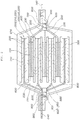
- FIG. 2 is a view illustrating a structure of a lithium ion secondary battery according to an exemplary embodiment of the present disclosure.
- FIG. 3 is a flowchart illustrating a manufacturing method of a lithium ion secondary battery according to an exemplary embodiment of the present disclosure
- FIG. 4 is a view for describing the manufacturing method of a lithium ion secondary battery according to an exemplary embodiment of the present disclosure
- FIG. 5 is a view for describing a manufacturing method of a lithium ion secondary battery according to another exemplary embodiment of the present disclosure
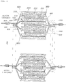
- FIG. 6 is a view illustrating figures before and after charging of the lithium ion secondary battery manufactured according to the manufacturing method of a lithium ion secondary battery according to an exemplary embodiment of the present disclosure.
- a lithium ion secondary battery may include cathodes 100, anodes 200, separation membranes 300, first bent portions 400, second bent portions 500, and a first overlapping portion 600, and may further include third bent portions 800, fourth bent portions 900, and a second overlapping portion 950. Further, the lithium ion secondary battery may further include a case 970 covering an assembled battery cell.
- the cathode 100 may include a cathode current collector 110, a cathode coating layer 120 coating the cathode current collector 110, and a cathode lead 130.
- any cathode current collector 110 may be used as long as it is a conductor and is electrochemically stable within the range of use, and the cathode current collector 110 may be aluminum, stainless steel, nickel plated steel, or the like according to an exemplary embodiment.
- the cathode coating layer 120 may include a cathode active material layer formed on the cathode current collector 110 and including a cathode active material, and a coating layer formed on the cathode active material layer and including a conductive material and a binder.
- the cathode active material is a solid solution oxide including lithium according to an exemplary embodiment, but is not particularly limited as long as it is a material capable of electrochemically occluding and releasing lithium ions.
- the cathode lead 130 is a portion where the cathode coating layer 120 is not formed on the cathode current collector 110 and is welded with a cathode lead tab to serve to flow electricity to the outside.
- the anode 200 may include an anode current collector 210, an anode coating layer 220 coating the anode current collector 210, and an anode lead 230.
- any anode current collector 210 may be used as long as it is a conductor and is electrochemically stable within the range of use, and the anode current collector 210 may be copper, aluminum, stainless steel, nickel plated steel, or the like according to an exemplary embodiment, but is not limited thereto.
- the anode coating layer 220 may include an anode active material layer formed on some regions on the anode current collector 210 and including an anode active material, and a coating layer formed on the anode active material layer and including one or more of a conductive material and a binder.
- the anode active material may include a metal-based active material and a carbon-based active material, where the metal-based active material may include a silicon-based active material, a tin-based active material, or a combination thereof, and the carbon-based active material is a material including carbon (atoms) and capable of electrochemically occluding and releasing lithium ions at the same time and may be a graphite active material, artificial graphite, natural graphite, a mixture of artificial graphite and natural graphite, natural graphite coated with artificial graphite, and the like, but is not limited thereto.
- the anode lead 230 is a portion where the anode coating layer 220 is not formed on the anode current collector 210 and is welded with an anode lead tab to serve to flow electricity to the outside.
- the separation membrane 300 is positioned between the cathode 100 and the anode 200 to serve to electrically separate the cathode 100 and the anode 200, and may be formed as a porous membrane through which ions may move between the cathode 100 and the anode 200.
- first bent portions 400, the second bent portions 500, the first overlapping portion 600, the third bent portions 800, the fourth bent portions 900, and the second overlapping portion 950 which are essential characteristics of the present disclosure, will be described in detail.
- the first bent portions 400 refer to portions where a plurality of cathode leads 130 are bent at a point spaced apart from the cathode coating layer 120 by a predetermined distance. In this case, it is preferable to form the first bent portions 400 to be spaced apart from the outermost positioned one of the cathode 100, the anode 200, and the separation membrane 300. In FIG. 2 , since the separation membrane 300 of the cathode 100, the anode 200, and the separation membrane 300 is positioned at the outermost side, it is preferable to form the first bent portions 400 to be spaced apart from the separation membrane 300 by a predetermined distance. As will be described later in a manufacturing method of a lithium ion secondary battery according to an exemplary embodiment of the present disclosure, a shape and a formation position of the first bent portion 400 may be more precisely adjusted by using support pins 20 according to an exemplary embodiment.
- the second bent portions 500 may refer to portions where the plurality of cathode leads 130 are bent at points where the plurality of cathode leads 130 bent at the first bent portions 400 meet
- the first overlapping portion 600 may refer to a portion where the plurality of cathode leads 130 bent at the second bent portions 500 overlap in parallel.
- the first overlapping portion 600 may be in a state in which only a portion thereof is welded from end portions of the plurality of cathode leads 130 overlapping in parallel and the remaining portion thereof is not welded.
- the first overlapping portion 600 may include a first welded portion 610 to which the plurality of cathode leads 130 are welded and a first non-welded portion 620 to which the plurality of cathode leads 130 are not welded.
- the first non-welded portion 620 may be formed between the first welded portion 610 and the second bent portions 500, and according to an exemplary embodiment, a length of the first non-welded portion 620 is preferably formed of 2 mm or more.
- the lithium ion secondary battery according to an exemplary embodiment of the present disclosure may further include a cathode tab welding portion 700.
- the cathode tab welding portion 700 refers to a portion where the first welded portion 610 and a cathode tab 140 are welded.
- the cathode tab 140 as an end tab of the cathode side of the lithium ion secondary battery, may be disposed on one end of the battery.
- a portion of the cathode tab 140 may be covered by the case 970 and another portion thereof may extend to outside of the battery for an electrical connection.
- the second bent portions 500 described above are preferably formed to be spaced apart from an end portion of the cathode tab welding portion 700 by a predetermined distance.
- the third bent portions 800 refer to portions in which a plurality of anode leads 230 are bent at points spaced apart from the anode coating layer 220 by a predetermined distance. In this case, it is preferable to form the third bent portions 800 to be spaced apart from the outermost positioned one of the cathode 100, the anode 200, and the separation membrane 300. In FIG. 2 , since the separation membrane 300 of the cathode 100, the anode 200, and the separation membrane 300 is positioned at the outermost side, it is preferable to form the third bent portions 800 to be spaced apart from the separation membrane 300 by a predetermined distance. As will be described later in a manufacturing method of a lithium ion secondary battery according to an exemplary embodiment of the present disclosure, a shape and a formation position of the third bent portion 800 may be more precisely adjusted by using support pins 20 according to an exemplary embodiment.
- the fourth bent portions 900 may refer to portions where the plurality of anode leads 230 are bent at points where the plurality of anode leads 230 bent at the third bent portions 300 meet, and the second overlapping portion 950 may refer to a portion where the plurality of anode leads 230 bent at the fourth bent portions 900 overlap in parallel.
- the second overlapping portion 950 may be in a state in which only a portion thereof is welded from end portions of the plurality of anode leads 230 overlapping in parallel and the remaining portion thereof is not welded.
- the second overlapping portion 950 may include a second welded portion 951 to which the plurality of anode leads 230 are welded and a second non-welded portion 952 to which the plurality of anode leads 230 are not welded.
- the second non-welded portion 952 may be formed between the second welded portion 951 and the fourth bent portions 900, and according to an exemplary embodiment, a length of the second non-welded portion 952 is preferably formed of 2 mm or more.
- the lithium ion secondary battery according to an exemplary embodiment of the present disclosure may further include an anode tab welding portion 960.
- the anode tab welding portion 960 refers to a portion where the second welded portion 951 and an anode tab 240 are welded.
- the anode tab 240 as an end tab of the anode side of the lithium ion secondary battery, may be disposed on another end of the battery opposite to the cathode tab 140.
- a portion of the anode tab 240 may be covered by the case 970 and another portion thereof may extend to outside of the battery for an electrical connection.
- the fourth bent portions 950 described above are preferably formed to be spaced apart from an end portion of the anode tab welding portion 960 by a predetermined distance.
- the lithium ion secondary battery according to an exemplary embodiment of the present disclosure includes the second bent portions and the first overlapping portion, in which the first non-welded portion and the second bent portions are unfolded when the electrode swells after the battery cell is charged by forming the first non-welded portion on the first overlapping portion. Therefore, unlike the related art, interference between the cathode lead and the anode may be prevented, and the damage to the anode and ignition that may occur due to a short circuit between the cathode lead and the anode may be prevented, thereby improving stability of the cell.
- a manufacturing method of a lithium ion secondary battery may include an operation (S100) of stacking a plurality of anodes, a plurality of separation membranes, and a plurality of cathodes, an operation (S200) of forming a first overlapping portion by pressing and bending a plurality of cathode leads stacked at points spaced apart from a cathode coating layer by a first predetermined distance and overlapping and fixing the plurality of cathode leads in parallel at a point where the plurality of bent cathode leads meet, and an operation (S300) of welding only a portion of the first overlapping portion from end portions of the plurality of cathode leads.
- S100 operation of stacking a plurality of anodes, a plurality of separation membranes, and a plurality of cathodes
- the operation (S200) of forming a first overlapping portion by pressing and bending a plurality of cathode leads stacked at points spaced apart from a cathode coating layer by a first predetermined distance and overlapping and fixing the plurality of cathode leads in parallel at a point where the plurality of bent cathode leads meet may include an operation (S210) of simultaneously pressing and bending the plurality of cathode leads stacked in parallel from the top and bottom using a pair of lead fixing jigs 10 at points spaced apart from the cathode coating layer by a first predetermined distance and operation (S220) of overlapping and fixing the plurality of cathode leads in parallel by pressing the plurality of bent cathode leads using the pair of lead fixing jigs until the plurality of bent cathode leads meet.
- the operation (S200) of forming a first overlapping portion by pressing and bending a plurality of cathode leads stacked at points spaced apart from a cathode coating layer by a first predetermined distance and overlapping and fixing the plurality of cathode leads in parallel at a point where the plurality of bent cathode leads meet may include an operation (S230) of simultaneously pressing and bending the plurality of cathode leads stacked in parallel from the top and bottom using a pair of lead fixing jigs including an air nozzle at points spaced apart from the cathode coating layer by a first predetermined distance and operation (S240) of overlapping and fixing the plurality of cathode leads in parallel by pressing the plurality of bent cathode leads using the pair of lead fixing jigs including the air nozzle until the plurality of bent cathode leads meet.
- the operation (S200) of forming a first overlapping portion by pressing and bending a plurality of cathode leads stacked at points spaced apart from a cathode coating layer by a first predetermined distance and overlapping and fixing the plurality of cathode leads in parallel at a point where the plurality of bent cathode leads meet may include an operation (S250) of simultaneously pressing and bending the plurality of cathode leads stacked in parallel from the top and bottom using a pair of lead fixing jigs including a plurality of air nozzles at points spaced apart from the cathode coating layer by a first predetermined distance and an operation (S260) of overlapping and fixing the plurality of cathode leads in parallel by pressing the plurality of bent cathode leads using the pair of lead fixing jigs including the plurality of air nozzles until the plurality of bent cathode leads meet.
- the operation (S250) of simultaneously pressing and bending the plurality of cathode leads stacked in parallel from the top and bottom using a pair of lead fixing jigs including a plurality of air nozzles at points spaced apart from the cathode coating layer by a first predetermined distance may include an operation (S251) of raising and lowering the pair of lead fixing jigs by a predetermined distance as air is ejected obliquely to the outermost side from an air nozzle located at the outermost side of the plurality of air nozzles and an operation (S252) of ejecting air from an air nozzle located at the innermost side after raising and lowering the pair of lead fixing jigs by the predetermined distance.
- the lead fixing jig 10 may include a first air nozzle 11 and a second air nozzle 12, and according to an exemplary embodiment, the first air nozzle 11 may be the air nozzle located at the outermost side and the second air nozzle 12 may be the air nozzle located at the innermost side.
- the air nozzles may serve as the air nozzle located at the outermost side and the air nozzle located at the innermost side, the positions of the first air nozzles 11 and the second air nozzles 12 may be changed according to the exemplary embodiment.
- the manufacturing method of a lithium ion secondary battery may further include an operation (S120) of inserting support pins 20 in a direction perpendicular to the cathode leads in a direction in which the cathode leads are bent at points spaced apart from the cathode coating layer by a second predetermined distance, before the operation of simultaneously pressing and bending the plurality of cathode leads stacked in parallel from the top and bottom using a pair of lead fixing jigs including a plurality of air nozzles at points spaced apart from the cathode coating layer by a first predetermined distance.
- the manufacturing method of a lithium ion secondary battery includes the operation (S120) of inserting support pins 20 in a direction perpendicular to the cathode leads in a direction in which the cathode leads are bent at points spaced apart from the cathode coating layer by a second predetermined distance, before the operation of simultaneously pressing and bending the plurality of cathode leads stacked in parallel from the top and bottom using a pair of lead fixing jigs including a plurality of air nozzles at points spaced apart from the cathode coating layer by a first predetermined distance, whereby a shape and a formation position of the first bent portion may be more finely adjusted and interference between the cathode lead and the anode may be thus prevented when the electrode swells after the lithium ion secondary battery is charged, thereby more improving stability of a cell.
- the manufacturing method of a lithium ion secondary battery according to an exemplary embodiment of the present disclosure may further include an operation (S400) of forming a second overlapping portion by pressing and bending a plurality of anode leads stacked at points spaced apart from an anode coating layer by a first predetermined distance and overlapping and fixing the plurality of anode leads in parallel at a point where the plurality of bent anode leads meet and an operation (S500) of welding only a portion of the second overlapping portion from end portions of the plurality of anode leads.
- S400 operation of forming a second overlapping portion by pressing and bending a plurality of anode leads stacked at points spaced apart from an anode coating layer by a first predetermined distance and overlapping and fixing the plurality of anode leads in parallel at a point where the plurality of bent anode leads meet
- an operation (S500) of welding only a portion of the second overlapping portion from end portions of the plurality of anode leads may further include an operation (
- the operation (S400) of forming a second overlapping portion by pressing and bending a plurality of anode leads stacked at points spaced apart from an anode coating layer by a first predetermined distance and overlapping and fixing the plurality of anode leads in parallel at a point where the plurality of bent anode leads meet may include an operation (S410) of simultaneously pressing and bending the plurality of anode leads stacked in parallel from the top and bottom using a pair of lead fixing jigs including an air nozzle at points spaced apart from the anode coating layer by a first predetermined distance and an operation (S420) of overlapping and fixing the plurality of anode leads in parallel by pressing the plurality of bent anode leads using the pair of lead fixing jigs until the plurality of bent anode leads meet.
- the operation (S400) of forming a second overlapping portion by pressing and bending a plurality of anode leads stacked at points spaced apart from an anode coating layer by a first predetermined distance and overlapping and fixing the plurality of anode leads in parallel at a point where the plurality of bent anode leads meet may include an operation (S430) of simultaneously pressing and bending the plurality of anode leads stacked in parallel from the top and bottom using a pair of lead fixing jigs including a plurality of air nozzles at points spaced apart from the anode coating layer by a first predetermined distance and an operation (S440) of overlapping and fixing the plurality of anode leads in parallel by pressing the plurality of bent anode leads using the pair of lead fixing jigs until the plurality of bent anode leads meet.
- the operation (S430) of simultaneously pressing and bending the plurality of anode leads stacked in parallel from the top and bottom using a pair of lead fixing jigs including a plurality of air nozzles at points spaced apart from the anode coating layer by a first predetermined distance may include an operation (S431) of raising and lowering the pair of lead fixing jigs by a predetermined distance as the air is ejected obliquely to the outermost side from an air nozzle located at the outermost side of the plurality of air nozzles and an operation (S432) of ejecting the air from an air nozzle located at the innermost side after raising and lowering the pair of lead fixing jigs by the predetermined distance.
- the manufacturing method of a lithium ion secondary battery may further include an operation of inserting support pins 20 in a direction perpendicular to the anode leads in a direction in which the anode leads are bent at points spaced apart from the anode coating layer by a second predetermined distance, before the operation of simultaneously pressing and bending the plurality of anode leads stacked in parallel from the top and bottom using a pair of lead fixing jigs including a plurality of air nozzles at points spaced apart from the anode coating layer by a first predetermined distance.
- the manufacturing method of a lithium ion secondary battery according to the present disclosure further includes the operation of inserting support pins 20 in a direction perpendicular to the anode leads in a direction in which the anode leads are bent at points spaced apart from the anode coating layer by a second predetermined distance, before the operation of simultaneously pressing and bending the plurality of anode leads stacked in parallel from the top and bottom using a pair of lead fixing jigs including a plurality of air nozzles at points spaced apart from the anode coating layer by a first predetermined distance, whereby a shape and a formation position of the third bent portion may be more finely adjusted and the stability of the cell may be improved when the electrode swells after the lithium ion secondary battery is charged.
- only the portions from the end portions of the plurality of cathode leads and anode leads may be welded through an ultrasonic welder according to an exemplary embodiment.
- an elastic material may be attached to a surface of the lead fixing jig 10 used in the manufacturing method of a lithium ion secondary battery according to the present disclosure in contact with the cathode lead and the anode lead.
- the elastic material may absorb vibration generated by an ultrasonic welder, thereby preventing the vibration from propagating into the electrode and minimizing the dropping of the active material coated on the electrode.
- the manufacturing method of a lithium ion secondary battery may further include, after welding only the portion of the first overlapping portion from the end portions of the plurality of cathode leads and welding only the portion of the second overlapping portion from the end portions of the plurality of anode leads, an operation of forming a cathode tab welded portion by welding a welded portion of the first overlapping portion and a cathode tab, and an operation of forming an anode tab welded portion by welding a welded portion of the second overlapping portion and an anode tab.
- the manufacturing method of a lithium ion secondary battery may further include an operation of covering a battery cell with the case 970 after an assembly of the battery cell is completed.
- the manufacturing method of a lithium ion secondary battery according to the present disclosure described above has the following effects.
- the lead fixing jip is raised and lowered while ejecting the air and generates the vibration in the cathode lead and the anode lead, and the generated vibration is propagated into the electrode to minimize friction force between the leads, thereby making it possible to minimizing deformation of the electrode.
- the lead fixing jig is raised and lowered while ejecting the air to minimize friction force between the leads, thereby making it possible to minimizing deformation of the electrode when the cathode lead and the anode lead are bent.
- the cathode lead and the anode lead may be bent the positions farther from the electrode, thereby forming the non-welded portion sections with a margin.
Landscapes
- Chemical & Material Sciences (AREA)
- Chemical Kinetics & Catalysis (AREA)
- Electrochemistry (AREA)
- General Chemical & Material Sciences (AREA)
- Engineering & Computer Science (AREA)
- Manufacturing & Machinery (AREA)
- Materials Engineering (AREA)
- Secondary Cells (AREA)
- Connection Of Batteries Or Terminals (AREA)
Abstract
Description
- The present disclosure relates to a lithium ion secondary battery and a manufacturing method of the same, and more particularly, to a lithium ion secondary battery capable of increasing energy density and improving stability of a cell by forming non-welded portions having a predetermined length on a cathode lead and an anode lead.
- Recently, the application of lithium ion battery cells to electric vehicles is expanding, and the demand for high energy density battery cells is increasing to improve one-charging mileage of electric vehicles. In this regard, conventionally, the development is in progress toward designing a cell thickness to be thick, reducing a thickness of an electrode substrate, and reducing a space of a terrace portion in a tab direction in order to increase the number of electrode stacks and current density to increase energy density of the battery cells.
-
FIG. 1 is a view illustrating that interference between a cathode lead portion and an anode occurs when an electrode swells after a conventional lithium ion secondary battery is charged. As such, in the conventional lithium ion secondary battery, there was a problem in that the anode may be damaged due to the interference between the cathode lead portion and the anode when the electrode swells after the conventional lithium ion secondary battery is charged, and there was also a problem in that a short circuit between the cathode lead portion and the anode may occur to cause ignition. - The above information disclosed in this Background section is only for enhancement of understanding of the background of the present disclosure, and should not be taken as acknowledgement that this information forms the prior art that is already known to a person skilled in the art.
- An object of the present disclosure is to provide a lithium ion secondary battery capable of increasing energy density and simultaneously improving stability of a cell by non-welded portions serving as a buffer when an electrode swells after charging, by forming the non-welded portions having a predetermined length on a cathode lead and an anode lead, and a manufacturing method of the same.
- According to an exemplary embodiment of the present disclosure, a lithium ion secondary battery includes: a plurality of cathodes each including a cathode current collector, a cathode coating layer coating the cathode current collector, and a cathode lead; a plurality of anodes each including an anode current collector, an anode coating layer coating the anode current collector, and an anode lead; and a plurality of separation membranes arranged between the plurality of cathodes and the plurality of anodes, respectively. A plurality of cathode leads among the plurality of cathodes include first bent portions, respectively, at first points spaced apart from respective cathode coating layers by a predetermined distance. The plurality of cathode leads further include second bent portions, respectively, at second points where the plurality of cathode leads meet. The lithium ion secondary battery further includes a first overlapping portion at which the plurality of cathode leads overlap in parallel. The first overlapping portion includes a first welded portion to which the plurality of cathode leads are welded and a first non-welded portion to which the plurality of cathode leads are not welded.
- The first welded portion is welded to end portions of the plurality of cathode leads overlapping in parallel and a remaining portion of the first overlapping portion is not welded to the end portions of the plurality of cathode leads.
- The lithium ion secondary battery may further include a cathode tab disposed on a first end portion of the lithium ion secondary battery, wherein the first welded portion and the cathode tab are welded to each other at a cathode tab welded portion disposed therebetween, and wherein the second bent portions are spaced apart from an end of the cathode tab welded portion by a predetermined distance.
- The first non-welded portion is arranged between the first welded portion and the second bent portions, and a length of the first non-welded portion may be 2 mm or more.
- The first bent portions are spaced apart from an outermost one of the plurality of cathodes, the plurality of separation membranes, and the plurality of anodes.
- A plurality of anode leads among the plurality of anodes include third bent portions, respectively, at third points spaced apart from respective anode coating layers by a predetermined distance. The plurality of anode leads further include fourth bent portions, respectively, at fourth points where the plurality of anode leads meet. The lithium ion secondary battery further includes a second overlapping portion where the plurality of anode leads at the fourth points overlap in parallel. The second overlapping portion includes a second welded portion to which the plurality of anode leads are welded and a second non-welded portion to which the plurality of anode leads are not welded.
- The second welded portion is welded to end portions of the plurality of anode leads overlapping in parallel and a remaining portion of the second overlapping portion is not welded to the end portions of the plurality of anode leads.
- The lithium ion secondary battery may further include an anode tab disposed on a second end portion of the lithium ion secondary battery, wherein the second welded portion and the anode tab are welded to each other at an anode tab welded portion disposed therebetween, and wherein the fourth bent portions are spaced apart from an end of the anode tab welded portion by a predetermined distance.
- The second non-welded portion is arranged between the second welded portion and the fourth bent portions, and a length of the second non-welded portion may be 2 mm or more.
- The third bent portions are spaced apart from an outermost one of the plurality of anodes, the plurality of separation membranes, and the plurality of cathodes.
- According to another exemplary embodiment of the present disclosure, a manufacturing method of a lithium ion secondary battery includes steps of: stacking a plurality of anodes, a plurality of separation membranes, and a plurality of cathodes; forming a first overlapping portion by pressing and bending a plurality of cathode leads at first points spaced apart from respective cathode coating layers by a first predetermined distance and by overlapping and fixing the plurality of cathode leads in parallel at second points where the plurality of bent cathode leads meet; and welding a portion of the first overlapping portion to end portions of the plurality of cathode leads.
- The step of forming a first overlapping portion includes steps of: simultaneously pressing and bending the plurality of cathode leads stacked in parallel from the top and bottom using a pair of lead fixing jigs at the first points spaced apart from the respective cathode coating layers by the first predetermined distance; and overlapping and fixing the plurality of cathode leads in parallel by pressing the plurality of bent cathode leads using the pair of lead fixing jigs until the plurality of cathode leads meet.
- The step of forming a first overlapping portion includes steps of: simultaneously pressing and bending the plurality of cathode leads stacked in parallel from the top and bottom using a pair of lead fixing jigs including an air nozzle at the first points spaced apart from the respective cathode coating layers by the first predetermined distance; and overlapping and fixing the plurality of cathode leads in parallel by pressing the plurality of bent cathode leads using the pair of lead fixing jigs until the plurality of cathode leads meet.
- The step of forming a first overlapping portion includes steps of: simultaneously pressing and bending the plurality of cathode leads stacked in parallel from the top and bottom using a pair of lead fixing jigs including a plurality of air nozzles at the first points spaced apart from the respective cathode coating layers by the first predetermined distance; and overlapping and fixing the plurality of cathode leads in parallel by pressing the plurality of bent cathode leads using the pair of lead fixing jigs until the plurality of cathode leads meet.
- The step of simultaneously pressing and bending the plurality of cathode leads stacked in parallel from the top and bottom using a pair of lead fixing jigs including a plurality of air nozzles includes steps of: raising and lowering the pair of lead fixing jigs by a predetermined distance as air is ejected obliquely to an outermost side of the plurality of air nozzles from an air nozzle located at the outermost side of the plurality of air nozzles; and ejecting air from an air nozzle located at an innermost side of the plurality of air nozzles after raising and lowering the pair of lead fixing jigs by the predetermined distance.
- The manufacturing method of a lithium ion secondary battery may further include a step of: before the step of simultaneously pressing and bending the plurality of cathode leads stacked in parallel from the top and bottom using a pair of lead fixing jigs including a plurality of air nozzles, inserting support pins in a direction perpendicular to the plurality of cathode leads in a direction in which the plurality of cathode leads are bent at points spaced apart from the respective cathode coating layers by a predetermined distance.
- The manufacturing method of a lithium ion secondary battery may further include steps of: forming a second overlapping portion by pressing and bending a plurality of anode leads at points spaced apart from respective anode coating layers by the first predetermined distance and overlapping and fixing the plurality of anode leads in parallel at a point where the plurality of bent anode leads meet; and welding a portion of the second overlapping portion to end portions of the plurality of anode leads.
- The step of forming a second overlapping portion includes steps of: simultaneously pressing and bending the plurality of anode leads stacked in parallel from the top and bottom using a pair of lead fixing jigs including an air nozzle at points spaced apart from the respective anode coating layers by the first predetermined distance; and overlapping and fixing the plurality of anode leads in parallel by pressing the plurality of bent cathode leads using the pair of lead fixing jigs until the plurality of bent cathode leads meet.
- The step of forming a second overlapping portion includes steps of: simultaneously pressing and bending the plurality of anode leads stacked in parallel from the top and bottom using a pair of lead fixing jigs including a plurality of air nozzles at points spaced apart from the respective anode coating layers by the first predetermined distance; and overlapping and fixing the plurality of anode leads in parallel by pressing the plurality of bent cathode leads using the pair of lead fixing jigs until the plurality of bent cathode leads meet.
- The step of simultaneously pressing and bending the plurality of anode leads stacked in parallel from the top and bottom using a pair of lead fixing jigs including a plurality of air nozzles includes: raising and lowering the pair of lead fixing jigs by a predetermined distance as air is ejected obliquely to an outermost side of the plurality of air nozzles from an air nozzle located at the outermost side of the plurality of air nozzles; and ejecting air from an air nozzle located at an innermost side of the plurality of air nozzles after raising and lowering the pair of lead fixing jigs by the predetermined distance.
- The manufacturing method of a lithium ion secondary battery may further include: before the step of simultaneously pressing and bending the plurality of anode leads stacked in parallel from the top and bottom using a pair of lead fixing jigs including a plurality of air nozzles, inserting support pins in a direction perpendicular to the anode leads in a direction in which the plurality of anode leads are bent at points spaced apart from the respective anode coating layers by a predetermined distance.
-
-
FIG. 1 is a view illustrating that interference between a cathode lead portion and an anode occurs when an electrode swells after a conventional lithium ion secondary battery is charged. -
FIG. 2 is a view illustrating a structure of a lithium ion secondary battery according to an exemplary embodiment of the present disclosure. -
FIG. 3 is a flowchart illustrating a manufacturing method of a lithium ion secondary battery according to an exemplary embodiment of the present disclosure. -
FIG. 4 is a view for describing the manufacturing method of a lithium ion secondary battery according to an exemplary embodiment of the present disclosure. -
FIG. 5 is a view for describing a manufacturing method of a lithium ion secondary battery according to another exemplary embodiment of the present disclosure. -
FIG. 6 is a view illustrating figures before and after charging of the lithium ion secondary battery manufactured according to the manufacturing method of a lithium ion secondary battery according to an exemplary embodiment of the present disclosure. - Hereinafter, the present disclosure will be described in detail with reference to the drawings. Terms and words used in the present specification and claims are not to be construed as a general or dictionary meaning but are to be construed as meaning and concepts meeting the technical ideas of the present disclosure based on a principle that the inventor can appropriately define the concepts of terms in order to describe their own disclosure in best mode.
- Therefore, configurations described in embodiments and the accompanying drawings of the present disclosure do not represent all of the technical spirits of the present disclosure, but are merely most preferable embodiments. Therefore, the present disclosure should be construed as including all the changes, equivalents, and substitutions included in the spirit and scope of the present disclosure at the time of filing the application.
-
FIG. 2 is a view illustrating a structure of a lithium ion secondary battery according to an exemplary embodiment of the present disclosure. In addition,FIG. 3 is a flowchart illustrating a manufacturing method of a lithium ion secondary battery according to an exemplary embodiment of the present disclosure,FIG. 4 is a view for describing the manufacturing method of a lithium ion secondary battery according to an exemplary embodiment of the present disclosure,FIG. 5 is a view for describing a manufacturing method of a lithium ion secondary battery according to another exemplary embodiment of the present disclosure, andFIG. 6 is a view illustrating figures before and after charging of the lithium ion secondary battery manufactured according to the manufacturing method of a lithium ion secondary battery according to an exemplary embodiment of the present disclosure. - As illustrating in
FIG. 2 , a lithium ion secondary battery according to an exemplary embodiment of the present disclosure may include cathodes 100,anodes 200,separation membranes 300,first bent portions 400,second bent portions 500, and a first overlappingportion 600, and may further includethird bent portions 800,fourth bent portions 900, and a second overlappingportion 950. Further, the lithium ion secondary battery may further include acase 970 covering an assembled battery cell. - The cathode 100 may include a cathode
current collector 110, acathode coating layer 120 coating the cathodecurrent collector 110, and acathode lead 130. Here, any cathodecurrent collector 110 may be used as long as it is a conductor and is electrochemically stable within the range of use, and the cathodecurrent collector 110 may be aluminum, stainless steel, nickel plated steel, or the like according to an exemplary embodiment. - In addition, the
cathode coating layer 120 may include a cathode active material layer formed on the cathodecurrent collector 110 and including a cathode active material, and a coating layer formed on the cathode active material layer and including a conductive material and a binder. Here, the cathode active material is a solid solution oxide including lithium according to an exemplary embodiment, but is not particularly limited as long as it is a material capable of electrochemically occluding and releasing lithium ions. - The
cathode lead 130 is a portion where thecathode coating layer 120 is not formed on the cathodecurrent collector 110 and is welded with a cathode lead tab to serve to flow electricity to the outside. - The
anode 200 may include an anodecurrent collector 210, ananode coating layer 220 coating the anodecurrent collector 210, and ananode lead 230. Here, any anodecurrent collector 210 may be used as long as it is a conductor and is electrochemically stable within the range of use, and the anodecurrent collector 210 may be copper, aluminum, stainless steel, nickel plated steel, or the like according to an exemplary embodiment, but is not limited thereto. - The
anode coating layer 220 may include an anode active material layer formed on some regions on the anodecurrent collector 210 and including an anode active material, and a coating layer formed on the anode active material layer and including one or more of a conductive material and a binder. The anode active material may include a metal-based active material and a carbon-based active material, where the metal-based active material may include a silicon-based active material, a tin-based active material, or a combination thereof, and the carbon-based active material is a material including carbon (atoms) and capable of electrochemically occluding and releasing lithium ions at the same time and may be a graphite active material, artificial graphite, natural graphite, a mixture of artificial graphite and natural graphite, natural graphite coated with artificial graphite, and the like, but is not limited thereto. - The
anode lead 230 is a portion where theanode coating layer 220 is not formed on the anodecurrent collector 210 and is welded with an anode lead tab to serve to flow electricity to the outside. - The
separation membrane 300 is positioned between the cathode 100 and theanode 200 to serve to electrically separate the cathode 100 and theanode 200, and may be formed as a porous membrane through which ions may move between the cathode 100 and theanode 200. - Hereinafter, the first
bent portions 400, the secondbent portions 500, the first overlappingportion 600, the thirdbent portions 800, the fourthbent portions 900, and the second overlappingportion 950, which are essential characteristics of the present disclosure, will be described in detail. - Referring to
FIG. 2 , the firstbent portions 400 refer to portions where a plurality of cathode leads 130 are bent at a point spaced apart from thecathode coating layer 120 by a predetermined distance. In this case, it is preferable to form the firstbent portions 400 to be spaced apart from the outermost positioned one of the cathode 100, theanode 200, and theseparation membrane 300. InFIG. 2 , since theseparation membrane 300 of the cathode 100, theanode 200, and theseparation membrane 300 is positioned at the outermost side, it is preferable to form the firstbent portions 400 to be spaced apart from theseparation membrane 300 by a predetermined distance. As will be described later in a manufacturing method of a lithium ion secondary battery according to an exemplary embodiment of the present disclosure, a shape and a formation position of the firstbent portion 400 may be more precisely adjusted by using support pins 20 according to an exemplary embodiment. - Referring to
FIG. 2 , the secondbent portions 500 may refer to portions where the plurality of cathode leads 130 are bent at points where the plurality of cathode leads 130 bent at the firstbent portions 400 meet, and the first overlappingportion 600 may refer to a portion where the plurality of cathode leads 130 bent at the secondbent portions 500 overlap in parallel. Here, the first overlappingportion 600 may be in a state in which only a portion thereof is welded from end portions of the plurality of cathode leads 130 overlapping in parallel and the remaining portion thereof is not welded. - Specifically, the first overlapping
portion 600 may include a first weldedportion 610 to which the plurality of cathode leads 130 are welded and a firstnon-welded portion 620 to which the plurality of cathode leads 130 are not welded. Here, the firstnon-welded portion 620 may be formed between the first weldedportion 610 and the secondbent portions 500, and according to an exemplary embodiment, a length of the firstnon-welded portion 620 is preferably formed of 2 mm or more. - The lithium ion secondary battery according to an exemplary embodiment of the present disclosure may further include a cathode
tab welding portion 700. Here, the cathodetab welding portion 700 refers to a portion where the first weldedportion 610 and acathode tab 140 are welded. Thecathode tab 140, as an end tab of the cathode side of the lithium ion secondary battery, may be disposed on one end of the battery. A portion of thecathode tab 140 may be covered by thecase 970 and another portion thereof may extend to outside of the battery for an electrical connection. The secondbent portions 500 described above are preferably formed to be spaced apart from an end portion of the cathodetab welding portion 700 by a predetermined distance. - The third
bent portions 800 refer to portions in which a plurality of anode leads 230 are bent at points spaced apart from theanode coating layer 220 by a predetermined distance. In this case, it is preferable to form the thirdbent portions 800 to be spaced apart from the outermost positioned one of the cathode 100, theanode 200, and theseparation membrane 300. InFIG. 2 , since theseparation membrane 300 of the cathode 100, theanode 200, and theseparation membrane 300 is positioned at the outermost side, it is preferable to form the thirdbent portions 800 to be spaced apart from theseparation membrane 300 by a predetermined distance. As will be described later in a manufacturing method of a lithium ion secondary battery according to an exemplary embodiment of the present disclosure, a shape and a formation position of the thirdbent portion 800 may be more precisely adjusted by using support pins 20 according to an exemplary embodiment. - Referring to
FIG. 2 , the fourthbent portions 900 may refer to portions where the plurality of anode leads 230 are bent at points where the plurality of anode leads 230 bent at the thirdbent portions 300 meet, and the second overlappingportion 950 may refer to a portion where the plurality of anode leads 230 bent at the fourthbent portions 900 overlap in parallel. Here, the second overlappingportion 950 may be in a state in which only a portion thereof is welded from end portions of the plurality of anode leads 230 overlapping in parallel and the remaining portion thereof is not welded. - Specifically, the second overlapping
portion 950 may include a second weldedportion 951 to which the plurality of anode leads 230 are welded and a secondnon-welded portion 952 to which the plurality of anode leads 230 are not welded. Here, the secondnon-welded portion 952 may be formed between the second weldedportion 951 and the fourthbent portions 900, and according to an exemplary embodiment, a length of the secondnon-welded portion 952 is preferably formed of 2 mm or more. - The lithium ion secondary battery according to an exemplary embodiment of the present disclosure may further include an anode
tab welding portion 960. Here, the anodetab welding portion 960 refers to a portion where the second weldedportion 951 and ananode tab 240 are welded. Theanode tab 240, as an end tab of the anode side of the lithium ion secondary battery, may be disposed on another end of the battery opposite to thecathode tab 140. A portion of theanode tab 240 may be covered by thecase 970 and another portion thereof may extend to outside of the battery for an electrical connection. The fourthbent portions 950 described above are preferably formed to be spaced apart from an end portion of the anodetab welding portion 960 by a predetermined distance. - Compared with the conventional lithium ion secondary battery, the effect of the lithium ion secondary battery according to the present disclosure is described with reference to
FIG. 6 as follows. - As described above, the lithium ion secondary battery according to an exemplary embodiment of the present disclosure includes the second bent portions and the first overlapping portion, in which the first non-welded portion and the second bent portions are unfolded when the electrode swells after the battery cell is charged by forming the first non-welded portion on the first overlapping portion. Therefore, unlike the related art, interference between the cathode lead and the anode may be prevented, and the damage to the anode and ignition that may occur due to a short circuit between the cathode lead and the anode may be prevented, thereby improving stability of the cell.
- Hereinafter, a manufacturing method of a lithium ion secondary battery according to an exemplary embodiment of the present disclosure will be described with reference to
FIGS. 3 to 5 . - As illustrated in
FIG. 3 , a manufacturing method of a lithium ion secondary battery according to an exemplary embodiment of the present disclosure may include an operation (S100) of stacking a plurality of anodes, a plurality of separation membranes, and a plurality of cathodes, an operation (S200) of forming a first overlapping portion by pressing and bending a plurality of cathode leads stacked at points spaced apart from a cathode coating layer by a first predetermined distance and overlapping and fixing the plurality of cathode leads in parallel at a point where the plurality of bent cathode leads meet, and an operation (S300) of welding only a portion of the first overlapping portion from end portions of the plurality of cathode leads. - Specifically, the operation (S200) of forming a first overlapping portion by pressing and bending a plurality of cathode leads stacked at points spaced apart from a cathode coating layer by a first predetermined distance and overlapping and fixing the plurality of cathode leads in parallel at a point where the plurality of bent cathode leads meet may include an operation (S210) of simultaneously pressing and bending the plurality of cathode leads stacked in parallel from the top and bottom using a pair of
lead fixing jigs 10 at points spaced apart from the cathode coating layer by a first predetermined distance and operation (S220) of overlapping and fixing the plurality of cathode leads in parallel by pressing the plurality of bent cathode leads using the pair of lead fixing jigs until the plurality of bent cathode leads meet. - Referring to
FIG. 4 , according to an exemplary embodiment, the operation (S200) of forming a first overlapping portion by pressing and bending a plurality of cathode leads stacked at points spaced apart from a cathode coating layer by a first predetermined distance and overlapping and fixing the plurality of cathode leads in parallel at a point where the plurality of bent cathode leads meet may include an operation (S230) of simultaneously pressing and bending the plurality of cathode leads stacked in parallel from the top and bottom using a pair of lead fixing jigs including an air nozzle at points spaced apart from the cathode coating layer by a first predetermined distance and operation (S240) of overlapping and fixing the plurality of cathode leads in parallel by pressing the plurality of bent cathode leads using the pair of lead fixing jigs including the air nozzle until the plurality of bent cathode leads meet. - Referring to
FIG. 5 , according to another exemplary embodiment, the operation (S200) of forming a first overlapping portion by pressing and bending a plurality of cathode leads stacked at points spaced apart from a cathode coating layer by a first predetermined distance and overlapping and fixing the plurality of cathode leads in parallel at a point where the plurality of bent cathode leads meet may include an operation (S250) of simultaneously pressing and bending the plurality of cathode leads stacked in parallel from the top and bottom using a pair of lead fixing jigs including a plurality of air nozzles at points spaced apart from the cathode coating layer by a first predetermined distance and an operation (S260) of overlapping and fixing the plurality of cathode leads in parallel by pressing the plurality of bent cathode leads using the pair of lead fixing jigs including the plurality of air nozzles until the plurality of bent cathode leads meet. - Specifically, the operation (S250) of simultaneously pressing and bending the plurality of cathode leads stacked in parallel from the top and bottom using a pair of lead fixing jigs including a plurality of air nozzles at points spaced apart from the cathode coating layer by a first predetermined distance may include an operation (S251) of raising and lowering the pair of lead fixing jigs by a predetermined distance as air is ejected obliquely to the outermost side from an air nozzle located at the outermost side of the plurality of air nozzles and an operation (S252) of ejecting air from an air nozzle located at the innermost side after raising and lowering the pair of lead fixing jigs by the predetermined distance. Here, the
lead fixing jig 10 may include afirst air nozzle 11 and asecond air nozzle 12, and according to an exemplary embodiment, thefirst air nozzle 11 may be the air nozzle located at the outermost side and thesecond air nozzle 12 may be the air nozzle located at the innermost side. However, as described above, if the air nozzles may serve as the air nozzle located at the outermost side and the air nozzle located at the innermost side, the positions of thefirst air nozzles 11 and thesecond air nozzles 12 may be changed according to the exemplary embodiment. - Meanwhile, referring to
FIG. 5 , the manufacturing method of a lithium ion secondary battery may further include an operation (S120) of inserting support pins 20 in a direction perpendicular to the cathode leads in a direction in which the cathode leads are bent at points spaced apart from the cathode coating layer by a second predetermined distance, before the operation of simultaneously pressing and bending the plurality of cathode leads stacked in parallel from the top and bottom using a pair of lead fixing jigs including a plurality of air nozzles at points spaced apart from the cathode coating layer by a first predetermined distance. - As such, the manufacturing method of a lithium ion secondary battery according to another exemplary embodiment of the present disclosure includes the operation (S120) of inserting support pins 20 in a direction perpendicular to the cathode leads in a direction in which the cathode leads are bent at points spaced apart from the cathode coating layer by a second predetermined distance, before the operation of simultaneously pressing and bending the plurality of cathode leads stacked in parallel from the top and bottom using a pair of lead fixing jigs including a plurality of air nozzles at points spaced apart from the cathode coating layer by a first predetermined distance, whereby a shape and a formation position of the first bent portion may be more finely adjusted and interference between the cathode lead and the anode may be thus prevented when the electrode swells after the lithium ion secondary battery is charged, thereby more improving stability of a cell.
- Meanwhile, the manufacturing method of a lithium ion secondary battery according to an exemplary embodiment of the present disclosure may further include an operation (S400) of forming a second overlapping portion by pressing and bending a plurality of anode leads stacked at points spaced apart from an anode coating layer by a first predetermined distance and overlapping and fixing the plurality of anode leads in parallel at a point where the plurality of bent anode leads meet and an operation (S500) of welding only a portion of the second overlapping portion from end portions of the plurality of anode leads.
- Specifically, according to an exemplary embodiment, the operation (S400) of forming a second overlapping portion by pressing and bending a plurality of anode leads stacked at points spaced apart from an anode coating layer by a first predetermined distance and overlapping and fixing the plurality of anode leads in parallel at a point where the plurality of bent anode leads meet may include an operation (S410) of simultaneously pressing and bending the plurality of anode leads stacked in parallel from the top and bottom using a pair of lead fixing jigs including an air nozzle at points spaced apart from the anode coating layer by a first predetermined distance and an operation (S420) of overlapping and fixing the plurality of anode leads in parallel by pressing the plurality of bent anode leads using the pair of lead fixing jigs until the plurality of bent anode leads meet.
- According to another exemplary embodiment, the operation (S400) of forming a second overlapping portion by pressing and bending a plurality of anode leads stacked at points spaced apart from an anode coating layer by a first predetermined distance and overlapping and fixing the plurality of anode leads in parallel at a point where the plurality of bent anode leads meet may include an operation (S430) of simultaneously pressing and bending the plurality of anode leads stacked in parallel from the top and bottom using a pair of lead fixing jigs including a plurality of air nozzles at points spaced apart from the anode coating layer by a first predetermined distance and an operation (S440) of overlapping and fixing the plurality of anode leads in parallel by pressing the plurality of bent anode leads using the pair of lead fixing jigs until the plurality of bent anode leads meet.
- More specifically, the operation (S430) of simultaneously pressing and bending the plurality of anode leads stacked in parallel from the top and bottom using a pair of lead fixing jigs including a plurality of air nozzles at points spaced apart from the anode coating layer by a first predetermined distance may include an operation (S431) of raising and lowering the pair of lead fixing jigs by a predetermined distance as the air is ejected obliquely to the outermost side from an air nozzle located at the outermost side of the plurality of air nozzles and an operation (S432) of ejecting the air from an air nozzle located at the innermost side after raising and lowering the pair of lead fixing jigs by the predetermined distance.
- Meanwhile, the manufacturing method of a lithium ion secondary battery may further include an operation of inserting support pins 20 in a direction perpendicular to the anode leads in a direction in which the anode leads are bent at points spaced apart from the anode coating layer by a second predetermined distance, before the operation of simultaneously pressing and bending the plurality of anode leads stacked in parallel from the top and bottom using a pair of lead fixing jigs including a plurality of air nozzles at points spaced apart from the anode coating layer by a first predetermined distance.
- As such, the manufacturing method of a lithium ion secondary battery according to the present disclosure further includes the operation of inserting support pins 20 in a direction perpendicular to the anode leads in a direction in which the anode leads are bent at points spaced apart from the anode coating layer by a second predetermined distance, before the operation of simultaneously pressing and bending the plurality of anode leads stacked in parallel from the top and bottom using a pair of lead fixing jigs including a plurality of air nozzles at points spaced apart from the anode coating layer by a first predetermined distance, whereby a shape and a formation position of the third bent portion may be more finely adjusted and the stability of the cell may be improved when the electrode swells after the lithium ion secondary battery is charged.
- Meanwhile, in the operation (S300) of welding only a portion of the first overlapping portion from end portions of the plurality of cathode leads and the operation (S500) of welding only a portion of the second overlapping portion from end portions of the plurality of anode leads, only the portions from the end portions of the plurality of cathode leads and anode leads may be welded through an ultrasonic welder according to an exemplary embodiment. According to an exemplary embodiment, an elastic material may be attached to a surface of the
lead fixing jig 10 used in the manufacturing method of a lithium ion secondary battery according to the present disclosure in contact with the cathode lead and the anode lead. As such, by attaching the elastic material to the surface of thelead fixing jig 10 used in the manufacturing method of a lithium ion secondary battery according to the present disclosure in contact with the cathode lead and the anode lead, the elastic material may absorb vibration generated by an ultrasonic welder, thereby preventing the vibration from propagating into the electrode and minimizing the dropping of the active material coated on the electrode. - Meanwhile, the manufacturing method of a lithium ion secondary battery may further include, after welding only the portion of the first overlapping portion from the end portions of the plurality of cathode leads and welding only the portion of the second overlapping portion from the end portions of the plurality of anode leads, an operation of forming a cathode tab welded portion by welding a welded portion of the first overlapping portion and a cathode tab, and an operation of forming an anode tab welded portion by welding a welded portion of the second overlapping portion and an anode tab. Further, the manufacturing method of a lithium ion secondary battery may further include an operation of covering a battery cell with the
case 970 after an assembly of the battery cell is completed. - The manufacturing method of a lithium ion secondary battery according to the present disclosure described above has the following effects.
- First, when the cathode lead and the anode lead are pressed using the lead fixing jig, the lead fixing jip is raised and lowered while ejecting the air and generates the vibration in the cathode lead and the anode lead, and the generated vibration is propagated into the electrode to minimize friction force between the leads, thereby making it possible to minimizing deformation of the electrode.
- In addition, when the cathode lead and the anode lead are pressed using the lead fixing jig, the lead fixing jip is raised and lowered while ejecting the air to minimize friction force between the leads, thereby making it possible to minimizing deformation of the electrode when the cathode lead and the anode lead are bent.
- Further, when the lead fixing jigs including the plurality of air nozzles are used, by raising and lowering the pair of lead fixing jigs by the predetermined distance as the air is ejected obliquely to the outermost side from the air nozzle located at the outermost side of the plurality of air nozzles, the cathode lead and the anode lead may be bent the positions farther from the electrode, thereby forming the non-welded portion sections with a margin. As a result, when the electrode swells after the lithium ion secondary battery is charged, the damage to the electrode due to the interference between the lead portion and the electrode and the occurrence of ignition due to a short circuit between the lead portion and the electrode may be prevented, thereby improving the stability of the cell.
- Although the present disclosure has been shown and described with respect to specific embodiments, it will be apparent to those having ordinary skill in the art that the present disclosure may be variously modified and altered without departing from the spirit and scope of the present disclosure as defined by the following claims.
Claims (15)
- A lithium ion secondary battery comprising:a plurality of cathodes each including a cathode current collector, a cathode coating layer coating the cathode current collector, and a cathode lead;a plurality of anodes each including an anode current collector, an anode coating layer coating the anode current collector, and an anode lead; anda plurality of separation membranes arranged between the plurality of cathodes and the plurality of anodes, respectively,wherein a plurality of cathode leads among the plurality of cathodes include first bent portions, respectively, at first points spaced apart from respective cathode coating layers by a predetermined distance,wherein the plurality of cathode leads further include second bent portions, respectively, at second points where the plurality of cathode leads meet,wherein the lithium ion secondary battery further includes a first overlapping portion at which the plurality of cathode leads overlap in parallel,wherein the first overlapping portion includes a first welded portion to which the plurality of cathode leads are welded and a first non-welded portion to which the plurality of cathode leads are not welded,wherein the first welded portion is welded to end portions of the plurality of cathode leads overlapping in parallel and a remaining portion of the first overlapping portion is not welded to the end portions of the plurality of cathode leads.
- The lithium ion secondary battery of claim 1, further comprising a cathode tab disposed on a first end portion of the lithium ion secondary battery,
wherein the first welded portion and the cathode tab are welded to each other at a cathode tab welded portion disposed therebetween, and
wherein the second bent portions are spaced apart from an end of the cathode tab welded portion by a predetermined distance. - The lithium ion secondary battery of claim 1 or 2, wherein the first non-welded portion is arranged between the first welded portion and the second bent portions, and
a length of the first non-welded portion is 2 mm or more. - The lithium ion secondary battery of claim 1 to 3, wherein:a plurality of anode leads among the plurality of anodes include third bent portions, respectively, at third points spaced apart from respective anode coating layers by a predetermined distance,the plurality of anode leads further include fourth bent portions, respectively, at fourth points where the plurality of anode leads meet,the lithium ion secondary battery further includes a second overlapping portion where the plurality of anode leads at the fourth points overlap in parallel, andthe second overlapping portion includes a second welded portion to which the plurality of anode leads are welded and a second non-welded portion to which the plurality of anode leads are not welded, andthe second welded portion is welded to end portions of the plurality of anode leads overlapping in parallel and a remaining portion of the second overlapping portion is not welded to the end portions of the plurality of anode leads.
- The lithium ion secondary battery of claim 4, further comprising an anode tab disposed on a second end portion of the lithium ion secondary battery,
wherein the second welded portion and the anode tab are welded to each other at an anode tab welded portion disposed therebetween, and
wherein the fourth bent portions are spaced apart from an end of the anode tab welded portion by a predetermined distance,
wherein the second non-welded portion is arranged between the second welded portion and the fourth bent portions, and
a length of the second non-welded portion is 2 mm or more. - The lithium ion secondary battery of claim 4 or 5, wherein the first bent portions or the third bent portions are spaced apart from an outermost one of the plurality of anodes, the plurality of separation membranes, and the plurality of cathodes.
- A manufacturing method of a lithium ion secondary battery comprising steps of:stacking a plurality of anodes, a plurality of separation membranes, and a plurality of cathodes;forming a first overlapping portion by pressing and bending a plurality of cathode leads at first points spaced apart from respective cathode coating layers by a first predetermined distance and by overlapping and fixing the plurality of cathode leads in parallel at second points where the plurality of bent cathode leads meet; andwelding a portion of the first overlapping portion to end portions of the plurality of cathode leads.
- The manufacturing method of claim 7, wherein the step of forming a first overlapping portion includes steps of:simultaneously pressing and bending the plurality of cathode leads stacked in parallel from the top and bottom using a pair of lead fixing jigs at the first points spaced apart from the respective cathode coating layers by the first predetermined distance; andoverlapping and fixing the plurality of cathode leads in parallel by pressing the plurality of bent cathode leads using the pair of lead fixing jigs until the plurality of cathode leads meet.
- The manufacturing method of claim 7, wherein the step of forming a first overlapping portion includes steps of:simultaneously pressing and bending the plurality of cathode leads stacked in parallel using a pair of lead fixing jigs including one or more air nozzle at the first points spaced apart from the respective cathode coating layers by the first predetermined distance; andoverlapping and fixing the plurality of cathode leads in parallel by pressing the plurality of bent cathode leads using the pair of lead fixing jigs until the plurality of cathode leads meet.
- The manufacturing method of claim 9, wherein the step of simultaneously pressing and bending the plurality of cathode leads stacked in parallel using a pair of lead fixing jigs including one or more air nozzles includes steps of:raising and lowering the pair of lead fixing jigs by a predetermined distance as air is ejected obliquely to an outermost side of one or more air nozzles from an air nozzle located at the outermost side of the one or more air nozzles; andejecting air from an air nozzle located at an innermost side of the one or more air nozzles after raising and lowering the pair of lead fixing jigs by the predetermined distance.
- The manufacturing method of claim 9 or 10, further comprising a step of: before the step of simultaneously pressing and bending the plurality of cathode leads stacked in parallel using a pair of lead fixing jigs including one or more air nozzles,
inserting support pins in a direction perpendicular to the plurality of cathode leads in a direction in which the plurality of cathode leads are bent at points spaced apart from the respective cathode coating layers by a predetermined distance. - The manufacturing method of claim 7 to 11, further comprising steps of:forming a second overlapping portion by pressing and bending a plurality of anode leads at points spaced apart from respective anode coating layers by the first predetermined distance and overlapping and fixing the plurality of anode leads in parallel at a point where the plurality of bent anode leads meet; andwelding a portion of the second overlapping portion to end portions of the plurality of anode leads.
- The manufacturing method of claim 12, wherein the step of forming a second overlapping portion includes steps of:simultaneously pressing and bending the plurality of anode leads stacked in parallel using a pair of lead fixing jigs including one or more air nozzle at points spaced apart from the respective anode coating layers by the first predetermined distance; andoverlapping and fixing the plurality of anode leads in parallel by pressing the plurality of bent cathode leads using the pair of lead fixing jigs until the plurality of bent cathode leads meet.
- The manufacturing method of claim 13, wherein the step of simultaneously pressing and bending the plurality of anode leads stacked in parallel using a pair of lead fixing jigs including one or more air nozzles includes:raising and lowering the pair of lead fixing jigs by a predetermined distance as air is ejected obliquely to an outermost side of the one or more air nozzles from an air nozzle located at the outermost side of the one or more air nozzles; andejecting air from an air nozzle located at an innermost side of the one or more air nozzles after raising and lowering the pair of lead fixing jigs by the predetermined distance.
- The manufacturing method of claim 13 or 14, further comprising: before the step of simultaneously pressing and bending the plurality of anode leads stacked in parallel using a pair of lead fixing jigs including one or more air nozzles,
inserting support pins in a direction perpendicular to the anode leads in a direction in which the plurality of anode leads are bent at points spaced apart from the respective anode coating layers by a predetermined distance.
Applications Claiming Priority (1)
| Application Number | Priority Date | Filing Date | Title |
|---|---|---|---|
| KR1020190099457A KR102845683B1 (en) | 2019-08-14 | 2019-08-14 | Lithium ion secondary battery and manufacturing method of the same |
Publications (1)
| Publication Number | Publication Date |
|---|---|
| EP3780156A1 true EP3780156A1 (en) | 2021-02-17 |
Family
ID=69174370
Family Applications (1)
| Application Number | Title | Priority Date | Filing Date |
|---|---|---|---|
| EP20152168.9A Withdrawn EP3780156A1 (en) | 2019-08-14 | 2020-01-16 | Lithium ion secondary battery and manufacturing method of the same |
Country Status (4)
| Country | Link |
|---|---|
| US (1) | US20210050580A1 (en) |
| EP (1) | EP3780156A1 (en) |
| KR (1) | KR102845683B1 (en) |
| CN (1) | CN112448042A (en) |
Cited By (1)
| Publication number | Priority date | Publication date | Assignee | Title |
|---|---|---|---|---|
| EP4354643A4 (en) * | 2021-12-27 | 2025-05-21 | LG Energy Solution, Ltd. | DEVICE FOR COMPRESSING A JUNCTION PORTION BETWEEN AN ELECTRODE TAB AND AN ELECTRODE WIRE |
Families Citing this family (3)
| Publication number | Priority date | Publication date | Assignee | Title |
|---|---|---|---|---|
| JP7647761B2 (en) * | 2020-08-26 | 2025-03-18 | 株式会社村田製作所 | Secondary battery and method for manufacturing the same |
| MX2023002977A (en) * | 2020-09-21 | 2023-04-10 | Tesla Inc | Tabless energy storage devices and methods of manufacturing thereof. |
| WO2024196054A1 (en) * | 2023-03-17 | 2024-09-26 | 주식회사 엘지에너지솔루션 | Apparatus for manufacturing secondary battery and method for manufacturing secondary battery by using same |
Citations (5)
| Publication number | Priority date | Publication date | Assignee | Title |
|---|---|---|---|---|
| US6849358B2 (en) * | 2001-04-06 | 2005-02-01 | Ngk Spark Plug Co., Ltd. | Lithium ion battery |
| US20100055558A1 (en) * | 2006-04-03 | 2010-03-04 | Lg Chem, Ltd. | Linthium secondary battery improved safety and capacity |
| US20170040635A1 (en) * | 2015-06-16 | 2017-02-09 | Lg Chem, Ltd. | Secondary battery and method for fabricating the same |
| KR20180072065A (en) * | 2016-12-21 | 2018-06-29 | 주식회사 엘지화학 | Battery Cell and Manufacturing Method thereof |
| KR20190067312A (en) * | 2017-12-07 | 2019-06-17 | 현대자동차주식회사 | Lithium secondary battery |
Family Cites Families (11)
| Publication number | Priority date | Publication date | Assignee | Title |
|---|---|---|---|---|
| KR100483994B1 (en) * | 2002-06-12 | 2005-04-18 | 주식회사 이글피쳐코캄 | Method for treating eletcrode tab of crude cell for lithium secondary battery & crude cell according to the method & lithium secondary battery therefrom |
| WO2008056908A1 (en) * | 2006-11-06 | 2008-05-15 | Lg Chem, Ltd. | Secondary battery having improved safety by deformation of electrode assembly-receiving portion in case |
| KR20080096165A (en) * | 2007-04-27 | 2008-10-30 | 삼성에스디아이 주식회사 | Pouch type secondary battery and manufacturing method thereof |
| WO2011004330A1 (en) * | 2009-07-07 | 2011-01-13 | Gp Batteries International Limited | Prismatic batteries and electronic components comprising a stack of insulated electrode plates |
| JP5548827B2 (en) * | 2010-08-09 | 2014-07-16 | エルジー・ケム・リミテッド | Secondary battery with improved safety |
| JP2014067633A (en) * | 2012-09-26 | 2014-04-17 | Lithium Energy Japan:Kk | Storage element |
| JP6232849B2 (en) * | 2012-09-26 | 2017-11-22 | 株式会社Gsユアサ | Electricity storage element |
| KR101610680B1 (en) * | 2013-09-02 | 2016-04-20 | 주식회사 엘지화학 | Welding method for electrode tap of secondary battery and the electrode assembly manufactured by the same |
| KR20180023634A (en) | 2016-08-26 | 2018-03-07 | 주식회사 엘지화학 | Welding method for electrode tab of secondary battery and electrode tab welding structure produced by the same |
| KR102504795B1 (en) * | 2017-11-02 | 2023-02-28 | 삼성에스디아이 주식회사 | Rechargeable battery |
| KR102145493B1 (en) * | 2017-11-14 | 2020-08-18 | 주식회사 엘지화학 | Electrode assembly, rechargeable battery comprising the same and rechargeable battery manufacturing method |
-
2019
- 2019-08-14 KR KR1020190099457A patent/KR102845683B1/en active Active
-
2020
- 2020-01-16 EP EP20152168.9A patent/EP3780156A1/en not_active Withdrawn
- 2020-01-22 US US16/749,391 patent/US20210050580A1/en not_active Abandoned
- 2020-02-18 CN CN202010098865.1A patent/CN112448042A/en active Pending
Patent Citations (5)
| Publication number | Priority date | Publication date | Assignee | Title |
|---|---|---|---|---|
| US6849358B2 (en) * | 2001-04-06 | 2005-02-01 | Ngk Spark Plug Co., Ltd. | Lithium ion battery |
| US20100055558A1 (en) * | 2006-04-03 | 2010-03-04 | Lg Chem, Ltd. | Linthium secondary battery improved safety and capacity |
| US20170040635A1 (en) * | 2015-06-16 | 2017-02-09 | Lg Chem, Ltd. | Secondary battery and method for fabricating the same |
| KR20180072065A (en) * | 2016-12-21 | 2018-06-29 | 주식회사 엘지화학 | Battery Cell and Manufacturing Method thereof |
| KR20190067312A (en) * | 2017-12-07 | 2019-06-17 | 현대자동차주식회사 | Lithium secondary battery |
Cited By (1)
| Publication number | Priority date | Publication date | Assignee | Title |
|---|---|---|---|---|
| EP4354643A4 (en) * | 2021-12-27 | 2025-05-21 | LG Energy Solution, Ltd. | DEVICE FOR COMPRESSING A JUNCTION PORTION BETWEEN AN ELECTRODE TAB AND AN ELECTRODE WIRE |
Also Published As
| Publication number | Publication date |
|---|---|
| KR102845683B1 (en) | 2025-08-12 |
| US20210050580A1 (en) | 2021-02-18 |
| KR20210020330A (en) | 2021-02-24 |
| CN112448042A (en) | 2021-03-05 |
Similar Documents
| Publication | Publication Date | Title |
|---|---|---|
| EP3780156A1 (en) | Lithium ion secondary battery and manufacturing method of the same | |
| US8702818B2 (en) | Method of manufacturing an electrode assembly for a rechargeable battery | |
| JP6047583B2 (en) | Jelly roll type electrode assembly coated with active material and secondary battery having the same | |
| JP7776940B2 (en) | All-solid-state battery and method for manufacturing the same | |
| CN111971840A (en) | Electrode assembly and secondary battery including the same | |
| CN101517807A (en) | Electrode assembly having electrode tabs of the same size at the joint portion and electrochemical cell including the same | |
| US12315959B2 (en) | Secondary battery comprising insulation member | |
| WO2024104110A1 (en) | Electrode component, battery cell, battery and electrical apparatus | |
| KR20250144978A (en) | Electrode assembly and secondary battery comprising the same | |
| JP2005317545A (en) | Secondary battery | |
| CN118610365B (en) | Electrode pieces, laminated cells, batteries and electrical equipment | |
| KR20130016746A (en) | Secondary battery | |
| JP3254825U (en) | Cells and Batteries | |
| US12315960B2 (en) | Current collecting member and manufacturing method thereof, secondary battery and manufacturing method thereof, battery module, and apparatus | |
| CN210015907U (en) | Secondary battery | |
| CN223333802U (en) | Positive plate, battery core and lithium ion secondary battery | |
| KR102869017B1 (en) | Lithium ion secondary battery and manufacturing method of the same | |
| EP4510374A1 (en) | Battery cell, battery, electric device, and battery cell manufacturing method | |
| JP2021163556A (en) | Secondary battery and manufacturing method of secondary battery | |
| KR20200102848A (en) | Unit cell and manufacturing method thereof | |
| WO2023137595A1 (en) | Battery | |
| KR102792583B1 (en) | Electrode for secondary battery and manufacturing method thereof | |
| CN223378223U (en) | Power storage unit | |
| CN220526952U (en) | Pole piece, battery cell, battery and electric equipment | |
| CN112038643B (en) | Long and wide secondary battery |
Legal Events
| Date | Code | Title | Description |
|---|---|---|---|
| PUAI | Public reference made under article 153(3) epc to a published international application that has entered the european phase |
Free format text: ORIGINAL CODE: 0009012 |
|
| STAA | Information on the status of an ep patent application or granted ep patent |
Free format text: STATUS: THE APPLICATION HAS BEEN PUBLISHED |
|
| AK | Designated contracting states |
Kind code of ref document: A1 Designated state(s): AL AT BE BG CH CY CZ DE DK EE ES FI FR GB GR HR HU IE IS IT LI LT LU LV MC MK MT NL NO PL PT RO RS SE SI SK SM TR |
|
| AX | Request for extension of the european patent |
Extension state: BA ME |
|
| RAP3 | Party data changed (applicant data changed or rights of an application transferred) |
Owner name: KIA CORPORATION Owner name: HYUNDAI MOTOR COMPANY |
|
| STAA | Information on the status of an ep patent application or granted ep patent |
Free format text: STATUS: REQUEST FOR EXAMINATION WAS MADE |
|
| 17P | Request for examination filed |
Effective date: 20210816 |
|
| RBV | Designated contracting states (corrected) |
Designated state(s): AL AT BE BG CH CY CZ DE DK EE ES FI FR GB GR HR HU IE IS IT LI LT LU LV MC MK MT NL NO PL PT RO RS SE SI SK SM TR |
|
| P01 | Opt-out of the competence of the unified patent court (upc) registered |
Effective date: 20230505 |
|
| STAA | Information on the status of an ep patent application or granted ep patent |
Free format text: STATUS: EXAMINATION IS IN PROGRESS |
|
| 17Q | First examination report despatched |
Effective date: 20240821 |
|
| STAA | Information on the status of an ep patent application or granted ep patent |
Free format text: STATUS: THE APPLICATION IS DEEMED TO BE WITHDRAWN |
|
| 18D | Application deemed to be withdrawn |
Effective date: 20241224 |