EP3780144A1 - Battery device and electronic device - Google Patents
Battery device and electronic device Download PDFInfo
- Publication number
- EP3780144A1 EP3780144A1 EP19913570.8A EP19913570A EP3780144A1 EP 3780144 A1 EP3780144 A1 EP 3780144A1 EP 19913570 A EP19913570 A EP 19913570A EP 3780144 A1 EP3780144 A1 EP 3780144A1
- Authority
- EP
- European Patent Office
- Prior art keywords
- side wall
- tubular side
- shell
- battery apparatus
- cap
- Prior art date
- Legal status (The legal status is an assumption and is not a legal conclusion. Google has not performed a legal analysis and makes no representation as to the accuracy of the status listed.)
- Pending
Links
Images



Classifications
-
- H—ELECTRICITY
- H01—ELECTRIC ELEMENTS
- H01M—PROCESSES OR MEANS, e.g. BATTERIES, FOR THE DIRECT CONVERSION OF CHEMICAL ENERGY INTO ELECTRICAL ENERGY
- H01M50/00—Constructional details or processes of manufacture of the non-active parts of electrochemical cells other than fuel cells, e.g. hybrid cells
- H01M50/30—Arrangements for facilitating escape of gases
- H01M50/342—Non-re-sealable arrangements
- H01M50/3425—Non-re-sealable arrangements in the form of rupturable membranes or weakened parts, e.g. pierced with the aid of a sharp member
-
- H—ELECTRICITY
- H01—ELECTRIC ELEMENTS
- H01M—PROCESSES OR MEANS, e.g. BATTERIES, FOR THE DIRECT CONVERSION OF CHEMICAL ENERGY INTO ELECTRICAL ENERGY
- H01M50/00—Constructional details or processes of manufacture of the non-active parts of electrochemical cells other than fuel cells, e.g. hybrid cells
- H01M50/30—Arrangements for facilitating escape of gases
- H01M50/383—Flame arresting or ignition-preventing means
-
- H—ELECTRICITY
- H01—ELECTRIC ELEMENTS
- H01M—PROCESSES OR MEANS, e.g. BATTERIES, FOR THE DIRECT CONVERSION OF CHEMICAL ENERGY INTO ELECTRICAL ENERGY
- H01M50/00—Constructional details or processes of manufacture of the non-active parts of electrochemical cells other than fuel cells, e.g. hybrid cells
- H01M50/10—Primary casings; Jackets or wrappings
- H01M50/102—Primary casings; Jackets or wrappings characterised by their shape or physical structure
- H01M50/107—Primary casings; Jackets or wrappings characterised by their shape or physical structure having curved cross-section, e.g. round or elliptic
-
- H—ELECTRICITY
- H01—ELECTRIC ELEMENTS
- H01M—PROCESSES OR MEANS, e.g. BATTERIES, FOR THE DIRECT CONVERSION OF CHEMICAL ENERGY INTO ELECTRICAL ENERGY
- H01M50/00—Constructional details or processes of manufacture of the non-active parts of electrochemical cells other than fuel cells, e.g. hybrid cells
- H01M50/10—Primary casings; Jackets or wrappings
- H01M50/183—Sealing members
- H01M50/184—Sealing members characterised by their shape or structure
-
- H—ELECTRICITY
- H01—ELECTRIC ELEMENTS
- H01M—PROCESSES OR MEANS, e.g. BATTERIES, FOR THE DIRECT CONVERSION OF CHEMICAL ENERGY INTO ELECTRICAL ENERGY
- H01M50/00—Constructional details or processes of manufacture of the non-active parts of electrochemical cells other than fuel cells, e.g. hybrid cells
- H01M50/10—Primary casings; Jackets or wrappings
- H01M50/183—Sealing members
- H01M50/186—Sealing members characterised by the disposition of the sealing members
-
- H—ELECTRICITY
- H01—ELECTRIC ELEMENTS
- H01M—PROCESSES OR MEANS, e.g. BATTERIES, FOR THE DIRECT CONVERSION OF CHEMICAL ENERGY INTO ELECTRICAL ENERGY
- H01M50/00—Constructional details or processes of manufacture of the non-active parts of electrochemical cells other than fuel cells, e.g. hybrid cells
- H01M50/20—Mountings; Secondary casings or frames; Racks, modules or packs; Suspension devices; Shock absorbers; Transport or carrying devices; Holders
- H01M50/202—Casings or frames around the primary casing of a single cell or a single battery
-
- H—ELECTRICITY
- H01—ELECTRIC ELEMENTS
- H01M—PROCESSES OR MEANS, e.g. BATTERIES, FOR THE DIRECT CONVERSION OF CHEMICAL ENERGY INTO ELECTRICAL ENERGY
- H01M50/00—Constructional details or processes of manufacture of the non-active parts of electrochemical cells other than fuel cells, e.g. hybrid cells
- H01M50/30—Arrangements for facilitating escape of gases
- H01M50/35—Gas exhaust passages comprising elongated, tortuous or labyrinth-shaped exhaust passages
- H01M50/367—Internal gas exhaust passages forming part of the battery cover or case; Double cover vent systems
-
- H—ELECTRICITY
- H01—ELECTRIC ELEMENTS
- H01M—PROCESSES OR MEANS, e.g. BATTERIES, FOR THE DIRECT CONVERSION OF CHEMICAL ENERGY INTO ELECTRICAL ENERGY
- H01M50/00—Constructional details or processes of manufacture of the non-active parts of electrochemical cells other than fuel cells, e.g. hybrid cells
- H01M50/50—Current conducting connections for cells or batteries
- H01M50/572—Means for preventing undesired use or discharge
- H01M50/574—Devices or arrangements for the interruption of current
- H01M50/578—Devices or arrangements for the interruption of current in response to pressure
-
- H—ELECTRICITY
- H01—ELECTRIC ELEMENTS
- H01M—PROCESSES OR MEANS, e.g. BATTERIES, FOR THE DIRECT CONVERSION OF CHEMICAL ENERGY INTO ELECTRICAL ENERGY
- H01M2200/00—Safety devices for primary or secondary batteries
- H01M2200/20—Pressure-sensitive devices
-
- H—ELECTRICITY
- H01—ELECTRIC ELEMENTS
- H01M—PROCESSES OR MEANS, e.g. BATTERIES, FOR THE DIRECT CONVERSION OF CHEMICAL ENERGY INTO ELECTRICAL ENERGY
- H01M2220/00—Batteries for particular applications
- H01M2220/30—Batteries in portable systems, e.g. mobile phone, laptop
-
- Y—GENERAL TAGGING OF NEW TECHNOLOGICAL DEVELOPMENTS; GENERAL TAGGING OF CROSS-SECTIONAL TECHNOLOGIES SPANNING OVER SEVERAL SECTIONS OF THE IPC; TECHNICAL SUBJECTS COVERED BY FORMER USPC CROSS-REFERENCE ART COLLECTIONS [XRACs] AND DIGESTS
- Y02—TECHNOLOGIES OR APPLICATIONS FOR MITIGATION OR ADAPTATION AGAINST CLIMATE CHANGE
- Y02E—REDUCTION OF GREENHOUSE GAS [GHG] EMISSIONS, RELATED TO ENERGY GENERATION, TRANSMISSION OR DISTRIBUTION
- Y02E60/00—Enabling technologies; Technologies with a potential or indirect contribution to GHG emissions mitigation
- Y02E60/10—Energy storage using batteries
Definitions
- the present invention relates to the technical field of energy storage apparatuses, and more particularly, to a battery apparatus and an electronic device.
- Batteries are usually required for supplying power in electronic products.
- a conventional battery is integrally sealed, with various parts of its shell have similar structural strength, in order to achieve water proof and dust proof.
- batteries due to defects in the design or manufacture, batteries are prone to catch fire or even explode during abnormal use or overcharging.
- the shell is required to be able to have its tightness broken so as to release pressure punctually when its internal pressure is excessively high.
- a button battery includes two half shells and a sealing piece.
- the two half shells are connected with each other by press fitting.
- the sealing piece is located between the two half shells.
- the two half shells may also be connected with each other in such a manner that the two half shells are interlocked along an axial direction.
- the two half shells have double-wall regions overlapping with each other along the axial direction. Under the action of internal pressure of the shell, the two half shells move oppositely along the axial direction, so that width of the double-wall regions is reduced.
- a hole is formed in the half shell on the outer side. When the hole is in communication with an inner cavity, pressure is released through this hole.
- One object of the present invention is to provide a novel technical solution of a battery apparatus.
- a battery apparatus includes: a first shell, the first shell includes a first tubular side wall and a top cap arranged at one end of the first tubular side wall; and a second shell, the second shell includes a second tubular side wall and a bottom cap arranged at one end of the second tubular side wall, wherein a recessed structure is formed in at least part of a connection region between the second tubular side wall and the bottom cap; the first shell and the second shell are plugged together in such a way that their respective open ends are opposite to each other; the first tubular side wall sleeves the second tubular side wall; an insulation sealing piece is arranged between the first tubular side wall and the second tubular side wall; a portion of the first tubular side wall close to its open end is bent towards the recessed structure along part of a circumference of the open end to form a partial crimped edge; the partial crimped edge is clamped to the recessed structure; and when internal pressure of the battery apparatus reaches
- an explosion-proof groove is formed in the bottom cap and/or the top cap.
- a pressure releasing hole is formed in the bottom cap and/or the top cap; a sealing cap is arranged on the pressure releasing hole; and the sealing cap has a structural strength lower than a structural strength of the top cap or the bottom cap where the sealing cap is located.
- an explosion-proof groove is formed in the sealing cap.
- the explosion-proof groove has a depth equal to 30%-90% of the thickness of a cap in which the explosion-proof groove is formed.
- the explosion-proof groove has a loop shape or a line shape.
- the explosion-proof groove takes the shape of a positive sign or a negative sign.
- a plurality of notches is formed in a portion of the first tubular side wall close to its open end; a tongue-shaped portion is formed between adjacent notches; and the tongue-shaped portion is bent towards the recessed structure so as to form the partial crimped edge.
- an electronic device includes the battery apparatus mentioned above.
- the partial crimped edge is arranged at a portion of the first tubular side wall close to its open end along part of a circumference of the open end.
- This arrangement provides a structure that is relatively unstable, as compared with an arrangement that a crimped edge is formed along the whole circumference of the open end.
- first shell and the second shell release pressure through deformation of the first shell, the two shells are not largely separated and less damage would occur to the outside.
- the battery apparatus is a primary or secondary battery, and includes a first shell and a second shell that are fit together. Both the first shell and the second shell are made of a metal material, such as aluminum alloy, stainless steel or the like. The first shell and the second shell function as two electrodes of the battery apparatus, respectively.
- the first shell includes a first tubular side wall 11 and a top cap 12 arranged at one end of the first tubular side wall 11.
- the one end of the first tubular side wall 11 which faces the top cap 12 is an open end.
- the second shell includes a second tubular side wall 22 and a bottom cap 13 arranged at one end of the second tubular side wall 22.
- the one end of the second tubular side wall 22 which faces the bottom cap 13 is an open end.
- a recessed structure 20 is formed in at least part of a connection region between the second tubular side wall 22 and the bottom cap 13.
- the connection region is located near a corner.
- the connection region may have a set distance from the corner, but can also be directly formed in the corner.
- the recessed structure 20 is a loop-shaped groove or a discontinuous groove, arranged around the bottom cap 13.
- the first shell and the second shell are plugged together in such a way that their respective open ends are opposite to each other.
- the first tubular side wall 11 sleeves the second tubular side wall 22.
- An insulation sealing piece is arranged between the first tubular side wall 11 and the second tubular side wall 22.
- An inner diameter of the first tubular side wall 11, e.g., is greater than an outer diameter of the second tubular side wall 22.
- the insulation sealing piece is an insulation loop 17 made of a plastic or rubber material, which material features excellent insulation and sealing effect.
- the insulation loop 17 forms a U-shaped portion at a position where a sealing structure 24 locates.
- the U-shaped portion wraps the open end of the second shell.
- the U-shaped portion features larger contact area between its (inner and outer) surfaces and the two shells, respectively, thereby significantly improving the sealing effect of the sealing structure.
- the sealing structure 24 refers to a sealing structure formed between the open end of the second shell and the top cap 12 of the first shell.
- a battery cell 23 is placed in the second shell, and the insulation loop 17 sleeves the second tubular side wall 22.
- the battery cell 23 may be, but is not limited to, a lithium ion battery cell 23, a lithium metal battery cell 23, etc.
- open ends of the two shells are opposite to each other, and the second tubular side wall 22 is plugged into the first tubular side wall 11.
- a hermetic cavity is formed inside the first shell and the second shell.
- the first tubular side wall 11 is extruded towards the second tubular side wall 22 so as to achieve better sealing.
- a portion of the first tubular side wall 11 close to its open end is bent towards the recessed structure 20 along part of a circumference of the open end, so as to form a partial crimped edge 21.
- the partial crimped edge 21 is clamped to the recessed structure 20.
- the partial crimped edge tends to deform when partially pressurized, and the first shell partially deforms when internal pressure of the battery apparatus reaches a set value, so that the sealing structure between the first shell and the second shell is broken, thereby releasing pressure.
- the first shell partially deforms along a radial direction.
- the radial direction is indicated by an arrow in FIG. 10 .
- pressure in the cavity reaches 2MPa
- the partial crimped edge 21 moves away from the recessed structure 20 along the radial direction, and is finally detached from the recessed structure, so that the sealing structure 24 between the first shell and the second shell is broken, thereby releasing pressure.
- the second tubular side wall 22 maintains its original shape. Since the partial crimped edge 21 is detached from the recessed structure 20, the open end of the first tubular side wall 11 deforms. Deforming of the open end of the first tubular side wall 11 causes deforming of a portion close to the top cap 12, thereby breaking the sealing structure 24 and forming a break. Gas inside escapes from the break.
- the first shell deforms due to internal pressure, and its cross section changes from a circular one to a spindle shape, an elliptical shape or the like.
- the two partial crimped edges 21 move away from each other and are finally detached from the recessed structure 20, while breaking the sealing structure at the bottom of the first shell.
- the number of the partial crimped edges 21 is not limited to 2 or 3, and may be set by those skilled in the art according to actual needs.
- the partial crimped edge 21 is arranged at a portion of the first tubular side wall close to its open end along part of a circumference of the open end.
- This arrangement provides a structure that is relatively unstable, as compared with an arrangement that a crimped edge is formed along the whole circumference of the open end.
- an extruded region of the crimped edge preferentially deforms, and therefore, the first shell and the second shell may deform punctually under a small pressure without a large axial displacement while ensuring sealing performance of the battery apparatus, thereby breaking the sealing structure and relieving the pressure. As such, safety performance of the battery is made more excellent.
- the two shells are not largely separated and less damage would occur to the outside.
- the partial roller edge 21 is separated from the recessed structure 20 at least along the radial direction, and accordingly, separation in this way can release pressure more quickly with less accumulated energy, improving safety.
- the plurality of partial crimped edges 21 is distributed with respect to the open end of the first shell.
- the plurality of partial crimped edges 21 enables the first shell and the second shell to have the same explosive-proof grade at all positions, thus ensuring better reliability and stability of the battery apparatus.
- the partial crimped edges 21 are uniformly distributed with respect to the open end of the first shell.
- the first shell and the second shell are fixed more uniformly along the circumference of the open end, with higher explosive-proof grade.
- the plurality of partial crimped edges 21 may also be non-uniformly distributed with respect to the open end of the first shell.
- a plurality of notches 18 is formed into a portion of the first tubular side wall 11 close to its open end.
- the notches 18 may be formed through e.g., laser etching, plasma cutting, punching or the like.
- a tongue-shaped portion 19 is formed between adjacent notches 18.
- a left side and a right side of the tongue-shaped portion 19 are separated from other portions of the first tubular side wall 11.
- the tongue-shaped portion 19 is bent towards the recessed structure 20 so as to form the partial crimped edge 21.
- the tongue-shaped portion 19 is extruded towards the recessed structure 20 by punching, so that the tongue-shaped 19 is fitted onto the recessed structure 20 and thus clamped to the recessed structure 20.
- the tongue-shaped portion 19 is in point contact with the recessed structure 20.
- the tongue-shaped portion 19 has an arc, and is in arc surface contact with the recessed structure 20.
- the tongue-shaped portion 19 is more firmly clamped to the recessed structure 20.
- the sealing effect between the first shell and the second shell is better.
- the portion of the first tubular side wall 11 close to its open end is bent towards the recessed structure 20 to form the partial crimped edges 21, and there is no need for the notches 18.
- the shell may be made of metal, for example.
- the portion of the open end of the first shell is partially punched inwards by punching or rolling, so as to form the partial crimped edges 21. As such, clamping may also be formed.
- an explosion-proof groove 14 is formed in the bottom cap 13 and/or the top cap 12.
- the explosion-proof groove 14 is broken, thereby releasing pressure.
- a cross section of the explosion-proof groove 14 may be e.g., U-shaped, V-shaped or the like.
- the explosion-proof groove 14 is formed through laser etching or chemical etching.
- the explosion-proof groove 14 is formed on an inner or outer surface of the top cap 12 and/or the bottom cap 13. The abovementioned shape results in stress concentration at the bottom of the explosion-proof groove 14, and the explosion-proof groove 14 is easily broken with highly sensitivity.
- the explosion-proof groove 14 may have e.g., a loop shape or a line shape.
- the loop shape may include e.g., a rectangular loop shape, a circular loop shape, an elliptical loop shape, and the like.
- the loop-shaped explosion-proof groove 14 is more easily broken and forms a through hole after being broken. Comparing with a cleft, a through hole releases pressure more quickly and features better explosion-proof performance.
- the line shape may include e.g., a rectilinear line, an arc, a wavy line, and the like. All of the above shapes have good pressure relief and explosion-proof effects.
- the explosion-proof groove 14 takes the shape of a positive sign or a negative sign.
- the top cap 12, for example, generally functions as a positive electrode of the battery apparatus.
- a positive electrode collector of the battery cell 23 is electrically connected with the top cap 12.
- A"+" shaped explosion-proof groove 14 is formed in the outer surface of the top cap 12(e.g., in the central portion of the top cap 12).
- the bottom cap 13 is usually used as a negative electrode of the battery apparatus.
- a negative electrode collector of the battery cell 23 is electrically connected with the bottom cap 13.
- a "-" shaped explosion-proof groove 14 is formed in the outer surface of the bottom cap 13(e.g., in the central portion of the bottom cap 13).
- the explosion-proof groove 14 functions not only to release the pressure and prevent explosion, but also to identify the positive electrode and the negative electrode.
- the first shell and the second shell are thick, and do not deform easily.
- An explosion-proof groove 14 formed in this way has low sensitivity, and cannot release pressure under relatively low pressure (for example, 2MPa).
- a pressure releasing hole 15 is formed in the bottom cap 13 and/or the top cap 12.
- the pressure releasing hole 15 is used for enabling gas in the battery apparatus to flow out so as to release pressure.
- the pressure releasing hole 15 is sealed.
- a sealing cap 16 is arranged on the pressure releasing hole 15.
- the sealing cap 16 has a structural strength lower than a structural strength of the top cap 12 or the bottom cap 13 where the sealing cap 16 is located. In this example, since the structural strength of the sealing cap 16 is relatively low, the sealing cap can be broken under the relatively low pressure so as to release pressure.
- an explosion-proof groove 14 is formed in the sealing cap 16.
- the shape of the explosion-proof 14 is as described above.
- the explosion-proof 14 may be broken under relatively low pressure.
- the explosion-proof groove 14 has higher sensitivity.
- the sealing cap 16 is made of a metal, such as copper alloy, aluminum alloy, stainless steel, etc.
- the sealing cap is arranged on the pressure releasing hole 15 by laser welding or resistance welding to form sealing.
- the material of the sealing cap 16 is for example the same as that of the top cap 12 or the bottom cap 13 where the sealing cap 16 is located.
- the thickness of the sealing cap 16 is smaller than the thickness of the top cap 12 or the bottom cap 13 where the sealing cap 16 is located.
- the sealing cap 16 may be made of metal with a lower structural strength.
- the top cap 12 or the bottom cap 13 is made of stainless steel, while the sealing cap 16 is made of copper, aluminum or the like.
- the explosion-proof groove has a depth equal to 30%-90% of the thickness of a cap in which the explosion-proof groove is formed.
- the cap includes the top cap 12, the bottom cap 13 or the sealing cap 16. In this depth range, the battery apparatus has excellent sealing performance and safety performance.
- the clamping of the partial crimped edge 21 and the recessed structure 20, as well as the sealing cap 16 and the explosion-proof groove 14, together form a multilevel safety measure.
- at least one level of the safety measure can function to release the pressure.
- an electronic device may be, but is not limited to a mobile phone, a tablet computer, a smart watch, a laptop computer, a game machine, an interphone, a headphone, an e-book reader, or the like.
- the electronic device includes a housing in addition to the battery apparatus mentioned above.
- a PCB is arranged in the housing.
- the battery apparatus is arranged in the housing and is electrically connected with a power utilization device in the electronic device through the PCB.
- the electronic device is characterized in excellent safety performance.
Landscapes
- Chemical & Material Sciences (AREA)
- Chemical Kinetics & Catalysis (AREA)
- Electrochemistry (AREA)
- General Chemical & Material Sciences (AREA)
- Sealing Battery Cases Or Jackets (AREA)
- Gas Exhaust Devices For Batteries (AREA)
Abstract
Description
- The present invention relates to the technical field of energy storage apparatuses, and more particularly, to a battery apparatus and an electronic device.
- Batteries are usually required for supplying power in electronic products. Typically, a conventional battery is integrally sealed, with various parts of its shell have similar structural strength, in order to achieve water proof and dust proof. However, due to defects in the design or manufacture, batteries are prone to catch fire or even explode during abnormal use or overcharging. In order to ensure safety of the battery, the shell is required to be able to have its tightness broken so as to release pressure punctually when its internal pressure is excessively high.
- Chinese patent application
CN103262292A provides a solution, wherein a button battery includes two half shells and a sealing piece. The two half shells are connected with each other by press fitting. The sealing piece is located between the two half shells. The two half shells may also be connected with each other in such a manner that the two half shells are interlocked along an axial direction. The two half shells have double-wall regions overlapping with each other along the axial direction. Under the action of internal pressure of the shell, the two half shells move oppositely along the axial direction, so that width of the double-wall regions is reduced. A hole is formed in the half shell on the outer side. When the hole is in communication with an inner cavity, pressure is released through this hole. - However, an axial distance of the button battery is typically fixed during mounting, which makes axial movement of the two half shells difficult. Accordingly, pressure relief is prone to fail, the battery needs a large displacement to form protection, with a slow protection reaction speed and more accumulated energy. Therefore, there is a need to provide a new technical solution to solve the above technical problem.
- One object of the present invention is to provide a novel technical solution of a battery apparatus.
- According to a first aspect of the present invention, a battery apparatus is provided. The battery apparatus includes: a first shell, the first shell includes a first tubular side wall and a top cap arranged at one end of the first tubular side wall; and a second shell, the second shell includes a second tubular side wall and a bottom cap arranged at one end of the second tubular side wall, wherein a recessed structure is formed in at least part of a connection region between the second tubular side wall and the bottom cap; the first shell and the second shell are plugged together in such a way that their respective open ends are opposite to each other; the first tubular side wall sleeves the second tubular side wall; an insulation sealing piece is arranged between the first tubular side wall and the second tubular side wall; a portion of the first tubular side wall close to its open end is bent towards the recessed structure along part of a circumference of the open end to form a partial crimped edge; the partial crimped edge is clamped to the recessed structure; and when internal pressure of the battery apparatus reaches a set value, the first shell partially deforms, so that a sealing structure between the first shell and the second shell is broken, thereby releasing pressure.
- Optionally, an explosion-proof groove is formed in the bottom cap and/or the top cap.
- Optionally, a pressure releasing hole is formed in the bottom cap and/or the top cap; a sealing cap is arranged on the pressure releasing hole; and the sealing cap has a structural strength lower than a structural strength of the top cap or the bottom cap where the sealing cap is located.
- Optionally, an explosion-proof groove is formed in the sealing cap.
- Optionally, the explosion-proof groove has a depth equal to 30%-90% of the thickness of a cap in which the explosion-proof groove is formed.
- Optionally, the explosion-proof groove has a loop shape or a line shape.
- Optionally, the explosion-proof groove takes the shape of a positive sign or a negative sign.
- Optionally, there are one or more partial crimped edges.
- Optionally, a plurality of notches is formed in a portion of the first tubular side wall close to its open end; a tongue-shaped portion is formed between adjacent notches; and the tongue-shaped portion is bent towards the recessed structure so as to form the partial crimped edge.
- According to another embodiment of the present disclosure, an electronic device is provided. The electronic device includes the battery apparatus mentioned above.
- According to one embodiment of the present disclosure, in the battery apparatus, the partial crimped edge is arranged at a portion of the first tubular side wall close to its open end along part of a circumference of the open end. This arrangement provides a structure that is relatively unstable, as compared with an arrangement that a crimped edge is formed along the whole circumference of the open end. When an internal pressure of the battery apparatus is increased to the set value, an extruded region of the crimped edge preferentially deforms, and therefore, the first shell and the second shell may deform punctually under a small pressure without a large axial displacement while ensuring sealing performance of the battery apparatus, thereby breaking the sealing structure and relieving the pressure. As such, safety performance of the battery is made more excellent.
- In addition, since the first shell and the second shell release pressure through deformation of the first shell, the two shells are not largely separated and less damage would occur to the outside.
- Other features and advantages of the present invention will become clear by describing exemplary embodiments of the present invention in detail with reference to the accompanying drawings below.
- The accompanying drawings, which are incorporated in and form a part of the description, illustrate embodiments of the present invention and, together with the description, serve to explain principles of the present invention.
-
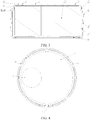
FIG. 1 is a structural diagram of a battery apparatus according to one embodiment of the present disclosure; -
FIG. 2 is a sectional view of a battery apparatus according to one embodiment of the present disclosure; -
FIG. 3 is a sectional view of a battery apparatus of a second type according to one embodiment of the present disclosure; -
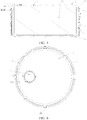
FIG. 4 is a top view of a battery apparatus of a second type according to one embodiment of the present disclosure; -
FIG. 5 is a sectional view of a battery apparatus of a third type according to one embodiment of the present disclosure; -
FIG. 6 is a top view of a battery apparatus of a third type according to one embodiment of the present disclosure; and -
FIGS. 7-10 are schematic views showing a pressure relief principle of a battery apparatus according to one embodiment of the present disclosure. - Description of reference numerals: 11: first tubular side wall; 12: top cap; 13: bottom cap; 14: explosion-proof groove; 15: pressure releasing hole; 16: sealing cap; 17: insulation loop; 18: notch; 19: tongue-shaped portion; 20: recessed structure; 21: partial crimped edge; 22: second tubular side wall; 23: battery cell; and 24: sealing structure.
- Various exemplary embodiments of the present invention will now be described in detail with reference to the accompanying drawings. It should be noted that the relative arrangement of the components and steps, numerical expressions, and numerical values set forth in these embodiments do not limit the scope of the present invention unless it is specifically stated otherwise.
- The following description of at least one exemplary embodiment is in fact merely illustrative and is in no way intended as a limitation to the present invention and its application or use.
- Techniques, methods, and devices known to those of ordinary skill in the relevant art may not be discussed in detail, but should be considered as part of the description where appropriate.
- Any specific value in all the examples shown and discussed herein shall be interpreted to be illustrative only, and shall not be interpreted as limitative. As such, other examples of exemplary embodiments may have different values.
- It should be noted that like reference numbers and letters are used to depict similar terms in the following figures, and therefore, once an item is defined in a figure, no further discussion on the item is needed in subsequent figures.
- According to one embodiment of the present disclosure, a battery apparatus is provided. As shown in
FIGS. 1 and 2 , the battery apparatus is a primary or secondary battery, and includes a first shell and a second shell that are fit together. Both the first shell and the second shell are made of a metal material, such as aluminum alloy, stainless steel or the like. The first shell and the second shell function as two electrodes of the battery apparatus, respectively. - As shown in
FIGS. 1-3 , the first shell includes a firsttubular side wall 11 and atop cap 12 arranged at one end of the firsttubular side wall 11. The one end of the firsttubular side wall 11 which faces thetop cap 12 is an open end. The second shell includes a secondtubular side wall 22 and abottom cap 13 arranged at one end of the secondtubular side wall 22. The one end of the secondtubular side wall 22 which faces thebottom cap 13 is an open end. - As shown in
FIGS. 2 ,3 and5 , arecessed structure 20 is formed in at least part of a connection region between the secondtubular side wall 22 and thebottom cap 13. The connection region is located near a corner. Of course, for easy arrangement, the connection region may have a set distance from the corner, but can also be directly formed in the corner. The recessedstructure 20 is a loop-shaped groove or a discontinuous groove, arranged around thebottom cap 13. - The first shell and the second shell are plugged together in such a way that their respective open ends are opposite to each other. The first
tubular side wall 11 sleeves the secondtubular side wall 22. An insulation sealing piece is arranged between the firsttubular side wall 11 and the secondtubular side wall 22. An inner diameter of the firsttubular side wall 11, e.g., is greater than an outer diameter of the secondtubular side wall 22. The insulation sealing piece is aninsulation loop 17 made of a plastic or rubber material, which material features excellent insulation and sealing effect. - For example, as shown in
FIG. 7 , theinsulation loop 17 forms a U-shaped portion at a position where a sealingstructure 24 locates. The U-shaped portion wraps the open end of the second shell. The U-shaped portion features larger contact area between its (inner and outer) surfaces and the two shells, respectively, thereby significantly improving the sealing effect of the sealing structure. The sealingstructure 24 refers to a sealing structure formed between the open end of the second shell and thetop cap 12 of the first shell. - Before assembly, at first, a
battery cell 23 is placed in the second shell, and theinsulation loop 17 sleeves the secondtubular side wall 22. Thebattery cell 23 may be, but is not limited to, a lithiumion battery cell 23, a lithiummetal battery cell 23, etc. Then, open ends of the two shells are opposite to each other, and the secondtubular side wall 22 is plugged into the firsttubular side wall 11. A hermetic cavity is formed inside the first shell and the second shell. The firsttubular side wall 11 is extruded towards the secondtubular side wall 22 so as to achieve better sealing. - As shown in
FIGS. 3, 4 and6-10 , a portion of the firsttubular side wall 11 close to its open end is bent towards the recessedstructure 20 along part of a circumference of the open end, so as to form a partial crimpededge 21. The partial crimpededge 21 is clamped to the recessedstructure 20. The partial crimped edge tends to deform when partially pressurized, and the first shell partially deforms when internal pressure of the battery apparatus reaches a set value, so that the sealing structure between the first shell and the second shell is broken, thereby releasing pressure. - For example, the first shell partially deforms along a radial direction. The radial direction is indicated by an arrow in
FIG. 10 . For example, when pressure in the cavity reaches 2MPa, the partial crimpededge 21 moves away from the recessedstructure 20 along the radial direction, and is finally detached from the recessed structure, so that the sealingstructure 24 between the first shell and the second shell is broken, thereby releasing pressure. - As shown in
FIG. 9 , when the pressure in the cavity reaches 2MPa, the secondtubular side wall 22 maintains its original shape. Since the partial crimpededge 21 is detached from the recessedstructure 20, the open end of the firsttubular side wall 11 deforms. Deforming of the open end of the firsttubular side wall 11 causes deforming of a portion close to thetop cap 12, thereby breaking the sealingstructure 24 and forming a break. Gas inside escapes from the break. - For example, as shown in
FIGS. 9 and 10 , the first shell deforms due to internal pressure, and its cross section changes from a circular one to a spindle shape, an elliptical shape or the like. The two partialcrimped edges 21 move away from each other and are finally detached from the recessedstructure 20, while breaking the sealing structure at the bottom of the first shell. - Of course, the number of the partial crimped
edges 21 is not limited to 2 or 3, and may be set by those skilled in the art according to actual needs. - In this example, the partial crimped
edge 21 is arranged at a portion of the first tubular side wall close to its open end along part of a circumference of the open end. This arrangement provides a structure that is relatively unstable, as compared with an arrangement that a crimped edge is formed along the whole circumference of the open end. When an internal pressure of the battery apparatus is increased to the set value, an extruded region of the crimped edge preferentially deforms, and therefore, the first shell and the second shell may deform punctually under a small pressure without a large axial displacement while ensuring sealing performance of the battery apparatus, thereby breaking the sealing structure and relieving the pressure. As such, safety performance of the battery is made more excellent. - In addition, since the battery apparatus releases pressure through the deformation of the first shell, the two shells are not largely separated and less damage would occur to the outside.
- In addition, the
partial roller edge 21 is separated from the recessedstructure 20 at least along the radial direction, and accordingly, separation in this way can release pressure more quickly with less accumulated energy, improving safety. - In one example, as shown in
FIGS. 1 ,4 and6 , there is a plurality of (such as 3) partial crimped edges 21. For example, the plurality of partial crimpededges 21 is distributed with respect to the open end of the first shell. In this example, the plurality of partial crimpededges 21 enables the first shell and the second shell to have the same explosive-proof grade at all positions, thus ensuring better reliability and stability of the battery apparatus. - For example, the partial crimped
edges 21 are uniformly distributed with respect to the open end of the first shell. As such, the first shell and the second shell are fixed more uniformly along the circumference of the open end, with higher explosive-proof grade. - Of course, the plurality of partial crimped
edges 21 may also be non-uniformly distributed with respect to the open end of the first shell. - In other examples, there may also be provided only one partial crimped
edge 21. This arrangement also features excellent pressure-relief and explosion-proof effect. Sealing between the first and the second shell is achieved by tight press-fit between the firsttubular side wall 11, theinsulation loop 17, and the secondtubular side wall 22. - There is a plurality of arrangements for the partial crimped
edge 21. In one example, as shown inFIG. 1 , a plurality ofnotches 18 is formed into a portion of the firsttubular side wall 11 close to its open end. Thenotches 18 may be formed through e.g., laser etching, plasma cutting, punching or the like. A tongue-shapedportion 19 is formed betweenadjacent notches 18. A left side and a right side of the tongue-shapedportion 19 are separated from other portions of the firsttubular side wall 11. The tongue-shapedportion 19 is bent towards the recessedstructure 20 so as to form the partial crimpededge 21. For example, the tongue-shapedportion 19 is extruded towards the recessedstructure 20 by punching, so that the tongue-shaped 19 is fitted onto the recessedstructure 20 and thus clamped to the recessedstructure 20. - The tongue-shaped
portion 19 is in point contact with the recessedstructure 20. Alternatively, the tongue-shapedportion 19 has an arc, and is in arc surface contact with the recessedstructure 20. - In this example, the tongue-shaped
portion 19 is more firmly clamped to the recessedstructure 20. The sealing effect between the first shell and the second shell is better. - In addition, bending of the tongue-shaped
portion 19 does not affect other portions of the firsttubular side wall 11. Therefore, the overall structure of the battery apparatus is kept. - In another example, the portion of the first
tubular side wall 11 close to its open end is bent towards the recessedstructure 20 to form the partial crimpededges 21, and there is no need for thenotches 18. - The shell may be made of metal, for example. The portion of the open end of the first shell is partially punched inwards by punching or rolling, so as to form the partial crimped edges 21. As such, clamping may also be formed.
- In one example, as shown in
FIGS. 1 and 2 , an explosion-proof groove 14 is formed in thebottom cap 13 and/or thetop cap 12. When pressure in the battery apparatus reaches a set value, the explosion-proof groove 14 is broken, thereby releasing pressure. A cross section of the explosion-proof groove 14 may be e.g., U-shaped, V-shaped or the like. The explosion-proof groove 14 is formed through laser etching or chemical etching. The explosion-proof groove 14 is formed on an inner or outer surface of thetop cap 12 and/or thebottom cap 13. The abovementioned shape results in stress concentration at the bottom of the explosion-proof groove 14, and the explosion-proof groove 14 is easily broken with highly sensitivity. - The explosion-
proof groove 14 may have e.g., a loop shape or a line shape. The loop shape may include e.g., a rectangular loop shape, a circular loop shape, an elliptical loop shape, and the like. The loop-shaped explosion-proof groove 14 is more easily broken and forms a through hole after being broken. Comparing with a cleft, a through hole releases pressure more quickly and features better explosion-proof performance. The line shape may include e.g., a rectilinear line, an arc, a wavy line, and the like. All of the above shapes have good pressure relief and explosion-proof effects. - In one example, the explosion-
proof groove 14 takes the shape of a positive sign or a negative sign. Thetop cap 12, for example, generally functions as a positive electrode of the battery apparatus. A positive electrode collector of thebattery cell 23 is electrically connected with thetop cap 12. A"+" shaped explosion-proof groove 14 is formed in the outer surface of the top cap 12(e.g., in the central portion of the top cap 12). Thebottom cap 13 is usually used as a negative electrode of the battery apparatus. A negative electrode collector of thebattery cell 23 is electrically connected with thebottom cap 13. A "-" shaped explosion-proof groove 14 is formed in the outer surface of the bottom cap 13(e.g., in the central portion of the bottom cap 13). In this example, the explosion-proof groove 14 functions not only to release the pressure and prevent explosion, but also to identify the positive electrode and the negative electrode. - In some battery apparatuses, in order to ensure structural strength, the first shell and the second shell are thick, and do not deform easily. An explosion-
proof groove 14 formed in this way has low sensitivity, and cannot release pressure under relatively low pressure (for example, 2MPa). - In order to solve this technical problem, in one example, as shown in
FIGS. 3-6 , apressure releasing hole 15 is formed in thebottom cap 13 and/or thetop cap 12. Thepressure releasing hole 15 is used for enabling gas in the battery apparatus to flow out so as to release pressure. Normally, thepressure releasing hole 15 is sealed. For example, a sealingcap 16 is arranged on thepressure releasing hole 15. The sealingcap 16 has a structural strength lower than a structural strength of thetop cap 12 or thebottom cap 13 where the sealingcap 16 is located. In this example, since the structural strength of the sealingcap 16 is relatively low, the sealing cap can be broken under the relatively low pressure so as to release pressure. - Further, as shown in
FIGS. 3 ,5 and 6 , an explosion-proof groove 14 is formed in the sealingcap 16. The shape of the explosion-proof 14 is as described above. - In this example, since the structural strength of the sealing
cap 16 is lower than the structural strength of thetop cap 12 or thebottom cap 13 where the sealingcap 16 is located, the explosion-proof 14 may be broken under relatively low pressure. By this means, the explosion-proof groove 14 has higher sensitivity. - For example, the sealing
cap 16 is made of a metal, such as copper alloy, aluminum alloy, stainless steel, etc. The sealing cap is arranged on thepressure releasing hole 15 by laser welding or resistance welding to form sealing. - The material of the sealing
cap 16 is for example the same as that of thetop cap 12 or thebottom cap 13 where the sealingcap 16 is located. The thickness of the sealingcap 16 is smaller than the thickness of thetop cap 12 or thebottom cap 13 where the sealingcap 16 is located. Alternatively, the sealingcap 16 may be made of metal with a lower structural strength. For example, thetop cap 12 or thebottom cap 13 is made of stainless steel, while the sealingcap 16 is made of copper, aluminum or the like. - In one example, the explosion-proof groove has a depth equal to 30%-90% of the thickness of a cap in which the explosion-proof groove is formed. The cap includes the
top cap 12, thebottom cap 13 or the sealingcap 16. In this depth range, the battery apparatus has excellent sealing performance and safety performance. - In the above embodiment, the clamping of the partial crimped
edge 21 and the recessedstructure 20, as well as the sealingcap 16 and the explosion-proof groove 14, together form a multilevel safety measure. As such, when the pressure in the battery apparatus reaches the set value, at least one level of the safety measure can function to release the pressure. With such an arrangement, safety performance of the battery apparatus is significantly improved. - According to another embodiment of the present disclosure, an electronic device is provided. The electronic device may be, but is not limited to a mobile phone, a tablet computer, a smart watch, a laptop computer, a game machine, an interphone, a headphone, an e-book reader, or the like.
- The electronic device includes a housing in addition to the battery apparatus mentioned above. A PCB is arranged in the housing. The battery apparatus is arranged in the housing and is electrically connected with a power utilization device in the electronic device through the PCB.
- The electronic device is characterized in excellent safety performance.
- While some specific embodiments of the present invention have been illustrated by way of example, it will be understood by those skilled in the art that the foregoing examples are provided for the purpose of illustration and are not intended to limit the scope of the present invention. It will be understood by those skilled in the art that the foregoing embodiments may be modified without departing from the scope and spirit of the present invention. The scope of the present invention is subject to the attached claims.
Claims (10)
- A battery apparatus, comprising:a first shell, including a first tubular side wall and a top cap arranged at one end of the first tubular side wall; anda second shell, including a second tubular side wall and a bottom cap arranged at one end of the second tubular side wall, a recessed structure is formed in at least part of a connection region between the second tubular side wall and the bottom cap;the first shell and the second shell are plugged together in such a way that their respective open ends are opposite to each other, the first tubular side wall sleeves the second tubular side wall;an insulation sealing piece is arranged between the first tubular side wall and the second tubular side wall;a portion of the first tubular side wall close to its open end is bent towards the recessed structure along part of a circumference of the open end to form a partial crimped edge, the partial crimped edge is clamped to the recessed structure; andwhen internal pressure of the battery apparatus reaches a set value, the first shell partially deforms, so that a sealing structure between the first shell and the second shell is broken, thereby releasing pressure.
- The battery apparatus according to claim 1, wherein an explosion-proof groove is formed in the bottom cap and/or the top cap.
- The battery apparatus according to claim 1 or 2, wherein a pressure releasing hole is formed in the bottom cap and/or the top cap; a sealing cap is arranged on the pressure releasing hole; and the sealing cap has a structural strength lower than a structural strength of the top cap or the bottom cap where the sealing cap is located.
- The battery apparatus according to any one of claims 1-3, wherein an explosion-proof groove is formed in the sealing cap.
- The battery apparatus according to any one of claims 1-4, wherein the explosion-proof groove has a depth equal to 30%-90% of the thickness of a cap in which the explosion-proof groove is formed.
- The battery apparatus according to any one of claims 1-5, wherein the explosion-proof groove has a loop shape or a line shape.
- The battery apparatus according to any one of claims 1-6, wherein a portion of the first tubular side wall close to its open end is bent towards the recessed structure so as to form the partial crimped edge.
- The battery apparatus according to any one of claims 1-7, wherein there are one or more partial crimped edges.
- The battery apparatus according to any one of claims 1-4 and 8, wherein a plurality of notches is formed in a portion of the first tubular side wall close to its open end; a tongue-shaped portion is formed between adjacent notches; and the tongue-shaped portion is bent towards the recessed structure so as to form the partial crimped edge.
- An electronic device, comprising the battery apparatus according to any one of claims 1-9.
Applications Claiming Priority (3)
| Application Number | Priority Date | Filing Date | Title |
|---|---|---|---|
| CN201910107887.7A CN109786611B (en) | 2019-02-02 | 2019-02-02 | Battery devices and electronic equipment |
| CN201920187952.7U CN209526141U (en) | 2019-02-02 | 2019-02-02 | Battery devices and electronic equipment |
| PCT/CN2019/095497 WO2020155563A1 (en) | 2019-02-02 | 2019-07-10 | Battery device and electronic device |
Publications (2)
| Publication Number | Publication Date |
|---|---|
| EP3780144A1 true EP3780144A1 (en) | 2021-02-17 |
| EP3780144A4 EP3780144A4 (en) | 2022-02-02 |
Family
ID=71841148
Family Applications (1)
| Application Number | Title | Priority Date | Filing Date |
|---|---|---|---|
| EP19913570.8A Pending EP3780144A4 (en) | 2019-02-02 | 2019-07-10 | Battery device and electronic device |
Country Status (3)
| Country | Link |
|---|---|
| US (1) | US11757154B2 (en) |
| EP (1) | EP3780144A4 (en) |
| WO (1) | WO2020155563A1 (en) |
Families Citing this family (3)
| Publication number | Priority date | Publication date | Assignee | Title |
|---|---|---|---|---|
| CN114024087B (en) * | 2021-09-26 | 2022-10-18 | 常州瑞德丰精密技术有限公司 | Rupture disk for double-open type blasting |
| CN217387320U (en) * | 2022-04-20 | 2022-09-06 | 比亚迪股份有限公司 | A battery case, battery and electronic equipment |
| CN115312961A (en) * | 2022-08-22 | 2022-11-08 | 苏州湖林电子部件有限公司 | Explosion-proof battery shell and processing method thereof |
Family Cites Families (11)
| Publication number | Priority date | Publication date | Assignee | Title |
|---|---|---|---|---|
| TW504854B (en) * | 1999-08-27 | 2002-10-01 | Toshiba Battery | Flat non-aqueous electrolyte secondary cell |
| DE102005058132A1 (en) * | 2005-11-30 | 2007-06-06 | Varta Microbattery Gmbh | Galvanic element with new housing |
| EP2071646A4 (en) * | 2006-09-29 | 2010-10-27 | Shenzhen Bak Battery Co Ltd | BOX FOR BATTERY HEART AND BATTERY |
| WO2010089152A1 (en) * | 2009-02-09 | 2010-08-12 | Varta Microbattery Gmbh | Button cells and method for producing same |
| KR101093401B1 (en) * | 2009-11-18 | 2011-12-14 | 삼성에스디아이 주식회사 | Cap up plate and cylindrical secondary battery having same |
| DE102010042548A1 (en) * | 2010-10-16 | 2012-04-19 | Varta Microbattery Gmbh | Button cell with burst protection |
| EP2652815A1 (en) | 2010-12-17 | 2013-10-23 | Advanced Bionics AG | Sound processor housings, sound processors and implantable cochlear stimulation systems including the same |
| CN107425145B (en) * | 2017-06-20 | 2023-06-20 | 惠州亿纬锂能股份有限公司 | Button type lithium battery core sealing structure and sealing method |
| CN109004261B (en) * | 2018-07-05 | 2024-07-30 | 广东微电新能源有限公司 | A battery |
| CN109216596A (en) * | 2018-08-09 | 2019-01-15 | 广东微电新能源有限公司 | A kind of battery |
| CN109786611B (en) * | 2019-02-02 | 2024-01-16 | 广东微电新能源有限公司 | Battery devices and electronic equipment |
-
2019
- 2019-07-10 US US16/973,569 patent/US11757154B2/en active Active
- 2019-07-10 EP EP19913570.8A patent/EP3780144A4/en active Pending
- 2019-07-10 WO PCT/CN2019/095497 patent/WO2020155563A1/en not_active Ceased
Also Published As
| Publication number | Publication date |
|---|---|
| EP3780144A4 (en) | 2022-02-02 |
| US20210249732A1 (en) | 2021-08-12 |
| US11757154B2 (en) | 2023-09-12 |
| WO2020155563A1 (en) | 2020-08-06 |
Similar Documents
| Publication | Publication Date | Title |
|---|---|---|
| CN109786611B (en) | Battery devices and electronic equipment | |
| TWI725613B (en) | Explosion-proof enclosure for an energy storage device and an energy storage device | |
| JP5399990B2 (en) | Secondary battery | |
| CN209526141U (en) | Battery devices and electronic equipment | |
| KR102249892B1 (en) | Rechargeable battery | |
| EP3951907A1 (en) | Cylindrical battery gasket for preventing corrosion of battery case, and cylindrical battery comprising same | |
| KR102007702B1 (en) | Rechargeable battery | |
| US9853266B2 (en) | Vent and cap assembly of power battery | |
| EP3614451B1 (en) | Secondary battery | |
| JP7493010B6 (en) | Battery canister | |
| US11742542B2 (en) | Explosion-proof enclosure for energy storage device and energy storage device | |
| US11757154B2 (en) | Battery apparatus and electronic device | |
| CN110459703B (en) | Battery device and electronic equipment | |
| EP2908359B1 (en) | Secondary battery | |
| EP4510321A1 (en) | Explosion-proof battery | |
| EP4080658B1 (en) | Safety apparatus and battery | |
| US12237518B2 (en) | Cylindrical battery | |
| JP2022191525A6 (en) | Battery canister | |
| CN111682130A (en) | button battery | |
| CN112886111B (en) | Lithium battery sealing structure | |
| CN210743987U (en) | Battery device and electronic equipment | |
| KR20160049151A (en) | Rechargeable battery | |
| US20160043367A1 (en) | Rechargeable battery | |
| CN210403874U (en) | Lithium ion battery structure | |
| KR102461773B1 (en) | Secondary battery and manufacture method for the same |
Legal Events
| Date | Code | Title | Description |
|---|---|---|---|
| STAA | Information on the status of an ep patent application or granted ep patent |
Free format text: STATUS: THE INTERNATIONAL PUBLICATION HAS BEEN MADE |
|
| PUAI | Public reference made under article 153(3) epc to a published international application that has entered the european phase |
Free format text: ORIGINAL CODE: 0009012 |
|
| STAA | Information on the status of an ep patent application or granted ep patent |
Free format text: STATUS: REQUEST FOR EXAMINATION WAS MADE |
|
| 17P | Request for examination filed |
Effective date: 20201029 |
|
| AK | Designated contracting states |
Kind code of ref document: A1 Designated state(s): AL AT BE BG CH CY CZ DE DK EE ES FI FR GB GR HR HU IE IS IT LI LT LU LV MC MK MT NL NO PL PT RO RS SE SI SK SM TR |
|
| AX | Request for extension of the european patent |
Extension state: BA ME |
|
| REG | Reference to a national code |
Ref country code: DE Ref legal event code: R079 Free format text: PREVIOUS MAIN CLASS: H01M0002100000 Ipc: H01M0050107000 |
|
| A4 | Supplementary search report drawn up and despatched |
Effective date: 20220107 |
|
| RIC1 | Information provided on ipc code assigned before grant |
Ipc: H01M 50/367 20210101ALI20211227BHEP Ipc: H01M 50/342 20210101ALI20211227BHEP Ipc: H01M 50/202 20210101ALI20211227BHEP Ipc: H01M 50/107 20210101AFI20211227BHEP |
|
| DAV | Request for validation of the european patent (deleted) | ||
| DAX | Request for extension of the european patent (deleted) |