EP3780135A1 - Battery - Google Patents
Battery Download PDFInfo
- Publication number
- EP3780135A1 EP3780135A1 EP19780530.2A EP19780530A EP3780135A1 EP 3780135 A1 EP3780135 A1 EP 3780135A1 EP 19780530 A EP19780530 A EP 19780530A EP 3780135 A1 EP3780135 A1 EP 3780135A1
- Authority
- EP
- European Patent Office
- Prior art keywords
- battery
- gasket
- open rim
- sealing plate
- cylindrical portion
- Prior art date
- Legal status (The legal status is an assumption and is not a legal conclusion. Google has not performed a legal analysis and makes no representation as to the accuracy of the status listed.)
- Withdrawn
Links
- 238000007789 sealing Methods 0.000 claims abstract description 90
- 230000002093 peripheral effect Effects 0.000 claims abstract description 38
- WABPQHHGFIMREM-UHFFFAOYSA-N lead(0) Chemical compound [Pb] WABPQHHGFIMREM-UHFFFAOYSA-N 0.000 description 6
- 239000000463 material Substances 0.000 description 6
- 229910052751 metal Inorganic materials 0.000 description 6
- 239000002184 metal Substances 0.000 description 6
- 239000007773 negative electrode material Substances 0.000 description 6
- -1 polypropylene Polymers 0.000 description 6
- 238000003825 pressing Methods 0.000 description 6
- 239000011888 foil Substances 0.000 description 5
- 238000000465 moulding Methods 0.000 description 5
- 239000007774 positive electrode material Substances 0.000 description 5
- 239000011149 active material Substances 0.000 description 4
- 239000011230 binding agent Substances 0.000 description 4
- 239000004020 conductor Substances 0.000 description 4
- 239000011347 resin Substances 0.000 description 4
- 229920005989 resin Polymers 0.000 description 4
- 239000004952 Polyamide Substances 0.000 description 3
- 238000004519 manufacturing process Methods 0.000 description 3
- 238000000034 method Methods 0.000 description 3
- 229920002647 polyamide Polymers 0.000 description 3
- 238000003466 welding Methods 0.000 description 3
- YEJRWHAVMIAJKC-UHFFFAOYSA-N 4-Butyrolactone Chemical compound O=C1CCCO1 YEJRWHAVMIAJKC-UHFFFAOYSA-N 0.000 description 2
- OKTJSMMVPCPJKN-UHFFFAOYSA-N Carbon Chemical compound [C] OKTJSMMVPCPJKN-UHFFFAOYSA-N 0.000 description 2
- WHXSMMKQMYFTQS-UHFFFAOYSA-N Lithium Chemical compound [Li] WHXSMMKQMYFTQS-UHFFFAOYSA-N 0.000 description 2
- HBBGRARXTFLTSG-UHFFFAOYSA-N Lithium ion Chemical compound [Li+] HBBGRARXTFLTSG-UHFFFAOYSA-N 0.000 description 2
- PXHVJJICTQNCMI-UHFFFAOYSA-N Nickel Chemical compound [Ni] PXHVJJICTQNCMI-UHFFFAOYSA-N 0.000 description 2
- 239000004813 Perfluoroalkoxy alkane Substances 0.000 description 2
- 239000004698 Polyethylene Substances 0.000 description 2
- 239000004734 Polyphenylene sulfide Substances 0.000 description 2
- 239000004743 Polypropylene Substances 0.000 description 2
- RTAQQCXQSZGOHL-UHFFFAOYSA-N Titanium Chemical compound [Ti] RTAQQCXQSZGOHL-UHFFFAOYSA-N 0.000 description 2
- 229910045601 alloy Inorganic materials 0.000 description 2
- 239000000956 alloy Substances 0.000 description 2
- 230000004075 alteration Effects 0.000 description 2
- 239000003125 aqueous solvent Substances 0.000 description 2
- 238000002788 crimping Methods 0.000 description 2
- 239000003792 electrolyte Substances 0.000 description 2
- 150000002148 esters Chemical class 0.000 description 2
- GAEKPEKOJKCEMS-UHFFFAOYSA-N gamma-valerolactone Chemical compound CC1CCC(=O)O1 GAEKPEKOJKCEMS-UHFFFAOYSA-N 0.000 description 2
- 229910002804 graphite Inorganic materials 0.000 description 2
- 239000010439 graphite Substances 0.000 description 2
- 229910052744 lithium Inorganic materials 0.000 description 2
- 229910001416 lithium ion Inorganic materials 0.000 description 2
- 229910003002 lithium salt Inorganic materials 0.000 description 2
- 159000000002 lithium salts Chemical class 0.000 description 2
- 238000012986 modification Methods 0.000 description 2
- 230000004048 modification Effects 0.000 description 2
- 229920011301 perfluoro alkoxyl alkane Polymers 0.000 description 2
- 229920001707 polybutylene terephthalate Polymers 0.000 description 2
- 229920000573 polyethylene Polymers 0.000 description 2
- 229920000069 polyphenylene sulfide Polymers 0.000 description 2
- 229920001155 polypropylene Polymers 0.000 description 2
- 229920001343 polytetrafluoroethylene Polymers 0.000 description 2
- 239000004810 polytetrafluoroethylene Substances 0.000 description 2
- 238000002360 preparation method Methods 0.000 description 2
- 230000001681 protective effect Effects 0.000 description 2
- 239000010935 stainless steel Substances 0.000 description 2
- 229910001220 stainless steel Inorganic materials 0.000 description 2
- ZZXUZKXVROWEIF-UHFFFAOYSA-N 1,2-butylene carbonate Chemical compound CCC1COC(=O)O1 ZZXUZKXVROWEIF-UHFFFAOYSA-N 0.000 description 1
- 229920000178 Acrylic resin Polymers 0.000 description 1
- 239000004925 Acrylic resin Substances 0.000 description 1
- 229910000838 Al alloy Inorganic materials 0.000 description 1
- RYGMFSIKBFXOCR-UHFFFAOYSA-N Copper Chemical compound [Cu] RYGMFSIKBFXOCR-UHFFFAOYSA-N 0.000 description 1
- OIFBSDVPJOWBCH-UHFFFAOYSA-N Diethyl carbonate Chemical compound CCOC(=O)OCC OIFBSDVPJOWBCH-UHFFFAOYSA-N 0.000 description 1
- KMTRUDSVKNLOMY-UHFFFAOYSA-N Ethylene carbonate Chemical compound O=C1OCCO1 KMTRUDSVKNLOMY-UHFFFAOYSA-N 0.000 description 1
- 229910000552 LiCF3SO3 Inorganic materials 0.000 description 1
- 229910032387 LiCoO2 Inorganic materials 0.000 description 1
- 229910003005 LiNiO2 Inorganic materials 0.000 description 1
- 229910001290 LiPF6 Inorganic materials 0.000 description 1
- 239000004962 Polyamide-imide Substances 0.000 description 1
- 229910000676 Si alloy Inorganic materials 0.000 description 1
- VYPSYNLAJGMNEJ-UHFFFAOYSA-N Silicium dioxide Chemical compound O=[Si]=O VYPSYNLAJGMNEJ-UHFFFAOYSA-N 0.000 description 1
- 229920000800 acrylic rubber Polymers 0.000 description 1
- 229910052782 aluminium Inorganic materials 0.000 description 1
- XAGFODPZIPBFFR-UHFFFAOYSA-N aluminium Chemical compound [Al] XAGFODPZIPBFFR-UHFFFAOYSA-N 0.000 description 1
- 239000006229 carbon black Substances 0.000 description 1
- 239000003575 carbonaceous material Substances 0.000 description 1
- 239000002131 composite material Substances 0.000 description 1
- 229910052802 copper Inorganic materials 0.000 description 1
- 239000010949 copper Substances 0.000 description 1
- 125000004122 cyclic group Chemical group 0.000 description 1
- 230000003247 decreasing effect Effects 0.000 description 1
- 230000008021 deposition Effects 0.000 description 1
- 238000010586 diagram Methods 0.000 description 1
- IEJIGPNLZYLLBP-UHFFFAOYSA-N dimethyl carbonate Chemical compound COC(=O)OC IEJIGPNLZYLLBP-UHFFFAOYSA-N 0.000 description 1
- 230000000694 effects Effects 0.000 description 1
- JBTWLSYIZRCDFO-UHFFFAOYSA-N ethyl methyl carbonate Chemical compound CCOC(=O)OC JBTWLSYIZRCDFO-UHFFFAOYSA-N 0.000 description 1
- 239000004744 fabric Substances 0.000 description 1
- NBVXSUQYWXRMNV-UHFFFAOYSA-N fluoromethane Chemical compound FC NBVXSUQYWXRMNV-UHFFFAOYSA-N 0.000 description 1
- 230000006872 improvement Effects 0.000 description 1
- 238000005304 joining Methods 0.000 description 1
- MHCFAGZWMAWTNR-UHFFFAOYSA-M lithium perchlorate Chemical compound [Li+].[O-]Cl(=O)(=O)=O MHCFAGZWMAWTNR-UHFFFAOYSA-M 0.000 description 1
- 229910001486 lithium perchlorate Inorganic materials 0.000 description 1
- 229910001496 lithium tetrafluoroborate Inorganic materials 0.000 description 1
- HSFDLPWPRRSVSM-UHFFFAOYSA-M lithium;2,2,2-trifluoroacetate Chemical compound [Li+].[O-]C(=O)C(F)(F)F HSFDLPWPRRSVSM-UHFFFAOYSA-M 0.000 description 1
- 229910044991 metal oxide Inorganic materials 0.000 description 1
- 150000004706 metal oxides Chemical class 0.000 description 1
- 229910052759 nickel Inorganic materials 0.000 description 1
- 239000011255 nonaqueous electrolyte Substances 0.000 description 1
- 230000008520 organization Effects 0.000 description 1
- 239000002245 particle Substances 0.000 description 1
- 229920000058 polyacrylate Polymers 0.000 description 1
- 229920002312 polyamide-imide Polymers 0.000 description 1
- 229920000098 polyolefin Polymers 0.000 description 1
- RUOJZAUFBMNUDX-UHFFFAOYSA-N propylene carbonate Chemical compound CC1COC(=O)O1 RUOJZAUFBMNUDX-UHFFFAOYSA-N 0.000 description 1
- 239000005060 rubber Substances 0.000 description 1
- 229910052814 silicon oxide Inorganic materials 0.000 description 1
- 238000009751 slip forming Methods 0.000 description 1
- 229910052719 titanium Inorganic materials 0.000 description 1
- 239000010936 titanium Substances 0.000 description 1
- 238000007740 vapor deposition Methods 0.000 description 1
- 238000004804 winding Methods 0.000 description 1
Images



Classifications
-
- H—ELECTRICITY
- H01—ELECTRIC ELEMENTS
- H01M—PROCESSES OR MEANS, e.g. BATTERIES, FOR THE DIRECT CONVERSION OF CHEMICAL ENERGY INTO ELECTRICAL ENERGY
- H01M50/00—Constructional details or processes of manufacture of the non-active parts of electrochemical cells other than fuel cells, e.g. hybrid cells
- H01M50/10—Primary casings; Jackets or wrappings
- H01M50/147—Lids or covers
- H01M50/166—Lids or covers characterised by the methods of assembling casings with lids
-
- H—ELECTRICITY
- H01—ELECTRIC ELEMENTS
- H01M—PROCESSES OR MEANS, e.g. BATTERIES, FOR THE DIRECT CONVERSION OF CHEMICAL ENERGY INTO ELECTRICAL ENERGY
- H01M50/00—Constructional details or processes of manufacture of the non-active parts of electrochemical cells other than fuel cells, e.g. hybrid cells
- H01M50/10—Primary casings; Jackets or wrappings
- H01M50/147—Lids or covers
- H01M50/148—Lids or covers characterised by their shape
- H01M50/152—Lids or covers characterised by their shape for cells having curved cross-section, e.g. round or elliptic
-
- H—ELECTRICITY
- H01—ELECTRIC ELEMENTS
- H01M—PROCESSES OR MEANS, e.g. BATTERIES, FOR THE DIRECT CONVERSION OF CHEMICAL ENERGY INTO ELECTRICAL ENERGY
- H01M10/00—Secondary cells; Manufacture thereof
- H01M10/04—Construction or manufacture in general
-
- H—ELECTRICITY
- H01—ELECTRIC ELEMENTS
- H01M—PROCESSES OR MEANS, e.g. BATTERIES, FOR THE DIRECT CONVERSION OF CHEMICAL ENERGY INTO ELECTRICAL ENERGY
- H01M50/00—Constructional details or processes of manufacture of the non-active parts of electrochemical cells other than fuel cells, e.g. hybrid cells
- H01M50/10—Primary casings; Jackets or wrappings
- H01M50/102—Primary casings; Jackets or wrappings characterised by their shape or physical structure
- H01M50/107—Primary casings; Jackets or wrappings characterised by their shape or physical structure having curved cross-section, e.g. round or elliptic
-
- H—ELECTRICITY
- H01—ELECTRIC ELEMENTS
- H01M—PROCESSES OR MEANS, e.g. BATTERIES, FOR THE DIRECT CONVERSION OF CHEMICAL ENERGY INTO ELECTRICAL ENERGY
- H01M50/00—Constructional details or processes of manufacture of the non-active parts of electrochemical cells other than fuel cells, e.g. hybrid cells
- H01M50/10—Primary casings; Jackets or wrappings
- H01M50/147—Lids or covers
-
- H—ELECTRICITY
- H01—ELECTRIC ELEMENTS
- H01M—PROCESSES OR MEANS, e.g. BATTERIES, FOR THE DIRECT CONVERSION OF CHEMICAL ENERGY INTO ELECTRICAL ENERGY
- H01M50/00—Constructional details or processes of manufacture of the non-active parts of electrochemical cells other than fuel cells, e.g. hybrid cells
- H01M50/10—Primary casings; Jackets or wrappings
- H01M50/183—Sealing members
- H01M50/184—Sealing members characterised by their shape or structure
-
- H—ELECTRICITY
- H01—ELECTRIC ELEMENTS
- H01M—PROCESSES OR MEANS, e.g. BATTERIES, FOR THE DIRECT CONVERSION OF CHEMICAL ENERGY INTO ELECTRICAL ENERGY
- H01M50/00—Constructional details or processes of manufacture of the non-active parts of electrochemical cells other than fuel cells, e.g. hybrid cells
- H01M50/10—Primary casings; Jackets or wrappings
- H01M50/183—Sealing members
- H01M50/186—Sealing members characterised by the disposition of the sealing members
-
- H—ELECTRICITY
- H01—ELECTRIC ELEMENTS
- H01M—PROCESSES OR MEANS, e.g. BATTERIES, FOR THE DIRECT CONVERSION OF CHEMICAL ENERGY INTO ELECTRICAL ENERGY
- H01M50/00—Constructional details or processes of manufacture of the non-active parts of electrochemical cells other than fuel cells, e.g. hybrid cells
- H01M50/10—Primary casings; Jackets or wrappings
- H01M50/183—Sealing members
- H01M50/19—Sealing members characterised by the material
- H01M50/193—Organic material
-
- Y—GENERAL TAGGING OF NEW TECHNOLOGICAL DEVELOPMENTS; GENERAL TAGGING OF CROSS-SECTIONAL TECHNOLOGIES SPANNING OVER SEVERAL SECTIONS OF THE IPC; TECHNICAL SUBJECTS COVERED BY FORMER USPC CROSS-REFERENCE ART COLLECTIONS [XRACs] AND DIGESTS
- Y02—TECHNOLOGIES OR APPLICATIONS FOR MITIGATION OR ADAPTATION AGAINST CLIMATE CHANGE
- Y02E—REDUCTION OF GREENHOUSE GAS [GHG] EMISSIONS, RELATED TO ENERGY GENERATION, TRANSMISSION OR DISTRIBUTION
- Y02E60/00—Enabling technologies; Technologies with a potential or indirect contribution to GHG emissions mitigation
- Y02E60/10—Energy storage using batteries
-
- Y—GENERAL TAGGING OF NEW TECHNOLOGICAL DEVELOPMENTS; GENERAL TAGGING OF CROSS-SECTIONAL TECHNOLOGIES SPANNING OVER SEVERAL SECTIONS OF THE IPC; TECHNICAL SUBJECTS COVERED BY FORMER USPC CROSS-REFERENCE ART COLLECTIONS [XRACs] AND DIGESTS
- Y02—TECHNOLOGIES OR APPLICATIONS FOR MITIGATION OR ADAPTATION AGAINST CLIMATE CHANGE
- Y02P—CLIMATE CHANGE MITIGATION TECHNOLOGIES IN THE PRODUCTION OR PROCESSING OF GOODS
- Y02P70/00—Climate change mitigation technologies in the production process for final industrial or consumer products
- Y02P70/50—Manufacturing or production processes characterised by the final manufactured product
Definitions
- the present invention relates to a battery including a battery can, an electrode body housed in the battery can, and a sealing body sealing the opening of the battery can.
- the battery can When sealing the opening of the battery can with a sealing body, typically, the battery can is constricted inward in the vicinity of the opening, so that an annular groove is formed therearound.
- the sealing body has a gasket provided at its peripheral portion. The gasket of the sealing body is disposed between the end of the battery can and the annular groove, and compressed vertically, and thereby the sealing body is fixed to the battery can (see Patent Literature 1).
- the annular groove is formed close to the upper end surface of the electrode body housed in the battery can. Therefore, in order to prevent internal short circuit, an electrically insulating plate is necessary to be provided.
- the insulating plate is placed between the upper end surface of the electrode body and the annular groove.
- the annular groove whose thickness is more than twice as large as the wall thickness of the battery can, and the insulating plate. Accordingly, the shortest distance between the sealing body and the electrode body increases, and this imposes a limitation on the improvement in the energy density within the can.
- a battery including: a battery can having a cylindrical portion, a bottom wall closing one end of the cylindrical portion, and an open rim continuing to the other end of the cylindrical portion; an electrode body housed in the cylindrical portion; and a sealing body fixed to the open rim so as to seal an opening defined by the open rim, the sealing body including a sealing plate and a gasket disposed at a peripheral portion of the sealing plate, the gasket being compressed between an end surface of the peripheral portion and the open rim, in a radial direction of the opening.
- a battery according to the present embodiment includes: a battery can having a cylindrical portion, a bottom wall closing one end of the cylindrical portion, and an open rim continuing to the other end of the cylindrical portion; an electrode body housed in the cylindrical portion; and a sealing body fixed to the open rim so as to seal an opening defined by the open rim.
- the sealing body includes a sealing plate and a gasket disposed at a peripheral portion of the sealing plate.
- the gasket is compressed between an end surface of the peripheral portion of the sealing plate and the open rim, in the radial direction of the opening.
- the open rim has a pressing portion for pressing the gasket against the end surface of the peripheral portion of the sealing plate.
- the gasket is compressed by the pressing portion in the radial direction of the opening, and the repulsive force of the gasket acts to ensure the airtightness between the sealing body and the open rim.
- the open rim of the battery can presses the gasket not in the axial direction (hereinafter, sometimes referred to as Z direction) of the battery can but in the direction perpendicular to the Z direction (hereinafter, sometimes referred to as XY direction).
- Z direction the axial direction
- XY direction the direction perpendicular to the Z direction
- the scalar quantity of the vector in the XY direction is larger than that in the Z direction.
- the open rim of the battery can have a projection as at least part of the pressing portion, the projection protruding inward in the radial direction.
- the gasket is compressed in the radial direction at least by the projection.
- a projection can be formed by constricting the open rim inward.
- the projection may be formed intermittently in a plurality of numbers along the circumferential direction of the opening, or may be formed continuously along the circumferential direction of the opening.
- the continuously formed projection can form an annular groove along the circumferential direction of the opening.
- the projection(s) can press the gasket more strongly toward the end surface of the peripheral portion of the sealing plate. In this way, the airtightness between the sealing body and the open rim can be more reliably ensured.
- the gasket may be of any shape, and has: for example, an inner ring portion disposed on the side facing the electrode body (the inner side) of the peripheral portion of the sealing plate; and a side wall portion covering the end surface of the peripheral portion of the sealing plate. In this case, the side wall portion is compressed in the radial direction.
- the gasket preferably further has an outer ring portion disposed on the outer side of the peripheral portion of the sealing plate. More specifically, the gasket preferably has an outer ring portion and an inner ring portion sandwiching the peripheral portion of the sealing plate therebetween, and a side wall portion covering the end surface of the peripheral portion of the sealing plate so as to connect the outer ring portion with the inner ring portion.
- the projections are provided preferably at equi-angular intervals with respect to the center of the opening.
- the projection is preferably substantially equal in position to the center of the end surface of the peripheral portion of the sealing plate.
- the projection is substantially equal in position to the center of the end surface of the peripheral portion of the sealing plate means that, in the height direction of the battery can, the difference between the position of the projection and the center position of the end surface of the sealing plate is 2% or less of a height H of the battery can.
- a recessed groove may be formed so as to correspond to the projection provided on the open rim of the battery can.
- the open rim may be made smaller in outer diameter at the lowermost position (the innermost position) in contact with the gasket or its inner ring portion, than the cylindrical portion.
- the cap serves to protect the peripheral portion of the sealing plate and the open rim of the battery can.
- the cap may be designed in such a thickness that the outer diameter of the cap becomes substantially equal to the outer diameter of the cylindrical portion.
- the sealing plate and the gasket are integrally molded by an insert molding technique or the like. According to the integral molding, the sealing plate and the gasket are easily welded to each other. By integrally molding the sealing plate and the gasket, the sealing body can be handled as one component, which can simplify the production of the battery.
- the shortest distance between the sealing body and the electrode body can be decreased, and the energy density inside the can tends to be increased.
- the shortest distance between the sealing body and the electrode body can be set to, for example, 2 mm or less, and preferably 1.5 mm or less.
- FIG. 1A is a schematic vertical cross-sectional view of an essential part of a battery 10 according to the present embodiment.
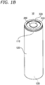
- FIG. 1B is an oblique view of the battery.
- the battery 10 has a cylindrical shape, and includes a cylindrical bottomed battery can 100, a cylindrical electrode body 200 housed in the can, and a sealing body 300 sealing the opening of the battery can 100.
- the battery can 100 includes: a cylindrical portion 120 housing the electrode body 200; a bottom wall 130 closing one end of the cylindrical portion 120; and an open rim 110 continuing to the other end of the cylindrical portion 120.
- the opening defined by the open rim 110 is closed by the sealing body 300.
- the sealing body 300 has a sealing plate 310 and a gasket 320 disposed at a peripheral portion 311 of the sealing plate 310.
- the sealing plate 310 is disk-shaped and has an explosion-proof function.
- the sealing plate 310 includes the peripheral portion 311 and a center region 312, both having a thick wall thickness and serving to provide structural strength, and a thin-walled portion 313 configured to exhibit an explosion-proof function.
- the thin-walled portion 313 is provided between the peripheral portion 311 and the center region 312.
- the sealing plate 310 functions as a terminal of one of the electrodes.
- the sealing plate 310 bulges outward, and the stress due to tension is concentrated, for example, on the boundary between the peripheral portion 311 and the thin-walled portion 313, causing a break to occur from the boundary. As a result, the internal pressure of the battery can 100 is released, and the safety of the battery 10 can be ensured. Alternatively, the sealing body 300 comes off from the open rim 110 and the internal pressure is released.
- the sealing plate 310 may be of any shape.
- the peripheral portion 311 is made thicker than the center region 312.
- the thick peripheral portion 311 can receive over a large area the pressure applied thereto from the open rim 110 of the battery can 100 in the radial direction of the opening, allowing the stress to be easily dispersed.
- a recessed groove 3111 is formed at the center position of an end surface 311T of the peripheral portion 311 so as to correspond to a projection 111 of the open rim 110.
- the gasket 320 has an outer ring portion 321 and an inner ring portion 322, and a side wall portion 323 connecting the outer ring portion 321 with the inner ring portion 322.
- the end surface 311T of the peripheral portion 311 of the sealing plate 310 is covered with the side wall portion 323.
- the outer ring portion 321 and the inner ring portion 322 sandwich the peripheral portion 311 of the sealing plate 310 therebetween, and thereby the gasket 320 is secured to the sealing plate 310.
- the outer ring portion 321, the inner ring portion 322, and the side wall portion 323 are formed as an integrally molded product.
- the gasket 320 can be integrally molded with the sealing plate 310, for example, by an insert molding technique.
- the open rim 110 of the battery can 100 and the sealing body 300 it is necessary that at least part of the open rim 110 presses the side wall portion 323 of the gasket 320 against the end surface 311T of the peripheral portion 311 of the sealing plate 310, so as to compress the side wall portion 323 in the radial direction of the opening.
- the projection 111 protruding inward is formed on the open rim 110 along the circumference of the opening, and the projection 111 is pressing the side wall portion 323 against the end surface 311T.
- the side wall portion 323 of the gasket 320 may be provided with a recessed portion 3231 in advance at a position corresponding to the projection 111. Providing the recessed portion 3231 on the gasket 320 can prevent the gasket 320 from being excessively deformed when the side wall 323 is compressed.
- the projection 111 is substantially equal in position to the center of the end surface 311T of the peripheral portion 311 of the sealing plate 310.
- the endmost portion having the end surface 110T extends in the direction forming an angle of less than 5° with the axial direction (Z direction) of the battery can 100. This prevents the gasket 320 from being subjected to excessive stress, making it possible for the gasket 320 to ensure the airtightness more easily and reliably.
- the open rim 110 of the battery can 100 is made smaller in outer diameter at the lowest position in contact with the inner ring portion 322 of the gasket 320, than the cylindrical portion 120, in the height direction of the battery can 100 of the battery 10.
- the outer ring portion 321 protrudes beyond the end surface 110T of the open rim 110 in the axial direction (Z direction) of the battery can 100.
- FIG. 2A is a schematic vertical cross-sectional view of an essential part of the battery 10 including a cap 400 serving as the protective member.
- FIG. 2B is an oblique view (a) of the cap 400 and a rear view (b) thereof, and an oblique view (c) of the battery including the cap 400.
- the annular cap 400 covers the outer ring portion 321 of the gasket 320 from the Z direction, and covers the outer peripheral surface of the open rim 110 of the battery can 100 from the XY direction.
- the cap 400 may have any thickness, and may be designed, for example, in such a thickness that the outer diameter of the cap 400 becomes substantially equal to the outer diameter of the cylindrical portion 120.
- a joining material 410 may be interposed between the cap 400 and the outer peripheral surface of the open rim 110.
- the difference between the outer diameter or the maximum outer diameter of the cap 400 and the outer diameter or the maximum outer diameter of the cylindrical portion 120 is, for example, 20% or less of an outer diameter D of the cylindrical portion 120. The difference may be 10% or less, and may be 5% or less or 2% or less.
- the cap 400 When the cap 400 has electrical conductivity, the cap 400 can be configured to function as a terminal having a polarity different from that of the sealing plate 310. When the cap 400 is made function as a terminal, the other electrode having a polarity different from that of the sealing plate 310 is connected to the battery can 100.
- the cap 400 is joined to the open rim 110 by welding or the like.
- the cap 400 is an accessory, the shape of which can be flexibly designed according to use.
- the battery can 100 does not have a constricted portion interposed between the gasket 320 or the inner ring portion 322 and the electrode body 200. Therefore, the shortest distance between the sealing body 300 and the electrode body 200 can be reduced to, for example, 1 mm or less.
- a battery can 100 including an electrode body 200 housed in a cylindrical portion 120, and a sealing body 300 are prepared first.
- the battery can 100 Before inserting the electrode body 200 into the can, the battery can 100 has an open rim 110 formed sufficiently larger in diameter than the electrode body 200. After the electrode body 200 is housed in the can, the open rim 110 is constricted radially, so that the outer diameter of the open rim 110 becomes smaller than that of the cylindrical portion 120.
- the sealing body 300 can be prepared by insert-molding a gasket 320 together with a sealing plate 310.
- the thickness of the sealing plate 310 at a peripheral portion 311 is larger than that at a center region 312, and the peripheral portion 311 is provided with a recessed groove 3111 at the center position of an end surface 311T.
- the gasket 320 is provided with a recessed portion 3231 at a position corresponding to the recessed groove 3111.
- the gasket 320 may be made of any material. Examples of the material include polypropylene (PP), polyphenylene sulfide (PPS), polyethylene (PE), polybutylene terephthalate (PBT), perfluoroalkoxyalkane (PFA), polytetrafluoroethylene (PTFE), and polyamide (PA).
- PP polypropylene
- PPS polyphenylene sulfide
- PE polyethylene
- PBT polybutylene terephthalate
- PFA perfluoroalkoxyalkane
- PTFE polytetrafluoroethylene
- PA polyamide
- the sealing body 300 is disposed inside the open rim 110 of the battery can 100.
- the sealing body 300 may be positioned in any way, but can be positioned by, for example, as illustrated in FIG. 2A , using a protruding portion 324 provided at the upper end of the gasket 320 so as to protrude outward in the radial direction of the opening.
- the protruding portion 324 may be provided in a flange-like shape, or may be provided intermittently in a projection-like shape along the circumferential direction of the opening.
- a step portion may be provided on the inner side of the open rim 110 of the battery can 100, so that the sealing body 300 can be positioned at the step portion.
- a grooving processing is applied to the open rim 110 of the battery can 100 so as to be recessed inward at a position corresponding to the recessed groove 3111 and the recessed portion 3231.
- a projection 111 protruding inward is thus formed on the open rim 110, so that the projection 111 presses the side wall portion 323 of the gasket 320 against the end surface 311T of the peripheral portion 311 of the sealing plate 310.
- the side wall portion 323 of the gasket 320 is compressed in the radial direction of the opening, and due to the repulsive force of the gasket 320, the airtightness between the sealing body 300 and the open rim 110 is ensured.
- the cylindrical electrode body 200 is of a wound type, and is formed by spirally winding a positive electrode and a negative electrode with a separator interposed therebetween.
- a lead wire 210 is connected to one of the positive and negative electrodes.
- the lead wire 210 is connected to the inner surface of the center region 312 of the sealing plate 310 by welding or the like.
- another lead wire is connected to the other one of the positive and negative electrodes.
- the another lead wire is connected to the inner surface of the battery can 100 by welding or the like.
- the negative electrode has a belt-like negative electrode current collector and a negative electrode active material layer formed on both sides of the negative electrode current collector.
- the negative electrode current collector is, for example, a metal film, a metal foil, or the like.
- the material of the negative electrode current collector is preferably at least one selected from the group consisting of copper, nickel, titanium, alloys thereof, and stainless steel.
- the negative electrode current collector preferably has a thickness of, for example, 5 to 30 ⁇ m.
- the negative electrode active material layer contains a negative electrode active material, and optionally contains a binder and an electrically conductive material.
- the negative electrode active material layer may be a deposition film formed by a gas phase method (e.g., vapor deposition).
- the negative electrode active material include Li metal, a metal or an alloy that electrochemically reacts with Li, a carbon material (e.g. graphite), a silicon alloy, a silicon oxide, and a metal oxide (e.g., lithium titanate).
- the negative electrode active material layer preferably has a thickness of, for example, 1 to 300 ⁇ m.
- the positive electrode has a belt-like positive electrode current collector and a positive electrode active material layer formed on both sides of the positive electrode current collector.
- the positive electrode current collector is, for example, a metal film, a metal foil (stainless steel foil, aluminum foil, or aluminum alloy foil), or the like.
- the positive electrode active material layer contains a positive electrode active material and a binder, and optionally contains an electrically conductive material.
- the positive electrode active material is not limited, but may be a lithium-containing composite oxide, such as LiCoO 2 or LiNiO 2 .
- the positive electrode active material layer preferably has a thickness of, for example, 1 to 300 ⁇ m.
- Examples of the conductive material contained in each active material layer include graphite and carbon black.
- the conductive material is contained in an amount of, for example, 0 to 20 parts by mass per 100 parts by mass of the active material.
- Examples of the binder contained in the active material layer include fluorocarbon resin, acrylic resin, and rubber particles.
- the binder is contained in an amount of, for example, 0.5 to 15 parts by mass per 100 parts by mass of the active material.
- the separator is preferably a microporous resin film or a nonwoven resin fabric.
- the material (resin) of the separator include polyolefin, polyamide, and polyamide imide.
- the separator has a thickness of, for example, 8 to 30 ⁇ m.
- the electrolyte may be a non-aqueous solvent in which a lithium salt is dissolved.
- the lithium salt include LiClO 4 , LiBF 4 , LiPF 6 , LiCF 3 SO 3 , LiCF 3 CO 2 , and imide salts.
- the non-aqueous solvent include: cyclic carbonic esters, such as propylene carbonate, ethylene carbonate, and butylene carbonate; chain carbonic esters, such as diethyl carbonate, ethyl methyl carbonate, and dimethyl carbonate; and cyclic carboxylic acid esters, such as ⁇ -butyrolactone and ⁇ -valerolactone.
- the battery according to the present invention is useful for non-aqueous electrolyte secondary batteries (esp., lithium ion secondary batteries) required to have a high energy density, and is suitably applicable as a power source for, for example, portable devices, hybrid vehicles, electric vehicles, and the like.
- non-aqueous electrolyte secondary batteries esp., lithium ion secondary batteries
- 10 battery
- 100 battery can
- 110 open rim
- 110T end surface
- 111 projection
- 120 cylindrical portion
- 130 bottom wall
- 200 electrode body
- 210 lead wire
- 300 sealing body
- 310 sealing plate
- 311 peripheral portion
- 311T end surface
- 3111 recessed groove
- 312 center region
- 313 thin-walled portion
- 320 gasket
- 321 outer ring portion
- 322 inner ring portion
- 323 side wall portion
- 3231 recessed portion
- 324 protruding portion
- 400 cap
- 410 joining material
Landscapes
- Chemical & Material Sciences (AREA)
- Chemical Kinetics & Catalysis (AREA)
- Electrochemistry (AREA)
- General Chemical & Material Sciences (AREA)
- Engineering & Computer Science (AREA)
- Manufacturing & Machinery (AREA)
- Sealing Battery Cases Or Jackets (AREA)
- Secondary Cells (AREA)
Abstract
Description
- The present invention relates to a battery including a battery can, an electrode body housed in the battery can, and a sealing body sealing the opening of the battery can.
- When sealing the opening of the battery can with a sealing body, typically, the battery can is constricted inward in the vicinity of the opening, so that an annular groove is formed therearound. The sealing body has a gasket provided at its peripheral portion. The gasket of the sealing body is disposed between the end of the battery can and the annular groove, and compressed vertically, and thereby the sealing body is fixed to the battery can (see Patent Literature 1).
- [PTL 1] Japanese Laid-Open Patent Publication No.
H7-105933 - The annular groove is formed close to the upper end surface of the electrode body housed in the battery can. Therefore, in order to prevent internal short circuit, an electrically insulating plate is necessary to be provided. The insulating plate is placed between the upper end surface of the electrode body and the annular groove. In this case, between the sealing body and the electrode body, there disposed are the annular groove whose thickness is more than twice as large as the wall thickness of the battery can, and the insulating plate. Accordingly, the shortest distance between the sealing body and the electrode body increases, and this imposes a limitation on the improvement in the energy density within the can.
- One aspect of the present invention relates to a battery including: a battery can having a cylindrical portion, a bottom wall closing one end of the cylindrical portion, and an open rim continuing to the other end of the cylindrical portion; an electrode body housed in the cylindrical portion; and a sealing body fixed to the open rim so as to seal an opening defined by the open rim, the sealing body including a sealing plate and a gasket disposed at a peripheral portion of the sealing plate, the gasket being compressed between an end surface of the peripheral portion and the open rim, in a radial direction of the opening.
- According to the present invention, a higher battery energy density can be achieved with ease.
- While the novel features of the invention are set forth particularly in the appended claims, the invention, both as to organization and content, will be better understood and appreciated, along with other objects and features thereof, from the following detailed description taken in conjunction with the drawings.
-
- [
FIG. 1A ] A schematic vertical cross-sectional view of an essential part of a battery according to an embodiment of the present invention. - [
FIG. 1B ] An oblique view of the battery. - [
FIG. 2A ] A schematic vertical cross-sectional view of an essential part of the battery including a cap. - [
FIG. 2B ] An oblique view (a) of the cap and a rear view (b) thereof, and an oblique view (c) of the battery including the cap. - [
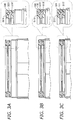
FIG. 3 ] Explanatory diagrams of an example of a production method of the battery including a preparation step (A), a sealing step (B), and a lateral crimping step (C). - A battery according to the present embodiment includes: a battery can having a cylindrical portion, a bottom wall closing one end of the cylindrical portion, and an open rim continuing to the other end of the cylindrical portion; an electrode body housed in the cylindrical portion; and a sealing body fixed to the open rim so as to seal an opening defined by the open rim.
- The sealing body includes a sealing plate and a gasket disposed at a peripheral portion of the sealing plate. The gasket is compressed between an end surface of the peripheral portion of the sealing plate and the open rim, in the radial direction of the opening. Specifically, the open rim has a pressing portion for pressing the gasket against the end surface of the peripheral portion of the sealing plate. The gasket is compressed by the pressing portion in the radial direction of the opening, and the repulsive force of the gasket acts to ensure the airtightness between the sealing body and the open rim.
- In other words, the open rim of the battery can presses the gasket not in the axial direction (hereinafter, sometimes referred to as Z direction) of the battery can but in the direction perpendicular to the Z direction (hereinafter, sometimes referred to as XY direction). In this case, given that the pressing force of the open rim exerted on the gasket is decomposed in two directions: Z and XY, the scalar quantity of the vector in the XY direction is larger than that in the Z direction.
- The open rim of the battery can may have a projection as at least part of the pressing portion, the projection protruding inward in the radial direction. In this case, the gasket is compressed in the radial direction at least by the projection. Such a projection can be formed by constricting the open rim inward. The projection may be formed intermittently in a plurality of numbers along the circumferential direction of the opening, or may be formed continuously along the circumferential direction of the opening. The continuously formed projection can form an annular groove along the circumferential direction of the opening. The projection(s) can press the gasket more strongly toward the end surface of the peripheral portion of the sealing plate. In this way, the airtightness between the sealing body and the open rim can be more reliably ensured.
- The gasket may be of any shape, and has: for example, an inner ring portion disposed on the side facing the electrode body (the inner side) of the peripheral portion of the sealing plate; and a side wall portion covering the end surface of the peripheral portion of the sealing plate. In this case, the side wall portion is compressed in the radial direction. The gasket preferably further has an outer ring portion disposed on the outer side of the peripheral portion of the sealing plate. More specifically, the gasket preferably has an outer ring portion and an inner ring portion sandwiching the peripheral portion of the sealing plate therebetween, and a side wall portion covering the end surface of the peripheral portion of the sealing plate so as to connect the outer ring portion with the inner ring portion.
- When the projection is formed intermittently in a plurality of numbers, the projections (at least two, preferably four or more projections) are provided preferably at equi-angular intervals with respect to the center of the opening.
- In a height direction of the battery can, the projection is preferably substantially equal in position to the center of the end surface of the peripheral portion of the sealing plate. By aligning the position of the projection and the center position of the end surface flush with each other, when forming the projection on the open rim of the battery, the deformation of the sealing plate can be suppressed. Moreover, the pressure applied to the gasket or its side wall portion is unlikely to be uneven. Accordingly, the deformation of the gasket tends to be suppressed, and the gasket can be compressed to a higher degree. This increases the airtightness inside the can.
- Here, that the projection is substantially equal in position to the center of the end surface of the peripheral portion of the sealing plate means that, in the height direction of the battery can, the difference between the position of the projection and the center position of the end surface of the sealing plate is 2% or less of a height H of the battery can.
- At the center position of the end surface of the peripheral portion of the sealing plate, a recessed groove may be formed so as to correspond to the projection provided on the open rim of the battery can. By providing the recessed groove, when forming the projection on the open rim of the battery, the deformation of the sealing plate can be more effectively suppressed, and the pressure applied to the gasket or its side wall portion is less likely to be uneven. The difference between the center position of the recessed groove and the position of the projection in the height direction of the battery can is 2% or less of the height H of the battery can.
- In the height direction of the battery can, the open rim may be made smaller in outer diameter at the lowermost position (the innermost position) in contact with the gasket or its inner ring portion, than the cylindrical portion. In this case, it is preferable to provide an annular cap which covers the gasket or its outer ring portion from the Z direction and covers the outer peripheral surface of the open rim of the battery can from the XY direction. The cap serves to protect the peripheral portion of the sealing plate and the open rim of the battery can. At this time, by joining the cap to the open rim, the sealing body can be more securely fixed to the battery can. The cap may be designed in such a thickness that the outer diameter of the cap becomes substantially equal to the outer diameter of the cylindrical portion.
- It is desirable that the sealing plate and the gasket are integrally molded by an insert molding technique or the like. According to the integral molding, the sealing plate and the gasket are easily welded to each other. By integrally molding the sealing plate and the gasket, the sealing body can be handled as one component, which can simplify the production of the battery.
- According to the above configuration, it is not necessary to press the gasket in the Z direction for hermetically sealing the battery can. This eliminates the necessity of providing the battery can with a constricted portion interposed between the gasket or its inner ring portion and the electrode body. Therefore, the shortest distance between the sealing body and the electrode body can be decreased, and the energy density inside the can tends to be increased. Specifically, the shortest distance between the sealing body and the electrode body can be set to, for example, 2 mm or less, and preferably 1.5 mm or less.
- A description will be given below of a battery according to an embodiment of the present invention with reference to the drawings. It is to be noted, however, the present invention is not limited thereto.
-
FIG. 1A is a schematic vertical cross-sectional view of an essential part of abattery 10 according to the present embodiment.FIG. 1B is an oblique view of the battery. Thebattery 10 has a cylindrical shape, and includes a cylindrical bottomed battery can 100, acylindrical electrode body 200 housed in the can, and a sealingbody 300 sealing the opening of the battery can 100. - The battery can 100 includes: a
cylindrical portion 120 housing theelectrode body 200; abottom wall 130 closing one end of thecylindrical portion 120; and anopen rim 110 continuing to the other end of thecylindrical portion 120. The opening defined by theopen rim 110 is closed by the sealingbody 300. - The sealing
body 300 has a sealingplate 310 and agasket 320 disposed at aperipheral portion 311 of the sealingplate 310. The sealingplate 310 is disk-shaped and has an explosion-proof function. Specifically, the sealingplate 310 includes theperipheral portion 311 and acenter region 312, both having a thick wall thickness and serving to provide structural strength, and a thin-walled portion 313 configured to exhibit an explosion-proof function. The thin-walled portion 313 is provided between theperipheral portion 311 and thecenter region 312. To the inner surface of thecenter region 312, one end of alead wire 210 extended from a positive electrode or a negative electrode constituting theelectrode body 200 is connected. Thus, the sealingplate 310 functions as a terminal of one of the electrodes. - When the internal pressure of the battery can 100 rises, the sealing
plate 310 bulges outward, and the stress due to tension is concentrated, for example, on the boundary between theperipheral portion 311 and the thin-walled portion 313, causing a break to occur from the boundary. As a result, the internal pressure of the battery can 100 is released, and the safety of thebattery 10 can be ensured. Alternatively, the sealingbody 300 comes off from theopen rim 110 and the internal pressure is released. - The sealing
plate 310 may be of any shape. In the illustrated example, theperipheral portion 311 is made thicker than thecenter region 312. The thickperipheral portion 311 can receive over a large area the pressure applied thereto from theopen rim 110 of the battery can 100 in the radial direction of the opening, allowing the stress to be easily dispersed. A recessedgroove 3111 is formed at the center position of anend surface 311T of theperipheral portion 311 so as to correspond to aprojection 111 of theopen rim 110. - The
gasket 320 has anouter ring portion 321 and aninner ring portion 322, and aside wall portion 323 connecting theouter ring portion 321 with theinner ring portion 322. Theend surface 311T of theperipheral portion 311 of the sealingplate 310 is covered with theside wall portion 323. Theouter ring portion 321 and theinner ring portion 322 sandwich theperipheral portion 311 of the sealingplate 310 therebetween, and thereby thegasket 320 is secured to the sealingplate 310. - The
outer ring portion 321, theinner ring portion 322, and theside wall portion 323 are formed as an integrally molded product. Thegasket 320 can be integrally molded with the sealingplate 310, for example, by an insert molding technique. - To ensure the airtightness between the
open rim 110 of the battery can 100 and the sealingbody 300, it is necessary that at least part of theopen rim 110 presses theside wall portion 323 of thegasket 320 against theend surface 311T of theperipheral portion 311 of the sealingplate 310, so as to compress theside wall portion 323 in the radial direction of the opening. Here, theprojection 111 protruding inward is formed on theopen rim 110 along the circumference of the opening, and theprojection 111 is pressing theside wall portion 323 against theend surface 311T. Theside wall portion 323 of thegasket 320 may be provided with a recessedportion 3231 in advance at a position corresponding to theprojection 111. Providing the recessedportion 3231 on thegasket 320 can prevent thegasket 320 from being excessively deformed when theside wall 323 is compressed. - In the height direction of the battery can 100, the
projection 111 is substantially equal in position to the center of theend surface 311T of theperipheral portion 311 of the sealingplate 310. By aligning the positions as above, the deformation of the sealingplate 310 and thegasket 320 can be suppressed, and theside wall portion 323 tends to be compressed to a higher degree. This can more reliably ensure the airtightness between the sealingbody 300 and theopen rim 110. - In the
open rim 110 of the battery can 100, the endmost portion having theend surface 110T extends in the direction forming an angle of less than 5° with the axial direction (Z direction) of the battery can 100. This prevents thegasket 320 from being subjected to excessive stress, making it possible for thegasket 320 to ensure the airtightness more easily and reliably. - The
open rim 110 of the battery can 100 is made smaller in outer diameter at the lowest position in contact with theinner ring portion 322 of thegasket 320, than thecylindrical portion 120, in the height direction of the battery can 100 of thebattery 10. Theouter ring portion 321 protrudes beyond theend surface 110T of theopen rim 110 in the axial direction (Z direction) of the battery can 100. In such a case, it is preferable to provide a protective member so as to cover theopen rim 110 of the battery can 100 and theouter ring portion 321 of thegasket 320. -
FIG. 2A is a schematic vertical cross-sectional view of an essential part of thebattery 10 including acap 400 serving as the protective member.FIG. 2B is an oblique view (a) of thecap 400 and a rear view (b) thereof, and an oblique view (c) of the battery including thecap 400. - The
annular cap 400 covers theouter ring portion 321 of thegasket 320 from the Z direction, and covers the outer peripheral surface of theopen rim 110 of the battery can 100 from the XY direction. Thecap 400 may have any thickness, and may be designed, for example, in such a thickness that the outer diameter of thecap 400 becomes substantially equal to the outer diameter of thecylindrical portion 120. A joiningmaterial 410 may be interposed between thecap 400 and the outer peripheral surface of theopen rim 110. The difference between the outer diameter or the maximum outer diameter of thecap 400 and the outer diameter or the maximum outer diameter of thecylindrical portion 120 is, for example, 20% or less of an outer diameter D of thecylindrical portion 120. The difference may be 10% or less, and may be 5% or less or 2% or less. - When the
cap 400 has electrical conductivity, thecap 400 can be configured to function as a terminal having a polarity different from that of the sealingplate 310. When thecap 400 is made function as a terminal, the other electrode having a polarity different from that of the sealingplate 310 is connected to the battery can 100. Thecap 400 is joined to theopen rim 110 by welding or the like. Thecap 400 is an accessory, the shape of which can be flexibly designed according to use. - In the
battery 10 illustrated inFIGS. 1 and2 , the battery can 100 does not have a constricted portion interposed between thegasket 320 or theinner ring portion 322 and theelectrode body 200. Therefore, the shortest distance between the sealingbody 300 and theelectrode body 200 can be reduced to, for example, 1 mm or less. - Next, a description will be given of an example of a production method of the
battery 10, with reference toFIG. 3 . - As illustrated in
FIG. 3(A) , a battery can 100 including anelectrode body 200 housed in acylindrical portion 120, and a sealingbody 300 are prepared first. Before inserting theelectrode body 200 into the can, the battery can 100 has anopen rim 110 formed sufficiently larger in diameter than theelectrode body 200. After theelectrode body 200 is housed in the can, theopen rim 110 is constricted radially, so that the outer diameter of theopen rim 110 becomes smaller than that of thecylindrical portion 120. - The sealing
body 300 can be prepared by insert-molding agasket 320 together with a sealingplate 310. The thickness of the sealingplate 310 at aperipheral portion 311 is larger than that at acenter region 312, and theperipheral portion 311 is provided with a recessedgroove 3111 at the center position of anend surface 311T. Likewise, thegasket 320 is provided with a recessedportion 3231 at a position corresponding to the recessedgroove 3111. - The
gasket 320 may be made of any material. Examples of the material include polypropylene (PP), polyphenylene sulfide (PPS), polyethylene (PE), polybutylene terephthalate (PBT), perfluoroalkoxyalkane (PFA), polytetrafluoroethylene (PTFE), and polyamide (PA). - Next, as illustrated in
FIG. 3(B) , the sealingbody 300 is disposed inside theopen rim 110 of the battery can 100. The sealingbody 300 may be positioned in any way, but can be positioned by, for example, as illustrated inFIG. 2A , using a protrudingportion 324 provided at the upper end of thegasket 320 so as to protrude outward in the radial direction of the opening. The protrudingportion 324 may be provided in a flange-like shape, or may be provided intermittently in a projection-like shape along the circumferential direction of the opening. Alternatively, a step portion may be provided on the inner side of theopen rim 110 of the battery can 100, so that the sealingbody 300 can be positioned at the step portion. - Next, as illustrated in
FIG. 3(C) , a grooving processing is applied to theopen rim 110 of the battery can 100 so as to be recessed inward at a position corresponding to the recessedgroove 3111 and the recessedportion 3231. Aprojection 111 protruding inward is thus formed on theopen rim 110, so that theprojection 111 presses theside wall portion 323 of thegasket 320 against theend surface 311T of theperipheral portion 311 of the sealingplate 310. As a result, theside wall portion 323 of thegasket 320 is compressed in the radial direction of the opening, and due to the repulsive force of thegasket 320, the airtightness between the sealingbody 300 and theopen rim 110 is ensured. - Next, an illustrative description will be given of a configuration of the
electrode body 200, with a lithium ion secondary battery taken as an example. - The
cylindrical electrode body 200 is of a wound type, and is formed by spirally winding a positive electrode and a negative electrode with a separator interposed therebetween. To one of the positive and negative electrodes, alead wire 210 is connected. Thelead wire 210 is connected to the inner surface of thecenter region 312 of the sealingplate 310 by welding or the like. To the other one of the positive and negative electrodes, another lead wire is connected. The another lead wire is connected to the inner surface of the battery can 100 by welding or the like. - The negative electrode has a belt-like negative electrode current collector and a negative electrode active material layer formed on both sides of the negative electrode current collector. The negative electrode current collector is, for example, a metal film, a metal foil, or the like. The material of the negative electrode current collector is preferably at least one selected from the group consisting of copper, nickel, titanium, alloys thereof, and stainless steel. The negative electrode current collector preferably has a thickness of, for example, 5 to 30 µm.
- The negative electrode active material layer contains a negative electrode active material, and optionally contains a binder and an electrically conductive material. The negative electrode active material layer may be a deposition film formed by a gas phase method (e.g., vapor deposition). Examples of the negative electrode active material include Li metal, a metal or an alloy that electrochemically reacts with Li, a carbon material (e.g. graphite), a silicon alloy, a silicon oxide, and a metal oxide (e.g., lithium titanate). The negative electrode active material layer preferably has a thickness of, for example, 1 to 300 µm.
- The positive electrode has a belt-like positive electrode current collector and a positive electrode active material layer formed on both sides of the positive electrode current collector. The positive electrode current collector is, for example, a metal film, a metal foil (stainless steel foil, aluminum foil, or aluminum alloy foil), or the like.
- The positive electrode active material layer contains a positive electrode active material and a binder, and optionally contains an electrically conductive material. The positive electrode active material is not limited, but may be a lithium-containing composite oxide, such as LiCoO2 or LiNiO2. The positive electrode active material layer preferably has a thickness of, for example, 1 to 300 µm.
- Examples of the conductive material contained in each active material layer include graphite and carbon black. The conductive material is contained in an amount of, for example, 0 to 20 parts by mass per 100 parts by mass of the active material. Examples of the binder contained in the active material layer include fluorocarbon resin, acrylic resin, and rubber particles. The binder is contained in an amount of, for example, 0.5 to 15 parts by mass per 100 parts by mass of the active material.
- The separator is preferably a microporous resin film or a nonwoven resin fabric. Examples of the material (resin) of the separator include polyolefin, polyamide, and polyamide imide. The separator has a thickness of, for example, 8 to 30 µm.
- The electrolyte may be a non-aqueous solvent in which a lithium salt is dissolved. Examples of the lithium salt include LiClO4, LiBF4, LiPF6, LiCF3SO3, LiCF3CO2, and imide salts. Examples of the non-aqueous solvent include: cyclic carbonic esters, such as propylene carbonate, ethylene carbonate, and butylene carbonate; chain carbonic esters, such as diethyl carbonate, ethyl methyl carbonate, and dimethyl carbonate; and cyclic carboxylic acid esters, such as γ-butyrolactone and γ-valerolactone.
- The battery according to the present invention is useful for non-aqueous electrolyte secondary batteries (esp., lithium ion secondary batteries) required to have a high energy density, and is suitably applicable as a power source for, for example, portable devices, hybrid vehicles, electric vehicles, and the like.
- Although the present invention has been described in terms of the presently preferred embodiments, it is to be understood that such disclosure is not to be interpreted as limiting. Various alterations and modifications will no doubt become apparent to those skilled in the art to which the present invention pertains, after having read the above disclosure. Accordingly, it is intended that the appended claims be interpreted as covering all alterations and modifications as fall within the true spirit and scope of the invention.
- 10: battery, 100: battery can, 110: open rim, 110T: end surface, 111: projection, 120: cylindrical portion, 130: bottom wall, 200: electrode body, 210: lead wire, 300: sealing body, 310: sealing plate, 311: peripheral portion, 311T: end surface, 3111: recessed groove, 312: center region, 313: thin-walled portion, 320: gasket, 321: outer ring portion, 322: inner ring portion, 323: side wall portion, 3231: recessed portion, 324: protruding portion, 400: cap, 410: joining material
Claims (7)
- A battery comprising:a battery can having a cylindrical portion, a bottom wall closing one end of the cylindrical portion, and an open rim continuing to the other end of the cylindrical portion; an electrode body housed in the cylindrical portion; and a sealing body fixed to the open rim so as to seal an opening defined by the open rim,the sealing body including a sealing plate and a gasket disposed at a peripheral portion of the sealing plate,the gasket being compressed between an end surface of the peripheral portion and the open rim, in a radial direction of the opening.
- The battery of claim 1, wherein the open rim has a projection protruding inward in the radial direction, and the gasket is compressed in the radial direction by the projection.
- The battery of claim 2, wherein, in a height direction of the battery can, the projection is substantially equal in position to a center of the end surface.
- The battery of any one of claims 1 to 3, wherein, in a height direction of the battery can, the open rim is smaller in outer diameter at a lowermost position in contact with the gasket, than the cylindrical portion.
- The battery of any one of claims 1 to 4, wherein the sealing plate and the gasket are integrally molded, to be welded to each other.
- The battery of any one of claims 1 to 5, wherein the battery can is configured not to have a constricted portion interposed between the gasket and the electrode body.
- The battery of any one of claims 1 to 6, wherein a shortest distance between the sealing body and the electrode body is 2 mm or less.
Applications Claiming Priority (2)
| Application Number | Priority Date | Filing Date | Title |
|---|---|---|---|
| JP2018074202 | 2018-04-06 | ||
| PCT/JP2019/014880 WO2019194253A1 (en) | 2018-04-06 | 2019-04-03 | Battery |
Publications (2)
| Publication Number | Publication Date |
|---|---|
| EP3780135A1 true EP3780135A1 (en) | 2021-02-17 |
| EP3780135A4 EP3780135A4 (en) | 2021-04-28 |
Family
ID=68100467
Family Applications (1)
| Application Number | Title | Priority Date | Filing Date |
|---|---|---|---|
| EP19780530.2A Withdrawn EP3780135A4 (en) | 2018-04-06 | 2019-04-03 | Battery |
Country Status (5)
| Country | Link |
|---|---|
| US (1) | US20210057684A1 (en) |
| EP (1) | EP3780135A4 (en) |
| JP (1) | JPWO2019194253A1 (en) |
| CN (1) | CN111937176A (en) |
| WO (1) | WO2019194253A1 (en) |
Cited By (1)
| Publication number | Priority date | Publication date | Assignee | Title |
|---|---|---|---|---|
| EP4629406A4 (en) * | 2022-11-30 | 2025-12-17 | Panasonic Energy Co Ltd | CYLINDRICAL BATTERY |
Families Citing this family (9)
| Publication number | Priority date | Publication date | Assignee | Title |
|---|---|---|---|---|
| DE102019131195A1 (en) * | 2019-11-19 | 2021-05-20 | R. Stahl Schaltgeräte GmbH | casing |
| JP7669293B2 (en) * | 2020-01-17 | 2025-04-28 | パナソニックエナジー株式会社 | Sealed battery |
| EP4123799A4 (en) * | 2020-03-16 | 2023-11-15 | SANYO Electric Co., Ltd. | CYLINDRICAL BATTERY |
| CN111584771B (en) * | 2020-05-12 | 2022-08-12 | 路华置富电子(深圳)有限公司 | Battery with safety valve cap |
| CN111564577B (en) * | 2020-05-12 | 2022-08-12 | 路华置富电子(深圳)有限公司 | Battery structure with cap support |
| US20230187746A1 (en) * | 2020-05-28 | 2023-06-15 | Sanyo Electric Co., Ltd. | Cylindrical battery |
| JP7763779B2 (en) * | 2020-11-19 | 2025-11-04 | パナソニックエナジー株式会社 | Cylindrical battery |
| US11984614B2 (en) * | 2022-02-03 | 2024-05-14 | South 8 Technologies, Inc. | Cap for electrochemical cell |
| JP7704479B2 (en) * | 2022-02-03 | 2025-07-08 | サウス エイト テクノロジーズ インク. | Caps for electrochemical cells |
Family Cites Families (15)
| Publication number | Priority date | Publication date | Assignee | Title |
|---|---|---|---|---|
| FR2276761A1 (en) * | 1974-06-28 | 1976-01-23 | Accumulateurs Fixes | WATERPROOF BOX ELECTRICAL APPLIANCE |
| FR2357076A1 (en) * | 1976-06-30 | 1978-01-27 | Cipel | CYLINDRICAL ELECTROCHEMICAL GENERATOR |
| JPS56138858A (en) * | 1980-04-01 | 1981-10-29 | Hitachi Maxell Ltd | Cylindrical alkaline battery |
| EP0037122A1 (en) * | 1980-04-01 | 1981-10-07 | Hitachi Maxell Ltd. | A cylindrical battery |
| JPS5981862A (en) * | 1982-10-30 | 1984-05-11 | Toshiba Battery Co Ltd | Alkaline battery |
| JPS59121771A (en) * | 1982-12-03 | 1984-07-13 | Toshiba Battery Co Ltd | Production method of cylindrical alakline cell |
| JPS6032246A (en) * | 1983-07-30 | 1985-02-19 | Toshiba Battery Co Ltd | Alkaline battery |
| JPS63228564A (en) * | 1987-03-18 | 1988-09-22 | Fuji Elelctrochem Co Ltd | Cartridge cell |
| JPH07105933A (en) | 1993-10-06 | 1995-04-21 | Hitachi Maxell Ltd | Explosion-proof sealed battery |
| JPH10199495A (en) * | 1997-01-09 | 1998-07-31 | Mitsubishi Cable Ind Ltd | Sealed structure of sealed battery and gasket used for it |
| JP4861630B2 (en) * | 2005-02-10 | 2012-01-25 | Fdkエナジー株式会社 | Cylindrical sealed battery gasket, battery, and manufacturing method |
| KR101040976B1 (en) * | 2008-10-14 | 2011-06-16 | 주식회사 엘지화학 | Cylindrical battery without bead |
| US20100216014A1 (en) * | 2009-02-24 | 2010-08-26 | Eveready Battery Company, Inc. | Closure Assembly for Electrochemical Cells |
| KR101514827B1 (en) * | 2013-02-26 | 2015-04-23 | 주식회사 엘지화학 | Secondary battery and method for manufacturing the same |
| KR102235281B1 (en) * | 2014-09-12 | 2021-04-02 | 삼성에스디아이 주식회사 | Rechargeable battery |
-
2019
- 2019-04-03 US US17/045,212 patent/US20210057684A1/en not_active Abandoned
- 2019-04-03 CN CN201980023492.7A patent/CN111937176A/en active Pending
- 2019-04-03 EP EP19780530.2A patent/EP3780135A4/en not_active Withdrawn
- 2019-04-03 WO PCT/JP2019/014880 patent/WO2019194253A1/en not_active Ceased
- 2019-04-03 JP JP2020512305A patent/JPWO2019194253A1/en active Pending
Cited By (1)
| Publication number | Priority date | Publication date | Assignee | Title |
|---|---|---|---|---|
| EP4629406A4 (en) * | 2022-11-30 | 2025-12-17 | Panasonic Energy Co Ltd | CYLINDRICAL BATTERY |
Also Published As
| Publication number | Publication date |
|---|---|
| EP3780135A4 (en) | 2021-04-28 |
| US20210057684A1 (en) | 2021-02-25 |
| WO2019194253A1 (en) | 2019-10-10 |
| JPWO2019194253A1 (en) | 2021-04-01 |
| CN111937176A (en) | 2020-11-13 |
Similar Documents
| Publication | Publication Date | Title |
|---|---|---|
| EP3780135A1 (en) | Battery | |
| US12512537B2 (en) | Battery | |
| US20210043879A1 (en) | Battery | |
| US12573721B2 (en) | Battery module | |
| US12308446B2 (en) | Battery | |
| US20120225348A1 (en) | Secondary battery | |
| US11881550B2 (en) | Battery | |
| US12068489B2 (en) | Battery | |
| US12512542B2 (en) | Sealing body and battery | |
| US12212008B2 (en) | Battery | |
| US12288886B2 (en) | Battery | |
| EP4693634A1 (en) | Power storage device |
Legal Events
| Date | Code | Title | Description |
|---|---|---|---|
| STAA | Information on the status of an ep patent application or granted ep patent |
Free format text: STATUS: THE INTERNATIONAL PUBLICATION HAS BEEN MADE |
|
| PUAI | Public reference made under article 153(3) epc to a published international application that has entered the european phase |
Free format text: ORIGINAL CODE: 0009012 |
|
| STAA | Information on the status of an ep patent application or granted ep patent |
Free format text: STATUS: REQUEST FOR EXAMINATION WAS MADE |
|
| 17P | Request for examination filed |
Effective date: 20200930 |
|
| AK | Designated contracting states |
Kind code of ref document: A1 Designated state(s): AL AT BE BG CH CY CZ DE DK EE ES FI FR GB GR HR HU IE IS IT LI LT LU LV MC MK MT NL NO PL PT RO RS SE SI SK SM TR |
|
| AX | Request for extension of the european patent |
Extension state: BA ME |
|
| A4 | Supplementary search report drawn up and despatched |
Effective date: 20210330 |
|
| RIC1 | Information provided on ipc code assigned before grant |
Ipc: H01M 10/04 20060101AFI20210324BHEP Ipc: H01M 50/107 20210101ALI20210324BHEP Ipc: H01M 50/152 20210101ALI20210324BHEP Ipc: H01M 50/166 20210101ALI20210324BHEP Ipc: H01M 50/184 20210101ALI20210324BHEP Ipc: H01M 50/186 20210101ALI20210324BHEP |
|
| DAV | Request for validation of the european patent (deleted) | ||
| DAX | Request for extension of the european patent (deleted) | ||
| STAA | Information on the status of an ep patent application or granted ep patent |
Free format text: STATUS: THE APPLICATION IS DEEMED TO BE WITHDRAWN |
|
| 18D | Application deemed to be withdrawn |
Effective date: 20211027 |