EP3780062A1 - Current management device and voltage distribution unit - Google Patents
Current management device and voltage distribution unit Download PDFInfo
- Publication number
- EP3780062A1 EP3780062A1 EP20186435.2A EP20186435A EP3780062A1 EP 3780062 A1 EP3780062 A1 EP 3780062A1 EP 20186435 A EP20186435 A EP 20186435A EP 3780062 A1 EP3780062 A1 EP 3780062A1
- Authority
- EP
- European Patent Office
- Prior art keywords
- management device
- current management
- distribution unit
- voltage distribution
- locking mechanism
- Prior art date
- Legal status (The legal status is an assumption and is not a legal conclusion. Google has not performed a legal analysis and makes no representation as to the accuracy of the status listed.)
- Pending
Links
Images








Classifications
-
- H—ELECTRICITY
- H01—ELECTRIC ELEMENTS
- H01H—ELECTRIC SWITCHES; RELAYS; SELECTORS; EMERGENCY PROTECTIVE DEVICES
- H01H85/00—Protective devices in which the current flows through a part of fusible material and this current is interrupted by displacement of the fusible material when this current becomes excessive
- H01H85/02—Details
- H01H85/0241—Structural association of a fuse and another component or apparatus
-
- H—ELECTRICITY
- H01—ELECTRIC ELEMENTS
- H01H—ELECTRIC SWITCHES; RELAYS; SELECTORS; EMERGENCY PROTECTIVE DEVICES
- H01H9/00—Details of switching devices, not covered by groups H01H1/00 - H01H7/00
- H01H9/10—Adaptation for built-in fuses
Definitions
- the present specification relates to a current management device and a voltage distribution unit for use with the current management device in an electricity supply network, and relates particularly, but not exclusively, to support, guidance and locking mechanisms of the current management device and voltage distribution unit.
- Voltage distribution units distribute electrical power in electricity supply networks, and the current flowing through the voltage distribution units is monitored and controlled by current management devices installed in the voltage distribution units.
- Current management devices can be a simple fuse, designed to create a break in a circuit in the event of the current passing through the fuse exceeding a predetermined threshold, or can include a circuit breaker and associated electronic circuitry for monitoring the current and introducing the break in the circuit either automatically or via remote control.
- a current management device for use with a voltage distribution unit, comprising: a plurality of electrical contacts for engaging corresponding electrical contacts of the voltage distribution unit; at least two support members configured to slide along corresponding support members of the voltage distribution unit to support the current management device and guide the electrical contacts of the current management device and voltage distribution unit into mutual engagement during insertion of the current management device into the voltage distribution unit; and at least one locking mechanism for engaging a respective at least one locking mechanism of the voltage distribution unit, the at least one locking mechanism being configured to move the respective at least one locking mechanism of the voltage distribution unit into a locking configuration as the support members slide along the corresponding support members, wherein the at least one locking mechanism is further configured to maintain the plurality of electrical contacts in electrical connection with the corresponding electrical contacts of the voltage distribution unit while in the locking configuration.
- the weight of the current management device can be supported by the co-operation during insertion and removal of the current management device into and from the voltage distribution unit, thereby providing the advantages of increased ease of insertion and removal, increased consistency of electrical connection upon installation, and increased safety.
- a current management device having a locking mechanism configured to move a respective locking mechanism of the voltage distribution unit into a locking configuration as support members of the current management device slide along corresponding support members of the voltage distribution unit, wherein the locking mechanism maintains the electrical contacts of the current management device in electrical connection with the corresponding electrical contacts of the voltage distribution unit while in the locking configuration
- the safety of the installing user and to subsequent users working with the device and/or unit is increased by eliminating the need to rely on an installing user to manually engage a locking mechanism to maintain the current management device in a locked electrical connection within the voltage distribution unit. Therefore, in the event of an electrical fault or other malfunction, the current management device is less likely to be ejected from the voltage distribution unit and electrical connection between the device and the unit is more likely to be maintained.
- the current management device may comprise an enclosure. At least two support members may be arranged on opposite exterior faces of the enclosure.
- the housing can protect the inner workings of the current management device from damage while maintaining the above advantages.
- At least one support member of the current management device may comprise a support member abutment for abutting at least one support member of the voltage distribution unit to prevent egress of the current management device from the voltage distribution unit.
- this can provide the advantage of decreasing the likelihood of the current management device from slipping or being dropped from the voltage distribution unit, and at the final stage of removal of the current management device from the voltage distribution unit, this can provide the advantage of informing the user that the current management device is almost completely removed so that the user knows to take the weight of the current management device, thereby further decreasing the likelihood of dropping the current management device.
- the current management device may comprise at least four support members. Two support members may be arranged on a first exterior face of the enclosure and two support members may be arranged on a second exterior face of the enclosure opposite the first exterior face.
- the current management device may further comprise at least one abutment for engaging at least one respective locking mechanism of the voltage distribution unit in a locked configuration to prevent egress of the current management device from the voltage distribution unit.
- a surface of the at least one abutment may be oriented substantially perpendicular to at least one support member of the current management device.
- the current management device may further comprise at least one ramp for guiding at least one respective locking mechanism into the locked configuration.
- At least one ramp may comprise at least one abutment and define a corner between the ramp and the abutment.
- the current management device may further comprise at least one lever pivotably attached to the current management device for engaging at least one of the respective locking mechanisms of the voltage distribution unit to cause the at least one locking mechanism to move out of the locked configuration and into an unlocked configuration, thereby enabling removal of the current management device from the voltage distribution unit.
- a voltage distribution unit comprising: a plurality of electrical contacts for engaging corresponding electrical contacts of a current management device; at least two support members configured to slidably receive corresponding support members of the current management device to support the current management device and guide the electrical contacts of the voltage distribution unit and current management device into mutual engagement during insertion of the current management device into the voltage distribution unit; and at least one locking mechanism for engaging a respective at least one locking mechanism of the current management device, the at least one locking mechanism being configured to be moved by the respective at least one locking mechanism of the current management device into a locking configuration as the support members of the current management device slide along the support members of the voltage distribution unit, wherein the at least one locking mechanism is further configured to maintain the plurality of electrical contacts in electrical connection with the corresponding electrical contacts of the current management device while in the locking configuration.
- automatic locking increases the safety to the installing user, as well as subsequent users, by eliminating the need to rely on an installing user to manually engage a locking mechanism having installed the current management device in electrical connection with the voltage distribution unit. Therefore, in the event of an electrical fault or other malfunction, the current management device is less likely to be ejected from the voltage distribution unit and electrical connection between the device and the unit is more likely to be maintained.
- the at least two support members of the voltage distribution unit may be arranged on opposite interior faces of the voltage distribution unit.
- the voltage distribution unit may further comprise at least one aperture, wherein at least one locking mechanism may be slidable along at least one said aperture.
- the at least one locking mechanism may comprise a first surface for engaging a ramp of the current management device to cause the locking mechanism to slide along the aperture.
- the at least one locking mechanism may comprise and a second surface for engaging the current management device in a locked configuration.
- the at least one locking mechanism may comprise a top surface for engaging a respective lever of the current management device, such that action of the lever on the top surface causes the at least one locking mechanism to move along at least one respective aperture to move the at least one locking mechanism into an unlocked configuration.
- the second surface may be configured to abut an abutment of the current management device in the locked configuration to prevent egress of the current management device from the voltage distribution unit.
- the voltage distribution unit may further comprise biasing means for biasing at least one locking mechanism toward a first position.
- a system comprising a current management device as described above and a voltage distribution unit as described above.
- a current management device 10 is shown installed in a voltage distribution unit 12.
- the current management device 10 is shown comprising a housing 14 which encloses internal parts of the current management device 10, which are described in detail below.
- the current management device 10 is shown in an installed state, installed in a first compartment 16 of the voltage distribution unit 12. It is to be understood that the current management device 10 could instead be installed in the second compartment 18, the third compartment 20, or in any other suitable compartment if the voltage distribution unit 12 has more than three such compartments.
- the current management device 10 comprises a lever 22 pivotably attached at a pivot point 24 located in the housing 14 of the current management device 10.
- the lever 22 comprises an arm 26 and a handle 28.
- the handle 28 is joined to the arm 26 at a corner 30.
- a portion of the arm 26 passes beneath the housing 14 of the current management device 10 between the pivot point 24 and the corner 30.
- a similar lever 22 is pivotably attached to the opposite side of the device 10.
- the handles 28 of the levers 22 may be joined to one another to form a single, U-shaped handle (not shown) which operates both arms simultaneously.
- the current management device comprises first support members in the form of bars 32.
- the current management device has four bars 32, and the bars 32 are located on opposite exterior faces 34, 36 of the housing 14.
- the bars 32 each include a knob 38 at the end of the bar 32 nearest to the voltage distribution unit 12 during installation.
- the knobs 38 are shown having a curved face 40 and a support member abutment in the form of a flat face 42, each flat face 42 oriented vertically in situ.
- each compartment 16, 18, 20 comprises shelves 44, though it is to be understood that the voltage distribution unit 12 may include one or more compartments that do not have shelves 44.
- each compartment 16, 18, 20 comprises four shelves 44 located on opposite interior faces 46, 48 of the compartments 16, 18, 20.
- the current management device 10 is shown comprising two electrical contacts in the form of elongate blades 50.
- the voltage distribution unit 12 is shown comprising two electrical contacts in the form of pairs of plates 52 arranged to pinch respective blades 50 under the action of biasing means in the form of leaf springs 54 (see also Figure 10 ) to achieve a reliable electrical connection between the current management device 10 and the voltage distribution unit 12.
- the current management device 12 is shown comprising locking mechanisms in the form of ramps 56 and abutments, the abutments in the form of flat faces 58.
- the flat faces 58 are oriented vertically in situ.
- the ramps 56 and the abutments are integrally formed and are so formed on exterior faces 34, 36 of the housing.
- the relative arrangement of the arms 26, ramps 56, and faces 56 in the installed state is shown in Figures 3 and 12 .
- the voltage distribution unit 12 is shown comprising a plurality of apertures 60.
- the apertures 60 are located through the compartments 16, 18, 20, are elongate in shape, and have long axes oriented perpendicularly to long axes of the bars 32 and shelves 44.
- Shown slidably arranged within the apertures 60 are locking mechanisms 62 of the voltage distribution unit, are also shown in Figures 1 to 5 and 10 to 12 , which are described in detail below.
- a fuse carrier 64 is shown installed in compartments (18, 20) of the voltage distribution unit 12. The operation of the fuse carrier 64 is not the focus of the present invention and will therefore not be described in any further detail.
- the current management device 10 is shown without its housing 14.
- the current management device 10 comprises a circuit breaker 66, an insulated board 68, a fuse assembly 70, cooling fins 72, and two pairs of plate contacts 74.
- First and second pairs of plate contacts 74A, 74B grip sections 76A, 76B of respective first and second blades 78A, 78B.
- the sections 76A, 76B are joined to the blades 78A, 78B by curved portions 80A, 80B so that each blade 78A, 78B lies in a plane substantially perpendicular to a plane in which a respective section 76A, 76B lies.
- blades not having curved portions, or instead having straight portions may be installed in the plate contacts 74A, 74B instead, such that such blades lie in places substantially parallel to the planes in which respective sections lie.
- This arrangement is suitable where the voltage distribution unit 12 includes corresponding electrical contacts which are arranged vertically (such as European DIN configurations, which are well known to those skilled in the art).
- the first blade 78A is in electrical communication with the circuit breaker 66 via first electrical connectors 82
- the second blade 78B is in electrical communication with the circuit breaker 66 via second electrical connectors 84.
- the insulated board 68 electrically isolates the first blade 78A and first electrical connectors 82 from the second blade 78B and second electrical connectors 84 and provides a mounting surface for the fuse assembly 70, which in these embodiments is shown electrically connected between the second electrical connectors 84 and the second blade 78B.
- the fuse assembly 70 comprises a cylindrical fuse body 86 and fuse housing 88.
- the fuse assembly 70 is removable from the current management device 10 for replacement as and when required.
- the circuit breaker 66 comprises circuit breaker housing 90 which encloses programmable electronic circuitry for operation, control, and monitoring of the current management device 10 in a manner well understood by those skilled in the art.
- the current management device 10 is located within compartment 16 of the voltage distribution unit 12 and bars 32 contact shelves 44 of the interior of the compartment 16 (see Figure 15 ).
- Lower bars 32L are located above lower shelves 44L, which enables the lower shelves 44L to support the weight of the current management device 10, thus facilitating the installation process by reducing the physical effort required by an installer in guiding the current management device 10 into the compartment 16.
- Upper bars 32U are located beneath upper shelves 44U and provide a continuous hard stop to the upper bars 32U in the event that the current management device 10 pivots about a contact point between a lower bar 32L and a lower shelf 44L during installation, thereby further increasing the ease of installation by further reducing the physical effort required to keep the current management device 10 in a correct installation orientation.
- the curved faces 40 of knobs 38 of the bars 32 increase the ease with which the user initially locates the bars 32 between the shelves 44L by providing a correcting sliding action into a correct location and orientation if the current management device 10 is not correctly located or oriented in the first instance.
- the flat faces 42 of the knobs 38 abut corresponding flat faces 92 of the lower shelves 44L if the current management device 10 is accidentally pulled backwards out of the compartment 16. This decreases the likelihood of dropping and potentially damaging the current management device 10.
- Installation proceeds by pushing the current management device 10 further into the compartment 16. As installation proceeds, the bars 32 slide along the shelves 44 and the blades 50 move towards plates 52 of the voltage distribution unit 12. The relative locations of the bars 32 and blades 50 are chosen such that, as the bars 32 of the current management device 10 slide along the shelves 44 of the voltage distribution unit 12, the blades 50 are guided directly into electrical engagement with respective pairs of plates 52 as installation is completed. In this way reliable, consistent and safe installation of the current management device 10 is achieved.
- Locking mechanisms 62 are shown, without illustration of the compartments 16, 18, 20 and apertures 60 for clarity, in Figures 10 to 12 , 16 , 18 , and 19 . Locking mechanisms 62 are shown in Figure 14 located in apertures 60. A locking mechanism is shown in Figure 17 located in an aperture 60.
- ramps 56 move toward respective locking mechanisms 62.
- each locking mechanism 62 comprises an engagement portion 96 having a top surface 98 for engaging an arm 26, a first side surface 100 for engaging a surface of a ramp 56, and an abutment in the form of second side surface 102 for engaging the flat face 58.
- the engagement portion 96 of each locking mechanism 62 is attached to a sliding portion 104.
- Each sliding portion 104 is dimensioned to fit within a respective aperture 60 and to slide along a channel having first end 94 and second end 106 defined by that aperture 60.
- Each engagement portion 96 is also attached to an elongate rectangular portion 108 having a slot 110.
- a locking mechanism 62 is shown comprising an angled tab 112 which abuts a wall 114 of the aperture 60 at the first end 94 of the aperture to stop the locking mechanism 62 from travelling further upwards along the aperture 60, thereby preventing the locking mechanism 62 from falling out of the aperture 60.
- the angled tab 112 is moveably attached to the locking mechanism 62 so that the angled tab 112 can be pushed into the slot 110 of the elongate portion 108 by a user or suitable tool for removal of the locking mechanism 62 from the aperture.
- a similar tab is installed within the other locking mechanism 62.
- biasing means in the form of a spring 116 is shown installed in a cavity 118 of a locking mechanism 62.
- the cavity 118 is shown formed within the sliding portion 104 of the locking mechanism 62.
- the spring 116 is installed between an end of the cavity 118 and a plunger 120.
- the spring 116 biases the locking mechanism 62 upwards towards the first end 94 of the aperture 60.
- the spring 116 is compressed toward the plunger 120 by downward motion of the locking mechanism 62 relative to the voltage distribution unit 12.
- a similar spring (not shown) is installed within the other locking mechanism 62 (see Figure 14 ).
- the ramps 56 engages the first side surfaces 98 of the engagement portions 96. This causes the locking mechanisms 62 to slide downward from first ends 94 in the apertures 60 towards second ends 106 against the action of the springs 116. As the current management device 10 is pushed further into the compartment 16, the second side surfaces 102 eventually pass the flat faces 58 of the ramps 56 and the locking mechanisms 62 become free to slide upwards along the apertures 60 back towards the first ends 94.
- the ramps 56 and flat faces 58 constitute an embodiment of a locking mechanism of the current management device 10.
- the locking mechanism of the current management device 10 interacts with the locking mechanism 62 of the voltage distribution unit to bring the unit and the device into a locked configuration as the device 10 is slid into the voltage distribution unit, without requiring an installer to manipulate the locking mechanisms themselves.
- the current management device 10 is thereby installed in the voltage distribution unit in a locked configuration. In the locked configuration, the current management device is prevented from being ejected or otherwise withdrawn from the voltage distribution unit.
- Figure 12 shows a close-up view of the locked configuration.
- the levers 22 act to move the locking mechanisms 62 along the apertures 60 against the action of the springs 116 to unlock the current management device 10 from the compartment 16.
- portions of arms 26 of the levers 22 are located above top surfaces 98 of the engagement portions 96.
- Lifting of the handles 28 of the levers 22, that is application of a moment of the levers 22 about pivot points 24, causes the arms 26 to push downward on the top surfaces 98 of the engagement portions 96 against the action of the springs 116.
- the moment is anticlockwise about the pivot point 24 shown.
- the applied moment causes the arms 26 to push the locking mechanisms 62 downward along the channels defined by the apertures 60 until the second side surfaces 102 of the engagement portions 96 clear the flat faces 58 of the ramps 56. Once the second side surfaces 102 clear the flat faces 58, the engagement portions 96 of the locking mechanisms 62 no longer abut the flat faces 56 of the housing 14 to prevent egress of the current management device 10 from the compartment 16, so the current management device 10 is now in an unlocked configuration and can be pulled out of the compartment 16.
- the locking mechanisms 62 slide down the ramps 56 without hindering the egress of the current management device 10 and the locking mechanisms 62 return to the first ends 94 of their respective apertures 60 ready for a subsequent installation if desired.
- a current management device for use with a voltage distribution unit, comprising: blades for engaging corresponding plates of the voltage distribution unit; and bars configured to slide along corresponding shelves of the voltage distribution unit to support the current management device and guide the blades of the current management device and plates of the voltage distribution unit into mutual engagement during insertion of the current management device into the voltage distribution unit, a voltage distribution unit comprising plates for engaging blades of a current management device; shelves configured to slidably receive bars of the current management device to support the current management device and guide the plates of the voltage distribution unit and blades of the current management device into mutual engagement during insertion of the current management device into the voltage distribution unit, and a system comprising the current management device installed in the voltage distribution unit.
Landscapes
- Engineering & Computer Science (AREA)
- Power Engineering (AREA)
- Details Of Connecting Devices For Male And Female Coupling (AREA)
- Fuses (AREA)
Abstract
Description
- The present specification relates to a current management device and a voltage distribution unit for use with the current management device in an electricity supply network, and relates particularly, but not exclusively, to support, guidance and locking mechanisms of the current management device and voltage distribution unit.
- Voltage distribution units distribute electrical power in electricity supply networks, and the current flowing through the voltage distribution units is monitored and controlled by current management devices installed in the voltage distribution units. Current management devices can be a simple fuse, designed to create a break in a circuit in the event of the current passing through the fuse exceeding a predetermined threshold, or can include a circuit breaker and associated electronic circuitry for monitoring the current and introducing the break in the circuit either automatically or via remote control.
- Installing and removing current management devices in and from voltage distribution units can be physically difficult, as current management devices can be bulky and heavy, and dangerous, as the electrical currents involved can be lethally high and can even cause abrupt ejection of the current management devices under electrical fault conditions, such as when a sudden change in current flow causes the generation of a large magnetic force.
- Conventionally, current management devices are held in an installed position within a voltage distribution unit by clamping electrical contacts of one of the current management device and voltage distribution unit between corresponding electrical contacts of the other. This requires mechanical apparatus for performing the clamping to be included in one or more of the current management device and voltage distribution unit, which has associated manufacturing, maintenance, and assembly costs and involves a certain amount of time an installer must spend installing or uninstalling the current management device. An example of such a clamping mechanism is described in International Patent Application
WO 2016/042290 A1 . - Aspects of the present disclosure are set out in the accompanying independent and dependent claims. Combinations of features from the dependent claims may be combined with features of the independent claims as appropriate and not merely as explicitly set out in the claims.
- According to an aspect of the present disclosure, there is provided a current management device for use with a voltage distribution unit, comprising: a plurality of electrical contacts for engaging corresponding electrical contacts of the voltage distribution unit; at least two support members configured to slide along corresponding support members of the voltage distribution unit to support the current management device and guide the electrical contacts of the current management device and voltage distribution unit into mutual engagement during insertion of the current management device into the voltage distribution unit; and at least one locking mechanism for engaging a respective at least one locking mechanism of the voltage distribution unit, the at least one locking mechanism being configured to move the respective at least one locking mechanism of the voltage distribution unit into a locking configuration as the support members slide along the corresponding support members, wherein the at least one locking mechanism is further configured to maintain the plurality of electrical contacts in electrical connection with the corresponding electrical contacts of the voltage distribution unit while in the locking configuration.
- By providing a current management device having support members which co-operate with support members of a voltage distribution unit, the weight of the current management device can be supported by the co-operation during insertion and removal of the current management device into and from the voltage distribution unit, thereby providing the advantages of increased ease of insertion and removal, increased consistency of electrical connection upon installation, and increased safety. By providing a current management device having a locking mechanism configured to move a respective locking mechanism of the voltage distribution unit into a locking configuration as support members of the current management device slide along corresponding support members of the voltage distribution unit, wherein the locking mechanism maintains the electrical contacts of the current management device in electrical connection with the corresponding electrical contacts of the voltage distribution unit while in the locking configuration, the safety of the installing user and to subsequent users working with the device and/or unit is increased by eliminating the need to rely on an installing user to manually engage a locking mechanism to maintain the current management device in a locked electrical connection within the voltage distribution unit. Therefore, in the event of an electrical fault or other malfunction, the current management device is less likely to be ejected from the voltage distribution unit and electrical connection between the device and the unit is more likely to be maintained.
- The current management device may comprise an enclosure. At least two support members may be arranged on opposite exterior faces of the enclosure.
- The housing can protect the inner workings of the current management device from damage while maintaining the above advantages.
- At least one support member of the current management device may comprise a support member abutment for abutting at least one support member of the voltage distribution unit to prevent egress of the current management device from the voltage distribution unit.
- Immediately upon initial insertion of the current management device into the voltage distribution unit, this can provide the advantage of decreasing the likelihood of the current management device from slipping or being dropped from the voltage distribution unit, and at the final stage of removal of the current management device from the voltage distribution unit, this can provide the advantage of informing the user that the current management device is almost completely removed so that the user knows to take the weight of the current management device, thereby further decreasing the likelihood of dropping the current management device.
- The current management device may comprise at least four support members. Two support members may be arranged on a first exterior face of the enclosure and two support members may be arranged on a second exterior face of the enclosure opposite the first exterior face.
- This can provide the advantage of evenly distributing the weight of the current management device and preventing the current management device from rotating during insertion, thereby further increasing the consistency of electrical connection upon installation.
- The current management device may further comprise at least one abutment for engaging at least one respective locking mechanism of the voltage distribution unit in a locked configuration to prevent egress of the current management device from the voltage distribution unit.
- This can prevent the current management device from being ejected from the voltage distribution unit in the event of, for example, vibrations or an electrical fault producing a magnetic force, thereby increasing user safety and preventing other collateral damage.
- A surface of the at least one abutment may be oriented substantially perpendicular to at least one support member of the current management device.
- This can increase the effectiveness of the abutment in keeping the current management device in place.
- The current management device may further comprise at least one ramp for guiding at least one respective locking mechanism into the locked configuration.
- This can enable a smooth insertion action for the locking to take place, such that a user does not have to manually interact with the locking mechanism, thereby providing the advantages of increasing the ease of achieving a successful installation and increasing user safety.
- At least one ramp may comprise at least one abutment and define a corner between the ramp and the abutment.
- This can enable the ramp and abutment to be integrally formed, thereby reducing manufacturing costs.
- The current management device may further comprise at least one lever pivotably attached to the current management device for engaging at least one of the respective locking mechanisms of the voltage distribution unit to cause the at least one locking mechanism to move out of the locked configuration and into an unlocked configuration, thereby enabling removal of the current management device from the voltage distribution unit.
- This can enable a user to unlock the current management device from the voltage distribution unit without having to touch any part of the voltage distribution unit, thereby further increasing user safety.
- According to another aspect of the present disclosure, there is provided a voltage distribution unit, comprising: a plurality of electrical contacts for engaging corresponding electrical contacts of a current management device; at least two support members configured to slidably receive corresponding support members of the current management device to support the current management device and guide the electrical contacts of the voltage distribution unit and current management device into mutual engagement during insertion of the current management device into the voltage distribution unit; and at least one locking mechanism for engaging a respective at least one locking mechanism of the current management device, the at least one locking mechanism being configured to be moved by the respective at least one locking mechanism of the current management device into a locking configuration as the support members of the current management device slide along the support members of the voltage distribution unit, wherein the at least one locking mechanism is further configured to maintain the plurality of electrical contacts in electrical connection with the corresponding electrical contacts of the current management device while in the locking configuration.
- This can enable current management devices to be installed in the voltage distribution unit more easily and more safely and increases the consistency of electrical connection while providing for automatic locking of the current management device in place within the voltage distribution unit. Such automatic locking increases the safety to the installing user, as well as subsequent users, by eliminating the need to rely on an installing user to manually engage a locking mechanism having installed the current management device in electrical connection with the voltage distribution unit. Therefore, in the event of an electrical fault or other malfunction, the current management device is less likely to be ejected from the voltage distribution unit and electrical connection between the device and the unit is more likely to be maintained.
- The at least two support members of the voltage distribution unit may be arranged on opposite interior faces of the voltage distribution unit.
- This can provide the advantage of reducing stress on the voltage distribution unit by distributing the weight of the current management device.
- The voltage distribution unit may further comprise at least one aperture, wherein at least one locking mechanism may be slidable along at least one said aperture. The at least one locking mechanism may comprise a first surface for engaging a ramp of the current management device to cause the locking mechanism to slide along the aperture. The at least one locking mechanism may comprise and a second surface for engaging the current management device in a locked configuration.
- This can enable a smooth insertion action for the locking to take place, such that a user does not have to manually interact with the locking mechanism, thereby providing the advantages of increasing the ease of achieving a successful installation and increasing user safety.
- The at least one locking mechanism may comprise a top surface for engaging a respective lever of the current management device, such that action of the lever on the top surface causes the at least one locking mechanism to move along at least one respective aperture to move the at least one locking mechanism into an unlocked configuration.
- This can enable a user to unlock the current management device from the voltage distribution unit without having to touch any part of the voltage distribution unit, thereby further increasing user safety.
- The second surface may be configured to abut an abutment of the current management device in the locked configuration to prevent egress of the current management device from the voltage distribution unit.
- This can provide a mechanically simple action for maintaining the current management device in the locked configuration, thereby reducing manufacturing and maintenance costs.
- The voltage distribution unit may further comprise biasing means for biasing at least one locking mechanism toward a first position.
- This can enable the locking mechanism to be kept in and automatically returned to an initial position in its aperture, thereby enabling subsequent installations of current management devices to take place without requiring the locking mechanism to be reset, which can provide the advantage of increased user safety and increased ease of use.
- According to a further aspect of the present disclosure, there is provided a system comprising a current management device as described above and a voltage distribution unit as described above.
- Embodiments of this disclosure will be described hereinafter, by way of example only, with reference to the accompanying drawings in which like reference signs relate to like elements and in which:
-
Figure 1 is an isometric view of a current management device installed in a voltage distribution unit according to an embodiment of this disclosure; -
Figure 2 is an isometric view of the current management device and distribution unit ofFigure 1 with a fuse carrier shown installed in a compartment of the voltage distribution unit; -
Figure 3 is a partially cut-away view of the current management device and distribution unit ofFigure 1 with the fuse carrier shown installed in a different compartment of the voltage distribution unit; -
Figure 4 is a different view of the current management device and distribution unit ofFigure 2 ; -
Figure 5 is a front view of the current management device and distribution unit ofFigure 1 ; -
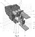
Figure 6 is an isometric view of a current management device according to an embodiment of this disclosure; -
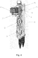
Figure 7 is an isometric view of the current management device ofFigure 6 rotated 180 degrees about its longitudinal axis; -
Figure 8 is a top view of the current management device ofFigure 6 ; -
Figure 9 is an end view of the current management device ofFigure 6 ; -
Figure 10 is a partially cut-away view of a current management device installed in a voltage distribution unit according to an embodiment of this disclosure; -
Figure 11 is a close-up view of a current management device according to an embodiment of this disclosure in an uninstalled state; -
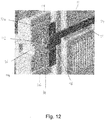
Figure 12 is a close-up view of a current management device according to an embodiment of this disclosure in an installed state; -
Figure 13 is a close-up view of a current management device according to an embodiment of this disclosure; -
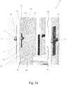
Figure 14 is a close-up view of a portion of a voltage distribution unit according to an embodiment of this disclosure; -
Figure 15 is a partially transparent side view of a current management device according to an embodiment of this disclosure; -
Figure 16 is a partially transparent isometric view of a current management device and voltage distribution unit according to an embodiment of this disclosure; -
Figure 17 is a close-up and partially transparent view of a locking mechanism of a voltage distribution unit according to an embodiment of this disclosure; -
Figure 18 is a side and partially transparent view of the locking mechanism ofFigure 17 ; and -
Figure 19 is an isometric view of the locking mechanism ofFigure 17 . - Embodiments of this disclosure are described in the following with reference to the accompanying drawings. The following table lays out which features are indicated by which reference numerals.
- 10
- current management device
- 12
- voltage distribution unit
- 14
- housing
- 16
- first compartment
- 18
- second compartment
- 20
- third compartment
- 22
- lever
- 24
- pivot point
- 26
- arm
- 28
- handle
- 30
- corner
- 32
- bar (first support member)
- 34
- exterior face
- 36
- exterior face
- 38
- knob
- 40
- curved face
- 42
- flat face
- 44
- shelf (second support member)
- 46
- interior face
- 48
- interior face
- 50
- blade (electrical contact)
- 52
- pair of plates (electrical contact)
- 54
- leaf spring
- 56
- ramp
- 58
- flat face
- 60
- aperture
- 62
- locking mechanism
- 64
- fuse carrier
- 66
- circuit breaker
- 68
- insulated board
- 70
- fuse assembly
- 72
- cooling fin
- 74
- pair of plate contacts
- 76
- section
- 78
- blade
- 80
- curved portion
- 82
- first electrical connector
- 84
- second electrical connector
- 86
- fuse body
- 88
- fuse housing
- 90
- circuit breaker housing
- 92
- flat face
- 94
- first end
- 96
- engagement portion
- 98
- top surface
- 100
- first side surface
- 102
- second side surface
- 104
- sliding portion
- 106
- second end
- 108
- elongate rectangular portion
- 110
- slot
- 112
- tab
- 114
- wall
- 116
- spring
- 118
- cavity
- 120
- plunger
- Referring to
Figures 1 to 5 , acurrent management device 10 is shown installed in avoltage distribution unit 12. Thecurrent management device 10 is shown comprising ahousing 14 which encloses internal parts of thecurrent management device 10, which are described in detail below. - The
current management device 10 is shown in an installed state, installed in afirst compartment 16 of thevoltage distribution unit 12. It is to be understood that thecurrent management device 10 could instead be installed in thesecond compartment 18, thethird compartment 20, or in any other suitable compartment if thevoltage distribution unit 12 has more than three such compartments. - The
current management device 10 comprises alever 22 pivotably attached at apivot point 24 located in thehousing 14 of thecurrent management device 10. Thelever 22 comprises anarm 26 and ahandle 28. Thehandle 28 is joined to thearm 26 at acorner 30. A portion of thearm 26 passes beneath thehousing 14 of thecurrent management device 10 between thepivot point 24 and thecorner 30. Asimilar lever 22 is pivotably attached to the opposite side of thedevice 10. Thehandles 28 of thelevers 22 may be joined to one another to form a single, U-shaped handle (not shown) which operates both arms simultaneously. - Referring to
Figures 3 and10 to 16 , the current management device comprises first support members in the form ofbars 32. In these embodiments, the current management device has fourbars 32, and thebars 32 are located on opposite exterior faces 34, 36 of thehousing 14. Referring in particular toFigures 11 ,13 , and15 , thebars 32 each include aknob 38 at the end of thebar 32 nearest to thevoltage distribution unit 12 during installation. Theknobs 38 are shown having acurved face 40 and a support member abutment in the form of aflat face 42, eachflat face 42 oriented vertically in situ. - Referring to
Figures 1 to 5 and14 to 16 , thevoltage distribution unit 12 is shown comprising a plurality of second support members in the form ofshelves 44. In these embodiments, eachcompartment shelves 44, though it is to be understood that thevoltage distribution unit 12 may include one or more compartments that do not haveshelves 44. In these embodiments, eachcompartment shelves 44 located on opposite interior faces 46, 48 of thecompartments - Referring to
Figures 3 ,13 ,15 and16 , thecurrent management device 10 is shown comprising two electrical contacts in the form ofelongate blades 50. Thevoltage distribution unit 12 is shown comprising two electrical contacts in the form of pairs ofplates 52 arranged to pinchrespective blades 50 under the action of biasing means in the form of leaf springs 54 (see alsoFigure 10 ) to achieve a reliable electrical connection between thecurrent management device 10 and thevoltage distribution unit 12. - Referring to
Figures 3 and11 to 16 , thecurrent management device 12 is shown comprising locking mechanisms in the form oframps 56 and abutments, the abutments in the form of flat faces 58. In this embodiment, the flat faces 58 are oriented vertically in situ. In this embodiment, theramps 56 and the abutments are integrally formed and are so formed on exterior faces 34, 36 of the housing. The relative arrangement of thearms 26, ramps 56, and faces 56 in the installed state is shown inFigures 3 and12 . - Referring to
Figures 14 and16 , thevoltage distribution unit 12 is shown comprising a plurality ofapertures 60. Theapertures 60 are located through thecompartments bars 32 andshelves 44. Shown slidably arranged within theapertures 60 are lockingmechanisms 62 of the voltage distribution unit, are also shown inFigures 1 to 5 and10 to 12 , which are described in detail below. - Referring to
Figures 2 to 4 , afuse carrier 64 is shown installed in compartments (18, 20) of thevoltage distribution unit 12. The operation of thefuse carrier 64 is not the focus of the present invention and will therefore not be described in any further detail. - Referring to
Figures 6 to 9 , thecurrent management device 10 is shown without itshousing 14. Thecurrent management device 10 comprises acircuit breaker 66, an insulated board 68, afuse assembly 70, coolingfins 72, and two pairs of plate contacts 74. First and second pairs ofplate contacts 74B grip sections 76A, 76B of respective first andsecond blades sections 76A, 76B are joined to theblades curved portions 80A, 80B so that eachblade respective section 76A, 76B lies. - Though not shown in the Figures, it should be understood that blades not having curved portions, or instead having straight portions, may be installed in the
plate contacts voltage distribution unit 12 includes corresponding electrical contacts which are arranged vertically (such as European DIN configurations, which are well known to those skilled in the art). - The
first blade 78A is in electrical communication with thecircuit breaker 66 via firstelectrical connectors 82, and thesecond blade 78B is in electrical communication with thecircuit breaker 66 via secondelectrical connectors 84. The insulated board 68 electrically isolates thefirst blade 78A and firstelectrical connectors 82 from thesecond blade 78B and secondelectrical connectors 84 and provides a mounting surface for thefuse assembly 70, which in these embodiments is shown electrically connected between the secondelectrical connectors 84 and thesecond blade 78B. - The
fuse assembly 70 comprises a cylindrical fuse body 86 and fusehousing 88. Thefuse assembly 70 is removable from thecurrent management device 10 for replacement as and when required. - The
circuit breaker 66 comprisescircuit breaker housing 90 which encloses programmable electronic circuitry for operation, control, and monitoring of thecurrent management device 10 in a manner well understood by those skilled in the art. - Referring to
Figures 1 to 5 and10 to 16 , thebars 32,shelves 44, ramps 56, faces 58, andflat faces 92 and relationships therebetween will now be described. - During an initial stage of installation, the
current management device 10 is located withincompartment 16 of thevoltage distribution unit 12 and bars 32contact shelves 44 of the interior of the compartment 16 (seeFigure 15 ).Lower bars 32L are located abovelower shelves 44L, which enables thelower shelves 44L to support the weight of thecurrent management device 10, thus facilitating the installation process by reducing the physical effort required by an installer in guiding thecurrent management device 10 into thecompartment 16. Upper bars 32U are located beneath upper shelves 44U and provide a continuous hard stop to the upper bars 32U in the event that thecurrent management device 10 pivots about a contact point between alower bar 32L and alower shelf 44L during installation, thereby further increasing the ease of installation by further reducing the physical effort required to keep thecurrent management device 10 in a correct installation orientation. - The curved faces 40 of
knobs 38 of thebars 32 increase the ease with which the user initially locates thebars 32 between theshelves 44L by providing a correcting sliding action into a correct location and orientation if thecurrent management device 10 is not correctly located or oriented in the first instance. Immediately after initial location of thecurrent management device 10 in thecompartment 16, the flat faces 42 of theknobs 38 abut corresponding flat faces 92 of thelower shelves 44L if thecurrent management device 10 is accidentally pulled backwards out of thecompartment 16. This decreases the likelihood of dropping and potentially damaging thecurrent management device 10. - Installation proceeds by pushing the
current management device 10 further into thecompartment 16. As installation proceeds, thebars 32 slide along theshelves 44 and theblades 50 move towardsplates 52 of thevoltage distribution unit 12. The relative locations of thebars 32 andblades 50 are chosen such that, as thebars 32 of thecurrent management device 10 slide along theshelves 44 of thevoltage distribution unit 12, theblades 50 are guided directly into electrical engagement with respective pairs ofplates 52 as installation is completed. In this way reliable, consistent and safe installation of thecurrent management device 10 is achieved. - Referring to
Figures 10 to 19 , lockingmechanisms 62 and their relationship to other features of embodiments of thecurrent management device 10 andvoltage distribution unit 12 will now be described. - Locking
mechanisms 62 are shown, without illustration of thecompartments apertures 60 for clarity, inFigures 10 to 12 ,16 ,18 , and19 . Lockingmechanisms 62 are shown inFigure 14 located inapertures 60. A locking mechanism is shown inFigure 17 located in anaperture 60. - As the
current management device 10 is being installed, that is as thecurrent management device 10 is sliding by means of theco-operating bars 32 andshelves 44, ramps 56 move towardrespective locking mechanisms 62. - Referring to
Figures 11 ,12 ,14 , and17 , each lockingmechanism 62 comprises anengagement portion 96 having atop surface 98 for engaging anarm 26, afirst side surface 100 for engaging a surface of aramp 56, and an abutment in the form ofsecond side surface 102 for engaging theflat face 58. Theengagement portion 96 of eachlocking mechanism 62 is attached to a slidingportion 104. Each slidingportion 104 is dimensioned to fit within arespective aperture 60 and to slide along a channel havingfirst end 94 andsecond end 106 defined by thataperture 60. - Each
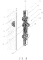
engagement portion 96 is also attached to an elongaterectangular portion 108 having aslot 110. Referring toFigures 17 to 19 , alocking mechanism 62 is shown comprising anangled tab 112 which abuts awall 114 of theaperture 60 at thefirst end 94 of the aperture to stop thelocking mechanism 62 from travelling further upwards along theaperture 60, thereby preventing thelocking mechanism 62 from falling out of theaperture 60. Theangled tab 112 is moveably attached to thelocking mechanism 62 so that theangled tab 112 can be pushed into theslot 110 of theelongate portion 108 by a user or suitable tool for removal of thelocking mechanism 62 from the aperture. A similar tab is installed within theother locking mechanism 62. - Referring to
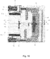
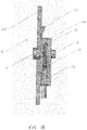
Figures 17 and18 in particular, biasing means in the form of aspring 116 is shown installed in acavity 118 of alocking mechanism 62. Thecavity 118 is shown formed within the slidingportion 104 of thelocking mechanism 62. Thespring 116 is installed between an end of thecavity 118 and aplunger 120. Thespring 116 biases thelocking mechanism 62 upwards towards thefirst end 94 of theaperture 60. Thespring 116 is compressed toward theplunger 120 by downward motion of thelocking mechanism 62 relative to thevoltage distribution unit 12. A similar spring (not shown) is installed within the other locking mechanism 62 (seeFigure 14 ). - Referring in particular to
Figures 11 and12 , as theramps 56 approach the lockingmechanisms 62, theramps 56 engages the first side surfaces 98 of theengagement portions 96. This causes the lockingmechanisms 62 to slide downward from first ends 94 in theapertures 60 towards second ends 106 against the action of thesprings 116. As thecurrent management device 10 is pushed further into thecompartment 16, the second side surfaces 102 eventually pass the flat faces 58 of theramps 56 and the lockingmechanisms 62 become free to slide upwards along theapertures 60 back towards the first ends 94. This results in the second side surfaces 102 being located adjacent the flat faces 58 such that, if thecurrent management device 10 is subsequently pulled backward, the flat faces 58 abut the second side surfaces 102 of theengagement portions 96 to prevent thecurrent management device 10 from being removed from thecompartment 16. As described above, theramps 56 andflat faces 58 constitute an embodiment of a locking mechanism of thecurrent management device 10. The locking mechanism of thecurrent management device 10 interacts with thelocking mechanism 62 of the voltage distribution unit to bring the unit and the device into a locked configuration as thedevice 10 is slid into the voltage distribution unit, without requiring an installer to manipulate the locking mechanisms themselves. Thecurrent management device 10 is thereby installed in the voltage distribution unit in a locked configuration. In the locked configuration, the current management device is prevented from being ejected or otherwise withdrawn from the voltage distribution unit.Figure 12 shows a close-up view of the locked configuration. - Referring to
Figures 1 to 5 and10 to 19 , the action of thelevers 22 will now be described. - The
levers 22 act to move the lockingmechanisms 62 along theapertures 60 against the action of thesprings 116 to unlock thecurrent management device 10 from thecompartment 16. When thecurrent management device 10 is in the locked configuration, portions ofarms 26 of thelevers 22 are located abovetop surfaces 98 of theengagement portions 96. Lifting of thehandles 28 of thelevers 22, that is application of a moment of thelevers 22 about pivot points 24, causes thearms 26 to push downward on thetop surfaces 98 of theengagement portions 96 against the action of thesprings 116. With reference toFigure 3 , for the sake of example, the moment is anticlockwise about thepivot point 24 shown. - The applied moment causes the
arms 26 to push the lockingmechanisms 62 downward along the channels defined by theapertures 60 until the second side surfaces 102 of theengagement portions 96 clear the flat faces 58 of theramps 56. Once the second side surfaces 102 clear the flat faces 58, theengagement portions 96 of the lockingmechanisms 62 no longer abut the flat faces 56 of thehousing 14 to prevent egress of thecurrent management device 10 from thecompartment 16, so thecurrent management device 10 is now in an unlocked configuration and can be pulled out of thecompartment 16. - As the
current management device 10 is withdrawn, the lockingmechanisms 62 slide down theramps 56 without hindering the egress of thecurrent management device 10 and the lockingmechanisms 62 return to the first ends 94 of theirrespective apertures 60 ready for a subsequent installation if desired. - Accordingly, there have been described a current management device for use with a voltage distribution unit, comprising: blades for engaging corresponding plates of the voltage distribution unit; and bars configured to slide along corresponding shelves of the voltage distribution unit to support the current management device and guide the blades of the current management device and plates of the voltage distribution unit into mutual engagement during insertion of the current management device into the voltage distribution unit, a voltage distribution unit comprising plates for engaging blades of a current management device; shelves configured to slidably receive bars of the current management device to support the current management device and guide the plates of the voltage distribution unit and blades of the current management device into mutual engagement during insertion of the current management device into the voltage distribution unit, and a system comprising the current management device installed in the voltage distribution unit.
- Although particular embodiments of this disclosure have been described, it will be appreciated that many modifications/additions and/or substitutions may be made within the scope of the claims.
Claims (15)
- A current management device for use with a voltage distribution unit, comprising:a plurality of electrical contacts for engaging corresponding electrical contacts of the voltage distribution unit;at least two support members configured to slide along corresponding support members of the voltage distribution unit to support the current management device and guide the electrical contacts of the current management device and voltage distribution unit into mutual engagement during insertion of the current management device into the voltage distribution unit; andat least one locking mechanism for engaging a respective at least one locking mechanism of the voltage distribution unit, the at least one locking mechanism being configured to move the respective at least one locking mechanism of the voltage distribution unit into a locking configuration as the support members slide along the corresponding support members,wherein the at least one locking mechanism is further configured to maintain the plurality of electrical contacts in electrical connection with the corresponding electrical contacts of the voltage distribution unit while in the locking configuration.
- The current management device of claim 1, comprising an enclosure, wherein at least two support members are arranged on opposite exterior faces of the enclosure.
- The current management device of claim 1 or claim 2, wherein at least one support member of the current management device comprises a support member abutment for abutting at least one support member of the voltage distribution unit to prevent egress of the current management device from the voltage distribution unit.
- The current management device of any preceding claim, further comprising at least one abutment for engaging at least one respective locking mechanism of the voltage distribution unit in a locked configuration to prevent egress of the current management device from the voltage distribution unit.
- The current management device of claim 4, wherein a surface of the at least one abutment is oriented substantially perpendicular to at least one support member of the current management device.
- The current management device of claim 4 or claim 5, further comprising at least one ramp for guiding at least one respective locking mechanism into the locked configuration.
- The current management device of claim 6, wherein at least one ramp comprises at least one abutment and defines a corner between the ramp and the abutment.
- The current management device of any one of claims 4 to 7, further comprising at least one lever pivotably attached to the current management device for engaging at least one of said respective locking mechanisms of the voltage distribution unit to cause the at least one locking mechanism to move out of the locked configuration and into an unlocked configuration, thereby enabling removal of the current management device from the voltage distribution unit.
- A voltage distribution unit, comprising:a plurality of electrical contacts for engaging corresponding electrical contacts of a current management device;at least two support members configured to slidably receive corresponding support members of the current management device to support the current management device and guide the electrical contacts of the voltage distribution unit and current management device into mutual engagement during insertion of the current management device into the voltage distribution unit; andat least one locking mechanism for engaging a respective at least one locking mechanism of the current management device, the at least one locking mechanism being configured to be moved by the respective at least one locking mechanism of the current management device into a locking configuration as the support members of the current management device slide along the support members of the voltage distribution unit,wherein the at least one locking mechanism is further configured to maintain the plurality of electrical contacts in electrical connection with the corresponding electrical contacts of the current management device while in the locking configuration.
- The voltage distribution unit of claim 9, wherein the at least two support members of the voltage distribution unit are arranged on opposite interior faces of the voltage distribution unit.
- The voltage distribution unit of claim 9 or claim 10, further comprising at least one aperture wherein at least one locking mechanism is slidable along at least one said aperture, the at least one locking mechanism comprising a first surface for engaging a ramp of the current management device to cause the locking mechanism to slide along the aperture, and a second surface for engaging the current management device in a locked configuration.
- The voltage distribution unit of claim 11, wherein the at least one locking mechanism comprises a top surface for engaging a respective lever of the current management device, such that action of the lever on the top surface causes the at least one locking mechanism to move along at least one respective aperture to move the at least one locking mechanism into an unlocked configuration.
- The voltage distribution unit of claim 11 or claim 12, wherein the second surface is configured to abut an abutment of the current management device in the locked configuration to prevent egress of the current management device from the voltage distribution unit.
- The voltage distribution unit of any one of claims 9 to 13, further comprising biasing means for biasing at least one locking mechanism toward a first position.
- A system comprising a current management device according to any of claims 1 to 8 and a voltage distribution unit according to any one of claims 9 to 14.
Applications Claiming Priority (1)
| Application Number | Priority Date | Filing Date | Title |
|---|---|---|---|
| GBGB1911565.8A GB201911565D0 (en) | 2019-08-13 | 2019-08-13 | Current management device and voltage distribution unit |
Publications (1)
| Publication Number | Publication Date |
|---|---|
| EP3780062A1 true EP3780062A1 (en) | 2021-02-17 |
Family
ID=67991054
Family Applications (1)
| Application Number | Title | Priority Date | Filing Date |
|---|---|---|---|
| EP20186435.2A Pending EP3780062A1 (en) | 2019-08-13 | 2020-07-17 | Current management device and voltage distribution unit |
Country Status (3)
| Country | Link |
|---|---|
| EP (1) | EP3780062A1 (en) |
| AU (1) | AU2020217305B2 (en) |
| GB (1) | GB201911565D0 (en) |
Citations (3)
| Publication number | Priority date | Publication date | Assignee | Title |
|---|---|---|---|---|
| GB2486612A (en) * | 2012-03-23 | 2012-06-20 | Lucy & Company Ltd W | Fuse holder |
| WO2016042290A1 (en) | 2014-09-15 | 2016-03-24 | Schneider Electric Limited | Current management device |
| WO2020109640A1 (en) * | 2018-11-29 | 2020-06-04 | Ormazabal Corporate Technology, A.I.E. | Switching and protection means for low-voltage switchboard and low-voltage switchboard incorporating said switching and protection means |
-
2019
- 2019-08-13 GB GBGB1911565.8A patent/GB201911565D0/en not_active Ceased
-
2020
- 2020-07-17 EP EP20186435.2A patent/EP3780062A1/en active Pending
- 2020-08-10 AU AU2020217305A patent/AU2020217305B2/en active Active
Patent Citations (3)
| Publication number | Priority date | Publication date | Assignee | Title |
|---|---|---|---|---|
| GB2486612A (en) * | 2012-03-23 | 2012-06-20 | Lucy & Company Ltd W | Fuse holder |
| WO2016042290A1 (en) | 2014-09-15 | 2016-03-24 | Schneider Electric Limited | Current management device |
| WO2020109640A1 (en) * | 2018-11-29 | 2020-06-04 | Ormazabal Corporate Technology, A.I.E. | Switching and protection means for low-voltage switchboard and low-voltage switchboard incorporating said switching and protection means |
Also Published As
| Publication number | Publication date |
|---|---|
| GB201911565D0 (en) | 2019-09-25 |
| AU2020217305B2 (en) | 2026-01-15 |
| AU2020217305A1 (en) | 2021-03-04 |
Similar Documents
| Publication | Publication Date | Title |
|---|---|---|
| CN109155472B (en) | Bus system | |
| US7643306B2 (en) | Apparatus for inserting and ejecting an electronic enclosure within a cabinet | |
| US9466965B2 (en) | Motor control center unit withdraw with door closed | |
| CN113470996A (en) | Locking hangtag assembly and system and method of use | |
| EP3035469A1 (en) | Recessed movable jaws for connecting a plug-in unit to a busway | |
| EP2878055B1 (en) | Improvements in or relating to electrical distribution boards | |
| US10840689B2 (en) | Universal tap-off box with a latch mechanism | |
| CN104916976B (en) | Plug-in device combination | |
| US7586052B2 (en) | Electromechanical switching device | |
| EP3090472B1 (en) | Electrical circuit breaker assembly | |
| AU2020217305B2 (en) | Current management device and voltage distribution unit | |
| CN109818220B (en) | Electrical system comprising an electrical unit and an interchangeable connection module | |
| HK40035950A (en) | Current management device and voltage distribution unit | |
| AU628535B2 (en) | Locking handle for printed circuit board assemblies | |
| US9698529B1 (en) | Cable holder for system serviceabilty | |
| CN104916979B (en) | Plug-in device combination | |
| US20110217857A1 (en) | Cradle for fastening a terminal block to a mounting frame and arrangement for earthing a terminal block | |
| US4631638A (en) | Box for holding circuit boards | |
| JP2012182301A (en) | Electronic circuit unit and electronic apparatus | |
| CN101582565B (en) | Apparatus and method for electrical system enclosure | |
| EP1524889B1 (en) | Fastening device of replaceable terminal or electronic modules with integrated quick disconnnecting system | |
| GB2551421B (en) | Safety system | |
| CN214203993U (en) | Cut terminal device with locking device | |
| EP0935323B1 (en) | An adaptor with a protected contact for connecting electrical devices to distribution bars | |
| CN121488376A (en) | Interlocking manual barriers to reduce the risk of electric shock |
Legal Events
| Date | Code | Title | Description |
|---|---|---|---|
| PUAI | Public reference made under article 153(3) epc to a published international application that has entered the european phase |
Free format text: ORIGINAL CODE: 0009012 |
|
| STAA | Information on the status of an ep patent application or granted ep patent |
Free format text: STATUS: THE APPLICATION HAS BEEN PUBLISHED |
|
| AK | Designated contracting states |
Kind code of ref document: A1 Designated state(s): AL AT BE BG CH CY CZ DE DK EE ES FI FR GB GR HR HU IE IS IT LI LT LU LV MC MK MT NL NO PL PT RO RS SE SI SK SM TR |
|
| AX | Request for extension of the european patent |
Extension state: BA ME |
|
| STAA | Information on the status of an ep patent application or granted ep patent |
Free format text: STATUS: REQUEST FOR EXAMINATION WAS MADE |
|
| 17P | Request for examination filed |
Effective date: 20210310 |
|
| RBV | Designated contracting states (corrected) |
Designated state(s): AL AT BE BG CH CY CZ DE DK EE ES FI FR GB GR HR HU IE IS IT LI LT LU LV MC MK MT NL NO PL PT RO RS SE SI SK SM TR |
|
| REG | Reference to a national code |
Ref country code: HK Ref legal event code: DE Ref document number: 40035950 Country of ref document: HK |
|
| STAA | Information on the status of an ep patent application or granted ep patent |
Free format text: STATUS: EXAMINATION IS IN PROGRESS |
|
| 17Q | First examination report despatched |
Effective date: 20240315 |