EP3780057A1 - Coil-type axial magnetic field contact assembly for vacuum interrupter - Google Patents
Coil-type axial magnetic field contact assembly for vacuum interrupter Download PDFInfo
- Publication number
- EP3780057A1 EP3780057A1 EP20190593.2A EP20190593A EP3780057A1 EP 3780057 A1 EP3780057 A1 EP 3780057A1 EP 20190593 A EP20190593 A EP 20190593A EP 3780057 A1 EP3780057 A1 EP 3780057A1
- Authority
- EP
- European Patent Office
- Prior art keywords
- electrode assembly
- support member
- arcuate
- electrode
- arcuate arm
- Prior art date
- Legal status (The legal status is an assumption and is not a legal conclusion. Google has not performed a legal analysis and makes no representation as to the accuracy of the status listed.)
- Granted
Links
Images


Classifications
-
- H—ELECTRICITY
- H01—ELECTRIC ELEMENTS
- H01H—ELECTRIC SWITCHES; RELAYS; SELECTORS; EMERGENCY PROTECTIVE DEVICES
- H01H33/00—High-tension or heavy-current switches with arc-extinguishing or arc-preventing means
- H01H33/60—Switches wherein the means for extinguishing or preventing the arc do not include separate means for obtaining or increasing flow of arc-extinguishing fluid
- H01H33/66—Vacuum switches
- H01H33/664—Contacts; Arc-extinguishing means, e.g. arcing rings
- H01H33/6642—Contacts; Arc-extinguishing means, e.g. arcing rings having cup-shaped contacts, the cylindrical wall of which being provided with inclined slits to form a coil
-
- H—ELECTRICITY
- H01—ELECTRIC ELEMENTS
- H01H—ELECTRIC SWITCHES; RELAYS; SELECTORS; EMERGENCY PROTECTIVE DEVICES
- H01H33/00—High-tension or heavy-current switches with arc-extinguishing or arc-preventing means
- H01H33/60—Switches wherein the means for extinguishing or preventing the arc do not include separate means for obtaining or increasing flow of arc-extinguishing fluid
- H01H33/66—Vacuum switches
- H01H33/664—Contacts; Arc-extinguishing means, e.g. arcing rings
- H01H33/6643—Contacts; Arc-extinguishing means, e.g. arcing rings having disc-shaped contacts subdivided in petal-like segments, e.g. by helical grooves
-
- H—ELECTRICITY
- H01—ELECTRIC ELEMENTS
- H01H—ELECTRIC SWITCHES; RELAYS; SELECTORS; EMERGENCY PROTECTIVE DEVICES
- H01H33/00—High-tension or heavy-current switches with arc-extinguishing or arc-preventing means
- H01H33/60—Switches wherein the means for extinguishing or preventing the arc do not include separate means for obtaining or increasing flow of arc-extinguishing fluid
- H01H33/66—Vacuum switches
- H01H33/664—Contacts; Arc-extinguishing means, e.g. arcing rings
- H01H33/6641—Contacts; Arc-extinguishing means, e.g. arcing rings making use of a separate coil
-
- H—ELECTRICITY
- H01—ELECTRIC ELEMENTS
- H01H—ELECTRIC SWITCHES; RELAYS; SELECTORS; EMERGENCY PROTECTIVE DEVICES
- H01H33/00—High-tension or heavy-current switches with arc-extinguishing or arc-preventing means
- H01H33/60—Switches wherein the means for extinguishing or preventing the arc do not include separate means for obtaining or increasing flow of arc-extinguishing fluid
- H01H33/66—Vacuum switches
- H01H33/664—Contacts; Arc-extinguishing means, e.g. arcing rings
- H01H33/6644—Contacts; Arc-extinguishing means, e.g. arcing rings having coil-like electrical connections between contact rod and the proper contact
-
- H—ELECTRICITY
- H01—ELECTRIC ELEMENTS
- H01H—ELECTRIC SWITCHES; RELAYS; SELECTORS; EMERGENCY PROTECTIVE DEVICES
- H01H33/00—High-tension or heavy-current switches with arc-extinguishing or arc-preventing means
- H01H33/60—Switches wherein the means for extinguishing or preventing the arc do not include separate means for obtaining or increasing flow of arc-extinguishing fluid
- H01H33/66—Vacuum switches
- H01H33/664—Contacts; Arc-extinguishing means, e.g. arcing rings
- H01H2033/6648—Contacts containing flexible parts, e.g. to improve contact pressure
-
- H—ELECTRICITY
- H01—ELECTRIC ELEMENTS
- H01H—ELECTRIC SWITCHES; RELAYS; SELECTORS; EMERGENCY PROTECTIVE DEVICES
- H01H2211/00—Spacers
- H01H2211/006—Individual areas
-
- H—ELECTRICITY
- H01—ELECTRIC ELEMENTS
- H01H—ELECTRIC SWITCHES; RELAYS; SELECTORS; EMERGENCY PROTECTIVE DEVICES
- H01H2227/00—Dimensions; Characteristics
- H01H2227/024—Spacer elements
Definitions
- This patent document relates to vacuum interrupters, and more particularly relates to improved axial magnetic field coils for vacuum interrupters.
- Vacuum interrupters are typically used to interrupt electrical current flows.
- the interrupters include a generally cylindrical vacuum envelope surrounding a pair of coaxially aligned separable electrode assemblies having opposing contact surfaces. The contact surfaces abut one another in a closed circuit position and are separated to open the circuit.
- Each electrode assembly is connected to a current carrying terminal post extending outside the vacuum envelope and connecting to an electrical circuit.
- An arc is typically formed between the contact surfaces when the contacts are moved apart to the open circuit position while carrying current. The arcing continues until the current is interrupted. Metal from the contacts that is vaporized by the arc forms a plasma during arcing and condenses back onto the contacts and also onto vapor shields placed between the electrode assemblies and the vacuum envelope after the current is extinguished.
- the arc generally is initially in a constricted, columnar form that creates a thermal plasma.
- a thermal plasma has very high temperature and can support a significant current between the contacts, and therefore make the current more difficult to interrupt. It is advantageous to encourage the columnar arc to become a diffuse arc, leading to a lower temperature plasma and easier interruption at current zero.
- a diffuse arc because it distributes the arc energy over a broader area of the contact surface, does not vaporize as much of the contact as does a columnar arc, and thereby extends the useful life of the contacts and the interrupter.
- Axial Magnetic Field Axial Magnetic Field
- the field can be self-generated by the current in coils located behind each contact.
- a variety of electrode assemblies incorporating such coils for axial magnetic field vacuum interrupters are discussed in the article entitled " The Vacuum Interrupter Contact” by Paul Slade, IEEE Trans. on Components, Hybrids, and Mfg. Tech., Vol. 7, No. 1, March 1984 .
- Prior art coils such as the coils disclosed in U.S. Patent Nos. 4,260,864 , 4,588,879 and 5,055,639 , herein incorporated by reference, typically include current carrying arms radiating from a central hub, the radial arms connecting to arcuate coil elements.
- Some axial magnetic field vacuum interrupter designs such as those disclosed in U.S. Patent Nos. 4,675,483 , 4,871,888 , 4,982,059 and 5,313,030 , herein incorporated by reference, have attempted to reduce or eliminate the radially extending portions of the coils by using cylindrical coils having a plurality of angled slots, the angled slots defining a plurality of helically extending current carrying arms.
- axial magnetic field vacuum interrupters such as those disclosed in U.S. Patent Nos. 3,823,287 , 4,704,506 and 5,777,287 , herein incorporated by reference, incorporate cylindrical coils which are spaced axially forward of a backing plate.
- the azimuthal length of the arm is less than half a circle (i.e., 180°).
- the length of the arcuate coil arm is increased to increase the self-generated AMF by the circular current flow along these arms.
- a coil design may have an arm length about 2/3 of a circle (i.e., 240°), an arm length of 3 ⁇ 4 of a circle (i.e., 270°), or a coil where the current is caused to flow a full circle (i.e., 360°) to generate a maximal AMF
- the contacts of the electrode assemblies may be violently slammed together (i.e., under compression during a closing operation) to reconnect the circuit.
- one or more small welds may form at the contacts interface between the movable contact and the fixed contact.
- the circuit breaker must be able to break those small welds to separate the pair of contacts in order to interrupt the current of the circuit.
- the coil experiences a tensile load (i.e., under tension during an opening operation). The coil must be able to withstand this tensile load without plastic deformation, that is, without its arms being pulled apart.
- the spaced coil arm can withstand the large tensile and compressive forces (e.g., stress forces) generated during these interruptions, but during critical events the forces are too large and change the shape of the coils (i.e., the arms of the coils become deformed).
- the coil arms may be pulled apart during the occurrence of large tensile forces or may be smashed together during the occurrence of large compressive forces. Deformed coils may impair and/or void the performance of the vacuum interrupter requiring costly replacements and lengthy service interruptions as the coils are permanently sealed inside the vacuum envelope.
- Electrode assemblies employed for higher voltage ratings also require longer coil arms, which are more prone to damage when compared to electrode assemblies for lower voltage ratings.
- an electrode assembly for a vacuum interrupter includes a contact plate, an electrode coil, and at least one support member.
- the electrode coil includes a base for attachment to a terminal post of the vacuum interrupter, and at least one arcuate arm between the base and the contact plate extending along a curved path in a plane substantially perpendicular to a direction of travel of the electrode assembly.
- the electrode coil may be connected to the contact plate at or near the end of its arm or arms, or otherwise as described below.
- each arcuate arm includes an end surface that includes an aperture that is positioned to align with a corresponding aperture of an adjacent end surface of an adjacent arcuate arm.
- Each of the support members are partially positioned within aligned apertures to maintain a gap between adjacent end surfaces.
- the apertures may be placed near the ends of the arcuate arm, and they may be positioned to hold a support pin that will maintain a gap between a lower surface of one arm and an upper surface of another arm, or between an arm and the contact plate or base of the electrode assembly.
- a filler material may be at least partially included with the aperture(s) to mechanically and electrically connect each support member and/or arcuate arm to the contact plate.
- each support member may be a hollow pin and a portion of each aperture may be filled with the filler material.
- the filler material may be a brazing material joining the support member and the arcuate arm to the electrode coil and the contact plate.
- the gap may have an angle of about 15 degrees to about 75 degrees with respect to the plane.
- the gap has an angle of about 30 degrees with respect to the plane.
- the gap may have an angle of 90 degrees with respect to the plane.
- each arcuate arm may include an extension member connecting the arcuate arm to the base.
- the base may be generally disk-shaped, and each extension member may extend from its arcuate arm in a direction substantially perpendicular to the plane. All of the arcuate arms may collectively have an outer radius substantially equal to an outer radius of the generally disk-shaped base.
- each arcuate arm may include a raised portion connecting each arcuate arm to the contact plate.
- the contact plate may be generally disk-shaped, and the raised portion of each arcuate arm may extend in a direction substantially perpendicular to the plane. All of the arcuate arms may collectively have an outer radius substantially equal to an outer radius of the generally disk-shaped contact plate.
- the electrode coil may include three arcuate arms, and each of the arcuate arms may extend almost 120° around a circumference of the electrode assembly.
- the at least one arcuate arm may have a substantially uniform radius of curvature.
- the electrode assembly may further include an inner support and a lower support.
- the inner support may be attached between the contact plate and the base of the electrode coil, and may be positioned interior of the at least one arcuate arm.
- the lower support may be attached to the base of the electrode coil.
- the base of the electrode coil may include at least one slot
- the lower support may include at least one slot
- the at least one slot of the lower support may be positioned adjacent the at least one slot of the base.
- the support member may be a pin, may include longitudinal slot, may be hollow, and/or may be made of a material of a lower electrical conductivity than that of the material of the coil arm.
- the support member may comprise materials such as steel, nickel chromium alloys (e.g., Nichrome) and titanium alloys, or even an insulating material, such as a ceramic.
- each aperture may be located either on the raised portion of the arcuate arm, on the non-raised portion of the arcuate arm, or on both.
- each arcuate arm may include at least one additional aperture positioned to align with a corresponding aperture of either an adjacent end surface of the adjacent arcuate arm or on the base.
- first component may be an “upper” component and a second component may be a “lower” component when a device of which the components are a part is oriented in a first direction.
- the relative orientations of the components may be reversed, or the components may be on the same plane, if the orientation of the structure that contains the components is changed.
- the drawings are not to scale. The claims are intended to include all orientations of a device containing such components.
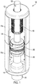
- a vacuum interrupter 100 includes first and second electrode assemblies 300 and 302, first and second terminal posts 120 and 122, and a vacuum envelope 110.
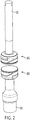
- FIG. 2 is a partial view of the current carrying portion of the vacuum interrupter 100 of FIG. 1 with the vacuum envelope 110 removed.
- the vacuum envelope 110 includes spaced end caps 112 and 114 joined by one or more tubular insulating casings 116a, 116b.
- a vapor shield 118 may be included in the vacuum envelope 110 and may be either electrically isolated from the electrode assemblies 300 and 302 or connected to only one of the electrode assemblies 300 and 302. It protects the insulating surface of the insulating casings 116a, 116b from being degraded by the metal vapors generated during a circuit interruption event.
- the vacuum envelope 110 surrounds both electrode assemblies 300 and 302 to form the capsule of the vacuum.
- First and second terminal posts 120 and 122 are electrically coupled to the first and second electrode assemblies 300 and 302, respectively, for coupling the first and second electrode assemblies 300 and 302 to an electrical circuit.
- a mechanism such as a bellows assembly 130, permits axial movement of at least one of the electrode assemblies 300 and 302 between a closed circuit position ( FIG. 1 ) and an open circuit position ( FIG. 2 ) while maintaining the vacuum seal of the vacuum envelope 110.
- the first and second electrode assemblies 300 and 302 and the first and second terminal posts 120 and 122 define a common longitudinal axis for the vacuum interrupter 100.
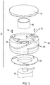
- FIG. 3 is an exploded view of the components of an electrode assembly 300 and a partial view of a terminal post 120 upon which it is connected.
- the electrode assembly 300 includes a contact plate 400, an inner support 800, a generally cup-shaped electrode coil 500 having three arcuate arms 530 (as will be described in more detail below), a lower support 600, and three support members 700 positioned between (and optionally partially in) the arcuate arms 530 (as will be described in more detail below).
- each electrode assembly 300, 302 of FIGS. 1 and 2 may have a structure such as shown in FIGS. 3 to 11 .
- the reference to items as being “top” and “bottom,” “above” and “below,” “atop” and “under,” “upper” and “lower,” or “front” and “rear,” is only intended to be relative and to reflect the orientation shown in FIG. 3 .
- a similar electrode assembly 302 would necessarily be inverted as compared to the assembly for electrode assembly 300. Or, the electrode assemblies may be aligned either tilted or sideways on a horizontal plane.
- the contact plate 400, electrode coil 500, and terminal posts 120 and 122 are all made from materials having high electrical conductivity for electric current flow, whereas the lower support 600, support members 700, and inner support 800 are all made from materials having high electrical resistivity to electric current flow. This allows the current to pass along the electrode assemblies 300 and 302 with little to no effect of the support devices 600, 700, 800 from interfering with the desired circular flow generatoring the axial magnetic field within the vacuum envelope 110.
- the contact plate 400 may be made from copper-chromium (Cu-Cr) alloys
- the electrode coil 500, and terminal post 120 may be made from Oxygen-free copper (OFC), CuCr alloys, or other suitable materials
- the lower support 600, support members 700, and inner support 800 may be made from stainless steel, ceramic, or other suitable materials.
- nickel chromium alloys (e.g., Nichrome) and titanium alloys are suitable support materials with high electrical resistivity (as compared to the resistivity of the electrode arms), low vapor pressures, and high melting points compatible with vacuum brazing.
- FIGS. 4A-4D are top, side, bottom, and isometric views respectively of a contact plate 400 in accordance with various embodiments.
- the contact plate 400 includes an outer surface 402 and an inner surface 404.
- the contact plate 400 may be attached to the inner support 800 by any suitable structure, such as a raised portion 406 on the inner surface 404 which fits inside or around the inner support 800.
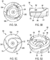
- FIGS. 5A-5D are top, side, bottom, and isometric views respectively of an electrode coil 500 in accordance with various embodiments.
- the electrode coil 500 may have a base 510 and at least two arcuate arms 530.
- the electrode coil 500 may have three arcuate arms 530A, 530B, and 530C (hereinafter 530 unless distinctly one or the other), each of which has a substantially uniform radius of curvature and extends almost 120° around the circumference of the coil to provide a circumferential current path. While three arcuate arms are shown, it is to be understood that any suitable number of arcuate arms may be used.
- a single arcuate arm extending almost 360° around the circumference of the coil may be used.
- two, four, or more arcuate arms may be used, provided that the arms together extend around the circumference in one or more rings (for example, in a stacked or spiral structure), and are capable of generating a sufficient axial magnetic field during operation of the electrode coil.
- the arcuate arm 530 may extend along a curved path in a plane substantially perpendicular to a direction of travel of the electrode assembly.
- the arcuate arms shown in FIGS. 5A-5D have a substantially uniform radius of curvature with respect to the center of the coil, other configurations such as spiral arms may be used.
- the base 510 and arcuate arms 530 may be fabricated from a single piece of material.
- the material of these components may be any material having sufficient electrical conductivity and heat transfer capability. Metals such as copper and Cu/Cr composites are suitable.
- the base 510 is generally disk shaped having an inner surface 512 and an outer surface 514.
- the inner surface 512 may include a circular indentation 516 for receiving the inner support 800, as will be described in more detail below.
- the outer surface 514 may include a circular raised portion 518 for receiving the lower support ( 600 of FIG. 3 ), as will be described in more detail below.
- the base 510 may include an aperture 520 for receiving a protrusion ( 124 of FIG. 3 ) on an end of a terminal post 120 by any connection methods, such as welding, brazing, soldering, press fitting (e.g., interference fitting), or other connection methods.
- the aperture 520 may pass through the center of the base 510 which prevents gas entrapment.
- the base 510 may include slots 522 forming radial extensions 524. For example, as illustrated in FIG. 5C , the base 510 may have three radial extensions 524A, 524B, and 524C.
- each arcuate arm 530 may include an extension member 532 that extends from the arcuate arm 530 and that connects the arcuate arm 530 to the base 510, and a raised portion 536 for connecting to inner surface 404 of the contact plate 400.
- Each arcuate arm 530 includes an inner surface 538, an outer surface 540, an upper surface 542, a lower surface 544, a first end surface 546, and second end surface 548. The first end surface 546 of one arcuate arm 530 may face the second end surface 548 of an adjacent arcuate arm 530 forming a gap G.
- the arcuate arms 530 nearly form a complete circle around the circumference of the electrode coil 500 with only minor gaps G between the first and second end surfaces 546, 548 of each arcuate arm 530.
- the gaps G between each of the end surfaces 546, 548 may extend along the longitudinal direction of the vacuum interrupter 100 (i.e. having a right angle) or may be radially slanted in a range of about 10° to almost 90°, a range of about 15° to about 60°, a range of about 20° to about 45°, or a range of about 25° to about 35°.
- the gaps G between each of the end surfaces 546, 548 is slanted approximately 30°.
- the gaps G between each of the end surfaces 546', 548' are not slanted.
- each arcuate arm 530 may include an extension member 532 that extends from the lower surface 544 of the arcuate arm 530 and that connected the arcuate arm 530 to the base 510.
- the upper surface 542 of one level faces the contact plate, while the lower surface 544 of a different level faces the base 510.
- These two levels may be adjacent to each other, or additional levels may be between them.
- At least a portion of end surfaces of all arcuate arms partially faces an end surface of another arcuate arm.
- the gap G (e.g., distance) between these two end surfaces are maintained by the support member 700, as will be described in more details below.
- Each arcuate arm 530 includes at least one aperture 550, 552 extending into one or both of its end surfaces 546 or 548.
- the aperture may extend through the arcuate arm 530 to the corresponding upper surface 542 or lower surface 544 (e.g., as a through bore), or it may extend only partially into the arcuate arm 530 as a recess.
- Each aperture 552 may be aligned with a corresponding aperture 550 of an adjacent arcuate arm 530 (or with an aperture on the arcuate arm's other end if only one arcuate arm is used).
- the apertures 550, 552 may be formed by any suitable method such as, for example, by drilling. As shown in FIGS.
- the apertures 550, 552 may be formed parallel to the longitudinal axis of the vacuum interrupter 100 or, alternatively, the apertures 550, 552 may be formed at a non-parallel angle.
- the apertures 550, 552 may be formed normal to the end surfaces 546, 548.
- the apertures 550, 552 may be formed before or after the arcuate arms 530 of electrode coil 500 are formed to their final shape.
- FIGS. 3 and 9 illustrate that portions of each support member 700 are fixed within the aperture pair 550, 552 of each pair of adjacent arcuate arms 530, as will be described in more detail below.
- the pin 700 helps to maintain the gap G between the end surfaces of adjacent arcuate arms.
- FIGS. 6A-6D are top, side, bottom, and isometric views respectively of a lower support 600 in accordance with various embodiments.
- the lower support 600 may be positioned adjacent the outer surface 514 of the electrode coil 500 to support the electrode coil 500 during vacuum interrupter operations.
- the lower support 600 includes an outer surface 602, an inner surface 604, and an aperture 606.
- the aperture 606 is sized to permit the circular raised portion 518 on the outer surface 514 of the electrode coil 500 to pass through with suitable connection methods, such as welding, brazing, soldering, press fitting (e.g., interference fitting), or other connection methods.
- the lower support 600 may optionally include at least one outwardly extending slot 608 similar in placement as the slots 522 on the base 510 of the electrode coil 500.
- the lower support 600 having slots 608 may increase the axial magnetic field by decreasing the current flowing through the supporting plate 600.
- the lower support 600 having slots 608 may be on either the first electrode assembly 300 (see FIG. 3 ), the second electrode assembly 302, or both. Likewise the lower support 600 may optionally not include slots (see the second electrode assembly 302 in FIG. 2 ).
- the support member 700 mechanically connects the free end of one arcuate arm 530 of the electrode coil 500 rigidly to another portion of the electrode coil 500 to serve as a spacer and to provide resistance to tensile forces and compressive forces during cyclic operations of the vacuum interrupter 100.
- the support member 700 may be a pin, a threaded screw, an elongated beam, or the like.
- the support member 700 may be positioned vertically into matching apertures 550, 552 on the first end surface 546 and second end surface 548 so as to mechanically connect the first end surface 546 of one arcuate arm 530 rigidly to the second end surface 548 of another arcuate arm 530.
- the support member 700 may be positioned into matching apertures 550, 552.
- the support member 700 may be a threaded screw support member positioned vertically into matching threaded apertures 550, 552.
- the support member 700 may be positioned radially between matching channels on the first end surface 546 and second end surface 548 so as to mechanically connect (e.g., interlock) the first end surface 546 of one arcuate arm 530 rigidly to the second end surface 548.
- an I-beam shaped support member 700 may be positioned radially into matching T-shaped channels on the first end surface 546 and second end surface 548.
- Each support member 700 may be made from a material which provides both resistance to tensile forces and compressive forces.
- the support members 700 made of stainless steel minimizes the long cantilevered portions of the arcuate arms from being pulled apart from the other components of the electrode coil under a tensile load and from being plastically deformed under a compression load.
- the support members 700 may also be made from material that is substantially more electrically resistive (less conductive) than the electrode arms, in order to allow the current to flow undisturbed by the support members 700.
- example materials include stainless steel, nickel chromium alloys (e.g., Nichrome), and titanium alloys.
- FIG. 7 is an isometric view of a pin-shaped support member 700 in accordance with various embodiments.
- Each support member 700 may include an outer wall 702 that is optionally cylindrical, and optionally includes tapered ends 704a, 704b to assist with insertion through the apertures ( 550, 552 in FIGS. 5D and 9 ) of each arcuate arm 530 of the electrode coil 500.
- the support member 700 may have an outer sidewall with a diameter (or other measurement of width, if non-circular) that is less than the inner diameter of the apertures 550, 552 of the arcuate arms 530 to allow the support member 700 to be placed within the apertures 550, 552.
- the support member 700 may optionally have a hollow core 708 centrally located, for example, to increase resistivity of the support member's entire volume.
- the support member 700 may also have a longitudinal slot 706 that extends from one end 704a of the sidewall to the other end 704b of the sidewall and that is aligned with the axial direction of the vacuum interrupter 100 to minimize eddy current induced in the support member 700 itself.
- FIG. 8 is an isometric view of an inner support 800 that may be included in some embodiments.
- the inner support 800 fits within the circular indentation 516 in the base 510 of the electrode coil 500 (see FIG. 5A ).
- a hole 802 may be provided through the inner support 800 in order to prevent gas from being trapped in the inner support 800.
- the contact plate 400 is attached to the inner support 800 by the circular raised portion 406 which fits inside the inner support 800.
- FIG. 9 is a sectional view along one support member 700 positioned within an electrode coil 500 in accordance with various embodiments.
- the support member 700 may be positioned with an aperture 550 of a first arcuate arm 530B and then abutting into a matching aperture 552 in a second arcuate arm 530A.
- the remaining void may be filled with a filler material.
- a brazing element 554 having a pre-form of a T-shape matching the initial void to properly and solidly join the support member 700 to first arcuate arm 530A, second arcuate arm 530B, and contact plate 400.
- the T-shaped brazing element 554 may be placed within the hollow portion 708 of the support member 700 within the apertures 550, 552 such that an upper surface of the brazing element 554 extends above the raised portion 536 of the arcuate arm 530.
- the contact plate 400 may be placed against the upper surfaces of the brazing elements 554 and the raised portions 536 of the arcuate arms 530 and then heated to the brazing temperature. During this brazing process, the brazing elements 554 is heated to a molten form and allowed to conform to the adjacent surfaces during cooling, thus connecting the contact plate 400 to the arcuate arms 530 and the support members 700. This connection improves the ability of the electrode coil 500 from withstanding tensile forces during opening operations while strengthening the arcuate arms 530 of the electrode coil 500 to withstand compressive forces during closing operations.
- FIG. 10 is an isometric view of an alternate electrode coil 500' in accordance with another embodiment.
- Each arcuate arm 530' of the electrode coil 500' may have an extension member 532' extending from the arcuate arm 530' in a longitudinal direction (i.e., parallel with the longitudinal direction of the vacuum interrupter 100 ) and connecting the arcuate arm 530' to the base 510'.
- the gap G between the end surfaces 546', 548' of adjacent arcuate arms 530' has a vertical axis (i.e., it is parallel to the path of travel of the interrupter when activated),
- the aperture 550' on one of the arcuate arms 530' may align with a corresponding aperture 552' located on the base 510'.
- FIG. 11 is an isometric view of another electrode coil 500" similar to FIG. 10 in accordance with another embodiment.
- the electrode coil 500" may have more than one aperture 550" in each arcuate arm 530", positioned to align with matching apertures 552" located on the base 510.
- the electrode coil 500" shown in FIG. 11 includes five apertures 550" on each arcuate arm 530".
Landscapes
- High-Tension Arc-Extinguishing Switches Without Spraying Means (AREA)
Abstract
Description
- This patent document claims priority to United States Provisional Patent Application Number
62/885,571, filed August 12, 2019 - This patent document relates to vacuum interrupters, and more particularly relates to improved axial magnetic field coils for vacuum interrupters.
- Vacuum interrupters are typically used to interrupt electrical current flows. The interrupters include a generally cylindrical vacuum envelope surrounding a pair of coaxially aligned separable electrode assemblies having opposing contact surfaces. The contact surfaces abut one another in a closed circuit position and are separated to open the circuit. Each electrode assembly is connected to a current carrying terminal post extending outside the vacuum envelope and connecting to an electrical circuit.
- An arc is typically formed between the contact surfaces when the contacts are moved apart to the open circuit position while carrying current. The arcing continues until the current is interrupted. Metal from the contacts that is vaporized by the arc forms a plasma during arcing and condenses back onto the contacts and also onto vapor shields placed between the electrode assemblies and the vacuum envelope after the current is extinguished.
- The arc generally is initially in a constricted, columnar form that creates a thermal plasma. A thermal plasma has very high temperature and can support a significant current between the contacts, and therefore make the current more difficult to interrupt. It is advantageous to encourage the columnar arc to become a diffuse arc, leading to a lower temperature plasma and easier interruption at current zero. A diffuse arc, because it distributes the arc energy over a broader area of the contact surface, does not vaporize as much of the contact as does a columnar arc, and thereby extends the useful life of the contacts and the interrupter.
- One technique of encouraging formation of a diffuse arc is by imposing an Axial Magnetic Field (AMF) in the region between the contacts. The field can be self-generated by the current in coils located behind each contact. A variety of electrode assemblies incorporating such coils for axial magnetic field vacuum interrupters are discussed in the article entitled "The Vacuum Interrupter Contact" by Paul Slade, IEEE Trans. on Components, Hybrids, and Mfg. Tech., Vol. 7, No. 1, March 1984.
- Prior art coils, such as the coils disclosed in
U.S. Patent Nos. 4,260,864 ,4,588,879 and5,055,639 , herein incorporated by reference, typically include current carrying arms radiating from a central hub, the radial arms connecting to arcuate coil elements. Some axial magnetic field vacuum interrupter designs, such as those disclosed inU.S. Patent Nos. 4,675,483 ,4,871,888 ,4,982,059 and5,313,030 , herein incorporated by reference, have attempted to reduce or eliminate the radially extending portions of the coils by using cylindrical coils having a plurality of angled slots, the angled slots defining a plurality of helically extending current carrying arms. Other axial magnetic field vacuum interrupters, such as those disclosed inU.S. Patent Nos. 3,823,287 ,4,704,506 and5,777,287 , herein incorporated by reference, incorporate cylindrical coils which are spaced axially forward of a backing plate. - In all of the examples mentioned above, the azimuthal length of the arm is less than half a circle (i.e., 180°). To further increase the interruption capability of a vacuum interrupter to enable its applications into either a higher voltage and/or higher current rating, the length of the arcuate coil arm is increased to increase the self-generated AMF by the circular current flow along these arms. For example, a coil design may have an arm length about 2/3 of a circle (i.e., 240°), an arm length of ¾ of a circle (i.e., 270°), or a coil where the current is caused to flow a full circle (i.e., 360°) to generate a maximal AMF
- With the lengthening of the arm, however, the mechanical strength of the coil becomes weaker, with the long cantilever arm prone to deformation at its connection to the base (i.e., a starting point). This is further exasperated by the more and more stringent application conditions of the high voltage and high current rating. A higher voltage rating demands a larger travelling distance for the opening gap, and a faster opening speed. A higher current rating demands a larger coil diameter with a larger arm cross-section. These conditions pose a challenge on the mechanical integrity of the coil to withstand the closing and opening operations of the vacuum interrupter.
- During a closing operation of the vacuum interrupter, the contacts of the electrode assemblies may be violently slammed together (i.e., under compression during a closing operation) to reconnect the circuit. During the normal operations, one or more small welds may form at the contacts interface between the movable contact and the fixed contact. During an opening operation of the vacuum interrupter, the circuit breaker must be able to break those small welds to separate the pair of contacts in order to interrupt the current of the circuit. In this weld-breaking process, the coil experiences a tensile load (i.e., under tension during an opening operation). The coil must be able to withstand this tensile load without plastic deformation, that is, without its arms being pulled apart.
- During normal operations, the spaced coil arm can withstand the large tensile and compressive forces (e.g., stress forces) generated during these interruptions, but during critical events the forces are too large and change the shape of the coils (i.e., the arms of the coils become deformed). The coil arms may be pulled apart during the occurrence of large tensile forces or may be smashed together during the occurrence of large compressive forces. Deformed coils may impair and/or void the performance of the vacuum interrupter requiring costly replacements and lengthy service interruptions as the coils are permanently sealed inside the vacuum envelope. Electrode assemblies employed for higher voltage ratings also require longer coil arms, which are more prone to damage when compared to electrode assemblies for lower voltage ratings.
- The most common way to solve the above-noted problems is to increase the cross-sectional area of the connection of the arm to its base, thereby reducing the arm length of each coil. This has the undesired effects of lowering the axial magnetic field produced by the coil.
- It is therefore desirable to obtain an electrode assembly for a vacuum interrupter having a coil structure with supported arms which increases the useful life of the electrode assembly.
- In various embodiments, an electrode assembly for a vacuum interrupter includes a contact plate, an electrode coil, and at least one support member. The electrode coil includes a base for attachment to a terminal post of the vacuum interrupter, and at least one arcuate arm between the base and the contact plate extending along a curved path in a plane substantially perpendicular to a direction of travel of the electrode assembly. The electrode coil may be connected to the contact plate at or near the end of its arm or arms, or otherwise as described below.
- In some embodiments, each arcuate arm includes an end surface that includes an aperture that is positioned to align with a corresponding aperture of an adjacent end surface of an adjacent arcuate arm. Each of the support members are partially positioned within aligned apertures to maintain a gap between adjacent end surfaces.
- Alternatively or in addition, the apertures may be placed near the ends of the arcuate arm, and they may be positioned to hold a support pin that will maintain a gap between a lower surface of one arm and an upper surface of another arm, or between an arm and the contact plate or base of the electrode assembly.
- In some embodiments, a filler material may be at least partially included with the aperture(s) to mechanically and electrically connect each support member and/or arcuate arm to the contact plate. Optionally, each support member may be a hollow pin and a portion of each aperture may be filled with the filler material. For example, the filler material may be a brazing material joining the support member and the arcuate arm to the electrode coil and the contact plate.
- In some embodiments, the gap may have an angle of about 15 degrees to about 75 degrees with respect to the plane. For example, the gap has an angle of about 30 degrees with respect to the plane. Alternatively, the gap may have an angle of 90 degrees with respect to the plane.
- In some embodiments, each arcuate arm may include an extension member connecting the arcuate arm to the base. The base may be generally disk-shaped, and each extension member may extend from its arcuate arm in a direction substantially perpendicular to the plane. All of the arcuate arms may collectively have an outer radius substantially equal to an outer radius of the generally disk-shaped base.
- In some embodiments, each arcuate arm may include a raised portion connecting each arcuate arm to the contact plate. The contact plate may be generally disk-shaped, and the raised portion of each arcuate arm may extend in a direction substantially perpendicular to the plane. All of the arcuate arms may collectively have an outer radius substantially equal to an outer radius of the generally disk-shaped contact plate.
- In some embodiments, the electrode coil may include three arcuate arms, and each of the arcuate arms may extend almost 120° around a circumference of the electrode assembly.
- In some embodiments, the at least one arcuate arm may have a substantially uniform radius of curvature.
- In some embodiments, the electrode assembly may further include an inner support and a lower support. The inner support may be attached between the contact plate and the base of the electrode coil, and may be positioned interior of the at least one arcuate arm. The lower support may be attached to the base of the electrode coil. In some embodiments, the base of the electrode coil may include at least one slot, the lower support may include at least one slot, and the at least one slot of the lower support may be positioned adjacent the at least one slot of the base.
- In some embodiments, the support member may be a pin, may include longitudinal slot, may be hollow, and/or may be made of a material of a lower electrical conductivity than that of the material of the coil arm. For example, the support member may comprise materials such as steel, nickel chromium alloys (e.g., Nichrome) and titanium alloys, or even an insulating material, such as a ceramic.
- In some embodiments each aperture may be located either on the raised portion of the arcuate arm, on the non-raised portion of the arcuate arm, or on both.
- In another aspect of the disclosure, each arcuate arm may include at least one additional aperture positioned to align with a corresponding aperture of either an adjacent end surface of the adjacent arcuate arm or on the base.
-
-
FIG. 1 is an isometric view of an example vacuum interrupter (with a section of a vacuum envelope removed) in which an electrode coil may be installed. -
FIG. 2 is a partial view of the vacuum interrupter ofFIG. 1 with the vacuum envelope removed. -
FIG. 3 is an exploded view of example components of an electrode assembly. -
FIGS. 4A-4D are top, side, bottom, and isometric views of a contact plate. -
FIGS. 5A-5D are top, side, bottom, and isometric views of an electrode coil. -
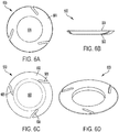
FIGS. 6A-6D are top, side, bottom, and isometric views of a lower support. -
FIG. 7 is an isometric view of a support member. -
FIG. 8 is an isometric view of an inner support. -
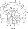
FIG. 9 is a sectional view along one support member positioned within an electrode coil. -
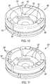
FIG. 10 is an isometric view of an alternate electrode coil. -
FIG. 11 is an isometric view of another electrode coil similar to that ofFIG. 10 . - As used in this document, the singular forms "a," "an," and "the" include plural references unless the context clearly dictates otherwise. Unless defined otherwise, all technical and scientific terms used herein have the same meanings as commonly understood by one of ordinary skill in the art. As used in this document, the term "comprising" means "including, but not limited to." When used in this document, the term "exemplary" is intended to mean "by way of example" and is not intended to indicate that a particular exemplary item is preferred or required.
- In this document, when terms such "first" and "second" are used to modify a noun, such use is simply intended to distinguish one item from another, and is not intended to require a sequential order unless specifically stated. The term "about" and "approximately," when used in connection with a numeric value, is intended to include values that are close to, but not exactly, the number. For example, in some embodiments, the term "approximately" may include values that are within +/- 10 percent of the value.
- When used in this document, terms such as "top" and "bottom," "upper" and "lower," or "front" and "rear," are not intended to have absolute orientations but are instead intended to describe relative positions of various components with respect to each other. For example, a first component may be an "upper" component and a second component may be a "lower" component when a device of which the components are a part is oriented in a first direction. The relative orientations of the components may be reversed, or the components may be on the same plane, if the orientation of the structure that contains the components is changed. The drawings are not to scale. The claims are intended to include all orientations of a device containing such components.
- Referring now to
FIG. 1 , avacuum interrupter 100 according to an embodiment includes first andsecond electrode assemblies terminal posts vacuum envelope 110.FIG. 2 is a partial view of the current carrying portion of thevacuum interrupter 100 ofFIG. 1 with thevacuum envelope 110 removed. - The
vacuum envelope 110 includes spacedend caps casings vapor shield 118 may be included in thevacuum envelope 110 and may be either electrically isolated from theelectrode assemblies electrode assemblies casings vacuum envelope 110 surrounds bothelectrode assemblies - First and second
terminal posts second electrode assemblies second electrode assemblies bellows assembly 130, permits axial movement of at least one of theelectrode assemblies FIG. 1 ) and an open circuit position (FIG. 2 ) while maintaining the vacuum seal of thevacuum envelope 110. The first andsecond electrode assemblies terminal posts vacuum interrupter 100. -
FIG. 3 is an exploded view of the components of anelectrode assembly 300 and a partial view of aterminal post 120 upon which it is connected. Theelectrode assembly 300 includes acontact plate 400, aninner support 800, a generally cup-shapedelectrode coil 500 having three arcuate arms 530 (as will be described in more detail below), alower support 600, and threesupport members 700 positioned between (and optionally partially in) the arcuate arms 530 (as will be described in more detail below). To assemble the components of anelectrode assembly 300, thesupport members 700 are positioned between thearcuate arms 530 of theelectrode coil 500, theinner support 800 is positioned within the interior of theelectrode coil 500, thecontact plate 400 is positioned atop thearcuate arms 530 of theelectrode coil 500 and theinner support 800, and theelectrode coil 500 is positioned atop thelower support 600 and theterminal post 120. Note that eachelectrode assembly FIGS. 1 and2 may have a structure such as shown inFIGS. 3 to 11 . Thus, as previously mentioned, the reference to items as being "top" and "bottom," "above" and "below," "atop" and "under," "upper" and "lower," or "front" and "rear," is only intended to be relative and to reflect the orientation shown inFIG. 3 . Asimilar electrode assembly 302 would necessarily be inverted as compared to the assembly forelectrode assembly 300. Or, the electrode assemblies may be aligned either tilted or sideways on a horizontal plane. - The
contact plate 400,electrode coil 500, andterminal posts lower support 600,support members 700, andinner support 800 are all made from materials having high electrical resistivity to electric current flow. This allows the current to pass along theelectrode assemblies support devices vacuum envelope 110. For example, thecontact plate 400 may be made from copper-chromium (Cu-Cr) alloys, theelectrode coil 500, andterminal post 120 may be made from Oxygen-free copper (OFC), CuCr alloys, or other suitable materials whereas thelower support 600,support members 700, andinner support 800 may be made from stainless steel, ceramic, or other suitable materials. For example, nickel chromium alloys (e.g., Nichrome) and titanium alloys are suitable support materials with high electrical resistivity (as compared to the resistivity of the electrode arms), low vapor pressures, and high melting points compatible with vacuum brazing. -
FIGS. 4A-4D are top, side, bottom, and isometric views respectively of acontact plate 400 in accordance with various embodiments. Thecontact plate 400 includes anouter surface 402 and aninner surface 404. Thecontact plate 400 may be attached to theinner support 800 by any suitable structure, such as a raisedportion 406 on theinner surface 404 which fits inside or around theinner support 800. When thecontact plate 400 of oneelectrode assembly 300 is in contact thecontact plate 400 of the other electrode assembly 302 (i.e., the contact plates make contact), the circuit is closed and current is allowed to continuously pass. When thecontact plates contact plates contact plates support members 700, however reinforce the rigidity of theelectrode assembly 300 to enable it to withstand these large stress forces, as will be described in more detail below. -
FIGS. 5A-5D are top, side, bottom, and isometric views respectively of anelectrode coil 500 in accordance with various embodiments. Theelectrode coil 500 may have a base 510 and at least twoarcuate arms 530. For example, as illustrated inFIGS. 5A-5D , theelectrode coil 500 may have threearcuate arms arcuate arm 530 may extend along a curved path in a plane substantially perpendicular to a direction of travel of the electrode assembly. Furthermore, while the arcuate arms shown inFIGS. 5A-5D have a substantially uniform radius of curvature with respect to the center of the coil, other configurations such as spiral arms may be used. In some embodiments, although not required, thebase 510 andarcuate arms 530 may be fabricated from a single piece of material. The material of these components may be any material having sufficient electrical conductivity and heat transfer capability. Metals such as copper and Cu/Cr composites are suitable. - Referring to
FIGS. 5A and 5C , thebase 510 is generally disk shaped having aninner surface 512 and anouter surface 514. Theinner surface 512 may include acircular indentation 516 for receiving theinner support 800, as will be described in more detail below. Theouter surface 514 may include a circular raisedportion 518 for receiving the lower support (600 ofFIG. 3 ), as will be described in more detail below. The base 510 may include anaperture 520 for receiving a protrusion (124 ofFIG. 3 ) on an end of aterminal post 120 by any connection methods, such as welding, brazing, soldering, press fitting (e.g., interference fitting), or other connection methods. Theaperture 520 may pass through the center of the base 510 which prevents gas entrapment. The base 510 may includeslots 522 forming radial extensions 524. For example, as illustrated inFIG. 5C , thebase 510 may have threeradial extensions - Referring to
FIGS. 5B and 5D , eacharcuate arm 530 may include anextension member 532 that extends from thearcuate arm 530 and that connects thearcuate arm 530 to thebase 510, and a raisedportion 536 for connecting toinner surface 404 of thecontact plate 400. Eacharcuate arm 530 includes aninner surface 538, anouter surface 540, anupper surface 542, alower surface 544, afirst end surface 546, andsecond end surface 548. Thefirst end surface 546 of onearcuate arm 530 may face thesecond end surface 548 of an adjacentarcuate arm 530 forming a gap G. Collectively thearcuate arms 530 nearly form a complete circle around the circumference of theelectrode coil 500 with only minor gaps G between the first and second end surfaces 546, 548 of eacharcuate arm 530. The gaps G between each of the end surfaces 546, 548 may extend along the longitudinal direction of the vacuum interrupter 100 (i.e. having a right angle) or may be radially slanted in a range of about 10° to almost 90°, a range of about 15° to about 60°, a range of about 20° to about 45°, or a range of about 25° to about 35°. For example, as shown inFIG. 5B , the gaps G between each of the end surfaces 546, 548 is slanted approximately 30°. For comparison, in the embodiment shown inFIG. 10 , the gaps G between each of the end surfaces 546', 548' are not slanted. - For an electrode coil having arcuate arms in a single plane with no base (not shown), the
upper surface 542 faces thecontact plate 400 and thelower surface 544 faces thelower support 600. For anelectrode coil 500 having a single level ofarcuate arms 530 extending from theinner surface 512 of thebase 510, for example as illustrated inFIGS. 5A-5D and10 , theupper surface 542 faces thecontact plate 400 and thelower surface 544 faces theinner surface 512 of thebase 510. Eacharcuate arm 530 may include anextension member 532 that extends from thelower surface 544 of thearcuate arm 530 and that connected thearcuate arm 530 to thebase 510. - For an electrode coil having multiple levels of arcuate arms radially extending from the inner surface of the base (i.e., in a helical shape such that each arcuate arm extends a radial arc greater than 360°/n where n is the total number arcuate arms; not shown), the
upper surface 542 of one level faces the contact plate, while thelower surface 544 of a different level faces thebase 510. These two levels may be adjacent to each other, or additional levels may be between them. - In all embodiments, at least a portion of end surfaces of all arcuate arms partially faces an end surface of another arcuate arm. The gap G (e.g., distance) between these two end surfaces are maintained by the
support member 700, as will be described in more details below. - Each
arcuate arm 530 includes at least oneaperture end surfaces arcuate arm 530 to the correspondingupper surface 542 or lower surface 544 (e.g., as a through bore), or it may extend only partially into thearcuate arm 530 as a recess. Eachaperture 552 may be aligned with acorresponding aperture 550 of an adjacent arcuate arm 530 (or with an aperture on the arcuate arm's other end if only one arcuate arm is used). Theapertures FIGS. 3 and9 , theapertures vacuum interrupter 100 or, alternatively, theapertures apertures apertures arcuate arms 530 ofelectrode coil 500 are formed to their final shape.FIGS. 3 and9 illustrate that portions of eachsupport member 700 are fixed within theaperture pair arcuate arms 530, as will be described in more detail below. Thepin 700 helps to maintain the gap G between the end surfaces of adjacent arcuate arms. -
FIGS. 6A-6D are top, side, bottom, and isometric views respectively of alower support 600 in accordance with various embodiments. Thelower support 600 may be positioned adjacent theouter surface 514 of theelectrode coil 500 to support theelectrode coil 500 during vacuum interrupter operations. Thelower support 600 includes anouter surface 602, aninner surface 604, and anaperture 606. Theaperture 606 is sized to permit the circular raisedportion 518 on theouter surface 514 of theelectrode coil 500 to pass through with suitable connection methods, such as welding, brazing, soldering, press fitting (e.g., interference fitting), or other connection methods. Thelower support 600 may optionally include at least one outwardly extendingslot 608 similar in placement as theslots 522 on thebase 510 of theelectrode coil 500. Thelower support 600 havingslots 608 may increase the axial magnetic field by decreasing the current flowing through the supportingplate 600. Thelower support 600 havingslots 608 may be on either the first electrode assembly 300 (seeFIG. 3 ), thesecond electrode assembly 302, or both. Likewise thelower support 600 may optionally not include slots (see thesecond electrode assembly 302 inFIG. 2 ). - The
support member 700 mechanically connects the free end of onearcuate arm 530 of theelectrode coil 500 rigidly to another portion of theelectrode coil 500 to serve as a spacer and to provide resistance to tensile forces and compressive forces during cyclic operations of thevacuum interrupter 100. For example, thesupport member 700 may be a pin, a threaded screw, an elongated beam, or the like. Thesupport member 700 may be positioned vertically into matchingapertures first end surface 546 andsecond end surface 548 so as to mechanically connect thefirst end surface 546 of onearcuate arm 530 rigidly to thesecond end surface 548 of anotherarcuate arm 530. For example, a pin shapedsupport member 700 as illustrated inFIG. 7 may be positioned into matchingapertures support member 700 may be a threaded screw support member positioned vertically into matching threadedapertures support member 700 may be positioned radially between matching channels on thefirst end surface 546 andsecond end surface 548 so as to mechanically connect (e.g., interlock) thefirst end surface 546 of onearcuate arm 530 rigidly to thesecond end surface 548. For example, an I-beam shapedsupport member 700 may be positioned radially into matching T-shaped channels on thefirst end surface 546 andsecond end surface 548. - Each
support member 700 may be made from a material which provides both resistance to tensile forces and compressive forces. For example, thesupport members 700 made of stainless steel minimizes the long cantilevered portions of the arcuate arms from being pulled apart from the other components of the electrode coil under a tensile load and from being plastically deformed under a compression load. Thesupport members 700 may also be made from material that is substantially more electrically resistive (less conductive) than the electrode arms, in order to allow the current to flow undisturbed by thesupport members 700. As noted above, example materials include stainless steel, nickel chromium alloys (e.g., Nichrome), and titanium alloys. -
FIG. 7 is an isometric view of a pin-shapedsupport member 700 in accordance with various embodiments. Eachsupport member 700 may include anouter wall 702 that is optionally cylindrical, and optionally includes tapered ends 704a, 704b to assist with insertion through the apertures (550, 552 inFIGS. 5D and9 ) of eacharcuate arm 530 of theelectrode coil 500. Thesupport member 700 may have an outer sidewall with a diameter (or other measurement of width, if non-circular) that is less than the inner diameter of theapertures arcuate arms 530 to allow thesupport member 700 to be placed within theapertures support member 700 may optionally have ahollow core 708 centrally located, for example, to increase resistivity of the support member's entire volume. Thesupport member 700 may also have alongitudinal slot 706 that extends from oneend 704a of the sidewall to theother end 704b of the sidewall and that is aligned with the axial direction of thevacuum interrupter 100 to minimize eddy current induced in thesupport member 700 itself. -
FIG. 8 is an isometric view of aninner support 800 that may be included in some embodiments. Theinner support 800 fits within thecircular indentation 516 in thebase 510 of the electrode coil 500 (seeFIG. 5A ). Ahole 802 may be provided through theinner support 800 in order to prevent gas from being trapped in theinner support 800. As shown inFIG. 3 , thecontact plate 400 is attached to theinner support 800 by the circular raisedportion 406 which fits inside theinner support 800. -
FIG. 9 is a sectional view along onesupport member 700 positioned within anelectrode coil 500 in accordance with various embodiments. Thesupport member 700, for example, may be positioned with anaperture 550 of a firstarcuate arm 530B and then abutting into a matchingaperture 552 in a secondarcuate arm 530A. The remaining void may be filled with a filler material. For example, abrazing element 554 having a pre-form of a T-shape matching the initial void to properly and solidly join thesupport member 700 to firstarcuate arm 530A, secondarcuate arm 530B, andcontact plate 400. The T-shapedbrazing element 554 may be placed within thehollow portion 708 of thesupport member 700 within theapertures brazing element 554 extends above the raisedportion 536 of thearcuate arm 530. Thecontact plate 400 may be placed against the upper surfaces of thebrazing elements 554 and the raisedportions 536 of thearcuate arms 530 and then heated to the brazing temperature. During this brazing process, thebrazing elements 554 is heated to a molten form and allowed to conform to the adjacent surfaces during cooling, thus connecting thecontact plate 400 to thearcuate arms 530 and thesupport members 700. This connection improves the ability of theelectrode coil 500 from withstanding tensile forces during opening operations while strengthening thearcuate arms 530 of theelectrode coil 500 to withstand compressive forces during closing operations. -
FIG. 10 is an isometric view of an alternate electrode coil 500' in accordance with another embodiment. Each arcuate arm 530' of the electrode coil 500' may have an extension member 532' extending from the arcuate arm 530' in a longitudinal direction (i.e., parallel with the longitudinal direction of the vacuum interrupter 100) and connecting the arcuate arm 530' to the base 510'. In this embodiment, the gap G between the end surfaces 546', 548' of adjacent arcuate arms 530' has a vertical axis (i.e., it is parallel to the path of travel of the interrupter when activated), Thus, the aperture 550' on one of the arcuate arms 530' may align with a corresponding aperture 552' located on the base 510'. -
FIG. 11 is an isometric view of anotherelectrode coil 500" similar toFIG. 10 in accordance with another embodiment. Theelectrode coil 500" may have more than oneaperture 550" in eacharcuate arm 530", positioned to align with matchingapertures 552" located on thebase 510. For example, theelectrode coil 500" shown inFIG. 11 includes fiveapertures 550" on eacharcuate arm 530". - The above-disclosed features and functions, as well as alternatives, may be combined into many other different systems or applications. Various presently unforeseen or unanticipated alternatives, modifications, variations or improvements may be made by those skilled in the art, each of which is also intended to be encompassed by the disclosed embodiments.
Claims (16)
- An electrode assembly for a vacuum interrupter, the electrode assembly comprising:a contact plate;an electrode coil connected to the contact plate, the electrode coil including:a base for attachment to a terminal post of the vacuum interrupter, andat least one arcuate arm between the base and the contact plate, each arcuate arm extending along a curved path in a plane approximately perpendicular to a direction of travel of the electrode assembly; andat least one support member;wherein:each arcuate arm includes an end surface that includes an aperture that is positioned to align with a corresponding aperture of an adjacent end surface of an arcuate arm, andeach support member is partially positioned within aligned apertures to maintain a gap between adjacent end surfaces.
- The electrode assembly of claim 1, wherein the at least one support member comprises a material having a higher electrical resistivity than that of the at least one arcuate arm.
- The electrode assembly of claim 1, wherein the at least one support member is a pin support.
- The electrode assembly of claim 1, wherein the at least one support member comprises a hollow core.
- The electrode assembly of claim 4, wherein the at least one support member further comprises a longitudinal slot that extends from a first end of a sidewall of the support member to an opposite second end of the sidewall of the support member.
- The electrode assembly of claim 1, further comprising a filler material that fills a portion of at least one of the apertures and secures the arcuate arm of which the at least one aperture is a part to the contact plate.
- The electrode assembly of claim 6, wherein:the filler material is a brazing element;each support member includes a hollow portion; andthe brazing element is positioned within the hollow portion of each support member to connect the contact plate to the support member and the arcuate arm of which the aperture is a part.
- The electrode assembly of claim 1, wherein the gap has an angle of about 30 degrees with respect to the plane.
- The electrode assembly of claim 1, wherein the gap has an angle of about 15 degrees to about 75 degrees with respect to the plane.
- the electrode assembly of claim 1, wherein:each arcuate arm comprises a raised portion connecting that arcuate arm to the contact plate; andthe raised portion of each arcuate arm extends in a direction approximately perpendicular to the plane.
- The electrode assembly of claim 1, wherein all of the arcuate arms collectively have an outer radius that is approximately_equal to an outer radius of the contact plate.
- The electrode assembly of claim 1, wherein:the electrode coil includes three of the arcuate arms; andeach of the arcuate arms extends almost 120° around a circumference of the electrode assembly.
- The electrode assembly of claim 1, further comprising a lower support that is attached to the base of the electrode coil,
wherein:the base of the electrode coil further includes a slot,the lower support includes a slot, andthe slot of the lower support is positioned adjacent the slot of the base. - The electrode assembly of claim 1, further comprising an inner support that is attached between the contact plate and the base of the electrode coil, and that is positioned interior of each of the arcuate arms.
- A vacuum interrupter comprising the electrode assembly of claim 1.
- The electrode assembly of claim 1, wherein:the end surface of each arcuate arm is at least partially radially slanted; andthe gap between adjacent end surfaces is also at least partially radially slanted.
Applications Claiming Priority (2)
| Application Number | Priority Date | Filing Date | Title |
|---|---|---|---|
| US201962885571P | 2019-08-12 | 2019-08-12 | |
| US16/572,720 US10796867B1 (en) | 2019-08-12 | 2019-09-17 | Coil-type axial magnetic field contact assembly for vacuum interrupter |
Publications (2)
| Publication Number | Publication Date |
|---|---|
| EP3780057A1 true EP3780057A1 (en) | 2021-02-17 |
| EP3780057B1 EP3780057B1 (en) | 2022-04-20 |
Family
ID=72664241
Family Applications (1)
| Application Number | Title | Priority Date | Filing Date |
|---|---|---|---|
| EP20190593.2A Active EP3780057B1 (en) | 2019-08-12 | 2020-08-11 | Coil-type axial magnetic field contact assembly for vacuum interrupter |
Country Status (6)
| Country | Link |
|---|---|
| US (1) | US10796867B1 (en) |
| EP (1) | EP3780057B1 (en) |
| JP (1) | JP6930001B2 (en) |
| KR (1) | KR102291358B1 (en) |
| CN (1) | CN112397341B (en) |
| ES (1) | ES2914602T3 (en) |
Families Citing this family (4)
| Publication number | Priority date | Publication date | Assignee | Title |
|---|---|---|---|---|
| EP4292210B1 (en) | 2021-02-10 | 2026-04-22 | Eaton Intelligent Power Limited | Control of motor soft starter using power electronic switching devices |
| KR102705406B1 (en) * | 2022-03-03 | 2024-09-11 | 엘에스일렉트릭(주) | Vacuum Interrupter |
| KR102805399B1 (en) * | 2023-12-12 | 2025-05-12 | 에이치디현대일렉트릭 주식회사 | Electrode support that can reduce the temperature rise of the vacuum interrupter |
| CN121583823A (en) * | 2026-01-27 | 2026-02-27 | 陕西宝光真空电器股份有限公司 | A contact assembly, an arc-extinguishing chamber, and a circuit breaker |
Citations (14)
| Publication number | Priority date | Publication date | Assignee | Title |
|---|---|---|---|---|
| US3823287A (en) | 1970-04-01 | 1974-07-09 | Siemens Ag | Vacuum switch |
| US4260864A (en) | 1978-11-30 | 1981-04-07 | Westinghouse Electric Corp. | Vacuum-type circuit interrupter with an improved contact with axial magnetic field coil |
| EP0119563A2 (en) * | 1983-03-15 | 1984-09-26 | Kabushiki Kaisha Meidensha | Vaccum interrupter and Method of its production |
| US4588879A (en) | 1982-11-30 | 1986-05-13 | Kabushika Kaisha Meidensha | Vacuum interrupter |
| US4675483A (en) | 1984-09-10 | 1987-06-23 | Siemens Aktiengesellschaft | Contact arrangement for vacuum switches |
| US4704506A (en) | 1985-07-12 | 1987-11-03 | Hitachi, Ltd. | Vacuum interrupter |
| US4871888A (en) | 1988-02-16 | 1989-10-03 | Bestel Ernest F | Tubular supported axial magnetic field interrupter |
| US4982059A (en) | 1990-01-02 | 1991-01-01 | Cooper Industries, Inc. | Axial magnetic field interrupter |
| US5055639A (en) | 1989-05-10 | 1991-10-08 | Sachsenwerk Aktiengesellschaft | Contact arrangement for a vacuum switch |
| US5064976A (en) * | 1989-07-28 | 1991-11-12 | Siemens Aktiengesellschaft | Contact configuration for a vacuum interrupter |
| US5313030A (en) | 1992-04-29 | 1994-05-17 | Siemens Aktiengesellschaft | Vacuum switch |
| US5438174A (en) * | 1993-11-22 | 1995-08-01 | Eaton Corporation | Vacuum interrupter with a radial magnetic field |
| US5777287A (en) | 1996-12-19 | 1998-07-07 | Eaton Corporation | Axial magnetic field coil for vacuum interrupter |
| EP2538428A1 (en) * | 2011-06-23 | 2012-12-26 | LSIS Co., Ltd. | Electrode assembly for vacuum interrupter |
Family Cites Families (18)
| Publication number | Priority date | Publication date | Assignee | Title |
|---|---|---|---|---|
| DE4015135C2 (en) * | 1990-05-11 | 1995-07-27 | Calor Emag Elektrizitaets Ag | Contact pieces for vacuum switches |
| KR100361390B1 (en) | 1994-11-16 | 2003-02-19 | 이턴 코포레이션 | Cylindrical coil and contact support for vacuum interrupter |
| US5793008A (en) | 1996-11-01 | 1998-08-11 | Eaton Corporation | Vacuum interrupter with arc diffusing contact design |
| KR100386845B1 (en) * | 2000-10-16 | 2003-06-09 | 엘지산전 주식회사 | Electrode structure for vacuum interrupter using aial magnetic field |
| JP2002334641A (en) * | 2001-05-09 | 2002-11-22 | Meidensha Corp | Vacuum circuit breaker electrode and manufacturing method of the same |
| JP3840934B2 (en) * | 2001-09-12 | 2006-11-01 | 株式会社明電舎 | Contactor for vacuum interrupter and vacuum interrupter |
| DE10253866B4 (en) * | 2002-11-15 | 2005-01-05 | Siemens Ag | Contact piece with rounded slot edges |
| US6965089B2 (en) | 2003-02-21 | 2005-11-15 | Mcgraw-Edison Company | Axial magnetic field vacuum fault interrupter |
| DE102004031887B3 (en) * | 2004-06-30 | 2006-04-13 | Siemens Ag | Switch contact for vacuum interrupters |
| JP4667032B2 (en) | 2004-12-10 | 2011-04-06 | 三菱電機株式会社 | Vacuum valve |
| US8450630B2 (en) | 2007-06-05 | 2013-05-28 | Cooper Technologies Company | Contact backing for a vacuum interrupter |
| KR101003685B1 (en) * | 2008-07-11 | 2010-12-23 | 엘에스산전 주식회사 | Electrode of vacuum interrupter |
| KR101261967B1 (en) * | 2009-03-11 | 2013-05-08 | 엘에스산전 주식회사 | Electrode for vacuum interrupter |
| JP5602607B2 (en) * | 2010-12-15 | 2014-10-08 | 三菱電機株式会社 | Vacuum valve |
| JP2013125618A (en) * | 2011-12-13 | 2013-06-24 | Toshiba Corp | Vacuum valve |
| JP2016024999A (en) * | 2014-07-22 | 2016-02-08 | 株式会社東芝 | Vacuum valve |
| US9640353B2 (en) * | 2014-10-21 | 2017-05-02 | Thomas & Betts International Llc | Axial magnetic field coil for vacuum interrupter |
| KR101707967B1 (en) * | 2016-02-25 | 2017-02-17 | 엘에스산전 주식회사 | Contact assembly for vacuum interrupter |
-
2019
- 2019-09-17 US US16/572,720 patent/US10796867B1/en active Active
-
2020
- 2020-08-11 ES ES20190593T patent/ES2914602T3/en active Active
- 2020-08-11 JP JP2020135707A patent/JP6930001B2/en active Active
- 2020-08-11 KR KR1020200100364A patent/KR102291358B1/en active Active
- 2020-08-11 EP EP20190593.2A patent/EP3780057B1/en active Active
- 2020-08-12 CN CN202010810623.0A patent/CN112397341B/en active Active
Patent Citations (14)
| Publication number | Priority date | Publication date | Assignee | Title |
|---|---|---|---|---|
| US3823287A (en) | 1970-04-01 | 1974-07-09 | Siemens Ag | Vacuum switch |
| US4260864A (en) | 1978-11-30 | 1981-04-07 | Westinghouse Electric Corp. | Vacuum-type circuit interrupter with an improved contact with axial magnetic field coil |
| US4588879A (en) | 1982-11-30 | 1986-05-13 | Kabushika Kaisha Meidensha | Vacuum interrupter |
| EP0119563A2 (en) * | 1983-03-15 | 1984-09-26 | Kabushiki Kaisha Meidensha | Vaccum interrupter and Method of its production |
| US4675483A (en) | 1984-09-10 | 1987-06-23 | Siemens Aktiengesellschaft | Contact arrangement for vacuum switches |
| US4704506A (en) | 1985-07-12 | 1987-11-03 | Hitachi, Ltd. | Vacuum interrupter |
| US4871888A (en) | 1988-02-16 | 1989-10-03 | Bestel Ernest F | Tubular supported axial magnetic field interrupter |
| US5055639A (en) | 1989-05-10 | 1991-10-08 | Sachsenwerk Aktiengesellschaft | Contact arrangement for a vacuum switch |
| US5064976A (en) * | 1989-07-28 | 1991-11-12 | Siemens Aktiengesellschaft | Contact configuration for a vacuum interrupter |
| US4982059A (en) | 1990-01-02 | 1991-01-01 | Cooper Industries, Inc. | Axial magnetic field interrupter |
| US5313030A (en) | 1992-04-29 | 1994-05-17 | Siemens Aktiengesellschaft | Vacuum switch |
| US5438174A (en) * | 1993-11-22 | 1995-08-01 | Eaton Corporation | Vacuum interrupter with a radial magnetic field |
| US5777287A (en) | 1996-12-19 | 1998-07-07 | Eaton Corporation | Axial magnetic field coil for vacuum interrupter |
| EP2538428A1 (en) * | 2011-06-23 | 2012-12-26 | LSIS Co., Ltd. | Electrode assembly for vacuum interrupter |
Non-Patent Citations (1)
| Title |
|---|
| PAUL SLADE: "The Vacuum Interrupter Contact", IEEE TRANS. ON COMPONENTS, HYBRIDS, AND MFG. TECH., vol. 7, no. 1, March 1984 (1984-03-01) |
Also Published As
| Publication number | Publication date |
|---|---|
| CN112397341A (en) | 2021-02-23 |
| CN112397341B (en) | 2022-12-09 |
| JP2021028912A (en) | 2021-02-25 |
| ES2914602T3 (en) | 2022-06-14 |
| KR102291358B1 (en) | 2021-08-19 |
| KR20210019957A (en) | 2021-02-23 |
| US10796867B1 (en) | 2020-10-06 |
| JP6930001B2 (en) | 2021-09-01 |
| EP3780057B1 (en) | 2022-04-20 |
Similar Documents
| Publication | Publication Date | Title |
|---|---|---|
| EP3780057B1 (en) | Coil-type axial magnetic field contact assembly for vacuum interrupter | |
| EP0849751B1 (en) | Improved axial magnetic field coil for vacuum interrupter | |
| EP0840339B1 (en) | Vacuum interrupter with arc diffusing contact design | |
| EP2434513B1 (en) | Electrical contact arrangement for vacuum interrupter arrangement | |
| US9330868B2 (en) | Contact assembly for a vacuum circuit breaker | |
| US6479778B1 (en) | Vacuum switch including windmill-shaped electrodes | |
| WO2004077470A2 (en) | A self-fixturing system for a vacuum interrupter | |
| JP3840934B2 (en) | Contactor for vacuum interrupter and vacuum interrupter | |
| EP1149398B1 (en) | Vacuum switching device | |
| US20060124600A1 (en) | Vacuum interrupter | |
| JP3840935B2 (en) | Vacuum interrupter contacts and vacuum interrupters | |
| EP2715762B1 (en) | Vacuum interrupter | |
| JP4707974B2 (en) | Vacuum valve | |
| US20220172915A1 (en) | Medium voltage vacuum interrupter contact with improved arc breaking performance and associated vacuum interrupter | |
| JP5550626B2 (en) | Electrode for vacuum circuit breaker and vacuum circuit breaker | |
| JPH08264082A (en) | Vacuum valve and manufacturing method thereof | |
| JPH07220587A (en) | Vacuum valve | |
| JPH0317922A (en) | Vacuum circuit breaker | |
| JPS6319719A (en) | Vacuum interruptor |
Legal Events
| Date | Code | Title | Description |
|---|---|---|---|
| PUAI | Public reference made under article 153(3) epc to a published international application that has entered the european phase |
Free format text: ORIGINAL CODE: 0009012 |
|
| STAA | Information on the status of an ep patent application or granted ep patent |
Free format text: STATUS: REQUEST FOR EXAMINATION WAS MADE |
|
| 17P | Request for examination filed |
Effective date: 20200811 |
|
| AK | Designated contracting states |
Kind code of ref document: A1 Designated state(s): AL AT BE BG CH CY CZ DE DK EE ES FI FR GB GR HR HU IE IS IT LI LT LU LV MC MK MT NL NO PL PT RO RS SE SI SK SM TR |
|
| AX | Request for extension of the european patent |
Extension state: BA ME |
|
| GRAP | Despatch of communication of intention to grant a patent |
Free format text: ORIGINAL CODE: EPIDOSNIGR1 |
|
| STAA | Information on the status of an ep patent application or granted ep patent |
Free format text: STATUS: GRANT OF PATENT IS INTENDED |
|
| RIC1 | Information provided on ipc code assigned before grant |
Ipc: H01H 33/664 20060101AFI20211115BHEP |
|
| INTG | Intention to grant announced |
Effective date: 20211202 |
|
| GRAS | Grant fee paid |
Free format text: ORIGINAL CODE: EPIDOSNIGR3 |
|
| GRAA | (expected) grant |
Free format text: ORIGINAL CODE: 0009210 |
|
| STAA | Information on the status of an ep patent application or granted ep patent |
Free format text: STATUS: THE PATENT HAS BEEN GRANTED |
|
| AK | Designated contracting states |
Kind code of ref document: B1 Designated state(s): AL AT BE BG CH CY CZ DE DK EE ES FI FR GB GR HR HU IE IS IT LI LT LU LV MC MK MT NL NO PL PT RO RS SE SI SK SM TR |
|
| REG | Reference to a national code |
Ref country code: GB Ref legal event code: FG4D |
|
| REG | Reference to a national code |
Ref country code: CH Ref legal event code: EP |
|
| REG | Reference to a national code |
Ref country code: IE Ref legal event code: FG4D |
|
| REG | Reference to a national code |
Ref country code: DE Ref legal event code: R096 Ref document number: 602020002741 Country of ref document: DE |
|
| REG | Reference to a national code |
Ref country code: AT Ref legal event code: REF Ref document number: 1485855 Country of ref document: AT Kind code of ref document: T Effective date: 20220515 |
|
| REG | Reference to a national code |
Ref country code: NL Ref legal event code: FP |
|
| REG | Reference to a national code |
Ref country code: ES Ref legal event code: FG2A Ref document number: 2914602 Country of ref document: ES Kind code of ref document: T3 Effective date: 20220614 |
|
| REG | Reference to a national code |
Ref country code: SE Ref legal event code: TRGR |
|
| REG | Reference to a national code |
Ref country code: LT Ref legal event code: MG9D |
|
| REG | Reference to a national code |
Ref country code: AT Ref legal event code: MK05 Ref document number: 1485855 Country of ref document: AT Kind code of ref document: T Effective date: 20220420 |
|
| PG25 | Lapsed in a contracting state [announced via postgrant information from national office to epo] |
Ref country code: PT Free format text: LAPSE BECAUSE OF FAILURE TO SUBMIT A TRANSLATION OF THE DESCRIPTION OR TO PAY THE FEE WITHIN THE PRESCRIBED TIME-LIMIT Effective date: 20220822 Ref country code: NO Free format text: LAPSE BECAUSE OF FAILURE TO SUBMIT A TRANSLATION OF THE DESCRIPTION OR TO PAY THE FEE WITHIN THE PRESCRIBED TIME-LIMIT Effective date: 20220720 Ref country code: LT Free format text: LAPSE BECAUSE OF FAILURE TO SUBMIT A TRANSLATION OF THE DESCRIPTION OR TO PAY THE FEE WITHIN THE PRESCRIBED TIME-LIMIT Effective date: 20220420 Ref country code: HR Free format text: LAPSE BECAUSE OF FAILURE TO SUBMIT A TRANSLATION OF THE DESCRIPTION OR TO PAY THE FEE WITHIN THE PRESCRIBED TIME-LIMIT Effective date: 20220420 Ref country code: GR Free format text: LAPSE BECAUSE OF FAILURE TO SUBMIT A TRANSLATION OF THE DESCRIPTION OR TO PAY THE FEE WITHIN THE PRESCRIBED TIME-LIMIT Effective date: 20220721 Ref country code: FI Free format text: LAPSE BECAUSE OF FAILURE TO SUBMIT A TRANSLATION OF THE DESCRIPTION OR TO PAY THE FEE WITHIN THE PRESCRIBED TIME-LIMIT Effective date: 20220420 Ref country code: BG Free format text: LAPSE BECAUSE OF FAILURE TO SUBMIT A TRANSLATION OF THE DESCRIPTION OR TO PAY THE FEE WITHIN THE PRESCRIBED TIME-LIMIT Effective date: 20220720 Ref country code: AT Free format text: LAPSE BECAUSE OF FAILURE TO SUBMIT A TRANSLATION OF THE DESCRIPTION OR TO PAY THE FEE WITHIN THE PRESCRIBED TIME-LIMIT Effective date: 20220420 |
|
| PG25 | Lapsed in a contracting state [announced via postgrant information from national office to epo] |
Ref country code: RS Free format text: LAPSE BECAUSE OF FAILURE TO SUBMIT A TRANSLATION OF THE DESCRIPTION OR TO PAY THE FEE WITHIN THE PRESCRIBED TIME-LIMIT Effective date: 20220420 Ref country code: PL Free format text: LAPSE BECAUSE OF FAILURE TO SUBMIT A TRANSLATION OF THE DESCRIPTION OR TO PAY THE FEE WITHIN THE PRESCRIBED TIME-LIMIT Effective date: 20220420 Ref country code: LV Free format text: LAPSE BECAUSE OF FAILURE TO SUBMIT A TRANSLATION OF THE DESCRIPTION OR TO PAY THE FEE WITHIN THE PRESCRIBED TIME-LIMIT Effective date: 20220420 Ref country code: IS Free format text: LAPSE BECAUSE OF FAILURE TO SUBMIT A TRANSLATION OF THE DESCRIPTION OR TO PAY THE FEE WITHIN THE PRESCRIBED TIME-LIMIT Effective date: 20220820 |
|
| REG | Reference to a national code |
Ref country code: DE Ref legal event code: R097 Ref document number: 602020002741 Country of ref document: DE |
|
| PG25 | Lapsed in a contracting state [announced via postgrant information from national office to epo] |
Ref country code: SM Free format text: LAPSE BECAUSE OF FAILURE TO SUBMIT A TRANSLATION OF THE DESCRIPTION OR TO PAY THE FEE WITHIN THE PRESCRIBED TIME-LIMIT Effective date: 20220420 Ref country code: SK Free format text: LAPSE BECAUSE OF FAILURE TO SUBMIT A TRANSLATION OF THE DESCRIPTION OR TO PAY THE FEE WITHIN THE PRESCRIBED TIME-LIMIT Effective date: 20220420 Ref country code: RO Free format text: LAPSE BECAUSE OF FAILURE TO SUBMIT A TRANSLATION OF THE DESCRIPTION OR TO PAY THE FEE WITHIN THE PRESCRIBED TIME-LIMIT Effective date: 20220420 Ref country code: EE Free format text: LAPSE BECAUSE OF FAILURE TO SUBMIT A TRANSLATION OF THE DESCRIPTION OR TO PAY THE FEE WITHIN THE PRESCRIBED TIME-LIMIT Effective date: 20220420 Ref country code: DK Free format text: LAPSE BECAUSE OF FAILURE TO SUBMIT A TRANSLATION OF THE DESCRIPTION OR TO PAY THE FEE WITHIN THE PRESCRIBED TIME-LIMIT Effective date: 20220420 Ref country code: CZ Free format text: LAPSE BECAUSE OF FAILURE TO SUBMIT A TRANSLATION OF THE DESCRIPTION OR TO PAY THE FEE WITHIN THE PRESCRIBED TIME-LIMIT Effective date: 20220420 |
|
| PLBE | No opposition filed within time limit |
Free format text: ORIGINAL CODE: 0009261 |
|
| STAA | Information on the status of an ep patent application or granted ep patent |
Free format text: STATUS: NO OPPOSITION FILED WITHIN TIME LIMIT |
|
| 26N | No opposition filed |
Effective date: 20230123 |
|
| PG25 | Lapsed in a contracting state [announced via postgrant information from national office to epo] |
Ref country code: MC Free format text: LAPSE BECAUSE OF FAILURE TO SUBMIT A TRANSLATION OF THE DESCRIPTION OR TO PAY THE FEE WITHIN THE PRESCRIBED TIME-LIMIT Effective date: 20220420 Ref country code: AL Free format text: LAPSE BECAUSE OF FAILURE TO SUBMIT A TRANSLATION OF THE DESCRIPTION OR TO PAY THE FEE WITHIN THE PRESCRIBED TIME-LIMIT Effective date: 20220420 |
|
| PG25 | Lapsed in a contracting state [announced via postgrant information from national office to epo] |
Ref country code: LU Free format text: LAPSE BECAUSE OF NON-PAYMENT OF DUE FEES Effective date: 20220811 |
|
| REG | Reference to a national code |
Ref country code: BE Ref legal event code: MM Effective date: 20220831 |
|
| PG25 | Lapsed in a contracting state [announced via postgrant information from national office to epo] |
Ref country code: SI Free format text: LAPSE BECAUSE OF FAILURE TO SUBMIT A TRANSLATION OF THE DESCRIPTION OR TO PAY THE FEE WITHIN THE PRESCRIBED TIME-LIMIT Effective date: 20220420 |
|
| P01 | Opt-out of the competence of the unified patent court (upc) registered |
Effective date: 20230521 |
|
| PG25 | Lapsed in a contracting state [announced via postgrant information from national office to epo] |
Ref country code: IE Free format text: LAPSE BECAUSE OF NON-PAYMENT OF DUE FEES Effective date: 20220811 |
|
| PG25 | Lapsed in a contracting state [announced via postgrant information from national office to epo] |
Ref country code: BE Free format text: LAPSE BECAUSE OF NON-PAYMENT OF DUE FEES Effective date: 20220831 |
|
| PG25 | Lapsed in a contracting state [announced via postgrant information from national office to epo] |
Ref country code: CY Free format text: LAPSE BECAUSE OF FAILURE TO SUBMIT A TRANSLATION OF THE DESCRIPTION OR TO PAY THE FEE WITHIN THE PRESCRIBED TIME-LIMIT Effective date: 20220420 |
|
| PG25 | Lapsed in a contracting state [announced via postgrant information from national office to epo] |
Ref country code: MK Free format text: LAPSE BECAUSE OF FAILURE TO SUBMIT A TRANSLATION OF THE DESCRIPTION OR TO PAY THE FEE WITHIN THE PRESCRIBED TIME-LIMIT Effective date: 20220420 Ref country code: HU Free format text: LAPSE BECAUSE OF FAILURE TO SUBMIT A TRANSLATION OF THE DESCRIPTION OR TO PAY THE FEE WITHIN THE PRESCRIBED TIME-LIMIT; INVALID AB INITIO Effective date: 20200811 |
|
| PG25 | Lapsed in a contracting state [announced via postgrant information from national office to epo] |
Ref country code: TR Free format text: LAPSE BECAUSE OF FAILURE TO SUBMIT A TRANSLATION OF THE DESCRIPTION OR TO PAY THE FEE WITHIN THE PRESCRIBED TIME-LIMIT Effective date: 20220420 |
|
| PG25 | Lapsed in a contracting state [announced via postgrant information from national office to epo] |
Ref country code: MT Free format text: LAPSE BECAUSE OF FAILURE TO SUBMIT A TRANSLATION OF THE DESCRIPTION OR TO PAY THE FEE WITHIN THE PRESCRIBED TIME-LIMIT Effective date: 20220420 |
|
| PG25 | Lapsed in a contracting state [announced via postgrant information from national office to epo] |
Ref country code: BG Free format text: LAPSE BECAUSE OF FAILURE TO SUBMIT A TRANSLATION OF THE DESCRIPTION OR TO PAY THE FEE WITHIN THE PRESCRIBED TIME-LIMIT Effective date: 20220420 |
|
| PG25 | Lapsed in a contracting state [announced via postgrant information from national office to epo] |
Ref country code: BG Free format text: LAPSE BECAUSE OF FAILURE TO SUBMIT A TRANSLATION OF THE DESCRIPTION OR TO PAY THE FEE WITHIN THE PRESCRIBED TIME-LIMIT Effective date: 20220420 |
|
| PGFP | Annual fee paid to national office [announced via postgrant information from national office to epo] |
Ref country code: NL Payment date: 20250723 Year of fee payment: 6 |
|
| PGFP | Annual fee paid to national office [announced via postgrant information from national office to epo] |
Ref country code: ES Payment date: 20250901 Year of fee payment: 6 |
|
| PGFP | Annual fee paid to national office [announced via postgrant information from national office to epo] |
Ref country code: DE Payment date: 20250724 Year of fee payment: 6 |
|
| PGFP | Annual fee paid to national office [announced via postgrant information from national office to epo] |
Ref country code: IT Payment date: 20250723 Year of fee payment: 6 |
|
| PGFP | Annual fee paid to national office [announced via postgrant information from national office to epo] |
Ref country code: GB Payment date: 20250724 Year of fee payment: 6 |
|
| PGFP | Annual fee paid to national office [announced via postgrant information from national office to epo] |
Ref country code: FR Payment date: 20250723 Year of fee payment: 6 |
|
| PGFP | Annual fee paid to national office [announced via postgrant information from national office to epo] |
Ref country code: CH Payment date: 20250901 Year of fee payment: 6 Ref country code: SE Payment date: 20250723 Year of fee payment: 6 |