EP3779903A1 - Light detection sensor, light detection device, sheets processing device, and light detection method - Google Patents
Light detection sensor, light detection device, sheets processing device, and light detection method Download PDFInfo
- Publication number
- EP3779903A1 EP3779903A1 EP19780775.3A EP19780775A EP3779903A1 EP 3779903 A1 EP3779903 A1 EP 3779903A1 EP 19780775 A EP19780775 A EP 19780775A EP 3779903 A1 EP3779903 A1 EP 3779903A1
- Authority
- EP
- European Patent Office
- Prior art keywords
- light
- receiving element
- light receiving
- detection
- detection target
- Prior art date
- Legal status (The legal status is an assumption and is not a legal conclusion. Google has not performed a legal analysis and makes no representation as to the accuracy of the status listed.)
- Granted
Links
Images




Classifications
-
- G—PHYSICS
- G01—MEASURING; TESTING
- G01N—INVESTIGATING OR ANALYSING MATERIALS BY DETERMINING THEIR CHEMICAL OR PHYSICAL PROPERTIES
- G01N21/00—Investigating or analysing materials by the use of optical means, i.e. using sub-millimetre waves, infrared, visible or ultraviolet light
- G01N21/84—Systems specially adapted for particular applications
- G01N21/86—Investigating moving sheets
-
- G—PHYSICS
- G07—CHECKING-DEVICES
- G07D—HANDLING OF COINS OR VALUABLE PAPERS, e.g. TESTING, SORTING BY DENOMINATIONS, COUNTING, DISPENSING, CHANGING OR DEPOSITING
- G07D7/00—Testing specially adapted to determine the identity or genuineness of valuable papers or for segregating those which are unacceptable, e.g. banknotes that are alien to a currency
- G07D7/20—Testing patterns thereon
- G07D7/202—Testing patterns thereon using pattern matching
- G07D7/205—Matching spectral properties
-
- B—PERFORMING OPERATIONS; TRANSPORTING
- B42—BOOKBINDING; ALBUMS; FILES; SPECIAL PRINTED MATTER
- B42D—BOOKS; BOOK COVERS; LOOSE LEAVES; PRINTED MATTER CHARACTERISED BY IDENTIFICATION OR SECURITY FEATURES; PRINTED MATTER OF SPECIAL FORMAT OR STYLE NOT OTHERWISE PROVIDED FOR; DEVICES FOR USE THEREWITH AND NOT OTHERWISE PROVIDED FOR; MOVABLE-STRIP WRITING OR READING APPARATUS
- B42D25/00—Information-bearing cards or sheet-like structures characterised by identification or security features; Manufacture thereof
- B42D25/20—Information-bearing cards or sheet-like structures characterised by identification or security features; Manufacture thereof characterised by a particular use or purpose
- B42D25/29—Securities; Bank notes
-
- B—PERFORMING OPERATIONS; TRANSPORTING
- B65—CONVEYING; PACKING; STORING; HANDLING THIN OR FILAMENTARY MATERIAL
- B65H—HANDLING THIN OR FILAMENTARY MATERIAL, e.g. SHEETS, WEBS, CABLES
- B65H43/00—Use of control, checking, or safety devices, e.g. automatic devices comprising an element for sensing a variable
- B65H43/08—Photoelectric devices
-
- G—PHYSICS
- G01—MEASURING; TESTING
- G01N—INVESTIGATING OR ANALYSING MATERIALS BY DETERMINING THEIR CHEMICAL OR PHYSICAL PROPERTIES
- G01N21/00—Investigating or analysing materials by the use of optical means, i.e. using sub-millimetre waves, infrared, visible or ultraviolet light
- G01N21/17—Systems in which incident light is modified in accordance with the properties of the material investigated
- G01N21/25—Colour; Spectral properties, i.e. comparison of effect of material on the light at two or more different wavelengths or wavelength bands
- G01N21/31—Investigating relative effect of material at wavelengths characteristic of specific elements or molecules, e.g. atomic absorption spectrometry
- G01N21/33—Investigating relative effect of material at wavelengths characteristic of specific elements or molecules, e.g. atomic absorption spectrometry using ultraviolet light
-
- G—PHYSICS
- G01—MEASURING; TESTING
- G01N—INVESTIGATING OR ANALYSING MATERIALS BY DETERMINING THEIR CHEMICAL OR PHYSICAL PROPERTIES
- G01N21/00—Investigating or analysing materials by the use of optical means, i.e. using sub-millimetre waves, infrared, visible or ultraviolet light
- G01N21/84—Systems specially adapted for particular applications
- G01N21/88—Investigating the presence of flaws or contamination
- G01N21/89—Investigating the presence of flaws or contamination in moving material, e.g. running paper or textiles
- G01N21/892—Investigating the presence of flaws or contamination in moving material, e.g. running paper or textiles characterised by the flaw, defect or object feature examined
-
- G—PHYSICS
- G07—CHECKING-DEVICES
- G07D—HANDLING OF COINS OR VALUABLE PAPERS, e.g. TESTING, SORTING BY DENOMINATIONS, COUNTING, DISPENSING, CHANGING OR DEPOSITING
- G07D7/00—Testing specially adapted to determine the identity or genuineness of valuable papers or for segregating those which are unacceptable, e.g. banknotes that are alien to a currency
- G07D7/06—Testing specially adapted to determine the identity or genuineness of valuable papers or for segregating those which are unacceptable, e.g. banknotes that are alien to a currency using wave or particle radiation
- G07D7/12—Visible light, infrared or ultraviolet radiation
- G07D7/1205—Testing spectral properties
-
- G—PHYSICS
- G07—CHECKING-DEVICES
- G07D—HANDLING OF COINS OR VALUABLE PAPERS, e.g. TESTING, SORTING BY DENOMINATIONS, COUNTING, DISPENSING, CHANGING OR DEPOSITING
- G07D7/00—Testing specially adapted to determine the identity or genuineness of valuable papers or for segregating those which are unacceptable, e.g. banknotes that are alien to a currency
- G07D7/06—Testing specially adapted to determine the identity or genuineness of valuable papers or for segregating those which are unacceptable, e.g. banknotes that are alien to a currency using wave or particle radiation
- G07D7/12—Visible light, infrared or ultraviolet radiation
- G07D7/121—Apparatus characterised by sensor details
-
- B—PERFORMING OPERATIONS; TRANSPORTING
- B65—CONVEYING; PACKING; STORING; HANDLING THIN OR FILAMENTARY MATERIAL
- B65H—HANDLING THIN OR FILAMENTARY MATERIAL, e.g. SHEETS, WEBS, CABLES
- B65H2511/00—Dimensions; Position; Numbers; Identification; Occurrences
- B65H2511/50—Occurence
- B65H2511/51—Presence
- B65H2511/512—Marks, e.g. invisible to the human eye; Patterns
-
- B—PERFORMING OPERATIONS; TRANSPORTING
- B65—CONVEYING; PACKING; STORING; HANDLING THIN OR FILAMENTARY MATERIAL
- B65H—HANDLING THIN OR FILAMENTARY MATERIAL, e.g. SHEETS, WEBS, CABLES
- B65H2553/00—Sensing or detecting means
- B65H2553/40—Sensing or detecting means using optical, e.g. photographic, elements
- B65H2553/44—Involving light guide, e.g. optical fibres
-
- B—PERFORMING OPERATIONS; TRANSPORTING
- B65—CONVEYING; PACKING; STORING; HANDLING THIN OR FILAMENTARY MATERIAL
- B65H—HANDLING THIN OR FILAMENTARY MATERIAL, e.g. SHEETS, WEBS, CABLES
- B65H2701/00—Handled material; Storage means
- B65H2701/10—Handled articles or webs
- B65H2701/12—Surface aspects
- B65H2701/124—Patterns, marks, printed information
-
- G—PHYSICS
- G01—MEASURING; TESTING
- G01N—INVESTIGATING OR ANALYSING MATERIALS BY DETERMINING THEIR CHEMICAL OR PHYSICAL PROPERTIES
- G01N21/00—Investigating or analysing materials by the use of optical means, i.e. using sub-millimetre waves, infrared, visible or ultraviolet light
- G01N21/84—Systems specially adapted for particular applications
- G01N21/86—Investigating moving sheets
- G01N2021/8609—Optical head specially adapted
- G01N2021/8618—Optical head specially adapted with an optically integrating part, e.g. hemisphere
-
- G—PHYSICS
- G01—MEASURING; TESTING
- G01N—INVESTIGATING OR ANALYSING MATERIALS BY DETERMINING THEIR CHEMICAL OR PHYSICAL PROPERTIES
- G01N21/00—Investigating or analysing materials by the use of optical means, i.e. using sub-millimetre waves, infrared, visible or ultraviolet light
- G01N21/84—Systems specially adapted for particular applications
- G01N21/86—Investigating moving sheets
- G01N2021/8663—Paper, e.g. gloss, moisture content
Definitions
- the present invention relates to a light detection sensor, a light detection device, a sheet processing apparatus and a light detection method.
- Security marks having predetermined optical characteristics are conventionally used to recognize authenticity of sheets, such as banknotes and documents, products, and the like.
- An example of such security marks includes a special material that does not radiate radiation light under visible light but radiates radiation light only when irradiated with excitation light of a predetermined wavelength such as ultraviolet light.
- the security mark is provided on a sheet or product package by printing or the like for determining the authenticity of the sheet, product or the like from the radiation state of the radiation light. Phosphorescence radiated at the time of excitation light irradiation and afterglow radiated after the excitation light irradiation are used as the radiation light.
- PTL 1 discloses a device that irradiates a medium with infrared light or ultraviolet light together with visible light from a light source, and after stopping the irradiation with the light, detects afterglow radiated from the medium with an optical line sensor.
- PTL 2 discloses a detection device that allows light radiated from a light source to blink repeatedly for detecting fluorescence and afterglow radiated from a sheet material.
- PTL 3 discloses a device including a light source and a plurality of photosensors disposed side by side in the transport direction of a luminescent material for detecting afterglow from the luminescent material. This device further detects the decay characteristics of the afterglow of the luminescent material from the intensity of the detected afterglow.
- PTL 4 discloses a device that reflects light from a light source into the direction perpendicular to the transport direction of a detection target with a beam splitter, irradiates the detection target with the light, and detects the characteristics of phosphorescence from the detection target by a plurality of light detection sensors disposed in parallel to the transport direction of the detection target.
- the characteristics of phosphorescence include the presence or absence of the phosphorescence (including afterglow), the color of the phosphorescence, and the decay characteristic of the afterglow represented by, for example, the decay time constant of the afterglow. For detecting the decay characteristic of afterglow, it is necessary to detect the intensity of the afterglow from a predetermined position of a detection target more than once at different timings.
- the devices described in PTLs 1 and 2 do not detect afterglow from a predetermined position of a detection target a plurality of times at different timings, and thus cannot detect the decay characteristic of the afterglow.
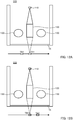
- FIGS. 12A and FIG. 12B are diagrams for explaining a light detection method in a conventional light detection sensor 200 described in PTLs 1 and 2.
- the light detection sensor 200 illustrated in FIGS. 12A and 12B comprises a light source 130 that radiates light toward a predetermined detection region through which a detection target passes, a lens unit 120 that collects light from the detection region, and a light receiving element 110.
- the arrows in FIGS. 12A and 12B indicate the transport direction of a transported object.
- the light source 130 starts radiation of excitation light at the timing when a part TA1 of a detection target attached to a transported object is transported upstream of the detection region, continues the radiation of the excitation light for a predetermined period, and then stops the radiation of the excitation light.
- the light receiving element 110 detects afterglow from the part TA1 of the detection target.
- the light receiving element 110 detects afterglow from the other part TB1 of the detection target.
- the conventional light detection sensor 200 detects a series of afterglow radiated from different parts of the detection target, and thus the decay characteristics of the afterglow of the detection target may not be accurately detected.
- the detection target is an ink containing a luminescent material, for example, the ink may be unevenly applied, result in difference in the intensity of the afterglow radiated depending on the location. In such a case, it is difficult to calculate a correct afterglow decay characteristic of the detection target from the intensity of the detected afterglow.
- the invention described in PTL 3 has a configuration with each photosensor directly detecting afterglow, not thorough a lens, from the luminescent material and with the plurality of photosensors disposed side by side in the transport direction of the luminescent material. Such configuration increases the size of the device. Such a configuration also needs to increase the intervals between the photosensors disposed in the transport direction, and thus it is difficult to detect the decay characteristic of afterglow having a short decay time.
- a plurality of sensors are disposed side by side at short intervals in the transport direction of a detection target in the invention described in PTL 4, and thus the decay characteristics of afterglow having a short decay time can be detected.
- the light radiated from the detection target is collected by using two lenses disposed side by side perpendicularly to the transport direction of the detection target and a beam splitter disposed between these lenses in PTL 4. This configuration increases the size of the device in the direction perpendicular to the transport direction.
- the invention described in PTL 4 detects afterglow from a detection target after the detection target passes a light irradiation region, but the detection target may be irradiated with the light from the light source, which is always lit, after the detection target passes the light irradiation region. This configuration makes accurate detection of the decay characteristics of the afterglow difficult.
- An object of the present invention is to provide a light detection sensor, a light detection device, a sheet processing apparatus and light detection method which accurately detect the emission characteristic of phosphorescence and succeed in downsizing the devices used therein.
- a light detection sensor of the present invention comprises a light source that irradiates a detection target with light; a rod lens unit that collects the light from the detection target; a first light receiving element that detects the light that has passed through the rod lens unit; and a second light receiving element that detects the light that has passed through the rod lens unit, at a position different from a position at which the first light receiving element detects the light.
- a light detection device of the present invention comprises the above-described light detection sensor; a transport unit that transports an object to be transported (herein also referred to as "transported object”); and a control unit that controls the light detection sensor and the transport unit, in which the first light receiving element and the second light receiving element are disposed side by side in a transport direction of the transport unit, and the control unit controls the first light receiving element and the second light receiving element to detect the light from the detection target located at one position on the transported object.
- a sheet processing apparatus of the present invention comprises the above-described light detection device; a storage unit that stores reference data regarding the detection target; and a recognition unit that recognizes authenticity of a sheet based on the reference data and the light detected by the first light receiving element and the second light receiving element, the sheet being the transported object.
- a light detection method of the present invention comprises transporting by a transport unit a transported object comprising a detection target; and controlling the transport unit and a light detection sensor comprising a first light receiving element and a second light receiving element disposed side by side in a transport direction of the transported object that is transported in the transporting, in which in the controlling, the first light receiving element and the second light receiving element are caused to detect light from the detection target located at one position on the transported object.
- the light detection sensor, light detection device, sheet processing apparatus and light detection method of the present invention are capable of accurately detecting the emission characteristic of phosphorescence and downsizing the devices used therein.
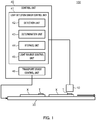
- FIG. 1 illustrates exemplary functions and configuration of units in light detection device 100 of the present invention.
- Light detection device 100 is used for deciding the authenticity of a transported object X which has a detection target T attached thereto, and which is transported by a transport device 30.
- the transported object X is a sheet medium such as a bill (banknote) or a valuable security
- the detection target T is a security mark printed on the banknote or the like with an ink comprising a phosphorescent radiation material that radiates phosphorescence when electrons in the molecules are excited.
- the phosphorescent radiation material applied to the transported object X is predetermined according to the type of transported object X.
- the light detection device 100 comprises the transport device 30, a light detection sensor 10, and a control unit 40.
- phosphorescence refers to light radiated by a phosphor when the phosphor is irradiated with excitation light, or a phenomenon of radiating such light.
- the phosphorescence is light radiated by a phosphor during and after irradiation with excitation light.
- the phosphorescence radiated by the phosphor after the irradiation is referred to as afterglow.
- the transport device 30 is a device for continuously transporting the transported object X, to which the detection target T is attached at a predetermined position, in the direction indicated by the arrow in FIG. 1 .
- the transport device 30 is composed of a belt conveyer, a roller conveyer, a floating transport device, and/or the like in accordance with characteristics such as the shape of the transported object X.
- the embodiment 1 of the present invention describes the transport device 30 composed of a belt conveyer.
- the belt conveyer comprises a belt and a pulley for driving the belt.
- a rotary encoder for detecting the number of rotations (rotation angle) of the pulley is connected to the rotation shaft of the pulley.
- the transport device 30 comprises a passage detection sensor (not illustrated), for detecting passage of the transported object X, in the upstream side of the light detection sensor 10 in the transport direction of the transported object X.
- the control unit 40 is a control device for controlling the light detection sensor 10, the transport device 30 and the like.
- the control unit 40 is composed of an electric power source, a CPU, a memory and the like, and comprises a light detection sensor control unit 41 and a transport device control unit 46.
- the transport device control unit 46 is a control unit for controlling the operation of the transport device 30.
- the transport device control unit 46 calculates information regarding the presence position of the detection target T such as a moving distance of the belt, that is, a moving distance of the detection target T, based on the number of pulses of the rotary encoder after the passage detection sensor detects the passage of the transported object X.
- the light detection sensor control unit 41 comprises a detection unit 42, a determination unit 43, a storage unit 44 and a light source control unit 45.
- the detection unit 42 receives a light detection signal output from the light detection sensor 10.
- the detection unit 42 calculates the intensity of the radiation light radiated by the detection target T based on the light detection signal.
- the storage unit 44 stores information such as the intensity of each wavelength band of the radiation light radiated from the true detection target T, the decay time constant ⁇ of the afterglow to be described below.
- the information is reference data serving as the base for deciding the type or authenticity of the detection target T.
- the determination unit 43 compares the intensity of the radiation light obtained by the detection unit 42 with the intensities stored as the reference values in the storage unit 44 to determine the substance comprised in the detection target T and decide the type or authenticity of the detection target T.
- the determination unit 43 can also decide the type or authenticity of the detection target T by calculating the decay time constant ⁇ of phosphorescence and determining the substance included in the detection target T based on the decay time constant ⁇ of the phosphorescence.
- the light source control unit 45 is a control unit for turning on and off (in other words, lighting and extinction of) a light source of the light detection sensor 10.
- the light source control unit 45 turns on and off the light source based on information regarding the presence position of the detection target T calculated by the transport device control unit 46.
- FIG. 2 illustrates an exemplary configuration of the light detection sensor 10 according to the embodiment 1.
- the light detection sensor 10 is a sensor for detecting light from the detection target T attached to the transported object X.
- the light detection sensor 10 comprises a first light receiving element 11a, a second light receiving element 11b, a rod lens unit 12, a light source 13, a housing 14 and a transparent cover 15.
- the housing 14 is a box body for accommodating the first light receiving element 11a, the second light receiving element 11b, the light source 13 and the rod lens unit 12 in its inside.
- the housing 14 is a rectangular parallelepiped box body that comprises a pair of rectangular side walls 14a disposed so as to face each other. A side where the transported object X passes is an open surface of the housing 14.
- FIG. 2 omits the illustration of the other pair of side walls that are provided perpendicularly to the pair of side walls 14a and a lid that closes the space surrounded by the four side walls from the side opposite to the side where the transparent cover 15 is provided.
- the housing 14 is formed of, for example, a colored synthetic resin having a light shielding property.
- the material that forms the housing 14 is not limited to such a synthetic resin, as long as the material has a light shielding property, and maybe a metal such as aluminum.
- the rectangular transparent cover 15 is provided on the surface of the housing 14 where the surface faces the lid.
- the transparent cover 15 is formed of a transparent synthetic resin. Light radiated by the light source 13 and light to be received by the first light receiving element 11a and the second light receiving element 11b pass through the transparent cover 15.
- the light detection sensor 10 radiates light toward the detection target T through the transparent cover 15 and also receives light from the detection target T.
- the transparent cover 15 may be formed of glass.
- the first light receiving element 11a and the second light receiving element 11b are photodetectors that receive light from the detection target T and output electric signals.
- the first light receiving element 11a and the second light receiving element 11b are, for example, Si photodiodes.
- the materials and structures of the first light receiving element 11a and the second light receiving element 11b are not particularly limited.
- the first light receiving element 11a and the second light receiving element 11b are disposed side by side in the normal direction of the pair of side walls 14a.
- the normal direction herein is the same as the transport direction of the transported object X.
- the first light receiving element 11a and the second light receiving element 11b each comprise a plurality of light receiving elements, and the plurality of light receiving elements are arranged linearly along the normal direction of the other pair of side walls.
- Each light receiving element comprises optical filters individually transmitting different types of light in the bands of, for example, three primary colors, namely R (red), G (green) and B (blue), UV (ultraviolet) and IR (infrared).
- the first light receiving element 11a and the second light receiving element 11b do not need to comprise all these types of optical filters, and may comprise at least one of these optical filters.
- the light receiving element may receive light in a wide range of wavelengths by not providing an optical filter that transmits light in a specific band or by providing a transparent filter. For example, when the light from the detection target T is weak, receiving light in a wide range of wavelengths may improve the S/N ratio.
- the light source 13 is a projector that irradiates the detection target T with light.
- the light source 13 comprises, for example, a visible light source that radiates visible light such as white light, an IR light source that radiates infrared light, and a UV light source that radiates ultraviolet light.
- the light source 13 can radiate these different types of light having the plurality of wavelength bands simultaneously or individually.
- a light shielding means 16 such as a light shielding plate is provided between the light source 13, and the first light receiving element 11a and the second light receiving element 11b. The light shielding means 16 prevents the first light receiving element 11a and the second light receiving element 11b from directly receiving light from the light source 13 that does not pass through the transparent cover 15.
- ultraviolet light is excitation light that excites the detection target T.
- the detection target T is excited by light in a wavelength band unique to the detection target T.
- the light source 13 is provided at positions on both sides of the rod lens unit 12 which are closer to the transparent cover 15 than the first light receiving element 11a and the second light receiving element 11b.
- the rod lens unit 12 is a lens unit that collects light from the detection target T.
- the rod lens unit 12 is, for example, a rod lens array comprising a plurality of rod lenses arranged linearly along the direction in which the plurality of light receiving elements of the first light receiving element 11a and the second light receiving element 11b described above are arranged.
- the rod lens is a gradient index lens, and the rod lens unit 12 forms erected images at the same magnification on the first light receiving element 11a and the second light receiving element 11b.
- a light detection method by the light detection device 100 according to the embodiment 1 will be described with reference to FIG. 3 , and FIGS. 4A and 4B .
- the excitation light is not limited to ultraviolet light in the present invention.
- the wavelength of excitation light varies depending on the phosphorescent radiation material, and in addition to ultraviolet light, visible light such as red, blue, or green or infrared light may also become excitation light.
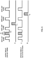
- FIG. 3 illustrates the relationship between a lighting timing of the light source 13 and a detection timing of each light receiving element in the light detection sensor 10 according to the embodiment 1.
- the light source 13 irradiates the detection target T with ultraviolet light at a timing before a timing T1 when the detection target T reaches the detection region A.
- the light source control unit 45 turns on the light source 13 at a timing when the detection target T reaches a position upstream of the predetermined detection region A. The detection target T is then excited and radiates phosphorescence.
- the light source control unit 45 turns off the light source 13 at a timing T0.
- the detection target T thus radiates afterglow.
- the first light receiving element 11a detects light from the detection region A at the first timing T1 when the detection target T reaches the detection region A.
- the second light receiving element 11b detects light from the detection region B at a timing T2 when the detection target T reaches the detection region B.
- FIGS. 4A and 4B are diagrams for explaining the light detection method in the light detection sensor 10 according to the embodiment 1.
- the arrows in FIGS. 4A and 4B indicate the transport direction of the transported object X transported by the transport device 30.
- FIG. 4A shows a case where the first light receiving element 11a detects light from the detection region A at the first timing T1 when the detection target T reaches the detection region A.
- the detection region A is, for example, a region located in a position symmetrical with the first light receiving element 11a with respect to a surface that bisects the rod lens unit 12 in the axial direction.
- the detection region A is located in the upstream side of the rod lens unit 12 in the transport direction of the transported object X.
- FIG. 4B shows a case where the second light receiving element 11b detects light from the detection region B at the second timing T2 when the detection target T reaches the detection region B.
- the detection region B is, for example, a region located in a position symmetrical with the second light receiving element 11b with respect to the surface that bisects the rod lens unit 12 in the axial direction.
- the detection region B is located in the downstream side of the rod lens unit 12 in the transport direction of the transported object X.
- FIG. 5 illustrates the relationship between a light emission timing in the light detection sensor 10 according to the embodiment 1 and the intensity of light radiated by the detection target T.
- the light source control unit 45 turns on the light source 13 at the timing when the detection target T reaches a predetermined position upstream of the detection region A illustrated in FIG. 4A .
- the light source control unit 45 continues lighting of the light source 13 for a predetermined time while the transported object X is transported in the upstream side of the detection region A.
- the intensity of the phosphorescence radiated from the detection target T gradually increases with the passage of time.
- the light source control unit 45 turns off the light source 13 at the timing T0, the light source 13 stops the irradiation of the detection target T with ultraviolet light. After the irradiation with ultraviolet light stops, the detection target T radiates afterglow, but the intensity of the afterglow is attenuated with the passage of time.
- the first light receiving element 11a detects the light from the detection region A
- the second timing T2 when the detection target T reaches the detection region B illustrated in FIG. 4B the second light receiving element 11b detects the light from the detection region B.
- the determination unit 43 calculates the decay time constant ⁇ of the afterglow of the detection target T from the intensity of the light from the detection region A and the intensity of the light from the detection region B.
- the decay time constant of the afterglow can be calculated based on an equation 1 below.
- ⁇ is the decay time constant of the afterglow
- t1 and t2 are the elapsed times from the extinction of the light source 13 to the first timing T1 and the second timing T2, respectively
- P1 and P2 are the intensities of the afterglow detected at the first timing T1 and the second timing T2, respectively.
- Each phosphorescent radiation material has its unique decay time constant (the time required for the phosphorescent intensity becomes 1/e).
- the phosphorescence intensity decay curve obtained with the abscissa representing the elapsed time after the extinction of the light source 13 and the ordinate representing the phosphorescence intensity thus varies depending on phosphorescent radiation materials.
- the determination unit 43 compares the calculated decay time constant ⁇ of the afterglow with the reference values of the decay time constants ⁇ of afterglow of the detection target T stored in the storage unit 44, to determine the substance comprised in the detection target T, and to decide the authenticity of the detection target T.
- the second light receiving element 11b can detect, at different timings, light radiated from a position of the detection target T the same as the position from which the light detected by the first light receiving element 11a is radiated.
- the embodiment 1 of the present invention can detect the intensity of afterglow radiated from a predetermined position of the detection target T at different timings.
- This configuration can calculate an accurate decay time constant ⁇ of the afterglow radiated from the detection target T, and decide the authenticity of the detection target T.
- one rod lens unit 12 forms images of the detection target T on the first light receiving element 11a and the second light receiving element 11b in the embodiment 1.
- Such configuration allows providing of a lens unit for every light receiving element to become unnecessary, and thus the light detection sensor 10 and the light detection device 100 comprising the light detection sensor 10 can be downsized.
- One rod lens unit 12 forms images of the detection target T on both the first light receiving element 11a and the second light receiving element 11b.
- Such a configuration can shorten the distance between the detection regions A and B, and as a result, can shorten the time interval for detecting the intensities of afterglow.
- the intensities of afterglow can be thus detected even for the detection target T whose afterglow has a small decay time constant ⁇ .
- the distances from the first light receiving element 11a and the second light receiving element 11b to the rod lens portion 12 may be different in the transport direction. Each distance can be selected according to the purpose of detection.
- the light detection device 100 is, for example, provided in a sheet processing apparatus.
- the sheet processing apparatus recognizes the type of sheet to be processed such as a banknote or a valuable security based on the image read from the sheet, and also recognizes the authenticity of the sheet by deciding the type and authenticity of the detection target T attached to the sheet based on light detected by the first light receiving element 11a and the second light receiving element 11b of the light detection sensor 10, and on the reference data stored in the storage unit 44.
- the light detection sensor control unit 41 does not need to be provided with the determination unit 43, the storage unit 44, and the like.
- the sheet processing apparatus includes a transport unit for a transporting sheet, a storage unit that stores reference data for recognizing the sheet, a recognition unit for recognizing the transported sheet, and a control unit for controlling the entire sheet processing apparatus comprising the transport unit, the storage unit and the recognition unit.
- the recognition unit recognizes the type and authenticity of a sheet that is a transported object.
- the recognition unit comprises, in addition to the light detection sensor 10, an image sensor for reading an images of a sheet, a magnetic sensor for reading magnetic information on the sheet, and the like.
- the recognition unit recognizes the type of sheet by comparing the read image with the reference data, and also recognizes the authenticity of the sheet by comparing at least one of the characteristic of the light detected by the light detection sensor 10, the image read by the image sensor, the magnetic information read by the magnetic sensor, and the like with the stored reference data corresponding to the recognized sheet type.
- the sheet processing apparatus processes the sheet based on the result recognized by the recognition unit.
- An example of the sheet processing apparatus is a banknote processing apparatus that transports the input banknotes one by one, recognizes the denomination and authenticity of the transported banknote, and performs processing based on the recognition result.
- Examples of the processing include a storing process transporting a banknote that is recognized as authentic to store the banknote in a storing unit according to the denomination, and a returning process transporting a banknote that cannot be recognized or a banknote that is recognized as counterfeit to a return unit to return the banknote.
- Examples of the bills (banknotes) include banknotes with patterns printed on paper sheets, or banknotes with patterns printed on resin sheets referred to as polymer banknotes.
- the first light receiving element 11a and the second light receiving element 11b detect the intensity of the afterglow radiated from the detection target T.
- the light detection device 100 may detect phosphorescence radiated during the irradiation with excitation light. The modification will be described below.
- the light source control unit 45 turns on the light source 13 at the first timing T1 when the detection target T reaches the detection region A illustrated in FIG. 4A .
- the first light receiving element 11a detects light from the detection region A at the first timing T1 when the detection target T reaches the detection region A.
- the light source control unit 45 continues lighting of the light source 13. At the second timing T2 when the detection target T reaches the detection region B illustrated in FIG. 4B , the second light receiving element 11b detects the light from the detection region B. The light source control unit 45 turns off the light source 13 after the detection target T passes the detection region B.
- the second light receiving element 11b thus can detect light from a position of the detection target T, where the light detected by the first light receiving element 11a is radiated, at different timings.
- the light detection device 100 can detect the intensity of phosphorescence radiated from a predetermined position of the detection target T at a plurality of different timings during the irradiation with the excitation light.
- the determination unit 43 thus can calculate the emission characteristic of the phosphorescence radiated from the detection target T during the irradiation with the excitation light and decide the authenticity of the detection target T by using the emission characteristic of the phosphorescence.
- the lighting timing of the light source 13 is the timing at which the detection target reaches the detection region A, but the lighting timing may be earlier.
- the light detection device 100 may detect phosphorescence radiated from the detection target T during the irradiation with ultraviolet light at the detection region A illustrated in FIG. 4A , and detect afterglow radiated from the detection target T at the detection region B illustrated in FIG. 4B .
- the modification will be described below.
- the light source control unit 45 turns on the light source 13 at a timing when the detection target T reaches the detection region A.
- the first light receiving element 11a detects light from the detection region A at the timing when the detection target T reaches the detection region A.
- the light source control unit 45 turns off the light source 13 after the detection target T passes the detection region A.
- the second light receiving element 11b detects light from the detection region B at a timing when the detection target T reaches the detection region B.
- the light detection device 100 thus can detect the intensity of phosphorescence radiated from the detection target T during the irradiation with ultraviolet light, and the intensity of afterglow radiated from the detection target T after the irradiation with the ultraviolet light is stopped.
- the determination unit 43 thus can decide the authenticity of the detection target T by comparing the intensities of the radiation light with the reference values of the intensities stored in the storage unit 44.
- the lighting timing of the light source 13 is the timing at which the detection target reaches the detection region A, but the lighting timing may be earlier.
- the light detection sensor 10 is further provided with a third light receiving element which is an imaging element for acquiring an image of the detection target T.
- a third light receiving element which is an imaging element for acquiring an image of the detection target T.
- FIG. 6 illustrates an exemplary configuration of the light detection sensor 10 according to the embodiment 2.
- the light detection sensor 10 comprises, inside the housing 14, the first light receiving element 11a, the second light receiving element 11b, the third light receiving element 11c, the light source 13 and the rod lens unit 12.
- the third light receiving element 11c is provided at an intermediate position between the first light receiving element 11a and the second light receiving element 11b.
- the third light receiving element 11c is a line sensor for acquiring an image of the detection target T.
- the third light receiving element 11c comprises a plurality of light receiving elements which are arranged linearly so as to be parallel to the first light receiving elements 11a and to the second light receiving elements 11b.
- Each light receiving element comprises filters individually transmitting different types of light in the bands of, for example, three primary colors, namely R (red), G (green) and B (blue), UV (ultraviolet) and IR (infrared).
- the third light receiving element 11c acquires an image of the detection target T located in a detection region C described below.
- the light receiving element may receive light in a wide range of wavelengths by not providing an optical filter that transmits light in a specific band or by providing a transparent filter, as in the embodiment 1.
- a light detection method by the light detection device 100 according to the embodiment 2 will be described with reference to FIG. 7 and FIG. 8 .
- the light source 13 radiates ultraviolet light as excitation light
- the excitation light is not limited to ultraviolet light.
- the third light receiving element 11c acquires the image of the detection target T during irradiation with white light, but the irradiation light may be any other visible light.
- the white light radiated by the light source 13 does not affect the intensity of afterglow radiated by the detection target.
- FIG. 7 is a diagram for explaining the light detection method by the light detection device 100 according to the embodiment 2.
- the arrows in FIG. 7 indicate the transport direction of the transported object X transported by the transport device 30.
- Dotted lines in FIG. 7 indicate a case where the first light receiving element 11a detects light from the detection region A via the rod lens unit 12 at the first timing T1 when the detection target T reaches the detection region A.
- the detection region A is, for example, a region located in a position symmetrical with the first light receiving element 11a with respect to a surface that bisects the rod lens unit 12 in the axial direction, as in the embodiment 1.
- the dashed-dotted lines in FIG. 7 indicate a case where the third light receiving element 11c detects light from the detection region C via the rod lens unit 12 at the second timing T2 when the detection target T reaches the detection region C.
- the detection region C is, for example, a region located in a position symmetrical with the third light receiving element 11c with respect to the surface that bisects the rod lens unit 12 in the axial direction.
- the third light receiving element 11c may acquire a transmission image of the detection target T.
- a light source different from the light source 13 is provided at a position facing the third light receiving element 11c with the detection region C interposed therebetween.
- the dashed-two dotted lines in FIG. 7 indicate a case where the second light receiving element 11b detects light from the detection region B via the rod lens unit 12 at the third timing T3 when the detection target T reaches the detection region B.
- the detection region B is, for example, a region located in a position symmetrical with the second light receiving element 11b with respect to the surface that bisects the rod lens unit 12 in the axial direction, as in the embodiment 1.
- FIG. 8 illustrates the relationship between a lighting timing of each light source and a detection timing of each light receiving element in the light detection sensor 10 according to the embodiment 2.
- FIG. 8 illustrates the lighting timings of the light source 13 when two detection targets provided on the transported object X pass the detection regions A, C, and B of the light detection sensor 10, and the detection timing of each light receiving element.
- detection target TA a detection target on the downstream side in the transport direction
- detection target TB a detection target on the upstream side of the detection target TA
- the light source control unit 45 controls a white light source of the light source 13 to blink, for example, four times at predetermined time intervals. During each lighting period of the white light source, the third light receiving element 11c acquires an image of the transported object X located in the detection region C.
- a period during which the white light source is turned off between the first lighting and the second lighting of the white light source is referred to as a first extinction period
- a period during which the white light source is turned off between the second lighting and the third lighting of the white light source is referred to as a second extinction period
- a period during which the white light source is turned off between the third lighting and the fourth lighting of the white light source is referred to as a third extinction period.
- the light source control unit 45 turns on a UV light source for a predetermined time at a timing when the detection target TA reaches the detection region C in the first extinction period.
- the third light receiving element 11c acquires an image of the detection target TA located in a detection region C during the lighting of the UV light source.
- the detection target TB on the upstream side of the detection target TA is located upstream of the detection region A illustrated in FIG. 7 and is excited by the ultraviolet light radiated from the UV light source that continues to be lit.
- the light source control unit 45 then turns off the UV light source at the timing T0 when the detection target TA passes the detection region C.
- the first light receiving element 11a detects light from the detection region A at the first timing T1 when the detection target TB reaches the detection region A in the second extinction period.
- the second light receiving element 11b detects light from the detection region B at the second timing T2 when the detection target TB reaches the detection region B in the third extinction period in the light source control unit 45.
- FIG. 9 illustrates the relationship between a light emission timing in the light detection sensor 10 according to the embodiment 2 and the intensity of light radiated by the transported object X.
- the light source control unit 45 turns on the UV light source of the light source 13 at the timing when the detection target TA of the transported object X reaches the detection region C illustrated in FIG. 7 .
- the third light receiving element 11c detects light from the detection region C.
- the detection target TB is located upstream of the detection region A, and the detection target TB is irradiated with ultraviolet light that is excitation light.
- the intensity of the phosphorescence radiated from the detection target TB gradually increases with the passage of time.
- the light source control unit 45 turns off the light source 13 at a timing T0. After the irradiation with the ultraviolet light from the light source 13 stops, the detection target TB radiates afterglow, but the intensity of the afterglow is attenuated with the passage of time.
- the first light receiving element 11a detects light from the detection region A at the first timing T1 when the detection target TB reaches the detection region A.
- the second light receiving element 11b detects the light from the detection region B at the second timing T2 when the detection target TB reaches the detection region B.
- the determination unit 43 calculates the decay time constant ⁇ of afterglow of the detection target TB from the intensity of the afterglow detected at the detection region A and the intensity of the afterglow detected at the detection region B.
- the determination unit 43 compares the calculated decay time constant ⁇ of the afterglow with the reference values of the decay time constants ⁇ of afterglow of the detection target T stored in the storage unit 44, to determine the substance comprised in the detection target T, and to decide the type and authenticity of the detection target T.
- the determination unit 43 compares the image of the transported object X acquired by the third light receiving element 11c during the irradiation with the white light, with images of the transported object X stored in the storage unit 44, which serve as the reference, to decide the type and authenticity of the transported object X.
- the determination unit 43 further decides the type and authenticity of the detection target TA by using the image of the detection target TA, which is being irradiated with the ultraviolet light, acquired by the third light receiving element 11c.
- the embodiment 2 of the present invention can capture the images of the detection targets TA and TB.
- the light detection device 100 of the present invention thus can further decide the type and authenticity of the detection target TA by using the captured image, in addition to the decay time constant ⁇ of the afterglow of the detection target TB.
- the light detection device 100 of the present invention can accurately recognize the type and authenticity of the transported object X by deciding the type and authenticity of the detection target T.
- the light detection sensor 10 and light detection device 100 comprising the detection sensor 10 can be downsized in the embodiment 2 as the third light receiving element 11c is disposed between the first light receiving element 11a and the second light receiving element 11b, and the rod lens unit 12 that forms images on the first light receiving element 11a and the second light receiving element 11b is the same as the rod lens unit 12 that forms an image on the third light receiving element 11c.
- the light detection device 100 according to the embodiment 2 is, for example, provided in a sheet processing apparatus.
- the sheet processing apparatus can recognize the type or the authenticity of a sheet to be processed such as a banknote or a valuable security by deciding the type and authenticity of the detection target T attached to the sheet based on light detected by the first light receiving element 11a and the second light receiving element 11b of the light detection sensor 10, an image acquired by the third light receiving element 11c, and the reference data stored in the storage unit 44.
- the sheet processing apparatus firstly recognizes the type of sheet based on the image acquired by the third light receiving element 11c, and secondly recognizes the authenticity of the sheet based on whether or not a predetermined detection target T is detected from the sheet.
- a control unit (not illustrated) for controlling the sheet processing apparatus may comprise a storage unit that stores reference data regarding the detection target T, a recognition unit for recognizing the authenticity of sheets, and the like.
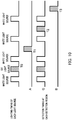
- FIG. 10 illustrates the relationship between a lighting timing of each light source and a detection timing of each light receiving element according to the modification 1 of the embodiment 2.
- the light source control unit 45 controls a white light source of the light source 13 to blink, for example, four times at predetermined time intervals. During each lighting period of the white light source, the third light receiving element 11c acquires an image of the transported object X located in the detection region C.
- the light source control unit 45 turns on a UV light source for a predetermined time at a timing when the detection target TA reaches the detection region C in the first extinction period.
- the third light receiving element 11c acquires an image of the detection target TA located in a detection region C during the lighting of the UV light source.
- the detection target TB on the upstream side of the detection target TA is located upstream of the detection region A illustrated in FIG. 7 and is excited by the ultraviolet light radiated from the UV light source that continues to be lit.
- the light source control unit 45 turns off the UV light source at the timing T0 when the detection target TA passes the detection region C.
- the first light receiving element 11a detects light from the detection region A at the first timing T1 when the detection target TB reaches the detection region A in the second extinction period.
- the third light receiving element 11c detects light from the detection region C at the second timing T2 when the detection target TB reaches the detection region C in the third extinction period.
- the second light receiving element 11b further detects the light from the detection region B at the third timing T3 when the detection target TB reaches the detection region B after the fourth lighting period of the white light source passes.
- the light detection device 100 thus can detect the afterglow from the detection target TB by the first light receiving element 11a, the second light receiving element 11b and the third light receiving element 11c.
- the light detection device 100 according to the modification 1 can calculate the decay characteristics of afterglow from three detection results of the afterglow, and thus this calculation of the decay characteristics is more accurate than the calculation from the detection only by the first light receiving element 11a and second light receiving element 11b.
- the detected value is corrected according to the light receiving area of each light receiving element.
- the third light receiving element 11c acquires the image of the detection target TA located in the detection region C during the lighting of the UV light source.
- the first light receiving element 11a may acquire the image of the detection target TB located in the detection region A during the lighting of the UV light source.
- FIG. 11 illustrates the relationship between a lighting timing of each light source and a detection timing of each light receiving element according to the modification 2 of the embodiment 2.
- the light source control unit 45 controls a white light source of the light source 13 to blink, for example, four times at predetermined time intervals. During each lighting period of the white light source, the third light receiving element 11c acquires an image of the transported object X located in the detection region C.
- the light source control unit 45 turns on a UV light source for a predetermined time at the first timing T1 when the detection target TB reaches the detection region A in the first extinction period. During the lighting of the UV light source, the first light receiving element 11a detects light from the detection region A.
- the light source control unit 45 turns off the UV light source at the timing T0 when the detection target TB passes the detection region A.
- the third light receiving element 11c detects light from the detection region C at the second timing T2 when the detection target TB reaches the detection region C in the second extinction period.
- the second light receiving element 11b detects light from the detection region B at the third timing T3 when the detection target TB reaches the detection region B in the third extinction period.
- the light receiving areas of the second light receiving element 11b and the third light receiving element 11c are different, even if light of the same intensity is received, the output differs depending on the light receiving area. In such a case, the detected value is corrected according to the light receiving area of each light receiving element.
- the light detection device 100 thus can detect phosphorescence during irradiation with ultraviolet light and also calculate the decay time constant ⁇ of afterglow.
- the relationship between the light emission timing in the light detection sensor 10 and the intensity of the light radiated by the transported object X as illustrated in FIG. 9 can be obtained by the detection from the same position (detection target TB), namely one position, on the transported object X.
- the first light receiving element 11a, the second light receiving element 11b, and the third light receiving element 11c can detect phosphorescence emitted from the detection target TB during the irradiation with ultraviolet light.
- the modification will be described below.
- the light source control unit 45 turns on a UV light source in the light source 13 at a timing when the detection target TB reaches the detection region A illustrated in FIG. 7 .
- the first light receiving element 11a detects light from the detection region A at this timing.
- the light source control unit 45 continues lighting of the light source 13.
- the third light receiving element 11c detects light from the detection region C at a timing when the detection target T reaches the detection region C.
- the second light receiving element 11b detects light from the detection region B at a timing when the detection target T reaches the detection region B.
- the light detection device 100 thus can detect phosphorescence radiated from the detection target TB by the first light receiving element 11a, the second light receiving element 11b and the third light receiving element 11c.
- the light detection device 100 thus can calculate the emission characteristic of the phosphorescence from three phosphorescence data, and thus the detection of the emission characteristic of the phosphorescence is more accurate than the detection of the phosphorescence only by the first light receiving element 11a and second light receiving element 11b.
- the light receiving areas of the first light receiving element 11a, the second light receiving element 11b, and the third light receiving element 11c are different, even if light of the same intensity is received, the output differs depending on the light receiving area. In such a case, the detected value is corrected according to the light receiving area of each light receiving element.
- the rod lens unit 12 comprising at least one rod lens is used as the lens for collecting light from the detection target T, but the lens for collecting the light from the detection target T is not limited to this configuration.
- a lens unit in which a plurality of spherical lenses are arranged may be used.
- using the rod lens can shortens the optical distance, thereby downsizing the light detection sensor.
- the first light receiving element 11a and the second light receiving element 11b are disposed at positions away from the central axis of the rod lens unit 12, and thus images formed on the first light receiving element 11a and the second light receiving element 11b may be blurred or distorted.
- blurring and distortion of the formed image can be suppressed by directing the light receiving surfaces of the first light receiving element 11a and the second light receiving element 11b toward the rod lens unit 12 side, or providing a prism or the like to adjust the optical path length of the light incident on the first light receiving element 11a and the second light receiving element 11b.
- the first light receiving element 11a and the second light receiving element 11b detect phosphorescence (afterglow), but fluorescence during the irradiation of the detection target T with excitation light may be detected.
- the light detection device 100 can decide the authenticity of the detection target T based on the intensity of the detected fluorescence and the intensities stored as the reference values in the storage unit 44.
- the first light receiving element 11a and the second light receiving element 11b detect phosphorescence (afterglow), but reflected light from the detection target T may be detected.
- the first light receiving element 11a and the second light receiving element 11b detect reflected light from the detection target T.
- the light source control unit 45 turns on a white light source of the light source 13 at a timing when the detection target T reaches the detection region A illustrated in FIG. 7 .
- the first light receiving element 11a detects light from the detection region A at this timing.
- the second light receiving element 11b detects light from the detection region B at a timing when the detection target T reaches the detection region B.
- the determination unit 43 decides the authenticity of the rainbow hologram that is the detection target T by deciding whether or not the color of light detected by the first light receiving element 11a and the color of light detected by the second light receiving element 11b match the reference colors of the detection target T stored in the storage unit 44.
- the first light receiving element 11a and the second light receiving element 11b also detect reflected light from the detection region A and the detection region B when the detection target T is an ink such as an optically variable ink (OVI).
- OPI optically variable ink
- the determination unit 43 decides the authenticity of the OVI of the detection target T by deciding whether or not the color of light detected by the first light receiving element 11a and the color of light detected by the second light receiving element 11b match the reference colors of the detection target T stored in the storage unit 44.
- the present invention can be widely used in a light detection sensor, a light detection device, a sheet processing apparatus and a light detection method.
Landscapes
- Physics & Mathematics (AREA)
- General Health & Medical Sciences (AREA)
- Health & Medical Sciences (AREA)
- General Physics & Mathematics (AREA)
- Spectroscopy & Molecular Physics (AREA)
- Toxicology (AREA)
- Analytical Chemistry (AREA)
- Immunology (AREA)
- Life Sciences & Earth Sciences (AREA)
- Chemical & Material Sciences (AREA)
- Pathology (AREA)
- Biochemistry (AREA)
- Engineering & Computer Science (AREA)
- Business, Economics & Management (AREA)
- Accounting & Taxation (AREA)
- Finance (AREA)
- Computer Vision & Pattern Recognition (AREA)
- Textile Engineering (AREA)
- Inspection Of Paper Currency And Valuable Securities (AREA)
- Investigating, Analyzing Materials By Fluorescence Or Luminescence (AREA)
- Investigating Materials By The Use Of Optical Means Adapted For Particular Applications (AREA)
Abstract
Description
- The present invention relates to a light detection sensor, a light detection device, a sheet processing apparatus and a light detection method.
- Security marks having predetermined optical characteristics are conventionally used to recognize authenticity of sheets, such as banknotes and documents, products, and the like. An example of such security marks includes a special material that does not radiate radiation light under visible light but radiates radiation light only when irradiated with excitation light of a predetermined wavelength such as ultraviolet light. The security mark is provided on a sheet or product package by printing or the like for determining the authenticity of the sheet, product or the like from the radiation state of the radiation light. Phosphorescence radiated at the time of excitation light irradiation and afterglow radiated after the excitation light irradiation are used as the radiation light.
-
PTL 1 discloses a device that irradiates a medium with infrared light or ultraviolet light together with visible light from a light source, and after stopping the irradiation with the light, detects afterglow radiated from the medium with an optical line sensor. - PTL 2 discloses a detection device that allows light radiated from a light source to blink repeatedly for detecting fluorescence and afterglow radiated from a sheet material.
- PTL 3 discloses a device including a light source and a plurality of photosensors disposed side by side in the transport direction of a luminescent material for detecting afterglow from the luminescent material. This device further detects the decay characteristics of the afterglow of the luminescent material from the intensity of the detected afterglow.
- PTL 4 discloses a device that reflects light from a light source into the direction perpendicular to the transport direction of a detection target with a beam splitter, irradiates the detection target with the light, and detects the characteristics of phosphorescence from the detection target by a plurality of light detection sensors disposed in parallel to the transport direction of the detection target.
-
- PTL 1 Japanese Patent Application Laid-Open No.
2016-9445 - PTL 2 Japanese Unexamined Patent Application Publication (Translation of
PCT Application) No. 2001-506001 - PTL 3
EP Patent No. 2718910 - PTL 4 Chinese Patent Application Publication No.
102893309 - The characteristics of phosphorescence include the presence or absence of the phosphorescence (including afterglow), the color of the phosphorescence, and the decay characteristic of the afterglow represented by, for example, the decay time constant of the afterglow. For detecting the decay characteristic of afterglow, it is necessary to detect the intensity of the afterglow from a predetermined position of a detection target more than once at different timings.
- However, the devices described in
PTLs 1 and 2 do not detect afterglow from a predetermined position of a detection target a plurality of times at different timings, and thus cannot detect the decay characteristic of the afterglow. -
FIGS. 12A and FIG. 12B are diagrams for explaining a light detection method in a conventionallight detection sensor 200 described inPTLs 1 and 2. Thelight detection sensor 200 illustrated inFIGS. 12A and 12B comprises alight source 130 that radiates light toward a predetermined detection region through which a detection target passes, alens unit 120 that collects light from the detection region, and alight receiving element 110. The arrows inFIGS. 12A and 12B indicate the transport direction of a transported object. - The
light source 130 starts radiation of excitation light at the timing when a part TA1 of a detection target attached to a transported object is transported upstream of the detection region, continues the radiation of the excitation light for a predetermined period, and then stops the radiation of the excitation light. - When the part TA1 of the detection target is subsequently transported to the detection region, the
light receiving element 110 detects afterglow from the part TA1 of the detection target. When the other part TB1 of the detection target is then transported to the detection region, thelight receiving element 110 detects afterglow from the other part TB1 of the detection target. - The conventional
light detection sensor 200 detects a series of afterglow radiated from different parts of the detection target, and thus the decay characteristics of the afterglow of the detection target may not be accurately detected. When the detection target is an ink containing a luminescent material, for example, the ink may be unevenly applied, result in difference in the intensity of the afterglow radiated depending on the location. In such a case, it is difficult to calculate a correct afterglow decay characteristic of the detection target from the intensity of the detected afterglow. - The invention described in PTL 3 has a configuration with each photosensor directly detecting afterglow, not thorough a lens, from the luminescent material and with the plurality of photosensors disposed side by side in the transport direction of the luminescent material. Such configuration increases the size of the device. Such a configuration also needs to increase the intervals between the photosensors disposed in the transport direction, and thus it is difficult to detect the decay characteristic of afterglow having a short decay time.
- A plurality of sensors are disposed side by side at short intervals in the transport direction of a detection target in the invention described in PTL 4, and thus the decay characteristics of afterglow having a short decay time can be detected. The light radiated from the detection target is collected by using two lenses disposed side by side perpendicularly to the transport direction of the detection target and a beam splitter disposed between these lenses in PTL 4. This configuration increases the size of the device in the direction perpendicular to the transport direction.
- The invention described in PTL 4 detects afterglow from a detection target after the detection target passes a light irradiation region, but the detection target may be irradiated with the light from the light source, which is always lit, after the detection target passes the light irradiation region. This configuration makes accurate detection of the decay characteristics of the afterglow difficult.
- An object of the present invention is to provide a light detection sensor, a light detection device, a sheet processing apparatus and light detection method which accurately detect the emission characteristic of phosphorescence and succeed in downsizing the devices used therein.
- To achieve the above object, a light detection sensor of the present invention comprises a light source that irradiates a detection target with light; a rod lens unit that collects the light from the detection target; a first light receiving element that detects the light that has passed through the rod lens unit; and a second light receiving element that detects the light that has passed through the rod lens unit, at a position different from a position at which the first light receiving element detects the light.
- A light detection device of the present invention comprises the above-described light detection sensor; a transport unit that transports an object to be transported (herein also referred to as "transported object"); and a control unit that controls the light detection sensor and the transport unit, in which the first light receiving element and the second light receiving element are disposed side by side in a transport direction of the transport unit, and the control unit controls the first light receiving element and the second light receiving element to detect the light from the detection target located at one position on the transported object.
- A sheet processing apparatus of the present invention comprises the above-described light detection device; a storage unit that stores reference data regarding the detection target; and a recognition unit that recognizes authenticity of a sheet based on the reference data and the light detected by the first light receiving element and the second light receiving element, the sheet being the transported object.
- A light detection method of the present invention comprises transporting by a transport unit a transported object comprising a detection target; and controlling the transport unit and a light detection sensor comprising a first light receiving element and a second light receiving element disposed side by side in a transport direction of the transported object that is transported in the transporting, in which in the controlling, the first light receiving element and the second light receiving element are caused to detect light from the detection target located at one position on the transported object.
- The light detection sensor, light detection device, sheet processing apparatus and light detection method of the present invention are capable of accurately detecting the emission characteristic of phosphorescence and downsizing the devices used therein.
-
-
FIG. 1 illustrates exemplary functions and configuration of units in a light detection device of the present invention; -
FIG. 2 illustrates an exemplary configuration of a light detection sensor according to anembodiment 1; -
FIG. 3 illustrates the relationship between a lighting timing of a light source and a detection timing of each light receiving element in the light detection sensor according to theembodiment 1; -
FIG. 4A is a diagram for explaining a light detection method in the light detection sensor according to theembodiment 1; -
FIG. 4B is a diagram for explaining the light detection method in the light detection sensor according to theembodiment 1; -
FIG. 5 illustrates the relationship between a light emission timing in the light detection sensor according to theembodiment 1 and the intensity of light radiated by a detection target; -
FIG. 6 illustrates an exemplary configuration of a light detection sensor according to an embodiment 2; -
FIG. 7 is a diagram for explaining a light detection method in the light detection sensor according to the embodiment 2; -
FIG. 8 illustrates the relationship between a lighting timing of each light source and a detection timing of each light receiving element according to the embodiment 2; -
FIG. 9 illustrates the relationship between a light emission timing in the light detection sensor according to the embodiment 2 and the intensity of light radiated by a detection target; -
FIG. 10 illustrates the relationship between a lighting timing of each light source and a detection timing of each light receiving element according tomodification 1 of the embodiment 2; -
FIG. 11 illustrates the relationship between a lighting timing of each light source and a detection timing of each light receiving element according to modification 2 of the embodiment 2; -
FIG. 12A is a diagram for explaining a light detection method in a conventional light detection sensor; and -
FIG. 12B is a diagram for explaining the light detection method in the conventional light detection sensor. - Hereinafter, an
embodiment 1 of the present invention will be described with reference to the drawings. The same components are denoted by the same reference numerals. The drawings schematically illustrate the components for easy understanding. -
FIG. 1 illustrates exemplary functions and configuration of units inlight detection device 100 of the present invention.Light detection device 100 is used for deciding the authenticity of a transported object X which has a detection target T attached thereto, and which is transported by atransport device 30. - For example, the transported object X is a sheet medium such as a bill (banknote) or a valuable security, and the detection target T is a security mark printed on the banknote or the like with an ink comprising a phosphorescent radiation material that radiates phosphorescence when electrons in the molecules are excited. The phosphorescent radiation material applied to the transported object X is predetermined according to the type of transported object X. The
light detection device 100 comprises thetransport device 30, alight detection sensor 10, and acontrol unit 40. - Herein, phosphorescence refers to light radiated by a phosphor when the phosphor is irradiated with excitation light, or a phenomenon of radiating such light. The phosphorescence is light radiated by a phosphor during and after irradiation with excitation light. In particular, the phosphorescence radiated by the phosphor after the irradiation is referred to as afterglow.
- The
transport device 30 is a device for continuously transporting the transported object X, to which the detection target T is attached at a predetermined position, in the direction indicated by the arrow inFIG. 1 . Thetransport device 30 is composed of a belt conveyer, a roller conveyer, a floating transport device, and/or the like in accordance with characteristics such as the shape of the transported object X. Theembodiment 1 of the present invention describes thetransport device 30 composed of a belt conveyer. - The belt conveyer comprises a belt and a pulley for driving the belt. A rotary encoder for detecting the number of rotations (rotation angle) of the pulley is connected to the rotation shaft of the pulley. The
transport device 30 comprises a passage detection sensor (not illustrated), for detecting passage of the transported object X, in the upstream side of thelight detection sensor 10 in the transport direction of the transported object X. - The
control unit 40 is a control device for controlling thelight detection sensor 10, thetransport device 30 and the like. Thecontrol unit 40 is composed of an electric power source, a CPU, a memory and the like, and comprises a light detectionsensor control unit 41 and a transportdevice control unit 46. - The transport
device control unit 46 is a control unit for controlling the operation of thetransport device 30. The transportdevice control unit 46 calculates information regarding the presence position of the detection target T such as a moving distance of the belt, that is, a moving distance of the detection target T, based on the number of pulses of the rotary encoder after the passage detection sensor detects the passage of the transported object X. - The light detection
sensor control unit 41 comprises adetection unit 42, adetermination unit 43, astorage unit 44 and a lightsource control unit 45. - The
detection unit 42 receives a light detection signal output from thelight detection sensor 10. Thedetection unit 42 calculates the intensity of the radiation light radiated by the detection target T based on the light detection signal. - The
storage unit 44 stores information such as the intensity of each wavelength band of the radiation light radiated from the true detection target T, the decay time constant τ of the afterglow to be described below. The information is reference data serving as the base for deciding the type or authenticity of the detection target T. - The
determination unit 43 compares the intensity of the radiation light obtained by thedetection unit 42 with the intensities stored as the reference values in thestorage unit 44 to determine the substance comprised in the detection target T and decide the type or authenticity of the detection target T. Thedetermination unit 43 can also decide the type or authenticity of the detection target T by calculating the decay time constant τ of phosphorescence and determining the substance included in the detection target T based on the decay time constant τ of the phosphorescence. - The light
source control unit 45 is a control unit for turning on and off (in other words, lighting and extinction of) a light source of thelight detection sensor 10. The lightsource control unit 45 turns on and off the light source based on information regarding the presence position of the detection target T calculated by the transportdevice control unit 46. -
FIG. 2 illustrates an exemplary configuration of thelight detection sensor 10 according to theembodiment 1. Thelight detection sensor 10 is a sensor for detecting light from the detection target T attached to the transported object X. Thelight detection sensor 10 comprises a firstlight receiving element 11a, a secondlight receiving element 11b, arod lens unit 12, alight source 13, ahousing 14 and atransparent cover 15. - The
housing 14 is a box body for accommodating the firstlight receiving element 11a, the secondlight receiving element 11b, thelight source 13 and therod lens unit 12 in its inside. Thehousing 14 is a rectangular parallelepiped box body that comprises a pair ofrectangular side walls 14a disposed so as to face each other. A side where the transported object X passes is an open surface of thehousing 14.FIG. 2 omits the illustration of the other pair of side walls that are provided perpendicularly to the pair ofside walls 14a and a lid that closes the space surrounded by the four side walls from the side opposite to the side where thetransparent cover 15 is provided. - The
housing 14 is formed of, for example, a colored synthetic resin having a light shielding property. The material that forms thehousing 14 is not limited to such a synthetic resin, as long as the material has a light shielding property, and maybe a metal such as aluminum. - The rectangular
transparent cover 15 is provided on the surface of thehousing 14 where the surface faces the lid. Thetransparent cover 15 is formed of a transparent synthetic resin. Light radiated by thelight source 13 and light to be received by the firstlight receiving element 11a and the secondlight receiving element 11b pass through thetransparent cover 15. Thelight detection sensor 10 radiates light toward the detection target T through thetransparent cover 15 and also receives light from the detection target T. Thetransparent cover 15 may be formed of glass. - The first
light receiving element 11a and the secondlight receiving element 11b are photodetectors that receive light from the detection target T and output electric signals. The firstlight receiving element 11a and the secondlight receiving element 11b are, for example, Si photodiodes. The materials and structures of the firstlight receiving element 11a and the secondlight receiving element 11b are not particularly limited. - The first
light receiving element 11a and the secondlight receiving element 11b are disposed side by side in the normal direction of the pair ofside walls 14a. The normal direction herein is the same as the transport direction of the transported object X. - The first
light receiving element 11a and the secondlight receiving element 11b each comprise a plurality of light receiving elements, and the plurality of light receiving elements are arranged linearly along the normal direction of the other pair of side walls. - Each light receiving element comprises optical filters individually transmitting different types of light in the bands of, for example, three primary colors, namely R (red), G (green) and B (blue), UV (ultraviolet) and IR (infrared). The first
light receiving element 11a and the secondlight receiving element 11b do not need to comprise all these types of optical filters, and may comprise at least one of these optical filters. In addition, the light receiving element may receive light in a wide range of wavelengths by not providing an optical filter that transmits light in a specific band or by providing a transparent filter. For example, when the light from the detection target T is weak, receiving light in a wide range of wavelengths may improve the S/N ratio. - The
light source 13 is a projector that irradiates the detection target T with light. Thelight source 13 comprises, for example, a visible light source that radiates visible light such as white light, an IR light source that radiates infrared light, and a UV light source that radiates ultraviolet light. Thelight source 13 can radiate these different types of light having the plurality of wavelength bands simultaneously or individually. A light shielding means 16 such as a light shielding plate is provided between thelight source 13, and the firstlight receiving element 11a and the secondlight receiving element 11b. The light shielding means 16 prevents the firstlight receiving element 11a and the secondlight receiving element 11b from directly receiving light from thelight source 13 that does not pass through thetransparent cover 15. - Of these different types of light radiated by the
light source 13, for example, ultraviolet light is excitation light that excites the detection target T. The detection target T is excited by light in a wavelength band unique to the detection target T. - The
light source 13 is provided at positions on both sides of therod lens unit 12 which are closer to thetransparent cover 15 than the firstlight receiving element 11a and the secondlight receiving element 11b. - The
rod lens unit 12 is a lens unit that collects light from the detection target T. Therod lens unit 12 is, for example, a rod lens array comprising a plurality of rod lenses arranged linearly along the direction in which the plurality of light receiving elements of the firstlight receiving element 11a and the secondlight receiving element 11b described above are arranged. The rod lens is a gradient index lens, and therod lens unit 12 forms erected images at the same magnification on the firstlight receiving element 11a and the secondlight receiving element 11b. - A light detection method by the
light detection device 100 according to theembodiment 1 will be described with reference toFIG. 3 , andFIGS. 4A and 4B . In the following, a case where thelight source 13 irradiates the detection target T with ultraviolet light as excitation light will be described as an example. The excitation light is not limited to ultraviolet light in the present invention. The wavelength of excitation light varies depending on the phosphorescent radiation material, and in addition to ultraviolet light, visible light such as red, blue, or green or infrared light may also become excitation light. -
FIG. 3 illustrates the relationship between a lighting timing of thelight source 13 and a detection timing of each light receiving element in thelight detection sensor 10 according to theembodiment 1. As described below, afterglow radiated from the detection target T is detected when the detection target T is located in a detection region A and a detection region B shown inFIGS. 4A and 4B , but as illustrated inFIG. 3 , thelight source 13 irradiates the detection target T with ultraviolet light at a timing before a timing T1 when the detection target T reaches the detection region A. - Specifically, after the passage detection sensor detects the transported object X, the light
source control unit 45 turns on thelight source 13 at a timing when the detection target T reaches a position upstream of the predetermined detection region A. The detection target T is then excited and radiates phosphorescence. - After that, the light
source control unit 45 turns off thelight source 13 at a timing T0. The detection target T thus radiates afterglow. - The first
light receiving element 11a detects light from the detection region A at the first timing T1 when the detection target T reaches the detection region A. In addition, the secondlight receiving element 11b detects light from the detection region B at a timing T2 when the detection target T reaches the detection region B. -
FIGS. 4A and 4B are diagrams for explaining the light detection method in thelight detection sensor 10 according to theembodiment 1. The arrows inFIGS. 4A and 4B indicate the transport direction of the transported object X transported by thetransport device 30. -
FIG. 4A shows a case where the firstlight receiving element 11a detects light from the detection region A at the first timing T1 when the detection target T reaches the detection region A. The detection region A is, for example, a region located in a position symmetrical with the firstlight receiving element 11a with respect to a surface that bisects therod lens unit 12 in the axial direction. The detection region A is located in the upstream side of therod lens unit 12 in the transport direction of the transported object X. -
FIG. 4B shows a case where the secondlight receiving element 11b detects light from the detection region B at the second timing T2 when the detection target T reaches the detection region B. The detection region B is, for example, a region located in a position symmetrical with the secondlight receiving element 11b with respect to the surface that bisects therod lens unit 12 in the axial direction. The detection region B is located in the downstream side of therod lens unit 12 in the transport direction of the transported object X. -
FIG. 5 illustrates the relationship between a light emission timing in thelight detection sensor 10 according to theembodiment 1 and the intensity of light radiated by the detection target T. - As described above, after the passage detection sensor detects the transported object X, the light
source control unit 45 turns on thelight source 13 at the timing when the detection target T reaches a predetermined position upstream of the detection region A illustrated inFIG. 4A . - The light
source control unit 45 continues lighting of thelight source 13 for a predetermined time while the transported object X is transported in the upstream side of the detection region A. When thelight source 13 is lighted and the detection target T is irradiated with ultraviolet light that is excitation light, the intensity of the phosphorescence radiated from the detection target T gradually increases with the passage of time. - When the light
source control unit 45 turns off thelight source 13 at the timing T0, thelight source 13 stops the irradiation of the detection target T with ultraviolet light. After the irradiation with ultraviolet light stops, the detection target T radiates afterglow, but the intensity of the afterglow is attenuated with the passage of time. - Subsequently, at the first timing T1 when the detection target T reaches the detection region A, the first
light receiving element 11a detects the light from the detection region A, and at the second timing T2 when the detection target T reaches the detection region B illustrated inFIG. 4B , the secondlight receiving element 11b detects the light from the detection region B. - The
determination unit 43 calculates the decay time constant τ of the afterglow of the detection target T from the intensity of the light from the detection region A and the intensity of the light from the detection region B. The decay time constant of the afterglow can be calculated based on anequation 1 below. - [1]

- In the
equation 1, τ is the decay time constant of the afterglow; t1 and t2 are the elapsed times from the extinction of thelight source 13 to the first timing T1 and the second timing T2, respectively; and P1 and P2 are the intensities of the afterglow detected at the first timing T1 and the second timing T2, respectively. - Each phosphorescent radiation material has its unique decay time constant (the time required for the phosphorescent intensity becomes 1/e). The phosphorescence intensity decay curve obtained with the abscissa representing the elapsed time after the extinction of the
light source 13 and the ordinate representing the phosphorescence intensity thus varies depending on phosphorescent radiation materials. - The
determination unit 43 compares the calculated decay time constant τ of the afterglow with the reference values of the decay time constants τ of afterglow of the detection target T stored in thestorage unit 44, to determine the substance comprised in the detection target T, and to decide the authenticity of the detection target T. - As described above, in the
light detection device 100 according to theembodiment 1, the secondlight receiving element 11b can detect, at different timings, light radiated from a position of the detection target T the same as the position from which the light detected by the firstlight receiving element 11a is radiated. In other words, theembodiment 1 of the present invention can detect the intensity of afterglow radiated from a predetermined position of the detection target T at different timings. This configuration can calculate an accurate decay time constant τ of the afterglow radiated from the detection target T, and decide the authenticity of the detection target T. - In addition, one
rod lens unit 12 forms images of the detection target T on the firstlight receiving element 11a and the secondlight receiving element 11b in theembodiment 1. Such configuration allows providing of a lens unit for every light receiving element to become unnecessary, and thus thelight detection sensor 10 and thelight detection device 100 comprising thelight detection sensor 10 can be downsized. - One
rod lens unit 12 forms images of the detection target T on both the firstlight receiving element 11a and the secondlight receiving element 11b. Such a configuration can shorten the distance between the detection regions A and B, and as a result, can shorten the time interval for detecting the intensities of afterglow. The intensities of afterglow can be thus detected even for the detection target T whose afterglow has a small decay time constant τ. In addition, the distances from the firstlight receiving element 11a and the secondlight receiving element 11b to therod lens portion 12 may be different in the transport direction. Each distance can be selected according to the purpose of detection. - The
light detection device 100 according to theembodiment 1 is, for example, provided in a sheet processing apparatus. The sheet processing apparatus recognizes the type of sheet to be processed such as a banknote or a valuable security based on the image read from the sheet, and also recognizes the authenticity of the sheet by deciding the type and authenticity of the detection target T attached to the sheet based on light detected by the firstlight receiving element 11a and the secondlight receiving element 11b of thelight detection sensor 10, and on the reference data stored in thestorage unit 44. - When the
light detection device 100 is provided in the sheet processing apparatus, the light detectionsensor control unit 41 does not need to be provided with thedetermination unit 43, thestorage unit 44, and the like. - For example, the sheet processing apparatus includes a transport unit for a transporting sheet, a storage unit that stores reference data for recognizing the sheet, a recognition unit for recognizing the transported sheet, and a control unit for controlling the entire sheet processing apparatus comprising the transport unit, the storage unit and the recognition unit. The recognition unit recognizes the type and authenticity of a sheet that is a transported object. The recognition unit comprises, in addition to the
light detection sensor 10, an image sensor for reading an images of a sheet, a magnetic sensor for reading magnetic information on the sheet, and the like. - The recognition unit recognizes the type of sheet by comparing the read image with the reference data, and also recognizes the authenticity of the sheet by comparing at least one of the characteristic of the light detected by the
light detection sensor 10, the image read by the image sensor, the magnetic information read by the magnetic sensor, and the like with the stored reference data corresponding to the recognized sheet type. The sheet processing apparatus processes the sheet based on the result recognized by the recognition unit. - An example of the sheet processing apparatus is a banknote processing apparatus that transports the input banknotes one by one, recognizes the denomination and authenticity of the transported banknote, and performs processing based on the recognition result. Examples of the processing include a storing process transporting a banknote that is recognized as authentic to store the banknote in a storing unit according to the denomination, and a returning process transporting a banknote that cannot be recognized or a banknote that is recognized as counterfeit to a return unit to return the banknote. Examples of the bills (banknotes) include banknotes with patterns printed on paper sheets, or banknotes with patterns printed on resin sheets referred to as polymer banknotes.
- In the
embodiment 1 described above, the firstlight receiving element 11a and the secondlight receiving element 11b detect the intensity of the afterglow radiated from the detection target T. However, thelight detection device 100 may detect phosphorescence radiated during the irradiation with excitation light. The modification will be described below. - After the passage detection sensor detects the transported object X, the light
source control unit 45 turns on thelight source 13 at the first timing T1 when the detection target T reaches the detection region A illustrated inFIG. 4A . The firstlight receiving element 11a detects light from the detection region A at the first timing T1 when the detection target T reaches the detection region A. - The light
source control unit 45 continues lighting of thelight source 13. At the second timing T2 when the detection target T reaches the detection region B illustrated inFIG. 4B , the secondlight receiving element 11b detects the light from the detection region B. The lightsource control unit 45 turns off thelight source 13 after the detection target T passes the detection region B. - The second
light receiving element 11b thus can detect light from a position of the detection target T, where the light detected by the firstlight receiving element 11a is radiated, at different timings. In other words, thelight detection device 100 can detect the intensity of phosphorescence radiated from a predetermined position of the detection target T at a plurality of different timings during the irradiation with the excitation light. - The
determination unit 43 thus can calculate the emission characteristic of the phosphorescence radiated from the detection target T during the irradiation with the excitation light and decide the authenticity of the detection target T by using the emission characteristic of the phosphorescence. - In this modification, the lighting timing of the
light source 13 is the timing at which the detection target reaches the detection region A, but the lighting timing may be earlier. - The
light detection device 100 may detect phosphorescence radiated from the detection target T during the irradiation with ultraviolet light at the detection region A illustrated inFIG. 4A , and detect afterglow radiated from the detection target T at the detection region B illustrated inFIG. 4B . The modification will be described below. - After the passage detection sensor detects the transported object X, the light
source control unit 45 turns on thelight source 13 at a timing when the detection target T reaches the detection region A. The firstlight receiving element 11a detects light from the detection region A at the timing when the detection target T reaches the detection region A. - The light
source control unit 45 turns off thelight source 13 after the detection target T passes the detection region A. In addition, the secondlight receiving element 11b detects light from the detection region B at a timing when the detection target T reaches the detection region B. - The
light detection device 100 thus can detect the intensity of phosphorescence radiated from the detection target T during the irradiation with ultraviolet light, and the intensity of afterglow radiated from the detection target T after the irradiation with the ultraviolet light is stopped. Thedetermination unit 43 thus can decide the authenticity of the detection target T by comparing the intensities of the radiation light with the reference values of the intensities stored in thestorage unit 44. - In this modification, the lighting timing of the
light source 13 is the timing at which the detection target reaches the detection region A, but the lighting timing may be earlier. - In an embodiment 2, the
light detection sensor 10 is further provided with a third light receiving element which is an imaging element for acquiring an image of the detection target T. Hereinafter, the embodiment 2 will be described with reference to the drawings. The same components are denoted by the same reference numerals. The drawings schematically illustrate the components for easy understanding. Description of a configuration the same as that of theembodiment 1 is omitted. -
FIG. 6 illustrates an exemplary configuration of thelight detection sensor 10 according to the embodiment 2. Thelight detection sensor 10 comprises, inside thehousing 14, the firstlight receiving element 11a, the secondlight receiving element 11b, the thirdlight receiving element 11c, thelight source 13 and therod lens unit 12. The thirdlight receiving element 11c is provided at an intermediate position between the firstlight receiving element 11a and the secondlight receiving element 11b. - The third
light receiving element 11c is a line sensor for acquiring an image of the detection target T. The thirdlight receiving element 11c comprises a plurality of light receiving elements which are arranged linearly so as to be parallel to the firstlight receiving elements 11a and to the secondlight receiving elements 11b. - Each light receiving element comprises filters individually transmitting different types of light in the bands of, for example, three primary colors, namely R (red), G (green) and B (blue), UV (ultraviolet) and IR (infrared). The third
light receiving element 11c acquires an image of the detection target T located in a detection region C described below. The light receiving element may receive light in a wide range of wavelengths by not providing an optical filter that transmits light in a specific band or by providing a transparent filter, as in theembodiment 1. - A light detection method by the
light detection device 100 according to the embodiment 2 will be described with reference toFIG. 7 andFIG. 8 . In the following, a case where thelight source 13 radiates ultraviolet light as excitation light will be described, but the excitation light is not limited to ultraviolet light. - The third
light receiving element 11c acquires the image of the detection target T during irradiation with white light, but the irradiation light may be any other visible light. Herein, it is assumed that the white light radiated by thelight source 13 does not affect the intensity of afterglow radiated by the detection target. -
FIG. 7 is a diagram for explaining the light detection method by thelight detection device 100 according to the embodiment 2. The arrows inFIG. 7 indicate the transport direction of the transported object X transported by thetransport device 30. - Dotted lines in
FIG. 7 indicate a case where the firstlight receiving element 11a detects light from the detection region A via therod lens unit 12 at the first timing T1 when the detection target T reaches the detection region A. - The detection region A is, for example, a region located in a position symmetrical with the first
light receiving element 11a with respect to a surface that bisects therod lens unit 12 in the axial direction, as in theembodiment 1. - The dashed-dotted lines in
FIG. 7 indicate a case where the thirdlight receiving element 11c detects light from the detection region C via therod lens unit 12 at the second timing T2 when the detection target T reaches the detection region C. - The detection region C is, for example, a region located in a position symmetrical with the third
light receiving element 11c with respect to the surface that bisects therod lens unit 12 in the axial direction. - The third
light receiving element 11c may acquire a transmission image of the detection target T. In this case, a light source different from thelight source 13 is provided at a position facing the thirdlight receiving element 11c with the detection region C interposed therebetween. - The dashed-two dotted lines in
FIG. 7 indicate a case where the secondlight receiving element 11b detects light from the detection region B via therod lens unit 12 at the third timing T3 when the detection target T reaches the detection region B. - The detection region B is, for example, a region located in a position symmetrical with the second
light receiving element 11b with respect to the surface that bisects therod lens unit 12 in the axial direction, as in theembodiment 1. -
FIG. 8 illustrates the relationship between a lighting timing of each light source and a detection timing of each light receiving element in thelight detection sensor 10 according to the embodiment 2. -
FIG. 8 illustrates the lighting timings of thelight source 13 when two detection targets provided on the transported object X pass the detection regions A, C, and B of thelight detection sensor 10, and the detection timing of each light receiving element. - Hereinafter, a detection target on the downstream side in the transport direction is referred to as "detection target TA," and a detection target on the upstream side of the detection target TA is referred to as "detection target TB."
- When the transported object X reaches the detection region C after the passage detection sensor detects the transported object X, the light
source control unit 45 controls a white light source of thelight source 13 to blink, for example, four times at predetermined time intervals. During each lighting period of the white light source, the thirdlight receiving element 11c acquires an image of the transported object X located in the detection region C. - In the following, a period during which the white light source is turned off between the first lighting and the second lighting of the white light source is referred to as a first extinction period, a period during which the white light source is turned off between the second lighting and the third lighting of the white light source is referred to as a second extinction period, and a period during which the white light source is turned off between the third lighting and the fourth lighting of the white light source is referred to as a third extinction period.
- The light
source control unit 45 turns on a UV light source for a predetermined time at a timing when the detection target TA reaches the detection region C in the first extinction period. The thirdlight receiving element 11c acquires an image of the detection target TA located in a detection region C during the lighting of the UV light source. At this time, the detection target TB on the upstream side of the detection target TA is located upstream of the detection region A illustrated inFIG. 7 and is excited by the ultraviolet light radiated from the UV light source that continues to be lit. - The light
source control unit 45 then turns off the UV light source at the timing T0 when the detection target TA passes the detection region C. - The first
light receiving element 11a detects light from the detection region A at the first timing T1 when the detection target TB reaches the detection region A in the second extinction period. - Further, the second
light receiving element 11b detects light from the detection region B at the second timing T2 when the detection target TB reaches the detection region B in the third extinction period in the lightsource control unit 45. -
FIG. 9 illustrates the relationship between a light emission timing in thelight detection sensor 10 according to the embodiment 2 and the intensity of light radiated by the transported object X. - As described above, after the passage detection sensor detects the transported object X, the light
source control unit 45 turns on the UV light source of thelight source 13 at the timing when the detection target TA of the transported object X reaches the detection region C illustrated inFIG. 7 . During the lighting of the UV light source, the thirdlight receiving element 11c detects light from the detection region C. - At this time, the detection target TB is located upstream of the detection region A, and the detection target TB is irradiated with ultraviolet light that is excitation light. When the detection target TB is irradiated with the ultraviolet light, the intensity of the phosphorescence radiated from the detection target TB gradually increases with the passage of time.
- After that, the light
source control unit 45 turns off thelight source 13 at a timing T0. After the irradiation with the ultraviolet light from thelight source 13 stops, the detection target TB radiates afterglow, but the intensity of the afterglow is attenuated with the passage of time. - The first
light receiving element 11a detects light from the detection region A at the first timing T1 when the detection target TB reaches the detection region A. In addition, the secondlight receiving element 11b detects the light from the detection region B at the second timing T2 when the detection target TB reaches the detection region B. - The
determination unit 43 calculates the decay time constant τ of afterglow of the detection target TB from the intensity of the afterglow detected at the detection region A and the intensity of the afterglow detected at the detection region B. Thedetermination unit 43 compares the calculated decay time constant τ of the afterglow with the reference values of the decay time constants τ of afterglow of the detection target T stored in thestorage unit 44, to determine the substance comprised in the detection target T, and to decide the type and authenticity of the detection target T. - Further, the
determination unit 43 compares the image of the transported object X acquired by the thirdlight receiving element 11c during the irradiation with the white light, with images of the transported object X stored in thestorage unit 44, which serve as the reference, to decide the type and authenticity of the transported object X. - The
determination unit 43 further decides the type and authenticity of the detection target TA by using the image of the detection target TA, which is being irradiated with the ultraviolet light, acquired by the thirdlight receiving element 11c. - As described above, the embodiment 2 of the present invention can capture the images of the detection targets TA and TB. The
light detection device 100 of the present invention thus can further decide the type and authenticity of the detection target TA by using the captured image, in addition to the decay time constant τ of the afterglow of the detection target TB. - Phosphorescence radiated from the detection target TA during irradiation with the excitation light can also be detected in the embodiment 2 of the present invention. Therefore, the
light detection device 100 of the present invention can accurately recognize the type and authenticity of the transported object X by deciding the type and authenticity of the detection target T. - The
light detection sensor 10 andlight detection device 100 comprising thedetection sensor 10 can be downsized in the embodiment 2 as the thirdlight receiving element 11c is disposed between the firstlight receiving element 11a and the secondlight receiving element 11b, and therod lens unit 12 that forms images on the firstlight receiving element 11a and the secondlight receiving element 11b is the same as therod lens unit 12 that forms an image on the thirdlight receiving element 11c. - The
light detection device 100 according to the embodiment 2 is, for example, provided in a sheet processing apparatus. The sheet processing apparatus can recognize the type or the authenticity of a sheet to be processed such as a banknote or a valuable security by deciding the type and authenticity of the detection target T attached to the sheet based on light detected by the firstlight receiving element 11a and the secondlight receiving element 11b of thelight detection sensor 10, an image acquired by the thirdlight receiving element 11c, and the reference data stored in thestorage unit 44. - In this case, the sheet processing apparatus firstly recognizes the type of sheet based on the image acquired by the third
light receiving element 11c, and secondly recognizes the authenticity of the sheet based on whether or not a predetermined detection target T is detected from the sheet. - When the
light detection device 100 is provided in the sheet processing apparatus, the light detectionsensor control unit 41 of thelight detection device 100 does not need to be provided with thedetermination unit 43, thestorage unit 44, and the like. For example, a control unit (not illustrated) for controlling the sheet processing apparatus may comprise a storage unit that stores reference data regarding the detection target T, a recognition unit for recognizing the authenticity of sheets, and the like. - In the embodiment 2 described above, the first
light receiving element 11a and the secondlight receiving element 11b detect the afterglow radiated from the detection target TB, but the thirdlight receiving element 11c may also detect the afterglow radiated from the detection target TB. The modification will be described below with reference toFIG. 10. FIG. 10 illustrates the relationship between a lighting timing of each light source and a detection timing of each light receiving element according to themodification 1 of the embodiment 2. - When the transported object X reaches the detection region C after the passage detection sensor detects the transported object X, the light
source control unit 45 controls a white light source of thelight source 13 to blink, for example, four times at predetermined time intervals. During each lighting period of the white light source, the thirdlight receiving element 11c acquires an image of the transported object X located in the detection region C. - The light
source control unit 45 turns on a UV light source for a predetermined time at a timing when the detection target TA reaches the detection region C in the first extinction period. The thirdlight receiving element 11c acquires an image of the detection target TA located in a detection region C during the lighting of the UV light source. At this time, the detection target TB on the upstream side of the detection target TA is located upstream of the detection region A illustrated inFIG. 7 and is excited by the ultraviolet light radiated from the UV light source that continues to be lit. - The light
source control unit 45 turns off the UV light source at the timing T0 when the detection target TA passes the detection region C. - The first
light receiving element 11a detects light from the detection region A at the first timing T1 when the detection target TB reaches the detection region A in the second extinction period. - In addition, the third
light receiving element 11c detects light from the detection region C at the second timing T2 when the detection target TB reaches the detection region C in the third extinction period. - The second
light receiving element 11b further detects the light from the detection region B at the third timing T3 when the detection target TB reaches the detection region B after the fourth lighting period of the white light source passes. - The
light detection device 100 thus can detect the afterglow from the detection target TB by the firstlight receiving element 11a, the secondlight receiving element 11b and the thirdlight receiving element 11c. Thelight detection device 100 according to themodification 1 can calculate the decay characteristics of afterglow from three detection results of the afterglow, and thus this calculation of the decay characteristics is more accurate than the calculation from the detection only by the firstlight receiving element 11a and secondlight receiving element 11b. - When the light receiving areas of the first
light receiving element 11a, the secondlight receiving element 11b, and the thirdlight receiving element 11c are different, even if light of the same intensity is received, the output differs depending on the light receiving area. In such a case, the detected value is corrected according to the light receiving area of each light receiving element. - In the embodiment 2 described above, the third
light receiving element 11c acquires the image of the detection target TA located in the detection region C during the lighting of the UV light source. However, the firstlight receiving element 11a may acquire the image of the detection target TB located in the detection region A during the lighting of the UV light source. The modification will be described below with reference toFIG. 11. FIG. 11 illustrates the relationship between a lighting timing of each light source and a detection timing of each light receiving element according to the modification 2 of the embodiment 2. - When the transported object X reaches the detection region C after the passage detection sensor detects the transported object X, the light
source control unit 45 controls a white light source of thelight source 13 to blink, for example, four times at predetermined time intervals. During each lighting period of the white light source, the thirdlight receiving element 11c acquires an image of the transported object X located in the detection region C. - The light
source control unit 45 turns on a UV light source for a predetermined time at the first timing T1 when the detection target TB reaches the detection region A in the first extinction period. During the lighting of the UV light source, the firstlight receiving element 11a detects light from the detection region A. - The light
source control unit 45 turns off the UV light source at the timing T0 when the detection target TB passes the detection region A. - The third
light receiving element 11c detects light from the detection region C at the second timing T2 when the detection target TB reaches the detection region C in the second extinction period. - Further, the second
light receiving element 11b detects light from the detection region B at the third timing T3 when the detection target TB reaches the detection region B in the third extinction period. When the light receiving areas of the secondlight receiving element 11b and the thirdlight receiving element 11c are different, even if light of the same intensity is received, the output differs depending on the light receiving area. In such a case, the detected value is corrected according to the light receiving area of each light receiving element. - The
light detection device 100 thus can detect phosphorescence during irradiation with ultraviolet light and also calculate the decay time constant τ of afterglow. In addition, the relationship between the light emission timing in thelight detection sensor 10 and the intensity of the light radiated by the transported object X as illustrated inFIG. 9 can be obtained by the detection from the same position (detection target TB), namely one position, on the transported object X. - As yet another example, the first
light receiving element 11a, the secondlight receiving element 11b, and the thirdlight receiving element 11c can detect phosphorescence emitted from the detection target TB during the irradiation with ultraviolet light. The modification will be described below. - After the passage detection sensor detects the transported object X, the light
source control unit 45 turns on a UV light source in thelight source 13 at a timing when the detection target TB reaches the detection region A illustrated inFIG. 7 . The firstlight receiving element 11a detects light from the detection region A at this timing. - The light
source control unit 45 continues lighting of thelight source 13. The thirdlight receiving element 11c detects light from the detection region C at a timing when the detection target T reaches the detection region C. In addition, the secondlight receiving element 11b detects light from the detection region B at a timing when the detection target T reaches the detection region B. - The
light detection device 100 thus can detect phosphorescence radiated from the detection target TB by the firstlight receiving element 11a, the secondlight receiving element 11b and the thirdlight receiving element 11c. Thelight detection device 100 thus can calculate the emission characteristic of the phosphorescence from three phosphorescence data, and thus the detection of the emission characteristic of the phosphorescence is more accurate than the detection of the phosphorescence only by the firstlight receiving element 11a and secondlight receiving element 11b. When the light receiving areas of the firstlight receiving element 11a, the secondlight receiving element 11b, and the thirdlight receiving element 11c are different, even if light of the same intensity is received, the output differs depending on the light receiving area. In such a case, the detected value is corrected according to the light receiving area of each light receiving element. - In the
embodiments 1 and 2 described above, therod lens unit 12 comprising at least one rod lens is used as the lens for collecting light from the detection target T, but the lens for collecting the light from the detection target T is not limited to this configuration. For example, a lens unit in which a plurality of spherical lenses are arranged may be used. However, using the rod lens can shortens the optical distance, thereby downsizing the light detection sensor. - The first
light receiving element 11a and the secondlight receiving element 11b are disposed at positions away from the central axis of therod lens unit 12, and thus images formed on the firstlight receiving element 11a and the secondlight receiving element 11b may be blurred or distorted. - In this case, blurring and distortion of the formed image can be suppressed by directing the light receiving surfaces of the first
light receiving element 11a and the secondlight receiving element 11b toward therod lens unit 12 side, or providing a prism or the like to adjust the optical path length of the light incident on the firstlight receiving element 11a and the secondlight receiving element 11b. - In the
embodiments 1 and 2, the firstlight receiving element 11a and the secondlight receiving element 11b detect phosphorescence (afterglow), but fluorescence during the irradiation of the detection target T with excitation light may be detected. In this case, thelight detection device 100 can decide the authenticity of the detection target T based on the intensity of the detected fluorescence and the intensities stored as the reference values in thestorage unit 44. - In the
embodiments 1 and 2, the firstlight receiving element 11a and the secondlight receiving element 11b detect phosphorescence (afterglow), but reflected light from the detection target T may be detected. - For example, when the detection target T is a hologram such as a rainbow hologram, the first
light receiving element 11a and the secondlight receiving element 11b detect reflected light from the detection target T. - In this case, the light
source control unit 45 turns on a white light source of thelight source 13 at a timing when the detection target T reaches the detection region A illustrated inFIG. 7 . The firstlight receiving element 11a detects light from the detection region A at this timing. In addition, the secondlight receiving element 11b detects light from the detection region B at a timing when the detection target T reaches the detection region B. - The
determination unit 43 decides the authenticity of the rainbow hologram that is the detection target T by deciding whether or not the color of light detected by the firstlight receiving element 11a and the color of light detected by the secondlight receiving element 11b match the reference colors of the detection target T stored in thestorage unit 44. - In addition to the case where the detection target T is a rainbow hologram, the first
light receiving element 11a and the secondlight receiving element 11b also detect reflected light from the detection region A and the detection region B when the detection target T is an ink such as an optically variable ink (OVI). - Also in this case, the
determination unit 43 decides the authenticity of the OVI of the detection target T by deciding whether or not the color of light detected by the firstlight receiving element 11a and the color of light detected by the secondlight receiving element 11b match the reference colors of the detection target T stored in thestorage unit 44. - This application is entitled to and claims the benefit of Japanese Patent Application No.
2018-072992 filed on April 5, 2018 - The present invention can be widely used in a light detection sensor, a light detection device, a sheet processing apparatus and a light detection method.
-
- 10
- Light detection sensor
- 11a
- First light receiving element
- 11b
- Second light receiving element
- 11c
- Third light receiving element
- 12
- Rod lens unit
- 13
- Light source
- 14
- Housing
- 14a
- Pair of side walls
- 15
- Transparent cover
- 16
- Light shielding means
- 30
- Transport device
- 40
- Control unit
- 41
- Light detection sensor control unit
- 42
- Detection unit
- 43
- Determination unit
- 44
- Storage unit
- 45
- Light source control unit
- 46
- Transport device control unit
- 110
- Light receiving element
- 120
- Lens unit
- 130
- Light source
- 200
- Light detection sensor
- X
- Transported object
- T
- Detection target
- TA
- Detection target
- TB
- Detection target
- TC
- Detection target
- TA1
- Part of detection target
- TB1
- Other part of detection target
Claims (13)
- A light detection sensor comprising:a light source that irradiates a detection target with light;a rod lens unit that collects the light from the detection target;a first light receiving element that detects the light that has passed through the rod lens unit; anda second light receiving element that detects the light that has passed through the rod lens unit, at a position different from a position at which the first light receiving element detects the light.
- The light detection sensor according to claim 1, further comprising a third light receiving element between the first light receiving element and the second light receiving element, the third light receiving element detecting the light that has passed through the rod lens unit.
- The light detection sensor according to claim 2, wherein:
the rod lens unit is a rod lens array with a plurality of rod lenses arranged linearly, and a plurality of the third light receiving elements are disposed along the rod lens array. - The light detection sensor according to claim 1, wherein:the rod lens unit is a rod lens array with a plurality of rod lenses arranged linearly, anda plurality of pairs of the first light receiving element and the second light receiving element are disposed along the rod lens array.
- The light detection sensor according to claim 4, further comprising a third light receiving element between the first light receiving element and the second light receiving element, the third light receiving element detecting the light that has passed through the rod lens unit, wherein the third light receiving element is a plurality of imaging elements each capturing an image of the detection target, the plurality of imaging elements being disposed along the rod lens array.
- The light detection sensor according to any one of claims 1 to 5, wherein the rod lens unit comprises a gradient index lens.
- The light detection sensor according to any one of claims 1 to 6, wherein the first light receiving element and the second light receiving element detect phosphorescence from the detection target.
- The light detection sensor according to claim 7, wherein the first light receiving element and the second light receiving element detect afterglow of the phosphorescence, the afterglow passing through the rod lens unit after the light source stops the irradiation with the light.
- The light detection sensor according to any one of claims 1 to 8, wherein the first light receiving element and the second light receiving element detect reflected light from the detection target.
- A light detection device, comprising:the light detection sensor according to any one of claims 1 to 9;a transport unit that transports a transported object; anda control unit that controls the light detection sensor and the transport unit, whereinthe first light receiving element and the second light receiving element are disposed side by side in a transport direction of the transport unit, andthe control unit controls the first light receiving element and the second light receiving element to detect the light from the detection target located at one position on the transported obj ect.
- A light detection device, comprising:the light detection sensor according to any one of claims 1 to 8;a transport unit that transports a transported object; anda control unit that controls the light detection sensor and the transport unit, whereinthe first light receiving element and the second light receiving element are disposed side by side in a transport direction of the transport unit, andthe control unit controls the first light receiving element and the second light receiving element to detect the light from the detection target located at one position on the transported object, and the control unit calculates a decay characteristics of the light from the detection target located at the one position on the transported object, the light being detected by the first light receiving element and the second light receiving element.
- A sheet processing apparatus, comprising:the light detection device according to claim 10 or 11;a storage unit that stores reference data regarding the detection target; anda recognition unit that recognizes authenticity of a sheet based on the reference data and the light detected by the first light receiving element and the second light receiving element, the sheet being the transported object.
- A light detection method, comprising:transporting, by a transport unit, a transported object comprising a detection target; andcontrolling the transport unit and a light detection sensor comprising a first light receiving element and a second light receiving element disposed side by side in a transport direction of the transported object that is transported in the transporting, whereinin the controlling, the first light receiving element and the second light receiving element are caused to detect light from the detection target located at one position on the transported object.
Applications Claiming Priority (2)
| Application Number | Priority Date | Filing Date | Title |
|---|---|---|---|
| JP2018072992A JP7111494B2 (en) | 2018-04-05 | 2018-04-05 | Light detection sensor, light detection device, sheet processing device, and light detection method |
| PCT/JP2019/014566 WO2019194152A1 (en) | 2018-04-05 | 2019-04-02 | Light detection sensor, light detection device, sheets processing device, and light detection method |
Publications (3)
| Publication Number | Publication Date |
|---|---|
| EP3779903A1 true EP3779903A1 (en) | 2021-02-17 |
| EP3779903A4 EP3779903A4 (en) | 2021-06-02 |
| EP3779903B1 EP3779903B1 (en) | 2024-05-29 |
Family
ID=68100288
Family Applications (1)
| Application Number | Title | Priority Date | Filing Date |
|---|---|---|---|
| EP19780775.3A Active EP3779903B1 (en) | 2018-04-05 | 2019-04-02 | Light detection sensor, light detection device, sheets processing device, and light detection method |
Country Status (4)
| Country | Link |
|---|---|
| US (1) | US11656183B2 (en) |
| EP (1) | EP3779903B1 (en) |
| JP (1) | JP7111494B2 (en) |
| WO (1) | WO2019194152A1 (en) |
Families Citing this family (2)
| Publication number | Priority date | Publication date | Assignee | Title |
|---|---|---|---|---|
| JP7244931B2 (en) | 2020-06-19 | 2023-03-23 | アルメッド株式会社 | Method for determining diseases caused by or associated with synaptic dysfunction |
| GB202011767D0 (en) * | 2020-07-29 | 2020-09-09 | Ams Int Ag | Determining the authenticity of an object |
Family Cites Families (12)
| Publication number | Priority date | Publication date | Assignee | Title |
|---|---|---|---|---|
| DE19651101A1 (en) | 1996-12-09 | 1998-06-10 | Giesecke & Devrient Gmbh | Device and method for the detection of fluorescent and phosphorescent light |
| JP2003006624A (en) | 2001-06-19 | 2003-01-10 | Toshiba Corp | Fluorescence pattern detector |
| DE102004021397A1 (en) * | 2004-04-30 | 2005-11-24 | Bundesdruckerei Gmbh | Apparatus and method for checking the authenticity of a provided with a security feature security or value document that is applied to a support |
| JP2010039897A (en) | 2008-08-07 | 2010-02-18 | Toshiba Corp | Light detection device and paper sheet processor |
| US8263948B2 (en) * | 2009-11-23 | 2012-09-11 | Honeywell International Inc. | Authentication apparatus for moving value documents |
| DE102010014912A1 (en) | 2010-04-14 | 2011-10-20 | Giesecke & Devrient Gmbh | Sensor for checking value documents |
| PH12013502493A1 (en) | 2011-06-06 | 2017-05-31 | Sicpa Holding Sa | In-line decay-time scanner |
| JP6469370B2 (en) | 2014-06-26 | 2019-02-13 | 株式会社ヴィーネックス | Optical line sensor device |
| JP6633268B2 (en) * | 2014-09-03 | 2020-01-22 | グローリー株式会社 | Sensor module and paper sheet processing device |
| JP2016110355A (en) | 2014-12-05 | 2016-06-20 | 沖電気工業株式会社 | Medium discrimination device and automatic transaction device |
| JP6474633B2 (en) | 2015-02-18 | 2019-02-27 | グローリー株式会社 | Fluorescence phosphorescence detection apparatus, fluorescence phosphorescence detection method, and paper sheet processing apparatus |
| JP6523233B2 (en) | 2016-10-26 | 2019-05-29 | 株式会社コロプラ | Information processing method, apparatus, and program for causing a computer to execute the information processing method |
-
2018
- 2018-04-05 JP JP2018072992A patent/JP7111494B2/en active Active
-
2019
- 2019-04-02 WO PCT/JP2019/014566 patent/WO2019194152A1/en not_active Ceased
- 2019-04-02 EP EP19780775.3A patent/EP3779903B1/en active Active
-
2020
- 2020-10-01 US US17/060,100 patent/US11656183B2/en active Active
Also Published As
| Publication number | Publication date |
|---|---|
| US20210018444A1 (en) | 2021-01-21 |
| WO2019194152A1 (en) | 2019-10-10 |
| EP3779903A4 (en) | 2021-06-02 |
| US11656183B2 (en) | 2023-05-23 |
| JP2019185245A (en) | 2019-10-24 |
| EP3779903B1 (en) | 2024-05-29 |
| JP7111494B2 (en) | 2022-08-02 |
Similar Documents
| Publication | Publication Date | Title |
|---|---|---|
| EP3147873B1 (en) | Fluorescence/phosphorescence detection device | |
| CN102598023B (en) | Authentication apparatus for value documents | |
| CN101858865B (en) | Fluoresence detection device | |
| US8263948B2 (en) | Authentication apparatus for moving value documents | |
| CN105321252B (en) | Terminal unit and method for checking security documents, and terminal | |
| US8973730B2 (en) | Bank notes handling apparatus | |
| US20110273717A1 (en) | Device and method for detecting reflected and/or emitted light of an object | |
| EP3779903B1 (en) | Light detection sensor, light detection device, sheets processing device, and light detection method | |
| US20190066428A1 (en) | Invisible-feature detection device, sheet recognition device, sheet handling device, print inspection device, and invisible-feature detection method | |
| EP3780570B1 (en) | Light detection sensor, light detection device, and paper sheets processing device | |
| CN104215613B (en) | Sheet paper identification device and optical sensor arrangement | |
| JP4163822B2 (en) | Fluorescence detection device for paper sheets | |
| ES2313930T3 (en) | DOCUMENT COUNTER | |
| EP4131140A1 (en) | Optical sensor and paper sheet identifying device | |
| WO2019082251A1 (en) | Optical sensor, optical sensor module, and paper processing device | |
| CN108496207A (en) | Device for recognizing notes of value, processing machine for notes of value, image sensor unit and method for detecting areas of optically variable elements | |
| JP2004334329A (en) | Paper sheet determination device | |
| JP2003162748A (en) | Fluorescence detection sensor for paper sheets | |
| JP2004334342A (en) | Paper sheet fluorescence detector | |
| JP2005122392A (en) | Paper sheet fluorescence detecting device | |
| JPH06309546A (en) | Fluorescence detector | |
| JP2026045833A (en) | Paper sheet identification device, paper sheet processing device, paper sheet identification method, and paper sheet identification program | |
| RU158422U1 (en) | DEVICE FOR CALCULATING BANKNOTES WITH THE POSSIBILITY OF CHECKING PROTECTIVE ANTI-STOK TAGS (SPECIAL ELEMENT AND) | |
| JP2013030100A (en) | Image sensor unit, and paper sheet recognition device | |
| WO2016021294A1 (en) | Paper sheet processing device |
Legal Events
| Date | Code | Title | Description |
|---|---|---|---|
| STAA | Information on the status of an ep patent application or granted ep patent |
Free format text: STATUS: THE INTERNATIONAL PUBLICATION HAS BEEN MADE |
|
| PUAI | Public reference made under article 153(3) epc to a published international application that has entered the european phase |
Free format text: ORIGINAL CODE: 0009012 |
|
| STAA | Information on the status of an ep patent application or granted ep patent |
Free format text: STATUS: REQUEST FOR EXAMINATION WAS MADE |
|
| 17P | Request for examination filed |
Effective date: 20200930 |
|
| AK | Designated contracting states |
Kind code of ref document: A1 Designated state(s): AL AT BE BG CH CY CZ DE DK EE ES FI FR GB GR HR HU IE IS IT LI LT LU LV MC MK MT NL NO PL PT RO RS SE SI SK SM TR |
|
| AX | Request for extension of the european patent |
Extension state: BA ME |
|
| A4 | Supplementary search report drawn up and despatched |
Effective date: 20210430 |
|
| RIC1 | Information provided on ipc code assigned before grant |
Ipc: G07D 7/121 20160101AFI20210423BHEP Ipc: G01N 21/892 20060101ALI20210423BHEP Ipc: G07D 7/202 20160101ALI20210423BHEP Ipc: G07D 7/1205 20160101ALI20210423BHEP |
|
| DAV | Request for validation of the european patent (deleted) | ||
| DAX | Request for extension of the european patent (deleted) | ||
| RIC1 | Information provided on ipc code assigned before grant |
Ipc: G07D 7/1205 20160101ALI20230424BHEP Ipc: G07D 7/202 20160101ALI20230424BHEP Ipc: G01N 21/892 20060101ALI20230424BHEP Ipc: G07D 7/121 20160101AFI20230424BHEP |
|
| GRAP | Despatch of communication of intention to grant a patent |
Free format text: ORIGINAL CODE: EPIDOSNIGR1 |
|
| STAA | Information on the status of an ep patent application or granted ep patent |
Free format text: STATUS: GRANT OF PATENT IS INTENDED |
|
| INTG | Intention to grant announced |
Effective date: 20230615 |
|
| P01 | Opt-out of the competence of the unified patent court (upc) registered |
Effective date: 20230531 |
|
| GRAJ | Information related to disapproval of communication of intention to grant by the applicant or resumption of examination proceedings by the epo deleted |
Free format text: ORIGINAL CODE: EPIDOSDIGR1 |
|
| STAA | Information on the status of an ep patent application or granted ep patent |
Free format text: STATUS: REQUEST FOR EXAMINATION WAS MADE |
|
| INTC | Intention to grant announced (deleted) | ||
| GRAP | Despatch of communication of intention to grant a patent |
Free format text: ORIGINAL CODE: EPIDOSNIGR1 |
|
| STAA | Information on the status of an ep patent application or granted ep patent |
Free format text: STATUS: GRANT OF PATENT IS INTENDED |
|
| INTG | Intention to grant announced |
Effective date: 20231208 |
|
| GRAS | Grant fee paid |
Free format text: ORIGINAL CODE: EPIDOSNIGR3 |
|
| GRAA | (expected) grant |
Free format text: ORIGINAL CODE: 0009210 |
|
| STAA | Information on the status of an ep patent application or granted ep patent |
Free format text: STATUS: THE PATENT HAS BEEN GRANTED |
|
| AK | Designated contracting states |
Kind code of ref document: B1 Designated state(s): AL AT BE BG CH CY CZ DE DK EE ES FI FR GB GR HR HU IE IS IT LI LT LU LV MC MK MT NL NO PL PT RO RS SE SI SK SM TR |
|
| REG | Reference to a national code |
Ref country code: CH Ref legal event code: EP |
|
| REG | Reference to a national code |
Ref country code: IE Ref legal event code: FG4D |
|
| REG | Reference to a national code |
Ref country code: DE Ref legal event code: R096 Ref document number: 602019052969 Country of ref document: DE |
|
| REG | Reference to a national code |
Ref country code: NL Ref legal event code: FP |
|
| REG | Reference to a national code |
Ref country code: LT Ref legal event code: MG9D |
|
| PG25 | Lapsed in a contracting state [announced via postgrant information from national office to epo] |
Ref country code: IS Free format text: LAPSE BECAUSE OF FAILURE TO SUBMIT A TRANSLATION OF THE DESCRIPTION OR TO PAY THE FEE WITHIN THE PRESCRIBED TIME-LIMIT Effective date: 20240929 |
|
| PG25 | Lapsed in a contracting state [announced via postgrant information from national office to epo] |
Ref country code: BG Free format text: LAPSE BECAUSE OF FAILURE TO SUBMIT A TRANSLATION OF THE DESCRIPTION OR TO PAY THE FEE WITHIN THE PRESCRIBED TIME-LIMIT Effective date: 20240529 |
|
| PG25 | Lapsed in a contracting state [announced via postgrant information from national office to epo] |
Ref country code: FI Free format text: LAPSE BECAUSE OF FAILURE TO SUBMIT A TRANSLATION OF THE DESCRIPTION OR TO PAY THE FEE WITHIN THE PRESCRIBED TIME-LIMIT Effective date: 20240529 Ref country code: HR Free format text: LAPSE BECAUSE OF FAILURE TO SUBMIT A TRANSLATION OF THE DESCRIPTION OR TO PAY THE FEE WITHIN THE PRESCRIBED TIME-LIMIT Effective date: 20240529 |
|
| PG25 | Lapsed in a contracting state [announced via postgrant information from national office to epo] |
Ref country code: GR Free format text: LAPSE BECAUSE OF FAILURE TO SUBMIT A TRANSLATION OF THE DESCRIPTION OR TO PAY THE FEE WITHIN THE PRESCRIBED TIME-LIMIT Effective date: 20240830 |
|
| REG | Reference to a national code |
Ref country code: AT Ref legal event code: MK05 Ref document number: 1691301 Country of ref document: AT Kind code of ref document: T Effective date: 20240529 |
|
| PG25 | Lapsed in a contracting state [announced via postgrant information from national office to epo] |
Ref country code: ES Free format text: LAPSE BECAUSE OF FAILURE TO SUBMIT A TRANSLATION OF THE DESCRIPTION OR TO PAY THE FEE WITHIN THE PRESCRIBED TIME-LIMIT Effective date: 20240529 |
|
| PG25 | Lapsed in a contracting state [announced via postgrant information from national office to epo] |
Ref country code: AT Free format text: LAPSE BECAUSE OF FAILURE TO SUBMIT A TRANSLATION OF THE DESCRIPTION OR TO PAY THE FEE WITHIN THE PRESCRIBED TIME-LIMIT Effective date: 20240529 |
|
| PG25 | Lapsed in a contracting state [announced via postgrant information from national office to epo] |
Ref country code: PL Free format text: LAPSE BECAUSE OF FAILURE TO SUBMIT A TRANSLATION OF THE DESCRIPTION OR TO PAY THE FEE WITHIN THE PRESCRIBED TIME-LIMIT Effective date: 20240529 |
|
| PG25 | Lapsed in a contracting state [announced via postgrant information from national office to epo] |
Ref country code: LV Free format text: LAPSE BECAUSE OF FAILURE TO SUBMIT A TRANSLATION OF THE DESCRIPTION OR TO PAY THE FEE WITHIN THE PRESCRIBED TIME-LIMIT Effective date: 20240529 |
|
| PG25 | Lapsed in a contracting state [announced via postgrant information from national office to epo] |
Ref country code: PL Free format text: LAPSE BECAUSE OF FAILURE TO SUBMIT A TRANSLATION OF THE DESCRIPTION OR TO PAY THE FEE WITHIN THE PRESCRIBED TIME-LIMIT Effective date: 20240529 Ref country code: NO Free format text: LAPSE BECAUSE OF FAILURE TO SUBMIT A TRANSLATION OF THE DESCRIPTION OR TO PAY THE FEE WITHIN THE PRESCRIBED TIME-LIMIT Effective date: 20240829 Ref country code: LV Free format text: LAPSE BECAUSE OF FAILURE TO SUBMIT A TRANSLATION OF THE DESCRIPTION OR TO PAY THE FEE WITHIN THE PRESCRIBED TIME-LIMIT Effective date: 20240529 Ref country code: IS Free format text: LAPSE BECAUSE OF FAILURE TO SUBMIT A TRANSLATION OF THE DESCRIPTION OR TO PAY THE FEE WITHIN THE PRESCRIBED TIME-LIMIT Effective date: 20240929 Ref country code: HR Free format text: LAPSE BECAUSE OF FAILURE TO SUBMIT A TRANSLATION OF THE DESCRIPTION OR TO PAY THE FEE WITHIN THE PRESCRIBED TIME-LIMIT Effective date: 20240529 Ref country code: GR Free format text: LAPSE BECAUSE OF FAILURE TO SUBMIT A TRANSLATION OF THE DESCRIPTION OR TO PAY THE FEE WITHIN THE PRESCRIBED TIME-LIMIT Effective date: 20240830 Ref country code: FI Free format text: LAPSE BECAUSE OF FAILURE TO SUBMIT A TRANSLATION OF THE DESCRIPTION OR TO PAY THE FEE WITHIN THE PRESCRIBED TIME-LIMIT Effective date: 20240529 Ref country code: ES Free format text: LAPSE BECAUSE OF FAILURE TO SUBMIT A TRANSLATION OF THE DESCRIPTION OR TO PAY THE FEE WITHIN THE PRESCRIBED TIME-LIMIT Effective date: 20240529 Ref country code: BG Free format text: LAPSE BECAUSE OF FAILURE TO SUBMIT A TRANSLATION OF THE DESCRIPTION OR TO PAY THE FEE WITHIN THE PRESCRIBED TIME-LIMIT Effective date: 20240529 Ref country code: AT Free format text: LAPSE BECAUSE OF FAILURE TO SUBMIT A TRANSLATION OF THE DESCRIPTION OR TO PAY THE FEE WITHIN THE PRESCRIBED TIME-LIMIT Effective date: 20240529 Ref country code: RS Free format text: LAPSE BECAUSE OF FAILURE TO SUBMIT A TRANSLATION OF THE DESCRIPTION OR TO PAY THE FEE WITHIN THE PRESCRIBED TIME-LIMIT Effective date: 20240829 |
|
| PG25 | Lapsed in a contracting state [announced via postgrant information from national office to epo] |
Ref country code: DK Free format text: LAPSE BECAUSE OF FAILURE TO SUBMIT A TRANSLATION OF THE DESCRIPTION OR TO PAY THE FEE WITHIN THE PRESCRIBED TIME-LIMIT Effective date: 20240529 |
|
| PG25 | Lapsed in a contracting state [announced via postgrant information from national office to epo] |
Ref country code: EE Free format text: LAPSE BECAUSE OF FAILURE TO SUBMIT A TRANSLATION OF THE DESCRIPTION OR TO PAY THE FEE WITHIN THE PRESCRIBED TIME-LIMIT Effective date: 20240529 |
|
| PG25 | Lapsed in a contracting state [announced via postgrant information from national office to epo] |
Ref country code: CZ Free format text: LAPSE BECAUSE OF FAILURE TO SUBMIT A TRANSLATION OF THE DESCRIPTION OR TO PAY THE FEE WITHIN THE PRESCRIBED TIME-LIMIT Effective date: 20240529 |
|
| PG25 | Lapsed in a contracting state [announced via postgrant information from national office to epo] |
Ref country code: RO Free format text: LAPSE BECAUSE OF FAILURE TO SUBMIT A TRANSLATION OF THE DESCRIPTION OR TO PAY THE FEE WITHIN THE PRESCRIBED TIME-LIMIT Effective date: 20240529 Ref country code: SK Free format text: LAPSE BECAUSE OF FAILURE TO SUBMIT A TRANSLATION OF THE DESCRIPTION OR TO PAY THE FEE WITHIN THE PRESCRIBED TIME-LIMIT Effective date: 20240529 |
|
| PG25 | Lapsed in a contracting state [announced via postgrant information from national office to epo] |
Ref country code: SM Free format text: LAPSE BECAUSE OF FAILURE TO SUBMIT A TRANSLATION OF THE DESCRIPTION OR TO PAY THE FEE WITHIN THE PRESCRIBED TIME-LIMIT Effective date: 20240529 |
|
| PG25 | Lapsed in a contracting state [announced via postgrant information from national office to epo] |
Ref country code: SM Free format text: LAPSE BECAUSE OF FAILURE TO SUBMIT A TRANSLATION OF THE DESCRIPTION OR TO PAY THE FEE WITHIN THE PRESCRIBED TIME-LIMIT Effective date: 20240529 Ref country code: SK Free format text: LAPSE BECAUSE OF FAILURE TO SUBMIT A TRANSLATION OF THE DESCRIPTION OR TO PAY THE FEE WITHIN THE PRESCRIBED TIME-LIMIT Effective date: 20240529 Ref country code: RO Free format text: LAPSE BECAUSE OF FAILURE TO SUBMIT A TRANSLATION OF THE DESCRIPTION OR TO PAY THE FEE WITHIN THE PRESCRIBED TIME-LIMIT Effective date: 20240529 Ref country code: EE Free format text: LAPSE BECAUSE OF FAILURE TO SUBMIT A TRANSLATION OF THE DESCRIPTION OR TO PAY THE FEE WITHIN THE PRESCRIBED TIME-LIMIT Effective date: 20240529 Ref country code: DK Free format text: LAPSE BECAUSE OF FAILURE TO SUBMIT A TRANSLATION OF THE DESCRIPTION OR TO PAY THE FEE WITHIN THE PRESCRIBED TIME-LIMIT Effective date: 20240529 Ref country code: CZ Free format text: LAPSE BECAUSE OF FAILURE TO SUBMIT A TRANSLATION OF THE DESCRIPTION OR TO PAY THE FEE WITHIN THE PRESCRIBED TIME-LIMIT Effective date: 20240529 |
|
| PG25 | Lapsed in a contracting state [announced via postgrant information from national office to epo] |
Ref country code: IT Free format text: LAPSE BECAUSE OF FAILURE TO SUBMIT A TRANSLATION OF THE DESCRIPTION OR TO PAY THE FEE WITHIN THE PRESCRIBED TIME-LIMIT Effective date: 20240529 |
|
| REG | Reference to a national code |
Ref country code: DE Ref legal event code: R097 Ref document number: 602019052969 Country of ref document: DE |
|
| PLBE | No opposition filed within time limit |
Free format text: ORIGINAL CODE: 0009261 |
|
| STAA | Information on the status of an ep patent application or granted ep patent |
Free format text: STATUS: NO OPPOSITION FILED WITHIN TIME LIMIT |
|
| PG25 | Lapsed in a contracting state [announced via postgrant information from national office to epo] |
Ref country code: SI Free format text: LAPSE BECAUSE OF FAILURE TO SUBMIT A TRANSLATION OF THE DESCRIPTION OR TO PAY THE FEE WITHIN THE PRESCRIBED TIME-LIMIT Effective date: 20240529 |
|
| 26N | No opposition filed |
Effective date: 20250303 |
|
| PGFP | Annual fee paid to national office [announced via postgrant information from national office to epo] |
Ref country code: NL Payment date: 20250418 Year of fee payment: 7 |
|
| PGFP | Annual fee paid to national office [announced via postgrant information from national office to epo] |
Ref country code: DE Payment date: 20250422 Year of fee payment: 7 |
|
| PGFP | Annual fee paid to national office [announced via postgrant information from national office to epo] |
Ref country code: FR Payment date: 20250425 Year of fee payment: 7 |
|
| PG25 | Lapsed in a contracting state [announced via postgrant information from national office to epo] |
Ref country code: SE Free format text: LAPSE BECAUSE OF FAILURE TO SUBMIT A TRANSLATION OF THE DESCRIPTION OR TO PAY THE FEE WITHIN THE PRESCRIBED TIME-LIMIT Effective date: 20240529 |
|
| REG | Reference to a national code |
Ref country code: CH Ref legal event code: H13 Free format text: ST27 STATUS EVENT CODE: U-0-0-H10-H13 (AS PROVIDED BY THE NATIONAL OFFICE) Effective date: 20251125 |
|
| PG25 | Lapsed in a contracting state [announced via postgrant information from national office to epo] |
Ref country code: LU Free format text: LAPSE BECAUSE OF NON-PAYMENT OF DUE FEES Effective date: 20250402 |
|
| PG25 | Lapsed in a contracting state [announced via postgrant information from national office to epo] |
Ref country code: MC Free format text: LAPSE BECAUSE OF FAILURE TO SUBMIT A TRANSLATION OF THE DESCRIPTION OR TO PAY THE FEE WITHIN THE PRESCRIBED TIME-LIMIT Effective date: 20240529 |
|
| GBPC | Gb: european patent ceased through non-payment of renewal fee |
Effective date: 20250402 |
|
| REG | Reference to a national code |
Ref country code: BE Ref legal event code: MM Effective date: 20250430 |
|
| PG25 | Lapsed in a contracting state [announced via postgrant information from national office to epo] |
Ref country code: GB Free format text: LAPSE BECAUSE OF NON-PAYMENT OF DUE FEES Effective date: 20250402 |
|
| PG25 | Lapsed in a contracting state [announced via postgrant information from national office to epo] |
Ref country code: BE Free format text: LAPSE BECAUSE OF NON-PAYMENT OF DUE FEES Effective date: 20250430 |
|
| PG25 | Lapsed in a contracting state [announced via postgrant information from national office to epo] |
Ref country code: CH Free format text: LAPSE BECAUSE OF NON-PAYMENT OF DUE FEES Effective date: 20250430 |
|
| PG25 | Lapsed in a contracting state [announced via postgrant information from national office to epo] |
Ref country code: IE Free format text: LAPSE BECAUSE OF NON-PAYMENT OF DUE FEES Effective date: 20250402 |