EP3779872A1 - Operation processing device, object identifying system, learning method, automobile, and lighting appliance for vehicle - Google Patents
Operation processing device, object identifying system, learning method, automobile, and lighting appliance for vehicle Download PDFInfo
- Publication number
- EP3779872A1 EP3779872A1 EP19781869.3A EP19781869A EP3779872A1 EP 3779872 A1 EP3779872 A1 EP 3779872A1 EP 19781869 A EP19781869 A EP 19781869A EP 3779872 A1 EP3779872 A1 EP 3779872A1
- Authority
- EP
- European Patent Office
- Prior art keywords
- image
- acquired
- processing device
- conversion unit
- object recognition
- Prior art date
- Legal status (The legal status is an assumption and is not a legal conclusion. Google has not performed a legal analysis and makes no representation as to the accuracy of the status listed.)
- Withdrawn
Links
Images



Classifications
-
- G—PHYSICS
- G06—COMPUTING OR CALCULATING; COUNTING
- G06V—IMAGE OR VIDEO RECOGNITION OR UNDERSTANDING
- G06V20/00—Scenes; Scene-specific elements
- G06V20/50—Context or environment of the image
- G06V20/56—Context or environment of the image exterior to a vehicle by using sensors mounted on the vehicle
-
- B—PERFORMING OPERATIONS; TRANSPORTING
- B60—VEHICLES IN GENERAL
- B60Q—ARRANGEMENT OF SIGNALLING OR LIGHTING DEVICES, THE MOUNTING OR SUPPORTING THEREOF OR CIRCUITS THEREFOR, FOR VEHICLES IN GENERAL
- B60Q1/00—Arrangement of optical signalling or lighting devices, the mounting or supporting thereof or circuits therefor
- B60Q1/0017—Devices integrating an element dedicated to another function
- B60Q1/0023—Devices integrating an element dedicated to another function the element being a sensor, e.g. distance sensor, camera
-
- G—PHYSICS
- G06—COMPUTING OR CALCULATING; COUNTING
- G06F—ELECTRIC DIGITAL DATA PROCESSING
- G06F18/00—Pattern recognition
- G06F18/20—Analysing
- G06F18/21—Design or setup of recognition systems or techniques; Extraction of features in feature space; Blind source separation
- G06F18/214—Generating training patterns; Bootstrap methods, e.g. bagging or boosting
-
- G—PHYSICS
- G06—COMPUTING OR CALCULATING; COUNTING
- G06T—IMAGE DATA PROCESSING OR GENERATION, IN GENERAL
- G06T7/00—Image analysis
-
- G—PHYSICS
- G06—COMPUTING OR CALCULATING; COUNTING
- G06V—IMAGE OR VIDEO RECOGNITION OR UNDERSTANDING
- G06V10/00—Arrangements for image or video recognition or understanding
- G06V10/70—Arrangements for image or video recognition or understanding using pattern recognition or machine learning
- G06V10/77—Processing image or video features in feature spaces; using data integration or data reduction, e.g. principal component analysis [PCA] or independent component analysis [ICA] or self-organising maps [SOM]; Blind source separation
- G06V10/7715—Feature extraction, e.g. by transforming the feature space, e.g. multi-dimensional scaling [MDS]; Mappings, e.g. subspace methods
-
- G—PHYSICS
- G05—CONTROLLING; REGULATING
- G05D—SYSTEMS FOR CONTROLLING OR REGULATING NON-ELECTRIC VARIABLES
- G05D1/00—Control of position, course, altitude or attitude of land, water, air or space vehicles, e.g. using automatic pilots
- G05D1/02—Control of position or course in two dimensions
- G05D1/021—Control of position or course in two dimensions specially adapted to land vehicles
- G05D1/0231—Control of position or course in two dimensions specially adapted to land vehicles using optical position detecting means
Definitions
- the present invention relates to an object identification system.
- An object recognition system is configured including a sensor and a processing device configured as a neural network that processes the output of the sensor.
- candidates for such a sensor include cameras, Light Detection and Ranging, Laser Imaging Detection and Ranging (LiDAR), millimeter-wave radar, ultrasonic sonar, and so forth. From among such sensor candidates, a high-resolution camera is commercially available for the lowest cost. Such cameras have been becoming popular for mounting on a vehicle.
- the processing device for processing an output image of a camera is configured as a convolutional neural network (CNN).
- CNN convolutional neural network
- the CNN is subjected to learning (training) using images acquired for various scenes.
- An in-vehicle object recognition system is required to operate even in the nighttime with the same precision as that in the daytime.
- sunlight cannot be used. Instead, the camera acquires an image using the reflected light from the headlamps of the user's vehicle. Accordingly, an object at a shorter distance from the user's vehicle appears brighter, and an object at a longer distance appears darker, which results in the acquisition of an image that is completely different from an image that is acquired in the daytime.
- automobiles have headlamps and taillamps in the lighting-on state, leading to features that differ from those in the daytime.
- the present invention has been made in order to solve such a problem. Accordingly, it is an exemplary purpose of an embodiment of the present invention to provide an object recognition system that provides a high identification rate in various kinds of scenes, a processing device thereof, and a learning method.
- An embodiment of the present invention relates to a processing device structured to recognize an object based on image data.
- the processing device includes: an object recognition unit structured to identify an object based on the image data; and a conversion unit structured as a neural network provided as an upstream stage of the object recognition unit, and structured to convert a first image acquired by a camera into a second image, and to input the second image to the object recognition unit.
- the processing device includes: a conversion unit structured as a neural network, and structured to convert the sensor output to intermediate data; and an object recognition unit structured to identify an object based on the intermediate data.
- the conversion unit converts the sensor output into the intermediate data as acquired in the same environment as that in which learning data used for training of the object recognition unit was acquired.
- An embodiment disclosed in the present specification relates to a processing device.
- the processing device is structured to recognize an object based on image data.
- the processing device includes: an object recognition unit structured to identify an object based on the image data; and a conversion unit structured as a neural network provided as an upstream stage of the object recognition unit, and structured to convert a first image acquired by a camera into a second image, and to input the second image to the object recognition unit.
- the second image may be obtained by correcting the shades of the first image such that they are an approximation of learning data used for training of the object recognition unit.
- this arrangement allows the identification rate to be improved.
- the conversion unit may be trained with reference to the recognition rate of the object recognition unit so as to improve the recognition rate.
- the second image may be generated as an image of the same scene as that of the first image, as acquired in the same environment as an environment in which the learning data used for the training of the object recognition unit was acquired.
- the learning data may be acquired in daytime.
- the conversion unit may convert a first image acquired in nighttime into a second image as acquired in daytime.
- the conversion unit may receive multiple consecutive frames as input. In a case in which multiple consecutive frames are input, this arrangement allows the conversion unit to provide conversion processing based on features that change over time.
- the processing device includes: a conversion unit structured as a neural network, and structured to convert the sensor output to intermediate data; and an object recognition unit structured to identify an object based on the intermediate data.
- the conversion unit converts the sensor output into the intermediate data as acquired in the same environment as that in which learning data used for training of the object recognition unit was acquired. For example, rainy weather or dense fog degrades the precision of the distance measurement sensor. The conversion unit compensates for the degraded precision. That is to say, the conversion unit supplies intermediate data as acquired in clear weather to the object recognition unit, thereby providing an improved identification rate.
- Fig. 1 is a diagram showing an object identification system 10 according to an embodiment.
- the object identification system 10 is mounted on a vehicle as described later, and can be used for autonomous driving or a light distribution control operation of headlamps. However, the usage is not restricted. At least a part of the following description of the present embodiment will be made assuming that the object identification system 10 is mounted on a vehicle.
- the object identification system 10 includes a camera 20 and a processing unit 40.
- the camera 20 is configured as an image sensor such as a Complementary Metal Oxide Semiconductor (CMOS) sensor, a Charge Coupled Device (CCD), or the like.
- CMOS Complementary Metal Oxide Semiconductor
- CCD Charge Coupled Device
- the camera 20 outputs image data (first image) IMG1 at a predetermined frame rate.
- the processing unit 40 recognizes an object based on the image data IMG1. Specifically, the processing unit 40 judges the position and the category of an object included in the image data IMG1.
- the processing unit 40 is configured as a combination of a processor (hardware component) such as a Central Processing Unit (CPU), Graphics Processing Unit (GPU), microcontroller, or the like, and a software program to be executed by the processor (hardware component).
- the processing unit 40 may be configured as a combination of multiple processors.
- examples of the category of the object include a pedestrian, bicycle, automobile, pole, and the like.
- a pedestrian as viewed from the front, a pedestrian as viewed from the rear, and a pedestrian as viewed from the side may be defined as the same category of object. The same can be said of an automobile and bicycle.
- the processing unit 40 includes a conversion unit 42 and an object recognition unit 44.
- the object recognition unit 44 employs an algorithm for a convolutional neural network using deep learning techniques.
- an algorithm for a convolutional neural network using deep learning techniques As such an algorithm, FasterRCNN may be employed.
- the present invention is not restricted to such an arrangement. Examples of algorithms that can be employed include You Only Look Once (YOLO), Single Shot MultiBox Detector (SSD), Region-based Convolutional Neural Network (R-CNN), Spatial Pyramid Pooling (SPPnet), Mask R-CNN, etc. Also, other algorithms that will be developed in the future may be employed.
- the conversion unit 42 is configured as a neural network provided as an upstream stage (previous stage) of the object recognition unit 44.
- the conversion unit 42 converts the first image IMG1 acquired by the camera 20 into a second image IMG2, and inputs the second image IMG2 to the object recognition unit 44.
- Fig. 2 is a diagram for explaining the conversion processing supported by the conversion unit 42.
- the object recognition unit 44 is trained using the image data IMG3 (learning data) acquired under a given environment (which is referred to as a "standard environment").
- image data IMG3 learning data
- images of various scenes urban area, highway, clear weather, cloudy weather, rainy weather
- daytime environment is employed.
- the conversion unit 42 converts the first image IMG1 into the second image IMG2 so as to reduce the difference between them.
- the second image IMG2 thus converted is an approximation of the learning data IMG3. More specifically, the conversion unit 42 corrects the first image IMG1 such that its shades approximate those of the learning data IMG3, so as to generate the second image IMG2.
- the second image IMG2 becomes an approximation of an image of the same scene as that of the first image IMG1, as acquired in the standard environment in which the learning data IMG3 used in the training of the object recognition unit 44 was acquired.
- Examples of known related techniques include a technique for converting a monochrome image into a color image using the deep network technique (S. Iizuka, E. Simo-Serra, H. Ishikawa, "Automatic Coloring of Monochrome Images Using Learning of Global Features and Local Features Using Deep Networks", [online], Internet URL:http://hi.cs.waseda.ac.jp/ ⁇ iizuka/projects/colorization/j a/).
- the conversion unit 42 employs a somewhat simpler mechanism as compared with the related technique described above. That is to say, the conversion unit 42 is configured to adjust the shades (contrast or brightness levels) without maintaining the color so as to reproduce the image as acquired in the daytime.
- the conversion unit 42 having such a function can be designed using known algorithms, which will be clearly understood by those skilled in this art.
- the conversion unit 42 may adjust the brightness or contrast for each pixel, for each area, or for the entire area in a uniform manner.
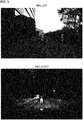
- Fig. 3 is a diagram showing an example of images to be used for the training of the conversion unit 42.
- Fig. 3 shows an image IMG_DAY of a scene acquired in the daytime and an image IMG_NIGHT of the same scene acquired in the nighttime.
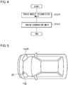
- Fig. 4 is a flowchart showing the training operation of the processing unit 40.
- the object recognition unit 44 is trained with the standard environment image IMG_DAY acquired in a predetermined standard environment (daytime environment) as the learning data (S100).
- the conversion unit 42 is trained using a set of the standard environment images (e.g., IMG_DAY) acquired in a standard environment and an actual environment image (e.g., IMG_NIGHT) acquired in an environment that differs from the standard environment. (S102).
- the above is the configuration of the object identification system 10.
- the object identification system 10 allows the object recognition unit 44 trained in the standard environment to provide high-precision object recognition based on an image acquired in an actual environment that differs from a standard environment.
- such an arrangement requires the object recognition unit 44 to be trained using only images acquired in the daytime without using images acquired in the nighttime (or using only a reduced number of such images acquired in the nighttime). This allows the costs required for the training to be dramatically reduced.
- FIG. 5 is a block diagram showing an automobile including the object identification system 10.
- An automobile 100 includes a headlamps 102L and 102R. From among the components of the object identification system 10, at least the camera 20 is built into at least one of the headlamps 102L and 102R. Each headlamp 102 is positioned at a frontmost end of the vehicle body, which is most advantageous as a position where the camera 20 is to be installed for detecting an object in the vicinity.
- the processing unit 40 may be built into the headlamp 102. Also, the processing unit 40 may be provided to the vehicle side. For example, from among the components of the processing unit 40, the conversion unit 42 that generates the second image IMG2 may be configured as an internal component of the headlamp 102. Also, the object recognition unit 44 may be mounted on the vehicle side.
- Fig. 6 is a block diagram showing an automotive lamp 200 including the object identification system 10.
- the automotive lamp 200 includes a light source 202, a lighting circuit 204, and an optical system 206. Furthermore, the automotive lamp 200 is provided with the camera 20 and the processing unit 40.
- the information with respect to the object OBJ detected by the processing unit 40 is transmitted to the in-vehicle ECU 104.
- the in-vehicle ECU may support autonomous driving based on the information thus transmitted.
- the information with respect to the object OBJ detected by the processing unit 40 may be used to support the light distribution control operation of the automotive lamp 200.
- the lamp ECU 208 generates a suitable light distribution pattern based on the information with respect to the kind of the object OBJ and the position thereof thus generated by the processing unit 40.
- the lighting circuit 204 and the optical system 206 operate so as to provide the light distribution pattern generated by the lamp ECU 208.
- the conversion unit 42 may convert the first image IMG1 so as to reduce the effect of such image distortion.
- the neural network of the conversion unit 42 may be optimized so as to improve the recognition rate with reference to the recognition rate of the object recognition unit 44 as a parameter.
- a past frame generated as a frame consecutive to the first image IMG1 may be input to the conversion unit 42 so as to generate the second image IMG2.
- this allows the conversion unit 42 to support conversion processing based on features that change over time.
- a TOF camera or LiDAR may be employed instead of the camera 20, a TOF camera or LiDAR may be employed.
- the output data of the LiDAR or TOF camera may be handled as image data with the distance as the pixel value.
- the conversion unit 42 converts the output data of the distance measurement sensor into intermediate data as acquired in an environment (clear weather or cloudy weather) in which the learning data used for the training of the object recognition unit 44 was acquired. This allows the identification rate to be improved.
- the processing unit 40 may be configured of only a hardware component using an FPGA, a dedicated Application Specific Integrated Circuit (ASIC), or the like.
- the present invention is not restricted to such an application.
- the object identification system 10 may be fixedly installed on transportation infrastructure such as a traffic light, traffic sign, or the like. That is to say, the present invention is applicable to a fixed-point observation application.
- the present invention relates to an object identification system.
- object identification system 10 object identification system, 20 camera, 40 processing device, 42 conversion unit, 44 object identification unit, IMG1 first image, IMG2 second image, 100 automobile, 102 headlamp, 104 in-vehicle ECU, 200 automotive lamp, 202 light source, 204 lighting circuit, 206 optical system, 208 lamp ECU.
Landscapes
- Engineering & Computer Science (AREA)
- Theoretical Computer Science (AREA)
- Computer Vision & Pattern Recognition (AREA)
- General Physics & Mathematics (AREA)
- Physics & Mathematics (AREA)
- Multimedia (AREA)
- Evolutionary Computation (AREA)
- Artificial Intelligence (AREA)
- Data Mining & Analysis (AREA)
- Medical Informatics (AREA)
- Software Systems (AREA)
- Databases & Information Systems (AREA)
- Computing Systems (AREA)
- Health & Medical Sciences (AREA)
- General Health & Medical Sciences (AREA)
- Mechanical Engineering (AREA)
- Life Sciences & Earth Sciences (AREA)
- Bioinformatics & Computational Biology (AREA)
- Evolutionary Biology (AREA)
- General Engineering & Computer Science (AREA)
- Bioinformatics & Cheminformatics (AREA)
- Image Analysis (AREA)
- Image Processing (AREA)
- Signal Processing (AREA)
Abstract
Description
- The present invention relates to an object identification system.
- Object recognition is a very important architecture in autonomous driving. An object recognition system is configured including a sensor and a processing device configured as a neural network that processes the output of the sensor. Examples of candidates for such a sensor include cameras, Light Detection and Ranging, Laser Imaging Detection and Ranging (LiDAR), millimeter-wave radar, ultrasonic sonar, and so forth. From among such sensor candidates, a high-resolution camera is commercially available for the lowest cost. Such cameras have been becoming popular for mounting on a vehicle.
- The processing device for processing an output image of a camera is configured as a convolutional neural network (CNN). The CNN is subjected to learning (training) using images acquired for various scenes.
- Japanese Patent Application Laid Open No.
2017-56935 - Japanese Patent Application Laid Open No.
2009-98023 - An in-vehicle object recognition system is required to operate even in the nighttime with the same precision as that in the daytime. However, in the nighttime, sunlight cannot be used. Instead, the camera acquires an image using the reflected light from the headlamps of the user's vehicle. Accordingly, an object at a shorter distance from the user's vehicle appears brighter, and an object at a longer distance appears darker, which results in the acquisition of an image that is completely different from an image that is acquired in the daytime. Furthermore, in the nighttime, automobiles have headlamps and taillamps in the lighting-on state, leading to features that differ from those in the daytime.
- In a case in which only images acquired in a daytime scene are used as the learning data, this leads to a degraded identification rate for an object included in an image acquired in a nighttime scene. In a case in which, in addition to using images acquired in the daytime, images acquired in a nighttime scene are used as the learning data, such a problem is mitigated to some extent. However, such an arrangement requires image data acquired in the nighttime, leading to an increase in costs required for the training. In addition, it cannot be anticipated to greatly improve the identification rate with respect to a distant object which is reached by only a small amount of light.
- The present invention has been made in order to solve such a problem. Accordingly, it is an exemplary purpose of an embodiment of the present invention to provide an object recognition system that provides a high identification rate in various kinds of scenes, a processing device thereof, and a learning method.
- An embodiment of the present invention relates to a processing device structured to recognize an object based on image data. The processing device includes: an object recognition unit structured to identify an object based on the image data; and a conversion unit structured as a neural network provided as an upstream stage of the object recognition unit, and structured to convert a first image acquired by a camera into a second image, and to input the second image to the object recognition unit.
- Another embodiment of the present invention relates to a processing device structured to recognize an object based on a sensor output acquired by a sensor. The processing device includes: a conversion unit structured as a neural network, and structured to convert the sensor output to intermediate data; and an object recognition unit structured to identify an object based on the intermediate data. The conversion unit converts the sensor output into the intermediate data as acquired in the same environment as that in which learning data used for training of the object recognition unit was acquired.
- With the present invention, high identification performance can be provided for various kinds of scenes.
-
-
Fig. 1 is a diagram showing an object identification system according to an embodiment; -
Fig. 2 is a diagram for explaining conversion processing supported by a conversion unit; -
Fig. 3 is a diagram showing an example of an image used for training of the conversion unit; -
Fig. 4 is a flowchart showing a learning operation of a processing device; -
Fig. 5 is a block diagram showing an automobile including the object identification system; and -
Fig. 6 is a block diagram showing an automotive lamp including the object identification system. - An embodiment disclosed in the present specification relates to a processing device. The processing device is structured to recognize an object based on image data. The processing device includes: an object recognition unit structured to identify an object based on the image data; and a conversion unit structured as a neural network provided as an upstream stage of the object recognition unit, and structured to convert a first image acquired by a camera into a second image, and to input the second image to the object recognition unit. By providing such an image having shades suitable as the input of the object recognition unit, this arrangement allows the identification rate to be improved.
- Also, the second image may be obtained by correcting the shades of the first image such that they are an approximation of learning data used for training of the object recognition unit. In a case in which such an image that is an approximation of the learning data is input to the object recognition unit, this arrangement allows the identification rate to be improved.
- In the training of the neural network of the conversion unit, the conversion unit may be trained with reference to the recognition rate of the object recognition unit so as to improve the recognition rate.
- Also, the second image may be generated as an image of the same scene as that of the first image, as acquired in the same environment as an environment in which the learning data used for the training of the object recognition unit was acquired.
- Also, the learning data may be acquired in daytime. Also, the conversion unit may convert a first image acquired in nighttime into a second image as acquired in daytime.
- Also, the conversion unit may receive multiple consecutive frames as input. In a case in which multiple consecutive frames are input, this arrangement allows the conversion unit to provide conversion processing based on features that change over time.
- Another embodiment of the present invention relates to a processing device structured to recognize an object based on the sensor output acquired by a sensor. The sensor may be configured as a distant measurement sensor (three-dimensional sensor) such as a LiDAR, TOF sensor, or the like. The processing device includes: a conversion unit structured as a neural network, and structured to convert the sensor output to intermediate data; and an object recognition unit structured to identify an object based on the intermediate data. The conversion unit converts the sensor output into the intermediate data as acquired in the same environment as that in which learning data used for training of the object recognition unit was acquired. For example, rainy weather or dense fog degrades the precision of the distance measurement sensor. The conversion unit compensates for the degraded precision. That is to say, the conversion unit supplies intermediate data as acquired in clear weather to the object recognition unit, thereby providing an improved identification rate.
- Description will be made below regarding the present invention based on preferred embodiments with reference to the drawings. The same or similar components, members, and processes are denoted by the same reference numerals, and redundant description thereof will be omitted as appropriate. The embodiments have been described for exemplary purposes only, and are by no means intended to restrict the present invention. Also, it is not necessarily essential for the present invention that all the features or a combination thereof be provided as described in the embodiments.
-
Fig. 1 is a diagram showing anobject identification system 10 according to an embodiment. Theobject identification system 10 is mounted on a vehicle as described later, and can be used for autonomous driving or a light distribution control operation of headlamps. However, the usage is not restricted. At least a part of the following description of the present embodiment will be made assuming that theobject identification system 10 is mounted on a vehicle. - The
object identification system 10 includes acamera 20 and aprocessing unit 40. Thecamera 20 is configured as an image sensor such as a Complementary Metal Oxide Semiconductor (CMOS) sensor, a Charge Coupled Device (CCD), or the like. Thecamera 20 outputs image data (first image) IMG1 at a predetermined frame rate. - The
processing unit 40 recognizes an object based on the image data IMG1. Specifically, theprocessing unit 40 judges the position and the category of an object included in the image data IMG1. Theprocessing unit 40 is configured as a combination of a processor (hardware component) such as a Central Processing Unit (CPU), Graphics Processing Unit (GPU), microcontroller, or the like, and a software program to be executed by the processor (hardware component). Also, theprocessing unit 40 may be configured as a combination of multiple processors. For example, examples of the category of the object include a pedestrian, bicycle, automobile, pole, and the like. Regarding a pedestrian, a pedestrian as viewed from the front, a pedestrian as viewed from the rear, and a pedestrian as viewed from the side may be defined as the same category of object. The same can be said of an automobile and bicycle. - The
processing unit 40 includes aconversion unit 42 and anobject recognition unit 44. Theobject recognition unit 44 employs an algorithm for a convolutional neural network using deep learning techniques. As such an algorithm, FasterRCNN may be employed. However, the present invention is not restricted to such an arrangement. Examples of algorithms that can be employed include You Only Look Once (YOLO), Single Shot MultiBox Detector (SSD), Region-based Convolutional Neural Network (R-CNN), Spatial Pyramid Pooling (SPPnet), Mask R-CNN, etc. Also, other algorithms that will be developed in the future may be employed. - The
conversion unit 42 is configured as a neural network provided as an upstream stage (previous stage) of theobject recognition unit 44. Theconversion unit 42 converts the first image IMG1 acquired by thecamera 20 into a second image IMG2, and inputs the second image IMG2 to theobject recognition unit 44. - Description will be made regarding the conversion supported by the
conversion unit 42.Fig. 2 is a diagram for explaining the conversion processing supported by theconversion unit 42. Theobject recognition unit 44 is trained using the image data IMG3 (learning data) acquired under a given environment (which is referred to as a "standard environment"). Typically, as the learning data IMG3, images of various scenes (urban area, highway, clear weather, cloudy weather, rainy weather) acquired in daytime are used. In this example, as the standard environment, the daytime environment is employed. - However, in some cases, there is a large difference between the standard environment and an environment (which will be referred to as an "actual environment") in which the second image IMG2 is acquired. Most typical examples thereof include a case in which the actual environment is a nighttime environment. In this case, there is a large difference between the second image IMG2 and the learning data IMG3. The
conversion unit 42 converts the first image IMG1 into the second image IMG2 so as to reduce the difference between them. The second image IMG2 thus converted is an approximation of the learning data IMG3. More specifically, theconversion unit 42 corrects the first image IMG1 such that its shades approximate those of the learning data IMG3, so as to generate the second image IMG2. - That is to say, the second image IMG2 becomes an approximation of an image of the same scene as that of the first image IMG1, as acquired in the standard environment in which the learning data IMG3 used in the training of the
object recognition unit 44 was acquired. Description will be made below regarding an example with the daytime environment as the standard environment and with the nighttime environment as the actual environment. - Examples of known related techniques include a technique for converting a monochrome image into a color image using the deep network technique (S. Iizuka, E. Simo-Serra, H. Ishikawa, "Automatic Coloring of Monochrome Images Using Learning of Global Features and Local Features Using Deep Networks", [online], Internet URL:http://hi.cs.waseda.ac.jp/∼iizuka/projects/colorization/j a/). The
conversion unit 42 employs a somewhat simpler mechanism as compared with the related technique described above. That is to say, theconversion unit 42 is configured to adjust the shades (contrast or brightness levels) without maintaining the color so as to reproduce the image as acquired in the daytime. Theconversion unit 42 having such a function can be designed using known algorithms, which will be clearly understood by those skilled in this art. - The
conversion unit 42 may adjust the brightness or contrast for each pixel, for each area, or for the entire area in a uniform manner. -
Fig. 3 is a diagram showing an example of images to be used for the training of theconversion unit 42.Fig. 3 shows an image IMG_DAY of a scene acquired in the daytime and an image IMG_NIGHT of the same scene acquired in the nighttime. By inputting a great number of such pairs of two images to theconversion unit 42, such an arrangement is capable of constructing a neural network that is capable of converting an image acquired in the nighttime into an image as acquired in the daytime. -
Fig. 4 is a flowchart showing the training operation of theprocessing unit 40. Theobject recognition unit 44 is trained with the standard environment image IMG_DAY acquired in a predetermined standard environment (daytime environment) as the learning data (S100). Furthermore, theconversion unit 42 is trained using a set of the standard environment images (e.g., IMG_DAY) acquired in a standard environment and an actual environment image (e.g., IMG_NIGHT) acquired in an environment that differs from the standard environment. (S102). - The above is the configuration of the
object identification system 10. Theobject identification system 10 allows theobject recognition unit 44 trained in the standard environment to provide high-precision object recognition based on an image acquired in an actual environment that differs from a standard environment. - For example, such an arrangement requires the
object recognition unit 44 to be trained using only images acquired in the daytime without using images acquired in the nighttime (or using only a reduced number of such images acquired in the nighttime). This allows the costs required for the training to be dramatically reduced. -
Fig. 5 is a block diagram showing an automobile including theobject identification system 10. Anautomobile 100 includes aheadlamps 102L and 102R. From among the components of theobject identification system 10, at least thecamera 20 is built into at least one of theheadlamps 102L and 102R. Eachheadlamp 102 is positioned at a frontmost end of the vehicle body, which is most advantageous as a position where thecamera 20 is to be installed for detecting an object in the vicinity. Theprocessing unit 40 may be built into theheadlamp 102. Also, theprocessing unit 40 may be provided to the vehicle side. For example, from among the components of theprocessing unit 40, theconversion unit 42 that generates the second image IMG2 may be configured as an internal component of theheadlamp 102. Also, theobject recognition unit 44 may be mounted on the vehicle side. -
Fig. 6 is a block diagram showing anautomotive lamp 200 including theobject identification system 10. Theautomotive lamp 200 includes alight source 202, alighting circuit 204, and anoptical system 206. Furthermore, theautomotive lamp 200 is provided with thecamera 20 and theprocessing unit 40. The information with respect to the object OBJ detected by theprocessing unit 40 is transmitted to the in-vehicle ECU 104. The in-vehicle ECU may support autonomous driving based on the information thus transmitted. - Also, the information with respect to the object OBJ detected by the
processing unit 40 may be used to support the light distribution control operation of theautomotive lamp 200. Specifically, thelamp ECU 208 generates a suitable light distribution pattern based on the information with respect to the kind of the object OBJ and the position thereof thus generated by theprocessing unit 40. Thelighting circuit 204 and theoptical system 206 operate so as to provide the light distribution pattern generated by thelamp ECU 208. - Description has been made above regarding the present invention with reference to the embodiments. The above-described embodiments have been described for exemplary purposes only, and are by no means intended to be interpreted restrictively. Rather, it can be readily conceived by those skilled in this art that various modifications may be made by making various combinations of the aforementioned components or processes, which are also encompassed in the technical scope of the present invention. Description will be made below regarding such modifications.
- Description has been made in the embodiment regarding an example of a difference in the environment between the daytime and the nighttime. However, the present invention is not restricted to such an example. In a case in which there is a large difference in the angle of view, field of view, line of sight, image distortion, or the like, between an image acquisition system including a camera (reference camera) used to acquire the learning data and the
camera 20 mounted on theobject identification system 10, such a difference can be regarded as a difference in the environment. In this case, the first image IMG1 acquired by thecamera 20 may be converted into a second image IMG2 such that it becomes an approximation of an image as acquired by the reference camera. In this case, instead of shades, theconversion unit 42 corrects the shape of an image. - For example, in a case in which the
camera 20 is built into a headlamp, in some cases, image distortion occurs due to an outer lens. On the other hand, the camera that acquires the learning data does not involve such image distortion. In this case, theconversion unit 42 may convert the first image IMG1 so as to reduce the effect of such image distortion. - With the embodiment, in the training of the neural network of the
conversion unit 42, the neural network of theconversion unit 42 may be optimized so as to improve the recognition rate with reference to the recognition rate of theobject recognition unit 44 as a parameter. - In addition to the first image IMG1 generated as a current frame, a past frame generated as a frame consecutive to the first image IMG1 may be input to the
conversion unit 42 so as to generate the second image IMG2. By inputting multiple consecutive frames, this allows theconversion unit 42 to support conversion processing based on features that change over time. - Instead of the
camera 20, a TOF camera or LiDAR may be employed. In this case, the output data of the LiDAR or TOF camera may be handled as image data with the distance as the pixel value. There is a difference in the output data of the distance measurement sensor (three-dimensional sensor) between rainfall, snowfall, and dense fog compared to cloudy weather or clear weather. In order to solve such a problem, theconversion unit 42 converts the output data of the distance measurement sensor into intermediate data as acquired in an environment (clear weather or cloudy weather) in which the learning data used for the training of theobject recognition unit 44 was acquired. This allows the identification rate to be improved. - The
processing unit 40 may be configured of only a hardware component using an FPGA, a dedicated Application Specific Integrated Circuit (ASIC), or the like. - Description has been made in the embodiment regarding the in-vehicle
object identification system 10. However, the present invention is not restricted to such an application. For example, theobject identification system 10 may be fixedly installed on transportation infrastructure such as a traffic light, traffic sign, or the like. That is to say, the present invention is applicable to a fixed-point observation application. - Description has been made regarding the present invention with reference to the embodiments using specific terms. However, the above-described embodiments show only an aspect of the mechanisms and applications of the present invention. Rather, various modifications and various changes in the layout can be made without departing from the spirit and scope of the present invention defined in appended claims.
- The present invention relates to an object identification system.
- 10 object identification system, 20 camera, 40 processing device, 42 conversion unit, 44 object identification unit, IMG1 first image, IMG2 second image, 100 automobile, 102 headlamp, 104 in-vehicle ECU, 200 automotive lamp, 202 light source, 204 lighting circuit, 206 optical system, 208 lamp ECU.
Claims (11)
- A processing device structured to recognize an object based on image data, comprising:an object recognition unit structured to identify an object based on the image data; anda conversion unit structured as a neural network provided as an upstream stage of the object recognition unit, and structured to convert a first image acquired by a camera into a second image, and to input the second image to the object recognition unit.
- The processing device according to claim 1, wherein the second image is obtained by correcting shades of the first image such that they are an approximation of learning data used for training of the object recognition unit.
- The processing device according to claim 1 or 2,
wherein the second image of the same scene as that of the first image is generated as an image as acquired in the same environment as an environment in which the learning data used for the training of the object recognition unit was acquired. - The processing device according to claim 3, wherein the learning data is acquired in daytime,
and wherein the conversion unit converts the first image acquired in nighttime into the second image as acquired in daytime. - The processing device according to any one of claims 1 through 4, wherein, in the training of the conversion unit, the neural network of the conversion unit is optimized with reference to an identification rate of the object recognition unit so as to improve the identification rate.
- The processing device according to any one of claims 1 through 5, wherein the conversion unit receives a plurality of consecutive frames as input.
- An object identification system comprising:a camera; andthe processing device according to any one of claims 1 through 6.
- An automotive lamp comprising the object identification system according to claim 7.
- An automobile comprising:a camera built into a headlamp; andthe processing device according to any one of claims 1 through 6.
- A processing device structured to recognize an object based on a sensor output acquired by a sensor, comprising:a conversion unit structured as a neural network, and structured to convert the sensor output to intermediate data; andan object recognition unit structured to identify an object based on the intermediate data,wherein the conversion unit converts the sensor output into the intermediate data as acquired in the same environment as that in which learning data used for training of the object recognition unit was acquired.
- A learning method for a processing device structured to recognize an object based on image data acquired by a camera, wherein the processing device comprises:a conversion unit structured to convert the image data acquired by the camera; andan object recognition unit structured to process image data processed by the conversion unit, and to identify the object,and wherein the learning method comprises:training the object recognition unit using an image acquired in a predetermined environment as learning data; andtraining the conversion unit using a set of an image acquired in the predetermined environment and an image acquired in an environment that differs from the predetermined environment.
Applications Claiming Priority (2)
| Application Number | Priority Date | Filing Date | Title |
|---|---|---|---|
| JP2018073354 | 2018-04-05 | ||
| PCT/JP2019/014890 WO2019194256A1 (en) | 2018-04-05 | 2019-04-03 | Operation processing device, object identifying system, learning method, automobile, and lighting appliance for vehicle |
Publications (2)
| Publication Number | Publication Date |
|---|---|
| EP3779872A1 true EP3779872A1 (en) | 2021-02-17 |
| EP3779872A4 EP3779872A4 (en) | 2021-05-19 |
Family
ID=68100544
Family Applications (1)
| Application Number | Title | Priority Date | Filing Date |
|---|---|---|---|
| EP19781869.3A Withdrawn EP3779872A4 (en) | 2018-04-05 | 2019-04-03 | WORK PROCESSING DEVICE, OBJECT IDENTIFICATION SYSTEM, LEARNING PROCEDURE, AUTOMOTIVE AND LIGHTING DEVICE FOR VEHICLE |
Country Status (5)
| Country | Link |
|---|---|
| US (1) | US11676394B2 (en) |
| EP (1) | EP3779872A4 (en) |
| JP (1) | JP7268001B2 (en) |
| CN (1) | CN112005245A (en) |
| WO (1) | WO2019194256A1 (en) |
Families Citing this family (13)
| Publication number | Priority date | Publication date | Assignee | Title |
|---|---|---|---|---|
| JP6642474B2 (en) * | 2017-02-13 | 2020-02-05 | オムロン株式会社 | State determination device, learning device, state determination method, and program |
| CN112005245A (en) * | 2018-04-05 | 2020-11-27 | 株式会社小糸制作所 | Arithmetic processing device, object recognition system, learning method, lamps for automobiles and vehicles |
| KR20210075568A (en) * | 2019-12-13 | 2021-06-23 | 임영한 | Intersection Traffic Signal Utilizing Artificial Intelligence |
| FR3112009B1 (en) * | 2020-06-30 | 2022-10-28 | St Microelectronics Grenoble 2 | Process for converting a digital image |
| US20220122360A1 (en) * | 2020-10-21 | 2022-04-21 | Amarjot Singh | Identification of suspicious individuals during night in public areas using a video brightening network system |
| JP7590734B2 (en) * | 2021-02-26 | 2024-11-27 | 株式会社デンソーテン | Image processing device and image processing method |
| JP7696561B2 (en) * | 2021-04-14 | 2025-06-23 | 成典 田中 | car estimation device |
| EP4350613A4 (en) * | 2021-05-27 | 2025-05-07 | Kyocera Corporation | TRAINED MODEL GENERATION DEVICE, TRAINED MODEL GENERATION METHOD, AND RECOGNITION DEVICE |
| JP7271809B2 (en) * | 2021-05-28 | 2023-05-11 | 京セラ株式会社 | Trained model generation device, trained model generation method, and recognition device |
| FR3124252B1 (en) * | 2021-06-18 | 2023-10-27 | Valeo Vision | Method for detecting an object on a road surface, autonomous driving method and automobile lighting device |
| US11367289B1 (en) * | 2021-07-16 | 2022-06-21 | Motional Ad Llc | Machine learning-based framework for drivable surface annotation |
| US12015855B2 (en) | 2021-11-16 | 2024-06-18 | Samsung Electronics Co., Ltd. | System and method for synthesizing low-light images |
| US20250191351A1 (en) * | 2022-04-06 | 2025-06-12 | Sony Interactive Entertainment Inc. | Information processing system, information processing method, and program |
Family Cites Families (13)
| Publication number | Priority date | Publication date | Assignee | Title |
|---|---|---|---|---|
| JPH05127698A (en) * | 1991-10-30 | 1993-05-25 | Ricoh Co Ltd | Pattern conversion device and image pattern resotration part using neural network |
| JP3885344B2 (en) * | 1998-03-24 | 2007-02-21 | コニカミノルタホールディングス株式会社 | Color data holding method and color management method |
| JP2008105518A (en) * | 2006-10-25 | 2008-05-08 | Calsonic Kansei Corp | Camera built-in lamp |
| JP5115792B2 (en) * | 2007-07-04 | 2013-01-09 | オムロン株式会社 | Image processing apparatus and method, and program |
| JP2009098023A (en) | 2007-10-17 | 2009-05-07 | Toyota Motor Corp | Object detection apparatus and object detection method |
| JP6440303B2 (en) * | 2014-12-02 | 2018-12-19 | エヌ・ティ・ティ・コムウェア株式会社 | Object recognition device, object recognition method, and program |
| CN105260699B (en) * | 2015-09-10 | 2018-06-26 | 百度在线网络技术(北京)有限公司 | A kind of processing method and processing device of lane line data |
| US9576185B1 (en) | 2015-09-14 | 2017-02-21 | Toyota Motor Engineering & Manufacturing North America, Inc. | Classifying objects detected by 3D sensors for autonomous vehicle operation |
| KR20180092778A (en) * | 2017-02-10 | 2018-08-20 | 한국전자통신연구원 | Apparatus for providing sensory effect information, image processing engine, and method thereof |
| KR101818129B1 (en) * | 2017-04-25 | 2018-01-12 | 동국대학교 산학협력단 | Device and method for pedestrian recognition using convolutional neural network |
| CN107767408B (en) * | 2017-11-09 | 2021-03-12 | 京东方科技集团股份有限公司 | Image processing method, processing device and processing device |
| US10984286B2 (en) * | 2018-02-02 | 2021-04-20 | Nvidia Corporation | Domain stylization using a neural network model |
| CN112005245A (en) * | 2018-04-05 | 2020-11-27 | 株式会社小糸制作所 | Arithmetic processing device, object recognition system, learning method, lamps for automobiles and vehicles |
-
2019
- 2019-04-03 CN CN201980023552.5A patent/CN112005245A/en active Pending
- 2019-04-03 WO PCT/JP2019/014890 patent/WO2019194256A1/en not_active Ceased
- 2019-04-03 JP JP2020512308A patent/JP7268001B2/en active Active
- 2019-04-03 EP EP19781869.3A patent/EP3779872A4/en not_active Withdrawn
-
2020
- 2020-10-02 US US17/061,662 patent/US11676394B2/en active Active
Also Published As
| Publication number | Publication date |
|---|---|
| WO2019194256A1 (en) | 2019-10-10 |
| CN112005245A (en) | 2020-11-27 |
| JP7268001B2 (en) | 2023-05-02 |
| US20210027102A1 (en) | 2021-01-28 |
| JPWO2019194256A1 (en) | 2021-04-01 |
| US11676394B2 (en) | 2023-06-13 |
| EP3779872A4 (en) | 2021-05-19 |
Similar Documents
| Publication | Publication Date | Title |
|---|---|---|
| US11676394B2 (en) | Processing device for conversion of images | |
| JP6176028B2 (en) | Vehicle control system, image sensor | |
| CN110412599B (en) | Distance measurement processing device, distance measurement module and distance measurement processing method | |
| JP7830407B2 (en) | Electronic devices, mobile devices, imaging devices, and control methods, programs, and storage media for electronic devices. | |
| CN103213540B (en) | Vehicle driving environment recognition apparatus | |
| EP2642429B1 (en) | Multi-lens camera system and range-finding method executed by the multi-lens camera system | |
| US10634317B2 (en) | Dynamic control of vehicle lamps during maneuvers | |
| US12488593B2 (en) | Correction of images from a panoramic-view camera system in the case of rain, incident light and contamination | |
| JP7701986B2 (en) | Data-driven dynamically reconstructed disparity maps | |
| US11029150B2 (en) | Object distance detection device | |
| JP6209825B2 (en) | Parallax detection device and parallax detection method | |
| US20200118280A1 (en) | Image Processing Device | |
| JP6789151B2 (en) | Camera devices, detectors, detection systems and mobiles | |
| US20110007162A1 (en) | Method and device for image detection for motor vehicles | |
| CN113632450B (en) | Imaging system and image processing apparatus | |
| WO2019058755A1 (en) | Object distance detection device | |
| KR20230048429A (en) | A system to prevent accidents caused by wild animal crossing at dusk and at night | |
| JP4900377B2 (en) | Image processing device | |
| CN117528264A (en) | Parameter adjustment method, device and intelligent driving system | |
| EP3562145A1 (en) | Method and apparatus for operating an advanced driver assistance system of a vehicle | |
| EP4502659A1 (en) | Range-finding device and range-finding method | |
| JP7253693B2 (en) | Image processing device | |
| CN120747919A (en) | Obstacle recognition method based on multimode fusion |
Legal Events
| Date | Code | Title | Description |
|---|---|---|---|
| STAA | Information on the status of an ep patent application or granted ep patent |
Free format text: STATUS: THE INTERNATIONAL PUBLICATION HAS BEEN MADE |
|
| PUAI | Public reference made under article 153(3) epc to a published international application that has entered the european phase |
Free format text: ORIGINAL CODE: 0009012 |
|
| STAA | Information on the status of an ep patent application or granted ep patent |
Free format text: STATUS: REQUEST FOR EXAMINATION WAS MADE |
|
| 17P | Request for examination filed |
Effective date: 20200925 |
|
| AK | Designated contracting states |
Kind code of ref document: A1 Designated state(s): AL AT BE BG CH CY CZ DE DK EE ES FI FR GB GR HR HU IE IS IT LI LT LU LV MC MK MT NL NO PL PT RO RS SE SI SK SM TR |
|
| AX | Request for extension of the european patent |
Extension state: BA ME |
|
| A4 | Supplementary search report drawn up and despatched |
Effective date: 20210416 |
|
| RIC1 | Information provided on ipc code assigned before grant |
Ipc: G06T 7/00 20170101AFI20210412BHEP Ipc: G06K 9/00 20060101ALI20210412BHEP Ipc: G06K 9/62 20060101ALI20210412BHEP |
|
| RIC1 | Information provided on ipc code assigned before grant |
Ipc: G06T 7/00 20170101AFI20210426BHEP Ipc: G06K 9/00 20060101ALI20210426BHEP Ipc: G06K 9/62 20060101ALI20210426BHEP |
|
| DAV | Request for validation of the european patent (deleted) | ||
| DAX | Request for extension of the european patent (deleted) | ||
| STAA | Information on the status of an ep patent application or granted ep patent |
Free format text: STATUS: THE APPLICATION IS DEEMED TO BE WITHDRAWN |
|
| 18D | Application deemed to be withdrawn |
Effective date: 20211116 |