EP3779420A1 - Sensor, detecting method, and sensor manufacturing method - Google Patents
Sensor, detecting method, and sensor manufacturing method Download PDFInfo
- Publication number
- EP3779420A1 EP3779420A1 EP19775806.3A EP19775806A EP3779420A1 EP 3779420 A1 EP3779420 A1 EP 3779420A1 EP 19775806 A EP19775806 A EP 19775806A EP 3779420 A1 EP3779420 A1 EP 3779420A1
- Authority
- EP
- European Patent Office
- Prior art keywords
- supported
- sensor
- volume change
- storage space
- volume
- Prior art date
- Legal status (The legal status is an assumption and is not a legal conclusion. Google has not performed a legal analysis and makes no representation as to the accuracy of the status listed.)
- Granted
Links
Images














Classifications
-
- G—PHYSICS
- G01—MEASURING; TESTING
- G01F—MEASURING VOLUME, VOLUME FLOW, MASS FLOW OR LIQUID LEVEL; METERING BY VOLUME
- G01F22/00—Methods or apparatus for measuring volume of fluids or fluent solid material, not otherwise provided for
- G01F22/02—Methods or apparatus for measuring volume of fluids or fluent solid material, not otherwise provided for involving measurement of pressure
-
- G—PHYSICS
- G01—MEASURING; TESTING
- G01L—MEASURING FORCE, STRESS, TORQUE, WORK, MECHANICAL POWER, MECHANICAL EFFICIENCY, OR FLUID PRESSURE
- G01L1/00—Measuring force or stress, in general
- G01L1/18—Measuring force or stress, in general using properties of piezo-resistive materials, i.e. materials of which the ohmic resistance varies according to changes in magnitude or direction of force applied to the material
-
- G—PHYSICS
- G01—MEASURING; TESTING
- G01G—WEIGHING
- G01G3/00—Weighing apparatus characterised by the use of elastically-deformable members, e.g. spring balances
- G01G3/12—Weighing apparatus characterised by the use of elastically-deformable members, e.g. spring balances wherein the weighing element is in the form of a solid body stressed by pressure or tension during weighing
- G01G3/13—Weighing apparatus characterised by the use of elastically-deformable members, e.g. spring balances wherein the weighing element is in the form of a solid body stressed by pressure or tension during weighing having piezoelectric or piezoresistive properties
-
- G—PHYSICS
- G01—MEASURING; TESTING
- G01G—WEIGHING
- G01G3/00—Weighing apparatus characterised by the use of elastically-deformable members, e.g. spring balances
- G01G3/12—Weighing apparatus characterised by the use of elastically-deformable members, e.g. spring balances wherein the weighing element is in the form of a solid body stressed by pressure or tension during weighing
- G01G3/16—Weighing apparatus characterised by the use of elastically-deformable members, e.g. spring balances wherein the weighing element is in the form of a solid body stressed by pressure or tension during weighing measuring variations of frequency of oscillations of the body
-
- G—PHYSICS
- G01—MEASURING; TESTING
- G01K—MEASURING TEMPERATURE; MEASURING QUANTITY OF HEAT; THERMALLY-SENSITIVE ELEMENTS NOT OTHERWISE PROVIDED FOR
- G01K11/00—Measuring temperature based upon physical or chemical changes not covered by groups G01K3/00, G01K5/00, G01K7/00 or G01K9/00
- G01K11/06—Measuring temperature based upon physical or chemical changes not covered by groups G01K3/00, G01K5/00, G01K7/00 or G01K9/00 using melting, freezing, or softening
-
- G—PHYSICS
- G01—MEASURING; TESTING
- G01K—MEASURING TEMPERATURE; MEASURING QUANTITY OF HEAT; THERMALLY-SENSITIVE ELEMENTS NOT OTHERWISE PROVIDED FOR
- G01K5/00—Measuring temperature based on the expansion or contraction of a material
- G01K5/48—Measuring temperature based on the expansion or contraction of a material the material being a solid
-
- G—PHYSICS
- G01—MEASURING; TESTING
- G01K—MEASURING TEMPERATURE; MEASURING QUANTITY OF HEAT; THERMALLY-SENSITIVE ELEMENTS NOT OTHERWISE PROVIDED FOR
- G01K5/00—Measuring temperature based on the expansion or contraction of a material
- G01K5/48—Measuring temperature based on the expansion or contraction of a material the material being a solid
- G01K5/56—Measuring temperature based on the expansion or contraction of a material the material being a solid constrained so that expansion or contraction causes a deformation of the solid
- G01K5/62—Measuring temperature based on the expansion or contraction of a material the material being a solid constrained so that expansion or contraction causes a deformation of the solid the solid body being formed of compounded strips or plates, e.g. bimetallic strip
- G01K5/70—Measuring temperature based on the expansion or contraction of a material the material being a solid constrained so that expansion or contraction causes a deformation of the solid the solid body being formed of compounded strips or plates, e.g. bimetallic strip specially adapted for indicating or recording
- G01K5/72—Measuring temperature based on the expansion or contraction of a material the material being a solid constrained so that expansion or contraction causes a deformation of the solid the solid body being formed of compounded strips or plates, e.g. bimetallic strip specially adapted for indicating or recording with electric transmission means for final indication
-
- G—PHYSICS
- G01—MEASURING; TESTING
- G01L—MEASURING FORCE, STRESS, TORQUE, WORK, MECHANICAL POWER, MECHANICAL EFFICIENCY, OR FLUID PRESSURE
- G01L1/00—Measuring force or stress, in general
- G01L1/18—Measuring force or stress, in general using properties of piezo-resistive materials, i.e. materials of which the ohmic resistance varies according to changes in magnitude or direction of force applied to the material
- G01L1/183—Measuring force or stress, in general using properties of piezo-resistive materials, i.e. materials of which the ohmic resistance varies according to changes in magnitude or direction of force applied to the material by measuring variations of frequency of vibrating piezo-resistive material
-
- G—PHYSICS
- G01—MEASURING; TESTING
- G01N—INVESTIGATING OR ANALYSING MATERIALS BY DETERMINING THEIR CHEMICAL OR PHYSICAL PROPERTIES
- G01N27/00—Investigating or analysing materials by the use of electric, electrochemical, or magnetic means
-
- G—PHYSICS
- G01—MEASURING; TESTING
- G01N—INVESTIGATING OR ANALYSING MATERIALS BY DETERMINING THEIR CHEMICAL OR PHYSICAL PROPERTIES
- G01N5/00—Analysing materials by weighing, e.g. weighing small particles separated from a gas or liquid
- G01N5/02—Analysing materials by weighing, e.g. weighing small particles separated from a gas or liquid by absorbing or adsorbing components of a material and determining change of weight of the adsorbent, e.g. determining moisture content
-
- G—PHYSICS
- G01—MEASURING; TESTING
- G01J—MEASUREMENT OF INTENSITY, VELOCITY, SPECTRAL CONTENT, POLARISATION, PHASE OR PULSE CHARACTERISTICS OF INFRARED, VISIBLE OR ULTRAVIOLET LIGHT; COLORIMETRY; RADIATION PYROMETRY
- G01J5/00—Radiation pyrometry, e.g. infrared or optical thermometry
- G01J5/38—Radiation pyrometry, e.g. infrared or optical thermometry using extension or expansion of solids or fluids
Definitions
- the present invention relates to a sensor, a detection method, and a sensor manufacturing method.
- One of the known sensors has a volume change body, whose volume changes depending on the amount of a target (for example, molecules that constitute a gas or a liquid), and detects stress caused by the change in the volume of the volume change body.
- a target for example, molecules that constitute a gas or a liquid
- the sensor described in Patent Literature 1 has a body member, the volume change body, and a detection member.
- the body member has a flat plate-like shape.
- the volume change body changes in the volume by receiving the target and covers both end faces in the thickness direction of the body member.
- the detection member whose tip is supported, extends from the end of the body member.
- the detection member includes a piezoresistive element and detects the stress caused by the change in the volume of the volume change body.
- Patent Literature 1 International Publication No. WO2013/157581
- the stress in the thickness direction of the body member may be caused by, for example, the variation in the amount of the target received by the volume change body.
- the body member may be bent.
- the change in the volume of the volume change body may not be reflected with high accuracy in the stress occurred in the detection member.
- the sensor may not be able to detect the target with high accuracy.
- An object of the present invention is to detect the target with high accuracy.
- a sensor comprising: a body member that has a flat plate-like shape, a first end in a first direction being supported, and a storage space opening at at least one of end faces in a thickness direction; a volume change body, whose volume changes depending on an amount of a target, that is supported by the body member so that at least a part of the volume change body is stored in the storage space; and a detection member that is in contact with a second end in the first direction of the body member and detects stress caused by the change in the volume of the volume change body.
- a detection method including: changing a volume of a volume change body depending on an amount of a target, the volume change body being supported by a body member so that at least a part of the volume change body is stored in a storage space, the body member having a flat plate-like shape, a first end in a first direction being supported, and the storage space opening at at least one of end faces in a thickness direction; and detecting stress caused by the change in the volume of the volume change body in a detection member that is in contact with a second end in the first direction of the body member.
- a sensor manufacturing method including: forming a storage space in a first member, the first member having a flat plate-like shape and a first end in a first direction being supported, the storage space opening at at least one of end faces in a thickness direction, and providing an element in a second member in contact with a second end in the first direction of the first member, the element detecting stress; and storing at least a part of the volume change body, whose volume changes depending on an amount of a target, in the storage space so as to be supported by the first member.
- the target can be detected with high accuracy.
- a sensor of a first embodiment includes a body member, a volume change body, and a detection member.
- the body member has a flat plate-like shape, a first end in a first direction being supported, and a storage space opening at at least one of both end faces in a thickness direction.
- the volume change body whose volume changes depending on an amount of a target, is supported by the body member so that at least a part of the volume change body is stored in the storage space.
- the detection member is in contact with a second end in the first direction in the body member, and detects stress caused by the change in the volume of the volume change body.
- the occurrence of stress in the thickness direction of the body member can be suppressed even when the volume of the volume change body changes. This can prevent the body member from bending. Therefore, the occurrence of stress in the thickness direction of the body member at the second end can be suppressed. As a result, the change in the volume of the volume change body can be reflected with high accuracy in the stress, which occurs at the second end, in the direction along the body member. In other words, the sensor can detect the target with high accuracy.
- the sensor 1 of the first embodiment will be described using a right-handed orthogonal coordinate system having an x-axis, a y-axis, and a z-axis.
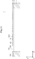
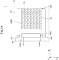
- the same coordinate system is used in Figs. 11 to 14 and Figs. 24 to 37 described later.
- the sensor 1 detects the target.
- the target is molecules that constitute a gas, a liquid, or a solid.
- the target is molecules that constitute a mixture of at least two of a gas, a liquid, and a solid.
- the target is fine particles, temperature, humidity, electromagnetic wave, or the like.
- the x-axis direction, the y-axis direction, and the z-axis direction may be represented as the left-right direction of the sensor 1, the front-back direction of the sensor 1, and the up-down direction of the sensor 1, respectively.
- the positive direction of the x-axis, the negative direction of the x-axis, the positive direction of the y-axis, the negative direction of the y-axis, the positive direction of the z-axis, and the negative direction of the z-axis are the right direction of the sensor 1, the left direction of sensor 1, the front direction of the sensor 1, the back direction of the sensor 1, the up direction of the sensor 1, and the down direction of the sensor 1, respectively.
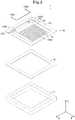
- Fig. 1 is a view of the sensor 1 from the position to right of the sensor 1, in front of the sensor 1, and above the sensor 1 (in other words, right front upper perspective view).
- Fig. 2 is a right front upper perspective view of the sensor 1 in a state where the sensor 1 is disassembled.
- Fig. 3 is a view of the sensor 1 from right side of the sensor 1 (in other words, right side view).
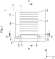
- Fig. 4 is a view of the sensor 1 from above the sensor 1 (in other words, a plan view).
- Fig. 5 is a view of the sensor 1 from below the sensor 1 (in other words, a bottom view).
- Fig. 6 is a view of the cross section of the sensor 1 cut by a plane represented by a VI-VI line in Fig. 4 as viewed in the negative direction of the x-axis.
- Fig. 7 is a view of the cross section of the sensor 1 cut by a plane represented by a VII-VII line in Fig. 4 as viewed in the negative direction of the y-axis.
- the sensor 1 has a pillar-like shape extending in the z-axis direction.
- the cross section of the sensor 1 cut by the plane orthogonal to the z-axis (in other words, an xy-plane) has a square-like shape.
- the cross section of the sensor 1 cut by the xy-plane may have a shape (for example, a circular-like, elliptical-like, or rectangular-like shape) different from the square-like shape.
- the length of a side of the cross section of the sensor 1 cut by the xy-plane is a length of 50 ⁇ m to 5 mm. In this example, the length of a side of the cross section of the sensor 1 cut by the xy-plane is 500 ⁇ m.
- the sensor 1 may be manufactured using a technique called microfabrication or nanofabrication.
- the sensor 1 includes a first layered body 11, a second layered body 12, a third layered body 13, and a volume change body 14.
- the first layered body 11, the second layered body 12, and the third layered body 13 are laminated so as to be arranged in this order in the z-axis direction.
- the second layered body 12 is in contact with the first layered body 11, and the third layered body 13 is in contact with the second layered body 12 at the opposite side of the first layered body 11.
- the second layered body 12 is sandwiched between the first layered body 11 and the third layered body 13.
- the first layered body 11 has a thickness of 0.5 ⁇ m to 50 ⁇ m
- the second layered body 12 has a thickness of 0.05 ⁇ m to 5 ⁇ m
- the third layered body 13 has a thickness of 50 ⁇ m to 5 mm.
- the thickness of the first layered body 11 is 5 ⁇ m
- the thickness of the second layered body 12 is 0.5 ⁇ m
- the thickness of the third layered body 13 is 500 ⁇ m.
- the first layered body 11 is made of silicon. As illustrated in Figs. 1 and 2 , the first layered body 11 has a hollow pillar-like shape that extends in the z-axis direction and opens at both end faces in the z-axis direction.
- the second layered body 12 is made of silicon dioxide. As illustrated in Figs. 1 and 2 , the second layered body 12 has a flat plate-like shape. The second layered body 12 has a hole that opens at both end faces in the z-axis direction of the second layered body 12. In this example, the cross section of the second layered body 12 cut by the xy-plane has the same shape as the cross section of the first layered body 11 cut by the xy-plane.
- the third layered body 13 is made of silicon. As illustrated in Figs. 1 and 2 , the third layered body 13 has a flat plate-like shape. In this example, the exposed surface of the third layered body 13 is covered with an insulator thin film (not illustrated).
- the third layered body 13 includes a frame 131, a body member 132, and a detection member 133.
- the frame 131 has a hole that opens at both end faces in the z-axis direction of the frame 131.
- the cross section of the frame 131 cut by the xy-plane has the same shape as the cross section of the first layered body 11 cut by the xy-plane.
- the body member 132 has a rectangular-like shape having long sides extending in the y-axis direction and short sides extending in the x-axis direction.
- the body member 132 may have a square-like shape.
- the length of the body member 132 in the y-axis direction is shorter than the length of the hole of the frame 131 in the y-axis direction. In this example, the length of the body member 132 in the y-axis direction is 367 ⁇ m.
- the length of the body member 132 in the x-axis direction is shorter than the length of the hole of the frame 131 in the x-axis direction. In this example, the length of the body member 132 in the x-axis direction is 300 ⁇ m. Both ends in the x-axis direction of the body member 132 are separated from the frame 131.
- the body member 132 is in contact with the frame 131 at the first end 1321 in the positive direction of the y-axis of the body member 132.
- the first end 1321 in the positive direction of the y-axis of the body member 132 is supported by the frame 131.
- Both end portions in the x-axis direction of the second end 1322 in the negative direction of the y-axis of the body member 132 are in contact with the frame 131 through the detection member 133.
- the central portion in the x-axis direction of the second end 1322 in the negative direction of the y-axis of the body member 132 is separated from the frame 131.
- the body member 132 has a space formation portion 1323 that forms a storage space that opens at both end faces in the z-axis direction (in other words, the thickness direction of the body member 132) of the body member 132.
- the storage space includes slit-like holes extending in the x-axis direction.
- each hole included in the storage space is a through hole that penetrates the body member 132 in the z-axis direction.
- the holes in the storage space are arranged at equal intervals along the y-axis direction.
- the length in the y-axis direction of each hole included in the storage space is a length of 0.1 ⁇ m to 10 ⁇ m.
- the length in the y-axis direction of each hole included in the storage space is 1 ⁇ m.
- the interval in the y-axis direction between the holes included in the storage space has a length of 0.1 ⁇ m to 10 ⁇ m.
- the interval in the y-axis direction between the holes included in the storage space is 1 ⁇ m.
- the number of the holes included in the storage space is 133. Note that, in Figs. 1 to 7 , the holes included in the storage space are illustrated in an enlarged manner in the y-axis direction. Therefore, in Figs. 1 to 7 , the holes included in the storage space are illustrated in a reduced number manner.
- the length of the slit-like holes included in the storage space in the x-axis direction is 280 ⁇ m.
- the detection member 133 includes a first supported member 1331, a second supported member 1332, a first wiring 1333, and a second wiring 1334.
- the first supported member 1331 has a strip-like shape extending in the y-axis direction.
- the end in the negative direction of the y-axis of the first supported member 1331 is in contact with the frame 131.
- the end in the positive direction of the y-axis of the first supported member 1331 is in contact with the end portion in the negative direction of the x-axis of the second end 1322 of the body member 132.
- the first supported member 1331 extends from the second end 1322 of the body member 132 to the negative direction of the y-axis, and the tip of the first supported member 1331 is supported by the frame 131.
- the width of the first supported member 1331 (in other words, the length of the first supported member 1331 in the x-axis direction) is narrower than the width of the body member 132 (in other words, the length of the body member 132 in the x-axis direction).
- the width of the central portion of the first supported member 1331 in an extension direction (the y-axis direction in this example), in which the first supported member 1331 extends, is narrower than the width of each of the end portions in the extension direction of the first supported member 1331.
- the first supported member 1331 includes a piezoresistive element PZ located in the central portion in the extension direction of the first supported member 1331.
- the piezoresistive element PZ is an element whose electric resistance changes depending on the stress applied to the piezoresistive element PZ.
- the piezoresistive element PZ is an element having a piezoresistive effect.
- the piezoresistive element PZ is embedded in the first supported member 1331 so as to be exposed at the end face in the positive direction of the z-axis of the first supported member 1331.
- the detection member 133 detects the stress transmitted from the body member 132 in the central portion in the extension direction of the first supported member 1331.
- the second supported member 1332 has a strip-like shape extending in the y-axis direction.
- the end in the negative direction of the y-axis of the second supported member 1332 is in contact with the frame 131.
- the end in the positive direction of the y-axis of the second supported member 1332 is in contact with the end portion in the positive direction of the x-axis of the second end 1322 of the body member 132.
- the second supported member 1332 extends from the second end 1322 of the body member 132 to the negative direction of the y-axis, and the tip of the second supported member 1332 is supported by the frame 131.
- the width of the second supported member 1332 (in other words, the length of the second supported member 1332 in the x-axis direction) is narrower than the width of the body member 132.
- the width of the central portion of the second supported member 1332 in an extension direction (the y-axis direction in this example), in which the second supported member 1332 extends, is narrower than the width of each of the end portions of the second supported member 1332 in the extension direction.
- the first wiring 1333 and the second wiring 1334 are made of conductor (aluminum in this example).
- the first wiring 1333 and the second wiring 1334 are laid on the end face in the positive direction of the z-axis of the third layered body 13.
- the thickness of the first wiring 1333 and the second wiring 1334 (in other words, the length in the z-axis direction of the first wiring 1333 and the second wiring 1334) is a thickness of 10 nm to 1 ⁇ m. In this example, the thickness of the first wiring 1333 and the second wiring 1334 is 100 nm.
- a part of the exposed surface of the first wiring 1333 and the second wiring 1334 is covered with an oxide thin film (not illustrated).
- the other part, which is not covered with the oxide thin film, of the exposed surface of the first wiring 1333 and the second wiring 1334 may be used as terminals for connection.
- one end portion of the first wiring 1333 is in contact with the end portion in the negative direction of the y-axis of the piezoresistive element PZ.
- the other end portion of the first wiring 1333 is located at the outer edge of the frame 131.
- the first wiring 1333 extends from the end portion in the negative direction of the y-axis of the piezoresistive element PZ to the outer edge of the frame 131 through the tip of the first supported member 1331 (in other words, the end, which is in contact with the frame 131, of the first supported member 1331). In other words, the first wiring 1333 connects the piezoresistive element PZ and the tip of the first supported member 1331.
- One end portion of the second wiring 1334 is in contact with the end portion in the positive direction of the y-axis of the piezoresistive element PZ.
- the other end portion of the second wiring 1334 is located at the outer edge of frame 131.
- the second wiring 1334 extends from the end portion in the positive direction of the y-axis of the piezoresistive element PZ to the outer edge of the frame 131 through the proximal end (in other words, the end, which is in contact with the body member 132, of the first supported member 1331) of the first supported member 1331, the end portion in the negative direction of the y-axis of the body member 132, and the second supported member 1332.
- the second wiring 1334 connects the piezoresistive element PZ and the tip (in other words, the end, which is in contact with the frame 131, of the second supported member 1332) of the second supported member 1332 through the body member 132.
- the volume change body 14 is made of a sensing material whose volume changes depending on the amount of the target. The details of the sensing material will be described later.
- the volume change body 14 may be represented as a sensing body or a sensory body.
- the volume change body 14 increases the volume of the volume change body 14 (in other words, expands) by receiving (for example, adsorbing, absorbing, or sorbing) the target.
- the volume change body 14 may be referred to as a receptor.
- the volume of the volume change body 14 increases as the amount of the received target increases.
- the volume change body 14 may reduce the volume of the volume change body 14 (in other words, shrink) by desorbing or detaching a substance from the volume change body 14 depending on the amount of the target.
- the volume change body 14 is supported by the body member 132 so as to be stored in the storage space of the body member 132. In this example, the volume change body 14 fills the storage space of the body member 132. In this example, the volume change body 14 is fixed to the space formation portion 1323 of the body member 132.
- the volume change body 14 is made of material whose elastic modulus (for example, Young's modulus) is lower than that of the body member 132.
- the elastic modulus of the body member 132 is preferably twice or more the elastic modulus of the volume change body 14.
- the volume change body 14 has the change in the elastic modulus before and after the change in the volume of the volume change body 14 larger than the body member 132.
- the volume change body 14 includes a material that adsorbs, dissolves, or diffuses certain molecules by interacting with the molecules.
- the volume change body 14 adsorbs, dissolves, or diffuses the molecules by interacting with the molecules. As a result, the volume of the volume change body 14 changes. Therefore, the amount of the target can be reflected in the change in the volume of the volume change body 14 with high accuracy. As a result, the target can be detected with high accuracy.
- the volume change body 14 includes a material, which will be described later, that polymerizes by absorbing heat or light.
- the volume of the volume change body 14 changes due to the polymerization of the volume change body 14.
- the amount of the target can be reflected in the change in the volume of the volume change body 14 with high accuracy.
- the target can be detected with high accuracy.
- At least a part of the space formation portion 1323 of the body member 132 preferably has a higher thermal conductivity than the other part of the body member 132.
- at least a part of the space formation portion 1323 may be made of gold, silver, aluminum or copper.
- the amount of heat absorbed by the volume change body 14 can be increased.
- the amount of the target can be reflected in the change in the volume of the volume change body 14 with high accuracy.
- the target can be detected with high accuracy.
- At least a part of the space formation portion 1323 of the body member 132 preferably has a higher light transmittance than the other part of the body member 132.
- a part of the body member 132 other than the space formation portion 1323 is made of silicon
- at least a part of the space formation portion 1323 is made of glass, polycarbonate resin, polyvinyl chloride resin, polyvinyl acetate, polyvinyl alcohol resin, fluorine resin, polystyrene elastomer, polyolefin elastomer, or acrylic resin.
- the amount of light absorbed by the volume change body 14 can be increased.
- the amount of the target can be reflected in the change in the volume of the volume change body 14 with high accuracy.
- the target can be detected with high accuracy.
- the volume change body 14 includes a porous body or a foam.
- the amount of the target that is adsorbed or absorbed by the volume change body 14 can be increased by allowing the target to enter the pores or the recesses of the volume change body 14. As a result, the amount of the target can be reflected in the change in the volume of the volume change body 14 with high accuracy. As a result, the target can be detected with high accuracy.
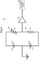
- the electric circuit 100 includes a first power source 101, a second power source 102, a first resistor 103, a second resistor 104, an amplifier 105, and a storage device 106.
- the second power source 102, the first power source 101, the first resistor 103, and the second resistor 104 are connected in series in this order.
- the electric circuit 100 is grounded between the first power source 101 and the second power source 102.
- the amplifier 105 inputs the electric potential between the first resistor 103 and the second resistor 104, amplifies the input electric potential, and outputs the amplified electric potential to the storage device 106.
- the storage device 106 stores the signal represented by the electric potential input from the amplifier 105.
- the voltage of the first power source 101 is +V A [V].
- the voltage of the second power source 102 is -V B [V].
- the electric resistance of the first resistor 103 is R s [ ⁇ ].
- the electric resistance of the second resistor 104 is R R [ ⁇ ].
- the piezoresistive element PZ of the sensor 1 constitutes the first resistor 103. Therefore, the first resistor 103 may be regarded as a variable resistor. Also, the second resistor 104 may be regarded as a reference resistor. With such a configuration, the storage device 106 stores a signal depending on the difference between the electric resistance of the first resistor 103 and the electric resistance of the second resistor 104.
- the sensing material has fluidity.
- the sensing material in order to form the volume change body 14 by filling the storage space with the sensing material, the sensing material preferably has a low viscosity, good wettability with a wall forming the storage space, ease of inflow into the storage space, and ease of solidification without flowing out from the storage space.
- the sensing material preferably has a viscosity measured by a Brookfield type (in other words, B-type) viscosity meter of 1000 [mPa ⁇ sec] or less, more preferably 500 [mPa ⁇ sec] or less, furthermore preferably 250 [mPa ⁇ sec] or less, particularly preferably 200 [mPa ⁇ sec] or less, and most preferably 100 [mPa ⁇ sec] or less.
- B-type Brookfield type
- the optimum viscosity of the sensing material may vary depending on the material constituting the third layered body 13, the state of the wall surface forming the storage space, the shape of the storage space, and the size of the storage space.
- the viscosity of the sensing material is less than 1 [mPa ⁇ sec]
- the concentration of solute contained in the sensing material tends to be excessively low, so that the solute is likely to be unevenly distributed in the storage space. Therefore, the viscosity of the sensing material is preferably 1 [mPa ⁇ sec] or more.
- the viscosity of the sensing material is larger than 1000 [mPa ⁇ sec], the fluidity of the sensing material tends to be excessively low, which makes it difficult to fill the storage space with the sensing material. Therefore, the viscosity of the sensing material is preferably 1000 [mPa ⁇ sec] or less.
- the sensing material has a value of 1 [mPa ⁇ sec] to 1000 [mPa ⁇ sec] as the viscosity measured by the B-type viscosity meter.
- the solvent contained in the sensing material has a sufficiently low surface tension.
- the solvent may be represented as a flux.
- the optimum surface tension of the solvent may vary depending on the filling method of the sensing material described below.
- the method of filling the storage space with the sensing material a technique called dipping method (in other words, dip coating method or the like), spray coating method, or spin coating method may be used.
- the sensing material may be filled into the storage space using an inkjet printer or a needle dispenser.
- the dipping method is suitable for increasing the efficiency of the operation of filling the storage space with the sensing material.
- the solvent contained in the sensing material may be able to dissolve at least a part of the solute contained in the sensing material.
- the solvent dissolves at least a part of the solute contained in the sensing material to constitute a solution or a suspension (for example, colloid solution or slurry liquid).
- the solvent may be water, alcoholic solvent (for example, isopropyl alcohol, ethanol, or phenoxyethanol), formamide-based solvent (for example, N, N-dimethylformamide), ketone-based solvent (for example, acetone, cyclohexanone, or 2-butanone), ether-based solvent (for example, diethyl ether), halogen-based solvent (for example, dichloroform or chloroform), polar solvent with cyclic compounds (for example, 2-pyrrolidone, N-methyl-2-pyrrolidone, or tetrahydrofuran), or benzene-based solvent (for example, toluene or xylene).
- alcoholic solvent for example, isopropyl alcohol, ethanol, or phenoxyethanol
- formamide-based solvent for example, N, N-dimethylformamide
- ketone-based solvent for example, acetone, cyclohexanone, or 2-butanone
- ether-based solvent for example,
- the sensing material is synthetic polymer (for example, thermoplastic polymer, thermosetting polymer, or photocurable polymer), polymer originating from natural matter (for example, biomolecule), inorganic material (for example, metal or ceramics), carbon material, or composition including at least one of the foregoing.
- the sensing material may include fine particles of inorganic material, carbon material, low molecular compound, or polymer.
- Non Patent Literature 1 " Practical Plastics Encyclopedia”, edited by Practical Plastics Encyclopedia Editorial Committee, Industrial Research Committee, 1993
- the sensing material may include one type of thermoplastic polymer or may include two or more types of thermoplastic polymers.
- the thermoplastic polymer may be polyolefin resin (for example, polyethylene, polypropylene, polystyrene, polyvinyl chloride, or polyvinyl alcohol), a polyolefin-based wax (for example, polyethylene oligomer or polypropylene oligomer), thermoplastic acrylic resin, polycarbonate resin, thermoplastic polyester resin, polyamide resin, polyimide resin, acrylonitrile butadiene styrene (ABS) resin, elastomer (for example, polyolefin-based elastomer, hydrogenated styrene-based block copolymer, or hydrogenated styrene-based random copolymer), super engineering plastic (for example, polyphenylene sulfide, polyamide imide, polyether sulfone, or polyether ether ketone), or syndiotactic polystyrene.
- polyolefin resin for example, polyethylene, polypropylene, polystyren
- thermosetting polymer or the photocurable polymer is acrylic resin, unsaturated polyester resin, epoxy resin, phenol resin, urea resin, polyurethane resin, melamine resin, silicone resin, alkyd resin, or thermosetting polyimide.
- monomer before curing and initiator may be mixed, immediately after that, the mixture may be filled in the storage space, and the mixture may be cured by heat or light to form the volume change body 14.
- the polymer originating from natural matter is polysaccharide originating from natural matter (for example, cellulose, chitin, chitosan, hyaluronic acid, or xanthan gum), polysaccharide derivative originating from natural matter, amino acid polymer, amino acid polymer derivative, protein (for example, gelatin or collagen), or protein derivative.
- natural matter for example, cellulose, chitin, chitosan, hyaluronic acid, or xanthan gum
- polysaccharide derivative originating from natural matter for example, amino acid polymer, amino acid polymer derivative, protein (for example, gelatin or collagen), or protein derivative.
- the inorganic material is made of at least one of materials selected from the group of glass fiber, carbon fiber, and inorganic filler.
- the inorganic filler is amorphous filler (for example, calcium carbonate, silica, kaolin, clay, titanium oxide, barium sulfate, zinc oxide, hydroxide aluminum, alumina, or magnesium hydroxide), a plate-like filler (for example, talc, mica, or glass flake), needle-like filler (for example, wollastonite, potassium titanate, basic magnesium sulfate, sepiolite, xonotlite, or aluminum borate), conductive filler (for example, metal powder, metal flake, carbon black, or carbon nanotube), glass bead, glass powder, apatite, or zeolite.
- amorphous filler for example, calcium carbonate, silica, kaolin, clay, titanium oxide, barium sulfate, zinc oxide, hydroxide aluminum, alumina, or magnesium hydroxide
- a plate-like filler for example, talc, mica, or glass flake
- needle-like filler for example,
- the sensing material may include one type of inorganic filler or may include two or more types of inorganic fillers.
- the surface of the inorganic filler may be coated with carbon or may be subjected to silane coupling treatment or the like.
- the carbon material is made of at least one of materials selected from the group of activated carbon, carbon nanotube, and graphite.
- the sensing material may include synthesized porous body such as metal organic framework (MOF).
- MOF metal organic framework
- the metal organic framework may be referred to as porous coordination polymer.
- the metal organic framework may be Basolite (registered trademark) C300 (manufactured by BASF) or the like.
- the sensing material may include an additive.
- the additive may be a flame retardant (for example, brominated bisphenol, brominated epoxy resin, brominated polystyrene, brominated polycarbonate, triphenyl phosphate, phosphonamide, or red phosphorus), a flame retardant aid (for example, antimony trioxide or sodium antimonate), a heat stabilizer (for example, phosphate ester, or phosphite ester), an antioxidant (for example, hindered phenol), a heat-resistant agent, a weathering agent, a light stabilizer, a mold release agent, a flow modifier, a colorant, a pigment, a lubricant, an antistatic agent, a crystal nucleating agent, a plasticizer, a foaming agent, a halogen catcher, or an anti-drip agent.
- a flame retardant for example, brominated bisphenol, brominated epoxy resin, brominated polystyrene, brominated polycarbonate
- the sensing material may include spherical particles.
- the sensing material including spherical particles has a higher fluidity than the sensing material including non-spherical particles so that the storage space can easily be filled with the sensing material.
- the sensing material when the target is a carbonic acid gas, the sensing material may include potassium hydroxide.
- the sensing material when the target is temperature, the sensing material may include polyethylene.
- the sensing material when the target is humidity, the sensing material may include nylon.
- the sensing material when the target is electromagnetic wave, the sensing material may include black carbon.
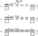
- the senor 1 is manufactured according to the process illustrated in Figs. 9 and 10 . Note that at least a part of the sensor 1 may be manufactured according to a process different from the process illustrated in Figs. 9 and 10 .
- a silicon on insulator (SOI) substrate is prepared.
- the SOI substrate consists of a first silicon layer LA, an insulating layer LB in contact with the first silicon layer LA, a second silicon layer LC in contact with the insulating layer LB.
- the insulating layer LB is made of silicon dioxide.
- boron is added to the second silicon layer LC.
- a technique called doping is used for the addition of boron.
- the contact resistance of the conductor can be reduced.
- a thin film made of aluminum is formed on the surface of the second silicon layer LCA opposite to the insulating layer LB.
- a technique called sputtering is used to form the thin film made of aluminum.
- the first wiring 1333 and the second wiring 1334 are formed by removing a part of the formed thin film.
- a technique called metal etching is used to remove the part of the thin film.
- the second silicon layer LCA corresponds to the first member and the second member.
- the third layered body 13 is formed by removing a part of the second silicon layer LCA.
- a technique called dry etching is used to remove the part of the second silicon layer LCA.
- the first layered body 11 and the second layered body 12 are formed by removing a part of the first silicon layer LA and a part of the insulating layer LB, respectively.
- a technique called deep reactive ion etching (deep RIE) and vapor hydrogen fluoride etching (Vapor HF Etching) is used to remove the part of the first silicon layer LA and the part of the insulating layer LB.
- an insulator thin film OL is formed on the exposed surface of the third layered body 13, the first wiring 1333, and the second wiring 1334.
- the insulator thin film OL is made of aluminum oxide.
- a technique called atomic layer deposition is used to form the insulator thin film.
- the insulator thin film has a thickness of 5 nm to 50 nm. In this example, the thickness of the insulator thin film is 20nm.
- terminals for connection are formed by removing a part of the insulator thin film OL formed on the surface of the first wiring 1333 and a part of the insulator thin film OL formed on the surface of the second wiring 1334.
- a technique called ion milling is used to form the terminals for connection.
- the volume change body 14 is formed by filling the storage space of the body member 132 with the sensing material.
- a technique called dipping method is used to form the volume change body 14.
- the sensing material is filled in the storage space of the body member 132 by immersing the body member 132 in a solution which is the sensing material.
- the volume change body 14 is formed by drying the filled sensing material at a temperature of 10 to 350°C.
- the sensor 1 is manufactured.
- the volume change body 14 receives the target, so that the volume increases depending on the amount of the target.
- the volume change body 14 causes the stress including the component in the negative direction of the y-axis at the second end 1322 of the body member 132.
- the stress occurred at the second end 1322 of the body member 132 is transmitted to the detection member 133.
- the electric resistance of the piezoresistive element PZ of the detection member 133 changes depending on the stress transmitted from the body member 132.
- the electric circuit 100 stores the signal in the storage device 106 depending on the difference between the electric resistance (in this example, the electric resistance of the first resistor 103) of the piezoresistive element PZ of the detection member 133 and the electric resistance of the second resistor 104.
- the sensor 1 detects the target.
- the body member 132 has a flat plate-like shape, the first end 1321 in the first direction (the y-axis direction in this example) being supported, and the storage space opening at at least one of both end faces in the thickness direction of the body member 132.
- the volume change body 14 whose volume changes depending on the amount of the target, is supported by the body member 132 so that at least a part of the volume change body 14 is stored in the storage space.
- the detection member 133 is in contact with the second end 1322 in the first direction of the body member 132, and detects the stress caused by the change in the volume of the volume change body 14.
- the volume change body 14 is stored in the storage space, even if the volume of the volume change body 14 changes, the occurrence of stress in the thickness direction of the body member 132 can be suppressed. This can prevent the body member 132 from bending. Therefore, the occurrence of stress in the thickness direction of the body member 132 at the second end 1322 can be suppressed. As a result, the change in the volume of the volume change body 14 can be reflected with high accuracy in the stress, which occurs at the second end 1322, in the direction along the body member 132. In other words, the sensor 1 can detect the target with high accuracy.
- the storage space opens at both of the end faces in the thickness direction of the body member 132.
- the volume of the volume change body 14 changes, the stress occurring in the thickness direction of the body member 132 can be suppressed as compared with the case where the storage space opens only at one end in the thickness direction of the body member. Therefore, the change in the volume of the volume change body 14 can be reflected with high accuracy in the stress occurred at the second end 1322. As a result, the target can be detected with high accuracy.
- the storage space includes a slit-like hole extending in the second direction (the x-axis direction in this example) orthogonal to the first direction (the y-axis direction in this example).
- the volume change body 14 can be easily stored in the storage space.
- the component in the first direction in the stress caused by the change in the volume of the volume change body 14 in the body member 132 can be increased. Therefore, the change in the volume of the volume change body 14 can be reflected with high accuracy in the stress occurred at the second end 1322. As a result, the target can be detected with high accuracy.
- the storage space includes a plurality of the holes, and the plurality of holes are arranged along the first direction (the y-axis direction in this example).
- the amount of the volume change body 14 can be easily increased by increasing the number of the holes.
- the plurality of holes are arranged along the first direction, the component in the first direction in the stress caused by the change in the volume of the volume change body 14 in the body member 132 can be increased. Therefore, the change in the volume of the volume change body 14 can be reflected with high accuracy in the stress occurring at the second end 1322. As a result, the target can be detected with high accuracy.
- the detection member 133 includes the first supported member 1331.
- the first supported member 1331 whose tip is supported, extends from the second end 1322 to the first direction (the y-axis direction in this example).
- the detection member 133 detects the stress caused by the change in the volume of the volume change body 14 at the first supported member 1331.
- the compressive stress or the tensile stress caused by the change in the volume of the volume change body 14 in the first supported member 1331 can be increased. Therefore, the change in the volume of the volume change body 14 can be reflected with high accuracy in the stress occurring in the first supported member 1331. As a result, the target can be detected with high accuracy.
- the first supported member 1331 has a narrower width than a length of the body member 132 in the second direction (the x-axis direction in this example) orthogonal to the first direction (the y-axis direction in this example).
- the stress caused by the change in the volume of the volume change body 14 in the first supported member 1331 can be larger than the stress occurring in the body member 132. Therefore, the change in the volume of the volume change body 14 can be reflected with high accuracy in the stress occurring in the first supported member 1331. As a result, the target can be detected with high accuracy.
- the detection member 133 includes the second supported member 1332.
- the second supported member 1332 whose tip is supported, extends from the second end 1322 in the first direction (the y-axis direction in this example).
- the detection member 133 has the piezoresistive element PZ located in the first supported member 1331.
- the detection member 133 includes the first wiring 1333 that connects the piezoresistive element PZ and the tip of the first supported member 1331, and the second wiring 1334 that connects the piezoresistive element PZ and the tip of the second supported member 1332 through the body member 132.
- the leak current occurring between the first wiring 1333 and the second wiring 1334 can be suppressed. Therefore, the target can be detected with high accuracy.
- the central portion in the extension direction, in which the first supported member 1331 extends, of the first supported member 1331 has a narrower width than a width of each of the end portions in the extension direction of the first supported member 1331.
- the detection member 133 detects the stress caused by the change in the volume of the volume change body 14 in the central portion in the extension direction of the first supported member 1331.
- the stress caused by the change in the volume of the volume change body 14 in the central portion in the extension direction of the first supported member 1331 can be larger than the stress occurring in each end portion in the extension direction of the first supported member 1331. Therefore, the change in the volume of the volume change body 14 can be reflected with high accuracy in the stress occurring in the central portion. As a result, the target can be detected with high accuracy.
- the volume change body 14 is made of material whose elastic modulus is lower than that of the body member 132.
- the stress distribution, which is caused by the change in the volume of the volume change body 14, in the volume change body 14 can be close to a uniform state.
- the change in the volume of the volume change body 14 can be reflected with high accuracy in the stress occurred in the body member 132.
- the target can be detected with high accuracy.
- the volume change body 14 may be made of material having an elastic modulus higher than that of the body member 132.
- the deformation of the body member 132 caused by the change in the volume of the volume change body 14 can be increased.
- the change in the volume of the volume change body 14 can be reflected with high accuracy in the stress, which occurs at the second end 1322, in the direction along the body member 132.
- the sensor 1 can detect the target with high accuracy.
- the volume change body 14 has the change in the elastic modulus before and after the change in the volume of the volume change body 14 larger than that of the body member 132.
- the strength of the sensor 1 before the change in the volume of the volume change body 14 can be increased.
- the stress distribution, which is caused by the change in the volume of the volume change body 14, in the volume change body 14 can be close to a uniform state.
- the change in the volume of the volume change body 14 can be reflected with high accuracy in the stress occurring in the body member 132.
- the target can be detected with high accuracy.
- the method of manufacturing the sensor 1 of the first embodiment includes filling the storage space with the sensing material having fluidity and drying the filled sensing material to form the volume change body 14.
- the volume change body 14 filling the storage space can be easily formed.
- the viscosity of the sensing material is a value of 1 [mPa ⁇ sec] to 1000 [mPa ⁇ sec] .
- the fluidity of the sensing material is sufficiently high so that the sensing material can easily fill the storage space.
- the volume change body 14 is entirely stored in the storage space of the body member 132.
- a part of the volume change body 14 may be stored in the storage space, and the other part of the volume change body 14 may cover at least a part of both end faces in the thickness direction of the body member 132.
- the volume change body 14 may cover an area in which the space formation portion 1323 exists in both end faces in the thickness direction of the body member 132.
- the body member 132 is in contact with the frame 131 at the second end 1322 through two supported members consisting of the first supported member 1331 and the second supported member 1332.
- the body member 132 may be in contact with the frame 131 at the second end 1322 through one supported member, or through three or more supported members.
- the body member 132 may be in contact with the frame 131 at the first end 1321 through one or more supported members.
- each hole included in the storage space formed by the space formation portion 1323 of the body member 132 is a through hole that penetrates the body member 132 in the thickness direction of the body member 132.
- each hole included in the storage space formed by the space formation portion 1323A of the body member 132 may be a bottomed hole that opens at the end face in the positive direction of the z-axis of the body member 132.
- each hole included in the storage space formed by the space formation portion 1323B of the body member 132 may be a first hole that is bottomed and opens at the end face in the positive direction of the z-axis of the body member 132, or a second hole that is bottomed and opens at the end face in the negative direction of the z-axis of the body member 132.
- the holes included in the storage space may be in such a manner that the first hole and the second hole are alternately arranged along the y-axis direction.
- the number of holes included in the storage space formed by the space formation portion 1323 of the body member 132 is 2 or more.
- the number of holes included in the storage space formed by the space formation portion 1323C of the body member 132 may be one.
- the space formation portion 1323C of the body member 132 may have a comb teeth-like shape in the plan view of the body member 132 (in other words, when the body member 132 is viewed in the negative direction of the z-axis).
- the storage space formed by the space formation portion 1323 of the body member 132 includes the slit-like holes.
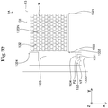
- the space formation portion 1323C of the body member 132 may have a mesh-like shape in the plan view of the body member 132 (in other words, when the body member 132 is viewed in the negative direction of the z-axis).
- each hole included in the storage space may be a regular hexagon in the plan view of the body member 132.
- Each hole included in the storage space may have a shape (circular, elliptical, or polygonal shape other than regular hexagon) other than regular hexagon in the plan view of the body member 132.
- the corner portion of the storage space formed by the space formation portion 1323 of the body member 132 may have a curved shape or a chamfered shape.
- the sensing material may unlikely spread over the corner portion.
- the volume change body 14 may not fill the storage space.
- the change in the volume of the volume change body 14 may not be reflected with high accuracy in the stress, which occurs at the second end 1322, in the direction along the body member 132.
- the corner portion of the storage space has a curved shape or a chamfered shape and the volume change body 14 is formed by filling the storage space with the sensing material having fluidity, the sensing material can spread over the corner portion. Therefore, the volume change body 14 can fill the storage space. As a result, the change in the volume of the volume change body 14 can be reflected with high accuracy in the stress, which occurs at the second end 1322, in the direction along the body member 132. In other words, the target can be detected with high accuracy.
- the sensor 1 of the first embodiment may be applied to a detecting device that detects each of different targets.
- the detecting device preferably includes a plurality of the sensors 1 having different sensing materials.
- the plurality of sensors 1 may be arranged in a grid pattern.
- the sensing material is a solution obtained by dissolving OLESTER (registered trademark) Q517 (manufactured by Mitsui Chemicals, Inc.) as a solute in a mixed solvent consisting of cyclohexanone and dimethylformamide.
- the mixed solvent has a mixture ratio of cyclohexanone to dimethylformamide of 2:1.
- the weight ratio of the solute to the mixed solvent in the sensing material is 1:7.
- the sensing material has a viscosity of 2 [mPa ⁇ sec].
- a B-type rotating viscosity meter (TV-35 type viscosity meter, manufactured by Toki Sangyo Co., Ltd.)
- 1 mL of solution is placed in a measurement container and the viscosity is measured at 25°C and 50% relative humidity (RH) after rotating for 60 seconds at a rotation speed of 50 rpm.
- RV relative humidity
- the sensing material is filled in the storage space of the body member 132 by dipping the body member 132 into the solution which is the sensing material.
- the filled sensing material is dried at a room temperature for 8 to 12 hours to form the volume change body 14.
- the volume change body 14 has an elastic modulus (in this example, Young's modulus) of 2.5 GPa.
- Young's modulus In this example, Young's modulus
- the elastic modulus is measured under the condition where the test force is 0.5 mN, the load speed is 0.142 mN/sec, and the holding time is 5 sec. Note that the elastic modulus described later is also measured similarly to this example.
- the ratio ⁇ R/R s of the variation ⁇ R of the electric resistance R s of the first resistor 103 to the electric resistance R s of the first resistor 103 is represented by Math. 1.
- V OUT represents the electric potential (in other words, the electric potential representing the signal stored in the storage device 106) output from the amplifier 105.
- G represents the amplification rate (in other words, the ratio of the electric potential output from the amplifier 105 to the electric potential input to the amplifier 105) of the amplifier 105.
- I represents the current flowing through the electric circuit illustrated in Fig. 8 as represented in Math. 2 .
- the electric potential V OUT representing the signal stored in the storage device 106 changes in proportion to the ratio AR/R S of the variation ⁇ R of the electric resistance R s of the first resistor 103 to the electric resistance R s of the first resistor 103.
- the senor 1 detects humidity as the target. In a second operation example, the sensor 1 detects hydrogen sulfide (H 2 S) as the target.
- H 2 S hydrogen sulfide
- the senor 1 is installed inside a gas chamber. Further, in both of the first operation example and the second operation example, a humidity sensor for measuring a reference value of humidity is installed inside the gas chamber.
- a gas consisting of nitrogen (in other words, nitrogen gas) is supplied into the gas chamber for a certain period, and then a gas consisting of water and nitrogen (in other words, a water mixed gas) is supplied into the gas chamber for a certain period.
- nitrogen gas in other words, nitrogen gas
- water and nitrogen in other words, a water mixed gas
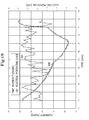
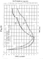
- the signal S11 stored in the storage device 106 in the sensor 1 changes so as to follow the reference signal S10 represented by the reference value measured by the humidity sensor with sufficiently high accuracy.
- the signal S21 stored in the storage device 106 in the sensor 1 changes so as to follow the reference signal S20 represented by the reference value measured by the humidity sensor with sufficiently high accuracy even with repeated changes in the humidity.
- the electric potential represented by the signal stored in the storage device 106 in the sensor 1 and the reference value measured by the humidity sensor have a strong correlation (in this example, a linear relationship).
- the humidity can be detected with high accuracy over a relatively wide range of humidity.
- the nitrogen gas is supplied into the gas chamber for a certain period, and then, a gas consisting of nitrogen and hydrogen sulfide and having a hydrogen sulfide concentration of 4.75 ppm (in other words, hydrogen sulfide mixed gas) is supplied into the gas chamber for a certain period.
- a gas consisting of nitrogen and hydrogen sulfide and having a hydrogen sulfide concentration of 4.75 ppm (in other words, hydrogen sulfide mixed gas) is supplied into the gas chamber for a certain period.
- the concentration of hydrogen sulfide inside the gas chamber changes over time.
- the concentration of hydrogen sulfide (H 2 S) is measured by a gas detector tube (hydrogen sulfide No. 4LB, manufactured by Gastec Corporation).
- the reference signal S30 represented by the reference value measured by the humidity sensor represents the reference value decreasing with the passage of time.
- the signal S31 stored in the storage device 106 of the sensor 1 represents the electric potential increasing with the passage of time.
- the volume change body 14 of the sensor 1 is estimated to interact with molecules (in this example, hydrogen sulfide) other than humidity (for example, adsorb or sorb hydrogen sulfide).
- molecules in this example, hydrogen sulfide
- humidity for example, adsorb or sorb hydrogen sulfide
- the volume of the volume change body 14 changes due to the interaction of the volume change body 14 with the target. Therefore, the amount of the target can be reflected with high accuracy in the change in the volume of the volume change body 14. As a result, the target can be detected with high accuracy.
- the sensing material is a solution obtained by dissolving U-VAN (registered trademark) 20SE60 (manufactured by Mitsui Chemicals, Inc.) as a solute in a solvent consisting of dimethylformamide.
- the weight ratio of the solute to the mixed solvent in the sensing material is 1:3.
- the volume change body 14 is formed using the dipping method.
- the sensor 1 detects humidity as the target.
- the sensor 1 detects hydrogen sulfide (H 2 S) as the target.
- the nitrogen gas is supplied into the gas chamber for a certain period, and then the water-mixed gas is supplied into the gas chamber for a certain period.
- the humidity inside the gas chamber changes over time.
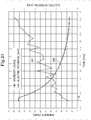
- the signal S41 stored in the storage device 106 in the sensor 1 does not change to follow the reference signal S40 represented by the reference value measured by the humidity sensor.
- the responsiveness of the sensor 1 of the second example to humidity is lower than that of the sensor 1 of the first example.
- the hydrogen sulfide mixed gas is supplied into the gas chamber for a certain period.
- the concentration of hydrogen sulfide inside the gas chamber changes over time.
- the reference signals S50, S60 represented by the reference values measured by the humidity sensor represent the reference values decreasing with the passage of time.
- the signals S51 and S61 stored in the storage device 106 of the sensor 1 represent the electric potentials increasing with the passage of time.
- the volume change body 14 of the sensor 1 is estimated to interact with molecules (in this example, hydrogen sulfide) other than humidity (for example, adsorb or sorb hydrogen sulfide).
- molecules in this example, hydrogen sulfide
- humidity for example, adsorb or sorb hydrogen sulfide
- the volume of the volume change body 14 changes due to the interaction of the volume change body 14 with the target. Therefore, the amount of the target can be reflected with high accuracy in the change in the volume of the volume change body 14. As a result, the target can be detected with high accuracy.
- the sensing material is a solution obtained by dissolving EPOKEY (registered trademark) 863 (manufactured by Mitsui Chemicals, Inc.) as a solute in a solvent consisting of dimethylformamide.
- EPOKEY registered trademark
- the weight ratio of the solute to the mixed solvent in the sensing material is 1:7.
- the volume change body 14 is formed using the dipping method.
- the elastic modulus (Young's modulus in this example) of the volume change body 14 is 2.5 GPa.
- the sensor 1 detects humidity as the target.
- the sensor 1 detects hydrogen sulfide (H 2 S) as the target.
- the nitrogen gas is supplied into the gas chamber for a certain period, and then the water-mixed gas is supplied into the gas chamber for a certain period.
- the humidity inside the gas chamber changes over time.
- the signal S71 stored in the storage device 106 in the sensor 1 changes to follow the reference signal S70 represented by the reference value measured by the humidity sensor with sufficiently high accuracy.
- the responsiveness of the sensor 1 of the third example to humidity is lower than that of the sensor 1 of the first example.
- the nitrogen gas is supplied into the gas chamber for a certain period, and then the hydrogen sulfide mixed gas is supplied into the gas chamber for a certain period.
- the concentration of hydrogen sulfide inside the gas chamber changes over time.
- the signal S81 stored in the storage device 106 of the sensor 1 decreases, similarly to the reference signal S80 represented by the reference value measured by the humidity sensor, almost monotonically with the passage of time.
- the volume change body 14 of the sensor 1 is estimated to be unlikely to interact with molecules (in this example, hydrogen sulfide) other than humidity (for example, adsorb or sorb hydrogen sulfide).
- molecules in this example, hydrogen sulfide
- humidity for example, adsorb or sorb hydrogen sulfide
- the responsiveness of the sensor 1 in each example is represented in Table 1.
- Table 1 double circles indicate higher responsiveness than circles, and circles indicate higher responsiveness than triangles.
- Table 1 RESPONSIVENESS TO HUMIDITY RESPONSIVENESS TO HYDROGEN SULFIDE FIRST EXAMPLE ⁇ ⁇ SECOND EXAMPLE ⁇ ⁇ THIRD EXAMPLE ⁇ ⁇
- the sensor of the second embodiment differs from the sensor of the first embodiment in that the target is detected based on bending stress. The difference will be mainly described below.
- the one with the same reference sign as used in the first embodiment is the same or substantially the same one.
- the sensor 1A of the second embodiment includes a first layered body 11, a second layered body 12, a third layered body 13, and a volume change body 14.
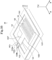
- Fig. 24 is a right front upper perspective view of the sensor 1A.
- Fig. 25 is a right front upper perspective view of the sensor 1A in a state where the sensor 1A is disassembled.
- Fig. 26 is a plan view of the sensor 1A.
- Fig. 27 is a view of the cross section of the sensor 1A cut by a plane represented by an XVIII-XVIII line in Fig. 26 as viewed in the negative direction of the x-axis.
- the third layered body 13 includes a frame 131, a body member 132, and a detection member 133.
- the detection member 133 includes an extension member 1335 in addition to the first supported member 1331, the second supported member 1332, the first wiring 1333, and the second wiring 1334 included in the detection member 133 of the first embodiment.
- the frame 131 has a configuration similar to the frame 131 of the first embodiment.
- the body member 132 has a rectangular-like shape having long sides extending in the y-axis direction and short sides extending in the x-axis direction.
- the body member 132 may have a square-like shape.
- the length of the body member 132 in the y-axis direction is shorter than the length of the hole of the frame 131 in the y-axis direction. In this example, the length of the body member 132 in the y-axis direction is 260 ⁇ m.
- the length of the body member 132 in the x-axis direction is shorter than the length of the hole of the frame 131 in the x-axis direction. In this example, the length of the body member 132 in the x-axis direction is 240 ⁇ m.
- the end in the positive direction of the x-axis of the body member 132 is separated from the frame 131.
- the body member 132 is in contact with the frame 131 at the first end 1321 in the positive direction of the y-axis of the body member 132.
- the first end 1321 in the positive direction of the y-axis of the body member 132 is supported by the frame 131.
- a part of the body member 132 other than the end portion in the negative direction of the x-axis in the second end 1322 in the negative direction of the y-axis is in contact with the extension member 1335.
- the end portion in the negative direction of the x-axis in the second end 1322 in the negative direction of the y-axis of the body member 132 is separated from the frame 131.
- the body member 132 is in contact with the frame 131 at the third end 1324 in the negative direction of the x-axis of the body member 132.
- the third end 1324 in the negative direction of the x-axis of the body member 132 is supported by the frame 131.
- the body member 132 has a space formation portion 1323.
- the space formation portion 1323 forms the storage space opening at both end faces in the z-axis direction (in other words, the thickness direction of the body member 132) of the body member 132.
- the storage space is a through hole that penetrates the body member 132 in the z-axis direction.
- the storage space includes slit portions, each of which has a slit-like shape extending in the x-axis direction, and a connection portion that connects two adjacent slit portions at the central portion in the x-axis direction.
- the slit portions included in the storage space are arranged at equal intervals along the y-axis direction.
- the length in the y-axis direction of each slit portion included in the storage space is a length of 1 ⁇ m to 10 ⁇ m.
- the length in the y-axis direction of each slit portion included in the storage space is 5 ⁇ m.
- the interval in the y-axis direction between the slit portions included in the storage space is a length of 1 ⁇ m to 10 ⁇ m.
- the interval in the y-axis direction between the slit portions included in the storage space is 1 ⁇ m.
- the number of the slit portions included in the storage space is 40. Note that in Figs. 24 to 27 , the slit portions included in the storage space are illustrated in an enlarged manner in the y-axis direction. Therefore, in Figs. 24 to 27 , the slit portions included in the storage space are illustrated in a reduced number manner.
- the length in the x-axis direction of the slit portions included in the storage space is 220 ⁇ m.
- the extension member 1335 has a rectangular-like shape having long sides extending in the x-axis direction and short sides extending in the y-axis direction.
- the end in the negative direction of the x-axis of the extension member 1335 is separated from the frame 131.
- the end in the negative direction of the y-axis of the extension member 1335 is separated from the frame 131.
- a part of the extension member 1335 other than the end portion in the positive direction of the x-axis in the end in the positive direction of the y-axis is in contact with the second end 1322 of the body member 132.
- the end portion in the positive direction of the x-axis in the end in the positive direction of the y-axis of the extension member 1335 is separated from the frame 131.
- the extension member 1335 extends from the second end 1322 to a position (in this example, the position in the positive direction of the x-axis relative to the position in contact with the second end 1322) different from a position in contact with the second end 1322 in the x-axis direction.
- Both end portions in the y-axis direction in the end (in other words, the tip of the extension member 1335) in the positive direction of the x-axis of the extension member 1335 are in contact with the frame 131 through the first supported member 1331 and the second supported member 1332.
- the central portion in the y-axis direction of the tip of the extension member 1335 is separated from the frame 131.
- the first supported member 1331 has a strip-like shape extending in the x-axis direction.
- the end in the positive direction of the x-axis of the first supported member 1331 is in contact with the frame 131.
- the end in the negative direction of the x-axis of the first supported member 1331 is in contact with the end portion in the negative direction of the y-axis in the tip of the extension member 1335.
- the first supported member 1331 extends from the tip of the extension member 1335 to the positive direction of the x-axis.
- the tip of the first supported member 1331 is supported by the frame 131.
- the width (in other words, the length of the first supported member 1331 in the y-axis direction) of the first supported member 1331 is narrower than the width (in other words, the length of the extension member 1335 in the y-axis direction) of the extension member 1335.
- the first supported member 1331 has a notch portion NT.
- a position of the end in the negative direction of the y-axis of the notch portion NT changes toward the positive direction of the y-axis. Therefore, the width of the central portion in an extension direction (the x-axis direction in this example), in which the first supported member 1331 extends, of the first supported member 1331 is narrower than the width of each of the end portions in the extension direction of the first supported member 1331.
- the first supported member 1331 includes a piezoresistive element PZ located in the central portion in the extension direction of the first supported member 1331.
- the piezoresistive element PZ is an element whose electric resistance changes depending on the stress applied to the piezoresistive element PZ.
- the piezoresistive element PZ is an element having a piezoresistive effect.
- the piezoresistive element PZ is embedded in the first supported member 1331 so as to be exposed at the end face in the positive direction of the z-axis of the first supported member 1331.
- the detection member 133 detects the stress transmitted from the body member 132 in the central portion in the extension direction of the first supported member 1331.
- the second supported member 1332 has a strip-like shape extending in the x-axis direction.
- the end in the positive direction of the x-axis of the second supported member 1332 is in contact with the frame 131.
- the end in the negative direction of the x-axis of the second supported member 1332 is in contact with the end portion in the positive direction of the y-axis of the tip of the extension member 1335.
- the second supported member 1332 extends from the tip of the extension member 1335 to the positive direction of the x-axis.
- the tip of the second supported member 1332 is supported by the frame 131.
- the width (in other words, the length in the y-axis direction of the second supported member 1332) of the second supported member 1332 is narrower than the width of the extension member 1335.
- the width of the central portion in an extension direction (the x-axis direction in this example), in which the second supported member 1332 extends, of the second supported member 1332, is equal to the width of each of the end portions in the extension direction of the second supported member 1332.
- the first wiring 1333 and the second wiring 1334 have similar configurations to the first wiring 1333 and the second wiring 1334 of the first embodiment, respectively, except that the positions are different.
- one end portion of the first wiring 1333 is in contact with the end portion in the positive direction of the x-axis of the piezoresistive element PZ.
- the other end portion of the first wiring 1333 is located at the outer edge of the frame 131.
- the first wiring 1333 extends from the end portion in the positive direction of the x-axis of the piezoresistive element PZ to the outer edge of the frame 131 through the tip (in other words, the end, which is in contact with the frame 131, of the first supported member 1331) of the first supported member 1331.
- the first wiring 1333 connects the piezoresistive element PZ and the tip of the first supported member 1331.
- One end portion of the second wiring 1334 is in contact with the end portion in the negative direction of the x-axis of the piezoresistive element PZ.
- the other end portion of the second wiring 1334 is located at the outer edge of the frame 131.
- the second wiring 1334 extends from the end portion in the negative direction of the x-axis of the piezoresistive element PZ to the outer edge of the frame 131 through the proximal end (in other words, the end, which is in contact with the extension member 1335, of the first supported member 1331) of the first supported member 1331, the end portion in the positive direction of the x-axis of the extension member 1335, and the second supported member 1332.
- the second wiring 1334 connects the piezoresistive element PZ and the tip (in other words, the end, which is in contact with the frame 131, of the second supported member 1332) of the second supported member 1332 through the extension member 1335.
- the volume change body 14 is supported by the body member 132 so as to be stored in the storage space of the body member 132.
- first wiring 1333 and the second wiring 1334 are connected to a similar electric circuit to that of the first embodiment.
- the extension member 1335 extends from the second end 1322 to a position different from the position in contact with the second end 1322 in the second direction (the x-axis direction in this example) orthogonal to the first direction (the y-axis direction in this example).
- the first supported member 1331 extends from the tip of the extension member 1335. The tip of the first supported member 1331 is supported.
- the detection member 133 detects the stress caused by the change in the volume of the volume change body 14 in the first supported member 1331.
- the bending stress caused by the change in the volume of the volume change body 14 in the first supported member 1331 can be increased. Therefore, the change in the volume of the volume change body 14 can be reflected with high accuracy in the stress occurring in the first supported member 1331. As a result, the target can be detected with high accuracy.
- the width of the first supported member 1331 is narrower than the width of the extension member 1335.
- the stress caused by the change in the volume of the volume change body 14 in the first supported member 1331 can be larger than the stress occurring in the extension member 1335. Therefore, the change in the volume of the volume change body 14 can be reflected with high accuracy in the stress occurring in the first supported member 1331. As a result, the target can be detected with high accuracy.
- the detection member 133 includes the second supported member 1332, whose tip is supported, that extends from the tip of the extension member 1335.
- the detection member 133 has the piezoresistive element PZ located in the first supported member 1331.
- the detection member 133 includes the first wiring 1333 connecting the piezoresistive element PZ and the tip of the first supported member 1331, and the second wiring 1334 connecting the piezoresistive element PZ and the tip of the second supported member 1332 through the extension member 1335.
- the leak current occurring between the first wiring 1333 and the second wiring 1334 can be suppressed. Therefore, the target can be detected with high accuracy.
- the width of the central portion in the extension direction, in which the first supported member 1331 extends, of the first supported member 1331 is narrower than the width of each of the end portions in the extension direction of the first supported member 1331.
- the detection member 133 detects the stress caused by the change in the volume of the volume change body 14 in the central portion in the extension direction of the first supported member 1331.
- the stress caused by the change in the volume of the volume change body 14 in the central portion in the extension direction of the first supported member 1331 can be larger than the stress occurring in each of the end portions in the extension direction of the first supported member 1331. Therefore, the change in the volume of the volume change body 14 can be reflected with high accuracy in the stress occurring in the central portion. As a result, the target can be detected with high accuracy.
- the volume change body 14 is entirely stored in the storage space of the body member 132.
- a part of the volume change body 14 may be stored in the storage space, and the other part of the volume change body 14 may cover at least a part of both end faces in the thickness direction of the body member 132.
- the volume change body 14 may cover an area in which the space formation portion 1323 exists in both end faces in the thickness direction of the body member 132.
- the extension member 1335 is in contact with the frame 131 at the tip of the extension member 1335 through two supported members consisting of the first supported member 1331 and the second supported member 1332.
- the extension member 1335 may be in contact with the frame 131 at the tip of the extension member 1335 through one supported member, or through three or more supported members.
- the first supported member 1331 and the second supported member 1332 extend from both end portions in the y-axis direction in the end in the positive direction of the x-axis of the extension member 1335 to the positive direction of the x-axis, respectively.
- the first supported member 1331J and the second supported member 1332J may extend from the end portion in the positive direction of the x-axis in the end in the negative direction of the y-axis of the extension member 1335 to the negative direction of the y-axis, respectively.
- the first supported member 1331K and the second supported member 1332K may extend from the end portion in the positive direction of the x-axis in the end in the positive direction of the y-axis of the extension member 1335 to the positive direction of the y-axis, respectively.
- the detection member 133 may include a connection portion 1336 that connects the first supported member 1331K and the second supported member 1332K to the frame 131.
- the storage space formed by the space formation portion 1323 of the body member 132 is one hole including the slit portions.
- the storage space formed by the space formation portion 1323L of the body member 132 may include multiple slit-like holes extending in the x-axis direction, similarly to the space formation portion 1323 of the first embodiment.
- each hole included in the storage space may be a bottomed hole that opens at the end face in the positive direction of the z-axis of the body member 132.
- each hole included in the storage space may be a first hole that is bottomed and opens at the end face in the positive direction of the z-axis of the body member 132, or a second hole that is bottomed and opens at the end face in the negative direction of the z-axis of the body member 132.
- the storage space formed by the space formation portion 1323 of the body member 132 includes the slit portions and the connection portion that connects the slit portions at the central portion.
- the space formation portion 1323M of the body member 132 may have a comb teeth-like shape in the plan view of the body member 132 (in other words, when the body member 132 is viewed in the negative direction of the z-axis).
- the space formation portion 1323N of the body member 132 may have a mesh-like shape in the plan view of the body member 132 (in other words, when the body member 132 is viewed in the negative direction of the z-axis).
- each hole included in the storage space may be a regular hexagon in the plan view of the body member 132.
- Each hole included in the storage space may have a shape (circular, elliptical, or polygonal shape other than regular hexagon) other than regular hexagon in the plan view of the body member 132.
- the sensor 1A of the second embodiment may be applied to a detecting device that detects each of different targets.
- the detecting device preferably includes a plurality of the sensors 1A having different sensing materials.
- the plurality of sensors 1A may be arranged in a grid pattern.
- the sensor of the third embodiment differs from the sensor of the first embodiment in that the target is detected based on vibration. The difference will be mainly described below.
- the one with the same reference sign as used in the first embodiment is the same or substantially the same one.
- the sensor 1B of the third embodiment includes a first layered body 11, a second layered body 12, a third layered body 13, and a volume change body 14.
- Fig. 33 is a right front upper perspective view of the sensor 1B.
- Fig. 34 is a right front upper perspective view of the sensor 1B in a state where the sensor 1B is disassembled.
- Fig. 35 is a plan view of the sensor 1B.
- Fig. 36 is a view of the cross section of the sensor 1B cut by a plane represented by an XXXVI-XXXVI line of Fig. 35 as viewed in the negative direction of the x-axis.
- the third layered body 13 includes a frame 131, a body member 132, and a detection member 133.
- the frame 131 has a similar configuration to the frame 131 of the first embodiment.
- the body member 132 has a rectangular-like shape having long sides extending in the x-axis direction and short sides extending in the y-axis direction.
- the body member 132 may have a square-like shape.
- the length of the body member 132 in the y-axis direction is shorter than the length of the hole of the frame 131 in the y-axis direction.
- the length of the body member 132 in the y-axis direction is a length of 1/3 to 2/3 of the length of the hole of the frame 131 in the y-axis direction.
- the length of the body member 132 in the y-axis direction is 220 ⁇ m.
- the length of the body member 132 in the x-axis direction is shorter than the length of the hole of the frame 131 in the x-axis direction.
- the length of the body member 132 in the x-axis direction is 300 ⁇ m. Both ends in the x-axis direction of the body member 132 are separated from the frame 131.
- the body member 132 is in contact with the frame 131 at the first end 1321 in the positive direction of the y-axis of the body member 132.
- the first end 1321 in the positive direction of the y-axis of the body member 132 is supported by the frame 131.
- the central portion in the x-axis direction in the second end 1322 in the negative direction of the y-axis of the body member 132 is in contact with the frame 131 through the detection member 133.
- a part of the body member 132 other than the central portion in the x-axis direction in the second end 1322 in the negative direction of the y-axis is separated from the frame 131.
- the body member 132 has a space formation portion 1323 that forms the storage space.
- the storage space opens at both end faces in the z-axis direction (in other words, the thickness direction of the body member 132) of the body member 132.
- the storage space includes slit-like holes extending in the x-axis direction.
- each hole included in the storage space is a through hole that penetrates the body member 132 in the z-axis direction.
- the holes included in the storage space are arranged at equal intervals along the y-axis direction.
- the length in the y-axis direction of each hole included in the storage space is a length of 0.1 ⁇ m to 10 ⁇ m.
- the length in the y-axis direction of each hole included in the storage space is 1 ⁇ m.
- the interval in the y-axis direction between the holes included in the storage space is a length of 0.1 ⁇ m to 10 ⁇ m.
- the interval in the y-axis direction between the holes included in the storage space is 1 ⁇ m.
- the number of the holes included in the storage space is 80. Note that in Figs. 33 to 36 , the holes included in the storage space are illustrated in an enlarged manner in the y-axis direction. Therefore, in Figs. 33 to 36 , the holes included in the storage space are illustrated in a reduced number manner.
- the length of the slit-like holes included in the storage space in the x-axis direction is 280 ⁇ m.
- the detection member 133 includes a supported member 1337, a first wiring 1338a, a second wiring 1338b, and a third wiring 1338c.
- the supported member 1337 has a strip-like shape extending in the y-axis direction.
- the end in the negative direction of the y-axis of the supported member 1337 is in contact with the frame 131.
- the end in the positive direction of the y-axis of the supported member 1337 is in contact with the central portion in the x-axis direction in the second end 1322 of the body member 132.
- the supported member 1337 extends from the second end 1322 of the body member 132 to the negative direction of the y-axis.
- the tip of the supported member 1337 is supported by the frame 131.
- the width (in other words, the length of the supported member 1337 in the x-axis direction) of the supported member 1337 is narrower than the width of the body member 132 (in other words, the length of the body member 132 in the x-axis direction).
- the width of the supported member 1337 is 40 ⁇ m.
- the supported member 1337 includes a pair of piezoresistive elements PZ1, PZ2 which are located in the end portion (in other words, the portion supported by the frame 131) in the negative direction of the y-axis of the supported member 1337.
- each piezoresistive element PZ1, PZ2 extends to the end portion in the positive direction of the y-axis of the frame 131.
- the piezoresistive elements PZ1, PZ2 are separated from each other in the x-axis direction.
- Each piezoresistive element PZ1, PZ2 is an element whose electric resistance changes depending on the stress applied to respective piezoresistive element PZ1, PZ2.
- each piezoresistive element PZ1, PZ2 is an element having a piezoresistive effect.
- each piezoresistive element PZ1, PZ2 is embedded in the supported member 1337 so as to be exposed at the end face in the positive direction of the z-axis of the supported member 1337.
- Each of the first wiring 1338a, the second wiring 1338b, and the third wiring 1338c is made of conductor (aluminum in this example). As illustrated in Figs. 35 and 36 , the first wiring 1338a, the second wiring 1338b, and the third wiring 1338c are laid on the end face in the positive direction of the z-axis of the third layered body 13.
- the thickness (in other words, the length in the z-axis direction of each of the first wiring 1338a, the second wiring 1338b, and the third wiring 1338c) of each of the first wiring 1338a, the second wiring 1338b, and the third wiring 1338c is a thickness of 10 nm to 1 ⁇ m.
- the thickness of each of the first wiring 1338a, the second wiring 1338b, and the third wiring 1338c is 100 nm.
- a part of the exposed surface of the first wiring 1338a, the second wiring 1338b, and the third wiring 1338c is covered with an oxide thin film (not illustrated).
- the other part, which is not covered with the oxide thin film, of the exposed surface of the first wiring 1338a, the second wiring 1338b, and the third wiring 1338c may be used as terminals for connection.
- one end portion of the first wiring 1338a is in contact with the end portion in the negative direction of the y-axis of the piezoresistive element PZ1.
- the other end portion of the first wiring 1338a is located at the outer edge of the frame 131.
- the first wiring 1338a extends from the end portion in the negative direction of the y-axis of the piezoresistive element PZ1 to the outer edge of the frame 131.
- One end portion of the second wiring 1338b is in contact with the end portion in the negative direction of the y-axis of the piezoresistive element PZ2.
- the other end portion of the second wiring 1338b is located at the outer edge of the frame 131.
- the second wiring 1338b extends from the end portion in the negative direction of the y-axis of the piezoresistive element PZ2 to the outer edge of the frame 131.
- One end portion of the third wiring 1338c is in contact with the end portion in the positive direction of the y-axis of the piezoresistive element PZ1.
- the other end portion of the third wiring 1338c is in contact with the end portion in the positive direction of the y-axis of the piezoresistive element PZ2.
- the third wiring 1338c extends from the end portion in the positive direction of the y-axis of the piezoresistive element PZ1 to the end portion in the positive direction of the y-axis of the piezoresistive element PZ2.
- the volume change body 14 is supported by the body member 132 so as to be stored in the storage space of the body member 132.
- first wiring 1338a and the second wiring 1338b are connected to an electric circuit similar to that of the first embodiment.
- the detection member 133 includes the supported member 1337, whose tip is supported, that extends from the second end 1322 to the first direction (in this example, the y-axis direction). Further, the detection member 133 detects the stress caused by the change in the volume of the volume change body 14 at the tip of the supported member 1337.
- the supported member 1337 vibrates in the thickness direction of the supported member 1337 (the z-axis direction in this example) by bending.
- the compressive stress or the tensile stress caused by the change in the volume of the volume change body 14 in the supported member 1337 changes. Therefore, the resonance frequency of the supported member 1337 changes due to the change in the volume of the volume change body 14.
- the change in the volume of the volume change body 14 can be reflected with high accuracy in the frequency of the vibration of the supported member 1337.
- the detection member 133 can detect the change with time in the stress caused by the vibration of the supported member 1337 at the tip (in other words, the portion where the supported member 1337 is supported by the frame 131) of the supported member 1337. Therefore, the detection member 133 can detect the frequency of the vibration of the supported member 1337. As a result, the target can be detected with high accuracy.
- the width of the supported member 1337 is narrower than the length of the body member 132 in the second direction (the x-axis direction in this example) orthogonal to the first direction.
- the stress caused by the change in the volume of the volume change body 14 in the supported member 1337 can be larger than the stress occurring in the body member 132. Therefore, the change in the volume of the volume change body 14 can be reflected with high accuracy in the stress occurring in the supported member 1337. Further, the vibration in the thickness direction of the supported member 1337 can be larger than the vibration in the thickness direction of the body member 132. As a result, the target can be detected with high accuracy.
- the volume change body 14 is entirely stored in the storage space of the body member 132.
- a part of the volume change body 14 may be stored in the storage space, and the other part of the volume change body 14 may cover at least a part of both end faces in the thickness direction of the body member 132.
- the volume change body 14 may cover an area in which the space formation portion 1323 exists in both end faces in the thickness direction of the body member 132.
- the body member 132 is in contact with the frame 131 through the supported member 1337 at the second end 1322.
- the body member 132 may be in contact with the frame 131 at the second end 1322 through multiple supported members.
- the body member 132 may be in contact with the frame 131 at the first end 1321 through one or more supported members.
- each hole included in the storage space formed by the space formation portion 1323 of the body member 132 is a through hole that penetrates the body member 132 in the thickness direction of the body member 132.
- each hole included in the storage space formed by the space formation portion 1323 of the body member 132 may be a bottomed hole that opens at the end face in the positive direction of the z-axis of the body member 132.
- each hole included in the storage space formed by the space formation portion 1323 of the body member 132 may be a first hole that is bottomed and opens at the end face in the positive direction of the z-axis of the body member 132, or a second hole that is bottomed and opens at the end face in the negative direction of the z-axis of the body member 132.
- the holes included in the storage space may be in such a manner that the first hole and the second hole are alternately arranged along the y-axis direction.
- the number of holes included in the storage space formed by the space formation portion 1323 of the body member 132 is 2 or more.
- the number of holes included in the storage space formed by the space formation portion 1323 of the body member 132 may be one.
- the space formation portion 1323 of the body member 132 may have a comb teeth-like shape in the plan view of the body member 132 (in other words, when the body member 132 is viewed in the negative direction of the z-axis).
- the storage space formed by the space formation portion 1323 of the body member 132 includes the slit-like holes.
- the space formation portion 1323 of the body member 132 may have a mesh-like shape in the plan view of the body member 132 (in other words, when the body member 132 is viewed in the negative direction of the z-axis).
- each hole included in the storage space may be a regular hexagon in the plan view of the body member 132.
- Each hole included in the storage space may have a shape (circular, elliptical, or polygonal shape other than regular hexagon) other than regular hexagon in the plan view of the body member 132.
- the sensor 1B of a seventh modified example of the third embodiment may detect the vibration of the supported member 1337 using light instead of stress.
- the sensor 1B may include a laser Doppler vibrometer and may detect the vibration of the supported member 1337 using the laser Doppler vibrometer.
- the senor 1B of an eighth modified example of the third embodiment may include a mechanism or a device for vibrating the supported member 1337.
- the sensor 1B of the third embodiment when the volume of the volume change body 14 increases, the compressive stress occurs in the supported member 1337, while when the volume of the volume change body 14 decreases, the tensile stress occurs in the supported member 1337.
- the sensor 1B of a ninth modified example of the third embodiment may be configured so that the tensile stress occurs in the supported member 1337 when the volume of the volume change body 14 increases, and the compressive stress occurs in the supported member 1337 when the volume of the volume change body 14 decreases.
- the body member 132P includes a pair of extension members 132a,132b and a connection portion 132c.
- Each extension member 132a,132b has a rectangular-like shape having long sides extending in the y-axis direction and short sides extending in the x-axis direction. Note that each extension member 132a,132b may have a square-like shape.
- the length in the y-axis direction of each extension member 132a,132b is shorter than the length in the y-axis direction of the hole of the frame 131. For example, the length in the y-axis direction of each extension member 132a,132b is 290 ⁇ m.
- each extension member 132a,132b is shorter than half the length in the x-axis direction of the hole of the frame 131.
- the length in the x-axis direction of each extension member 132a,132b is 60 ⁇ m.
- the extension members 132a,132b are separated from each other in the x-axis direction.
- the end in the negative direction of the x-axis of the extension member 132a is separated from the frame 131.
- the end in the positive direction of the x-axis of the extension member 132b is separated from the frame 131.
- the extension members 132a,132b are in contact with the frame 131 at the first end 1321 in the negative direction of the y-axis of the extension members 132a,132b. In other words, the extension members 132a,132b are supported by the frame 131 at the first end 1321 in the negative direction of the y-axis of the extension members 132a,132b, respectively.
- each extension member 132a,132b has a space formation portion 1323.
- connection portion 132c has a rectangular-like shape having long sides extending in the x-axis direction and short sides extending in the y-axis direction.
- the end in the negative direction of the x-axis of the connection portion 132c is in contact with the end portion in the positive direction of the y-axis in the end in the positive direction of the x-axis of the extension member 132a.
- the end in the positive direction of the x-axis of the connection portion 132c is in contact with the end portion in the positive direction of the y-axis in the end in the negative direction of the x-axis of the extension member 132b. Both ends in the y-axis direction of the connection portion 132c are separated from the frame 131.
- connection portion 132c is in contact with each second end 1322 in the positive direction of the y-axis of the extension members 132a,132b.
- the supported member 1337 extends in the y-axis direction between the extension members 132a,132b.
- the end in the negative direction of the y-axis of the supported member 1337 is in contact with the frame 131.
- the end in the positive direction of the y-axis of the supported member 1337 is in contact with the central portion in the x-axis direction in the end in the negative direction of the y-axis of the connection portion 132c.
- the supported member 1337 whose tip is supported by the frame 131, extends from the second end 1322 of the body member 132P to the negative direction of the y-axis.
- the width of the supported member 1337 (in other words, the length in the x-axis direction of the supported member 1337) is narrower than the width of each extension member 132a,132b (in other words, the length in the x-axis direction of each extension member 132a,132b). In this example, the width of the supported member 1337 is 40 ⁇ m.
- the end in the negative direction of the x-axis of the supported member 1337 is separated from the extension member 132a in the x-axis direction.
- the end in the positive direction of the x-axis of the supported member 1337 is separated from the extension member 132b in the x-axis direction.
- the supported member 1337 can be lengthened. As a result, the vibration of the supported member 1337 can be detected with high accuracy. As a result, the target can be detected with high accuracy.
- the corner portion of the storage space formed by the space formation portion 1323 of the body member 132 may have a curved shape or a chamfered shape.
- the detecting device may be applied to a detecting device that detects each of different targets.
- the detecting device preferably includes a plurality of the sensors 1B having different sensing materials.
- the plurality of sensors 1B may be arranged in a grid pattern.
Landscapes
- General Physics & Mathematics (AREA)
- Physics & Mathematics (AREA)
- Chemical & Material Sciences (AREA)
- Pathology (AREA)
- Health & Medical Sciences (AREA)
- Life Sciences & Earth Sciences (AREA)
- Analytical Chemistry (AREA)
- Biochemistry (AREA)
- General Health & Medical Sciences (AREA)
- Immunology (AREA)
- Fluid Mechanics (AREA)
- Chemical Kinetics & Catalysis (AREA)
- Electrochemistry (AREA)
- Investigating Or Analyzing Materials By The Use Of Electric Means (AREA)
- Pressure Sensors (AREA)
- Investigating Or Analyzing Materials By The Use Of Fluid Adsorption Or Reactions (AREA)
Abstract
Description
- The present invention relates to a sensor, a detection method, and a sensor manufacturing method.
- One of the known sensors has a volume change body, whose volume changes depending on the amount of a target (for example, molecules that constitute a gas or a liquid), and detects stress caused by the change in the volume of the volume change body. For example, the sensor described in
Patent Literature 1 has a body member, the volume change body, and a detection member. The body member has a flat plate-like shape. The volume change body changes in the volume by receiving the target and covers both end faces in the thickness direction of the body member. The detection member, whose tip is supported, extends from the end of the body member. The detection member includes a piezoresistive element and detects the stress caused by the change in the volume of the volume change body. - Patent Literature 1: International Publication No.
WO2013/157581 - By the way, in the above sensor, the stress in the thickness direction of the body member may be caused by, for example, the variation in the amount of the target received by the volume change body. In this case, the body member may be bent. As a result, there is a possibility that the change in the volume of the volume change body may not be reflected with high accuracy in the stress occurred in the detection member. In other words, the sensor may not be able to detect the target with high accuracy.
- An object of the present invention is to detect the target with high accuracy.
- In one aspect, a sensor comprising: a body member that has a flat plate-like shape, a first end in a first direction being supported, and a storage space opening at at least one of end faces in a thickness direction; a volume change body, whose volume changes depending on an amount of a target, that is supported by the body member so that at least a part of the volume change body is stored in the storage space; and a detection member that is in contact with a second end in the first direction of the body member and detects stress caused by the change in the volume of the volume change body.
- In another aspect, a detection method including: changing a volume of a volume change body depending on an amount of a target, the volume change body being supported by a body member so that at least a part of the volume change body is stored in a storage space, the body member having a flat plate-like shape, a first end in a first direction being supported, and the storage space opening at at least one of end faces in a thickness direction; and detecting stress caused by the change in the volume of the volume change body in a detection member that is in contact with a second end in the first direction of the body member.
- In another aspect, a sensor manufacturing method including: forming a storage space in a first member, the first member having a flat plate-like shape and a first end in a first direction being supported, the storage space opening at at least one of end faces in a thickness direction, and providing an element in a second member in contact with a second end in the first direction of the first member, the element detecting stress; and storing at least a part of the volume change body, whose volume changes depending on an amount of a target, in the storage space so as to be supported by the first member.
- The target can be detected with high accuracy.
-
-
Fig. 1 is a right front upper perspective view of a sensor of a first embodiment; -
Fig. 2 is a right front upper perspective view of the sensor in a state where the sensor of the first embodiment is disassembled; -
Fig. 3 is a right side view of the sensor of the first embodiment; -
Fig. 4 is a plan view of the sensor of the first embodiment; -
Fig. 5 is a bottom view of the sensor of the first embodiment; -
Fig. 6 is a cross-sectional view of the sensor cut by a plane represented by a VI-VI line ofFig. 4 ; -
Fig. 7 is a cross-sectional view of the sensor cut by a plane represented by a VII-VII line inFig. 4 ; -
Fig. 8 is a block diagram illustrating an electric circuit to which the sensor of the first embodiment is connected; -
Fig. 9 is an explanatory diagram illustrating a manufacturing process of the sensor of the first embodiment; -
Fig. 10 is an explanatory diagram illustrating the manufacturing process of the sensor of the first embodiment; -
Fig. 11 is a cross-sectional view of a sensor of a third modified example of the first embodiment; -
Fig. 12 is a cross-sectional view of a sensor of a fourth modified example of the first embodiment; -
Fig. 13 is a plan view of a sensor of a fifth modified example of the first embodiment; -
Fig. 14 is a plan view of a sensor of a sixth modified example of the first embodiment; -
Fig. 15 is a graph illustrating a responsiveness to humidity of a sensor of a first example of the first embodiment; -
Fig. 16 is a graph illustrating a responsiveness to humidity of the sensor of the first example of the first embodiment; -
Fig. 17 is a graph illustrating a responsiveness to humidity of the sensor of the first example of the first embodiment; -
Fig. 18 is a graph illustrating a responsiveness to hydrogen sulfide of the sensor of the first example of the first embodiment; -
Fig. 19 is a graph illustrating a responsiveness to humidity of a sensor of a second example of the first embodiment; -
Fig. 20 is a graph illustrating a responsiveness to hydrogen sulfide of the sensor of the second example of the first embodiment; -
Fig. 21 is a graph illustrating a responsiveness to hydrogen sulfide of the sensor of the second example of the first embodiment; -
Fig. 22 is a graph illustrating a responsiveness to humidity of a sensor of a third example of the first embodiment; -
Fig. 23 is a graph illustrating a responsiveness to hydrogen sulfide of the sensor of the third example of the first embodiment; -
Fig. 24 is a right front upper perspective view of a sensor of a second embodiment; -
Fig. 25 is a right front upper perspective view of the sensor in a state where the sensor of the second embodiment is disassembled; -
Fig. 26 is a plan view of the sensor of the second embodiment; -
Fig. 27 is a cross-sectional view of the sensor cut by a plane represented by an XVIII-XVIII line inFig. 26 ; -
Fig. 28 is a plan view of a sensor of a third modified example of the second embodiment; -
Fig. 29 is a plan view of a sensor of a fourth modified example of the second embodiment; -
Fig. 30 is a plan view of a sensor of a fifth modified example of the second embodiment; -
Fig. 31 is a plan view of a sensor of a sixth modified example of the second embodiment; -
Fig. 32 is a plan view of a sensor of a seventh modified example of the second embodiment; -
Fig. 33 is a right front upper perspective view of a sensor of a third embodiment; -
Fig. 34 is a right front upper perspective view of the sensor of the third embodiment in a state where the sensor is disassembled; -
Fig. 35 is a plan view of the sensor of the third embodiment; -
Fig. 36 is a cross-sectional view of the sensor cut by a plane represented by an XXXVI-XXXVI line ofFig. 35 ; -
Fig. 37 is a plan view of a sensor of a ninth modified example of the third embodiment. - Each of the embodiments relating to the sensor, detection method, and sensor manufacturing method of the present invention will be described below with reference to
Figs. 1 to 37 . - A sensor of a first embodiment includes a body member, a volume change body, and a detection member.
- The body member has a flat plate-like shape, a first end in a first direction being supported, and a storage space opening at at least one of both end faces in a thickness direction.
- The volume change body, whose volume changes depending on an amount of a target, is supported by the body member so that at least a part of the volume change body is stored in the storage space.
- The detection member is in contact with a second end in the first direction in the body member, and detects stress caused by the change in the volume of the volume change body.
- According to the sensor, since the volume change body is stored in the storage space, the occurrence of stress in the thickness direction of the body member can be suppressed even when the volume of the volume change body changes. This can prevent the body member from bending. Therefore, the occurrence of stress in the thickness direction of the body member at the second end can be suppressed. As a result, the change in the volume of the volume change body can be reflected with high accuracy in the stress, which occurs at the second end, in the direction along the body member. In other words, the sensor can detect the target with high accuracy.
- Next, the sensor of the first embodiment will be described in detail.
- Hereinafter, as illustrated in
Figs. 1 to 7 , thesensor 1 of the first embodiment will be described using a right-handed orthogonal coordinate system having an x-axis, a y-axis, and a z-axis. In this specification, the same coordinate system is used inFigs. 11 to 14 andFigs. 24 to 37 described later. - The
sensor 1 detects the target. For example, the target is molecules that constitute a gas, a liquid, or a solid. Further, for example, the target is molecules that constitute a mixture of at least two of a gas, a liquid, and a solid. Further, for example, the target is fine particles, temperature, humidity, electromagnetic wave, or the like. - In this example, the x-axis direction, the y-axis direction, and the z-axis direction may be represented as the left-right direction of the
sensor 1, the front-back direction of thesensor 1, and the up-down direction of thesensor 1, respectively. In this example, the positive direction of the x-axis, the negative direction of the x-axis, the positive direction of the y-axis, the negative direction of the y-axis, the positive direction of the z-axis, and the negative direction of the z-axis are the right direction of thesensor 1, the left direction ofsensor 1, the front direction of thesensor 1, the back direction of thesensor 1, the up direction of thesensor 1, and the down direction of thesensor 1, respectively. -
Fig. 1 is a view of thesensor 1 from the position to right of thesensor 1, in front of thesensor 1, and above the sensor 1 (in other words, right front upper perspective view).Fig. 2 is a right front upper perspective view of thesensor 1 in a state where thesensor 1 is disassembled.Fig. 3 is a view of thesensor 1 from right side of the sensor 1 (in other words, right side view). -
Fig. 4 is a view of thesensor 1 from above the sensor 1 (in other words, a plan view).Fig. 5 is a view of thesensor 1 from below the sensor 1 (in other words, a bottom view).Fig. 6 is a view of the cross section of thesensor 1 cut by a plane represented by a VI-VI line inFig. 4 as viewed in the negative direction of the x-axis.Fig. 7 is a view of the cross section of thesensor 1 cut by a plane represented by a VII-VII line inFig. 4 as viewed in the negative direction of the y-axis. - As illustrated in
Fig. 1 , thesensor 1 has a pillar-like shape extending in the z-axis direction. In this example, the cross section of thesensor 1 cut by the plane orthogonal to the z-axis (in other words, an xy-plane) has a square-like shape. The cross section of thesensor 1 cut by the xy-plane may have a shape (for example, a circular-like, elliptical-like, or rectangular-like shape) different from the square-like shape. - For example, the length of a side of the cross section of the
sensor 1 cut by the xy-plane is a length of 50 µm to 5 mm. In this example, the length of a side of the cross section of thesensor 1 cut by the xy-plane is 500 µm. For example, thesensor 1 may be manufactured using a technique called microfabrication or nanofabrication. - The
sensor 1 includes a firstlayered body 11, a secondlayered body 12, a thirdlayered body 13, and avolume change body 14. The firstlayered body 11, the secondlayered body 12, and the thirdlayered body 13 are laminated so as to be arranged in this order in the z-axis direction. In other words, the secondlayered body 12 is in contact with the firstlayered body 11, and the thirdlayered body 13 is in contact with the secondlayered body 12 at the opposite side of the firstlayered body 11. In other words, the secondlayered body 12 is sandwiched between the firstlayered body 11 and the thirdlayered body 13. - For example, the first
layered body 11 has a thickness of 0.5 µm to 50 µm, the secondlayered body 12 has a thickness of 0.05 µm to 5 µm, and the thirdlayered body 13 has a thickness of 50 µm to 5 mm. In this example, the thickness of the firstlayered body 11 is 5 µm, the thickness of the secondlayered body 12 is 0.5 µm, and the thickness of the thirdlayered body 13 is 500 µm. - In this example, the first
layered body 11 is made of silicon. As illustrated inFigs. 1 and2 , the firstlayered body 11 has a hollow pillar-like shape that extends in the z-axis direction and opens at both end faces in the z-axis direction. - In this example, the second
layered body 12 is made of silicon dioxide. As illustrated inFigs. 1 and2 , the secondlayered body 12 has a flat plate-like shape. The secondlayered body 12 has a hole that opens at both end faces in the z-axis direction of the secondlayered body 12. In this example, the cross section of the secondlayered body 12 cut by the xy-plane has the same shape as the cross section of the firstlayered body 11 cut by the xy-plane. - In this example, the third
layered body 13 is made of silicon. As illustrated inFigs. 1 and2 , the thirdlayered body 13 has a flat plate-like shape. In this example, the exposed surface of the thirdlayered body 13 is covered with an insulator thin film (not illustrated). - The third
layered body 13 includes aframe 131, abody member 132, and adetection member 133. - The
frame 131 has a hole that opens at both end faces in the z-axis direction of theframe 131. In this example, the cross section of theframe 131 cut by the xy-plane has the same shape as the cross section of the firstlayered body 11 cut by the xy-plane. - As illustrated in
Fig. 4 , thebody member 132 has a rectangular-like shape having long sides extending in the y-axis direction and short sides extending in the x-axis direction. Thebody member 132 may have a square-like shape. The length of thebody member 132 in the y-axis direction is shorter than the length of the hole of theframe 131 in the y-axis direction. In this example, the length of thebody member 132 in the y-axis direction is 367 µm. The length of thebody member 132 in the x-axis direction is shorter than the length of the hole of theframe 131 in the x-axis direction. In this example, the length of thebody member 132 in the x-axis direction is 300 µm. Both ends in the x-axis direction of thebody member 132 are separated from theframe 131. - The
body member 132 is in contact with theframe 131 at thefirst end 1321 in the positive direction of the y-axis of thebody member 132. In other words, in thebody member 132, thefirst end 1321 in the positive direction of the y-axis of thebody member 132 is supported by theframe 131. - Both end portions in the x-axis direction of the
second end 1322 in the negative direction of the y-axis of thebody member 132 are in contact with theframe 131 through thedetection member 133. The central portion in the x-axis direction of thesecond end 1322 in the negative direction of the y-axis of thebody member 132 is separated from theframe 131. - The
body member 132 has aspace formation portion 1323 that forms a storage space that opens at both end faces in the z-axis direction (in other words, the thickness direction of the body member 132) of thebody member 132. The storage space includes slit-like holes extending in the x-axis direction. In this example, each hole included in the storage space is a through hole that penetrates thebody member 132 in the z-axis direction. In this example, the holes in the storage space are arranged at equal intervals along the y-axis direction. - For example, the length in the y-axis direction of each hole included in the storage space is a length of 0.1 µm to 10 µm. In this example, the length in the y-axis direction of each hole included in the storage space is 1 µm. For example, the interval in the y-axis direction between the holes included in the storage space has a length of 0.1 µm to 10 µm. In this example, the interval in the y-axis direction between the holes included in the storage space is 1 µm. In this example, the number of the holes included in the storage space is 133. Note that, in
Figs. 1 to 7 , the holes included in the storage space are illustrated in an enlarged manner in the y-axis direction. Therefore, inFigs. 1 to 7 , the holes included in the storage space are illustrated in a reduced number manner. - In this example, the length of the slit-like holes included in the storage space in the x-axis direction is 280 µm.
- The
detection member 133 includes a first supportedmember 1331, a second supportedmember 1332, afirst wiring 1333, and asecond wiring 1334. - As illustrated in
Fig. 4 , the first supportedmember 1331 has a strip-like shape extending in the y-axis direction. The end in the negative direction of the y-axis of the first supportedmember 1331 is in contact with theframe 131. The end in the positive direction of the y-axis of the first supportedmember 1331 is in contact with the end portion in the negative direction of the x-axis of thesecond end 1322 of thebody member 132. In other words, the first supportedmember 1331 extends from thesecond end 1322 of thebody member 132 to the negative direction of the y-axis, and the tip of the first supportedmember 1331 is supported by theframe 131. - The width of the first supported member 1331 (in other words, the length of the first supported
member 1331 in the x-axis direction) is narrower than the width of the body member 132 (in other words, the length of thebody member 132 in the x-axis direction). The width of the central portion of the first supportedmember 1331 in an extension direction (the y-axis direction in this example), in which the first supportedmember 1331 extends, is narrower than the width of each of the end portions in the extension direction of the first supportedmember 1331. - The first supported
member 1331 includes a piezoresistive element PZ located in the central portion in the extension direction of the first supportedmember 1331. The piezoresistive element PZ is an element whose electric resistance changes depending on the stress applied to the piezoresistive element PZ. In other words, the piezoresistive element PZ is an element having a piezoresistive effect. - In this example, as illustrated in
Fig. 7 , the piezoresistive element PZ is embedded in the first supportedmember 1331 so as to be exposed at the end face in the positive direction of the z-axis of the first supportedmember 1331. - With such a configuration, the
detection member 133 detects the stress transmitted from thebody member 132 in the central portion in the extension direction of the first supportedmember 1331. - As illustrated in
Fig. 4 , the second supportedmember 1332 has a strip-like shape extending in the y-axis direction. The end in the negative direction of the y-axis of the second supportedmember 1332 is in contact with theframe 131. The end in the positive direction of the y-axis of the second supportedmember 1332 is in contact with the end portion in the positive direction of the x-axis of thesecond end 1322 of thebody member 132. In other words, the second supportedmember 1332 extends from thesecond end 1322 of thebody member 132 to the negative direction of the y-axis, and the tip of the second supportedmember 1332 is supported by theframe 131. - The width of the second supported member 1332 (in other words, the length of the second supported
member 1332 in the x-axis direction) is narrower than the width of thebody member 132. The width of the central portion of the second supportedmember 1332 in an extension direction (the y-axis direction in this example), in which the second supportedmember 1332 extends, is narrower than the width of each of the end portions of the second supportedmember 1332 in the extension direction. - The
first wiring 1333 and thesecond wiring 1334 are made of conductor (aluminum in this example). Thefirst wiring 1333 and thesecond wiring 1334 are laid on the end face in the positive direction of the z-axis of the thirdlayered body 13. - For example, the thickness of the
first wiring 1333 and the second wiring 1334 (in other words, the length in the z-axis direction of thefirst wiring 1333 and the second wiring 1334) is a thickness of 10 nm to 1 µm. In this example, the thickness of thefirst wiring 1333 and thesecond wiring 1334 is 100 nm. - In this example, a part of the exposed surface of the
first wiring 1333 and thesecond wiring 1334 is covered with an oxide thin film (not illustrated). For example, the other part, which is not covered with the oxide thin film, of the exposed surface of thefirst wiring 1333 and thesecond wiring 1334 may be used as terminals for connection. - As illustrated in
Fig. 4 andFig. 6 , one end portion of thefirst wiring 1333 is in contact with the end portion in the negative direction of the y-axis of the piezoresistive element PZ. The other end portion of thefirst wiring 1333 is located at the outer edge of theframe 131. Thefirst wiring 1333 extends from the end portion in the negative direction of the y-axis of the piezoresistive element PZ to the outer edge of theframe 131 through the tip of the first supported member 1331 (in other words, the end, which is in contact with theframe 131, of the first supported member 1331). In other words, thefirst wiring 1333 connects the piezoresistive element PZ and the tip of the first supportedmember 1331. - One end portion of the
second wiring 1334 is in contact with the end portion in the positive direction of the y-axis of the piezoresistive element PZ. The other end portion of thesecond wiring 1334 is located at the outer edge offrame 131. Thesecond wiring 1334 extends from the end portion in the positive direction of the y-axis of the piezoresistive element PZ to the outer edge of theframe 131 through the proximal end (in other words, the end, which is in contact with thebody member 132, of the first supported member 1331) of the first supportedmember 1331, the end portion in the negative direction of the y-axis of thebody member 132, and the second supportedmember 1332. - In other words, the
second wiring 1334 connects the piezoresistive element PZ and the tip (in other words, the end, which is in contact with theframe 131, of the second supported member 1332) of the second supportedmember 1332 through thebody member 132. - The
volume change body 14 is made of a sensing material whose volume changes depending on the amount of the target. The details of the sensing material will be described later. Thevolume change body 14 may be represented as a sensing body or a sensory body. In this example, thevolume change body 14 increases the volume of the volume change body 14 (in other words, expands) by receiving (for example, adsorbing, absorbing, or sorbing) the target. In this example, thevolume change body 14 may be referred to as a receptor. In this example, the volume of thevolume change body 14 increases as the amount of the received target increases. Thevolume change body 14 may reduce the volume of the volume change body 14 (in other words, shrink) by desorbing or detaching a substance from thevolume change body 14 depending on the amount of the target. - The
volume change body 14 is supported by thebody member 132 so as to be stored in the storage space of thebody member 132. In this example, thevolume change body 14 fills the storage space of thebody member 132. In this example, thevolume change body 14 is fixed to thespace formation portion 1323 of thebody member 132. - In this example, the
volume change body 14 is made of material whose elastic modulus (for example, Young's modulus) is lower than that of thebody member 132. For example, the elastic modulus of thebody member 132 is preferably twice or more the elastic modulus of thevolume change body 14. - Also, in this example, the
volume change body 14 has the change in the elastic modulus before and after the change in the volume of thevolume change body 14 larger than thebody member 132. - For example, the
volume change body 14 includes a material that adsorbs, dissolves, or diffuses certain molecules by interacting with the molecules. - According to this, when the target is certain molecules, the
volume change body 14 adsorbs, dissolves, or diffuses the molecules by interacting with the molecules. As a result, the volume of thevolume change body 14 changes. Therefore, the amount of the target can be reflected in the change in the volume of thevolume change body 14 with high accuracy. As a result, the target can be detected with high accuracy. - Further, for example, the
volume change body 14 includes a material, which will be described later, that polymerizes by absorbing heat or light. - According to this, when the target is heat or light, the volume of the
volume change body 14 changes due to the polymerization of thevolume change body 14. As a result, the amount of the target can be reflected in the change in the volume of thevolume change body 14 with high accuracy. As a result, the target can be detected with high accuracy. - When the target is heat, at least a part of the
space formation portion 1323 of thebody member 132 preferably has a higher thermal conductivity than the other part of thebody member 132. For example, when a part of thebody member 132 other than thespace formation portion 1323 is made of silicon, at least a part of thespace formation portion 1323 may be made of gold, silver, aluminum or copper. - According to this, the amount of heat absorbed by the
volume change body 14 can be increased. As a result, the amount of the target can be reflected in the change in the volume of thevolume change body 14 with high accuracy. As a result, the target can be detected with high accuracy. - When the target is light, at least a part of the
space formation portion 1323 of thebody member 132 preferably has a higher light transmittance than the other part of thebody member 132. For example, when a part of thebody member 132 other than thespace formation portion 1323 is made of silicon, at least a part of thespace formation portion 1323 is made of glass, polycarbonate resin, polyvinyl chloride resin, polyvinyl acetate, polyvinyl alcohol resin, fluorine resin, polystyrene elastomer, polyolefin elastomer, or acrylic resin. - According to this, the amount of light absorbed by the
volume change body 14 can be increased. As a result, the amount of the target can be reflected in the change in the volume of thevolume change body 14 with high accuracy. As a result, the target can be detected with high accuracy. - Further, for example, the
volume change body 14 includes a porous body or a foam. - According to this, when the target is fine particles (for example, pollen or particulate matter (for example, PM2.5 etc.)) or aerosol (for example, mist or smoke), the amount of the target that is adsorbed or absorbed by the
volume change body 14 can be increased by allowing the target to enter the pores or the recesses of thevolume change body 14. As a result, the amount of the target can be reflected in the change in the volume of thevolume change body 14 with high accuracy. As a result, the target can be detected with high accuracy. - Further, the
first wiring 1333 and thesecond wiring 1334 are connected to an electric circuit not illustrated inFigs. 1 to 7 . As a result, thesensor 1 constitutes anelectric circuit 100 illustrated inFig. 8 . Theelectric circuit 100 includes afirst power source 101, asecond power source 102, afirst resistor 103, asecond resistor 104, anamplifier 105, and astorage device 106. - The
second power source 102, thefirst power source 101, thefirst resistor 103, and thesecond resistor 104 are connected in series in this order. Theelectric circuit 100 is grounded between thefirst power source 101 and thesecond power source 102. Theamplifier 105 inputs the electric potential between thefirst resistor 103 and thesecond resistor 104, amplifies the input electric potential, and outputs the amplified electric potential to thestorage device 106. Thestorage device 106 stores the signal represented by the electric potential input from theamplifier 105. - The voltage of the
first power source 101 is +VA [V]. The voltage of thesecond power source 102 is -VB [V]. The electric resistance of thefirst resistor 103 is Rs [Ω]. The electric resistance of thesecond resistor 104 is RR [Ω]. In this example, the piezoresistive element PZ of thesensor 1 constitutes thefirst resistor 103. Therefore, thefirst resistor 103 may be regarded as a variable resistor. Also, thesecond resistor 104 may be regarded as a reference resistor. With such a configuration, thestorage device 106 stores a signal depending on the difference between the electric resistance of thefirst resistor 103 and the electric resistance of thesecond resistor 104. - Next, the sensing material will be described.
- In this example, the sensing material has fluidity. For example, in order to form the
volume change body 14 by filling the storage space with the sensing material, the sensing material preferably has a low viscosity, good wettability with a wall forming the storage space, ease of inflow into the storage space, and ease of solidification without flowing out from the storage space. - Therefore, the sensing material preferably has a viscosity measured by a Brookfield type (in other words, B-type) viscosity meter of 1000 [mPa·sec] or less, more preferably 500 [mPa·sec] or less, furthermore preferably 250 [mPa·sec] or less, particularly preferably 200 [mPa·sec] or less, and most preferably 100 [mPa·sec] or less.
- The optimum viscosity of the sensing material may vary depending on the material constituting the third
layered body 13, the state of the wall surface forming the storage space, the shape of the storage space, and the size of the storage space. - When the viscosity of the sensing material is less than 1 [mPa·sec], the concentration of solute contained in the sensing material tends to be excessively low, so that the solute is likely to be unevenly distributed in the storage space. Therefore, the viscosity of the sensing material is preferably 1 [mPa·sec] or more.
- Further, when the viscosity of the sensing material is larger than 1000 [mPa·sec], the fluidity of the sensing material tends to be excessively low, which makes it difficult to fill the storage space with the sensing material. Therefore, the viscosity of the sensing material is preferably 1000 [mPa·sec] or less.
- Accordingly, in this example, the sensing material has a value of 1 [mPa·sec] to 1000 [mPa·sec] as the viscosity measured by the B-type viscosity meter.
- Further, for example, when a material constituting the wall surface forming the storage space is mainly silicon and the sensing material flows into the storage space due to a capillary phenomenon, it is preferred that the solvent contained in the sensing material has a sufficiently low surface tension. The solvent may be represented as a flux.
- Note that the optimum surface tension of the solvent may vary depending on the filling method of the sensing material described below.
- The method of filling the storage space with the sensing material, a technique called dipping method (in other words, dip coating method or the like), spray coating method, or spin coating method may be used. Alternatively, the sensing material may be filled into the storage space using an inkjet printer or a needle dispenser. For example, the dipping method is suitable for increasing the efficiency of the operation of filling the storage space with the sensing material.
- The solvent contained in the sensing material may be able to dissolve at least a part of the solute contained in the sensing material. The solvent dissolves at least a part of the solute contained in the sensing material to constitute a solution or a suspension (for example, colloid solution or slurry liquid).
- For example, the solvent may be water, alcoholic solvent (for example, isopropyl alcohol, ethanol, or phenoxyethanol), formamide-based solvent (for example, N, N-dimethylformamide), ketone-based solvent (for example, acetone, cyclohexanone, or 2-butanone), ether-based solvent (for example, diethyl ether), halogen-based solvent (for example, dichloroform or chloroform), polar solvent with cyclic compounds (for example, 2-pyrrolidone, N-methyl-2-pyrrolidone, or tetrahydrofuran), or benzene-based solvent (for example, toluene or xylene).
- For example, the sensing material is synthetic polymer (for example, thermoplastic polymer, thermosetting polymer, or photocurable polymer), polymer originating from natural matter (for example, biomolecule), inorganic material (for example, metal or ceramics), carbon material, or composition including at least one of the foregoing. Alternatively, for example, the sensing material may include fine particles of inorganic material, carbon material, low molecular compound, or polymer.
- Note that the method of manufacturing the synthetic polymer, for example, is disclosed in
Non Patent Literature 1.
Non Patent Literature 1: "Practical Plastics Encyclopedia", edited by Practical Plastics Encyclopedia Editorial Committee, Industrial Research Committee, 1993 - The sensing material may include one type of thermoplastic polymer or may include two or more types of thermoplastic polymers.
- For example, the thermoplastic polymer may be polyolefin resin (for example, polyethylene, polypropylene, polystyrene, polyvinyl chloride, or polyvinyl alcohol), a polyolefin-based wax (for example, polyethylene oligomer or polypropylene oligomer), thermoplastic acrylic resin, polycarbonate resin, thermoplastic polyester resin, polyamide resin, polyimide resin, acrylonitrile butadiene styrene (ABS) resin, elastomer (for example, polyolefin-based elastomer, hydrogenated styrene-based block copolymer, or hydrogenated styrene-based random copolymer), super engineering plastic (for example, polyphenylene sulfide, polyamide imide, polyether sulfone, or polyether ether ketone), or syndiotactic polystyrene.
- For example, the thermosetting polymer or the photocurable polymer is acrylic resin, unsaturated polyester resin, epoxy resin, phenol resin, urea resin, polyurethane resin, melamine resin, silicone resin, alkyd resin, or thermosetting polyimide. When the sensing material contains the thermosetting polymer or the photocurable polymer, monomer before curing and initiator may be mixed, immediately after that, the mixture may be filled in the storage space, and the mixture may be cured by heat or light to form the
volume change body 14. - For example, the polymer originating from natural matter is polysaccharide originating from natural matter (for example, cellulose, chitin, chitosan, hyaluronic acid, or xanthan gum), polysaccharide derivative originating from natural matter, amino acid polymer, amino acid polymer derivative, protein (for example, gelatin or collagen), or protein derivative.
- For example, the inorganic material is made of at least one of materials selected from the group of glass fiber, carbon fiber, and inorganic filler.
- For example, the inorganic filler is amorphous filler (for example, calcium carbonate, silica, kaolin, clay, titanium oxide, barium sulfate, zinc oxide, hydroxide aluminum, alumina, or magnesium hydroxide), a plate-like filler (for example, talc, mica, or glass flake), needle-like filler (for example, wollastonite, potassium titanate, basic magnesium sulfate, sepiolite, xonotlite, or aluminum borate), conductive filler (for example, metal powder, metal flake, carbon black, or carbon nanotube), glass bead, glass powder, apatite, or zeolite.
- The sensing material may include one type of inorganic filler or may include two or more types of inorganic fillers. Alternatively, the surface of the inorganic filler may be coated with carbon or may be subjected to silane coupling treatment or the like.
- For example, the carbon material is made of at least one of materials selected from the group of activated carbon, carbon nanotube, and graphite.
- For example, the sensing material may include synthesized porous body such as metal organic framework (MOF). The metal organic framework may be referred to as porous coordination polymer. For example, the metal organic framework may be Basolite (registered trademark) C300 (manufactured by BASF) or the like.
- Alternatively, the sensing material may include an additive. For example, the additive may be a flame retardant (for example, brominated bisphenol, brominated epoxy resin, brominated polystyrene, brominated polycarbonate, triphenyl phosphate, phosphonamide, or red phosphorus), a flame retardant aid (for example, antimony trioxide or sodium antimonate), a heat stabilizer (for example, phosphate ester, or phosphite ester), an antioxidant (for example, hindered phenol), a heat-resistant agent, a weathering agent, a light stabilizer, a mold release agent, a flow modifier, a colorant, a pigment, a lubricant, an antistatic agent, a crystal nucleating agent, a plasticizer, a foaming agent, a halogen catcher, or an anti-drip agent.
- Alternatively, the sensing material may include spherical particles. According to this, the sensing material including spherical particles has a higher fluidity than the sensing material including non-spherical particles so that the storage space can easily be filled with the sensing material.
- For example, when the target is a carbonic acid gas, the sensing material may include potassium hydroxide. For example, when the target is temperature, the sensing material may include polyethylene. For example, when the target is humidity, the sensing material may include nylon. For example, when the target is electromagnetic wave, the sensing material may include black carbon.
- Next, a method of manufacturing the
sensor 1 of the first embodiment (in other words, a sensor manufacturing method) will be described. - In this example, the
sensor 1 is manufactured according to the process illustrated inFigs. 9 and10 . Note that at least a part of thesensor 1 may be manufactured according to a process different from the process illustrated inFigs. 9 and10 . - First, as illustrated in
Fig. 9(A) , a silicon on insulator (SOI) substrate is prepared. The SOI substrate consists of a first silicon layer LA, an insulating layer LB in contact with the first silicon layer LA, a second silicon layer LC in contact with the insulating layer LB. In this example, the insulating layer LB is made of silicon dioxide. - Next, as illustrated in
Fig. 9(B) , boron is added to the second silicon layer LC. In this example, a technique called doping is used for the addition of boron. According to the second silicon layer LCA to which boron is added, the contact resistance of the conductor can be reduced. - Next, as illustrated in
Fig. 9(C) , a thin film made of aluminum is formed on the surface of the second silicon layer LCA opposite to the insulating layer LB. In this example, a technique called sputtering is used to form the thin film made of aluminum. Furthermore, thefirst wiring 1333 and thesecond wiring 1334 are formed by removing a part of the formed thin film. In this example, a technique called metal etching is used to remove the part of the thin film. In this example, the second silicon layer LCA corresponds to the first member and the second member. - Next, as illustrated in
Fig. 9(D) , the thirdlayered body 13 is formed by removing a part of the second silicon layer LCA. In this example, a technique called dry etching is used to remove the part of the second silicon layer LCA. - Next, as illustrated in
Fig. 10(E) , the firstlayered body 11 and the secondlayered body 12 are formed by removing a part of the first silicon layer LA and a part of the insulating layer LB, respectively. In this example, a technique called deep reactive ion etching (deep RIE) and vapor hydrogen fluoride etching (Vapor HF Etching) is used to remove the part of the first silicon layer LA and the part of the insulating layer LB. - Next, as illustrated in
Fig. 10(F) , an insulator thin film OL is formed on the exposed surface of the thirdlayered body 13, thefirst wiring 1333, and thesecond wiring 1334. In this example, the insulator thin film OL is made of aluminum oxide. In this example, a technique called atomic layer deposition is used to form the insulator thin film. For example, the insulator thin film has a thickness of 5 nm to 50 nm. In this example, the thickness of the insulator thin film is 20nm. - Next, terminals for connection are formed by removing a part of the insulator thin film OL formed on the surface of the
first wiring 1333 and a part of the insulator thin film OL formed on the surface of thesecond wiring 1334. In this example, a technique called ion milling is used to form the terminals for connection. - Next, as illustrated in
Fig. 10(G) , thevolume change body 14 is formed by filling the storage space of thebody member 132 with the sensing material. In this example, a technique called dipping method is used to form thevolume change body 14. For example, the sensing material is filled in the storage space of thebody member 132 by immersing thebody member 132 in a solution which is the sensing material. Thevolume change body 14 is formed by drying the filled sensing material at a temperature of 10 to 350°C. - In this way, the
sensor 1 is manufactured. - Next, the operation of the
sensor 1 of the first embodiment will be described. - The case where the target exists near the
sensor 1 is assumed. In this case, thevolume change body 14 receives the target, so that the volume increases depending on the amount of the target. - As a result, the
volume change body 14 causes the stress including the component in the negative direction of the y-axis at thesecond end 1322 of thebody member 132. The stress occurred at thesecond end 1322 of thebody member 132 is transmitted to thedetection member 133. - The electric resistance of the piezoresistive element PZ of the
detection member 133 changes depending on the stress transmitted from thebody member 132. Theelectric circuit 100 stores the signal in thestorage device 106 depending on the difference between the electric resistance (in this example, the electric resistance of the first resistor 103) of the piezoresistive element PZ of thedetection member 133 and the electric resistance of thesecond resistor 104. - In this way, the
sensor 1 detects the target. - As described above, in the
sensor 1 of the first embodiment, thebody member 132 has a flat plate-like shape, thefirst end 1321 in the first direction (the y-axis direction in this example) being supported, and the storage space opening at at least one of both end faces in the thickness direction of thebody member 132. Further, thevolume change body 14, whose volume changes depending on the amount of the target, is supported by thebody member 132 so that at least a part of thevolume change body 14 is stored in the storage space. Further, thedetection member 133 is in contact with thesecond end 1322 in the first direction of thebody member 132, and detects the stress caused by the change in the volume of thevolume change body 14. - According to this, since the
volume change body 14 is stored in the storage space, even if the volume of thevolume change body 14 changes, the occurrence of stress in the thickness direction of thebody member 132 can be suppressed. This can prevent thebody member 132 from bending. Therefore, the occurrence of stress in the thickness direction of thebody member 132 at thesecond end 1322 can be suppressed. As a result, the change in the volume of thevolume change body 14 can be reflected with high accuracy in the stress, which occurs at thesecond end 1322, in the direction along thebody member 132. In other words, thesensor 1 can detect the target with high accuracy. - Further, in the
sensor 1 of the first embodiment, the storage space opens at both of the end faces in the thickness direction of thebody member 132. - According to this, when the volume of the
volume change body 14 changes, the stress occurring in the thickness direction of thebody member 132 can be suppressed as compared with the case where the storage space opens only at one end in the thickness direction of the body member. Therefore, the change in the volume of thevolume change body 14 can be reflected with high accuracy in the stress occurred at thesecond end 1322. As a result, the target can be detected with high accuracy. - Furthermore, in the
sensor 1 of the first embodiment, the storage space includes a slit-like hole extending in the second direction (the x-axis direction in this example) orthogonal to the first direction (the y-axis direction in this example). - According to this, the
volume change body 14 can be easily stored in the storage space. In addition, the component in the first direction in the stress caused by the change in the volume of thevolume change body 14 in thebody member 132 can be increased. Therefore, the change in the volume of thevolume change body 14 can be reflected with high accuracy in the stress occurred at thesecond end 1322. As a result, the target can be detected with high accuracy. - Further, in the
sensor 1 of the first embodiment, the storage space includes a plurality of the holes, and the plurality of holes are arranged along the first direction (the y-axis direction in this example). - By the way, the larger the hole becomes, the more difficult it becomes to support the
volume change body 14 by thebody member 132. Therefore, the amount of thevolume change body 14 is unlikely to increase. - On the other hand, according to the
sensor 1, the amount of thevolume change body 14 can be easily increased by increasing the number of the holes. In addition, since the plurality of holes are arranged along the first direction, the component in the first direction in the stress caused by the change in the volume of thevolume change body 14 in thebody member 132 can be increased. Therefore, the change in the volume of thevolume change body 14 can be reflected with high accuracy in the stress occurring at thesecond end 1322. As a result, the target can be detected with high accuracy. - Further, in the
sensor 1 of the first embodiment, thedetection member 133 includes the first supportedmember 1331. The first supportedmember 1331, whose tip is supported, extends from thesecond end 1322 to the first direction (the y-axis direction in this example). Thedetection member 133 detects the stress caused by the change in the volume of thevolume change body 14 at the first supportedmember 1331. - According to this, the compressive stress or the tensile stress caused by the change in the volume of the
volume change body 14 in the first supportedmember 1331 can be increased. Therefore, the change in the volume of thevolume change body 14 can be reflected with high accuracy in the stress occurring in the first supportedmember 1331. As a result, the target can be detected with high accuracy. - Further, in the
sensor 1 of the first embodiment, the first supportedmember 1331 has a narrower width than a length of thebody member 132 in the second direction (the x-axis direction in this example) orthogonal to the first direction (the y-axis direction in this example). - According to this, the stress caused by the change in the volume of the
volume change body 14 in the first supportedmember 1331 can be larger than the stress occurring in thebody member 132. Therefore, the change in the volume of thevolume change body 14 can be reflected with high accuracy in the stress occurring in the first supportedmember 1331. As a result, the target can be detected with high accuracy. - Further, in the
sensor 1 of the first embodiment, thedetection member 133 includes the second supportedmember 1332. The second supportedmember 1332, whose tip is supported, extends from thesecond end 1322 in the first direction (the y-axis direction in this example). Thedetection member 133 has the piezoresistive element PZ located in the first supportedmember 1331. Thedetection member 133 includes thefirst wiring 1333 that connects the piezoresistive element PZ and the tip of the first supportedmember 1331, and thesecond wiring 1334 that connects the piezoresistive element PZ and the tip of the second supportedmember 1332 through thebody member 132. - According to this, the leak current occurring between the
first wiring 1333 and thesecond wiring 1334 can be suppressed. Therefore, the target can be detected with high accuracy. - Further, in the
sensor 1 of the first embodiment, the central portion in the extension direction, in which the first supportedmember 1331 extends, of the first supportedmember 1331 has a narrower width than a width of each of the end portions in the extension direction of the first supportedmember 1331. Thedetection member 133 detects the stress caused by the change in the volume of thevolume change body 14 in the central portion in the extension direction of the first supportedmember 1331. - According to this, the stress caused by the change in the volume of the
volume change body 14 in the central portion in the extension direction of the first supportedmember 1331 can be larger than the stress occurring in each end portion in the extension direction of the first supportedmember 1331. Therefore, the change in the volume of thevolume change body 14 can be reflected with high accuracy in the stress occurring in the central portion. As a result, the target can be detected with high accuracy. - Furthermore, in the
sensor 1 of the first embodiment, thevolume change body 14 is made of material whose elastic modulus is lower than that of thebody member 132. - According to this, the stress distribution, which is caused by the change in the volume of the
volume change body 14, in thevolume change body 14 can be close to a uniform state. As a result, the change in the volume of thevolume change body 14 can be reflected with high accuracy in the stress occurred in thebody member 132. As a result, the target can be detected with high accuracy. - In the
sensor 1 of the first embodiment, thevolume change body 14 may be made of material having an elastic modulus higher than that of thebody member 132. - In this case, the deformation of the
body member 132 caused by the change in the volume of thevolume change body 14 can be increased. As a result, the change in the volume of thevolume change body 14 can be reflected with high accuracy in the stress, which occurs at thesecond end 1322, in the direction along thebody member 132. In other words, thesensor 1 can detect the target with high accuracy. - Furthermore, in the
sensor 1 of the first embodiment, thevolume change body 14 has the change in the elastic modulus before and after the change in the volume of thevolume change body 14 larger than that of thebody member 132. - For example, when the reduction in the elastic modulus of the
volume change body 14 before and after the change in the volume of thevolume change body 14 is larger than that of thebody member 132, the strength of thesensor 1 before the change in the volume of thevolume change body 14 can be increased. Further, in this case, after the change in the volume of thevolume change body 14, the stress distribution, which is caused by the change in the volume of thevolume change body 14, in thevolume change body 14 can be close to a uniform state. As a result, the change in the volume of thevolume change body 14 can be reflected with high accuracy in the stress occurring in thebody member 132. As a result, the target can be detected with high accuracy. - Further, the method of manufacturing the
sensor 1 of the first embodiment includes filling the storage space with the sensing material having fluidity and drying the filled sensing material to form thevolume change body 14. - According to this, the
volume change body 14 filling the storage space can be easily formed. - Furthermore, in the method of manufacturing the
sensor 1 of the first embodiment, the viscosity of the sensing material is a value of 1 [mPa·sec] to 1000 [mPa·sec] . - According to this, the fluidity of the sensing material is sufficiently high so that the sensing material can easily fill the storage space.
- In the
sensor 1 of the first embodiment, thevolume change body 14 is entirely stored in the storage space of thebody member 132. In thesensor 1 of a first modified example of the first embodiment, a part of thevolume change body 14 may be stored in the storage space, and the other part of thevolume change body 14 may cover at least a part of both end faces in the thickness direction of thebody member 132. For example, thevolume change body 14 may cover an area in which thespace formation portion 1323 exists in both end faces in the thickness direction of thebody member 132. - In the
sensor 1 of the first embodiment, thebody member 132 is in contact with theframe 131 at thesecond end 1322 through two supported members consisting of the first supportedmember 1331 and the second supportedmember 1332. In thesensor 1 of a second modified example of the first embodiment, thebody member 132 may be in contact with theframe 131 at thesecond end 1322 through one supported member, or through three or more supported members. Alternatively, thebody member 132 may be in contact with theframe 131 at thefirst end 1321 through one or more supported members. - As illustrated in
Fig. 6 , in thesensor 1 of the first embodiment, each hole included in the storage space formed by thespace formation portion 1323 of thebody member 132 is a through hole that penetrates thebody member 132 in the thickness direction of thebody member 132. As illustrated inFig. 11 , in thesensor 1 of a third modified example of the first embodiment, each hole included in the storage space formed by thespace formation portion 1323A of thebody member 132 may be a bottomed hole that opens at the end face in the positive direction of the z-axis of thebody member 132. - Alternatively, as illustrated in
Fig. 12 , in thesensor 1 of a fourth modified example of the first embodiment, each hole included in the storage space formed by thespace formation portion 1323B of thebody member 132 may be a first hole that is bottomed and opens at the end face in the positive direction of the z-axis of thebody member 132, or a second hole that is bottomed and opens at the end face in the negative direction of the z-axis of thebody member 132. For example, as illustrated inFig. 12 , the holes included in the storage space may be in such a manner that the first hole and the second hole are alternately arranged along the y-axis direction. - As illustrated in
Fig. 4 , in thesensor 1 of the first embodiment, the number of holes included in the storage space formed by thespace formation portion 1323 of thebody member 132 is 2 or more. As illustrated inFig. 13 , in thesensor 1 of a fifth modified example of the first embodiment, the number of holes included in the storage space formed by thespace formation portion 1323C of thebody member 132 may be one. For example, as illustrated inFig. 13 , thespace formation portion 1323C of thebody member 132 may have a comb teeth-like shape in the plan view of the body member 132 (in other words, when thebody member 132 is viewed in the negative direction of the z-axis). - Alternatively, as illustrated in
Fig. 4 , in thesensor 1 of the first embodiment, the storage space formed by thespace formation portion 1323 of thebody member 132 includes the slit-like holes. As illustrated inFig. 14 , in thesensor 1 of a sixth modified example of the first embodiment, thespace formation portion 1323C of thebody member 132 may have a mesh-like shape in the plan view of the body member 132 (in other words, when thebody member 132 is viewed in the negative direction of the z-axis). For example, as illustrated inFig. 14 , each hole included in the storage space may be a regular hexagon in the plan view of thebody member 132. Each hole included in the storage space may have a shape (circular, elliptical, or polygonal shape other than regular hexagon) other than regular hexagon in the plan view of thebody member 132. - In the
sensor 1 of the first embodiment, the corner portion of the storage space formed by thespace formation portion 1323 of thebody member 132 may have a curved shape or a chamfered shape. - When the
volume change body 14 is formed by filling the storage space with the sensing material having fluidity and the corner portion of the storage space forms a ridge, the sensing material may unlikely spread over the corner portion. In other words, thevolume change body 14 may not fill the storage space. In this case, the change in the volume of thevolume change body 14 may not be reflected with high accuracy in the stress, which occurs at thesecond end 1322, in the direction along thebody member 132. - On the other hand, when the corner portion of the storage space has a curved shape or a chamfered shape and the
volume change body 14 is formed by filling the storage space with the sensing material having fluidity, the sensing material can spread over the corner portion. Therefore, thevolume change body 14 can fill the storage space. As a result, the change in the volume of thevolume change body 14 can be reflected with high accuracy in the stress, which occurs at thesecond end 1322, in the direction along thebody member 132. In other words, the target can be detected with high accuracy. - The
sensor 1 of the first embodiment may be applied to a detecting device that detects each of different targets. In this case, the detecting device preferably includes a plurality of thesensors 1 having different sensing materials. For example, the plurality ofsensors 1 may be arranged in a grid pattern. - Next, a first example of the
sensor 1 of the first embodiment will be described. - In the
sensor 1 of the first example, the sensing material is a solution obtained by dissolving OLESTER (registered trademark) Q517 (manufactured by Mitsui Chemicals, Inc.) as a solute in a mixed solvent consisting of cyclohexanone and dimethylformamide. In this example, the mixed solvent has a mixture ratio of cyclohexanone to dimethylformamide of 2:1. In this example, the weight ratio of the solute to the mixed solvent in the sensing material is 1:7. - In this example, the sensing material has a viscosity of 2 [mPa·sec]. In this example, using a B-type rotating viscosity meter (TV-35 type viscosity meter, manufactured by Toki Sangyo Co., Ltd.), 1 mL of solution is placed in a measurement container and the viscosity is measured at 25°C and 50% relative humidity (RH) after rotating for 60 seconds at a rotation speed of 50 rpm. The viscosity described below is also measured similarly to this example.
- In this example, the sensing material is filled in the storage space of the
body member 132 by dipping thebody member 132 into the solution which is the sensing material. The filled sensing material is dried at a room temperature for 8 to 12 hours to form thevolume change body 14. - In this example, the
volume change body 14 has an elastic modulus (in this example, Young's modulus) of 2.5 GPa. In this example, using a micro hardness meter (DUH-W201S, manufactured by Shimadzu Corporation), the elastic modulus is measured under the condition where the test force is 0.5 mN, the load speed is 0.142 mN/sec, and the holding time is 5 sec. Note that the elastic modulus described later is also measured similarly to this example. - In this example, the ratio ΔR/Rs of the variation ΔR of the electric resistance Rs of the
first resistor 103 to the electric resistance Rs of thefirst resistor 103 is represented by Math. 1. Here, VOUT represents the electric potential (in other words, the electric potential representing the signal stored in the storage device 106) output from theamplifier 105. Further, G represents the amplification rate (in other words, the ratio of the electric potential output from theamplifier 105 to the electric potential input to the amplifier 105) of theamplifier 105. Further, I represents the current flowing through the electric circuit illustrated inFig. 8 as represented in Math. 2 .

- As represented in Math. 1, the electric potential V OUT representing the signal stored in the
storage device 106 changes in proportion to the ratio AR/RS of the variation ΔR of the electric resistance Rs of thefirst resistor 103 to the electric resistance Rs of thefirst resistor 103. - In a first operation example, the
sensor 1 detects humidity as the target. In a second operation example, thesensor 1 detects hydrogen sulfide (H2S) as the target. - In both of the first operation example and the second operation example, the
sensor 1 is installed inside a gas chamber. Further, in both of the first operation example and the second operation example, a humidity sensor for measuring a reference value of humidity is installed inside the gas chamber. - In the first operation example, a gas consisting of nitrogen (in other words, nitrogen gas) is supplied into the gas chamber for a certain period, and then a gas consisting of water and nitrogen (in other words, a water mixed gas) is supplied into the gas chamber for a certain period. Thus, the humidity inside the gas chamber changes over time.
- As illustrated in
Fig. 15 , the signal S11 stored in thestorage device 106 in thesensor 1 changes so as to follow the reference signal S10 represented by the reference value measured by the humidity sensor with sufficiently high accuracy. - Furthermore, in the first operation example, changing the humidity inside the gas chamber over time, in which the nitrogen gas is supplied into the gas chamber for a certain period, and then the water mixed gas is supplied into the gas chamber for a certain period, is repeated.
- As illustrated in
Fig. 16 , the signal S21 stored in thestorage device 106 in thesensor 1 changes so as to follow the reference signal S20 represented by the reference value measured by the humidity sensor with sufficiently high accuracy even with repeated changes in the humidity. - As illustrated in
Fig. 17 , the electric potential represented by the signal stored in thestorage device 106 in thesensor 1 and the reference value measured by the humidity sensor have a strong correlation (in this example, a linear relationship). - Thus, according to the
sensor 1 of the first example, the humidity can be detected with high accuracy over a relatively wide range of humidity. - In the second operation example, the nitrogen gas is supplied into the gas chamber for a certain period, and then, a gas consisting of nitrogen and hydrogen sulfide and having a hydrogen sulfide concentration of 4.75 ppm (in other words, hydrogen sulfide mixed gas) is supplied into the gas chamber for a certain period. Thus, the concentration of hydrogen sulfide inside the gas chamber changes over time. In this example, the concentration of hydrogen sulfide (H2S) is measured by a gas detector tube (hydrogen sulfide No. 4LB, manufactured by Gastec Corporation).
- As illustrated in
Fig. 18 , after the time point t1 when the gas supplied into the gas chamber is switched from the nitrogen gas to the hydrogen sulfide mixed gas, the reference signal S30 represented by the reference value measured by the humidity sensor represents the reference value decreasing with the passage of time. On the other hand, after the time point t1, the signal S31 stored in thestorage device 106 of thesensor 1 represents the electric potential increasing with the passage of time. - Therefore, the
volume change body 14 of thesensor 1 is estimated to interact with molecules (in this example, hydrogen sulfide) other than humidity (for example, adsorb or sorb hydrogen sulfide). - Thus, in the
sensor 1, the volume of thevolume change body 14 changes due to the interaction of thevolume change body 14 with the target. Therefore, the amount of the target can be reflected with high accuracy in the change in the volume of thevolume change body 14. As a result, the target can be detected with high accuracy. - Next, a second example of the
sensor 1 of the first embodiment will be described. - In the
sensor 1 of the second example, the sensing material is a solution obtained by dissolving U-VAN (registered trademark) 20SE60 (manufactured by Mitsui Chemicals, Inc.) as a solute in a solvent consisting of dimethylformamide. In this example, the weight ratio of the solute to the mixed solvent in the sensing material is 1:3. In this example, similarly to the first example, thevolume change body 14 is formed using the dipping method. - In the first operation example, similarly to the first example, the
sensor 1 detects humidity as the target. In the second operation example, similarly to the first example, thesensor 1 detects hydrogen sulfide (H2S) as the target. - In the first operation example, the nitrogen gas is supplied into the gas chamber for a certain period, and then the water-mixed gas is supplied into the gas chamber for a certain period. Thus, the humidity inside the gas chamber changes over time.
- As illustrated in
Fig. 19 , the signal S41 stored in thestorage device 106 in thesensor 1 does not change to follow the reference signal S40 represented by the reference value measured by the humidity sensor. In other words, the responsiveness of thesensor 1 of the second example to humidity is lower than that of thesensor 1 of the first example. - In the second operation example, the hydrogen sulfide mixed gas is supplied into the gas chamber for a certain period. Thus, the concentration of hydrogen sulfide inside the gas chamber changes over time.
- As illustrated in
Fig. 20 andFig. 21 , after the time point t2 when the hydrogen sulfide mixed gas begins to be supplied into the gas chamber, the reference signals S50, S60 represented by the reference values measured by the humidity sensor represent the reference values decreasing with the passage of time. On the other hand, after the time point t2, the signals S51 and S61 stored in thestorage device 106 of thesensor 1 represent the electric potentials increasing with the passage of time. - Therefore, the
volume change body 14 of thesensor 1 is estimated to interact with molecules (in this example, hydrogen sulfide) other than humidity (for example, adsorb or sorb hydrogen sulfide). - Thus, in the
sensor 1, the volume of thevolume change body 14 changes due to the interaction of thevolume change body 14 with the target. Therefore, the amount of the target can be reflected with high accuracy in the change in the volume of thevolume change body 14. As a result, the target can be detected with high accuracy. - Next, a third example of the
sensor 1 of the first embodiment will be described. - In the
sensor 1 of the third example, the sensing material is a solution obtained by dissolving EPOKEY (registered trademark) 863 (manufactured by Mitsui Chemicals, Inc.) as a solute in a solvent consisting of dimethylformamide. In this example, the weight ratio of the solute to the mixed solvent in the sensing material is 1:7. In this example, similarly to the first example, thevolume change body 14 is formed using the dipping method. In this example, the elastic modulus (Young's modulus in this example) of thevolume change body 14 is 2.5 GPa. - In the first operation example, similarly to the first example, the
sensor 1 detects humidity as the target. In the second operation example, similarly to the first example, thesensor 1 detects hydrogen sulfide (H2S) as the target. - In the first operation example, the nitrogen gas is supplied into the gas chamber for a certain period, and then the water-mixed gas is supplied into the gas chamber for a certain period. Thus, the humidity inside the gas chamber changes over time.
- As illustrated in
Fig. 22 , the signal S71 stored in thestorage device 106 in thesensor 1 changes to follow the reference signal S70 represented by the reference value measured by the humidity sensor with sufficiently high accuracy. In this example, the responsiveness of thesensor 1 of the third example to humidity is lower than that of thesensor 1 of the first example. - In the second operation example, the nitrogen gas is supplied into the gas chamber for a certain period, and then the hydrogen sulfide mixed gas is supplied into the gas chamber for a certain period. Thus, the concentration of hydrogen sulfide inside the gas chamber changes over time.
- As illustrated in
Fig. 23 , after the time point t3 when the gas supplied into the gas chamber is switched from the nitrogen gas to the hydrogen sulfide mixed gas, the signal S81 stored in thestorage device 106 of thesensor 1 decreases, similarly to the reference signal S80 represented by the reference value measured by the humidity sensor, almost monotonically with the passage of time. - Therefore, the
volume change body 14 of thesensor 1 is estimated to be unlikely to interact with molecules (in this example, hydrogen sulfide) other than humidity (for example, adsorb or sorb hydrogen sulfide). - The responsiveness of the
sensor 1 in each example is represented in Table 1. In Table 1, double circles indicate higher responsiveness than circles, and circles indicate higher responsiveness than triangles.[Table 1] RESPONSIVENESS TO HUMIDITY RESPONSIVENESS TO HYDROGEN SULFIDE FIRST EXAMPLE ⊙ ⊙ SECOND EXAMPLE Δ ○ THIRD EXAMPLE ○ Δ - Next, a sensor of the second embodiment will be described. The sensor of the second embodiment differs from the sensor of the first embodiment in that the target is detected based on bending stress. The difference will be mainly described below. In the description of the second embodiment, the one with the same reference sign as used in the first embodiment is the same or substantially the same one.
- As illustrated in
Figs. 24 to 27 , similarly to thesensor 1 of the first embodiment, thesensor 1A of the second embodiment includes a firstlayered body 11, a secondlayered body 12, a thirdlayered body 13, and avolume change body 14. -
Fig. 24 is a right front upper perspective view of thesensor 1A.Fig. 25 is a right front upper perspective view of thesensor 1A in a state where thesensor 1A is disassembled.Fig. 26 is a plan view of thesensor 1A.Fig. 27 is a view of the cross section of thesensor 1A cut by a plane represented by an XVIII-XVIII line inFig. 26 as viewed in the negative direction of the x-axis. - As illustrated in
Fig. 26 , the thirdlayered body 13 includes aframe 131, abody member 132, and adetection member 133. Thedetection member 133 includes anextension member 1335 in addition to the first supportedmember 1331, the second supportedmember 1332, thefirst wiring 1333, and thesecond wiring 1334 included in thedetection member 133 of the first embodiment. - The
frame 131 has a configuration similar to theframe 131 of the first embodiment. - The
body member 132 has a rectangular-like shape having long sides extending in the y-axis direction and short sides extending in the x-axis direction. Thebody member 132 may have a square-like shape. The length of thebody member 132 in the y-axis direction is shorter than the length of the hole of theframe 131 in the y-axis direction. In this example, the length of thebody member 132 in the y-axis direction is 260 µm. The length of thebody member 132 in the x-axis direction is shorter than the length of the hole of theframe 131 in the x-axis direction. In this example, the length of thebody member 132 in the x-axis direction is 240 µm. The end in the positive direction of the x-axis of thebody member 132 is separated from theframe 131. - The
body member 132 is in contact with theframe 131 at thefirst end 1321 in the positive direction of the y-axis of thebody member 132. In other words, in thebody member 132, thefirst end 1321 in the positive direction of the y-axis of thebody member 132 is supported by theframe 131. - A part of the
body member 132 other than the end portion in the negative direction of the x-axis in thesecond end 1322 in the negative direction of the y-axis is in contact with theextension member 1335. The end portion in the negative direction of the x-axis in thesecond end 1322 in the negative direction of the y-axis of thebody member 132 is separated from theframe 131. - The
body member 132 is in contact with theframe 131 at thethird end 1324 in the negative direction of the x-axis of thebody member 132. In other words, in thebody member 132, thethird end 1324 in the negative direction of the x-axis of thebody member 132 is supported by theframe 131. - The
body member 132 has aspace formation portion 1323. Thespace formation portion 1323 forms the storage space opening at both end faces in the z-axis direction (in other words, the thickness direction of the body member 132) of thebody member 132. In this example, the storage space is a through hole that penetrates thebody member 132 in the z-axis direction. - The storage space includes slit portions, each of which has a slit-like shape extending in the x-axis direction, and a connection portion that connects two adjacent slit portions at the central portion in the x-axis direction. In this example, the slit portions included in the storage space are arranged at equal intervals along the y-axis direction.
- For example, the length in the y-axis direction of each slit portion included in the storage space is a length of 1 µm to 10 µm. In this example, the length in the y-axis direction of each slit portion included in the storage space is 5 µm. For example, the interval in the y-axis direction between the slit portions included in the storage space is a length of 1 µm to 10 µm. In this example, the interval in the y-axis direction between the slit portions included in the storage space is 1 µm. In this example, the number of the slit portions included in the storage space is 40. Note that in
Figs. 24 to 27 , the slit portions included in the storage space are illustrated in an enlarged manner in the y-axis direction. Therefore, inFigs. 24 to 27 , the slit portions included in the storage space are illustrated in a reduced number manner. - In this example, the length in the x-axis direction of the slit portions included in the storage space is 220 µm.
- As illustrated in
Fig. 26 , theextension member 1335 has a rectangular-like shape having long sides extending in the x-axis direction and short sides extending in the y-axis direction. The end in the negative direction of the x-axis of theextension member 1335 is separated from theframe 131. The end in the negative direction of the y-axis of theextension member 1335 is separated from theframe 131. - A part of the
extension member 1335 other than the end portion in the positive direction of the x-axis in the end in the positive direction of the y-axis is in contact with thesecond end 1322 of thebody member 132. The end portion in the positive direction of the x-axis in the end in the positive direction of the y-axis of theextension member 1335 is separated from theframe 131. - In this way, the
extension member 1335 extends from thesecond end 1322 to a position (in this example, the position in the positive direction of the x-axis relative to the position in contact with the second end 1322) different from a position in contact with thesecond end 1322 in the x-axis direction. - Both end portions in the y-axis direction in the end (in other words, the tip of the extension member 1335) in the positive direction of the x-axis of the
extension member 1335 are in contact with theframe 131 through the first supportedmember 1331 and the second supportedmember 1332. The central portion in the y-axis direction of the tip of theextension member 1335 is separated from theframe 131. - The first supported
member 1331 has a strip-like shape extending in the x-axis direction. The end in the positive direction of the x-axis of the first supportedmember 1331 is in contact with theframe 131. The end in the negative direction of the x-axis of the first supportedmember 1331 is in contact with the end portion in the negative direction of the y-axis in the tip of theextension member 1335. In other words, the first supportedmember 1331 extends from the tip of theextension member 1335 to the positive direction of the x-axis. The tip of the first supportedmember 1331 is supported by theframe 131. - The width (in other words, the length of the first supported
member 1331 in the y-axis direction) of the first supportedmember 1331 is narrower than the width (in other words, the length of theextension member 1335 in the y-axis direction) of theextension member 1335. - The first supported
member 1331 has a notch portion NT. In this example, as a position in the x-axis direction approaches the center from the end in the x-axis direction of the first supportedmember 1331, a position of the end in the negative direction of the y-axis of the notch portion NT changes toward the positive direction of the y-axis. Therefore, the width of the central portion in an extension direction (the x-axis direction in this example), in which the first supportedmember 1331 extends, of the first supportedmember 1331 is narrower than the width of each of the end portions in the extension direction of the first supportedmember 1331. - The first supported
member 1331 includes a piezoresistive element PZ located in the central portion in the extension direction of the first supportedmember 1331. The piezoresistive element PZ is an element whose electric resistance changes depending on the stress applied to the piezoresistive element PZ. In other words, the piezoresistive element PZ is an element having a piezoresistive effect. - Similarly to the piezoresistive element PZ of the first embodiment, the piezoresistive element PZ is embedded in the first supported
member 1331 so as to be exposed at the end face in the positive direction of the z-axis of the first supportedmember 1331. - With such a configuration, the
detection member 133 detects the stress transmitted from thebody member 132 in the central portion in the extension direction of the first supportedmember 1331. - The second supported
member 1332 has a strip-like shape extending in the x-axis direction. The end in the positive direction of the x-axis of the second supportedmember 1332 is in contact with theframe 131. The end in the negative direction of the x-axis of the second supportedmember 1332 is in contact with the end portion in the positive direction of the y-axis of the tip of theextension member 1335. In other words, the second supportedmember 1332 extends from the tip of theextension member 1335 to the positive direction of the x-axis. The tip of the second supportedmember 1332 is supported by theframe 131. - The width (in other words, the length in the y-axis direction of the second supported member 1332) of the second supported
member 1332 is narrower than the width of theextension member 1335. The width of the central portion in an extension direction (the x-axis direction in this example), in which the second supportedmember 1332 extends, of the second supportedmember 1332, is equal to the width of each of the end portions in the extension direction of the second supportedmember 1332. - The
first wiring 1333 and thesecond wiring 1334 have similar configurations to thefirst wiring 1333 and thesecond wiring 1334 of the first embodiment, respectively, except that the positions are different. - In this example, one end portion of the
first wiring 1333 is in contact with the end portion in the positive direction of the x-axis of the piezoresistive element PZ. The other end portion of thefirst wiring 1333 is located at the outer edge of theframe 131. Thefirst wiring 1333 extends from the end portion in the positive direction of the x-axis of the piezoresistive element PZ to the outer edge of theframe 131 through the tip (in other words, the end, which is in contact with theframe 131, of the first supported member 1331) of the first supportedmember 1331. In other words, thefirst wiring 1333 connects the piezoresistive element PZ and the tip of the first supportedmember 1331. - One end portion of the
second wiring 1334 is in contact with the end portion in the negative direction of the x-axis of the piezoresistive element PZ. The other end portion of thesecond wiring 1334 is located at the outer edge of theframe 131. Thesecond wiring 1334 extends from the end portion in the negative direction of the x-axis of the piezoresistive element PZ to the outer edge of theframe 131 through the proximal end (in other words, the end, which is in contact with theextension member 1335, of the first supported member 1331) of the first supportedmember 1331, the end portion in the positive direction of the x-axis of theextension member 1335, and the second supportedmember 1332. - In other words, the
second wiring 1334 connects the piezoresistive element PZ and the tip (in other words, the end, which is in contact with theframe 131, of the second supported member 1332) of the second supportedmember 1332 through theextension member 1335. - Similarly to the
volume change body 14 of the first embodiment, thevolume change body 14 is supported by thebody member 132 so as to be stored in the storage space of thebody member 132. - Furthermore, the
first wiring 1333 and thesecond wiring 1334 are connected to a similar electric circuit to that of the first embodiment. - As described above, according to the
sensor 1A of the second embodiment, operations and effects similar to those of thesensor 1 of the first embodiment are accomplished. - Further, in the
sensor 1A of the second embodiment, theextension member 1335 extends from thesecond end 1322 to a position different from the position in contact with thesecond end 1322 in the second direction (the x-axis direction in this example) orthogonal to the first direction (the y-axis direction in this example). The first supportedmember 1331 extends from the tip of theextension member 1335. The tip of the first supportedmember 1331 is supported. Thedetection member 133 detects the stress caused by the change in the volume of thevolume change body 14 in the first supportedmember 1331. - According to this, the bending stress caused by the change in the volume of the
volume change body 14 in the first supportedmember 1331 can be increased. Therefore, the change in the volume of thevolume change body 14 can be reflected with high accuracy in the stress occurring in the first supportedmember 1331. As a result, the target can be detected with high accuracy. - Further, in the
sensor 1A of the second embodiment, the width of the first supportedmember 1331 is narrower than the width of theextension member 1335. - According to this, the stress caused by the change in the volume of the
volume change body 14 in the first supportedmember 1331 can be larger than the stress occurring in theextension member 1335. Therefore, the change in the volume of thevolume change body 14 can be reflected with high accuracy in the stress occurring in the first supportedmember 1331. As a result, the target can be detected with high accuracy. - Further, in the
sensor 1A of the second embodiment, thedetection member 133 includes the second supportedmember 1332, whose tip is supported, that extends from the tip of theextension member 1335. Thedetection member 133 has the piezoresistive element PZ located in the first supportedmember 1331. Thedetection member 133 includes thefirst wiring 1333 connecting the piezoresistive element PZ and the tip of the first supportedmember 1331, and thesecond wiring 1334 connecting the piezoresistive element PZ and the tip of the second supportedmember 1332 through theextension member 1335. - According to this, the leak current occurring between the
first wiring 1333 and thesecond wiring 1334 can be suppressed. Therefore, the target can be detected with high accuracy. - Further, in the
sensor 1A of the second embodiment, the width of the central portion in the extension direction, in which the first supportedmember 1331 extends, of the first supportedmember 1331 is narrower than the width of each of the end portions in the extension direction of the first supportedmember 1331. Thedetection member 133 detects the stress caused by the change in the volume of thevolume change body 14 in the central portion in the extension direction of the first supportedmember 1331. - According to this, the stress caused by the change in the volume of the
volume change body 14 in the central portion in the extension direction of the first supportedmember 1331 can be larger than the stress occurring in each of the end portions in the extension direction of the first supportedmember 1331. Therefore, the change in the volume of thevolume change body 14 can be reflected with high accuracy in the stress occurring in the central portion. As a result, the target can be detected with high accuracy. - In the
sensor 1A of the second embodiment, thevolume change body 14 is entirely stored in the storage space of thebody member 132. In thesensor 1A of a first modified example of the second embodiment, a part of thevolume change body 14 may be stored in the storage space, and the other part of thevolume change body 14 may cover at least a part of both end faces in the thickness direction of thebody member 132. For example, thevolume change body 14 may cover an area in which thespace formation portion 1323 exists in both end faces in the thickness direction of thebody member 132. - In the
sensor 1A of the second embodiment, theextension member 1335 is in contact with theframe 131 at the tip of theextension member 1335 through two supported members consisting of the first supportedmember 1331 and the second supportedmember 1332. Alternatively, in thesensor 1A of a second modified example of the second embodiment, theextension member 1335 may be in contact with theframe 131 at the tip of theextension member 1335 through one supported member, or through three or more supported members. - Alternatively, as illustrated in
Fig. 26 , in thesensor 1A of the second embodiment, the first supportedmember 1331 and the second supportedmember 1332 extend from both end portions in the y-axis direction in the end in the positive direction of the x-axis of theextension member 1335 to the positive direction of the x-axis, respectively. As illustrated inFig. 28 , in thesensor 1A of a third modified example of the second embodiment, the first supportedmember 1331J and the second supportedmember 1332J may extend from the end portion in the positive direction of the x-axis in the end in the negative direction of the y-axis of theextension member 1335 to the negative direction of the y-axis, respectively. - Alternatively, as illustrated in
Fig. 29 , in thesensor 1A of a fourth modified example of the second embodiment, the first supported member 1331K and the second supportedmember 1332K may extend from the end portion in the positive direction of the x-axis in the end in the positive direction of the y-axis of theextension member 1335 to the positive direction of the y-axis, respectively. In this case, thedetection member 133 may include aconnection portion 1336 that connects the first supported member 1331K and the second supportedmember 1332K to theframe 131. - As illustrated in
Fig. 26 , in thesensor 1A of the second embodiment, the storage space formed by thespace formation portion 1323 of thebody member 132 is one hole including the slit portions. Alternatively, as illustrated inFig. 30 , in thesensor 1A of a fifth modified example of the second embodiment, the storage space formed by thespace formation portion 1323L of thebody member 132 may include multiple slit-like holes extending in the x-axis direction, similarly to thespace formation portion 1323 of the first embodiment. In this case, each hole included in the storage space may be a bottomed hole that opens at the end face in the positive direction of the z-axis of thebody member 132. Alternatively, each hole included in the storage space may be a first hole that is bottomed and opens at the end face in the positive direction of the z-axis of thebody member 132, or a second hole that is bottomed and opens at the end face in the negative direction of the z-axis of thebody member 132. - As illustrated in
Fig. 26 , in thesensor 1A of the second embodiment, the storage space formed by thespace formation portion 1323 of thebody member 132 includes the slit portions and the connection portion that connects the slit portions at the central portion. As illustrated inFig. 31 , in thesensor 1A of a sixth modified example of the second embodiment, thespace formation portion 1323M of thebody member 132 may have a comb teeth-like shape in the plan view of the body member 132 (in other words, when thebody member 132 is viewed in the negative direction of the z-axis). - Alternatively, as illustrated in
Fig. 32 , in thesensor 1A of a seventh modified example of the second embodiment, thespace formation portion 1323N of thebody member 132 may have a mesh-like shape in the plan view of the body member 132 (in other words, when thebody member 132 is viewed in the negative direction of the z-axis). For example, as illustrated inFig. 32 , each hole included in the storage space may be a regular hexagon in the plan view of thebody member 132. Each hole included in the storage space may have a shape (circular, elliptical, or polygonal shape other than regular hexagon) other than regular hexagon in the plan view of thebody member 132. - The
sensor 1A of the second embodiment may be applied to a detecting device that detects each of different targets. In this case, the detecting device preferably includes a plurality of thesensors 1A having different sensing materials. For example, the plurality ofsensors 1A may be arranged in a grid pattern. - Next, a sensor of the third embodiment will be described. The sensor of the third embodiment differs from the sensor of the first embodiment in that the target is detected based on vibration. The difference will be mainly described below. In the description of the third embodiment, the one with the same reference sign as used in the first embodiment is the same or substantially the same one.
- As illustrated in
Figs. 33 to 36 , similarly to thesensor 1 of the first embodiment, thesensor 1B of the third embodiment includes a firstlayered body 11, a secondlayered body 12, a thirdlayered body 13, and avolume change body 14. -
Fig. 33 is a right front upper perspective view of thesensor 1B.Fig. 34 is a right front upper perspective view of thesensor 1B in a state where thesensor 1B is disassembled.Fig. 35 is a plan view of thesensor 1B.Fig. 36 is a view of the cross section of thesensor 1B cut by a plane represented by an XXXVI-XXXVI line ofFig. 35 as viewed in the negative direction of the x-axis. - As illustrated in
Fig. 35 , the thirdlayered body 13 includes aframe 131, abody member 132, and adetection member 133. - The
frame 131 has a similar configuration to theframe 131 of the first embodiment. - The
body member 132 has a rectangular-like shape having long sides extending in the x-axis direction and short sides extending in the y-axis direction. Thebody member 132 may have a square-like shape. The length of thebody member 132 in the y-axis direction is shorter than the length of the hole of theframe 131 in the y-axis direction. In this example, the length of thebody member 132 in the y-axis direction is a length of 1/3 to 2/3 of the length of the hole of theframe 131 in the y-axis direction. For example, the length of thebody member 132 in the y-axis direction is 220 µm. - The length of the
body member 132 in the x-axis direction is shorter than the length of the hole of theframe 131 in the x-axis direction. In this example, the length of thebody member 132 in the x-axis direction is 300 µm. Both ends in the x-axis direction of thebody member 132 are separated from theframe 131. - The
body member 132 is in contact with theframe 131 at thefirst end 1321 in the positive direction of the y-axis of thebody member 132. In other words, in thebody member 132, thefirst end 1321 in the positive direction of the y-axis of thebody member 132 is supported by theframe 131. - The central portion in the x-axis direction in the
second end 1322 in the negative direction of the y-axis of thebody member 132 is in contact with theframe 131 through thedetection member 133. A part of thebody member 132 other than the central portion in the x-axis direction in thesecond end 1322 in the negative direction of the y-axis is separated from theframe 131. - The
body member 132 has aspace formation portion 1323 that forms the storage space. The storage space opens at both end faces in the z-axis direction (in other words, the thickness direction of the body member 132) of thebody member 132. The storage space includes slit-like holes extending in the x-axis direction. In this example, each hole included in the storage space is a through hole that penetrates thebody member 132 in the z-axis direction. In this example, the holes included in the storage space are arranged at equal intervals along the y-axis direction. - For example, the length in the y-axis direction of each hole included in the storage space is a length of 0.1 µm to 10 µm. In this example, the length in the y-axis direction of each hole included in the storage space is 1 µm. For example, the interval in the y-axis direction between the holes included in the storage space is a length of 0.1 µm to 10 µm. In this example, the interval in the y-axis direction between the holes included in the storage space is 1 µm. In this example, the number of the holes included in the storage space is 80. Note that in
Figs. 33 to 36 , the holes included in the storage space are illustrated in an enlarged manner in the y-axis direction. Therefore, inFigs. 33 to 36 , the holes included in the storage space are illustrated in a reduced number manner. - In this example, the length of the slit-like holes included in the storage space in the x-axis direction is 280 µm.
- The
detection member 133 includes a supportedmember 1337, afirst wiring 1338a, asecond wiring 1338b, and athird wiring 1338c. - As illustrated in
Fig. 35 , the supportedmember 1337 has a strip-like shape extending in the y-axis direction. The end in the negative direction of the y-axis of the supportedmember 1337 is in contact with theframe 131. The end in the positive direction of the y-axis of the supportedmember 1337 is in contact with the central portion in the x-axis direction in thesecond end 1322 of thebody member 132. In other words, the supportedmember 1337 extends from thesecond end 1322 of thebody member 132 to the negative direction of the y-axis. The tip of the supportedmember 1337 is supported by theframe 131. - The width (in other words, the length of the supported
member 1337 in the x-axis direction) of the supportedmember 1337 is narrower than the width of the body member 132 (in other words, the length of thebody member 132 in the x-axis direction). In this example, the width of the supportedmember 1337 is 40 µm. - The supported
member 1337 includes a pair of piezoresistive elements PZ1, PZ2 which are located in the end portion (in other words, the portion supported by the frame 131) in the negative direction of the y-axis of the supportedmember 1337. In this example, each piezoresistive element PZ1, PZ2 extends to the end portion in the positive direction of the y-axis of theframe 131. The piezoresistive elements PZ1, PZ2 are separated from each other in the x-axis direction. - Each piezoresistive element PZ1, PZ2 is an element whose electric resistance changes depending on the stress applied to respective piezoresistive element PZ1, PZ2. In other words, each piezoresistive element PZ1, PZ2 is an element having a piezoresistive effect.
- As illustrated in
Fig. 36 , similarly to the piezoresistive element PZ of the first embodiment, each piezoresistive element PZ1, PZ2 is embedded in the supportedmember 1337 so as to be exposed at the end face in the positive direction of the z-axis of the supportedmember 1337. - Each of the
first wiring 1338a, thesecond wiring 1338b, and thethird wiring 1338c is made of conductor (aluminum in this example). As illustrated inFigs. 35 and36 , thefirst wiring 1338a, thesecond wiring 1338b, and thethird wiring 1338c are laid on the end face in the positive direction of the z-axis of the thirdlayered body 13. - For example, the thickness (in other words, the length in the z-axis direction of each of the
first wiring 1338a, thesecond wiring 1338b, and thethird wiring 1338c) of each of thefirst wiring 1338a, thesecond wiring 1338b, and thethird wiring 1338c is a thickness of 10 nm to 1 µm. In this example, the thickness of each of thefirst wiring 1338a, thesecond wiring 1338b, and thethird wiring 1338c is 100 nm. - In this example, a part of the exposed surface of the
first wiring 1338a, thesecond wiring 1338b, and thethird wiring 1338c is covered with an oxide thin film (not illustrated). For example, the other part, which is not covered with the oxide thin film, of the exposed surface of thefirst wiring 1338a, thesecond wiring 1338b, and thethird wiring 1338c may be used as terminals for connection. - As illustrated in
Fig. 35 , one end portion of thefirst wiring 1338a is in contact with the end portion in the negative direction of the y-axis of the piezoresistive element PZ1. The other end portion of thefirst wiring 1338a is located at the outer edge of theframe 131. In other words, thefirst wiring 1338a extends from the end portion in the negative direction of the y-axis of the piezoresistive element PZ1 to the outer edge of theframe 131. - One end portion of the
second wiring 1338b is in contact with the end portion in the negative direction of the y-axis of the piezoresistive element PZ2. The other end portion of thesecond wiring 1338b is located at the outer edge of theframe 131. In other words, thesecond wiring 1338b extends from the end portion in the negative direction of the y-axis of the piezoresistive element PZ2 to the outer edge of theframe 131. - One end portion of the
third wiring 1338c is in contact with the end portion in the positive direction of the y-axis of the piezoresistive element PZ1. The other end portion of thethird wiring 1338c is in contact with the end portion in the positive direction of the y-axis of the piezoresistive element PZ2. In other words, thethird wiring 1338c extends from the end portion in the positive direction of the y-axis of the piezoresistive element PZ1 to the end portion in the positive direction of the y-axis of the piezoresistive element PZ2. - Similarly to the
volume change body 14 of the first embodiment, thevolume change body 14 is supported by thebody member 132 so as to be stored in the storage space of thebody member 132. - Furthermore, the
first wiring 1338a and thesecond wiring 1338b are connected to an electric circuit similar to that of the first embodiment. - As described above, according to the
sensor 1B of the third embodiment, operations and effects similar to those of thesensor 1 of the first embodiment are accomplished. - Further, in the
sensor 1B of the third embodiment, thedetection member 133 includes the supportedmember 1337, whose tip is supported, that extends from thesecond end 1322 to the first direction (in this example, the y-axis direction). Further, thedetection member 133 detects the stress caused by the change in the volume of thevolume change body 14 at the tip of the supportedmember 1337. - According to this, the supported
member 1337 vibrates in the thickness direction of the supported member 1337 (the z-axis direction in this example) by bending. - By the way, the greater the compressive stress occurs in the supported
member 1337, the lower the resonance frequency of the supportedmember 1337 becomes. Also, the greater the tensile stress occurs in the supportedmember 1337, the higher the resonance frequency of the supportedmember 1337 becomes. On the other hand, the compressive stress or the tensile stress caused by the change in the volume of thevolume change body 14 in the supportedmember 1337 changes. Therefore, the resonance frequency of the supportedmember 1337 changes due to the change in the volume of thevolume change body 14. - As described above, according to the
sensor 1B, the change in the volume of thevolume change body 14 can be reflected with high accuracy in the frequency of the vibration of the supportedmember 1337. - Furthermore, according to the
sensor 1B, thedetection member 133 can detect the change with time in the stress caused by the vibration of the supportedmember 1337 at the tip (in other words, the portion where the supportedmember 1337 is supported by the frame 131) of the supportedmember 1337. Therefore, thedetection member 133 can detect the frequency of the vibration of the supportedmember 1337. As a result, the target can be detected with high accuracy. - Further, in the
sensor 1B of the third embodiment, the width of the supportedmember 1337 is narrower than the length of thebody member 132 in the second direction (the x-axis direction in this example) orthogonal to the first direction. - According to this, the stress caused by the change in the volume of the
volume change body 14 in the supportedmember 1337 can be larger than the stress occurring in thebody member 132. Therefore, the change in the volume of thevolume change body 14 can be reflected with high accuracy in the stress occurring in the supportedmember 1337. Further, the vibration in the thickness direction of the supportedmember 1337 can be larger than the vibration in the thickness direction of thebody member 132. As a result, the target can be detected with high accuracy. - In the
sensor 1B of the third embodiment, thevolume change body 14 is entirely stored in the storage space of thebody member 132. In thesensor 1B of a first modified example of the third embodiment, a part of thevolume change body 14 may be stored in the storage space, and the other part of thevolume change body 14 may cover at least a part of both end faces in the thickness direction of thebody member 132. For example, thevolume change body 14 may cover an area in which thespace formation portion 1323 exists in both end faces in the thickness direction of thebody member 132. - In the
sensor 1B of the third embodiment, thebody member 132 is in contact with theframe 131 through the supportedmember 1337 at thesecond end 1322. In thesensor 1B of a second modified example of the third embodiment, thebody member 132 may be in contact with theframe 131 at thesecond end 1322 through multiple supported members. Alternatively, thebody member 132 may be in contact with theframe 131 at thefirst end 1321 through one or more supported members. - As illustrated in
Fig. 36 , in thesensor 1B of the third embodiment, each hole included in the storage space formed by thespace formation portion 1323 of thebody member 132 is a through hole that penetrates thebody member 132 in the thickness direction of thebody member 132. Alternatively, in thesensor 1B of a third modified example of the third embodiment, each hole included in the storage space formed by thespace formation portion 1323 of thebody member 132 may be a bottomed hole that opens at the end face in the positive direction of the z-axis of thebody member 132. - Alternatively, in the
sensor 1B of a fourth modified example of the third embodiment, each hole included in the storage space formed by thespace formation portion 1323 of thebody member 132 may be a first hole that is bottomed and opens at the end face in the positive direction of the z-axis of thebody member 132, or a second hole that is bottomed and opens at the end face in the negative direction of the z-axis of thebody member 132. For example, the holes included in the storage space may be in such a manner that the first hole and the second hole are alternately arranged along the y-axis direction. - As illustrated in
Fig. 36 , in thesensor 1B of the third embodiment, the number of holes included in the storage space formed by thespace formation portion 1323 of thebody member 132 is 2 or more. In thesensor 1B of a fifth modified example of the third embodiment, the number of holes included in the storage space formed by thespace formation portion 1323 of thebody member 132 may be one. For example, thespace formation portion 1323 of thebody member 132 may have a comb teeth-like shape in the plan view of the body member 132 (in other words, when thebody member 132 is viewed in the negative direction of the z-axis). - As illustrated in
Fig. 35 , in thesensor 1B of the third embodiment, the storage space formed by thespace formation portion 1323 of thebody member 132 includes the slit-like holes. Alternatively, in thesensor 1B of a sixth modified example of the third embodiment, thespace formation portion 1323 of thebody member 132 may have a mesh-like shape in the plan view of the body member 132 (in other words, when thebody member 132 is viewed in the negative direction of the z-axis). For example, each hole included in the storage space may be a regular hexagon in the plan view of thebody member 132. Each hole included in the storage space may have a shape (circular, elliptical, or polygonal shape other than regular hexagon) other than regular hexagon in the plan view of thebody member 132. - Alternatively, the
sensor 1B of a seventh modified example of the third embodiment may detect the vibration of the supportedmember 1337 using light instead of stress. In this case, for example, thesensor 1B may include a laser Doppler vibrometer and may detect the vibration of the supportedmember 1337 using the laser Doppler vibrometer. - Alternatively, the
sensor 1B of an eighth modified example of the third embodiment may include a mechanism or a device for vibrating the supportedmember 1337. - In the
sensor 1B of the third embodiment, when the volume of thevolume change body 14 increases, the compressive stress occurs in the supportedmember 1337, while when the volume of thevolume change body 14 decreases, the tensile stress occurs in the supportedmember 1337. Alternatively, as illustrated inFig. 37 , thesensor 1B of a ninth modified example of the third embodiment may be configured so that the tensile stress occurs in the supportedmember 1337 when the volume of thevolume change body 14 increases, and the compressive stress occurs in the supportedmember 1337 when the volume of thevolume change body 14 decreases. - In this case, as illustrated in
Fig. 37 , thebody member 132P includes a pair ofextension members connection portion 132c. - Each
extension member extension member extension member frame 131. For example, the length in the y-axis direction of eachextension member - The length in the x-axis direction of each
extension member frame 131. In this example, the length in the x-axis direction of eachextension member - The
extension members extension member 132a is separated from theframe 131. The end in the positive direction of the x-axis of theextension member 132b is separated from theframe 131. - The
extension members frame 131 at thefirst end 1321 in the negative direction of the y-axis of theextension members extension members frame 131 at thefirst end 1321 in the negative direction of the y-axis of theextension members - Similarly to the
body member 132 of the third embodiment, eachextension member space formation portion 1323. - The
connection portion 132c has a rectangular-like shape having long sides extending in the x-axis direction and short sides extending in the y-axis direction. The end in the negative direction of the x-axis of theconnection portion 132c is in contact with the end portion in the positive direction of the y-axis in the end in the positive direction of the x-axis of theextension member 132a. The end in the positive direction of the x-axis of theconnection portion 132c is in contact with the end portion in the positive direction of the y-axis in the end in the negative direction of the x-axis of theextension member 132b. Both ends in the y-axis direction of theconnection portion 132c are separated from theframe 131. - With such a configuration, the
connection portion 132c is in contact with eachsecond end 1322 in the positive direction of the y-axis of theextension members - The supported
member 1337 extends in the y-axis direction between theextension members member 1337 is in contact with theframe 131. The end in the positive direction of the y-axis of the supportedmember 1337 is in contact with the central portion in the x-axis direction in the end in the negative direction of the y-axis of theconnection portion 132c. In other words, the supportedmember 1337, whose tip is supported by theframe 131, extends from thesecond end 1322 of thebody member 132P to the negative direction of the y-axis. - The width of the supported member 1337 (in other words, the length in the x-axis direction of the supported member 1337) is narrower than the width of each
extension member extension member member 1337 is 40 µm. - The end in the negative direction of the x-axis of the supported
member 1337 is separated from theextension member 132a in the x-axis direction. The end in the positive direction of the x-axis of the supportedmember 1337 is separated from theextension member 132b in the x-axis direction. - With such a configuration, according to the
sensor 1B of the ninth modified example of the third embodiment, operations and effects similar to those of thesensor 1B of the third embodiment are accomplished. - Furthermore, according to the
sensor 1B of the ninth modified example of the third embodiment, the supportedmember 1337 can be lengthened. As a result, the vibration of the supportedmember 1337 can be detected with high accuracy. As a result, the target can be detected with high accuracy. - In the
sensor 1B of the third embodiment, the corner portion of the storage space formed by thespace formation portion 1323 of thebody member 132 may have a curved shape or a chamfered shape. - Note that the
sensor 1B of the third embodiment may be applied to a detecting device that detects each of different targets. In this case, the detecting device preferably includes a plurality of thesensors 1B having different sensing materials. For example, the plurality ofsensors 1B may be arranged in a grid pattern. - The present invention is not limited to the above embodiments. For example, various modifications that can be understood by those skilled in the art may be added to the above embodiments without departing from the spirit of the present invention.
- The present invention is based upon and claims the benefit of priority of the prior Japanese Patent application No.
2018-63978 filed on March 29, 2018 2018-63987, filed on March 29, 2018 -
- 1, 1A, 1B sensor
- 11 first layered body
- 12 second layered body
- 13 third layered body
- 131 frame
- 132,132P body member
- 132a,132b extension member
- 132c connection portion
- 1321 first end
- 1322 second end
- 1323,1323A to 1323C,1323L to 1323N space formation portion
- 1324 third end
- 133 detection member
- 1331,1331J,1331K first supported member
- 1332,1332J,1332K second supported member
- 1333 first wiring
- 1334 second wiring
- 1335 extension member
- 1336 connection portion
- 1337 supported member
- 1338a first wiring
- 1338b second wiring
- 1338c third wiring
- 14 volume change body
- 100 electric circuit
- 101 first power source
- 102 second power source
- 103 first resistor
- 104 second resistor
- 105 amplifier
- 106 storage device
- LA first silicon layer
- LB insulating layer
- LC,LCA second silicon layer
- NT notch portion
- OL oxide thin film
- PZ,PZ1,PZ2 piezoresistive element
Claims (22)
- A sensor comprising:a body member that has a flat plate-like shape, a first end in a first direction being supported, and a storage space opening at at least one of end faces in a thickness direction;a volume change body, whose volume changes depending on an amount of a target, that is supported by the body member so that at least a part of the volume change body is stored in the storage space; anda detection member that is in contact with a second end in the first direction of the body member and detects stress caused by the change in the volume of the volume change body.
- The sensor according to claim 1, wherein
the storage space opens at both of the end faces in the thickness direction. - The sensor according to claim 1 or 2, wherein
the storage space includes a slit-like hole extending in a second direction orthogonal to the first direction. - The sensor according to claim 3, wherein
the storage space includes a plurality of the holes, and
the plurality of holes are arranged along the first direction. - The sensor according to one of claims 1 to 4, wherein
the detection member includes:an extension member that extends from the second end to a position different from a position in contact with the second end in a second direction orthogonal to the first direction; anda first supported member, whose tip is supported, that extends from a tip portion of the extension member, andthe detection member detects the stress at the first supported member. - The sensor according to claim 5, wherein
the first supported member has a narrower width than a width of the extension member. - The sensor according to claim 5 or 6, wherein
the detection member includes:a second supported member, whose tip is supported, that extends from the tip portion of the extension member;a piezoresistive element that is located in the first supported member;a first wiring that connects the piezoresistive element and the tip of the first supported member; anda second wiring that connects the piezoresistive element and the tip of the second supported member through the extension member. - The sensor according to one of claims 1 to 4, wherein
the detection member includes a first supported member, whose tip is supported, that extends from the second end in the first direction, and
the detection member detects the stress at the first supported member. - The sensor according to claim 8, wherein
the first supported member has a narrower width than a length of the body member in a second direction orthogonal to the first direction. - The sensor according to claim 8 or 9, wherein
the detection member includes:a second supported member, whose tip is supported, that extends from the second end in the first direction;a piezoresistive element that is located in the first supported member;a first wiring that connects the piezoresistive element and the tip of the first supported member; anda second wiring that connects the piezoresistive element and the tip of the second supported member through the body member. - The sensor according to one of claims 5 to 10, wherein
a central portion of the first supported member in an extension direction, in which the first supported member extends, has a narrower width than a width of each end portion of the first supported member in the extension direction, and
the detection member detects the stress at the central portion of the first supported member. - The sensor according to one of claims 1 to 4, wherein
the detection member includes a supported member, whose tip is supported, that extends from the second end in the first direction, and
the detection member detects the stress at the tip. - The sensor according to claim 12, wherein
the supported member has a narrower width than a length of the body member in a second direction orthogonal to the first direction. - The sensor according to one of claims 1 to 13, wherein
the volume change body is made of material having a lower elastic modulus than an elastic modulus of the body member. - The sensor according to claim 14, wherein
the body member has the elastic modulus larger than or equal to twice the elastic modulus of the volume change body. - The sensor according to claim 14 or 15, wherein
the volume change body has a change in the elastic modulus before and after the change in the volume larger than the body member. - The sensor according to one of claims 1 to 16, wherein
the volume change body includes a material that adsorbs, dissolves, or diffuses molecules by interacting with the molecules. - The sensor according to one of claims 1 to 17, wherein
the volume change body includes a material that polymerizes by absorbing heat or light. - The sensor according to one of claims 1 to 18, wherein
the volume change body includes a porous body, or a foam. - The sensor according to one of claims 1 to 19, wherein
the storage space has a corner portion having a curved shape or a chamfered shape. - A detection method including:changing a volume of a volume change body depending on an amount of a target, the volume change body being supported by a body member so that at least a part of the volume change body is stored in a storage space, the body member having a flat plate-like shape, a first end in a first direction being supported, and the storage space opening at at least one of end faces in a thickness direction; anddetecting stress caused by the change in the volume of the volume change body in a detection member that is in contact with a second end in the first direction of the body member.
- A sensor manufacturing method including:forming a storage space in a first member, the first member having a flat plate-like shape and a first end in a first direction being supported, the storage space opening at at least one of end faces in a thickness direction, and providing an element in a second member in contact with a second end in the first direction of the first member, the element detecting stress; andstoring at least a part of the volume change body, whose volume changes depending on an amount of a target, in the storage space so as to be supported by the first member.
Applications Claiming Priority (3)
| Application Number | Priority Date | Filing Date | Title |
|---|---|---|---|
| JP2018063978A JP6867630B2 (en) | 2018-03-29 | 2018-03-29 | Sensor, detection method, and sensor manufacturing method |
| JP2018063987A JP6864966B2 (en) | 2018-03-29 | 2018-03-29 | Sensor and sensor manufacturing method |
| PCT/JP2019/009577 WO2019188164A1 (en) | 2018-03-29 | 2019-03-11 | Sensor, detecting method, and sensor manufacturing method |
Publications (4)
| Publication Number | Publication Date |
|---|---|
| EP3779420A1 true EP3779420A1 (en) | 2021-02-17 |
| EP3779420A4 EP3779420A4 (en) | 2021-12-15 |
| EP3779420B1 EP3779420B1 (en) | 2023-04-19 |
| EP3779420B8 EP3779420B8 (en) | 2023-05-24 |
Family
ID=68058188
Family Applications (1)
| Application Number | Title | Priority Date | Filing Date |
|---|---|---|---|
| EP19775806.3A Active EP3779420B8 (en) | 2018-03-29 | 2019-03-11 | Sensor, detecting method, and sensor manufacturing method |
Country Status (4)
| Country | Link |
|---|---|
| US (1) | US11506527B2 (en) |
| EP (1) | EP3779420B8 (en) |
| CN (1) | CN111919110B (en) |
| WO (1) | WO2019188164A1 (en) |
Families Citing this family (2)
| Publication number | Priority date | Publication date | Assignee | Title |
|---|---|---|---|---|
| WO2022118859A1 (en) * | 2020-12-01 | 2022-06-09 | 三井化学株式会社 | Microneedle array, microneedle array assembly, and test chip |
| JP7846543B2 (en) * | 2022-03-07 | 2026-04-15 | 三井化学株式会社 | Gas sensor module and gas sensor system |
Family Cites Families (14)
| Publication number | Priority date | Publication date | Assignee | Title |
|---|---|---|---|---|
| US5323636A (en) * | 1993-06-11 | 1994-06-28 | The United States Of America As Represented By The Secretary Of The Army | Dual-channel flexural acoustic wave chemical sensor |
| US6523392B2 (en) * | 2000-01-25 | 2003-02-25 | Arizona Board Of Regents | Microcantilever sensor |
| US6823717B2 (en) * | 2002-06-03 | 2004-11-30 | Timothy L. Porter | Hybrid microcantilever sensors |
| US20040223884A1 (en) * | 2003-05-05 | 2004-11-11 | Ing-Shin Chen | Chemical sensor responsive to change in volume of material exposed to target particle |
| FI118829B (en) * | 2005-07-08 | 2008-03-31 | Valtion Teknillinen | Micromechanical sensor, sensor group and method and a new method of using longitudinal acoustic waves |
| US7500379B2 (en) * | 2006-06-26 | 2009-03-10 | Applied Sensor Research & Development Corporation | Acoustic wave array chemical and biological sensor |
| JP5083984B2 (en) | 2008-09-24 | 2012-11-28 | 独立行政法人産業技術総合研究所 | Detection sensor, vibrator |
| US20120216621A1 (en) * | 2011-02-25 | 2012-08-30 | Seiko Epson Corporation | Physical quantity detector and method of manufacturing the same |
| WO2013019714A1 (en) * | 2011-07-29 | 2013-02-07 | The Trustees Of Columbia University In The City Of New York | Mems affinity sensor for continuous monitoring of analytes |
| WO2013157581A1 (en) | 2012-04-17 | 2013-10-24 | 独立行政法人物質・材料研究機構 | Double-sided coated surface stress sensor |
| JP6292932B2 (en) * | 2014-03-13 | 2018-03-14 | セイコーインスツル株式会社 | Pressure sensor |
| CN105314586A (en) * | 2014-07-29 | 2016-02-10 | 精工爱普生株式会社 | Physical quantity sensor, pressure sensor, altimeter, electronic device, and moving object |
| JP6805702B2 (en) | 2016-10-11 | 2020-12-23 | Tdk株式会社 | Thin film capacitor |
| JP6821245B2 (en) | 2016-10-11 | 2021-01-27 | 株式会社ディスコ | Wafer processing method |
-
2019
- 2019-03-11 US US16/975,275 patent/US11506527B2/en active Active
- 2019-03-11 CN CN201980022971.7A patent/CN111919110B/en active Active
- 2019-03-11 EP EP19775806.3A patent/EP3779420B8/en active Active
- 2019-03-11 WO PCT/JP2019/009577 patent/WO2019188164A1/en not_active Ceased
Also Published As
| Publication number | Publication date |
|---|---|
| US20200400478A1 (en) | 2020-12-24 |
| US11506527B2 (en) | 2022-11-22 |
| EP3779420B8 (en) | 2023-05-24 |
| EP3779420A4 (en) | 2021-12-15 |
| WO2019188164A1 (en) | 2019-10-03 |
| CN111919110A (en) | 2020-11-10 |
| US20220228898A2 (en) | 2022-07-21 |
| CN111919110B (en) | 2024-02-20 |
| EP3779420B1 (en) | 2023-04-19 |
Similar Documents
| Publication | Publication Date | Title |
|---|---|---|
| EP3779420B1 (en) | Sensor, detecting method, and sensor manufacturing method | |
| Schoeler et al. | Investigation of the influence of polyelectrolyte charge density on the growth of multilayer thin films prepared by the layer-by-layer technique | |
| US9506822B2 (en) | Double-side-coated surface stress sensor | |
| WO2007057912A3 (en) | Nanoparticle vibration and acceleration sensors | |
| WO2010056435A3 (en) | Transducer with decoupled sensing in mutually orthogonal directions | |
| GB2487497A (en) | Sensor assembly with filter | |
| FR2983844A1 (en) | PIVOT MECHANICAL BONDING FOR MEMS AND NEMS MECHANICAL STRUCTURES | |
| Micciulla et al. | Short versus long chain polyelectrolyte multilayers: a direct comparison of self-assembly and structural properties | |
| JP6864966B2 (en) | Sensor and sensor manufacturing method | |
| Yang et al. | Fabrication and characterization of a multidirectional-sensitive contact-enhanced inertial microswitch with a electrophoretic flexible composite fixed electrode | |
| Tamaddoni et al. | Sensitivity and directionality of lipid bilayer mechanotransduction studied using a revised, highly durable membrane-based hair cell sensor | |
| JP6867630B2 (en) | Sensor, detection method, and sensor manufacturing method | |
| US9588080B2 (en) | Nanopore sensor for detecting molecular interactions | |
| Chung et al. | Enhanced Piezoelectric Performance of Electrospun PVDF‐TrFE by Polydopamine‐Assisted Attachment of ZnO Nanowires for Impact Force Sensing | |
| Kececi et al. | Resistive‐pulse sensing of DNA with a polymeric nanopore sensor and characterization of DNA translocation | |
| Zhang et al. | A Micromechanical Cantilever‐Based Liposome Biosensor for Characterization of Protein‐Membrane Interaction | |
| DE102011076393A1 (en) | Micromechanical spin sensor and method for measuring spin | |
| US10612085B2 (en) | Reduction of entropic barrier of polyelectrolyte molecules in a nanopore device with agarose gel | |
| Valenzuela et al. | Force exerted by a nanoscale capillary water bridge between two planar substrates | |
| Yang et al. | Solid-supported polymer bilayers formed by coil–coil block copolymers | |
| Yang et al. | A membrane with ion fluxes responsive to temperature, pH and voltage | |
| KR20160061559A (en) | Strain sensitive sensor and manufacturing method of the same | |
| CN103017946A (en) | Micro-electromechanical system (MEMS) piezoresistive multi-axis force sensor and production method thereof | |
| Lee et al. | Humidity-sensitive properties of self-assembled polyelectrolyte system | |
| JP5899438B2 (en) | Measuring device |
Legal Events
| Date | Code | Title | Description |
|---|---|---|---|
| STAA | Information on the status of an ep patent application or granted ep patent |
Free format text: STATUS: THE INTERNATIONAL PUBLICATION HAS BEEN MADE |
|
| PUAI | Public reference made under article 153(3) epc to a published international application that has entered the european phase |
Free format text: ORIGINAL CODE: 0009012 |
|
| STAA | Information on the status of an ep patent application or granted ep patent |
Free format text: STATUS: REQUEST FOR EXAMINATION WAS MADE |
|
| 17P | Request for examination filed |
Effective date: 20200826 |
|
| AK | Designated contracting states |
Kind code of ref document: A1 Designated state(s): AL AT BE BG CH CY CZ DE DK EE ES FI FR GB GR HR HU IE IS IT LI LT LU LV MC MK MT NL NO PL PT RO RS SE SI SK SM TR |
|
| AX | Request for extension of the european patent |
Extension state: BA ME |
|
| DAV | Request for validation of the european patent (deleted) | ||
| DAX | Request for extension of the european patent (deleted) | ||
| A4 | Supplementary search report drawn up and despatched |
Effective date: 20211115 |
|
| RIC1 | Information provided on ipc code assigned before grant |
Ipc: G01K 5/72 20060101ALI20211109BHEP Ipc: G01J 1/00 20060101ALI20211109BHEP Ipc: G01K 11/06 20060101ALI20211109BHEP Ipc: G01K 5/48 20060101ALI20211109BHEP Ipc: G01N 5/02 20060101ALI20211109BHEP Ipc: G01L 1/18 20060101ALI20211109BHEP Ipc: G01L 1/10 20060101ALI20211109BHEP Ipc: G01G 3/16 20060101ALI20211109BHEP Ipc: G01G 3/13 20060101ALI20211109BHEP Ipc: G01N 27/00 20060101AFI20211109BHEP |
|
| STAA | Information on the status of an ep patent application or granted ep patent |
Free format text: STATUS: EXAMINATION IS IN PROGRESS |
|
| 17Q | First examination report despatched |
Effective date: 20220907 |
|
| REG | Reference to a national code |
Ref country code: DE Ref legal event code: R079 Ipc: B01L0003000000 Ref country code: DE Ref legal event code: R079 Ref document number: 602019027799 Country of ref document: DE Free format text: PREVIOUS MAIN CLASS: G01N0027000000 Ipc: B01L0003000000 |
|
| GRAP | Despatch of communication of intention to grant a patent |
Free format text: ORIGINAL CODE: EPIDOSNIGR1 |
|
| STAA | Information on the status of an ep patent application or granted ep patent |
Free format text: STATUS: GRANT OF PATENT IS INTENDED |
|
| RIC1 | Information provided on ipc code assigned before grant |
Ipc: G01J 5/38 20060101ALI20221108BHEP Ipc: G01K 5/72 20060101ALI20221108BHEP Ipc: G01K 11/06 20060101ALI20221108BHEP Ipc: G01K 5/48 20060101ALI20221108BHEP Ipc: G01N 27/00 20060101ALI20221108BHEP Ipc: G01N 5/02 20060101ALI20221108BHEP Ipc: G01G 3/16 20060101ALI20221108BHEP Ipc: G01G 3/13 20060101ALI20221108BHEP Ipc: G01L 1/18 20060101ALI20221108BHEP Ipc: G01N 33/543 20060101ALI20221108BHEP Ipc: B01L 3/00 20060101AFI20221108BHEP |
|
| INTG | Intention to grant announced |
Effective date: 20221125 |
|
| GRAS | Grant fee paid |
Free format text: ORIGINAL CODE: EPIDOSNIGR3 |
|
| GRAA | (expected) grant |
Free format text: ORIGINAL CODE: 0009210 |
|
| STAA | Information on the status of an ep patent application or granted ep patent |
Free format text: STATUS: THE PATENT HAS BEEN GRANTED |
|
| RAP3 | Party data changed (applicant data changed or rights of an application transferred) |
Owner name: TOHOKU UNIVERSITY Owner name: MITSUI CHEMICALS, INC. |
|
| RIN1 | Information on inventor provided before grant (corrected) |
Inventor name: KURIHARA, MAI Inventor name: TODA, MASAYA Inventor name: ONO, TAKAHITO |
|
| AK | Designated contracting states |
Kind code of ref document: B1 Designated state(s): AL AT BE BG CH CY CZ DE DK EE ES FI FR GB GR HR HU IE IS IT LI LT LU LV MC MK MT NL NO PL PT RO RS SE SI SK SM TR |
|
| REG | Reference to a national code |
Ref country code: GB Ref legal event code: FG4D |
|
| REG | Reference to a national code |
Ref country code: CH Ref legal event code: PK Free format text: BERICHTIGUNG B8 Ref country code: CH Ref legal event code: EP |
|
| RAP4 | Party data changed (patent owner data changed or rights of a patent transferred) |
Owner name: TOHOKU UNIVERSITY Owner name: MITSUI CHEMICALS, INC. |
|
| REG | Reference to a national code |
Ref country code: DE Ref legal event code: R096 Ref document number: 602019027799 Country of ref document: DE |
|
| REG | Reference to a national code |
Ref country code: IE Ref legal event code: FG4D |
|
| REG | Reference to a national code |
Ref country code: AT Ref legal event code: REF Ref document number: 1560801 Country of ref document: AT Kind code of ref document: T Effective date: 20230515 |
|
| REG | Reference to a national code |
Ref country code: LT Ref legal event code: MG9D |
|
| REG | Reference to a national code |
Ref country code: NL Ref legal event code: MP Effective date: 20230419 |
|
| REG | Reference to a national code |
Ref country code: AT Ref legal event code: MK05 Ref document number: 1560801 Country of ref document: AT Kind code of ref document: T Effective date: 20230419 |
|
| PG25 | Lapsed in a contracting state [announced via postgrant information from national office to epo] |
Ref country code: NL Free format text: LAPSE BECAUSE OF FAILURE TO SUBMIT A TRANSLATION OF THE DESCRIPTION OR TO PAY THE FEE WITHIN THE PRESCRIBED TIME-LIMIT Effective date: 20230419 |
|
| PG25 | Lapsed in a contracting state [announced via postgrant information from national office to epo] |
Ref country code: SE Free format text: LAPSE BECAUSE OF FAILURE TO SUBMIT A TRANSLATION OF THE DESCRIPTION OR TO PAY THE FEE WITHIN THE PRESCRIBED TIME-LIMIT Effective date: 20230419 Ref country code: PT Free format text: LAPSE BECAUSE OF FAILURE TO SUBMIT A TRANSLATION OF THE DESCRIPTION OR TO PAY THE FEE WITHIN THE PRESCRIBED TIME-LIMIT Effective date: 20230821 Ref country code: NO Free format text: LAPSE BECAUSE OF FAILURE TO SUBMIT A TRANSLATION OF THE DESCRIPTION OR TO PAY THE FEE WITHIN THE PRESCRIBED TIME-LIMIT Effective date: 20230719 Ref country code: ES Free format text: LAPSE BECAUSE OF FAILURE TO SUBMIT A TRANSLATION OF THE DESCRIPTION OR TO PAY THE FEE WITHIN THE PRESCRIBED TIME-LIMIT Effective date: 20230419 Ref country code: AT Free format text: LAPSE BECAUSE OF FAILURE TO SUBMIT A TRANSLATION OF THE DESCRIPTION OR TO PAY THE FEE WITHIN THE PRESCRIBED TIME-LIMIT Effective date: 20230419 |
|
| PG25 | Lapsed in a contracting state [announced via postgrant information from national office to epo] |
Ref country code: RS Free format text: LAPSE BECAUSE OF FAILURE TO SUBMIT A TRANSLATION OF THE DESCRIPTION OR TO PAY THE FEE WITHIN THE PRESCRIBED TIME-LIMIT Effective date: 20230419 Ref country code: PL Free format text: LAPSE BECAUSE OF FAILURE TO SUBMIT A TRANSLATION OF THE DESCRIPTION OR TO PAY THE FEE WITHIN THE PRESCRIBED TIME-LIMIT Effective date: 20230419 Ref country code: LV Free format text: LAPSE BECAUSE OF FAILURE TO SUBMIT A TRANSLATION OF THE DESCRIPTION OR TO PAY THE FEE WITHIN THE PRESCRIBED TIME-LIMIT Effective date: 20230419 Ref country code: LT Free format text: LAPSE BECAUSE OF FAILURE TO SUBMIT A TRANSLATION OF THE DESCRIPTION OR TO PAY THE FEE WITHIN THE PRESCRIBED TIME-LIMIT Effective date: 20230419 Ref country code: IS Free format text: LAPSE BECAUSE OF FAILURE TO SUBMIT A TRANSLATION OF THE DESCRIPTION OR TO PAY THE FEE WITHIN THE PRESCRIBED TIME-LIMIT Effective date: 20230819 Ref country code: HR Free format text: LAPSE BECAUSE OF FAILURE TO SUBMIT A TRANSLATION OF THE DESCRIPTION OR TO PAY THE FEE WITHIN THE PRESCRIBED TIME-LIMIT Effective date: 20230419 Ref country code: GR Free format text: LAPSE BECAUSE OF FAILURE TO SUBMIT A TRANSLATION OF THE DESCRIPTION OR TO PAY THE FEE WITHIN THE PRESCRIBED TIME-LIMIT Effective date: 20230720 Ref country code: AL Free format text: LAPSE BECAUSE OF FAILURE TO SUBMIT A TRANSLATION OF THE DESCRIPTION OR TO PAY THE FEE WITHIN THE PRESCRIBED TIME-LIMIT Effective date: 20230419 |
|
| PG25 | Lapsed in a contracting state [announced via postgrant information from national office to epo] |
Ref country code: FI Free format text: LAPSE BECAUSE OF FAILURE TO SUBMIT A TRANSLATION OF THE DESCRIPTION OR TO PAY THE FEE WITHIN THE PRESCRIBED TIME-LIMIT Effective date: 20230419 |
|
| PG25 | Lapsed in a contracting state [announced via postgrant information from national office to epo] |
Ref country code: SK Free format text: LAPSE BECAUSE OF FAILURE TO SUBMIT A TRANSLATION OF THE DESCRIPTION OR TO PAY THE FEE WITHIN THE PRESCRIBED TIME-LIMIT Effective date: 20230419 |
|
| REG | Reference to a national code |
Ref country code: DE Ref legal event code: R097 Ref document number: 602019027799 Country of ref document: DE |
|
| PG25 | Lapsed in a contracting state [announced via postgrant information from national office to epo] |
Ref country code: SM Free format text: LAPSE BECAUSE OF FAILURE TO SUBMIT A TRANSLATION OF THE DESCRIPTION OR TO PAY THE FEE WITHIN THE PRESCRIBED TIME-LIMIT Effective date: 20230419 Ref country code: SK Free format text: LAPSE BECAUSE OF FAILURE TO SUBMIT A TRANSLATION OF THE DESCRIPTION OR TO PAY THE FEE WITHIN THE PRESCRIBED TIME-LIMIT Effective date: 20230419 Ref country code: RO Free format text: LAPSE BECAUSE OF FAILURE TO SUBMIT A TRANSLATION OF THE DESCRIPTION OR TO PAY THE FEE WITHIN THE PRESCRIBED TIME-LIMIT Effective date: 20230419 Ref country code: EE Free format text: LAPSE BECAUSE OF FAILURE TO SUBMIT A TRANSLATION OF THE DESCRIPTION OR TO PAY THE FEE WITHIN THE PRESCRIBED TIME-LIMIT Effective date: 20230419 Ref country code: DK Free format text: LAPSE BECAUSE OF FAILURE TO SUBMIT A TRANSLATION OF THE DESCRIPTION OR TO PAY THE FEE WITHIN THE PRESCRIBED TIME-LIMIT Effective date: 20230419 Ref country code: CZ Free format text: LAPSE BECAUSE OF FAILURE TO SUBMIT A TRANSLATION OF THE DESCRIPTION OR TO PAY THE FEE WITHIN THE PRESCRIBED TIME-LIMIT Effective date: 20230419 |
|
| PLBE | No opposition filed within time limit |
Free format text: ORIGINAL CODE: 0009261 |
|
| STAA | Information on the status of an ep patent application or granted ep patent |
Free format text: STATUS: NO OPPOSITION FILED WITHIN TIME LIMIT |
|
| 26N | No opposition filed |
Effective date: 20240122 |
|
| PG25 | Lapsed in a contracting state [announced via postgrant information from national office to epo] |
Ref country code: SI Free format text: LAPSE BECAUSE OF FAILURE TO SUBMIT A TRANSLATION OF THE DESCRIPTION OR TO PAY THE FEE WITHIN THE PRESCRIBED TIME-LIMIT Effective date: 20230419 |
|
| PG25 | Lapsed in a contracting state [announced via postgrant information from national office to epo] |
Ref country code: SI Free format text: LAPSE BECAUSE OF FAILURE TO SUBMIT A TRANSLATION OF THE DESCRIPTION OR TO PAY THE FEE WITHIN THE PRESCRIBED TIME-LIMIT Effective date: 20230419 |
|
| REG | Reference to a national code |
Ref country code: CH Ref legal event code: PL |
|
| PG25 | Lapsed in a contracting state [announced via postgrant information from national office to epo] |
Ref country code: BG Free format text: LAPSE BECAUSE OF FAILURE TO SUBMIT A TRANSLATION OF THE DESCRIPTION OR TO PAY THE FEE WITHIN THE PRESCRIBED TIME-LIMIT Effective date: 20230419 |
|
| PG25 | Lapsed in a contracting state [announced via postgrant information from national office to epo] |
Ref country code: LU Free format text: LAPSE BECAUSE OF NON-PAYMENT OF DUE FEES Effective date: 20240311 |
|
| PG25 | Lapsed in a contracting state [announced via postgrant information from national office to epo] |
Ref country code: MC Free format text: LAPSE BECAUSE OF FAILURE TO SUBMIT A TRANSLATION OF THE DESCRIPTION OR TO PAY THE FEE WITHIN THE PRESCRIBED TIME-LIMIT Effective date: 20230419 |
|
| GBPC | Gb: european patent ceased through non-payment of renewal fee |
Effective date: 20240311 |
|
| PG25 | Lapsed in a contracting state [announced via postgrant information from national office to epo] |
Ref country code: MC Free format text: LAPSE BECAUSE OF FAILURE TO SUBMIT A TRANSLATION OF THE DESCRIPTION OR TO PAY THE FEE WITHIN THE PRESCRIBED TIME-LIMIT Effective date: 20230419 Ref country code: LU Free format text: LAPSE BECAUSE OF NON-PAYMENT OF DUE FEES Effective date: 20240311 Ref country code: BG Free format text: LAPSE BECAUSE OF FAILURE TO SUBMIT A TRANSLATION OF THE DESCRIPTION OR TO PAY THE FEE WITHIN THE PRESCRIBED TIME-LIMIT Effective date: 20230419 |
|
| REG | Reference to a national code |
Ref country code: BE Ref legal event code: MM Effective date: 20240331 |
|
| PG25 | Lapsed in a contracting state [announced via postgrant information from national office to epo] |
Ref country code: BE Free format text: LAPSE BECAUSE OF NON-PAYMENT OF DUE FEES Effective date: 20240331 |
|
| PG25 | Lapsed in a contracting state [announced via postgrant information from national office to epo] |
Ref country code: GB Free format text: LAPSE BECAUSE OF NON-PAYMENT OF DUE FEES Effective date: 20240311 |
|
| PG25 | Lapsed in a contracting state [announced via postgrant information from national office to epo] |
Ref country code: IE Free format text: LAPSE BECAUSE OF NON-PAYMENT OF DUE FEES Effective date: 20240311 |
|
| PG25 | Lapsed in a contracting state [announced via postgrant information from national office to epo] |
Ref country code: IE Free format text: LAPSE BECAUSE OF NON-PAYMENT OF DUE FEES Effective date: 20240311 Ref country code: GB Free format text: LAPSE BECAUSE OF NON-PAYMENT OF DUE FEES Effective date: 20240311 Ref country code: BE Free format text: LAPSE BECAUSE OF NON-PAYMENT OF DUE FEES Effective date: 20240331 Ref country code: CH Free format text: LAPSE BECAUSE OF NON-PAYMENT OF DUE FEES Effective date: 20240331 |
|
| PG25 | Lapsed in a contracting state [announced via postgrant information from national office to epo] |
Ref country code: CY Free format text: LAPSE BECAUSE OF FAILURE TO SUBMIT A TRANSLATION OF THE DESCRIPTION OR TO PAY THE FEE WITHIN THE PRESCRIBED TIME-LIMIT; INVALID AB INITIO Effective date: 20190311 |
|
| PG25 | Lapsed in a contracting state [announced via postgrant information from national office to epo] |
Ref country code: HU Free format text: LAPSE BECAUSE OF FAILURE TO SUBMIT A TRANSLATION OF THE DESCRIPTION OR TO PAY THE FEE WITHIN THE PRESCRIBED TIME-LIMIT; INVALID AB INITIO Effective date: 20190311 |
|
| PG25 | Lapsed in a contracting state [announced via postgrant information from national office to epo] |
Ref country code: TR Free format text: LAPSE BECAUSE OF FAILURE TO SUBMIT A TRANSLATION OF THE DESCRIPTION OR TO PAY THE FEE WITHIN THE PRESCRIBED TIME-LIMIT Effective date: 20230419 |
|
| PGFP | Annual fee paid to national office [announced via postgrant information from national office to epo] |
Ref country code: DE Payment date: 20260323 Year of fee payment: 8 |
|
| PGFP | Annual fee paid to national office [announced via postgrant information from national office to epo] |
Ref country code: IT Payment date: 20260320 Year of fee payment: 8 |
|
| PGFP | Annual fee paid to national office [announced via postgrant information from national office to epo] |
Ref country code: FR Payment date: 20260323 Year of fee payment: 8 |